JP5773593B2 - 同径活管分岐継手の融着接続工法 - Google Patents
同径活管分岐継手の融着接続工法 Download PDFInfo
- Publication number
- JP5773593B2 JP5773593B2 JP2010172788A JP2010172788A JP5773593B2 JP 5773593 B2 JP5773593 B2 JP 5773593B2 JP 2010172788 A JP2010172788 A JP 2010172788A JP 2010172788 A JP2010172788 A JP 2010172788A JP 5773593 B2 JP5773593 B2 JP 5773593B2
- Authority
- JP
- Japan
- Prior art keywords
- pipe
- main pipe
- gauge
- main
- connection work
- Prior art date
- Legal status (The legal status is an assumption and is not a legal conclusion. Google has not performed a legal analysis and makes no representation as to the accuracy of the status listed.)
- Active
Links
- 238000007526 fusion splicing Methods 0.000 title claims description 29
- 238000000034 method Methods 0.000 title claims description 28
- 238000012790 confirmation Methods 0.000 claims description 41
- 230000002093 peripheral effect Effects 0.000 claims description 33
- 239000011347 resin Substances 0.000 claims description 13
- 229920005989 resin Polymers 0.000 claims description 13
- 230000004927 fusion Effects 0.000 claims description 3
- 239000004698 Polyethylene Substances 0.000 description 7
- 238000010438 heat treatment Methods 0.000 description 7
- 238000004080 punching Methods 0.000 description 7
- 238000010276 construction Methods 0.000 description 5
- 239000000463 material Substances 0.000 description 5
- 239000012530 fluid Substances 0.000 description 4
- 238000010586 diagram Methods 0.000 description 3
- -1 polyethylene Polymers 0.000 description 3
- 229920000573 polyethylene Polymers 0.000 description 3
- 238000005553 drilling Methods 0.000 description 2
- 229920000728 polyester Polymers 0.000 description 2
- 230000007423 decrease Effects 0.000 description 1
- 238000003825 pressing Methods 0.000 description 1
Images


Landscapes
- Branch Pipes, Bends, And The Like (AREA)
Description
S2:偏平矯正工程,
S3,S3’:偏平確認工程,
S4:融着接続工程,
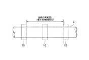
P:元管,
L:接続作業範囲,
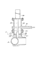
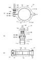
10:偏平矯正工具,
11(11A,11B):矯正片,
11a:板材,11b:リブ,
12:蝶番部,
13(13A,13B):密着部,
14:締結部,14A:締結軸,14B:嵌合部品,14C:締め付け部品,
15:被嵌合部,
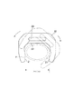
20:偏平確認ゲージ,21:ゲージ辺,22:当接辺,23:取っ手孔,
G:ゲージ間隔
Claims (3)
- 樹脂製の元管に活管状態で前記元管と同内径の分岐管を接続するために用いられる同径活管分岐継手の融着接続工法であって、
前記元管の内径と同径の内径を有する分岐管部と前記元管の外周を広範囲に覆って前記分岐管部を前記元管に装着するサドル部を備えた同径活管分岐継手を用い、前記同径活管分岐継手を前記元管に接続する接続作業範囲を前記元管の露出した外表面上に特定する接続作業範囲特定工程と、
前記接続作業範囲の両端に偏平矯正工具を装着し、前記接続作業範囲の両端に加えて前記接続作業範囲の間に偏平矯正工具を装着し、前記接続作業範囲における前記元管の外形の偏平状態を矯正する偏平矯正工程と、
前記偏平矯正工具を装着した後、前記接続作業範囲の間に装着した偏平矯正工具を取り外して、前記接続作業範囲における前記元管の偏平度が前記同径活管分岐継手を前記元管に精度良く融着できる許容範囲内であるか否かを、偏平確認ゲージを用いて確認する偏平確認工程と、
前記偏平確認工程で前記許容範囲内であると確認できた場合に、前記偏平矯正工具を装着した状態で前記同径活管分岐継手を前記接続作業範囲の外表面に融着接続する融着接続工程を有することを特徴とする同径活管分岐継手の融着接続工法。 - 前記偏平矯正工具は、前記元管の外周面に当接される内周面を有する一対の矯正片を有し、該矯正片の一端側が軸支され他端側には開閉自在な密着部が形成され、前記矯正片の外周には前記一端側から前記他端側に渡って平行に並んで配置された一対のリブを備え、該一対のリブ間に架け渡されるように前記密着部を締結する締結部が設けられていることを特徴とする請求項1に記載された同径活管分岐継手の融着接続工法。
- 前記偏平確認ゲージは、前記元管の基準外径に許容幅を加えたゲージ間隔を有する一対の平行なゲージ辺と、前記ゲージ辺内に前記元管の外周面と当接可能な当接辺とを有し、
前記偏平確認工程は、前記ゲージ辺間に前記元管を挿入して前記当接辺に前記元管の外周を当接させた状態で、前記元管の外周に沿って前記偏平確認ゲージを回転させることを特徴とする請求項1又は2に記載された同径活管分岐継手の融着接続工法。
Priority Applications (1)
| Application Number | Priority Date | Filing Date | Title |
|---|---|---|---|
| JP2010172788A JP5773593B2 (ja) | 2010-07-30 | 2010-07-30 | 同径活管分岐継手の融着接続工法 |
Applications Claiming Priority (1)
| Application Number | Priority Date | Filing Date | Title |
|---|---|---|---|
| JP2010172788A JP5773593B2 (ja) | 2010-07-30 | 2010-07-30 | 同径活管分岐継手の融着接続工法 |
Publications (2)
| Publication Number | Publication Date |
|---|---|
| JP2012031949A JP2012031949A (ja) | 2012-02-16 |
| JP5773593B2 true JP5773593B2 (ja) | 2015-09-02 |
Family
ID=45845598
Family Applications (1)
| Application Number | Title | Priority Date | Filing Date |
|---|---|---|---|
| JP2010172788A Active JP5773593B2 (ja) | 2010-07-30 | 2010-07-30 | 同径活管分岐継手の融着接続工法 |
Country Status (1)
| Country | Link |
|---|---|
| JP (1) | JP5773593B2 (ja) |
Family Cites Families (7)
| Publication number | Priority date | Publication date | Assignee | Title |
|---|---|---|---|---|
| JPS5851206U (ja) * | 1981-10-03 | 1983-04-07 | 井上 義康 | 線材製品用外径概測器 |
| JPH08178170A (ja) * | 1994-12-26 | 1996-07-12 | Seibu Gas Kk | ポリエチレン製ガス管用コールドリング |
| JP2001065772A (ja) * | 1999-08-30 | 2001-03-16 | Hitachi Metals Ltd | サドル継手の固定治具及び固定方法 |
| JP3644857B2 (ja) * | 1999-11-17 | 2005-05-11 | 大阪瓦斯株式会社 | 樹脂製配管部材の継手方法 |
| JP2002295776A (ja) * | 2001-03-29 | 2002-10-09 | Osaka Gas Co Ltd | 継手接続方法及び矯正治具 |
| JP4780663B2 (ja) * | 2006-06-20 | 2011-09-28 | 日立金属株式会社 | 合成樹脂管用活管分岐継手 |
| JP2010038231A (ja) * | 2008-08-04 | 2010-02-18 | Capty Co Ltd | 測定定規及び埋設樹脂管の扁平矯正方法 |
-
2010
- 2010-07-30 JP JP2010172788A patent/JP5773593B2/ja active Active
Also Published As
| Publication number | Publication date |
|---|---|
| JP2012031949A (ja) | 2012-02-16 |
Similar Documents
| Publication | Publication Date | Title |
|---|---|---|
| JP2009514689A (ja) | パイプ切断装置 | |
| AU2016229845B2 (en) | Method of joining pipes and apparatus for facilitating the same | |
| JP5773593B2 (ja) | 同径活管分岐継手の融着接続工法 | |
| JP4514047B2 (ja) | 樹脂製分岐管の撤去方法 | |
| JP6386320B2 (ja) | 樹脂製保温材付き曲管の製造方法 | |
| EP2617552A1 (en) | Improved integral pipe gripper | |
| JP5348779B2 (ja) | 配管分岐部材の撤去方法及び装置 | |
| JP2002295776A (ja) | 継手接続方法及び矯正治具 | |
| NL2023909B1 (nl) | Sanering van een buisleiding voorzien van een aftakking | |
| EP2594836A1 (en) | Purge tee assembly | |
| JP4497743B2 (ja) | 樹脂製分岐管の撤去方法 | |
| US10857739B2 (en) | System and method for spin welding fittings to maple sap lines | |
| JP5855148B2 (ja) | 分岐管継手 | |
| WO2017056204A1 (ja) | 樹脂製チューブ部材、配管及び、配管の製造方法 | |
| JP5577205B2 (ja) | 配管分岐部材の撤去方法 | |
| JP3183616U (ja) | 融着継手の接合用治具 | |
| JP3644857B2 (ja) | 樹脂製配管部材の継手方法 | |
| CN202685317U (zh) | 钢塑复合管加热夹具 | |
| JP5511153B2 (ja) | 管端面切削工具、管内面端面切削工具及び管の閉塞栓 | |
| JP6799459B2 (ja) | サドルクランプ装置 | |
| JP5508931B2 (ja) | 管口閉塞キャップを備えた管部材 | |
| JP2010038231A (ja) | 測定定規及び埋設樹脂管の扁平矯正方法 | |
| JP5916477B2 (ja) | 配管の曲線部の施工方法 | |
| JP2008169932A (ja) | 合成樹脂製コルゲート管部材の接続方法及び装置 | |
| JP4411454B2 (ja) | 防食処理管路の補修工法 |
Legal Events
| Date | Code | Title | Description |
|---|---|---|---|
| A621 | Written request for application examination |
Free format text: JAPANESE INTERMEDIATE CODE: A621 Effective date: 20130708 |
|
| A977 | Report on retrieval |
Free format text: JAPANESE INTERMEDIATE CODE: A971007 Effective date: 20140325 |
|
| A131 | Notification of reasons for refusal |
Free format text: JAPANESE INTERMEDIATE CODE: A131 Effective date: 20140422 |
|
| A521 | Request for written amendment filed |
Free format text: JAPANESE INTERMEDIATE CODE: A523 Effective date: 20140616 |
|
| A131 | Notification of reasons for refusal |
Free format text: JAPANESE INTERMEDIATE CODE: A131 Effective date: 20141125 |
|
| A521 | Request for written amendment filed |
Free format text: JAPANESE INTERMEDIATE CODE: A523 Effective date: 20150119 |
|
| TRDD | Decision of grant or rejection written | ||
| A01 | Written decision to grant a patent or to grant a registration (utility model) |
Free format text: JAPANESE INTERMEDIATE CODE: A01 Effective date: 20150616 |
|
| A61 | First payment of annual fees (during grant procedure) |
Free format text: JAPANESE INTERMEDIATE CODE: A61 Effective date: 20150630 |
|
| R150 | Certificate of patent or registration of utility model |
Ref document number: 5773593 Country of ref document: JP Free format text: JAPANESE INTERMEDIATE CODE: R150 |
|
| R250 | Receipt of annual fees |
Free format text: JAPANESE INTERMEDIATE CODE: R250 |
|
| R250 | Receipt of annual fees |
Free format text: JAPANESE INTERMEDIATE CODE: R250 |
|
| R250 | Receipt of annual fees |
Free format text: JAPANESE INTERMEDIATE CODE: R250 |
|
| R250 | Receipt of annual fees |
Free format text: JAPANESE INTERMEDIATE CODE: R250 |
|
| R250 | Receipt of annual fees |
Free format text: JAPANESE INTERMEDIATE CODE: R250 |
|
| R250 | Receipt of annual fees |
Free format text: JAPANESE INTERMEDIATE CODE: R250 |
|
| R250 | Receipt of annual fees |
Free format text: JAPANESE INTERMEDIATE CODE: R250 |