JP5456678B2 - Customized patient-specific orthopedic surgical instruments - Google Patents
Customized patient-specific orthopedic surgical instruments Download PDFInfo
- Publication number
- JP5456678B2 JP5456678B2 JP2010527242A JP2010527242A JP5456678B2 JP 5456678 B2 JP5456678 B2 JP 5456678B2 JP 2010527242 A JP2010527242 A JP 2010527242A JP 2010527242 A JP2010527242 A JP 2010527242A JP 5456678 B2 JP5456678 B2 JP 5456678B2
- Authority
- JP
- Japan
- Prior art keywords
- patient
- bone
- cutting
- guide
- cutting block
- Prior art date
- Legal status (The legal status is an assumption and is not a legal conclusion. Google has not performed a legal analysis and makes no representation as to the accuracy of the status listed.)
- Active
Links
- 230000000399 orthopedic effect Effects 0.000 title claims description 630
- 238000005520 cutting process Methods 0.000 claims description 1944
- 210000000988 bone and bone Anatomy 0.000 claims description 1365
- 210000000689 upper leg Anatomy 0.000 claims description 441
- 239000000463 material Substances 0.000 claims description 51
- 239000007769 metal material Substances 0.000 claims description 12
- 238000000034 method Methods 0.000 description 288
- 210000002303 tibia Anatomy 0.000 description 272
- 210000000845 cartilage Anatomy 0.000 description 72
- 210000002414 leg Anatomy 0.000 description 56
- 238000005553 drilling Methods 0.000 description 55
- 238000001356 surgical procedure Methods 0.000 description 49
- 238000003780 insertion Methods 0.000 description 48
- 230000037431 insertion Effects 0.000 description 48
- 238000003801 milling Methods 0.000 description 45
- 238000013461 design Methods 0.000 description 42
- 210000003041 ligament Anatomy 0.000 description 37
- 210000003423 ankle Anatomy 0.000 description 32
- 238000004891 communication Methods 0.000 description 24
- 238000013440 design planning Methods 0.000 description 20
- 210000003127 knee Anatomy 0.000 description 19
- 230000008569 process Effects 0.000 description 18
- 238000002271 resection Methods 0.000 description 16
- 230000008878 coupling Effects 0.000 description 14
- 238000010168 coupling process Methods 0.000 description 14
- 238000005859 coupling reaction Methods 0.000 description 14
- 239000003550 marker Substances 0.000 description 13
- 238000004519 manufacturing process Methods 0.000 description 12
- 239000004033 plastic Substances 0.000 description 12
- 229920003023 plastic Polymers 0.000 description 12
- 238000003860 storage Methods 0.000 description 12
- 230000007704 transition Effects 0.000 description 12
- 125000001475 halogen functional group Chemical group 0.000 description 11
- 210000003813 thumb Anatomy 0.000 description 11
- 239000011347 resin Substances 0.000 description 9
- 229920005989 resin Polymers 0.000 description 9
- 208000008558 Osteophyte Diseases 0.000 description 8
- 238000009412 basement excavation Methods 0.000 description 8
- 239000007943 implant Substances 0.000 description 8
- 230000007935 neutral effect Effects 0.000 description 7
- 239000002131 composite material Substances 0.000 description 6
- 210000001519 tissue Anatomy 0.000 description 6
- 238000004458 analytical method Methods 0.000 description 5
- 210000003484 anatomy Anatomy 0.000 description 5
- 201000010934 exostosis Diseases 0.000 description 5
- 210000000629 knee joint Anatomy 0.000 description 5
- RYGMFSIKBFXOCR-UHFFFAOYSA-N Copper Chemical compound [Cu] RYGMFSIKBFXOCR-UHFFFAOYSA-N 0.000 description 4
- 239000004642 Polyimide Substances 0.000 description 4
- 229920004738 ULTEM® Polymers 0.000 description 4
- 238000002591 computed tomography Methods 0.000 description 4
- 229910052802 copper Inorganic materials 0.000 description 4
- 239000010949 copper Substances 0.000 description 4
- 230000007812 deficiency Effects 0.000 description 4
- 239000000835 fiber Substances 0.000 description 4
- 229920001721 polyimide Polymers 0.000 description 4
- 230000004044 response Effects 0.000 description 4
- 229920005992 thermoplastic resin Polymers 0.000 description 4
- 238000002679 ablation Methods 0.000 description 3
- 230000008901 benefit Effects 0.000 description 3
- 230000007423 decrease Effects 0.000 description 3
- 210000003811 finger Anatomy 0.000 description 3
- 230000036541 health Effects 0.000 description 3
- 238000012986 modification Methods 0.000 description 3
- 230000004048 modification Effects 0.000 description 3
- 238000012545 processing Methods 0.000 description 3
- 230000006870 function Effects 0.000 description 2
- 230000005484 gravity Effects 0.000 description 2
- 238000003384 imaging method Methods 0.000 description 2
- 239000002184 metal Substances 0.000 description 2
- 229910052751 metal Inorganic materials 0.000 description 2
- 210000000426 patellar ligament Anatomy 0.000 description 2
- 229920000642 polymer Polymers 0.000 description 2
- 210000002967 posterior cruciate ligament Anatomy 0.000 description 2
- 238000012552 review Methods 0.000 description 2
- 210000004872 soft tissue Anatomy 0.000 description 2
- 239000013589 supplement Substances 0.000 description 2
- 238000011883 total knee arthroplasty Methods 0.000 description 2
- 241001227561 Valgus Species 0.000 description 1
- 241000469816 Varus Species 0.000 description 1
- 230000009471 action Effects 0.000 description 1
- 239000000853 adhesive Substances 0.000 description 1
- 230000001070 adhesive effect Effects 0.000 description 1
- 238000011882 arthroplasty Methods 0.000 description 1
- 238000005452 bending Methods 0.000 description 1
- 239000002639 bone cement Substances 0.000 description 1
- 230000006835 compression Effects 0.000 description 1
- 238000007906 compression Methods 0.000 description 1
- 238000005094 computer simulation Methods 0.000 description 1
- 238000011960 computer-aided design Methods 0.000 description 1
- 239000002872 contrast media Substances 0.000 description 1
- 238000002059 diagnostic imaging Methods 0.000 description 1
- 238000010586 diagram Methods 0.000 description 1
- 239000003814 drug Substances 0.000 description 1
- 229940079593 drug Drugs 0.000 description 1
- 238000003708 edge detection Methods 0.000 description 1
- 230000000694 effects Effects 0.000 description 1
- 238000005516 engineering process Methods 0.000 description 1
- 239000004744 fabric Substances 0.000 description 1
- 230000003116 impacting effect Effects 0.000 description 1
- 238000002513 implantation Methods 0.000 description 1
- 230000007246 mechanism Effects 0.000 description 1
- 210000004417 patella Anatomy 0.000 description 1
- 238000013439 planning Methods 0.000 description 1
- 239000011505 plaster Substances 0.000 description 1
- 238000007493 shaping process Methods 0.000 description 1
- 238000004088 simulation Methods 0.000 description 1
- 238000005549 size reduction Methods 0.000 description 1
- 230000000087 stabilizing effect Effects 0.000 description 1
- 239000000758 substrate Substances 0.000 description 1
- 238000003325 tomography Methods 0.000 description 1
- 239000012780 transparent material Substances 0.000 description 1
- 238000010200 validation analysis Methods 0.000 description 1
- 230000000007 visual effect Effects 0.000 description 1
Images


Classifications
-
- A—HUMAN NECESSITIES
- A61—MEDICAL OR VETERINARY SCIENCE; HYGIENE
- A61B—DIAGNOSIS; SURGERY; IDENTIFICATION
- A61B17/00—Surgical instruments, devices or methods, e.g. tourniquets
- A61B17/14—Surgical saws ; Accessories therefor
- A61B17/15—Guides therefor
- A61B17/154—Guides therefor for preparing bone for knee prosthesis
- A61B17/155—Cutting femur
-
- A—HUMAN NECESSITIES
- A61—MEDICAL OR VETERINARY SCIENCE; HYGIENE
- A61B—DIAGNOSIS; SURGERY; IDENTIFICATION
- A61B17/00—Surgical instruments, devices or methods, e.g. tourniquets
- A61B17/14—Surgical saws ; Accessories therefor
- A61B17/15—Guides therefor
- A61B17/154—Guides therefor for preparing bone for knee prosthesis
- A61B17/157—Cutting tibia
-
- A—HUMAN NECESSITIES
- A61—MEDICAL OR VETERINARY SCIENCE; HYGIENE
- A61B—DIAGNOSIS; SURGERY; IDENTIFICATION
- A61B17/00—Surgical instruments, devices or methods, e.g. tourniquets
- A61B17/16—Bone cutting, breaking or removal means other than saws, e.g. Osteoclasts; Drills or chisels for bones; Trepans
- A61B17/17—Guides or aligning means for drills, mills, pins or wires
- A61B17/1739—Guides or aligning means for drills, mills, pins or wires specially adapted for particular parts of the body
- A61B17/1764—Guides or aligning means for drills, mills, pins or wires specially adapted for particular parts of the body for the knee
-
- A—HUMAN NECESSITIES
- A61—MEDICAL OR VETERINARY SCIENCE; HYGIENE
- A61B—DIAGNOSIS; SURGERY; IDENTIFICATION
- A61B17/00—Surgical instruments, devices or methods, e.g. tourniquets
- A61B2017/00526—Methods of manufacturing
-
- A—HUMAN NECESSITIES
- A61—MEDICAL OR VETERINARY SCIENCE; HYGIENE
- A61B—DIAGNOSIS; SURGERY; IDENTIFICATION
- A61B17/00—Surgical instruments, devices or methods, e.g. tourniquets
- A61B17/56—Surgical instruments or methods for treatment of bones or joints; Devices specially adapted therefor
- A61B2017/568—Surgical instruments or methods for treatment of bones or joints; Devices specially adapted therefor produced with shape and dimensions specific for an individual patient
-
- A—HUMAN NECESSITIES
- A61—MEDICAL OR VETERINARY SCIENCE; HYGIENE
- A61B—DIAGNOSIS; SURGERY; IDENTIFICATION
- A61B34/00—Computer-aided surgery; Manipulators or robots specially adapted for use in surgery
- A61B34/10—Computer-aided planning, simulation or modelling of surgical operations
- A61B2034/108—Computer aided selection or customisation of medical implants or cutting guides
-
- Y—GENERAL TAGGING OF NEW TECHNOLOGICAL DEVELOPMENTS; GENERAL TAGGING OF CROSS-SECTIONAL TECHNOLOGIES SPANNING OVER SEVERAL SECTIONS OF THE IPC; TECHNICAL SUBJECTS COVERED BY FORMER USPC CROSS-REFERENCE ART COLLECTIONS [XRACs] AND DIGESTS
- Y10—TECHNICAL SUBJECTS COVERED BY FORMER USPC
- Y10T—TECHNICAL SUBJECTS COVERED BY FORMER US CLASSIFICATION
- Y10T409/00—Gear cutting, milling, or planing
- Y10T409/30—Milling
- Y10T409/30084—Milling with regulation of operation by templet, card, or other replaceable information supply
Landscapes
- Health & Medical Sciences (AREA)
- Surgery (AREA)
- Life Sciences & Earth Sciences (AREA)
- Biomedical Technology (AREA)
- Public Health (AREA)
- Oral & Maxillofacial Surgery (AREA)
- Nuclear Medicine, Radiotherapy & Molecular Imaging (AREA)
- Veterinary Medicine (AREA)
- Dentistry (AREA)
- Engineering & Computer Science (AREA)
- Orthopedic Medicine & Surgery (AREA)
- Heart & Thoracic Surgery (AREA)
- Medical Informatics (AREA)
- Molecular Biology (AREA)
- Animal Behavior & Ethology (AREA)
- General Health & Medical Sciences (AREA)
- Physical Education & Sports Medicine (AREA)
- Transplantation (AREA)
- Surgical Instruments (AREA)
- Prostheses (AREA)
Description
本願は、ダン・オーガー(Dan Auger)らによって2007年9月30日に出願された、名称「カスタマイズされた専売特許器具を製作するための方法及び装置(Method and Apparatus for Fabricating Customized Patent Instrumentation)」の米国特許仮出願第60/976,447号、ルーク・アラム(Luke Aram)らによって2007年9月30日に出願された、名称「調整可能なカスタマイズされた患者別の整形外科用手術器具(Adjustable Customized Patient-Specific Orthopaedic Surgical Instrumentation)」の米国特許仮出願第60/976,448号、ジェフ・ローゼ(Jeff Roose)らによって2007年9月30日に出願された、名称「整形外科手術で使用するためのカスタマイズされた患者別の器具(Customized Patient-Specific Instrumentation For Use In Orthopaedic Surgical Procedures)」の米国特許仮出願第60/976,451号、ルーク・アラム(Luke Aram)らによって2007年9月30日に出願された、名称「整形外科用手術器具を患者別に位置決めするための方法及び装置(Method and Apparatus for Patient-Specific Positioning of Orthopaedic Surgical Instrumentation)」の米国特許仮出願第60/976,444号、及びルーク・アラム(Luke Aram)らによって2007年9月30日に出願された、名称「カスタマイズされた患者別の整形外科用手術器具を整合させるための方法及び装置(Method and Apparatus for Aligning Customized Patient-Specific Orthopaedic Surgical Instruments)」の米国特許仮出願第60/976,446号の米国特許法第119条(e)下の優先権を主張し、これらのそれぞれは、本願と同一の譲受人に譲渡され、これらのそれぞれは、参照することによって本明細書に組み込まれる。 This application was filed on September 30, 2007, by Dan Auger et al., With the name “Method and Apparatus for Fabricating Customized Patent Instrumentation”. US Patent Provisional Application No. 60 / 976,447, filed September 30, 2007 by Luke Aram et al., Entitled “Adjustable customized patient-specific orthopedic surgical instrument ( US Patent Provisional Application No. 60 / 976,448, “Adjustable Customized Patient-Specific Orthopaedic Surgical Instrumentation”, filed September 30, 2007 by Jeff Roose et al. US Patent for “Customized Patient-Specific Instrumentation For Use In Orthopaedic Surgical Procedures” Provisional Application No. 60 / 976,451, filed September 30, 2007 by Luke Aram et al., Entitled “Method and Apparatus for Positioning Orthopedic Surgical Instruments by Patient” Apparatus for Patient-Specific Positioning of Orthopaedic Surgical Instrumentation ”, US Provisional Patent Application No. 60 / 976,444, and Luke Aram et al. US Patent Provisional Application No. 60 / 976,446 to Method and Apparatus for Aligning Customized Patient-Specific Orthopaedic Surgical Instruments Claim priority under section (e), each of which is assigned to the same assignee as the present application, each of which shall be referred to Thus, it is incorporated herein.
〔関連する米国特許出願の相互参照〕
ルーク・アラム(Luke Aram)らによって出願された、名称「骨の再切断を実施するためのカスタマイズされた患者別の器具及び方法(Customized Patient-Specific Instrumentation And Method For Performing A Bone Re-cut)」の同時係属の米国特許出願第XX/XXX,XXX号(代理人整理番号265280−207006、DEP−6046USNP)、ルーク・アラム(Luke Aram)らによって出願された、名称「整形外科手術で使用するためのカスタマイズされた患者別の器具(Customized Patient-Specific Instrumentation for Use In Orthopaedic Surgical Procedures)」の同時係属の米国特許出願第XX/XXX,XXX号(代理人整理番号265280−207007、DEP−6047USNP)、トラビス・ベニト(Travis Bennett)によって出願された、名称「整形外科的骨のこぎり及びその使用方法(Orthopaedic Bone Saw And Method of Use Thereof)」の同時係属の米国特許出願第XX/XXX,XXX号(代理人整理番号265280−207008、DEP−6046USNP1)、エリック・ゼイジャック(Eric Zajac)によって出願された、名称「カスタマイズされた患者別の骨切断ブロック(Customized Patient-Specific Bone Cutting Blocks)」の同時係属の米国特許出願第XX/XXX,XXX号(代理人整理番号265280−207009、DEP−6047USNP1)、クリストファー・エイカー(Christopher Aker)らによって出願された、名称「カスタマイズされた患者別の多切断ブロック(Customized Patient-Specific Multi-Cutting Blocks)」の同時係属の米国特許出願第XX/XXX,XXX号(代理人整理番号265280−207010、DEP−6048USNP)、ルーク・アラム(Luke Aram)らによって出願された、名称「カスタマイズされた患者別の骨切断器具(Customized Patient-Specific Bone Cutting Instrumentation)」の同時係属の米国特許出願第XX/XXX,XXX号(代理人整理番号265280−207011、DEP−6048USNP1)、クリストファー・エイカー(Christopher Aker)らによって出願された、名称「大腿骨/脛骨用のカスタマイズされた患者別の整形外科用手術器具(Femoral/Tibial Customized Patient Specific Orthopaedic Surgical Instrumentation)」の同時係属の米国特許出願第XX/XXX,XXX号(代理人整理番号265280−207012、DEP−6047USNP2)、クリストファー・エイカー(Christopher Aker)らによって出願された、名称「調整可能なカスタマイズされた患者別の整形外科用手術器具(Adjustable Customized Patient-Specific Orthopaedic Surgical Instrumentation)」の同時係属の米国特許出願第XX/XXX,XXX号(代理人整理番号265280−207013、DEP−6048USNP2)、ジェフ・ローゼ(Jeff Roose)らによって出願された、名称「カスタマイズされた患者別の手術器具を製作するためのシステム及び方法(System and Method For Fabricating A Customized Patient-Specific Surgical Instrument)」の同時係属の米国特許出願第XX/XXX,XXX号(代理人整理番号265280−207014、DEP−6050USNP1)、ルーク・アラム(Luke Aram)らによって出願された、名称「外部参照を有するカスタマイズされた患者別の骨切断ブロック(Customized Patient-Specific Bone Cutting Block With External Reference)」の同時係属の米国特許出願第XX/XXX,XXX号(代理人整理番号265280−207015、DEP−6050USNP)、ブライアン・ローズ(Bryan Rose)によって出願された、名称「カスタマイズされた患者別の整形外科用器具を製作するための装置及び方法(Apparatus and Method for Fabricating A Customized Patient-Specific Orthopaedic Instrument)」の同時係属の米国特許出願第XX/XXX,XXX号(代理人整理番号265280−207016、DEP−6049USNP1)、及びジェフ・ローゼ(Jeff Roose)によって出願された、名称「整形外科手術を実施するための患者用にカスタマイズ可能な装置及びシステム(Patient-Customizable Device And System For Performing An Orthopaedic Surgical Procedures)」の同時係属の米国特許出願第XX/XXX,XXX号(代理人整理番号265280−207018、DEP−6049USNP)が相互参照され、これらのそれぞれは、本願と同一の譲受人に譲渡され、これらのそれぞれは、本願と同時に出願され、これらのそれぞれは、参照することによって本明細書に組み込まれる。
[Cross-reference of related US patent applications]
Named “Customized Patient-Specific Instrumentation And Method For Performing A Bone Re-cut” filed by Luke Aram et al. US Patent Application No. XX / XXX, XXX (Attorney Docket No. 265280-207006, DEP-6046USNP), filed by Luke Aram et al., For use in orthopedic surgery US Patent Application No. XX / XXX, XXX (Attorney Docket No. 265280-207007, DEP-6047USNP), co-pending “Customized Patient-Specific Instrumentation for Use In Orthopaedic Surgical Procedures”, The name “Orthopedic Bone Saw” filed by Travis Bennett US Patent Application No. XX / XXX, XXX (Attorney Docket No. 265280-207008, DEP-6046USNP1), “Orthopaedic Bone Saw And Method of Use Thereof”, Eric Zajac Co-pending U.S. Patent Application No. XX / XXX, XXX (Attorney Docket No. 265280-207090, DEP) filed by the name "Customized Patient-Specific Bone Cutting Blocks" -6047 USNP1), co-pending US patent application XX / XXX filed by Christopher Aker et al. Under the name “Customized Patient-Specific Multi-Cutting Blocks” , XXX (Attorney Docket No. 265280-207010 , DEP-6048 USNP), co-pending US Patent Application No. XX /, filed by Luke Aram et al. Under the name “Customized Patient-Specific Bone Cutting Instrumentation”. Customized patient-specific orthopedic surgical instrument for femur / tibia, filed by Christopher Aker et al., XXX, XXX (Attorney Docket No. 265280-207011, DEP-6048USNP1) (Femoral / Tibial Customized Patient Specific Orthopaedic Surgical Instrumentation), filed by co-pending US Patent Application No. XX / XXX, XXX (Attorney Docket No. 265280-207012, DEP-6047USNP2), Christopher Aker et al. The name “adjustable” US Patent Application No. XX / XXX, XXX (Attorney Docket No. 265280-207013, DEP-6048USNP2) of “Adjustable Customized Patient-Specific Orthopaedic Surgical Instrumentation”, Co-pending the name “System and Method For Fabricating A Customized Patient-Specific Surgical Instrument” filed by Jeff Roose et al. US Patent Application No. XX / XXX, XXX (Attorney Docket No. 265280-207014, DEP-6050USNP1), Luke Aram et al., Entitled “Customized Patient-Specific Bone with External Reference” Cutting Block (Customized Patient-Specific Bone Cutting Block W ith External Reference), co-pending U.S. Patent Application No. XX / XXX, XXX (Attorney Docket No. 265280-207015, DEP-6050USNP), filed by Bryan Rose U.S. Patent Application No. XX / XXX, XXX (Attorney Docket No. 265280) for "Apparatus and Method for Fabricating A Customized Patient-Specific Orthopaedic Instrument" -207016, DEP-6049USNP1), and Jeff Roose, the name “Patient-Customizable Device And System For Performing An Orthopaedic Surgical Procedures) ”co-pending US patent application No. X / XXX, XXX (Attorney Docket No. 265280-207018, DEP-6049USNP) are cross-referenced, each of which is assigned to the same assignee as the present application, each of which is filed concurrently with the present application, Each of which is incorporated herein by reference.
〔発明の技術分野〕
本開示は、概して、カスタマイズされた患者別の整形外科用手術器具(customized patient-specific orthopaedic surgical instruments)、並びにかかる器具を製作し位置決めするための方法、装置及びシステムに関する。
[Technical Field of the Invention]
The present disclosure generally relates to customized patient-specific orthopaedic surgical instruments and methods, apparatus and systems for making and positioning such instruments.
〔背景技術〕
関節形成術は、疾患及び/又は損傷した天然関節を人工関節で置き換える周知の外科手術である。典型的な膝プロテーゼは、脛骨トレイ、大腿骨コンポーネント、ポリマー挿入物、又は脛骨トレイと大腿骨コンポーネントとの間に位置決めされる軸受部、場合によっては、ポリマー膝蓋ボタンを含む。天然関節を人工膝関節で置き換えることを容易にするために、整形外科医は、例えば切断ブロック、掘削ガイド、ミリングガイド、及び他の手術器具等の様々な整形外科用手術器具を使用する。通常、整形外科用手術器具は患者に関して一般的であるため、類似する整形外科手術中に、同一の整形外科用手術器具が何人かの異なる患者に使用される場合がある。
[Background Technology]
Arthroplasty is a well-known surgical procedure that replaces a diseased and / or damaged natural joint with an artificial joint. A typical knee prosthesis includes a tibial tray, a femoral component, a polymer insert, or a bearing positioned between the tibial tray and the femoral component, and in some cases a polymer patella button. In order to facilitate the replacement of natural joints with knee prostheses, orthopedic surgeons use a variety of orthopedic surgical instruments such as cutting blocks, drilling guides, milling guides, and other surgical instruments. Since orthopedic surgical instruments are typically common for patients, the same orthopedic surgical instrument may be used for several different patients during a similar orthopedic surgery.
〔概要〕
一態様によると、患者の骨に整形外科手術を実施する方法が開示される。本方法は、カスタマイズされた患者別の切断ブロックを、患者の骨に接触させて位置決めする工程を含むことができる。いくつかの実施形態において、本方法は、カスタマイズされた患者別の切断ブロックを、患者の大腿骨に接触させて位置決めする工程を含むことができる。いくつかの実施形態において、本方法は、カスタマイズされた患者別の切断ブロックを、患者の脛骨に接触させて位置決めする工程を含むことができる。本方法は、一対のガイドピンを、カスタマイズされた患者別の切断ブロック内に画定された一対のガイドピン穴に挿入する工程を含むことができる。本方法は、カスタマイズされた患者別の切断ブロックを用いて、患者の骨に第1の切り目を入れる工程も含むことができる。いくつかの実施形態において、本方法は、カスタマイズされた患者別の切断ブロックを用いて、患者の大腿骨に第1の切り目を入れる工程を含んでもよい。他の実施形態においては、本方法は、カスタマイズされた患者別の切断ブロックを用いて、患者の脛骨に第1の切り目を入れる工程を含んでもよい。本方法は、ガイドピンを患者の骨から取り外すことなく、カスタマイズされた患者別の切断ブロックを患者の骨から取り外す工程も含むことができる。
〔Overview〕
According to one aspect, a method for performing orthopedic surgery on a patient's bone is disclosed. The method may include positioning a customized patient-specific cutting block in contact with the patient's bone. In some embodiments, the method can include positioning a customized patient-specific cutting block in contact with the patient's femur. In some embodiments, the method can include positioning a customized patient-specific cutting block in contact with the patient's tibia. The method can include inserting a pair of guide pins into a pair of guide pin holes defined in a customized patient-specific cutting block. The method can also include the step of making a first cut in the patient's bone using a customized patient-specific cutting block. In some embodiments, the method may include the step of making a first cut in the patient's femur using a customized patient-specific cutting block. In other embodiments, the method may include making a first cut in the patient's tibia using a customized patient-specific cutting block. The method may also include removing the customized patient-specific cutting block from the patient's bone without removing the guide pin from the patient's bone.
本方法は、一対のガイドピンを、患者共通の再切断ブロック内に画定された一対のガイドピン穴に挿入する工程と、この患者共通の再切断ブロックを用いて、患者の骨に第2の切り目を入れる工程と、を含むことができる。いくつかの実施形態において、本方法は、患者共通の再切断ブロックを用いて、患者の大腿骨に第2の切り目を入れる工程を含んでもよい。本方法は、患者の大腿骨に、第1の切り目に対してほぼ平行である、第2の切り目を入れる工程も含むことができる。加えて、いくつかの実施形態において、本方法は、大腿骨に、第1の切り目に対して傾斜位置で配向される、第2の切り目を入れる工程を含んでもよい。 The method includes inserting a pair of guide pins into a pair of guide pin holes defined in a patient common recut block, and using the patient common recut block to a second bone in the patient's bone. Incision. In some embodiments, the method may include the step of making a second incision in the patient's femur using a patient common recut block. The method can also include making a second incision in the patient's femur that is substantially parallel to the first incision. In addition, in some embodiments, the method may include making a second incision in the femur that is oriented at an inclined position relative to the first incision.
いくつかの実施形態において、本方法は、患者共通の再切断ブロックを用いて、患者の脛骨に第2の切り目を入れる工程を含んでもよい。本方法は、患者の脛骨に、第1の切り目に対してほぼ平行である、第2の切り目を入れる工程を含むことができる。加えて、いくつかの実施形態において、本方法は、脛骨に、第1の切り目に対して傾斜位置で配向される、第2の切り目を入れる工程を含んでもよい。 In some embodiments, the method may include making a second incision in the patient's tibia using a patient common recut block. The method can include making a second cut in the patient's tibia that is substantially parallel to the first cut. In addition, in some embodiments, the method may include making a second incision in the tibia that is oriented at an inclined position relative to the first incision.
いくつかの実施形態において、本方法は、患者共通の再切断ブロックの切断ガイドが第1の切り目に対してほぼ平行となるように、一対のガイドピンを、患者共通の再切断ブロック内に画定された一対のガイドピン穴に挿入する工程を含んでもよい。本方法は、第2の切り目が第1の切り目に対してほぼ平行となるように、患者共通の再切断ブロックを用いて、患者の骨に第2の切り目を入れる工程を含んでもよい。加えて、いくつかの実施形態において、患者共通の再切断ブロックの切断ガイドは、第1の切り目に対して傾斜位置で配向されてもよい。本方法は、第2の切り目が第1の切り目に対して傾斜位置で配向されるように、患者共通の再切断ブロックを用いて、患者の骨に第2の切り目を入れる工程を含んでもよい。 In some embodiments, the method defines a pair of guide pins within the patient common recut block such that the cutting guide of the patient common recut block is substantially parallel to the first cut. A step of inserting the pair of guide pin holes may be included. The method may include making a second cut in the patient's bone using a patient common recut block so that the second cut is substantially parallel to the first cut. In addition, in some embodiments, the patient common recut block cutting guide may be oriented in an inclined position relative to the first cut. The method may include the step of making a second cut in the patient's bone using a patient common recut block such that the second cut is oriented at an inclined position relative to the first cut. .
いくつかの実施形態において、本方法は、カスタマイズされた患者別の切断ブロックを用いて、患者の骨に第1の切り目を入れる工程の後に、患者の骨から除去される追加の骨の量を決定する工程を含むことができる。本方法は、患者の骨から除去される追加の骨の量に対応する一対のガイドピン穴を、患者共通の再切断ブロック内に画定された複数対のガイドピン穴から選択する工程を含むことができる。本方法は、一対のガイドピンを、患者共通の再切断ブロック内に画定された、患者の骨から除去される追加の骨の量に対応する、選択された一対のガイドピン穴に挿入する工程を含み得る。 In some embodiments, the method uses a customized patient-specific cutting block to measure the amount of additional bone removed from the patient's bone after the first cut is made in the patient's bone. A step of determining may be included. The method includes selecting a pair of guide pin holes corresponding to the amount of additional bone removed from the patient's bone from a plurality of pairs of guide pin holes defined in a patient common recut block. Can do. The method includes inserting a pair of guide pins into a selected pair of guide pin holes, which are defined in the patient's common recut block, corresponding to the amount of additional bone removed from the patient's bone. Can be included.
別の態様によると、整形外科用器具アセンブリは、カスタマイズされた患者別の切断ブロックと、患者共通の再切断ブロックと、を含むことができる。いくつかの実施形態において、カスタマイズされた患者別の切断ブロックは、患者別の大腿骨切断ブロックであってもよく、患者共通の再切断ブロックは、患者共通の大腿骨再切断ブロックであってもよい。他の実施形態においては、カスタマイズされた患者別の切断ブロックは、患者別の脛骨切断ブロックであってもよく、患者共通の再切断ブロックは、患者共通の大腿骨再切断ブロックであってもよい。 According to another aspect, the orthopedic instrument assembly can include a customized patient-specific cutting block and a common patient recutting block. In some embodiments, the customized patient-specific cutting block may be a patient-specific femoral cutting block, and the patient common recutting block may be a patient common femoral recutting block Good. In other embodiments, the customized patient-specific cutting block may be a patient-specific tibial cutting block, and the patient-common recut block may be a patient-common femoral recut block .
カスタマイズされた患者別の切断ブロックは、切断ガイド、及び一対のガイドピン穴、を含んでもよい。患者共通の再切断ブロックは、切断ガイド、及び複数対のガイドピン穴、を含んでもよい。患者共通の再切断ブロックのガイドピン穴のそれぞれの対は、カスタマイズされた患者別の切断ブロックの一対のガイドピン穴と直径及び間隔が対応してもよい。 The customized patient-specific cutting block may include a cutting guide and a pair of guide pin holes. The patient common recut block may include a cutting guide and multiple pairs of guide pin holes. Each pair of guide pin holes in a patient common recut block may correspond in diameter and spacing to a pair of guide pin holes in a customized patient specific cut block.
いくつかの実施形態において、患者共通の再切断ブロックの一対のガイドピン穴が、カスタマイズされた患者別の切断ブロックの一対のガイドピン穴と整合される際に、患者共通の再切断ブロックの切断ガイドは、カスタマイズされた患者別の切断ブロックの切断ガイドに対してほぼ平行であってもよい。いくつかの実施形態において、患者共通の再切断ブロックの一対のガイドピン穴が、カスタマイズされた患者別の切断ブロックの一対のガイドピン穴と整合される際に、患者共通の再切断ブロックの切断ガイドは、カスタマイズされた患者別の切断ブロックの切断ガイドに対して傾斜位置で配向されてもよい。 In some embodiments, the patient common recut block cutting when the pair of guide pin holes of the patient common recut block is aligned with the pair of guide pin holes of the customized patient specific cut block. The guide may be substantially parallel to the cutting guide of the customized patient-specific cutting block. In some embodiments, the patient common recut block cutting when the pair of guide pin holes of the patient common recut block is aligned with the pair of guide pin holes of the customized patient specific cut block. The guide may be oriented in an inclined position relative to the cutting guide of the customized patient-specific cutting block.
別の態様において、患者の大腿骨に整形外科手術を実施する方法が開示される。本方法は、カスタマイズされた患者別の切断ブロックを、患者の大腿骨に接触させて位置決め又は配置する工程と、一対のガイドピンを、カスタマイズされた患者別の切断ブロック内に画定された一対のガイドピン穴に挿入する工程と、を含むことができる。また、本方法は、カスタマイズされた患者別の切断ブロックを用いて、患者の大腿骨に第1の切り目を入れる工程も含んでもよい。本方法は、ガイドピンを患者の大腿骨から取り外すことなく、カスタマイズされた患者別の切断ブロックを取り外す工程を含むことができる。また、本方法は、大腿骨に第1の切り目を入れる工程の後に、患者の大腿骨から除去される追加の骨の量を決定する工程と、患者の大腿骨から除去される追加の骨の量に対応する、患者共通の再切断ブロック内に画定された一対のガイドピン穴を、複数対のガイドピン穴から選択する工程と、を含むことができる。 In another aspect, a method for performing orthopedic surgery on a patient's femur is disclosed. The method includes the steps of positioning or placing a customized patient-specific cutting block in contact with the patient's femur and a pair of guide pins defined in the customized patient-specific cutting block. Inserting into the guide pin hole. The method may also include the step of making a first cut in the patient's femur using a customized patient-specific cutting block. The method can include removing the customized patient-specific cutting block without removing the guide pin from the patient's femur. The method also includes determining the amount of additional bone removed from the patient's femur after the step of making a first incision in the femur, and the additional bone removed from the patient's femur. Selecting from a plurality of pairs of guide pin holes a pair of guide pin holes defined in the patient common recut block corresponding to the quantity.
本方法は、一対のガイドピンを、患者共通の再切断ブロック内に画定された、患者の大腿骨から除去される追加の骨の量に対応する、選択された一対のガイドピン穴に挿入する工程を更に含むことができる。本方法は、患者共通の再切断ブロックを用いて、患者の大腿骨に第2の切り目を入れる工程を含むことができる。いくつかの実施形態において、本方法は、患者共通の再切断ブロックの切断ガイドが第1の切り目に対してほぼ平行となるように、一対のガイドピンを、選択された一対のガイドピン穴に挿入する工程を含んでもよい。本方法は、第2の切り目が第1の切り目に対してほぼ平行となるように、患者共通の再切断ブロックを用いて、患者の大腿骨に第2の切り目を入れる工程を含むことができる。加えて、いくつかの実施形態において、本方法は、患者共通の再切断ブロックの切断ガイドが第1の切り目に対して傾斜位置で配向されるように、一対のガイドピンを、選択された一対のガイドピン穴に挿入する工程を含んでもよい。本方法は、第2の切り目が第1の切り目に対して傾斜位置で配向されるように、患者共通の再切断ブロックを用いて、患者の大腿骨に第2の切り目を入れる工程を含むことができる。 The method inserts a pair of guide pins into a selected pair of guide pin holes corresponding to the amount of additional bone defined in the patient's common recut block that is removed from the patient's femur. A process can further be included. The method can include the step of making a second incision in the patient's femur using a patient common recut block. In some embodiments, the method includes placing a pair of guide pins into a selected pair of guide pin holes such that the patient common recut block cutting guide is substantially parallel to the first cut. A step of inserting may be included. The method can include the step of making a second cut in the patient's femur using a patient common recut block such that the second cut is substantially parallel to the first cut. . In addition, in some embodiments, the method includes selecting a pair of guide pins so that the patient-common recut block cutting guide is oriented at an inclined position relative to the first cut. The step of inserting into the guide pin hole may be included. The method includes the step of making a second cut in the patient's femur using a patient common recut block such that the second cut is oriented at an inclined position relative to the first cut. Can do.
一態様によると、患者の骨を切断するための整形外科的骨のこぎりが開示される。整形外科的骨のこぎりは、骨のこ刃を受容するよう構成されたチャックと、骨のこぎりを患者の骨に対して所定の位置で整合させるために、1つ以上の手術用ガイドピンを受容するよう構成されたガイドと、を含むことができる。いくつかの実施形態において、ガイドは、1つ以上の手術用ガイドピンを受容するために、1つ以上の開口部を有する本体を含んでもよい。加えて、いくつかの実施形態において、ガイドは、スロットを有する、細長い本体を有することができ、このスロットは、1つ以上の手術用ガイドピンを受容するよう構成されてもよい。 According to one aspect, an orthopedic bone saw for cutting a patient's bone is disclosed. The orthopedic bone saw receives a chuck configured to receive a bone saw blade and one or more surgical guide pins to align the bone saw in position with respect to the patient's bone. And a guide configured as described above. In some embodiments, the guide may include a body having one or more openings for receiving one or more surgical guide pins. In addition, in some embodiments, the guide can have an elongated body with a slot, which can be configured to receive one or more surgical guide pins.
いくつかの実施形態において、整形外科的骨のこぎりは、チャック及びガイドを互いに対して旋回可能にする、ガイドに固定される旋回台を有してもよい。いくつかの実施形態において、整形外科的骨のこぎりは、ハンドル及びハンドルに固定されるハウジングを有してもよい。チャックは、ハウジングに固定されてもよく、旋回台は、ハウジングとガイドとの間に位置決めされ得る。ガイドは、ハウジングに対して旋回することができる。いくつかの実施形態において、チャック及びガイドの両方は、ハウジングに固定されてもよい。 In some embodiments, the orthopedic bone saw may have a swivel secured to the guide that allows the chuck and guide to pivot relative to each other. In some embodiments, the orthopedic bone saw may have a handle and a housing secured to the handle. The chuck may be secured to the housing and the swivel may be positioned between the housing and the guide. The guide can pivot with respect to the housing. In some embodiments, both the chuck and the guide may be secured to the housing.
別の態様によると、患者の骨を切断するための整形外科的骨のこぎり工具が開示される。整形外科的骨のこぎり工具は、骨のこぎりと、骨のこ刃と、を含んでもよい。骨のこぎりは、ハウジング、ハウジングに固定されるハンドル、及びハウジングに固定されるチャック、を有してもよい。骨のこ刃は、チャックに固定されてもよい。 According to another aspect, an orthopedic bone saw tool for cutting a patient's bone is disclosed. The orthopedic bone saw tool may include a bone saw and a bone saw blade. The bone saw may have a housing, a handle secured to the housing, and a chuck secured to the housing. The bone saw blade may be fixed to the chuck.
骨のこぎりは、ハウジングに固定される、1つ以上の手術用ガイドピンを受容するよう構成されたガイドを含むことができる。いくつかの実施形態において、ガイドは、1つ以上の手術用ガイドピンを受容するために1つ以上の開口部を有する本体を有してもよい。いくつかの実施形態において、ガイドは、スロットを有する、細長い本体を有してもよい。スロットは、1つ以上の手術用ガイドピンを受容するよう構成されてもよい。いくつかの実施形態において、骨のこぎりは、ハウジングとガイドとの間に位置決めされる旋回台を含むことができる。旋回台は、ガイド及び骨のこ刃を互いに対して旋回可能にすることができる。 The bone saw can include a guide configured to receive one or more surgical guide pins secured to the housing. In some embodiments, the guide may have a body with one or more openings for receiving one or more surgical guide pins. In some embodiments, the guide may have an elongated body having a slot. The slot may be configured to receive one or more surgical guide pins. In some embodiments, the bone saw can include a swivel positioned between the housing and the guide. The swivel can allow the guide and the bone saw blade to pivot relative to each other.
別の態様によると、患者の骨に整形外科手術を実施する方法が開示される。本方法は、1つ以上の手術用ガイドピンの第1の末端部を、患者の骨に挿入する工程を含むことができる。本方法は、骨のこぎりを患者の骨に対して所定の位置に位置決めするために、1つ以上の手術用ガイドピンの第2の末端部を、骨のこぎりに固定されるガイド内に進める工程を含むこともできる。本方法は、1つ以上の手術用ガイドピンがガイド内に位置決めされる間、骨のこぎりを用いて、患者の骨に切り目を入れる工程を含んでもよい。 According to another aspect, a method for performing orthopedic surgery on a patient's bone is disclosed. The method can include inserting a first end of one or more surgical guide pins into a patient's bone. The method includes the steps of advancing the second end of one or more surgical guide pins into a guide secured to the bone saw to position the bone saw in position relative to the patient's bone. It can also be included. The method may include incising the patient's bone using a bone saw while the one or more surgical guide pins are positioned within the guide.
いくつかの実施形態において、ガイドは、内部に画定された1つ以上の開口部を有する本体を有してもよい。本方法は、1つ以上の手術用ガイドピンの第2の末端部を、ガイドの本体の1つ以上の開口部内に進める工程を含むことができる。加えて、いくつかの実施形態において、ガイドは、スロットを有する、細長い本体を含むことができる。本方法は、1つ以上の手術用ガイドピンの第2の末端部を、ガイドの細長い本体のスロット内に進める工程を含むことができる。 In some embodiments, the guide may have a body with one or more openings defined therein. The method can include advancing the second end of one or more surgical guide pins into one or more openings in the body of the guide. In addition, in some embodiments, the guide can include an elongated body having a slot. The method can include advancing the second end of one or more surgical guide pins into a slot in the elongated body of the guide.
いくつかの実施形態において、骨のこぎりは、チャックに固定された骨のこ刃、及びチャックとガイドとの間に位置決めされる旋回台、を含むことができる。本方法は、患者の骨に切り目を入れる間、チャックをガイドに対して旋回させる工程を含むことができる。 In some embodiments, the bone saw can include a bone saw blade secured to the chuck and a swivel positioned between the chuck and the guide. The method may include the step of pivoting the chuck relative to the guide while making a cut in the patient's bone.
いくつかの実施形態において、本方法は、カスタマイズされた患者別の切断ブロックを、患者の骨に接触させて位置決めする工程を含むことができる。本方法は、1つ以上の手術用ガイドピンの第1の末端部を、カスタマイズされた患者別の切断ブロック内に画定された1つ以上のガイドピン穴を通して患者の骨に挿入する工程も含むことができる。本方法は、1つ以上の手術用ガイドピンを患者の骨から取り外すことなく、カスタマイズされた患者別の切断ブロックを患者の骨から取り外す工程を更に含むことができる。 In some embodiments, the method may include positioning a customized patient-specific cutting block in contact with the patient's bone. The method also includes inserting the first end of one or more surgical guide pins into the patient's bone through one or more guide pin holes defined in a customized patient-specific cutting block. be able to. The method may further include removing the customized patient-specific cutting block from the patient's bone without removing the one or more surgical guide pins from the patient's bone.
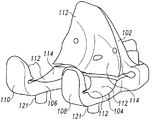
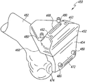
一態様によると、カスタマイズされた患者別の整形外科用器具が開示される。カスタマイズされた患者別の整形外科用器具は、対応する凸の輪郭を有する患者の大腿骨の前方側の一部を受容するよう構成されているカスタマイズされた患者別の凹の輪郭を有する骨接面(bone-facing surface)を有する本体、を含むことができる、カスタマイズされた患者別の大腿骨切断ブロックを含み得る。また、カスタマイズされた患者別の整形外科用器具は、本体から後方に延在する少なくとも1つのタブも含むことができ、少なくとも1つのタブは、対応する凸の輪郭を有する患者の大腿骨の遠位側の一部を受容するよう構成されているカスタマイズされた患者別の凹の輪郭を有する骨接面を有する。カスタマイズされた患者別の整形外科用器具は、少なくとも1つのタブの末端部から上方に延在する縁であって、対応する位置輪郭を有する患者の大腿骨の後方側の一部を受容するよう構成されているカスタマイズされた患者別の凹の輪郭を有する骨接面を有する、縁、を含むことができる。 According to one aspect, a customized patient-specific orthopedic instrument is disclosed. The customized patient-specific orthopedic instrument is a bone contact having a customized patient-specific concave profile configured to receive a portion of the anterior side of the patient's femur having a corresponding convex profile. A customized patient-specific femoral cutting block can be included that can include a body having a bone-facing surface. The customized patient-specific orthopedic instrument can also include at least one tab extending posteriorly from the body, the at least one tab being a distal portion of the patient's femur having a corresponding convex profile. A bone-facing surface having a customized patient-specific concave contour configured to receive a proximal portion. The customized patient-specific orthopedic instrument is adapted to receive a posterior portion of the patient's femur having an edge extending upwardly from the distal end of the at least one tab and having a corresponding position profile. An edge having a bone-facing surface with a customized patient-specific concave contour being configured.
いくつかの実施形態において、カスタマイズされた患者別の大腿骨切断ブロックは、本体から後方に延在する第1のタブと、本体から後方に延在する第2のタブと、を含んでもよい。第1のタブ及び第2のタブのそれぞれは、対応する凸の輪郭を有する患者の大腿骨の遠位端のそれぞれの部分を受容するよう構成されているカスタマイズされた患者別の凹の輪郭を有することができ、第1のタブ及び第2のタブは、それらの間に開口部を画定する。いくつかの実施形態において、カスタマイズされた患者別の大腿骨切断ブロックは、第1のタブの末端部から上方に延在する第1の縁と、第2のタブの末端部から上方に延在する第2の縁と、を含んでもよく、第1のタブ及び第2のタブのそれぞれは、対応する凸の輪郭を有する患者の大腿骨の後方側のそれぞれの部分を受容するよう構成されているカスタマイズされた患者別の凹の輪郭を有する。 In some embodiments, the customized patient-specific femoral cutting block may include a first tab extending posteriorly from the body and a second tab extending posteriorly from the body. Each of the first tab and the second tab has a customized patient-specific concave profile configured to receive a respective portion of the distal end of the patient's femur having a corresponding convex profile. The first tab and the second tab may define an opening therebetween. In some embodiments, the customized patient-specific femoral cutting block includes a first edge extending upward from the distal end of the first tab and an upward extending from the distal end of the second tab. Each of the first tab and the second tab is configured to receive a respective portion of the posterior side of the patient's femur having a corresponding convex profile. Has a customized patient-specific concave contour.
いくつかの実施形態において、第1のタブは本体から第1の距離だけ後方に延在してもよく、第2のタブは本体から第2の距離だけ後方に延在してもよく、第1及び第2の距離は実質的に異なる。いくつかの実施形態において、カスタマイズされた患者別の大腿骨切断ブロックの本体は垂直面を画定してもよく、第1のタブ及び第2のタブは本体から垂直面に対して斜めに延在してもよい。加えて、いくつかの実施形態において、カスタマイズされた患者別の大腿骨切断ブロックの本体は、その中に画定された切断スロットを含んでもよく、切断スロットは、外科医が切断スロットを使用して、患者の大腿骨に遠位切断を実施できるように位置決めされる。 In some embodiments, the first tab may extend backward from the body by a first distance, the second tab may extend backward from the body by a second distance, The first and second distances are substantially different. In some embodiments, the body of the customized patient-specific femoral cutting block may define a vertical plane, and the first tab and the second tab extend obliquely from the body relative to the vertical plane. May be. In addition, in some embodiments, the body of the customized patient-specific femoral cutting block may include a cutting slot defined therein, the cutting slot being used by the surgeon using the cutting slot, Positioned so that a distal cut can be made to the patient's femur.
いくつかの実施形態において、カスタマイズされた患者別の大腿骨切断ブロックは、本体に連結される切断ガイドを含んでもよく、切断ガイドはその中に画定された切断スロットを有し、切断ガイドは、本体とは異なる材料から形成されており、外科医が切断スロットを使用して患者の大腿骨に遠位切断を実施できるように位置決めされる。いくつかの実施形態において、切断ガイドは金属材料から形成されており、カスタマイズされた患者別の大腿骨切断ブロックの本体に外側被覆されてもよい。 In some embodiments, the customized patient-specific femoral cutting block may include a cutting guide coupled to the body, the cutting guide having a cutting slot defined therein, the cutting guide comprising: It is formed from a different material than the body and is positioned so that the surgeon can make a distal cut to the patient's femur using the cutting slot. In some embodiments, the cutting guide is formed from a metallic material and may be overcoated on the body of a customized patient-specific femoral cutting block.
いくつかの実施形態において、カスタマイズされた患者別の大腿骨切断ブロックは、本体に連結される複数個の前方ガイドピン軸受筒を含むことができ、前方ガイドピン軸受筒のそれぞれは、本体とは異なる材料から形成されており、前方ガイドピン軸受筒を通って画定された通路を有し、この通路は、対応するガイドピンを受容するように寸法決めされている。いくつかの実施形態において、カスタマイズされた患者別の大腿骨切断ブロックの本体は、この本体を通って延在する複数個の通路を含むことができ、複数個の前方ガイドピン軸受筒のそれぞれは、複数個の通路のうちの対応する通路に受容され、各前方ガイドピン軸受筒の骨接末端部は本体の骨接面に対して引っ込むように位置決めされる。 In some embodiments, a customized patient-specific femoral cutting block can include a plurality of anterior guide pin bearings coupled to the body, each of the anterior guide pin bearings being a body. Formed from different materials and having a passage defined through the front guide pin bearing, the passage is sized to receive a corresponding guide pin. In some embodiments, the body of the customized patient-specific femoral cutting block can include a plurality of passages extending through the body, each of the plurality of anterior guide pin bushings. , Received in a corresponding one of the plurality of passages, and the bone contact end portion of each front guide pin bearing cylinder is positioned so as to be retracted with respect to the bone contact surface of the main body.
いくつかの実施形態において、複数個の通路のうちの1つは、残りの複数個の通路に対して斜めであってもよい。実施形態のいくつかにおいて、カスタマイズされた患者別の大腿骨切断ブロックの本体の通路のそれぞれは、骨接面上に座ぐりされ(counterbored)てもよい。いくつかの実施形態において、カスタマイズされた患者別の大腿骨切断ブロックは、少なくとも1つのタブに連結される遠位ガイドピン軸受筒を含むことができ、遠位ガイドピン軸受筒は、少なくとも1つのタブとは異なる材料から形成されており、遠位ガイドピン軸受筒を通って画定された通路を有し、この通路は、対応するガイドピンを受容するように寸法決めされている。いくつかの実施形態において、カスタマイズされた患者別の大腿骨切断ブロックの本体は、その中に画定された開口部を含んでもよく、開口部は、切断ガイドから複数個の前方ガイドピン軸受筒のそれぞれの最上点より上の本体上の点まで上方に延在する。 In some embodiments, one of the plurality of passages may be oblique to the remaining plurality of passages. In some embodiments, each of the passages in the body of the customized patient-specific femoral cutting block may be counterbored on the bone interface. In some embodiments, the customized patient-specific femoral cutting block can include a distal guide pin barrel coupled to at least one tab, wherein the distal guide pin bearing barrel includes at least one It is formed of a different material than the tab and has a passage defined through the distal guide pin bearing that is dimensioned to receive a corresponding guide pin. In some embodiments, the body of the customized patient-specific femoral cutting block may include an opening defined therein, wherein the opening extends from the cutting guide to a plurality of anterior guide pin bushings. It extends upward to a point on the body above each top point.
いくつかの実施形態において、少なくとも1つのタブは、少なくとも1つのタブの骨接側にわたって横方向に延在する溝を含んでもよく、溝及び切断ガイドは、横断面を画定する。いくつかの実施形態において、カスタマイズされた患者別の大腿骨切断ブロックは、本体から前方に延在する柱を含んでもよく、柱は、その中に画定された通路を含み、この通路は、柱を通って本体の骨接面まで延在しており、対応するガイドピンを受容するように寸法決めされる。いくつかの実施形態において、カスタマイズされた患者別の大腿骨切断ブロックの本体は、骨接面と反対の外面を含んでもよく、外面は陥凹部を含む。いくつかの実施形態において、カスタマイズされた患者別の大腿骨切断ブロックは、本体から延在する弓形ブラケットを含んでもよく、弓形ブラケットは、対応する凸の輪郭を有する患者の大腿骨の後方側の一部を受容するよう構成された凹の輪郭を有する後方骨接面を含む。加えて、いくつかの実施形態において、カスタマイズされた患者別の大腿骨切断ブロックの本体は、骨接面と反対の外面を含んでもよい。外面は、外科医の指の末端部を受容するように寸法決めされた陥凹部を含むことができる。陥凹部は、カスタマイズされた患者別の大腿骨切断ブロックを患者の大腿骨に連結するために圧力が印加される本体上の場所に対応してもよい。 In some embodiments, the at least one tab may include a groove that extends laterally across the osteophyte side of the at least one tab, and the groove and the cutting guide define a cross-section. In some embodiments, the customized patient-specific femoral cutting block may include a column extending forward from the body, the column including a passage defined therein, the passage including the column. Extends through the bone interface of the body and is sized to receive a corresponding guide pin. In some embodiments, the body of the customized patient-specific femoral cutting block may include an outer surface opposite the bone contacting surface, the outer surface including a recess. In some embodiments, the customized patient-specific femoral cutting block may include an arcuate bracket extending from the body, the arcuate bracket being a posterior side of the patient's femur having a corresponding convex profile. A posterior bone interface having a concave profile configured to receive a portion. In addition, in some embodiments, the body of a customized patient-specific femoral cutting block may include an outer surface opposite the bone contacting surface. The outer surface can include a recess dimensioned to receive the distal end of the surgeon's finger. The recess may correspond to a location on the body where pressure is applied to connect the customized patient-specific femoral cutting block to the patient's femur.
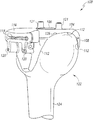
別の態様によると、カスタマイズされた患者別の整形外科用器具は、カスタマイズされた患者別の脛骨切断ブロックを含むことができ、この脛骨切断ブロックは、対応する輪郭を有する患者の脛骨の前方側の一部及び対応する輪郭を有する患者の脛骨の内側の一部を受容するよう構成されているカスタマイズされた患者別の凹の輪郭を有する骨接面を有する、本体であって、患者の脛骨のこれらの一部が本体のカスタマイズされた患者別の凹の輪郭に受容される際に、本体の垂直に延在する二等分面と患者の脛骨の二等分矢状面との間にゼロを超える角度が定められる、本体、を含んでもよい。また、本体は、本体から後方に延在する少なくとも1つのタブであって、対応する輪郭を有する患者の脛骨の近位側の一部を受容するよう構成されているカスタマイズされた患者別の凹の輪郭を有する骨接面を有する、少なくとも1つのタブ、も含むことができる。 According to another aspect, a customized patient-specific orthopedic instrument can include a customized patient-specific tibial cutting block, wherein the tibial cutting block is an anterior side of the patient's tibia having a corresponding contour. A body having a bone-facing surface having a customized patient-specific concave contour configured to receive a portion of the inner portion of the patient's tibia having a portion and a corresponding contour, the patient's tibia When these parts of the body are received in the customized patient-specific concave contour of the body, between the vertically extending bisector of the body and the bisected sagittal surface of the patient's tibia A body in which an angle greater than zero is defined. The body also has at least one tab extending posteriorly from the body, the customized patient-specific recess configured to receive a proximal portion of the patient's tibia having a corresponding contour. And at least one tab having a bone-facing surface having a contour of
いくつかの実施形態において、カスタマイズされた患者別の脛骨切断ブロックは、本体から後方に延在する第1のタブと、本体から後方に延在する第2のタブと、を含んでもよく、第1のタブ及び第2のタブのそれぞれは、対応する輪郭を有する患者の脛骨の近位端のそれぞれの部分を受容するよう構成されているカスタマイズされた患者別の凹の輪郭を有する、骨接面を有し、第1のタブ及び第2のタブは、それらの間に開口部を画定する。いくつかの実施形態において、第1のタブ及び第2のタブのそれぞれは、その中に画定されている、取り囲まれた細長い開口部を含んでもよい。 In some embodiments, the customized patient-specific tibial cutting block may include a first tab extending posteriorly from the body and a second tab extending posteriorly from the body. Each of the one tab and the second tab has a customized patient-specific concave contour configured to receive a respective portion of the proximal end of the patient's tibia having a corresponding contour. The first tab and the second tab define an opening therebetween. In some embodiments, each of the first tab and the second tab may include an enclosed elongated opening defined therein.
いくつかの実施形態において、カスタマイズされた患者別の脛骨切断ブロックの本体は、上端と、本体の骨接面と反対の外面と、を含んでもよい。上端は、その中に画定されたノッチを含むことができ、このノッチは、本体の外面から骨接面に延在する。いくつかの実施形態において、第1のタブは、本体から第1の距離だけ後方に延在してもよく、第2のタブは、本体から第2の距離だけ後方に延在してもよく、第1及び第2の距離は実質的に異なる。 In some embodiments, the body of the customized patient-specific tibial cutting block may include an upper end and an outer surface opposite the bone contacting surface of the body. The upper end can include a notch defined therein that extends from the outer surface of the body to the bone contacting surface. In some embodiments, the first tab may extend backward from the body by a first distance and the second tab may extend backward from the body by a second distance. The first and second distances are substantially different.
いくつかの実施形態において、カスタマイズされた患者別の脛骨切断ブロックの本体は、垂直面を画定してもよく、第1のタブ及び第2のタブは、本体から垂直面に対して斜めに延在する。いくつかの実施形態において、第1のタブが最大厚さを有してもよく、第2のタブが最大厚さを有してもよく、第1のタブの最大厚さは、第2のタブの最大厚さを超える。いくつかの実施形態において、カスタマイズされた患者別の脛骨切断ブロックの本体は、その中に画定された切断スロットを含んでもよく、切断スロットは、外科医が切断スロットを使用して患者の大腿骨に近位切断を実施できるように位置決めされる。 In some embodiments, the body of the customized patient-specific tibial cutting block may define a vertical plane, and the first tab and the second tab extend obliquely from the body relative to the vertical plane. Exists. In some embodiments, the first tab may have a maximum thickness, the second tab may have a maximum thickness, and the maximum thickness of the first tab may be a second thickness. Exceeds the maximum thickness of the tab. In some embodiments, the body of the customized patient-specific tibial cutting block may include a cutting slot defined therein, the cutting slot being used by the surgeon to the patient's femur using the cutting slot. Positioned so that a proximal cut can be made.
いくつかの実施形態において、カスタマイズされた患者別の脛骨切断ブロックは、本体に連結される切断ガイドを含んでもよく、切断ガイドは、その中に画定された切断スロットを有し、切断ガイドは、本体とは異なる材料から形成されており、外科医が切断スロットを使用して患者の大腿骨に遠位切断を実施できるように位置決めされる。いくつかの実施形態において、切断ガイドは金属材料から形成されており、カスタマイズされた患者別の脛骨切断ブロックの本体に外側被覆されてもよい。いくつかの実施形態において、カスタマイズされた患者別の脛骨切断ブロックは、骨接面と反対の外面及びこの外面から外側に延在する出っ張りを含んでもよく、この出っ張りは、切断ガイドの切断スロットの底面と同一平面である上面を有する。 In some embodiments, the customized patient-specific tibial cutting block may include a cutting guide coupled to the body, the cutting guide having a cutting slot defined therein, the cutting guide comprising: It is formed from a different material than the body and is positioned so that the surgeon can make a distal cut to the patient's femur using the cutting slot. In some embodiments, the cutting guide is formed from a metallic material and may be overcoated on the body of a customized patient-specific tibial cutting block. In some embodiments, the customized patient-specific tibial cutting block may include an outer surface opposite the bone-facing surface and a ledge extending outwardly from the outer surface, the bulge being in a cutting slot of the cutting guide. It has a top surface that is flush with the bottom surface.
いくつかの実施形態において、カスタマイズされた患者別の脛骨切断ブロックは、本体に連結される複数個の前方ガイドピン軸受筒を含んでもよく、前方ガイドピン軸受筒のそれぞれは、本体とは異なる材料から形成されており、前方ガイドピン軸受筒を通って画定された通路を有し、この通路は、対応するガイドピンを受容するように寸法決めされている。いくつかの実施形態において、カスタマイズされた患者別の脛骨切断ブロックの本体は、この本体を通って延在する複数個の通路を含み、複数個の前方ガイドピン軸受筒のそれぞれは、複数個の通路のうちの対応する通路に受容され、各前方ガイドピン軸受筒の骨接末端部が本体の骨接面に対して引っ込むように位置決めされる。いくつかの実施形態において、複数個の通路のうちの1つは、残りの複数個の通路に対して斜めであってもよい。 In some embodiments, the customized patient-specific tibial cutting block may include a plurality of anterior guide pin bearings coupled to the body, each of the anterior guide pin bearings being a different material than the body. And has a passage defined through the front guide pin bearing barrel, the passage being sized to receive a corresponding guide pin. In some embodiments, the body of the customized patient-specific tibial cutting block includes a plurality of passages extending through the body, and each of the plurality of anterior guide pin bushings includes a plurality of Receiving in the corresponding one of the passages, the bone contact end of each front guide pin bearing barrel is positioned so as to retract relative to the bone contact surface of the body. In some embodiments, one of the plurality of passages may be oblique to the remaining plurality of passages.
いくつかの実施形態において、カスタマイズされた患者別の脛骨切断ブロックの本体の通路のそれぞれは、骨接面上に座ぐりされてもよい。加えて、いくつかの実施形態において、カスタマイズされた患者別の脛骨切断ブロックは、少なくとも1つのタブに連結される近位ガイドピン軸受筒を含むことができ、近位ガイドピン軸受筒は、少なくとも1つのタブとは異なる材料から形成されており、近位ガイドピン軸受筒を通って画定された通路を有し、この通路は、対応するガイドピンを受容するように寸法決めされている。いくつかの実施形態において、カスタマイズされた患者別の脛骨切断ブロックの本体は、骨接面と反対の外面を含んでもよく、外面は、陥凹部を含む。 In some embodiments, each of the passages of the body of the customized patient-specific tibial cutting block may be seated on the bone interface. In addition, in some embodiments, a customized patient-specific tibial cutting block can include a proximal guide pin bushing coupled to at least one tab, wherein the proximal guide pin bearing barrel is at least The tab is formed of a different material and has a passage defined through the proximal guide pin bearing barrel, the passage being sized to receive a corresponding guide pin. In some embodiments, the body of the customized patient-specific tibial cutting block may include an outer surface opposite the bone contacting surface, the outer surface including a recess.
いくつかの実施形態において、本体の垂直に延在する二等分面と患者の脛骨の二等分矢状面との間に定められる角度は、10度〜30度であってもよい。加えて、いくつかの実施形態において、本体の垂直に延在する二等分面と患者の脛骨の二等分矢状面との間に定められる角度は、約20度であってもよい。いくつかの実施形態において、タブは、前方から後方の方向に減少する厚さを有してもよい。いくつかの実施形態において、少なくとも1つのタブは、矢状面内に凹断面を有することができる上面を有する。いくつかの実施形態において、本体の骨接面のカスタマイズされた患者別の凹の輪郭の一部は、合成角を実質的に定めることができる。いくつかの実施形態において、少なくとも1つのタブの骨接面は、周囲に周縁を画定する中央凹部を含んでもよく、少なくとも1つのタブの骨接面のカスタマイズされた患者別の凹の輪郭は、周縁上に画定される。 In some embodiments, the angle defined between the vertically extending bisector of the body and the bisected sagittal plane of the patient's tibia may be between 10 degrees and 30 degrees. In addition, in some embodiments, the angle defined between the vertically extending bisector of the body and the bisected sagittal plane of the patient's tibia may be about 20 degrees. In some embodiments, the tab may have a thickness that decreases from anterior to posterior direction. In some embodiments, the at least one tab has a top surface that can have a concave cross-section in the sagittal plane. In some embodiments, a portion of the customized patient-specific concave profile of the bone-facing surface of the body can substantially define a composite angle. In some embodiments, the bone-facing surface of the at least one tab may include a central recess that defines a perimeter around the customized patient-specific concave contour of the bone-facing surface of the at least one tab, Defined on the periphery.
別の態様によると、カスタマイズされた患者別の整形外科用器具が開示される。カスタマイズされた患者別の整形外科用器具は、カスタマイズされた患者別の切断ブロックである。カスタマイズされた患者別の切断ブロックは、対応する輪郭を有する患者の骨の一部を受容するよう構成された凹の輪郭を含む骨接面を有することができ、凹の輪郭は、患者の骨上に存在する軟骨の厚さに基づいて、患者の骨の輪郭に対して所定の量だけ拡大縮小される(scaled)。 According to another aspect, a customized patient-specific orthopedic instrument is disclosed. The customized patient-specific orthopedic instrument is a customized patient-specific cutting block. The customized patient-specific cutting block can have a bone-facing surface that includes a concave contour configured to receive a portion of the patient's bone having a corresponding contour, the concave contour being Based on the thickness of the existing cartilage, the patient's bone contour is scaled by a predetermined amount.
一態様によると、カスタマイズされた患者別の整形外科用器具が開示される。カスタマイズされた患者別の整形外科用器具は、カスタマイズされた患者別の切断ブロックを含む。カスタマイズされた患者別の切断ブロックは、前方本体部品と、前方本体部品から分離されている末端本体部品と、前方本体部品及び末端本体部品を互いに固定する、いくつかの留め具と、を含むことができる。いくつかの実施形態において、カスタマイズされた患者別の切断ブロックは、カスタマイズされた患者別の大腿骨切断ブロックであってもよい。加えて、いくつかの実施形態において、カスタマイズされた患者別の切断ブロックは、カスタマイズされた患者別の脛骨切断ブロックであってもよい。 According to one aspect, a customized patient-specific orthopedic instrument is disclosed. The customized patient-specific orthopedic instrument includes a customized patient-specific cutting block. The customized patient-specific cutting block includes an anterior body part, a distal body part that is separated from the anterior body part, and a number of fasteners that secure the anterior body part and the distal body part together. Can do. In some embodiments, the customized patient-specific cutting block may be a customized patient-specific femoral cutting block. In addition, in some embodiments, the customized patient-specific cutting block may be a customized patient-specific tibial cutting block.
前方本体部品は、骨接面、骨接面と反対の外面、及び切断ガイド、を含むことができる。骨接面は、対応する輪郭を有する患者の骨の前方側の一部を受容するよう構成されているカスタマイズされた患者別の凹の輪郭を有することができる。いくつかの実施形態において、カスタマイズされた患者別の切断ブロックの前方本体部品は、外面から骨接面に延在する一対のガイドピン穴を更に含んでもよい。いくつかの実施形態において、前方本体部品の切断ガイドは、捕捉切断ガイドであってもよい。 The anterior body component can include a bone contacting surface, an outer surface opposite the bone contacting surface, and a cutting guide. The bone-facing surface may have a customized patient-specific concave contour configured to receive a portion of the anterior side of the patient's bone having a corresponding contour. In some embodiments, the anterior body part of the customized patient-specific cutting block may further include a pair of guide pin holes extending from the outer surface to the bone contacting surface. In some embodiments, the cutting guide of the front body part may be a capture cutting guide.
末端本体部品は、骨接面、及び骨接面と反対の外面、を含むことができる。骨接面は、対応する輪郭を有する患者の骨の一部を受容するよう構成されているカスタマイズされた患者別の凹の輪郭を有し得る。いくつかの実施形態において、末端本体部品は、外面から骨接面に延在する、その中に画定された一対のガイドピン穴を含んでもよい。 The end body component can include a bone contacting surface and an outer surface opposite the bone contacting surface. The bone-facing surface may have a customized patient-specific concave contour configured to receive a portion of the patient's bone having a corresponding contour. In some embodiments, the distal body part may include a pair of guide pin holes defined therein that extend from the outer surface to the bone contacting surface.
いくつかの実施形態において、いくつかの留め具は、いくつかのピンを含む。前方本体部品及び末端本体部品は、それぞれがいくつかの穴を有することができる。前方本体部品及び末端本体部品を互いに固定するために、いくつかのピンは、前方本体部品内に画定された、いくつかの穴、及び末端本体部品内に画定された、いくつかの穴に位置決めされてもよい。 In some embodiments, some fasteners include several pins. The front body part and the end body part can each have several holes. In order to secure the front body part and the end body part to each other, several pins are positioned in several holes defined in the front body part and in several holes defined in the end body part. May be.
別の態様によると、患者の骨に整形外科手術を実施する方法が開示される。本方法は、カスタマイズされた患者別の切断ブロックの前方本体部品を、切開部を通して挿入する工程を含むことができる。本方法は、カスタマイズされた患者別の切断ブロックの末端本体部品を、切開部を通して挿入する工程であって、末端本体部品が、前方本体部品から分離されている、工程を含むことができる。本方法は、前方本体部品及び末端本体部品を両方の部品の挿入後に互いに固定し、組み立てられ、カスタマイズされた患者別の切断ブロックを作り出す工程を含むことができる。いくつかの実施形態において、いくつかのピンを用いて、前方本体部品及び末端本体部品が互いに固定されてもよい。 According to another aspect, a method for performing orthopedic surgery on a patient's bone is disclosed. The method can include inserting an anterior body part of a customized patient-specific cutting block through the incision. The method can include inserting a customized patient-specific cutting block end body part through the incision, wherein the end body part is separated from the anterior body part. The method may include securing the anterior body part and the end body part together after insertion of both parts and assembled to create a customized patient-specific cutting block. In some embodiments, a number of pins may be used to secure the front body part and the end body part together.
本方法は、組み立てられ、カスタマイズされた患者別の切断ブロックを、患者の骨に接触させて位置決めする工程と、組み立てられ、カスタマイズされた患者別の切断ブロックを用いて、患者の骨に切り目を入れる工程と、を含むことができる。いくつかの実施形態において、本方法は、組み立てられ、カスタマイズされた患者別の切断ブロックを、患者の大腿骨に接触させて位置決めする工程を含んでもよい。本方法は、組み立てられ、カスタマイズされた患者別の切断ブロックを用いて、患者の大腿骨に切り目を入れる工程も含むことができる。加えて、いくつかの実施形態において、本方法は、組み立てられ、カスタマイズされた患者別の切断ブロックを、患者の脛骨に接触させて位置決めする工程を含んでもよい。本方法は、組み立てられ、カスタマイズされた患者別の切断ブロックを用いて、患者の脛骨に切り目を入れる工程も含むことができる。いくつかの実施形態において、本方法は、患者の骨に切り目を入れる工程の前に、一対のガイドピンを、組み立てられ、カスタマイズされた患者別の切断ブロック内に画定された一対のガイドピン穴に挿入する工程も含むことができる。 The method includes positioning an assembled and customized patient-specific cutting block in contact with the patient's bone, and using the assembled and customized patient-specific cutting block to cut the patient's bone. Adding. In some embodiments, the method may include positioning an assembled and customized patient-specific cutting block in contact with the patient's femur. The method can also include incising the patient's femur using an assembled and customized patient-specific cutting block. In addition, in some embodiments, the method may include positioning an assembled and customized patient-specific cutting block in contact with the patient's tibia. The method may also include incising the patient's tibia using an assembled and customized patient-specific cutting block. In some embodiments, the method includes a pair of guide pins that are assembled and defined in a customized patient-specific cutting block prior to the step of nicking the patient's bone. A step of inserting into the substrate.
別の態様によると、カスタマイズされた患者別の整形外科用器具が開示される。カスタマイズされた患者別の整形外科用器具は、本体を含むカスタマイズされた患者別の切断ブロックを有することができる。いくつかの実施形態において、カスタマイズされた患者別の切断ブロックは、カスタマイズされた患者別の大腿骨切断ブロックであり得る。加えて、いくつかの実施形態において、カスタマイズされた患者別の切断ブロックは、カスタマイズされた患者別の脛骨切断ブロックであり得る。 According to another aspect, a customized patient-specific orthopedic instrument is disclosed. The customized patient-specific orthopedic instrument can have a customized patient-specific cutting block that includes a body. In some embodiments, the customized patient-specific cutting block may be a customized patient-specific femoral cutting block. In addition, in some embodiments, the customized patient-specific cutting block may be a customized patient-specific tibial cutting block.
本体は、骨接面、骨接面と反対の外面、及び非捕捉切断ガイド、を有することができる。骨接面は、対応する輪郭を有する患者の骨の前方側の一部を受容するよう構成されているカスタマイズされた患者別の凹の輪郭を有してもよい。いくつかの実施形態において、カスタマイズされた患者別の切断ブロックの本体は、外面から骨接面に延在する、その中に画定された一対のガイドピン穴を有してもよい。非捕捉切断ガイドは、外面から骨接面に延在する側壁によって画定されてもよい。 The body can have a bone-facing surface, an outer surface opposite the bone-facing surface, and a non-capturing cutting guide. The bone-facing surface may have a customized patient-specific concave contour configured to receive a portion of the anterior side of the patient's bone having a corresponding contour. In some embodiments, the body of the customized patient-specific cutting block may have a pair of guide pin holes defined therein that extend from the outer surface to the bone contacting surface. The non-capturing cutting guide may be defined by a sidewall that extends from the outer surface to the bone-facing surface.
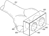
一態様によると、カスタマイズされた患者別の整形外科用器具が開示される。カスタマイズされた患者別の整形外科用器具は、前方骨接面、及び遠位骨接面、を有する、切断ブロックを含むことができる。 According to one aspect, a customized patient-specific orthopedic instrument is disclosed. The customized patient-specific orthopedic instrument can include a cutting block having an anterior bone contacting surface and a distal bone contacting surface.
前方骨接面は、患者の骨の前方側の一部を受容するよう構成されてもよい。前方骨接面は、骨切断ブロックの最近位エッジから離れる方向に、切断ブロックの遠位骨接面に向かって遠位に延在する第1の平面を含むことができる。前方骨接面は、第1の平面から離れて遠位に延在する、カスタマイズされた患者別の前方の凹の輪郭表面を含むことができ、カスタマイズされた患者別の前方の凹の輪郭表面は、対応する輪郭を有する患者の骨の前方側の一部を受容するよう構成されている。また、前方骨接面は、カスタマイズされた患者別の前方の凹の輪郭表面から遠位骨接面に向かって遠位に延在する第2の平面、を含むことができる。 The anterior bone interface may be configured to receive a portion of the anterior side of the patient's bone. The anterior bone contacting surface can include a first plane that extends distally toward the distal bone contacting surface of the cutting block in a direction away from the proximal edge of the bone cutting block. The anterior bone contacting surface can include a customized patient-specific anterior concave contour surface extending distally away from the first plane, the customized patient-specific anterior concave contour surface Is configured to receive a portion of the anterior side of the patient's bone having a corresponding contour. The anterior bone interface can also include a second plane extending distally from the customized patient-specific anterior concave contour surface toward the distal bone interface.
遠位骨接面は、患者の骨の遠位側の一部を受容するよう構成されてもよい。遠位骨接面は、骨切断ブロックの前方骨接面から離れる方向に、切断ブロックの最後方エッジに向かって後方に延在する第1の平面を含むことができる。遠位骨接面は、第1の平面から離れて後方に延在する、カスタマイズされた患者別の遠位の凹の輪郭表面を含むことができ、カスタマイズされた患者別の遠位の凹の輪郭表面は、対応する輪郭を有する患者の骨の遠位側の一部を受容するよう構成されている。また、遠位骨接面は、カスタマイズされた患者別の遠位の凹の輪郭表面から切断ブロックの最後方エッジに向かって後方に延在する第2の平面を含むことができる。 The distal bone interface may be configured to receive a portion of the patient's bone distally. The distal bone interface may include a first plane that extends posteriorly toward the rearmost edge of the cutting block in a direction away from the anterior bone contacting surface of the bone cutting block. The distal bone interface may include a customized patient-specific distal concave contour surface extending posteriorly away from the first plane, the customized patient-specific distal concave surface The contour surface is configured to receive a distal portion of the patient's bone having a corresponding contour. The distal bone interface may also include a second plane extending posteriorly from the customized patient-specific distal concave contour surface toward the rearmost edge of the cutting block.
いくつかの実施形態において、切断ブロックは、ほぼL字形であってもよく、前方プレート、及び前方プレートに固定され、前方プレートから離れて延在する遠位プレートを有してもよい。前方骨接面は前方プレート内に画定されてもよく、遠位骨接面は遠位プレート内に画定されてもよい。 In some embodiments, the cutting block may be generally L-shaped and may have a front plate and a distal plate fixed to the front plate and extending away from the front plate. The anterior bone contacting surface may be defined in the anterior plate and the distal bone contacting surface may be defined in the distal plate.
いくつかの実施形態において、前方プレートは、前方プレートを通って延在する遠位切断ガイドを有してもよい。加えて、いくつかの実施形態において、遠位プレートは、遠位プレートを通って延在する前方切断ガイド及び後方切断ガイドの両方を有してもよい。いくつかの実施形態において、遠位プレートは、遠位プレートを通って延在する、角を成す一対の切断ガイドを有してもよい。いくつかの実施形態において、遠位プレートは、遠位プレートを通って延在する、前方切断ガイドを有してもよい。いくつかの実施形態において、遠位プレートは、遠位プレートを通って延在する、後方切断ガイドを有してもよい。 In some embodiments, the front plate may have a distal cutting guide that extends through the front plate. In addition, in some embodiments, the distal plate may have both an anterior cutting guide and a posterior cutting guide extending through the distal plate. In some embodiments, the distal plate may have a pair of angled cutting guides extending through the distal plate. In some embodiments, the distal plate may have an anterior cutting guide that extends through the distal plate. In some embodiments, the distal plate may have a posterior cutting guide that extends through the distal plate.
いくつかの実施形態において、前方骨接面の第1の平面は、カスタマイズされた患者別の前方の凹の輪郭表面に移行してもよい。カスタマイズされた患者別の前方の凹の輪郭表面は、前方骨接面の第2の平面に移行してもよい。加えて、いくつかの実施形態において、遠位骨接面の第1の平面は、カスタマイズされた患者別の遠位の凹の輪郭表面に移行してもよい。カスタマイズされた患者別の遠位の凹の輪郭表面は、遠位骨接面の第2の平面に移行してもよい。 In some embodiments, the first plane of the anterior bone interface may transition to a customized patient-specific anterior concave contour surface. The customized patient-specific anterior concave contour surface may transition to the second plane of the anterior bone interface. In addition, in some embodiments, the first plane of the distal bone interface may transition to a customized patient-specific distal concave contour surface. The customized patient-specific distal concave contour surface may transition to the second plane of the distal bone interface.
別の態様によると、患者の骨に整形外科手術を実施する方法が開示される。本方法は、患者の骨の前方側がカスタマイズされた患者別の切断ブロックのカスタマイズされた患者別の前方の凹の輪郭表面に受容され、患者の骨の遠位側が切断ブロックのカスタマイズされた患者別の遠位の凹の輪郭表面に受容されるように、カスタマイズされた患者別の切断ブロックを患者の骨に固定する工程を含むことができる。本方法は、患者の骨の前方側上に平面が形成されるように、切断ブロックを用いて患者の骨に前方の切り目を入れる工程と、患者の骨の遠位側上に平面が形成されるように、切断ブロックを用いて患者の骨に遠位の切り目を入れる工程と、を含むことができる。本方法は、患者の骨に前方の切り目及び遠位の切り目を入れる工程の後に、患者の骨から除去される追加の骨の量を決定する工程も含むことができる。 According to another aspect, a method for performing orthopedic surgery on a patient's bone is disclosed. The method accepts the anterior side of the patient's bone in the customized patient-specific anterior contour surface of the customized patient-specific cutting block and the distal side of the patient's bone is the customized patient-specific of the cutting block. Securing a customized patient-specific cutting block to the patient's bone to be received by the distal concave contour surface of the patient. The method includes the steps of making an anterior incision in the patient's bone using a cutting block so that a plane is formed on the anterior side of the patient's bone, and a plane is formed on the distal side of the patient's bone. Cutting a distal cut into the patient's bone using a cutting block. The method can also include determining the amount of additional bone removed from the patient's bone after the step of making an anterior cut and a distal cut in the patient's bone.
本方法は、患者の骨の前方側内に形成される平面が、切断ブロックの前方骨接面内に形成される少なくとも1つの平面に接して位置決めされ、患者の骨の遠位側内に形成される平面が、切断ブロックの遠位骨接面内に形成される少なくとも1つの平面に接して位置決めされるように、カスタマイズされた患者別の切断ブロックを患者の骨に固定する工程を含むことができる。本方法は、追加の骨が患者の骨の前方側上に形成される平面から除去されるように、切断ブロックを用いて、患者の骨に追加的な前方の切り目を入れる工程、及び追加の骨が患者の骨の遠位側上に形成される平面から除去されるように、切断ブロックを用いて、患者の骨に追加的な遠位の切り目を入れる工程、のうちの少なくとも1つを行う工程を更に含むことができる。 In the method, a plane formed in the anterior side of the patient's bone is positioned against at least one plane formed in the anterior bone contacting surface of the cutting block and formed in the distal side of the patient's bone. Securing the customized patient-specific cutting block to the patient's bone so that the plane being applied is positioned against at least one plane formed in the distal bone interface of the cutting block Can do. The method includes using the cutting block to make an additional anterior cut in the patient's bone such that the additional bone is removed from the plane formed on the anterior side of the patient's bone, and the additional Using the cutting block to make an additional distal incision in the patient's bone such that the bone is removed from the plane formed on the distal side of the patient's bone, at least one of The process of performing can be further included.
いくつかの実施形態において、本方法は、患者の大腿骨の前方側が、切断ブロックのカスタマイズされた患者別の前方の凹の輪郭表面に受容され、患者の大腿骨の遠位側が、切断ブロックのカスタマイズされた患者別の遠位の凹の輪郭表面に受容されるように、カスタマイズされた患者別の切断ブロックを患者の大腿骨に固定する工程を含むことができる。いくつかの実施形態において、本方法は、追加の骨が患者の骨の前方側上に形成される平面から除去されるように、切断ブロックを用いて、患者の骨に追加的な前方の切り目を入れる工程、及び追加の骨が患者の骨の遠位側上に形成される平面から除去されるように、切断ブロックを用いて、患者の骨に追加的な遠位の切り目を入れる工程、の両方を行う工程を含むことができる。 In some embodiments, the method includes the anterior side of the patient's femur being received in a customized patient-specific anterior concave contour surface of the cutting block and the distal side of the patient's femur is Securing the customized patient-specific cutting block to the patient's femur to be received by the customized patient-specific distal concave contour surface may be included. In some embodiments, the method uses an additional anterior cut in the patient's bone using a cutting block such that the additional bone is removed from the plane formed on the anterior side of the patient's bone. And using the cutting block to make an additional distal incision in the patient's bone so that the additional bone is removed from the plane formed on the distal side of the patient's bone, The process of performing both of these can be included.
別の態様によると、カスタマイズされた患者別の整形外科用器具が開示される。カスタマイズされた患者別の整形外科用器具は、対応する輪郭を有する患者の骨の前方側の一部を受容するよう構成されているカスタマイズされた患者別の前方の凹の輪郭表面を有する切断ブロックを含むことができる。切断ブロックは、対応する輪郭を有する患者の骨の遠位側の一部を受容するよう構成されているカスタマイズされた患者別の遠位の凹の輪郭表面を有することができる。切断ブロックは、対応する輪郭を有する患者の骨の後方側の一部を受容するよう構成されているカスタマイズされた患者別の後方の凹の輪郭表面を有することもできる。 According to another aspect, a customized patient-specific orthopedic instrument is disclosed. A customized patient-specific orthopedic instrument is a cutting block having a customized patient-specific anterior concave contour surface configured to receive a portion of the anterior side of the patient's bone having a corresponding contour Can be included. The cutting block may have a customized patient-specific distal concave contour surface configured to receive a distal portion of the patient's bone having a corresponding contour. The cutting block may also have a customized patient-specific posterior concave contour surface configured to receive a portion of the posterior side of the patient's bone having a corresponding contour.
いくつかの実施形態において、切断ブロックは、ほぼU字形であってよく、前方プレート、遠位プレート、及び後方プレートを有することができる。前方骨接面は前方プレート内に画定されてもよく、遠位骨接面は遠位プレート内に画定されてもよく、後方骨接面は後方プレート内に画定される。 In some embodiments, the cutting block can be generally U-shaped and can have an anterior plate, a distal plate, and a posterior plate. The anterior bone contacting surface may be defined in the anterior plate, the distal bone contacting surface may be defined in the distal plate, and the posterior bone contacting surface is defined in the posterior plate.
いくつかの実施形態において、前方プレートは、前方プレートを通って延在する、遠位切断ガイドを有し得る。加えて、いくつかの実施形態において、遠位プレートは、遠位プレートを通って延在する前方切断ガイド及び後方切断ガイドの両方を有してもよい。いくつかの実施形態において、遠位プレートは、遠位プレートを通って延在する、角を成す一対の切断ガイドを有してもよい。いくつかの実施形態において、遠位プレートは、遠位プレートを通って延在する前方切断ガイドを有し得る。いくつかの実施形態において、遠位プレートは、遠位プレートを通って延在する後方切断ガイドを有してもよい。 In some embodiments, the anterior plate can have a distal cutting guide that extends through the anterior plate. In addition, in some embodiments, the distal plate may have both an anterior cutting guide and a posterior cutting guide extending through the distal plate. In some embodiments, the distal plate may have a pair of angled cutting guides extending through the distal plate. In some embodiments, the distal plate can have an anterior cutting guide that extends through the distal plate. In some embodiments, the distal plate may have a posterior cutting guide extending through the distal plate.
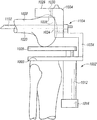
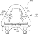
一態様によると、整形外科用器具アセンブリが開示される。整形外科用器具アセンブリは、カスタマイズされた患者別の大腿骨切断ブロックと、カスタマイズされた患者別の脛骨切断ブロックと、カスタマイズされた患者別の大腿骨切断ブロックとカスタマイズされた患者別の脛骨切断ブロックとの間に位置決めされる機械的連結部と、を含むことができる。カスタマイズされた患者別の大腿骨切断ブロックは、対応する輪郭を有する患者の遠位大腿骨の一部を受容するよう構成されているカスタマイズされた患者別の凹の輪郭表面、及び切断ガイド、を含むことができる。カスタマイズされた患者別の脛骨切断ブロックは、対応する輪郭を有する患者の近位脛骨の一部を受容するよう構成されているカスタマイズされた患者別の凹の輪郭表面、及び切断ガイド、を含むことができる。機械的連結部は、カスタマイズされた患者別の大腿骨切断ブロック及びカスタマイズされた患者別の脛骨切断ブロックを、互いから離れるように、また互いに向かって、移動させるように動作可能であってもよい。 According to one aspect, an orthopedic instrument assembly is disclosed. Orthopedic instrument assembly includes customized patient-specific femoral cutting block, customized patient-specific tibial cutting block, customized patient-specific femoral cutting block and customized patient-specific tibial cutting block And a mechanical link positioned between the two. The customized patient-specific femoral cutting block includes a customized patient-specific concave contour surface configured to receive a portion of the patient's distal femur having a corresponding contour, and a cutting guide. Can be included. The customized patient-specific tibial cutting block includes a customized patient-specific concave contour surface configured to receive a portion of the patient's proximal tibia having a corresponding contour, and a cutting guide. Can do. The mechanical linkage may be operable to move the customized patient-specific femoral cutting block and the customized patient-specific tibial cutting block away from each other and toward each other. .
いくつかの実施形態において、機械的連結部は、いくつかのねじ付きシャフトを含んでもよい。ねじ付きシャフトの第1の方向への回転は、カスタマイズされた患者別の大腿骨切断ブロック及びカスタマイズされた患者別の脛骨切断ブロックを互いから離れるように移動させることができる。ねじ付きシャフトの第2の反対方向への回転は、カスタマイズされた患者別の大腿骨切断ブロック及びカスタマイズされた患者別の脛骨切断ブロックを互いに向かって移動させることができる。 In some embodiments, the mechanical connection may include a number of threaded shafts. Rotation of the threaded shaft in the first direction can move the customized patient-specific femoral cutting block and the customized patient-specific tibial cutting block away from each other. Rotation of the threaded shaft in the second opposite direction can move the customized patient-specific femoral cutting block and the customized patient-specific tibial cutting block toward each other.
いくつかの実施形態において、機械的連結部は、いくつかのねじ付きシャフトに連結されるいくつかの蝶ねじを含んでもよい。蝶ねじの第1の方向への回転は、ねじ付きシャフトを第1の方向に回転させることができる。蝶ねじの第2の方向への回転は、ねじ付きシャフトを第2の方向に回転させることができる。 In some embodiments, the mechanical coupling may include a number of thumb screws that are coupled to a number of threaded shafts. Rotating the thumbscrew in the first direction can cause the threaded shaft to rotate in the first direction. Rotating the thumbscrew in the second direction can cause the threaded shaft to rotate in the second direction.
いくつかの実施形態において、機械的連結部は、いくつかの蝶ねじを含んでもよい。蝶ねじの第1の方向への回転は、カスタマイズされた患者別の大腿骨切断ブロック及びカスタマイズされた患者別の脛骨切断ブロックを互いから離れるように移動させることができる。蝶ねじの第2の反対方向への回転は、カスタマイズされた患者別の大腿骨切断ブロック及びカスタマイズされた患者別の脛骨切断ブロックを互いに向かって移動させることができる。 In some embodiments, the mechanical connection may include a number of thumb screws. Rotating the thumbscrew in the first direction can move the customized patient-specific femoral cutting block and the customized patient-specific tibial cutting block away from each other. Rotating the thumbscrew in the second opposite direction can move the customized patient-specific femoral cutting block and the customized patient-specific tibial cutting block toward each other.
いくつかの実施形態において、カスタマイズされた患者別の大腿骨切断ブロック及びカスタマイズされた患者別の脛骨切断ブロックの両方は、いくつかのガイドピン穴を有する。いくつかの実施形態において、カスタマイズされた患者別の大腿骨切断ブロックの切断ガイドは、カスタマイズされた患者別の脛骨切断ブロックの切断ガイドに対してほぼ平行である。 In some embodiments, both the customized patient-specific femoral cutting block and the customized patient-specific tibial cutting block have several guide pin holes. In some embodiments, the customized patient-specific femoral cutting block cutting guide is substantially parallel to the customized patient-specific tibial cutting block cutting guide.
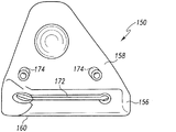
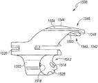
別の態様によると、整形外科用器具アセンブリは、カスタマイズされた患者別の大腿骨切断ブロックと、大腿骨切断ブロックに固定された靭帯平衡器と、を含むことができる。カスタマイズされた患者別の大腿骨切断ブロックは、対応する輪郭を有する患者の遠位大腿骨の一部を受容するよう構成されているカスタマイズされた患者別の凹の輪郭表面、及び切断ガイド、を有することができる。靭帯平衡器は、脛骨ベースプレート、及び脛骨ベースプレートに対してそれぞれが移動可能である、一対の大腿骨パドル、を有することができる。 According to another aspect, the orthopedic instrument assembly can include a customized patient-specific femoral cutting block and a ligament balancer secured to the femoral cutting block. The customized patient-specific femoral cutting block includes a customized patient-specific concave contour surface configured to receive a portion of the patient's distal femur having a corresponding contour, and a cutting guide. Can have. The ligament balancer can have a tibial base plate and a pair of femoral paddles that are each movable relative to the tibial base plate.
いくつかの実施形態において、整形外科用器具アセンブリは、大腿骨切断ブロックに固定された第1の末端部、及び靭帯平衡器に固定された第2の末端部を有する、ブラケット、を含んでもよい。加えて、いくつかの実施形態において、ブラケットの第2の末端部は、靭帯平衡器の脛骨ベースプレートに固定されてもよい。いくつかの実施形態において、ブラケットの第1の末端部は、その中に画定された一対のガイドピン穴を有してもよい。いくつかの実施形態において、ブラケットは、大腿骨切断ブロックに固定された第1の末端部、及び靭帯平衡器に固定された第2の末端部を有してもよい。ブラケットは、髄内ロッドを受容するよう構成されている受容部も有することができる。 In some embodiments, the orthopedic instrument assembly may include a bracket having a first end secured to the femoral cutting block and a second end secured to the ligament balancer. . In addition, in some embodiments, the second end of the bracket may be secured to the tibial baseplate of the ligament balancer. In some embodiments, the first end of the bracket may have a pair of guide pin holes defined therein. In some embodiments, the bracket may have a first end secured to the femoral cutting block and a second end secured to the ligament balancer. The bracket can also have a receptacle configured to receive the intramedullary rod.
いくつかの実施形態において、カスタマイズされた患者別の大腿骨切断ブロックは、患者の大腿骨の前方側の一部を受容するよう構成されているカスタマイズされた患者別の前方骨接面、及び患者の大腿骨の遠位側の一部を受容するよう構成されているカスタマイズされた患者別の遠位骨接面、を含んでもよい。いくつかの実施形態において、靭帯平衡器は、脛骨ベースプレートに固定される一対のシリンダーを有し、一対の大腿骨パドルのそれぞれは、一対のシリンダーのそれぞれ1つに受容される。 In some embodiments, the customized patient-specific femoral cutting block is a customized patient-specific anterior bone interface configured to receive a portion of the anterior side of the patient's femur, and the patient A customized patient-specific distal bone interface configured to receive a portion of the distal femur of the patient. In some embodiments, the ligament balancer has a pair of cylinders secured to the tibial baseplate, and each of the pair of femoral paddles is received in a respective one of the pair of cylinders.
別の態様によると、患者への整形外科手術の方法が開示される。本方法は、カスタマイズされた患者別の大腿骨切断ブロックを患者の大腿骨に固定する工程と、靭帯平衡器を患者の脛骨に固定する工程と、を含むことができる。本方法は、靭帯平衡器を、カスタマイズされた患者別の大腿骨切断ブロックに固定する工程を含むことができる。本方法は、靭帯平衡器を操作して、患者の大腿骨を脛骨に対して所望の位置に位置決めする工程も含むことができる。本方法は、カスタマイズされた患者別の切断ブロックを用いて、患者の大腿骨に切り目を入れる工程を更に含むことができる。 According to another aspect, a method of orthopedic surgery on a patient is disclosed. The method can include securing a customized patient-specific femoral cutting block to the patient's femur and securing a ligament balancer to the patient's tibia. The method can include securing the ligament balancer to a customized patient-specific femoral cutting block. The method can also include manipulating the ligament balancer to position the patient's femur in a desired position relative to the tibia. The method may further include incising the patient's femur using a customized patient-specific cutting block.
いくつかの実施形態において、カスタマイズされた患者別の大腿骨切断ブロックを固定する工程は、カスタマイズされた患者別の大腿骨切断ブロックを、患者の大腿骨に接触させて位置決めする工程を含んでもよい。本方法は、カスタマイズされた患者別の大腿骨切断ブロックを患者の大腿骨に固定するために、少なくとも1つのガイドピンを、カスタマイズされた患者別の大腿骨切断ブロック内に画定された少なくとも1つのガイドピン穴に挿入する工程も含むことができる。 In some embodiments, securing the customized patient-specific femoral cutting block may include positioning the customized patient-specific femoral cutting block in contact with the patient's femur. . The method includes at least one guide pin defined in the customized patient-specific femoral cutting block for securing the customized patient-specific femoral cutting block to the patient's femur. A step of inserting into the guide pin hole can also be included.
いくつかの実施形態において、本方法は、ブラケットの第1の末端部が固定された、靭帯平衡器を含むことができる。ブラケットの第2の末端部は、その中に画定された少なくとも1つのガイドピン穴を有することができる。本方法は、ブラケットの第2の末端部を、カスタマイズされた患者別の大腿骨切断ブロックに固定するために、少なくとも1つのガイドピンをブラケットの少なくとも1つのガイドピン穴内に進める工程も含むことができる。いくつかの実施形態において、本方法は、靭帯平衡器が、それに固定されたブラケットの第1の末端部を有し、ブラケットの第2の末端部を、カスタマイズされた患者別の大腿骨切断ブロックに固定する工程を含んでもよい。加えて、いくつかの実施形態において、本方法は、靭帯平衡器の一対の大腿骨パドルのそれぞれを独立して移動させる工程を含んでもよい。 In some embodiments, the method can include a ligament balancer with the first end of the bracket secured. The second end of the bracket can have at least one guide pin hole defined therein. The method may also include advancing at least one guide pin into the bracket at least one guide pin hole to secure the second end of the bracket to the customized patient-specific femoral cutting block. it can. In some embodiments, the method includes a ligament balancer having a first end of a bracket secured thereto, and the second end of the bracket is a customized patient-specific femoral cutting block. It may include a step of fixing to. In addition, in some embodiments, the method may include independently moving each of the pair of femoral paddles of the ligament balancer.
一態様によると、整形外科用器具アセンブリが開示される。整形外科用器具アセンブリは、大腿骨切断ブロックと、脛骨切断ブロックと、を含む。大腿骨切断ブロックは、患者の遠位大腿骨の一部を受容するよう構成された凹の輪郭表面、切断ガイド、及び大腿骨切断ブロックの遠位端内に形成される一対の試用顆表面、を含むことができる。いくつかの実施形態において、大腿骨切断ブロックの凹の輪郭表面は、対応する輪郭を有する患者の遠位大腿骨の一部を受容するよう構成されているカスタマイズされた患者別の凹の輪郭表面を含んでもよい。いくつかの実施形態において、大腿骨切断ブロックの遠位端内に形成された一対の試用顆表面は、大腿骨の天然内側顆に類似する凹形外側プロファイルを有する内側顆表面と、大腿骨の天然外側顆に類似する凹形外側プロファイルを有する外側顆表面と、を含んでもよい。 According to one aspect, an orthopedic instrument assembly is disclosed. The orthopedic instrument assembly includes a femoral cutting block and a tibial cutting block. The femoral cutting block includes a concave contour surface configured to receive a portion of the patient's distal femur, a cutting guide, and a pair of trial condylar surfaces formed within the distal end of the femoral cutting block; Can be included. In some embodiments, the concave contour surface of the femoral cutting block is a customized patient-specific concave contour surface configured to receive a portion of the patient's distal femur having a corresponding contour. May be included. In some embodiments, the pair of trial condylar surfaces formed in the distal end of the femoral cutting block includes a medial condylar surface having a concave lateral profile similar to the natural medial condyle of the femur, And a lateral condyle surface having a concave lateral profile similar to a natural lateral condyle.
脛骨切断ブロックは、患者の近位脛骨の一部を受容するよう構成された凹の輪郭表面、切断ガイド、及び脛骨切断ブロックの近位端内に形成される一対の試用関節面、を有することができ、一対の試用関節面は、大腿骨切断ブロックの遠位端内に形成された一対の試用顆表面を受容するよう構成されている。いくつかの実施形態において、脛骨切断ブロックの凹の輪郭表面は、対応する輪郭を有する患者の近位脛骨の一部を受容するよう構成されているカスタマイズされた患者別の凹の輪郭表面を含んでもよい。いくつかの実施形態において、脛骨切断ブロックの近位端内に形成された一対の試用関節面は、脛骨の内側顆の天然関節面に類似する凸形外側プロファイルを有する内側関節面と、脛骨の外側顆の天然関節面に類似する凸形外側プロファイルを有する外側関節面と、を含んでもよい。 The tibial cutting block has a concave contour surface configured to receive a portion of the patient's proximal tibia, a cutting guide, and a pair of trial articulating surfaces formed in the proximal end of the tibial cutting block. And the pair of trial joint surfaces are configured to receive a pair of trial condyle surfaces formed in the distal end of the femoral cutting block. In some embodiments, the concave contour surface of the tibial cutting block includes a customized patient-specific concave contour surface configured to receive a portion of the patient's proximal tibia having a corresponding contour. But you can. In some embodiments, a pair of trial articular surfaces formed in the proximal end of the tibial cutting block includes a medial articular surface having a convex lateral profile similar to the natural articular surface of the medial condyle of the tibia; And a lateral articular surface having a convex lateral profile similar to the natural articular surface of the lateral condyle.
いくつかの実施形態において、大腿骨切断ブロック及び脛骨切断ブロックの両方は、それらの中に画定された、いくつかのガイドピン穴を有することができる。いくつかの実施形態において、大腿骨切断ブロックの切断ガイドは、脛骨切断ブロックの切断ガイドに対してほぼ平行であってもよい。 In some embodiments, both the femoral cutting block and the tibial cutting block can have several guide pin holes defined therein. In some embodiments, the cutting guide of the femoral cutting block may be substantially parallel to the cutting guide of the tibial cutting block.
別の態様によると、カスタマイズされた患者別の整形外科用器具が開示される。カスタマイズされた患者別の整形外科用器具は、対応する輪郭を有する患者の大腿骨の一部を受容するよう構成されているカスタマイズされた患者別の凹の輪郭を有する、大腿骨接面、を有する本体を有する、カスタマイズされた患者別の切断ブロックを含むことができる。カスタマイズされた患者別の切断ブロックは、対応する輪郭を有する患者の脛骨の一部を受容するよう構成されているカスタマイズされた患者別の凹の輪郭を有する、脛骨接面も有することができる。カスタマイズされた患者別の切断ブロックは、大腿骨接面及び脛骨接面と反対の外面、並びに少なくとも1つの切断ガイド、を更に有することができる。 According to another aspect, a customized patient-specific orthopedic instrument is disclosed. The customized patient-specific orthopedic instrument comprises a femoral interface having a customized patient-specific concave profile configured to receive a portion of the patient's femur having a corresponding profile. A customized patient-specific cutting block having a body with can be included. The customized patient-specific cutting block can also have a tibial interface with a customized patient-specific concave contour configured to receive a portion of the patient's tibia having a corresponding contour. The customized patient-specific cutting block may further include an outer surface opposite the femoral and tibial interface and at least one cutting guide.
いくつかの実施形態において、カスタマイズされた患者別の切断ブロックの本体は、本体を通って外面から脛骨接面に延在する、脛骨ガイドピン穴を有してもよい。加えて、いくつかの実施形態において、少なくとも1つの切断ガイドは、本体を通って外面から脛骨接面に延在する脛骨切断ガイドを含んでもよい。 In some embodiments, the body of the customized patient-specific cutting block may have a tibial guide pin hole extending through the body from the exterior surface to the tibia interface. In addition, in some embodiments, the at least one cutting guide may include a tibial cutting guide that extends through the body from the outer surface to the tibia tangent surface.
いくつかの実施形態において、カスタマイズされた患者別の切断ブロックの本体は、本体を通って外面から大腿骨接面に延在する大腿骨ガイドピン穴を更に有してもよい。加えて、いくつかの実施形態において、少なくとも1つの切断ガイドは、本体を通って外面から大腿骨接面に延在する大腿骨切断ガイドを含んでもよい。 In some embodiments, the body of the customized patient-specific cutting block may further include a femoral guide pin hole extending through the body from the outer surface to the femoral interface. In addition, in some embodiments, the at least one cutting guide may include a femoral cutting guide that extends through the body from the outer surface to the femoral interface.
いくつかの実施形態において、カスタマイズされた患者別の切断ブロックの本体は、大腿骨接面と脛骨接面との間に位置決めされ、かつ外面から離れる一般的方向に延在する、細長い舌状部を含んでもよい。いくつかの実施形態において、カスタマイズされた患者別の切断ブロックの本体は、モノリシック本体を画定してもよい。 In some embodiments, the body of the customized patient-specific cutting block is an elongated tongue that is positioned between the femoral and tibial interface and extends in a general direction away from the outer surface May be included. In some embodiments, the body of the customized patient-specific cutting block may define a monolithic body.
別の態様によると、患者の膝に整形外科手術を実施する方法は、患者の大腿骨の一部が、カスタマイズされた患者別の凹の輪郭を有する大腿骨接面に受容され、患者の脛骨の一部が、カスタマイズされた患者別の凹の輪郭を有する脛骨接面に受容されるように、カスタマイズされた患者別の切断ブロックを患者の膝に固定する工程を含んでもよい。本方法は、カスタマイズされた患者別の切断ブロックを用いて、患者の脛骨及び患者の大腿骨のうちの少なくとも1つに切り目を入れる工程も含むことができる。いくつかの実施形態において、本方法は、カスタマイズされた患者別の切断ブロックを用いて、患者の大腿骨に切り目を入れる工程を含んでもよい。いくつかの実施形態において、本方法は、カスタマイズされた患者別の切断ブロックを用いて、患者の脛骨に切り目を入れる工程を含んでもよい。 According to another aspect, a method of performing an orthopedic surgical operation on a patient's knee includes a portion of a patient's femur received in a femoral interface with a customized patient-specific concave contour, and the patient's tibia Securing a customized patient-specific cutting block to the patient's knee so that a portion of the can be received on the tibial contact surface having a customized patient-specific concave contour. The method can also include incising at least one of the patient's tibia and the patient's femur using a customized patient-specific cutting block. In some embodiments, the method may include incising the patient's femur using a customized patient-specific cutting block. In some embodiments, the method may include incising the patient's tibia using a customized patient-specific cutting block.
いくつかの実施形態において、本方法は、ガイドピンを、脛骨ガイドピン穴を通して患者の脛骨に挿入する工程を含んでもよい。いくつかの実施形態において、本方法は、ガイドピンを、大腿骨ガイドピン穴を通して患者の大腿骨に挿入する工程を含んでもよい。 In some embodiments, the method may include inserting a guide pin through the tibial guide pin hole and into the patient's tibia. In some embodiments, the method may include inserting a guide pin through the femoral guide pin hole and into the patient's femur.
一態様によると、カスタマイズされた患者別の整形外科用器具が開示される。カスタマイズされた患者別の整形外科用器具は、本体を有する、カスタマイズされた患者別の切断ブロックを含むことができる。いくつかの実施形態において、カスタマイズされた患者別の切断ブロックは、カスタマイズされた患者別の大腿骨切断ブロックであってもよい。加えて、いくつかの実施形態において、カスタマイズされた患者別の切断ブロックは、カスタマイズされた患者別の脛骨切断ブロックであってもよい。 According to one aspect, a customized patient-specific orthopedic instrument is disclosed. The customized patient-specific orthopedic instrument can include a customized patient-specific cutting block having a body. In some embodiments, the customized patient-specific cutting block may be a customized patient-specific femoral cutting block. In addition, in some embodiments, the customized patient-specific cutting block may be a customized patient-specific tibial cutting block.
本体は、対応する輪郭を有する患者の骨の一部を受容するよう構成されているカスタマイズされた患者別の凹の輪郭を有する、骨接面、及び骨接面と反対の外面、を含むことができる。また、本体は、所定のカスタマイズされた患者別の切断平面に対応する第1の切断ガイド、及び第1の切断ガイドに対して平行であり、第1の切断ガイドから所定の距離だけ離間される第2の切断ガイド、を含むことができる。いくつかの実施形態において、カスタマイズされた患者別の切断ブロックの本体は、外面から骨接面に延在する、その中に画定された少なくとも1つのガイドピン穴を有してもよい。 The body includes a bone-facing surface having a customized patient-specific concave contour configured to receive a portion of the patient's bone having a corresponding contour, and an outer surface opposite the bone-facing surface Can do. The body is parallel to the first cutting guide and the first cutting guide corresponding to a predetermined customized patient-specific cutting plane, and is spaced a predetermined distance from the first cutting guide. A second cutting guide may be included. In some embodiments, the body of the customized patient-specific cutting block may have at least one guide pin hole defined therein that extends from the outer surface to the bone contacting surface.
いくつかの実施形態において、カスタマイズされた患者別の切断ブロックが患者の骨に固定される際に、第2の切断ガイドは、第1の切断ガイドと比較して、より多い量の患者の骨を除去するために使用可能であってもよい。いくつかの実施形態において、カスタマイズされた患者別の整形外科用器具は、第2の切断ガイドを被覆する、離脱タブを含んでもよい。いくつかの実施形態において、離脱タブは、透明であってもよい。 In some embodiments, when the customized patient-specific cutting block is secured to the patient's bone, the second cutting guide has a greater amount of patient bone compared to the first cutting guide. May be usable to remove. In some embodiments, the customized patient-specific orthopedic instrument may include a release tab that covers the second cutting guide. In some embodiments, the release tab may be transparent.
いくつかの実施形態において、カスタマイズされた患者別の切断ブロックの本体は、第3の切断ガイドを含んでもよい。第3の切断は、第1の切断ガイドに対して平行であり、第1の切断ガイドから所定の距離だけ離間されてもよく、第1の切断ガイドは、第2の切断ガイドと第3の切断ガイドとの間に位置決めされてもよい。いくつかの実施形態において、カスタマイズされた患者別の切断ブロックが患者の骨に固定される際に、第3の切断ガイドは、第1の切断ガイドと比較して、より少ない量の患者の骨を除去するために使用可能であってもよい。いくつかの実施形態において、第1の透明な離脱タブは、第2の切断ガイドを被覆してもよい。いくつかの実施形態において、第2の透明な離脱タブは、第3の切断ガイドを被覆してもよい。 In some embodiments, the body of the customized patient-specific cutting block may include a third cutting guide. The third cutting is parallel to the first cutting guide and may be separated from the first cutting guide by a predetermined distance, the first cutting guide being the second cutting guide and the third cutting guide. You may position between cutting guides. In some embodiments, when the customized patient-specific cutting block is secured to the patient's bone, the third cutting guide has a smaller amount of patient bone compared to the first cutting guide. May be usable to remove. In some embodiments, the first transparent release tab may cover the second cutting guide. In some embodiments, the second transparent release tab may cover the third cutting guide.
別の態様によると、カスタマイズされた患者別の整形外科用器具は、カスタマイズされた患者別の切断ブロックと、カスタマイズされた患者別の切断ブロックの開口に受容されるようそれぞれが構成された、複数個の挿入ブロックと、を含んでもよい。カスタマイズされた患者別の切断ブロックは、対応する輪郭を有する患者の骨の一部を受容するよう構成されているカスタマイズされた患者別の凹の輪郭を有する、骨接面、及び骨接面と反対の外面、を含む、本体を有することができる。開口部は、本体を通って延在することができる。 According to another aspect, the customized patient-specific orthopedic instrument includes a plurality of customized patient-specific cutting blocks, each configured to be received in an opening of the customized patient-specific cutting block. May be included. A customized patient-specific cutting block having a customized patient-specific concave contour configured to receive a portion of the patient's bone having a corresponding contour; and It can have a body that includes an opposite outer surface. The opening can extend through the body.
複数個の挿入ブロックのそれぞれは、その中に画定された切断ガイドを有することができる。いくつかの実施形態において、複数個の挿入ブロックのうちの第1の挿入ブロックは、第1の挿入ブロックがカスタマイズされた患者別の切断ブロックの開口部内に位置決めされる際に、所定のカスタマイズされた患者別の切断平面に対応する第1の切断ガイドを含んでもよい。複数個の挿入ブロックのうちの第2の挿入ブロックは、第2の切断ガイドを含むことができる。第2の挿入ブロックがカスタマイズされた患者別の切断ブロックの開口部内に位置決めされる際に、第2の切断ガイドは、第1の挿入ブロックがカスタマイズされた患者別の切断ブロックの開口部内に位置決めされる際に第1の切断ガイドが配置される配向に対して平行関係に配置され、第1の挿入ブロックがカスタマイズされた患者別の切断ブロックの開口部内に位置決めされる際に第1の切断ガイドが位置決めされる位置から第1の所定の距離だけ離間される位置に位置決めされてもよい。いくつかの実施形態において、第2の切断ガイドは、第1の切断ガイドと比較して、より多い量の患者の骨を除去するために使用可能であってもよい。 Each of the plurality of insertion blocks can have a cutting guide defined therein. In some embodiments, the first insertion block of the plurality of insertion blocks is pre-defined when the first insertion block is positioned within the opening of the customized patient-specific cutting block. A first cutting guide corresponding to the patient-specific cutting plane may be included. A second insertion block of the plurality of insertion blocks may include a second cutting guide. When the second insertion block is positioned within the opening of the customized patient-specific cutting block, the second cutting guide is positioned within the opening of the customized patient-specific cutting block. The first cutting guide is positioned in parallel relation to the orientation in which the first cutting guide is positioned and the first insertion block is positioned within the opening of the customized patient-specific cutting block The guide may be positioned at a position separated from the position where the guide is positioned by a first predetermined distance. In some embodiments, the second cutting guide may be usable to remove a greater amount of patient bone compared to the first cutting guide.
いくつかの実施形態において、複数個の挿入ブロックのうちの第3の挿入ブロックは、第3の切断ガイドを含む。第3の挿入ブロックがカスタマイズされた患者別の切断ブロックの開口部内に位置決めされる際に、第3の切断ガイドは、第1の挿入ブロックがカスタマイズされた患者別の切断ブロックの開口部内に位置決めされる際に第1の切断ガイドが配置される配向に対して平行関係に配置され、第1の挿入ブロックがカスタマイズされた患者別の切断ブロックの開口部内に位置決めされる際に第1の切断ガイドが位置決めされる位置から第2の所定の距離だけ離間される位置に位置決めされ、第2の所定の距離は、第1の所定の距離を超える。 In some embodiments, a third insertion block of the plurality of insertion blocks includes a third cutting guide. When the third insertion block is positioned within the customized patient-specific cutting block opening, the third cutting guide is positioned within the customized patient-specific cutting block opening. The first cutting guide is positioned in parallel relation to the orientation in which the first cutting guide is positioned and the first insertion block is positioned within the opening of the customized patient-specific cutting block The guide is positioned at a position separated from the position where the guide is positioned by a second predetermined distance, and the second predetermined distance exceeds the first predetermined distance.
いくつかの実施形態において、複数個の挿入ブロックのうちの第1の挿入ブロックは、長方形であってもよく、第1の挿入ブロックの中心を通って第1の挿入ブロックの長軸の方向に延在する第1の切断ガイドを含んでもよい。複数個の挿入ブロックのうちの第2の挿入ブロックは、長方形であってもよく、第2の挿入ブロックの中心から離間される位置で、第2の挿入ブロックの長軸の方向に延在する第2の切断ガイドを含んでもよい。 In some embodiments, the first insertion block of the plurality of insertion blocks may be rectangular and passes through the center of the first insertion block in the direction of the long axis of the first insertion block. An extending first cutting guide may be included. The second insertion block of the plurality of insertion blocks may be rectangular and extends in the direction of the long axis of the second insertion block at a position spaced from the center of the second insertion block. A second cutting guide may be included.
いくつかの実施形態において、カスタマイズされた患者別の切断ブロックの本体は、外面から骨接面に延在する、その中に画定された少なくとも1つのガイドピン穴を有してもよい。いくつかの実施形態において、カスタマイズされた患者別の切断ブロックは、カスタマイズされた患者別の大腿骨切断ブロックであり得る。加えて、いくつかの実施形態において、カスタマイズされた患者別の切断ブロックは、カスタマイズされた患者別の脛骨切断ブロックであってもよい。 In some embodiments, the body of the customized patient-specific cutting block may have at least one guide pin hole defined therein that extends from the outer surface to the bone contacting surface. In some embodiments, the customized patient-specific cutting block may be a customized patient-specific femoral cutting block. In addition, in some embodiments, the customized patient-specific cutting block may be a customized patient-specific tibial cutting block.
更に、いくつかの実施形態において、複数個の挿入ブロックのうちの第1のブロックは、第1の切断ガイドを含んでもよい。第1のブロックは第1の配向及び第2の配向で開口部内に位置決め可能であってもよい。第1の切断ガイドが第1の配向にある際に第1の切断平面を画定し、第2の配向内にある際に第2の配向平面を画定するように、第1の切断ガイドが第1のブロックの長手軸からオフセットされてもよい。第1の切断ガイドは、第1の配向にある際に、第2の配向にある際の第1の切断ガイドと比較して、より多い量の患者の骨を除去するために外科医によって使用可能であってもよい。 Further, in some embodiments, the first block of the plurality of insertion blocks may include a first cutting guide. The first block may be positionable within the opening in a first orientation and a second orientation. The first cutting guide defines a first cutting plane when the first cutting guide is in the first orientation and defines a second orientation plane when within the second orientation. It may be offset from the longitudinal axis of one block. The first cutting guide can be used by the surgeon when in the first orientation to remove a greater amount of patient bone compared to the first cutting guide when in the second orientation. It may be.
別の態様によると、カスタマイズされた患者別の整形外科用器具は、本体を有する、カスタマイズされた患者別の切断ブロックを含むことができる。本体は、対応する凸の輪郭を有する患者の骨の一部を受容するよう構成されているカスタマイズされた患者別の凹の輪郭を有する、骨接面、骨接面と反対の外面、本体を通って延在する開口部、及び開口部内に位置決めされた調整可能な切断ガイド、を含むことができる。調整可能な切断ガイドは患者の骨の切断平面に対応することができ、切断平面の位置を修正するために開口部内で移動可能であってもよい。いくつかの実施形態において、本体は、調整可能な切断ガイドに連結されたサムホイールを含んでもよい。そのような実施形態において、サムホイールは調整可能な切断ガイドを移動させるように動作可能であってもよい。 According to another aspect, a customized patient-specific orthopedic instrument can include a customized patient-specific cutting block having a body. The body has a customized patient-specific concave contour configured to receive a portion of a patient's bone having a corresponding convex contour, a bone-facing surface, an outer surface opposite the bone-facing surface, the body An opening extending therethrough and an adjustable cutting guide positioned within the opening can be included. The adjustable cutting guide may correspond to the cutting plane of the patient's bone and may be movable within the opening to modify the position of the cutting plane. In some embodiments, the body may include a thumb wheel coupled to an adjustable cutting guide. In such embodiments, the thumbwheel may be operable to move the adjustable cutting guide.
一態様によると、カスタマイズされた患者別の切断ブロックが開示される。カスタマイズされた患者別の切断ブロックは、切断ブロック本体と、複数個のガイドピンと、固定手段と、を含むことができる。いくつかの実施形態において、カスタマイズされた患者別の切断ブロックは、カスタマイズされた患者別の大腿骨切断ブロックであってもよい。いくつかの実施形態において、カスタマイズされた患者別の切断ブロックは、カスタマイズされた患者別の脛骨切断ブロックであってもよい。切断ブロック本体は、骨接面、骨接面と反対の外面、切断ブロックの本体内に形成される、複数個のガイドピン穴、及び切断ブロック本体を通って延在する、切断ガイド、を含むことができる。 According to one aspect, a customized patient-specific cutting block is disclosed. The customized patient-specific cutting block can include a cutting block body, a plurality of guide pins, and a securing means. In some embodiments, the customized patient-specific cutting block may be a customized patient-specific femoral cutting block. In some embodiments, the customized patient-specific cutting block may be a customized patient-specific tibial cutting block. The cutting block body includes a bone contacting surface, an outer surface opposite to the bone contacting surface, a plurality of guide pin holes formed in the cutting block body, and a cutting guide extending through the cutting block body. be able to.
複数個のガイドピンは、複数個のガイドピン穴のうちの1つにそれぞれ位置決めされることができる。複数個のガイドピンのそれぞれは、切断ブロック本体の骨接面の外へ延在する骨接触末端部を含むことができ、複数個のガイドピンの骨接触末端部が、対応する輪郭を有する患者の骨の一部を受容するよう構成されているカスタマイズされた患者別の凹の輪郭を集合的に作り出すように、切断ブロック本体に対して移動可能であってもよい。固定手段は、カスタマイズされた患者別の凹の輪郭を作り出すために、複数個のガイドピンのそれぞれを所望の位置にロックするように動作可能であってもよい。いくつかの実施形態において、複数個のガイドピンのそれぞれは、切断ブロック本体の外面の外へ延在する、外側末端部も含んでもよい。いくつかの実施形態において、複数個のガイドピンのそれぞれは、互いに対して独立して移動可能であってもよい。 The plurality of guide pins can be respectively positioned in one of the plurality of guide pin holes. Each of the plurality of guide pins can include a bone contact end extending out of the bone contacting surface of the cutting block body, and the bone contact end of the plurality of guide pins has a corresponding contour. It may be movable relative to the cutting block body so as to collectively create a customized patient-specific concave contour configured to receive a portion of the bone. The securing means may be operable to lock each of the plurality of guide pins in a desired position to create a customized patient-specific concave profile. In some embodiments, each of the plurality of guide pins may also include an outer end that extends out of the outer surface of the cutting block body. In some embodiments, each of the plurality of guide pins may be movable independently of each other.
別の態様によると、カスタマイズされた患者別の整形外科用器具が開示される。カスタマイズされた患者別の整形外科用器具は、カスタマイズされた患者別の切断ブロックと、電子プログラミング装置と、を含む。カスタマイズされた患者別の切断ブロックは、内部を通って延在する切断ガイドを有する本体、及び切断ブロックの本体の外へ延在する骨接触末端部をそれぞれが含む、複数個のガイドピンを有することができる。 According to another aspect, a customized patient-specific orthopedic instrument is disclosed. The customized patient-specific orthopedic instrument includes a customized patient-specific cutting block and an electronic programming device. The customized patient-specific cutting block has a plurality of guide pins each including a body having a cutting guide extending therethrough and a bone contacting end extending out of the body of the cutting block. be able to.
複数個のガイドピンの骨接触末端部が、対応する輪郭を有する患者の骨の一部を受容するよう構成されているカスタマイズされた患者別の凹の輪郭を集合的に作り出すように、複数個のガイドピンのそれぞれは切断ブロックの本体に対して移動可能であってもよい。いくつかの実施形態において、カスタマイズされた患者別の切断ブロックは、複数個のガイドピンのそれぞれを所望の位置にロックするように動作可能な固定手段を含んでもよい。いくつかの実施形態において、複数個のガイドピンのそれぞれは、互いに対して独立して移動可能であってもよい。 A plurality of guide pin bone contact ends so as to collectively create a customized patient-specific concave contour configured to receive a portion of the patient's bone having a corresponding contour. Each of the guide pins may be movable relative to the body of the cutting block. In some embodiments, the customized patient-specific cutting block may include a securing means operable to lock each of the plurality of guide pins in a desired position. In some embodiments, each of the plurality of guide pins may be movable independently of each other.
電子プログラミング装置は、内部に形成された開口部を有するハウジング、及びカスタマイズされた患者別の凹の輪郭を作り出すために、複数個のガイドピンのそれぞれを所望の位置に位置決めするように動作可能である、1つ以上の電動式作動装置、を含むことができる。開口部は、カスタマイズされた患者別の切断ブロックをその中に受容するよう構成されてもよい。いくつかの実施形態において、電子プログラミング装置は、カスタマイズされた患者別の切断ブロックの固定手段を操作するよう構成されたカップラーを更に含んでもよい。 The electronic programming device is operable to position each of the plurality of guide pins in a desired position to create a housing having an opening formed therein and a customized patient-specific concave profile. One or more motorized actuators may be included. The opening may be configured to receive a customized patient-specific cutting block therein. In some embodiments, the electronic programming device may further comprise a coupler configured to operate the means for securing the customized patient-specific cutting block.
いくつかの実施形態において、電子プログラミング装置は、カスタマイズされた患者別の切断ブロックの複数個のガイドピンのうちの1つを受容するようそれぞれが構成された、複数個の穴を含んでもよい。複数個のプッシュロッドのうちの1つは、穴のそれぞれに位置することができる。1つ以上の電動式作動装置は、複数個のガイドピンのそれぞれを所望の位置に位置決めするために、複数個のプッシュロッドをそれぞれの位置に位置決めするように動作可能であってもよい。 In some embodiments, the electronic programming device may include a plurality of holes, each configured to receive one of a plurality of guide pins of a customized patient-specific cutting block. One of the plurality of push rods can be located in each of the holes. The one or more motorized actuators may be operable to position the plurality of push rods at their respective positions in order to position each of the plurality of guide pins at a desired position.
いくつかの実施形態において、電子プログラミング装置は、プロセッサ、及びプロセッサに電気的に連結される記憶装置、も含んでもよい。記憶装置は、複数個の命令をその中に格納してもよく、この複数個の命令は、プロセッサによって実行される際に、複数個のガイドピンのそれぞれを所望の位置に位置決めするようにプロセッサに1つ以上の電動式作動装置を操作させる。いくつかの実施形態において、電子プログラミング装置は、記憶装置に電気的に連結された入力ポートを含んでもよい。 In some embodiments, the electronic programming device may also include a processor and a storage device that is electrically coupled to the processor. The storage device may store a plurality of instructions therein, the plurality of instructions being executed by the processor so as to position each of the plurality of guide pins at a desired position. To operate one or more electric actuators. In some embodiments, the electronic programming device may include an input port that is electrically coupled to the storage device.
いくつかの実施形態において、複数個のガイドピンのそれぞれは、互いに対して独立して移動可能であってもよい。いくつかの実施形態において、カスタマイズされた患者別の切断ブロックは、カスタマイズされた患者別の大腿骨切断ブロックであってもよい。いくつかの実施形態において、カスタマイズされた患者別の切断ブロックは、カスタマイズされた患者別の脛骨切断ブロックであってもよい。 In some embodiments, each of the plurality of guide pins may be movable independently of each other. In some embodiments, the customized patient-specific cutting block may be a customized patient-specific femoral cutting block. In some embodiments, the customized patient-specific cutting block may be a customized patient-specific tibial cutting block.
一態様によると、ベンダーが、ベンダーの外部の医療機関の患者のために、カスタマイズされた患者別の整形外科用器具を作製するための方法が開示される。本方法は、ベンダーの外部の医療機関から、患者に関するデータを含む器具依頼を受信する工程を含むことができる。いくつかの実施形態において、器具依頼のデータは、患者の少なくとも1つの骨を表示する1つ以上の医用画像を含んでもよい。受信する工程は、1つ以上の医用画像を含む、器具依頼を受信する工程を含むことができる。 According to one aspect, a method is disclosed for a vendor to create a customized patient-specific orthopedic instrument for a patient at a medical facility outside the vendor. The method can include receiving an instrument request that includes data about a patient from a medical institution outside the vendor. In some embodiments, the instrument request data may include one or more medical images that display at least one bone of the patient. The step of receiving can include receiving an instrument request including one or more medical images.
本方法は、器具依頼の受信に応じて、器具依頼のデータ毎に患者用にカスタマイズされた設計計画を作成する工程も含むことができる。いくつかの実施形態において、患者の少なくとも1つの骨を表示する1つ以上の医用画像に基づいて、設計計画が作成されてもよい。本方法は、設計計画を医療機関に送信する工程を含むことができる。送信する工程は、ネットワークを介して、設計計画を医療機関に送信する工程を含むことができる。送信する工程は、設計計画を医療機関に郵送する工程も含むことができる。 The method may also include generating a customized design plan for the patient for each instrument request data in response to receiving the instrument request. In some embodiments, a design plan may be created based on one or more medical images displaying at least one bone of a patient. The method can include transmitting the design plan to a medical institution. The step of transmitting can include the step of transmitting the design plan to the medical institution via the network. The step of transmitting can also include the step of mailing the design plan to a medical institution.
本方法は、医療機関にあるフライス盤を操作して、設計計画のデータ毎にカスタマイズされた患者別の整形外科用器具を製作する工程を更に含むことができる。いくつかの実施形態において、本方法は、カスタマイズされた患者別の整形外科用器具を製作するために、フライス盤のプロセッサによって実行される、設計計画のための複数個の命令を生成する工程を含んでもよい。いくつかの実施形態において、本方法は、患者の少なくとも1つの骨を表示する1つ以上の医用画像に基づいて、複数個の命令を生成する工程を含んでもよい。 The method may further include the step of manipulating a milling machine at a medical institution to produce a patient-specific orthopedic instrument customized for each design plan data. In some embodiments, the method includes generating a plurality of instructions for design planning that are executed by a milling machine processor to produce a customized patient-specific orthopedic instrument. But you can. In some embodiments, the method may include generating a plurality of instructions based on one or more medical images displaying at least one bone of the patient.
いくつかの実施形態において、操作する工程は、医療機関にあるフライス盤を操作して、設計計画のデータ毎にカスタマイズされた患者別の切断ブロックを製作する工程を含んでもよい。いくつかの実施形態において、操作する工程は、医療機関にあるフライス盤を操作して、設計計画のデータ毎にカスタマイズされた患者別の大腿骨切断ブロックを製作する工程を含んでもよい。加えて、いくつかの実施形態において、操作する工程は、医療機関にあるフライス盤を操作して、設計計画のデータ毎にカスタマイズされた患者別の脛骨切断ブロックを製作する工程を含んでもよい。 In some embodiments, the step of manipulating may include manipulating a milling machine at a medical institution to produce a patient-specific cutting block customized for each design plan data. In some embodiments, the step of manipulating may include manipulating a milling machine at a medical institution to produce a patient-specific femoral cutting block customized for each design plan data. In addition, in some embodiments, the step of manipulating may include manipulating a milling machine at a medical institution to produce a patient-specific tibial cutting block customized for each design plan data.
別の態様によると、医療機関の患者のために、カスタマイズされた患者別の整形外科用器具を作製するためのシステムが開示される。システムは、患者に関するデータを含む器具依頼を生成するためのクライアントと、器具依頼を受信し、器具依頼のデータに基づいてカスタマイズされた設計計画を生成するための設計計画システムであって、ベンダーに設置されている、設計計画システムと、ベンダーの外部の医療機関にあるフライス盤であって、設計計画システムによって生成される設計計画のデータ毎にカスタマイズされた患者別の整形外科用器具を製作するように動作可能である、フライス盤と、を含むことができる。 According to another aspect, a system for creating a customized patient-specific orthopedic instrument for a patient in a medical institution is disclosed. The system is a design planning system for receiving an instrument request and generating a customized design plan based on the instrument request data, and a client for generating an instrument request including data about the patient. An installed design planning system and a milling machine at a medical institution outside the vendor to produce a patient-specific orthopedic instrument customized for each design plan data generated by the design planning system. And a milling machine operable.
いくつかの実施形態において、設計計画システムは、器具依頼の少なくとも1つの画像に基づいて、設計計画を生成することができる。いくつかの実施形態において、クライアントは、ネットワークを介して、設計計画システムに通信的に連結されてもよい。いくつかの実施形態において、設計計画システムは、ネットワークを介して、フライス盤に通信的に連結されてもよい。いくつかの実施形態において、クライアントは、ネットワークを介して、設計計画システムに通信的に連結され得る。 In some embodiments, the design planning system can generate a design plan based on at least one image of the instrument request. In some embodiments, the client may be communicatively coupled to the design planning system via a network. In some embodiments, the design planning system may be communicatively coupled to the milling machine via a network. In some embodiments, the client may be communicatively coupled to the design planning system via a network.
いくつかの実施形態において、フライス盤は、設計計画システムによって生成される設計計画のデータ毎に、カスタマイズされた患者別の切断ブロックを製作するように動作可能であってもよい。いくつかの実施形態において、フライス盤は、設計計画システムによって生成される設計計画のデータ毎に、カスタマイズされた患者別の大腿骨切断ブロックを製作するように動作可能であってもよい。いくつかの実施形態において、フライス盤は、設計計画システムによって生成される設計計画のデータ毎に、カスタマイズされた患者別の脛骨切断ブロックを製作するように動作可能であってもよい。 In some embodiments, the milling machine may be operable to produce a customized patient-specific cutting block for each design plan data generated by the design planning system. In some embodiments, the milling machine may be operable to produce a customized patient-specific femoral cutting block for each design plan data generated by the design planning system. In some embodiments, the milling machine may be operable to produce a customized patient-specific tibial cutting block for each design plan data generated by the design planning system.
一態様によると、カスタマイズされた患者別の整形外科用器具アセンブリが開示される。カスタマイズされた患者別の整形外科用器具アセンブリは、カスタマイズされた患者別の切断ブロックと、足首ブレースと、外部整合ロッドと、を含むことができる。いくつかの実施形態において、カスタマイズされた患者別の切断ブロックは、カスタマイズされた患者別の大腿骨切断ブロックであってもよい。いくつかの実施形態において、カスタマイズされた患者別の切断ブロックは、カスタマイズされた患者別の脛骨切断ブロックであってもよい。カスタマイズされた患者別の切断ブロックは、対応する輪郭を有する患者の膝の骨の前方側の一部を受容するよう構成されているカスタマイズされた患者別の凹の輪郭を有する、骨接面、骨接面と反対の外面、少なくとも1つのガイドピン穴、及び切断ガイド、を含むことができる。 According to one aspect, a customized patient-specific orthopedic instrument assembly is disclosed. The customized patient-specific orthopedic instrument assembly can include a customized patient-specific cutting block, an ankle brace, and an external alignment rod. In some embodiments, the customized patient-specific cutting block may be a customized patient-specific femoral cutting block. In some embodiments, the customized patient-specific cutting block may be a customized patient-specific tibial cutting block. A customized patient-specific cutting block having a customized patient-specific concave contour configured to receive a portion of the anterior side of the patient's knee bone having a corresponding contour; An outer surface opposite the bone contacting surface, at least one guide pin hole, and a cutting guide may be included.
足首ブレースは、患者の足首に外部から固定されるよう構成されてもよい。いくつかの実施形態において、足首ブレースは、患者の足首の後方側を包み込むよう構成された、後部ストラップを含んでもよい。外部整合ロッドは、カスタマイズされた患者別の切断ブロックに固定された第1の末端部、及び足首ブレースに固定される第2の末端部を有することができる。いくつかの実施形態において、整合ロッドは、伸縮自在であってもよく、また、第2のロッドに受容される第1のロッドを有してもよい。いくつかの実施形態において、整合ロッドは、第1のロッド及び第2のロッドを互いに対して固定位置にロックするように動作可能である固定手段も含んでもよい。 The ankle brace may be configured to be externally secured to the patient's ankle. In some embodiments, the ankle brace may include a posterior strap configured to wrap around the posterior side of the patient's ankle. The external alignment rod can have a first end secured to a customized patient-specific cutting block and a second end secured to the ankle brace. In some embodiments, the alignment rod may be telescopic and may have a first rod that is received in the second rod. In some embodiments, the alignment rod may also include a locking means operable to lock the first rod and the second rod in a fixed position relative to each other.
別の態様によると、カスタマイズされた患者別の整形外科用器具アセンブリは、カスタマイズされた患者別の切断ブロックと、カスタマイズされた患者別の切断ブロックに固定された第1の末端部を有する整合コードと、整合コードの第2の末端部に固定される重りと、を含むことができる。カスタマイズされた患者別の切断ブロックは、対応する輪郭を有する患者の膝の骨の前方側の一部を受容するよう構成されているカスタマイズされた患者別の凹の輪郭を有する、骨接面を含むことができる。カスタマイズされた患者別の切断ブロックは、骨接面と反対の外面、少なくとも1つのガイドピン穴、及び切断ガイド、を含むことができる。いくつかの実施形態において、カスタマイズされた患者別の切断ブロックは、カスタマイズされた患者別の大腿骨切断ブロックであってもよい。いくつかの実施形態において、カスタマイズされた患者別の切断ブロックは、カスタマイズされた患者別の脛骨切断ブロックであってもよい。 According to another aspect, a customized patient-specific orthopedic instrument assembly includes a customized patient-specific cutting block and an alignment cord having a first end secured to the customized patient-specific cutting block. And a weight secured to the second end of the alignment cord. The customized patient-specific cutting block includes a bone-facing surface having a customized patient-specific concave contour configured to receive a portion of the anterior side of the patient's knee bone having a corresponding contour. Can be included. The customized patient-specific cutting block can include an outer surface opposite the bone contacting surface, at least one guide pin hole, and a cutting guide. In some embodiments, the customized patient-specific cutting block may be a customized patient-specific femoral cutting block. In some embodiments, the customized patient-specific cutting block may be a customized patient-specific tibial cutting block.
いくつかの実施形態において、カスタマイズされた患者別の切断ブロックは、その外面から前方に延在する伸展ロッドを含んでもよく、整合コードの第1の末端部は、伸展ロッドに固定されてもよい。加えて、いくつかの実施形態において、整合コードは、伸展ロッドから下方に延在することができる。いくつかの実施形態において、整合コードは、カスタマイズされた患者別の切断ブロックから下方に延在してもよい。 In some embodiments, the customized patient-specific cutting block may include an extension rod that extends forward from the outer surface, and the first end of the alignment cord may be secured to the extension rod. . In addition, in some embodiments, the alignment cord can extend downward from the extension rod. In some embodiments, the alignment code may extend downward from the customized patient-specific cutting block.
別の態様によると、カスタマイズされた患者別の整形外科用器具アセンブリは、カスタマイズされた患者別の切断ブロックと、外部整合装置と、を含むことができる。カスタマイズされた患者別の切断ブロックは、対応する輪郭を有する患者の膝の骨の前方側の一部を受容するよう構成されているカスタマイズされた患者別の凹の輪郭を有する、骨接面を含むことができる。カスタマイズされた患者別の切断ブロックは、骨接面と反対の外面、少なくとも1つのガイドピン穴、及び切断ガイド、も含むことができる。いくつかの実施形態において、カスタマイズされた患者別の切断ブロックは、カスタマイズされた患者別の大腿骨切断ブロックであってもよい。いくつかの実施形態において、カスタマイズされた患者別の切断ブロックは、カスタマイズされた患者別の脛骨切断ブロックであってもよい。 According to another aspect, a customized patient-specific orthopedic instrument assembly can include a customized patient-specific cutting block and an external alignment device. The customized patient-specific cutting block includes a bone-facing surface having a customized patient-specific concave contour configured to receive a portion of the anterior side of the patient's knee bone having a corresponding contour. Can be included. The customized patient-specific cutting block can also include an outer surface opposite the bone contacting surface, at least one guide pin hole, and a cutting guide. In some embodiments, the customized patient-specific cutting block may be a customized patient-specific femoral cutting block. In some embodiments, the customized patient-specific cutting block may be a customized patient-specific tibial cutting block.
外部整合装置は、カスタマイズされた患者別の切断ブロックに固定された第1の末端部、及びカスタマイズされた患者別の切断ブロックから下方に延在する第2の末端部を有することができる。いくつかの実施形態において、外部整合装置は、細長いロッドを含むことができる。いくつかの実施形態において、外部整合装置は、患者の足首に外部から固定されるよう構成された足首ブレースを含んでもよい。外部整合装置は、カスタマイズされた患者別の切断ブロックに固定された細長いロッドの第1の末端部、及び足首ブレースに固定された細長いロッドの第2の末端部も含むことができる。いくつかの実施形態において、細長いロッドは伸縮ロッドであってもよい。 The external alignment device can have a first end secured to the customized patient-specific cutting block and a second end extending downward from the customized patient-specific cutting block. In some embodiments, the external alignment device can include an elongated rod. In some embodiments, the external alignment device may include an ankle brace configured to be externally secured to the patient's ankle. The external alignment device can also include a first end of an elongate rod secured to the customized patient-specific cutting block and a second end of the elongate rod secured to the ankle brace. In some embodiments, the elongate rod may be a telescopic rod.
いくつかの実施形態において、外部整合装置は、カスタマイズされた患者別の切断ブロックに固定された第1の末端部を有する整合コード、及び整合コードの第2の末端部に固定される重り、を含むことができる。加えて、いくつかの実施形態において、カスタマイズされた患者別の切断ブロックは、その外面から前方に延在する伸展ロッドを有してもよく、整合コードの第1の末端部は、伸展ロッドに固定されてもよい。 In some embodiments, the external alignment device includes an alignment cord having a first end secured to a customized patient-specific cutting block, and a weight secured to the second end of the alignment cord. Can be included. In addition, in some embodiments, the customized patient-specific cutting block may have an extension rod extending forwardly from its outer surface, and the first end of the alignment cord is attached to the extension rod. It may be fixed.
一態様によると、患者の骨への骨切断を実施するために整形外科手術で使用するカスタマイズされた患者別の骨切断ブロックを設計するための方法が開示される。本方法は、患者の骨の関連末端部上に存在する軟骨の平均厚さを示す軟骨厚さ値を決定する工程と、患者の骨の関連末端部の表面輪郭に基づいて基準輪郭を決定する工程と、を含むことができる。本方法は、軟骨厚さ値に基づいて基準輪郭を拡大縮小することによって、拡大縮小された基準輪郭を生成する工程を含むこともできる。本方法は、拡大縮小された基準輪郭を使用して、カスタマイズされた患者別の骨切断ブロックの、カスタマイズされた患者別の凹の輪郭を画定する工程を含むことができる。 According to one aspect, a method for designing a customized patient-specific bone cutting block for use in orthopedic surgery to perform a bone cut into a patient's bone is disclosed. The method determines a cartilage thickness value indicative of an average thickness of cartilage present on the relevant end of the patient's bone and determines a reference contour based on the surface contour of the relevant end of the patient's bone And a process. The method may also include generating a scaled reference contour by scaling the reference contour based on the cartilage thickness value. The method can include the step of defining a customized patient-specific concave contour of the customized patient-specific bone cutting block using the scaled reference contour.
いくつかの実施形態において、本方法は、患者の性別に基づいて、軟骨厚さ値を決定する工程を含んでもよい。いくつかの実施形態において、本方法は、患者の骨の3次元モデルの表面輪郭に基づいて基準輪郭を決定する工程を含んでもよい。いくつかの実施形態において、本方法は、患者の骨の3次元モデル内の基準点を決定する工程と、基準点と基準輪郭上の点との間の距離を増加させる工程と、を含んでもよい。 In some embodiments, the method may include determining a cartilage thickness value based on the gender of the patient. In some embodiments, the method may include determining a reference contour based on a surface contour of a three-dimensional model of the patient's bone. In some embodiments, the method may include determining a reference point in the three-dimensional model of the patient's bone and increasing the distance between the reference point and a point on the reference contour. Good.
いくつかの実施形態において、本方法は、3次元モデルの内側の表面輪郭上に画定された第1の点から、3次元モデルの外側の表面輪郭上に画定された第2の点に延在する、第1の線分を生成する工程を含んでもよい。本方法は、3次元モデルの前方側の表面輪郭上に画定された第3の点から、3次元モデルの後方側の表面輪郭上に画定された第4の点に延在する、第2の線分を生成する工程であって、第1、第2、第3及び第4の点が同一平面上にある、工程を含むことができる。本方法は、第1の線分と第2の線分との間の交点を決定する工程を含むことができ、交点は基準点に対応する。基準点を決定する工程は、第2の線分の長さの半分とほぼ同等の距離だけ交点から離れるように基準点を移動させる工程を含むことができる。 In some embodiments, the method extends from a first point defined on the inner surface contour of the three-dimensional model to a second point defined on the outer surface contour of the three-dimensional model. The step of generating the first line segment may be included. The method extends from a third point defined on the front surface contour of the three-dimensional model to a fourth point defined on the rear surface contour of the three-dimensional model. A step of generating a line segment can include a step in which the first, second, third, and fourth points are on the same plane. The method can include determining an intersection point between the first line segment and the second line segment, the intersection point corresponding to a reference point. Determining the reference point may include moving the reference point away from the intersection point by a distance approximately equal to half the length of the second line segment.
いくつかの実施形態において、本方法は、基準点と基準輪郭上の点との間の距離の割合と同等な長さ値を決定する工程と、基準点と基準輪郭上の点との間の距離を長さ値だけ増加させる工程と、を含んでもよい。いくつかの実施形態において、本方法は、軟骨の厚さが少ない患者の骨の関連末端部の箇所を決定する工程と、患者の骨の関連末端部の、軟骨の厚さが少ない箇所を補うために拡大縮小された基準輪郭を調整する工程と、を含んでもよい。いくつかの実施形態において、軟骨の厚さが少ない患者の骨の関連末端部の箇所を決定する工程は、患者の大腿骨及び患者の脛骨の医用画像に基づいて、大腿骨と脛骨との間の骨と骨との接触点を特定する工程を含んでもよい。 In some embodiments, the method includes determining a length value equivalent to a percentage of the distance between the reference point and a point on the reference contour, and between the reference point and the point on the reference contour. Increasing the distance by a length value. In some embodiments, the method determines the location of the relevant end of the patient's bone with less cartilage thickness and compensates for the less cartilage of the relevant end of the patient's bone Adjusting the scaled reference contour for the purpose. In some embodiments, determining the location of the relevant end of the patient's bone with less cartilage is based on medical images of the patient's femur and the patient's tibia between the femur and the tibia. A step of identifying a contact point between the bone and the bone may be included.
いくつかの実施形態において、拡大縮小された基準輪郭を調整する工程は、基準点と、軟骨の厚さが少ない箇所に対応する基準輪郭上の点との間の距離、を減少させる工程を含んでもよい。いくつかの実施形態において、基準輪郭は、前方側、内側及び外側を含んでもよい。拡大縮小された基準輪郭を生成する工程は、基準点と前方側との間の距離を増加させ、続いて、基準点と内側との間の距離、及び基準点と外側との間の距離、を減少させる工程を含むことができる。 In some embodiments, the step of adjusting the scaled reference contour includes reducing the distance between the reference point and a point on the reference contour corresponding to a location where the cartilage is less thick. But you can. In some embodiments, the reference contour may include an anterior side, an inside and an outside. Generating the scaled reference contour increases the distance between the reference point and the front side, followed by the distance between the reference point and the inside, and the distance between the reference point and the outside; Can be included.
いくつかの実施形態において、本方法は、患者の骨の骨棘(osteophite)の表面輪郭に基づいて基準輪郭を決定する工程を含んでもよい。いくつかの実施形態において、本方法は、患者の大腿骨の軟骨境界線の上方に位置する、患者の大腿骨の表面輪郭に対応する凹の輪郭を画定する上端を有する、拡大縮小された基準輪郭を生成する工程を含んでもよい。いくつかの実施形態において、本方法は、患者の脛骨の軟骨境界線の下方に位置する、患者の脛骨の表面輪郭に対応する凹の輪郭を画定する下端を有する、拡大縮小された基準輪郭を生成する工程を含んでもよい。 In some embodiments, the method may include determining a reference contour based on the surface contour of the osteophyte of the patient's bone. In some embodiments, the method includes a scaled reference having an upper end that defines a concave contour corresponding to the surface contour of the patient's femur located above the cartilage boundary of the patient's femur. A step of generating a contour may be included. In some embodiments, the method includes a scaled reference contour having a lower end that defines a concave contour corresponding to the surface contour of the patient's tibia located below the cartilage boundary of the patient's tibia. A generating step may be included.
いくつかの実施形態において、本方法は、カスタマイズされた患者別の切断ブロックの切断ガイドの位置を決定する工程を含んでもよい。いくつかの実施形態において、切断ガイドの位置は、患者の大腿骨の機能軸(mechanical axis)と患者の脛骨の機能軸との間に定められる角度に基づいて決定されてもよい。 In some embodiments, the method may include determining a position of the customized patient-specific cutting block cutting guide. In some embodiments, the position of the cutting guide may be determined based on an angle defined between the functional axis of the patient's femur and the functional axis of the patient's tibia.
別の態様によると、カスタマイズされた患者別の骨切断ブロックの、カスタマイズされた患者別の凹の輪郭を生成するための方法が開示される。本方法は、患者の骨の関連末端部上に存在する軟骨の平均厚さを示す軟骨厚さ値を決定する工程を含むことができる。本方法は、患者の骨の関連末端部の3次元モデルの表面輪郭に対応する基準輪郭を決定する工程も含むことができる。本方法は、患者の骨の3次元モデル内の基準点を決定する工程と、基準点と基準輪郭上の点との間の距離を増加させる工程と、を含むことができる。本方法は、拡大縮小された基準輪郭を使用して、カスタマイズされた患者別の骨切断ブロックの、カスタマイズされた患者別の凹の輪郭を画定する工程を含むことができる。 According to another aspect, a method for generating a customized patient-specific concave contour of a customized patient-specific bone cutting block is disclosed. The method can include determining a cartilage thickness value indicative of an average thickness of cartilage present on the relevant end of the patient's bone. The method may also include determining a reference contour corresponding to the surface contour of the three-dimensional model of the relevant end of the patient's bone. The method can include determining a reference point in a three-dimensional model of the patient's bone and increasing the distance between the reference point and a point on the reference contour. The method can include the step of defining a customized patient-specific concave contour of the customized patient-specific bone cutting block using the scaled reference contour.
いくつかの実施形態において、基準点を決定する工程は、3次元モデルの内側の表面輪郭上に画定された第1の点から、3次元モデルの外側の表面輪郭上に画定された第2の点に延在する第1の線分を生成する工程を含んでもよい。本方法は、3次元モデルの前方側の表面輪郭上に画定された第3の点から、3次元モデルの後方側の表面輪郭上に画定された第4の点に延在する第2の線分を生成する工程であって、第1、第2、第3及び第4の点は同一平面上にある、工程を含むこともできる。本方法は、第1の線分と第2の線分との間の交点を決定する工程を含むことができ、交点は基準点に対応する。 In some embodiments, the step of determining the reference point includes a second point defined on the outer surface contour of the three-dimensional model from a first point defined on the inner surface contour of the three-dimensional model. A step of generating a first line segment extending to the point may be included. The method extends from a third point defined on the front surface contour of the three-dimensional model to a fourth point defined on the rear surface contour of the three-dimensional model. A step of generating a minute, wherein the first, second, third and fourth points are in the same plane. The method can include determining an intersection point between the first line segment and the second line segment, the intersection point corresponding to a reference point.
いくつかの実施形態において、基準点を決定する工程は、第2の線分の長さの半分とほぼ同等の距離だけ交点から離れるように基準点を移動させる工程を含んでもよい。いくつかの実施形態において、基準点と基準輪郭上の点との間の距離を増加させる工程は、基準点と基準輪郭上の点との間の距離の割合と同等な長さ値を決定する工程を含んでもよい。いくつかの実施形態において、割合は約10%であってもよい。基準点と基準輪郭上の点との間の距離を増加させる工程は、基準点と基準輪郭上の点との間の距離を、長さ値だけ増加させる工程も含むことができる。 In some embodiments, determining the reference point may include moving the reference point away from the intersection by a distance approximately equal to half the length of the second line segment. In some embodiments, the step of increasing the distance between the reference point and the point on the reference contour determines a length value equivalent to a percentage of the distance between the reference point and the point on the reference contour. A process may be included. In some embodiments, the percentage may be about 10%. Increasing the distance between the reference point and a point on the reference contour can also include increasing the distance between the reference point and the point on the reference contour by a length value.
いくつかの実施形態において、本方法は、軟骨の厚さが少ない患者の骨の関連末端部の箇所を決定する工程と、患者の骨の関連末端部の軟骨の厚さが少ない箇所を補うために、拡大縮小された基準輪郭を調整する工程と、を含むことができる。いくつかの実施形態において、拡大縮小された基準輪郭を調整する工程は、基準点と、軟骨の厚さが少ない箇所に対応する、基準輪郭上の点との間の距離を減少させる工程を含んでもよい。 In some embodiments, the method includes determining the location of the associated end of the patient's bone with less cartilage thickness and compensating for the less cartilage of the associated end of the patient's bone. And adjusting the scaled reference contour. In some embodiments, adjusting the scaled reference contour includes reducing a distance between the reference point and a point on the reference contour corresponding to a location where the cartilage is less thick. But you can.
いくつかの実施形態において、基準輪郭は、前方側、内側及び外側を含んでもよい。基準輪郭を拡大縮小する工程は、基準点と前方側との間の距離を増加させ、続いて、基準点と内側との間の距離、及び基準点と外側との間の距離、を減少させる工程を含むことができる。いくつかの実施形態において、本方法は、患者の骨の骨棘の表面輪郭に基づいて基準輪郭を決定する工程を含んでもよい。 In some embodiments, the reference contour may include an anterior side, an inside and an outside. The step of scaling the reference contour increases the distance between the reference point and the front side, and subsequently decreases the distance between the reference point and the inside, and the distance between the reference point and the outside. Steps may be included. In some embodiments, the method may include determining a reference contour based on the surface contour of the osteophyte of the patient's bone.
別の態様によると、カスタマイズされた患者別の骨切断ブロックを製作するための方法が開示される。本方法は、患者の骨の関連末端部上に存在する軟骨の平均厚さを示す軟骨厚さ値を決定する工程を含むことができる。本方法は、患者の骨の3次元画像の関連末端部の表面輪郭に対応する基準輪郭を決定する工程を含むことができる。本方法は、軟骨厚さ値に基づいて基準輪郭を拡大縮小することによって、拡大縮小された基準輪郭を生成する工程を含むこともできる。本方法は、拡大縮小された基準輪郭に基づいて、骨切断ブロックブランク上にカスタマイズされた患者別の凹の輪郭を確立する工程を含むことができる。いくつかの実施形態において、本方法は、軟骨の厚さが少ない患者の骨の関連末端部の箇所を決定する工程と、患者の骨の関連末端部の軟骨の厚さが少ない箇所を補うために、拡大縮小された基準輪郭を調整する工程と、を含んでもよい。 According to another aspect, a method for fabricating a customized patient-specific bone cutting block is disclosed. The method can include determining a cartilage thickness value indicative of an average thickness of cartilage present on the relevant end of the patient's bone. The method can include determining a reference contour corresponding to the surface contour of the relevant end of the three-dimensional image of the patient's bone. The method may also include generating a scaled reference contour by scaling the reference contour based on the cartilage thickness value. The method may include establishing a customized patient-specific concave contour on the bone cutting block blank based on the scaled reference contour. In some embodiments, the method includes determining the location of the associated end of the patient's bone with less cartilage thickness and compensating for the less cartilage of the associated end of the patient's bone. And adjusting the scaled reference contour.
詳細な説明は、特に以下の図面を参照する。
〔図面の詳細な説明〕
本開示の概念には様々な改変及び代替的形態が考えられるが、その特定の例示的な実施形態を図面に例として示し、本明細書に詳しく述べる。ただし、本開示の概念を開示される特定の形態に限定することを何ら意図するものではなく、その逆に、添付の「特許請求の範囲」において定義される発明の趣旨及び範囲に包含されるすべての改変物、均等物及び代替物を網羅することを意図するものである点を理解すべきである。
[Detailed description of the drawings]
While various modifications and alternative forms are possible in the concepts of the present disclosure, specific exemplary embodiments thereof are shown by way of example in the drawings and are described in detail herein. However, it is not intended to limit the concept of the present disclosure to the specific forms disclosed, but on the contrary, it is encompassed within the spirit and scope of the invention as defined in the appended claims. It should be understood that it is intended to cover all modifications, equivalents and alternatives.
図1を参照すると、カスタマイズされた患者別の整形外科用手術器具を製作するためのアルゴリズム10が示されている。本明細書で用語「カスタマイズされた患者別の整形外科用手術器具」が意味するものは、特定の患者での使用が意図され、その使用のために構成された、整形外科手術の実施において外科医によって使用される手術工具である。したがって、本明細書で使用されるとき、用語「カスタマイズされた患者別の整形外科用手術器具」は、様々な異なる患者での使用が意図される、患者別ではない標準的な整形外科用手術器具とは区別されることを理解するべきである。加えて、本明細書で使用されるとき、用語「カスタマイズされた患者別の整形外科用手術器具」は、患者別のものであるか一般的なものであるかに関わらず、患者の身体内に外科的に埋め込まれる整形外科用人工関節とは区別されることを理解するべきである。むしろ、カスタマイズされた患者別の整形外科用手術器具は、整形外科用人工関節の埋め込みを補助するために整形外科医によって使用される。
Referring to FIG. 1, an
いくつかの実施形態において、カスタマイズされた患者別の整形外科用手術器具は、器具が大腿骨及び/又は脛骨等の患者の1つ以上の骨に連結されるべき場所に基づいて、特定の患者に対してカスタマイズされてもよい。例えば、いくつかの実施形態において、カスタマイズされた患者別の整形外科用手術器具は、患者の関連する骨の一部の輪郭に一致するか、又はほぼ一致する凹の輪郭を有する、骨接触面又は骨接面を有してもよい。したがって、カスタマイズされた患者別の整形外科用手術器具は、患者の骨に対して固有の場所及び位置で患者の骨に連結されるよう構成されている。つまり、骨接触面の凹の輪郭は、患者の骨の一部の一致する輪郭表面を受容するよう構成されている。したがって、整形外科用手術器具の配置に関連した整形外科医の当て推量、及び/又は手術中の意志決定が低減される。例えば、整形外科医は、典型的には外科医側で若干の推定を必要とする、整形外科用手術器具の配置を容易にするための患者の骨のランドマークを示す必要がない場合がある。むしろ、整形外科医は、カスタマイズされた患者別の整形外科用手術器具を、固有の場所で患者の骨上に単に連結することができる。そのように連結される際、切断平面、掘削穴、ミリング穴、及び/又は他のガイドは、骨及び目的とする整形外科用プロテーゼに対して適切な場所内で画定されている。カスタマイズされた患者別の整形外科用手術器具は、例えば、骨切断ブロック、掘削ガイド、ミリングガイド、又は患者の骨に連結されるよう構成された他の種類の整形外科用手術器具等の、任意の種類の整形外科用手術器具として具体化され得る。 In some embodiments, the customized patient-specific orthopedic surgical instrument is a specific patient based on where the instrument is to be coupled to one or more bones of the patient, such as the femur and / or tibia. May be customized. For example, in some embodiments, a customized patient-specific orthopedic surgical instrument has a bone contact surface that has a concave contour that matches or substantially matches the contour of the patient's associated bone portion. Or you may have a bone-contacting surface. Thus, the customized patient-specific orthopedic surgical instrument is configured to be coupled to the patient's bone at a unique location and position relative to the patient's bone. That is, the concave contour of the bone contacting surface is configured to receive a matching contour surface of a portion of the patient's bone. Thus, orthopedic surgeons associated with placement of orthopedic surgical instruments and / or decision making during surgery are reduced. For example, an orthopedic surgeon may not need to show a landmark in a patient's bone to facilitate placement of an orthopedic surgical instrument, which typically requires some estimation on the part of the surgeon. Rather, the orthopedic surgeon can simply connect the customized patient-specific orthopedic surgical instrument onto the patient's bone at a unique location. When so coupled, cutting planes, drilling holes, milling holes, and / or other guides are defined within a suitable location for the bone and the intended orthopedic prosthesis. Customized patient-specific orthopedic surgical instruments are optional, such as, for example, bone cutting blocks, drilling guides, milling guides, or other types of orthopedic surgical instruments configured to be coupled to the patient's bone This type of orthopedic surgical instrument can be embodied.
図1に示すように、アルゴリズム10は、プロセス工程12及び14を含み、ここで整形外科医は、患者に実施するべき整形外科手術の手術前計画を実施する。プロセス工程12及び14は、任意の順序で、又は互いに同時に実施されてもよい。プロセス工程12で、患者の関連する骨の解剖学的形態又は関節のいくつかの医用画像が生成される。これを行うために、整形外科医又は他の医療提供者は、イメージングシステムを操作して医用画像を生成することができる。医用画像は、患者の骨の解剖学的形態及び関連関節の3次元表現モデルの生成に使用することができる任意の数及び種類の医用画像として具体化され得る。例えば、医用画像は、任意の数のコンピュータ断層撮影(CT)画像、磁気共鳴断層撮影(MRI)画像、又は他の3次元医用画像として具体化され得る。加えて、又は代替的に、プロセス工程18に関して以下に更に詳細に説明するように、医用画像は、いくつかのX線画像又は他の2次元画像として具体化することができ、これらの画像から患者の関連する骨の解剖学的形態の3次元表現モデルが生成され得る。加えて、いくつかの実施形態において、医用画像は、患者の膝関節の軟骨面を強調するように設計された造影剤で強化されてもよい。
As shown in FIG. 1, the
プロセス工程14では、整形外科医は、任意の追加の手術前の制約データを決定することができる。制約データは、整形外科医の選好、患者の選好、患者の解剖学的様相、医療機関によって確立されたガイドライン等に基づくものであってよい。例えば、制約データは、金属対金属界面、埋め込みの傾斜量、切除する骨の厚さ、整形外科用インプラントの寸法範囲等に対する整形外科医の選好を含むことができる。いくつかの実施形態において、整形外科医の選好は、整形外科医のプロファイルとして保存され、このプロファイルは、更なる手術計画のための初期設定制約値として使用することができる。
In
プロセス工程16において、医用画像及び制約データは、存在する場合、整形外科用手術器具のベンダー又は製造者に送信されるか、又は別様に提供される。医用画像及び制約データは、例えばネットワーク等の電子手段を介して、ベンダーに送信することができる。ベンダーが医用画像及び制約データを受信した後、ベンダーは工程18で画像を処理する。整形外科用手術器具のベンダー又は製造者は、以下で詳細に説明するように、医用画像を処理して、骨切断平面の決定、インプラントの寸法決め、及びカスタマイズされた患者別の整形外科用手術器具の製作を容易にする。例えば、プロセス工程20において、ベンダーは、医用画像から3次元画像を変換するか、又は別様に生成することができる。例えば、医用画像がいくつかの2次元画像として具体化される実施形態において、ベンダーは好適なコンピュータアルゴリズムを使用して、このいくつかの2次元画像から1つ以上の3次元画像を生成することができる。加えて、いくつかの実施形態において、医用画像は、例えば医用におけるデジタル画像と通信(Digital Imaging and Communications in Medicine)(DICOM)規格等の確立された規格に基づいて生成することができる。そのような実施形態では、エッジ検出、閾値化(thresholding)、watershead、又は形状マッチングアルゴリズムを使用して、画像をコンピュータ支援設計用途又は他の画像処理用途にて許容可能なフォーマットに変換又は再構成することができる。更に、いくつかの実施形態において、アルゴリズムを使用して、生成した医用画像中で識別できない軟骨等の組織を明らかにすることができる。そのような実施形態において、患者別の器具の任意の3次元モデル(例えば、以下のプロセス工程26を参照)を、そのようなアルゴリズムに従って変更して、器具の適合度及び機能を増大させることができる。
In
プロセス工程22において、ベンダーは医用画像、及び/又は工程20からの変換/再構成された画像を処理して、患者の骨の解剖上の軸などの患者の骨の解剖学的形態に関連したいくつかの様相、患者の骨の機械的な軸、他の軸及び様々なランドマーク、及び/又は患者の骨の解剖学的形態の他の様相等を決定することができる。これを行うために、ベンダーは、任意の好適なアルゴリズムを使用して画像を処理することができる。
In
プロセス工程24において、患者の骨の切断平面が決定される。計画された切断平面は、整形外科手術中に使用される整形外科用プロテーゼの種類、寸法、及び位置に基づいて、画像で識別される特定のランドマーク等の処理画像に基づいて、またプロセス工程14及び16で整形外科医によって供給された制約データに基づいて決定される。整形外科用プロテーゼの種類及び/又は寸法は、患者の解剖学的形態及び制約データに基づいて決定されてもよい。例えば、制約データは、整形外科用プロテーゼの種類、製造、モデル、寸法、又は他の特性を決定することができる。患者の骨の解剖学的形態に使用でき、また制約データ又は整形外科医の選好に一致する整形外科用プロテーゼが選択されるように、整形外科用プロテーゼの選択はまた、医用画像に基づいて変更されてもよい。
In
整形外科用プロテーゼの種類及び寸法に加えて、患者の骨の解剖学的形態に関連した整形外科用プロテーゼの計画された場所及び位置が決定される。これを行うために、選択された整形外科用プロテーゼのデジタルテンプレートは、1つ以上の処理済み医用画像の上に重ね合わせてもよい。ベンダーは任意の好適なアルゴリズムを使用して、処理済み医用画像(例えば、画像内に画定された患者の骨のランドマーク)、及び/又は制約データに基づいて、患者の骨に関連した整形外科用プロテーゼ(即ち、デジタルテンプレート)の推奨場所及び配向を決定することができる。加えて、患者の骨の解剖学的形態の任意の1つ以上の他の様相を使用して、デジタルテンプレートの適切な位置決めを決定することができる。 In addition to the type and size of the orthopedic prosthesis, the planned location and position of the orthopedic prosthesis relative to the patient's bone anatomy is determined. To do this, a digital template of the selected orthopedic prosthesis may be overlaid on one or more processed medical images. The vendor may use any suitable algorithm to perform orthopedics related to the patient's bone based on the processed medical image (eg, patient bone landmark defined in the image) and / or constraint data. The recommended location and orientation of the dental prosthesis (ie, digital template) can be determined. In addition, any one or more other aspects of the patient's bone anatomy can be used to determine the proper positioning of the digital template.
いくつかの実施形態において、デジタルテンプレートは、外科的整合パラメータ(surgical alignment parameter)と共に、承認のために整形外科医に提示されてもよい。承認文書は、大腿骨上顆、後方顆、溝(ホワイトサイド(Whiteside)の線)、並びに股関節、膝、及び/又は足首の中心によって画定される機能軸等の骨のランドマークに対するインプラントの回転を含むことができる。 In some embodiments, the digital template may be presented to the orthopedic surgeon for approval, along with a surgical alignment parameter. Approval documents include rotation of the implant relative to bone landmarks such as the femoral epicondyle, posterior condyle, groove (whiteside line), and functional axes defined by the hip, knee, and / or ankle centers. Can be included.
その後、患者の骨に対して計画された切断平面は、整形外科用プロテーゼの決定された寸法、場所及び配向に基づいて決定することができる。加えて、工程22で決定された患者の骨の解剖学的形態の他の様相を使用して、計画された切断平面を決定するか、又は調整することができる。例えば、患者の大腿骨関連する骨の決定された機械軸、ランドマーク、及び/又は他の決定された様相を使用して、計画された切断平面を決定することができる。
Thereafter, the planned cutting plane for the patient's bone can be determined based on the determined size, location and orientation of the orthopedic prosthesis. In addition, other aspects of the patient's bone anatomy determined in
プロセス工程26で、カスタマイズされた患者別の整形外科用手術器具のモデルが生成される。いくつかの実施形態において、モデルは、カスタマイズされた患者別の整形外科用手術器具の3次元表現として具体化される。他の実施形態において、モデルは、カスタマイズされた患者別の整形外科用手術器具の原寸模型又は高速プロトタイプとして具体化されてもよい。モデルを作る、また製作されるべき整形外科用手術器具の特定の種類は、実施される整形外科手術、制約データ、及び/又は患者に埋め込まれる整形外科用プロテーゼの種類に基づいて決定され得る。したがって、カスタマイズされた患者別の整形外科用手術器具は、整形外科手術の実施における使用のための、任意の種類の整形外科用手術器具として具体化され得る。例えば、整形外科用手術器具は、骨切断ブロック、掘削ガイド、ミリングガイド、及び/又は任意の他の種類の整形外科用手術工具若しくは器具として具体化されてもよい。
At
カスタマイズされた患者別の整形外科用手術器具の特定の形状は、患者の骨の解剖学的形態に関連する整形外科用手術器具の計画された場所に基づいて決定される。患者の骨の解剖学的形態に関連するカスタマイズされた患者別の整形外科用手術器具の場所は、整形外科手術中に使用される整形外科用プロテーゼの種類及び決定場所に基づいて決定される。つまり、患者の骨の解剖学的形態に関連するカスタマイズされた患者別の整形外科用手術器具の計画された場所は、一部において、工程24で決定される患者の骨の計画された切断平面に基づいて選択され得る。例えば、カスタマイズされた患者別の整形外科用手術器具が骨切断ブロックとして具体化される実施形態において、整形外科用手術器具の場所は、骨切断ブロックの切断ガイドがプロセス工程24で決定される計画された切断平面のうちの1つ以上に一致するように選択される。加えて、整形外科用手術器具の計画された場所は、プロセス工程22で特定された患者の骨の特定されたランドマークに基づくことができる。
The particular shape of the customized patient-specific orthopedic surgical instrument is determined based on the planned location of the orthopedic surgical instrument relative to the patient's bone anatomy. The location of the customized patient-specific orthopedic surgical instrument associated with the patient's bone anatomy is determined based on the type and location of the orthopedic prosthesis used during the orthopedic surgery. That is, the planned location of the customized patient-specific orthopedic surgical instrument related to the patient's bone anatomy is, in part, the planned cutting plane of the patient's bone determined in
いくつかの実施形態において、カスタマイズされた患者別の整形外科用手術器具の特定の形状及び構造は、患者の骨の解剖学的形態に関連する器具の計画された場所に基づいて決定されてもよい。つまり、整形外科用手術器具が、器具のための予め計画された場所に対応する固有の場所で患者の骨の解剖学的形態に連結され得るように、カスタマイズされた患者別の整形外科用手術器具は、患者の骨の解剖学的形態の一部の輪郭に一致する凹の輪郭を有する骨接触面を含むことができる。整形外科用手術器具が固有の場所で患者の骨の解剖学的形態に連結される際に、整形外科用手術器具の1つ以上のガイド(例えば、切断又は掘削ガイド)は、上記のように骨切断平面のうちの1つ以上と整合され得る。 In some embodiments, the specific shape and structure of the customized patient-specific orthopedic surgical instrument may be determined based on the planned location of the instrument relative to the patient's bone anatomy. Good. That is, customized patient-specific orthopedic surgery so that the orthopedic surgical instrument can be coupled to the patient's bone anatomy at a unique location corresponding to the pre-planned location for the instrument The instrument can include a bone contacting surface having a concave contour that matches a contour of a portion of the patient's bone anatomy. When the orthopedic surgical instrument is coupled to the patient's bone anatomy at a unique location, one or more guides (eg, a cutting or excavating guide) of the orthopedic surgical instrument are as described above. It can be aligned with one or more of the bone cutting planes.
コンピュータモデル等の患者別の整形外科用器のモデルを生成するための方法40の説明に役立つ一実施形態を図2〜9に示す。方法40は、軟骨厚さ値が決定されている工程42から開始する。軟骨厚さ値は、患者の骨の軟骨の平均厚さを示す。したがって、一実施形態において、軟骨厚さ値は、患者と同様の特徴を有する個人に対する軟骨の平均厚さと同等である。例えば、軟骨厚さ値は、患者と同じ性別、患者と同じ年齢、患者と同じ活動レベルを有する個人の平均厚さと同等であり得る。他の実施形態において、軟骨厚さ値は、プロセス工程16で送信される画像等の患者の骨の1つ以上の医用画像に基づいて決定される。
One embodiment useful for describing a
工程44で、患者の関連する骨の基準輪郭が決定される。基準輪郭は、工程20で生成される3次元モデル等の患者の関連する骨の3次元モデルの表面輪郭に基づく。まず、基準輪郭は、患者の骨の領域(即ち、患者の大腿骨の遠位端又は患者の脛骨の近位端等の関心領域)と同一である。つまり、いくつかの実施形態において、基準輪郭は、患者の領域の表面輪郭上に並置される。
At
続いて、工程42で決定された軟骨厚さ値を補うために、工程46で基準輪郭は拡大縮小される。これを行うために、一実施形態において、基準輪郭の尺度は、軟骨厚さ値に基づいて増加される。例えば、基準輪郭の尺度は、軟骨厚さ値と同等の量によって増加されるか、又は軟骨厚さ値から決定されてもよい。しかしながら、他の実施形態において、基準輪郭は、基準輪郭が患者の骨上の軟骨の厚さに対して補われる寸法に基準輪郭を拡大縮小するように設計された他の技術を使用して拡大縮小されてもよい。
Subsequently, to supplement the cartilage thickness value determined in
例えば、特定の一実施形態において、基準輪郭は、固定基準点と、基準輪郭上にあり、一部で基準輪郭を画定する点との間の距離を増加させることによって拡大縮小される。これを行うために、一実施形態において、図3に示される基準輪郭を拡大縮小するための方法60を使用することができる。方法60は、内側/外側の線分が患者の関連する骨の3次元モデル上に確立される工程62から開始する。内側/外側線分は、患者の骨の内側面上にある点から患者の骨の外側面上にある点まで延在するように画定されるか、別様に選択される。内側表面点及び外側表面点は、いくつかの実施形態において、患者の骨のほぼ最大の局所的内側/外側幅を画定するために、選択され得る。
For example, in one particular embodiment, the reference contour is scaled by increasing the distance between a fixed reference point and a point that is on the reference contour and partially defines the reference contour. To do this, in one embodiment, the method 60 for scaling the reference contour shown in FIG. 3 can be used. The method 60 begins at
工程64で、前方側/後方側の線分は、患者の関連する骨の3次元モデル上に確立される。前方側/後方側の線分は、患者の骨の前方面上のある点から患者の骨の後方面上のある点まで延在するように画定されるか、又は別様に選択される。前方面の点及び後方面の点は、いくつかの実施形態において、患者の骨のほぼ最大の局所的前方側/後方側幅を画定するように選択されてもよい。
At
基準輪郭が拡大縮小される基準点は、内側/外側線分及び前方側/後方側線分の交点として工程66で画定される。したがって、当然のことながら、内側表面の点、外側表面点、前方面の点、及び後方面の点は、同じ平面上にある。基準点が工程66で最初に確立された後、基準点は、患者の骨の末端部に向かって移動され又は別様に平行移動される。例えば、患者の骨が大腿骨として具体化される実施形態において、基準点は、患者の大腿骨の遠位端に向かって下方に移動される。逆に、患者の骨が脛骨として具体化される実施形態において、基準点は、患者の脛骨の近位端に向かって上方に移動される。一実施形態において、基準点は、工程64で決定される前方側/後方側線分の長さの約半分と同等の距離だけ移動される。しかしながら、他の実施形態において、基準点は、患者の骨上に存在する軟骨の厚さに対して基準輪郭を補うために十分な他の距離だけ移動されてもよい。
The reference point at which the reference contour is scaled is defined in
基準点の場所が工程68で決定されると、工程70で、基準点と、基準輪郭上にあり、一部で基準輪郭を画定するそれぞれの点との間の距離を増加させる。これを行うために、特定の一実施形態において、基準輪郭のそれぞれの点は、基準点と基準輪郭上の特定の点との間で画定される最初の距離の割合値に基づいて、基準点から離れる距離だけ移動される。例えば、一実施形態において、基準輪郭上にあり、一部で基準輪郭を画定するそれぞれの点は、基準点と特定の点との間の最初の距離の割合値と同等の距離だけ基準点から離れるように移動される。一実施形態において、割合値は、約5%〜約30%の範囲である。特定の一実施形態において、割合値は、約10%である。
Once the location of the reference point is determined at
ここで図4〜9を参照すると、別の実施形態において、基準輪郭は、患者の骨の3次元画像の表面輪郭上の局所の「高い」点を手動で選択することによって拡大縮小される。例えば、関連する患者の骨が、図4〜6で示される脛骨として具体化される実施形態において、基準点90は、脛骨モデル92の脛骨プラトー高点上にまず位置する。脛骨プラトーのいずれの側も使用することができる。基準点90が脛骨プラトー高点上に最初に確立されると、基準点を画定するZ軸が、脛骨モデル92の機能軸と平行であるように、基準点90は、図5で示されるプラトーのほぼ中央へ平行移動される。その後、図6で示されるように、基準点は、所定の量だけ遠位方向に移動される。特定の一実施形態において、基準点は、約20ミリメートルだけ遠位方向に移動されるが、他の実施形態において、他の距離が使用されてもよい。例えば、いくつかの実施形態において、基準点が移動される距離は、軟骨厚さ値に基づいてもよい。
4-9, in another embodiment, the reference contour is scaled by manually selecting a local “high” point on the surface contour of the three-dimensional image of the patient's bone. For example, in the embodiment in which the associated patient's bone is embodied as the tibia shown in FIGS. Either side of the tibial plateau can be used. When the
逆に、関連する患者の骨が図7〜9で示される大腿骨として具体化される実施形態において、基準点90は、大腿骨モデル94の遠位端の最遠位点上に最初に位置する。様々な実施形態において、大腿骨モデル94のどちらの顆も使用することができる。基準点90が最遠位点上に最初に確立されると、基準点90を画定するZ軸が、大腿骨モデル92(femoral model 92)の機能軸に平行となるように、基準点90は、図8に示される大腿骨モデル94の遠位端のほぼ中央に平行移動される。大腿骨モデル94の遠位端の前方−後方幅96も決定される。その後、図9で示されるように、基準点は、距離98だけ近位又は上方の方向に移動されるか、又は別様に平行移動される。特定の一実施形態において、基準点は、距離96の約半分と同等の距離98だけ遠位又は上方の方向に移動される。したがって、当然のことながら、いくつかの異なる技術のうちの1つを使用して、例えば骨の種類に基づいて、基準点の場所を画定することができる。
Conversely, in the embodiment in which the relevant patient's bone is embodied as the femur shown in FIGS. To do. In various embodiments, either condyle of the
ここで図2を参照すると、工程46で基準輪郭が拡大縮小されると、工程48で基準輪郭の内側/外側が調整される。これを行うために、一実施形態において、基準点と、基準輪郭の内側及び外側上にあり、一部で基準輪郭の内側及び外側を画定するそれぞれの点との間の距離が減少される。例えば、いくつかの実施形態において、基準点と、拡大縮小された基準輪郭の内側及び外側上の点との間の距離は、そのような点の間の本来の距離まで減少される。したがって、当然のことながら、基準輪郭は、患者の骨の前方側に対してオフセットされるか、又は別様に拡大され、患者の骨の内側及び外側に対してほぼ一致するか、又は別様に拡大縮小されない。
Referring now to FIG. 2, when the reference contour is scaled at
工程48で、基準輪郭は、軟骨の厚さが少ない患者の骨の箇所に対して調整されることもできる。軟骨厚さの少ないそのような箇所は、医用画像、シミュレーション等において識別される骨と骨との接触の存在に基づいて決定されてもよい。加えて、そのような箇所を示す情報は、整形外科医の経験に基づいて整形外科医によって提供されてもよい。軟骨厚さが少ない1つ以上の箇所が特定される場合、患者の骨のそのような箇所に対応する基準輪郭は減少する(即ち、縮小される)。
At
加えて、いくつかの実施形態において、患者の骨上の1つ以上の骨棘は識別されてもよく、基準輪郭は、骨棘のそのような存在のために補われることができる。そのような骨棘を補うことによって、基準輪郭は、患者の骨の表面輪郭に、より厳密に一致する。更に、いくつかの実施形態において、基準輪郭の遠位端(患者の骨が脛骨として具体化される実施形態)又は近位端(患者の骨が大腿骨として具体化される実施形態)を調整して、骨の表面輪郭に対する基準輪郭の適合性を増加させてもよい。例えば、患者の骨が大腿骨である実施形態において、拡大縮小された基準輪郭の上端は、患者の大腿骨上に画定される軟骨境界線より上方に位置する領域で患者の大腿骨の表面輪郭の近くへ減少されるか、又は別様に移動されてもよい。逆に、患者の骨が脛骨として具体化される実施形態では、拡大縮小された基準輪郭の下端は、患者の脛骨の軟骨境界線より下方に位置する領域にある患者の脛骨の表面輪郭の近くへ減少されるか、又は別様に移動させることができる。したがって、当然のことながら、患者の骨上の患者の軟骨の厚さを補うために、拡大縮小された基準輪郭がまず拡大される。その後、拡大縮小された基準輪郭の部分は、元の位置、及び/又は軟骨が不足しているか、少ない、又は別様に存在しないそれらの箇所における基準点へ減少されるか、又は別様に移動される。 In addition, in some embodiments, one or more osteophytes on the patient's bone may be identified, and the reference contour can be supplemented for such presence of osteophytes. By compensating for such osteophytes, the reference contour more closely matches the surface contour of the patient's bone. Further, in some embodiments, the distal end of the reference contour (embodiment where the patient's bone is embodied as a tibia) or the proximal end (embodiment where the patient's bone is embodied as a femur) is adjusted. Thus, the adaptability of the reference contour to the surface contour of the bone may be increased. For example, in an embodiment in which the patient's bone is a femur, the upper end of the scaled reference contour is the surface contour of the patient's femur in a region located above the cartilage boundary defined on the patient's femur. Or may be moved differently. Conversely, in embodiments where the patient's bone is embodied as a tibia, the lower end of the scaled reference contour is near the surface contour of the patient's tibia in an area located below the cartilage boundary of the patient's tibia Or can be moved differently. Thus, it will be appreciated that the scaled reference contour is first enlarged to compensate for the thickness of the patient's cartilage on the patient's bone. Thereafter, the scaled portion of the reference contour is reduced to the original location and / or reference points at those locations where the cartilage is lacking, low, or otherwise absent, or otherwise Moved.
工程46及び48で基準輪郭が拡大縮小され、調整されると、工程50で切断ガイドの位置が画定される。特に、切断ガイドの位置は、患者の大腿骨の機能軸と患者の脛骨の機能軸との間で定められる角度に基づいて画定される。角度は、患者の大腿骨の遠位端へ患者の大腿骨の近位端から始まる線分又は射線を確立し、患者の足首から患者の脛骨の近位端を通って延在する第2の線分又は射線を画定することによって決定され得る。これら2つの線分/射線によって定められる角度は、患者の大腿骨及び脛骨の機能軸の間において定められる角度と同等である。その後、骨切断ガイドの位置は、患者の大腿骨の機能軸と脛骨の機能軸との間の角度に基づいて決定される。当然のことながら、切断ガイドの位置は、カスタマイズされた患者別の切断ブロックの切断平面の位置及び配向を画定する。その後、工程52で、カスタマイズされた患者別の切断ブロックの凹の輪郭は、拡大縮小され、調整された基準輪郭、並びに大腿骨及び脛骨の機能軸の間において定められる角度に基づいて画定される。
Once the reference contour has been scaled and adjusted in
図1に戻って参照すると、プロセス工程26で、カスタマイズされた患者別の整形外科用手術器具のモデルが生成された後、プロセス工程28でモデルが検証される。モデルは、例えば、切断ガイド及び平面、掘削ガイド及び計画された掘削点等の相関を検証するために患者の解剖学的形態の3次元モデルに連結されつつ、表現モデルを分析することによって検証され得る。加えて、モデルは、工程26にて生成したモデルを、再考のために整形外科医に送信するか、又は別様に提供することにより検証され得る。例えば、モデルが3次元表現モデルである実施形態において、モデルは、患者の関連する骨(1つ又は複数)の3次元画像と共に、再考のために外科医に送信されてよい。モデルが物理的プロトタイプである実施形態では、モデルは、検証のために整形外科医に輸送されてもよい。
Referring back to FIG. 1, after a customized patient-specific orthopedic surgical instrument model is generated at
プロセス工程28においてモデルが検証された後、プロセス工程30において、カスタマイズされた患者別の整形外科用手術器具が製作される。カスタマイズされた患者別の整形外科用手術器具は、任意の好適な製作装置及び方法を用いて製作することができる。加えて、カスタマイズされた患者別の整形外科用器具は、例えば、器具の使用目的によって、金属材料、プラスチック材料、又はそれらの組み合わせ等の任意の好適な材料から形成されてもよい。製作された、カスタマイズされた患者別の整形外科用器具は、続いて整形外科医に輸送され、又は別様に提供される。プロセス工程32において、外科医は、カスタマイズされた患者別の整形外科用手術器具を使用して、整形外科手術を実施する。上述したように、整形外科医は手術中に、通常は外科医側で、ある程度の推定を要する、整形外科用手術器具の適切な場所を決定する必要がないため、整形外科医側の当て推量及び/又は手術中の意志決定が低減される。
After the model is verified in
ここで図10〜12を参照すると、一実施形態において、カスタマイズされた患者別の整形外科用手術器具は、大腿骨切断ブロック100として具体化され得る。切断ブロック100は、図12に示されるように、患者の大腿骨124に連結されるよう構成されている。切断ブロック100は、大腿骨124の前方側に連結されるよう構成される本体102を含む。2つのタブ104、106は、以下で詳述するように、本体102から直角に延在し、大腿骨124の末端部を包み込むよう構成されている。タブ104、106のぞれぞれは、大腿骨の後方顆に当たる内側に曲がる縁108、110をそれぞれ含む。大腿骨切断ブロック100は、本体102の内部上で画定される骨接触又は骨接面112、タブ104、106、及び縁108、110を含む。骨接触面112は、対応する輪郭を有する患者の骨の一部を受容するよう構成された凹の輪郭114を含む。上記のように、骨接触面112の凹の輪郭114は、固有の所定の場所及び配向で切断ブロック100を患者の骨上に位置決めできるようにする。
Referring now to FIGS. 10-12, in one embodiment, a customized patient-specific orthopedic surgical instrument can be embodied as a
いくつかの実施形態において、切断ブロック100の骨接触面112(他の実施形態に関して記述されるそれぞれの骨接触面も)は、医用画像から生成される3次元骨モデルの正確な凹形であってもよく、又は正確な凹形でなくてもよい(図1に関して示され、上述されるアルゴリズム10の工程26を参照)。代わりに、骨接触面は、医用画像に出現し得る、又は出現し得ない患者の軟骨を補うための骨モデルの固定オフセットであってもよい。このオフセットは、典型的に、場所、患者の性別、及び患者の関節の病状によって、約0.5ミリメートルから約5ミリメートルまで様々である。軟骨は、通常、領域112b、112d及び112eで最も厚い。それは、しばしば、領域112a及び112cで存在しないと考えられる。そのため、大腿骨切断ブロック100は、様々なオフセットをその骨接触面112上に組み込む。
In some embodiments, the
切断ブロック100は、本体102上に隆起する切断ガイドプラットフォーム116を含む。切断ガイドプラットフォーム116は、その中に画定された切断ガイド118を含む。プラットフォーム116は、一対の前方ピンガイド120も含む。一対の遠位ピンガイド121は、タブ104、106上で定められる。いくつかの実施形態において、ピンガイド118を掘削ガイドとして使用して、ガイドピン穴を患者の大腿骨124に確立することができる。しかしながら、他の実施形態において、ガイドピンは使用されなくてもよい。つまり、切断ブロック100は、以下で記述されるように、本体102及びタブ104、106によって印加される圧力によって患者の大腿骨124に連結されてもよい。
The cutting
使用する際に、大腿骨切断ブロック100は、図12に示されるように患者の大腿骨124の末端部122に連結される。再度、切断ブロック100の骨接触面112は、凹の輪郭114を含むため、ブロック100は、予め計画した固有の位置で大腿骨124に連結され得る。そのように連結される際、タブ104、106は、大腿骨124の遠位端126を包み込み、タブ104、106の縁110、112は、大腿骨124の後方側を包み込む。加えて、ブロック100が患者の大腿骨124に連結される際に、大腿骨124の前方側の一部は、本体102の凹の輪郭112に受容され、遠位端126の一部は、タブ104、106の凹の輪郭112に受容され、大腿骨124の後方側の一部は、縁110、112の凹の輪郭(存在する場合)に受容される。したがって、大腿骨124の前方、遠位、及び後方面は、大腿骨切断ブロック100によって参照される。大腿骨切断ブロック100の本体102、タブ104、106、及び縁110、112は、器具100を大腿骨124に固定するように連携する。つまり、本体102、タブ104、106、及び縁110、112は、ある量の圧力を大腿骨124に印加し、ブロック100を適所に保持する。しかしながら、他の実施形態において、いくつかのガイドピン(図示せず)はピンガイド120、121及び大腿骨124に挿入されて、大腿骨切断ブロック100を大腿骨124に固定してもよい。更に、ピンガイド120、121は、再切断ブロック(図示せず)又は面取りブロック(chamfer block)(図示せず)の配向等の今後の手術工程で有用な参照である穴を大腿骨124に作製するために使用されてもよい。
In use, the
ブロック100が患者の大腿骨124に固定された後、整形外科医は、大腿骨切断ブロックを使用して、大腿骨124の予め計画した量を切除することができる。つまり、切断ガイド118を使用して作製される骨切断は、切断ブロック100の製作の間に決定される切断平面に対応する(図1に関して上述されるアルゴリズム10のプロセス工程24を参照)。当然のことながら、切断ガイドプラットフォーム116は本体102の上に隆起するので、切断ガイド118の深さは増加され、それは、使用中に整形外科的骨のこぎりの刃又は他の切断装置に安定性をもたらす。
After the
ここで図13〜15を参照すると、別の実施形態において、カスタマイズされた患者別の整形外科用手術器具は、大腿骨切断ブロック150として具体化され得る。切断ブロック150は、図15に示されるように、患者の大腿骨154に連結されるよう構成されている。切断ブロック150は、前方壁158及び遠位壁160を有する本体156を含む。以下で詳述するように、使用中、前方壁158は、大腿骨154の前方側に接触するよう構成され、遠位壁160は、大腿骨154の遠位端に接触するよう構成されている。切断ブロック150の壁158、160のそれぞれは、骨接触又は骨接面162、164、及び外面166、168をそれぞれ含む。凹の輪郭170は、骨接触面162、164内で画定される。凹の輪郭170は、対応する輪郭を有する患者の大腿骨154の一部を受容するよう構成されている。上記のように、骨接触面162、164の凹の輪郭170は、固有の所定の場所及び配向で切断ブロック150を患者の大腿骨154上に位置決めできるようにする。
Referring now to FIGS. 13-15, in another embodiment, a customized patient-specific orthopedic surgical instrument can be embodied as a
切断ブロック150は、前方壁158内で画定された切断ガイド172を含む。例証として、切断ガイド172は、捕捉切断ガイドである。大腿骨切断ブロック150は、ブロックを位置決めする間に保持するブロック150上の推奨場所を外科医に示すへこみ又は凹部167も含む。大腿骨切断ブロック150は、いくつかのピンガイド174も含む。ピンガイド174は、掘削ガイドとして使用されて、ガイドピン穴を患者の大腿骨154に確立する。その後、いくつかのガイドピン(図示せず)はピンガイド174及び大腿骨154に挿入されて、切断ブロック150を大腿骨154に固定することができる。
Cutting
使用する際に、大腿骨切断ブロック150は、図15に示されるように患者の大腿骨154の遠位端176に連結される。再度、切断ブロック150の骨接触面162、164は、凹の輪郭170を含むために、ブロック150は、予め計画した固有の位置で大腿骨154に連結され得る。そのように連結される際、大腿骨124の前方側の一部は、ブロック150の前方壁158の凹の輪郭170に受容され、大腿骨154の遠位端の一部は、ブロック150の遠位壁160の凹の輪郭170に受容される。大腿骨切断ブロック150が患者の大腿骨124に連結された後、整形外科医は、切断ブロック150を使用して、大腿骨154を切除することができる。当然のことながら、遠位壁160の形状は、外科医が最終整形外科用インプラントの回転及び位置を評価できるようにする。つまり、遠位壁160は、患者の大腿骨の顆を完全に被覆しないため、整形外科医は、大腿骨154及び切断ブロック150の位置を目で観察することができる。加えて、遠位壁160の骨接触又は骨接面162は、整形外科的骨のこぎりの、のこ刃又は他の切断装置のための拡張ガイドを形成し、刈り取りの尤度を低減させることができる。
In use, the
ここで図16〜18を参照すると、別の実施形態において、カスタマイズされた患者別の整形外科用手術器具は、大腿骨切断ブロック200として具体化され得る。切断ブロック200は、図12に示されるように、患者の大腿骨204に連結されるよう構成されている。切断ブロック200は、前方壁206及び前方壁206から外へ延在する一対の遠位タブ208、210を有する本体202を含む。以下で詳述するように、使用中、前方壁206は、大腿骨204の前方側に接触するよう構成され、遠位タブ208、210は、大腿骨204の遠位端を覆うように延在するよう構成されている。前方壁206は、骨接触又は骨接面212、及び外面214を含む。遠位タブ208、210のそれぞれは、ほぼ平面的な骨接面216、218及び外面220、222をそれぞれ含む。凹の輪郭224は、本体202の前方壁の骨接触面212内に画定される。凹の輪郭224は、対応する輪郭を有する患者の大腿骨204の一部を受容するよう構成されている。上記のように、骨接触面212の凹の輪郭224は、固有の所定の場所及び配向で切断ブロック200を患者の大腿骨204上に位置決めできるようにする。
With reference now to FIGS. 16-18, in another embodiment, a customized patient-specific orthopedic surgical instrument may be embodied as a
切断ブロック200は、前方壁206内で画定された切断ガイド226を含む。切断ガイド226の周囲の前方壁206の厚さは、壁206の他の部分に対して増加されて、切断ガイド226の深さを増加させる。例証として、切断ガイド226は、捕捉切断ガイドである。大腿骨切断ブロック200は、前方壁206内に画定された、いくつかのピンガイド228、及びそれぞれの遠位タブ208、210も含む。ガイドピン穴を患者の大腿骨204に確立するために、ピンガイド228は掘削ガイドとして使用される。例証として、ピンガイド228は、切断ブロック200が整形外科的骨のこぎりの振動下で緩まないように末広がりである。その後、いくつかのガイドピン(図示せず)はピンガイド228及び大腿骨204に挿入されて、切断ブロック200を大腿骨204に固定することができる。特定の一実施形態において、次の整形外科用器具のためのピン穴を大腿骨204に確立するために遠位タブ208、210上に位置するピンガイド228は掘削ガイドのみとして使用される。
Cutting
使用する際に、大腿骨切断ブロック200は、図18に示されるように、患者の大腿骨204の遠位端230に連結される。再度、切断ブロック200の骨接触面212は、凹の輪郭224を含むため、ブロック200は、予め計画した固有の位置で大腿骨204に連結され得る。そのように連結される際、大腿骨204の前方側の一部は、ブロック200の前方壁206の凹の輪郭224に受容され、遠位タブ208、210は、大腿骨204の末端部を覆うように延在する。特定の一実施形態において、遠位タブ208、210は、大腿骨204の末端部を覆うように延在するが、大腿骨の表面に接触しない。したがって、大腿骨204の前方側のみが参照される。加えて、例証としての実施形態において、大腿骨切断ブロック200は、患者の大腿骨204の片側(例えば、内側)に連結される際、それにオフセットされるように、タブ208、210は、前方壁206から斜めに延在する。大腿骨切断ブロック200が患者の大腿骨204に連結された後、整形外科医は、切断ブロック200を使用して、大腿骨204を切除することができる。当然のことながら、前方壁206の増加させた厚さ及び切断ガイド226の得られた増加させた深さは、整形外科的骨のこぎりの、のこ刃、又は他の切断装置の安定性を改善することができる。
In use, the
ここで図19〜21を参照すると、別の実施形態において、カスタマイズされた患者別の整形外科用手術器具250は、患者共通の大腿骨切断ブロック252と、大腿骨切断ブロック252に着脱可能に連結される患者別の使い捨て挿入物254と、を含む。大腿骨切断ブロック252は、前方壁256と、遠位タブ258と、を含む。切断ブロック250は、図21に示されるように、患者の大腿骨255に連結されるよう構成されている。以下で詳述するように、使用中、前方壁256は、大腿骨255の前方側に向き合うように構成され、遠位タブ258は、大腿骨255の遠位端に向き合うよう構成されている。
Referring now to FIGS. 19-21, in another embodiment, a customized patient-specific orthopedic
患者別の挿入物254は、前方プラットフォーム260、後方クリップ又は弓形ブラケット262、及び一対の遠位脚264、266を含む。プラットフォーム260、クリップ262、及び脚264、266は、大腿骨切断ブロック252に着脱可能に連結されるよう構成されている。特に、プラットフォーム260は、前方壁256の骨接面268に着脱可能に連結される。プラットフォーム260は、その中に画定された凹の輪郭272を有する骨接触面270を含む。プラットフォーム260の凹の輪郭272は、患者の大腿骨255の前方側の一部を受容するよう構成されている。クリップ262は、プラットフォーム260に連結され、内側に曲がる弧を描くようにプラットフォーム260から延在する。クリップ262は、その中に画定された凹の輪郭276を有する骨接触面274も含む。クリップ262の凹の輪郭276は、患者の大腿骨255の後方顆の一部を受容するよう構成されている。脚264、266は、ブロック252の遠位タブ262の骨接面278に着脱可能に連結される。脚264、266のそれぞれは、骨接触面280、282をそれぞれ含む。骨接触面280、282のそれぞれは、その中に画定された凹の輪郭284、286をそれぞれ含む。脚264、266が大腿骨255の遠位端に接触するように、脚264、266は、遠位タブ260上に位置決めされる。つまり、凹の輪郭284、286は、大腿骨の遠位端の一部を受容するよう構成されている。上記のように、骨接触面270、274、280、282の凹の輪郭272、276、284、286は、固有の所定の場所及び配向で器具250を患者の大腿骨255上に位置決めできるようにする。
Patient
切断ブロック252は、前方壁256内で画定された切断ガイド288を含む。例証として、切断ガイド288は、捕捉切断ガイドである。大腿骨切断ブロック252は、いくつかのピンガイド290も含む。ガイドピン穴を患者の大腿骨255に確立するために、ピンガイド290は掘削ガイドとして使用される。その後、いくつかのガイドピン(図示せず)をピンガイド290及び大腿骨255に挿入して、カスタマイズされた患者別の手術器具250を患者の大腿骨255に固定することができる。切断ガイド288及びピンガイド290も、患者別の挿入物254を通って延在する。
Cutting
使用する際に、患者別の挿入物254は、大腿骨切断ブロック252に最初に連結される。その後、カスタマイズされた患者別の手術器具250は、図21に示されるように、患者の大腿骨255の遠位端292に連結され得る。再度、患者別の挿入物254の骨接触面270、274、280、282がそれぞれの凹の輪郭272、276、284、286を含むため、器具250は、予め計画した固有の位置で、大腿骨255に連結され得る。そのように連結される際、大腿骨255の前方側の一部は、挿入物254のプラットフォーム260の凹の輪郭272に受容される。クリップ262は、患者の大腿骨255の遠位端292の内側を包み込む。患者の大腿骨の後方内側顆の一部は、クリップ262の凹の輪郭276に受容される。加えて、脚264、266のそれぞれは、患者の大腿骨の顆の遠位端に接触する。遠位顆の一部は、脚264、266の凹の輪郭284、286でそれぞれ受容される。器具250が患者の大腿骨255に連結された後、整形外科医は、器具250を使用して、大腿骨255を切除することができる。整形外科手術が終了した後、患者別の挿入物254は廃棄されてもよい。大腿骨切断ブロック252は滅菌され、新しい患者別の挿入物と共に次の外科手術において再使用されてもよい。
In use, the patient
他の実施形態において、クリップ262は、図22に示されるように、大腿骨255の後方顆の近位面に当たるように配向されてもよい。つまり、クリップ262は、大腿骨切断ブロック252に対して近位に角を成すことができる。上記のように、クリップ262は、骨接触面274も含み、それは、大腿骨255の近位後方顆の対応する輪郭を受容するよう構成される凹の輪郭276を含む。当然のことながら、クリップ262の位置は、患者の関節のそのような特定の靭帯である特定の軟組織との干渉に対して間隔を提供するか、又は別様に回避する。
In other embodiments, the
ここで図23〜25を参照すると、別の実施形態において、カスタマイズされた患者別の整形外科用手術器具は、脛骨切断ブロック300として具体化され得る。切断ブロック300は、図25に示されるように、患者の脛骨304に連結されるよう構成されている。切断ブロック300は、前方壁306を有する本体302、及び前方壁306から外に延在する一対のタブ308、310を含む。以下で詳述するように、使用中、前方壁306は、脛骨304の前方側に接触するよう構成され、タブ308、310は、大腿骨304の内側及び外側顆を被覆するように延在するよう構成されている。前方壁306は、骨接触又は骨接面312、及び外面314を含む。凹の輪郭316は、前方壁306の骨接触面312内に画定されている。それぞれのタブ308、310は、タブ308、310の末端部から下向きに延在する脚パッド309、311を含む。脚パッド309、311のそれぞれは、骨接触又は骨接面318、320をそれぞれ含む。凹の輪郭326、328は、タブ308、310の骨接触面318、320内にそれぞれ画定される。凹の輪郭316、326、328のそれぞれは、患者の脛骨304の一部を受容するよう構成されている。例えば、前方壁306の凹の輪郭316は、患者の脛骨304の前方側の一部を受容するよう構成されている。同様に、タブ308、310の凹の輪郭326、328は、患者の脛骨304の近位端の一部を受容するよう構成されている。上記のように、凹の輪郭316、326、328は、固有の所定の場所及び配向で脛骨切断ブロック300を患者の脛骨304上に位置決めできるようにする。
Referring now to FIGS. 23-25, in another embodiment, a customized patient-specific orthopedic surgical instrument can be embodied as a
切断ブロック300は、前方壁306内で画定された切断ガイド330を含む。前方壁306は、患者の脛骨304の前方側を包み込むように設計されているため、切断ガイド300の長さが増加される。脛骨切断ブロック300は、前方壁306内に画定された、いくつかのピンガイド332も含む。ガイドピン穴を患者の脛骨304に確立するために、ピンガイド332は掘削ガイドとして使用される。その後、いくつかのガイドピン(図示せず)はピンガイドピンガイド332及び脛骨304に挿入されて、切断ブロック300及び/又は他の非患者別の器具(図示せず)を脛骨304に固定することができる。
Cutting
使用する際に、脛骨切断ブロック300は、図25に示されるように、患者の脛骨304の近位端334に連結される。再度、切断ブロック300の骨接触面312、318、320は、凹の輪郭316、326、328を含むため、切断ブロック300は、予め計画した固有の位置で脛骨304に連結され得る。そのように連結される際、脛骨304の前方側の一部は、前方壁306の凹の輪郭316に受容され、脛骨304の近位端の一部は、タブ308、310の脚パッド309、311の凹の輪郭318、320に受容される。したがって、患者の脛骨304の前方側及び近位側は、切断ブロック300によって参照される。脛骨切断ブロック300が患者の大腿骨304に連結された後、整形外科医は、切断ブロック300を使用して脛骨304を切除することができる。
In use, the
ここで図26〜28を参照すると、別の実施形態において、カスタマイズされた患者別の整形外科用手術器具は、脛骨切断ブロック350として具体化され得る。切断ブロック350は、図28に示されるように、患者の脛骨354に連結されるよう構成されている。切断ブロック350は、前方壁356、及び前方壁306(anterior wall 306)から外に延在する一対のタブ358、360を有する本体352を含む。以下で詳述するように、使用中、前方壁356は、脛骨354の前方側に接触するよう構成され、タブ358、360は、脛骨354の近位端を覆うように延在するよう構成されている。前方壁356は、骨接触又は骨接面362、及び外面364を含む。凹の輪郭366は、前方壁356の骨接触面362内に画定されている。同様に、それぞれのタブ358、360は、骨接触又は骨接面368、370、及び外面372、374をそれぞれ含む。凹の輪郭376、378は、タブ358、360の骨接触面368、370内にそれぞれ画定される。タブ358、360の外面372、374のそれぞれは、脛骨切断ブロック350が患者の脛骨304に固定される際にタブ358、360と患者の大腿骨との間の接触の尤度を減少させる、下向きの傾斜を有する。凹の輪郭366、376、378のそれぞれは、患者の脛骨354の一部を受容するよう構成されている。例えば、前方壁356の凹の輪郭366は、患者の脛骨304の前方側の一部を受容するよう構成されている。同様に、タブ358、360の凹の輪郭376、378は、患者の脛骨304の近位端の一部を受容するよう構成されている。上記のように、凹の輪郭366、376、378は、固有の所定の場所及び配向で脛骨切断ブロック350を患者の脛骨354上に位置決めできるようにする。
Referring now to FIGS. 26-28, in another embodiment, a customized patient-specific orthopedic surgical instrument can be embodied as a
切断ブロック350は、前方壁356内で画定された切断ガイド380を含む。前方壁356は、患者の脛骨304の前方側を包み込むように設計されているため、切断ガイド380の長さが増加される。加えて、ブロック350は、切断ガイド380の下で前方壁356から外側に延在する切断ガイド支持体382を含む。切断ガイド支持体382は、切断ガイド380の効果的な深さを拡大又は増加させ、それは、ブロック350の使用中に整形外科的骨のこぎりの骨のこ刃又は他の切断装置の安定性を増加させ得る。
Cutting
脛骨切断ブロック350は、前方壁356内に画定された、いくつかのピンガイド384も含む。ガイドピン穴を患者の脛骨354に確立するために、ピンガイド384は掘削ガイドとして使用される。その後、いくつかのガイドピン(図示せず)をピンガイド384及び脛骨354に挿入して、切断ブロック350を脛骨354に固定することができる。
The
使用する際に、脛骨切断ブロック350は、図28に示されるように、患者の脛骨354の遠位端366に連結される。再度、切断ブロック350の骨接触面362、368、370は、凹の輪郭366、376、378を含むため、切断ブロック350は、予め計画した固有の位置で脛骨354に連結され得る。そのように連結される際、脛骨354の前方側の一部は、前方壁356の凹の輪郭366に受容され、脛骨364の近位端の一部は、タブ358、360の凹の輪郭376、378に受容される。したがって、患者の脛骨354の前方側及び近位側は、切断ブロック350によって参照される。加えて、いくつかの実施形態において、前方壁356は、ブロック350の使用中に膝蓋腱に余裕を提供するために横方向に開放される。つまり、いくつかの実施形態において、前方壁356は、ブロック350と膝蓋腱との間での接触の尤度を低減させるよう構成される切り欠き領域388を含む。脛骨切断ブロック350が患者の大腿骨354に連結された後、整形外科医は、切断ブロック350を使用して脛骨354を切除することができる。
In use, the
ここで図29〜30を参照すると、別の実施形態において、カスタマイズされた患者別の整形外科用手術器具は、切断ブロック400として具体化され得る。切断ブロック400は、図30に示されるように、患者の大腿骨又は脛骨等の骨402に連結されるよう構成されている。切断ブロックは、骨接触又は骨接面406及び外表面408を有する本体404を含む。骨接触面406は、対応する輪郭を有する患者の骨の一部を受容するよう構成される凹の輪郭410を含む。上記のように、骨接触面406の凹の輪郭410は、固有の所定の場所及び配向で切断ブロック400を患者の骨上に位置決めできるようにする。
Referring now to FIGS. 29-30, in another embodiment, a customized patient-specific orthopedic surgical instrument can be embodied as a
切断ブロック400は、いくつかのピンガイド412も含む。使用する際に、ピンガイド412は、いくつかのガイドピン(図示せず)を骨に固定するためのガイドピン穴を患者の骨に確立するために、掘削ガイドとして使用される。その後、切断ブロック400は、ガイドピンを介して患者の骨402に連結され、固定され得る。切断ブロック400は、ブロック400の本体404内で画定された切断ガイド414も含む。例証として、切断ガイド414は、非捕捉又は開切断ガイドである。つまり、切断ガイド414は、切断ブロック400の本体404の側壁416によって画定される。しかしながら、他の実施形態において、切断ガイド414は、捕捉切断ガイドとして具体化され得る。
The cutting
使用する際に、切断ブロック400は、図30に示されるように、患者の骨402の末端部418に連結される。再度、切断ブロック400の骨接触面406は、凹の輪郭410を含むため、ブロック400は、予め計画した固有の位置で患者の骨402に連結され得る。そのように連結される際、骨402の前方側の一部は、凹の輪郭410に受容される。再度、切断ブロック400の骨接触面406は、凹の輪郭410を含むため、ブロック400は、予め計画した固有の位置で骨402に連結され得る。切断ブロック400は、ピンガイド412及び骨402に受容されるいくつかのガイドピン(図示せず)の使用を介して、骨402に固定され得る。切断ブロック400が患者の骨402に固定された後、整形外科医は、切断ブロック400を使用して、骨402の予め計画した量を切除することができる。つまり、切断ガイド414を使用して作製される骨切断は、切断ブロック400の製作の間に決定される切断平面に対応する(図1に関して上述されるアルゴリズム10のプロセス工程24を参照)。
In use, the cutting
いくつかの実施形態において、カスタマイズされた患者別の整形外科用手術器具は、いくつかの別々の部品から形成されてもよい。例えば、図31〜32に示されるように、カスタマイズされた患者別の整形外科用手術器具は、前方壁部品452及び前方壁部品454(anterior wall piece 454)から分離されている端壁部品454を含む切断ブロック450として具体化され得る。
In some embodiments, a customized patient-specific orthopedic surgical instrument may be formed from several separate parts. For example, as shown in FIGS. 31-32, a customized patient-specific orthopedic surgical instrument includes an
前方壁部品452は、骨接触又は骨接面456、及び外表面458を含む。骨接触面456は、対応する輪郭を有する患者の骨の一部を受容するよう構成される凹の輪郭460を含む。前方壁部品452は、前方壁部品452を端壁部品454に連結することを容易にするために、前方壁部品452を通って画定された、ピン、ボルト等のいくつかの留め具又は固定手段466を受容するよう構成された、いくつかの開口部462も含む。前方壁部品452は、切断ガイド468も含む。例証として、切断ガイド468は、捕捉切断ガイドであるが、他の実施形態において、非捕捉又は開切断ガイドとして具体化され得る。
端壁部品454は、骨接触又は骨接面470、及び外表面472を含む。骨接触面470は、対応する輪郭を有する患者の骨の一部を受容するよう構成された凹の輪郭474を含む。端壁部品454は、側壁478内に画定された、いくつかの開口部476も含む。壁部品452、454が、以下に記述されるように、固定手段466を介して合わせて連結され得るように、開口部476は、前方壁部品452の開口部462の位置に対応する側壁478に位置する。
壁部品454、456のそれぞれは、いくつかのピンガイド480も含む。使用する際に、ピンガイド480は、いくつかのガイドピン(図示せず)を骨に固定するためのガイドピン穴を患者の骨に確立するために、掘削ガイドとして使用される。その後、切断ブロック450は、ガイドピンを介して患者の骨482に連結され、固定され得る。
Each of the
使用する際に、切断ブロック450は、患者の切開部の内部で構築されるよう構成されている。つまり、整形外科医は、前方壁部品452及び端壁部品454を患者の切開部に挿入することができる。そのように挿入されると、外科医は、固定手段466を使用して、壁部品452、454を合わせて連結し、そこに切断ブロック450を形成することができる。その後、切断ブロック450は、患者の骨482に連結され得る。そのように連結される際、骨482の前方側の一部は、凹の輪郭460に受容され、骨の末端部の一部は、凹の輪郭474に受容される。再度、切断ブロック450の骨接触面456、470は、凹の輪郭460、474を含むため、ブロック450は、予め計画した固有の位置で骨482に連結され得る。切断ブロック450は、ピンガイド480及び骨482に受容されるいくつかのガイドピン(図示せず)の使用を介して、骨482に固定され得る。切断ブロック450が患者の骨482に固定された後、整形外科医は、切断ブロック450を使用して、骨402(bone 402)の予め計画した量を切除することができる。つまり、切断ガイド468を使用して作製される骨切断は、切断ブロック450の製作の間に決定される切断平面に対応する(図1に関して上述されるアルゴリズム10のプロセス工程24を参照)。
In use, the cutting
ここで図33を参照すると、別の実施形態において、カスタマイズされた患者別の整形外科用手術器具は、切断ブロック500として具体化され得る。切断ブロック500は、患者の大腿骨又は脛骨等の骨502に連結されるよう構成されている。切断ブロック500は、本体504を含む。図33に示されるように、本体504は、比較的少ない厚さを有するよう構成されている。本体504は、骨接触又は骨接面506、及び外面508を含む。骨接触面506は、対応する輪郭を有する患者の骨502の一部を受容するよう構成された凹の輪郭510を含む。上記のように、骨接触面506の凹の輪郭510は、固有の所定の場所及び配向で切断ブロック500を患者の骨上に位置決めできるようにする。
Referring now to FIG. 33, in another embodiment, a customized patient-specific orthopedic surgical instrument can be embodied as a
切断ブロック500は、いくつかのピンガイド512も含む。使用する際に、ピンガイド512は、いくつかのガイドピン(図示せず)を骨に固定するためのガイドピン穴を患者の骨に確立するために、掘削ガイドとして使用される。その後、切断ブロック500は、ガイドピンを介して患者の骨に連結され、固定され得る。切断ブロック500は、捕捉切断ガイド514も含む。切断ガイド514の深さが増加されるように、捕捉切断ガイド514は、本体504から外側に延在される。
The cutting
使用する際に、切断ブロック500は、大腿骨又は脛骨等の患者の骨502に連結されるよう構成されている。再度、切断ブロック500の骨接触面506は、凹の輪郭510を含むため、ブロック500は、予め計画した固有の位置で骨502に連結され得る。切断ブロック500は、ピンガイド512及び骨502に受容されるいくつかのガイドピン(図示せず)の使用を介して、骨502に固定され得る。当然のことながら、本体504の少ない厚さは、切断ブロック500を患者の膝関節に位置決めする外科医の能力を増加させ得る。切断ブロック500が患者の骨502に固定された後、整形外科医は、切断ブロック500を使用して、骨502の予め計画した量を切除することができる。当然のことながら、切断ガイド514は、増加された深さを有するため、整形外科的骨のこぎりの骨のこ刃又は他の切断装置の安定性を増加させ得る。
In use, the cutting
ここで図34を参照すると、別の実施形態において、カスタマイズされた患者別の整形外科用手術器具は、切断ブロック550として具体化され得る。切断ブロック550は、患者の大腿骨又は脛骨等の骨552に連結されるよう構成されている。切断ブロック550は、骨接触又は骨接面556、及び外面558を有する本体554を含む。骨接触面556は、対応する輪郭を有する患者の骨552の一部を受容するよう構成される凹の輪郭560を含む。上記のように、骨接触面556の凹の輪郭560は、固有の所定の場所及び配向で切断ブロック550を患者の骨上に位置決めできるようにする。
Referring now to FIG. 34, in another embodiment, a customized patient-specific orthopedic surgical instrument can be embodied as the
切断ブロック550は、いくつかのピンガイド562、564も含む。使用する際に、ピンガイド562、564は、いくつかのガイドピン(図示せず)を骨に固定するためのガイドピン穴を患者の骨に確立するために、掘削ガイドとして使用される。その後、切断ブロック550は、ガイドピンを介して患者の骨に連結され、固定され得る。ピンガイド562は、切断ブロック500の本体554の外表面558にほぼ直角に位置決めされる。逆に、ピンガイド564は、本体554の外表面558に対して角を成して位置決めされる。切断ブロック550は、捕捉切断ガイド566も含む。
Cutting
使用する際に、切断ブロック550は、大腿骨又は脛骨等の患者の骨552に連結されるよう構成されている。再度、切断ブロック550の骨接触面556は、凹の輪郭560を含むため、ブロック550は、予め計画した固有の位置で骨552に連結され得る。切断ブロック500は、患者の骨に関して2つの構成のうちの1つにおいて固定され得る。つまり、ピンガイド562を使用して、患者の骨502に対してブロック500を位置決めすることができ、それにより、平面的切断を切断ガイド566によって作製することができる。代替として、ピンガイド564を使用して、患者の骨552に対して角を成してブロック550を位置決めすることができ、それにより、角又は傾斜がある切断を患者の骨上で実行することができる。
In use, the cutting
ここで図35〜36を参照すると、別の実施形態において、カスタマイズされた患者別の整形外科用手術器具は、5イン1(5-in-1)切断ブロック600として具体化され得る。切断ブロック600は、図36に示されるように、患者の大腿骨又は脛骨等の骨602に連結されるよう構成されている。切断ブロック600は、骨接触又は骨接面606及び外面608を有する本体604を含む。骨接触面606は、対応する輪郭を有する患者の骨の一部を受容するよう構成された凹の輪郭610を含む。上記のように、骨接触面606の凹の輪郭610は、固有の所定の場所及び配向で切断ブロック600を患者の骨602上に位置決めできるようにする。図35及び36に示されるように、切断ブロック600は、ほぼU字形であり、患者の骨の前方、遠位、及び後方側上の外観に当たるよう構成されている。具体的に、切断ブロック600は、患者の骨の前方側の一部を受容するよう構成された前方プレート630、患者の骨の遠位側の一部を受容するよう構成された遠位プレート632、及び患者の骨の近位側の一部を受容するよう構成された近位プレート634のそれぞれ内で画定された、カスタマイズされた患者別の凹の輪郭610を有する。
Referring now to FIGS. 35-36, in another embodiment, a customized patient-specific orthopedic surgical instrument can be embodied as a 5-in-1
切断ブロック600は、いくつかのピンガイド612も含む。使用する際に、ピンガイド612は、いくつかのガイドピン(図示せず)を骨に固定するためのガイドピン穴を患者の骨602に確立するために、掘削ガイドとして使用される。その後、切断ブロック600は、ガイドピンを介して患者の骨602に連結され、固定され得る。
Cutting
切断ブロック600は、5つの捕捉切断ガイド614、616、618、620、622も含む。例証のための切断ガイド614は、遠位切断ガイドであり、切断ガイド616は、前方切断ガイドであり、切断ガイド622は、後方切断ガイドである。切断ガイド618、620は、大腿骨面を調製するために使用される角を成す切断ガイドである。当然のことながら、切断ガイド614、616、618、620、622は、整形外科医が同じ切断ブロック600を使用して5つまでの異なる骨切断を実行できるようにする。
The cutting
使用する際に、切断ブロック600は、大腿骨又は脛骨等の患者の骨602に連結されるよう構成されている。再度、切断ブロック600の骨接触面606は、凹の輪郭610を含むため、ブロック600は、予め計画した固有の位置で骨602に連結され得る。切断ブロック600は、ピンガイド612及び骨602に受容されるいくつかのガイドピン(図示せず)の使用を介して、骨602に固定され得る。図36に示されるように、切断ブロック600が患者の骨602に固定された後、整形外科医は、切断ガイド614、616、618、620、622のうちの1つ以上を使用して、骨602のいくつかの切除のうちいずれか1つを実行するためにブロック600を使用することができる。当然のことながら、いくつかの実施形態において、単一切断ブロック600を使用して、人工膝関節全置換術(TKA)に必要とされるすべての大腿骨切断を配向し、完了することができる。
In use, the cutting
ここで図37を参照すると、別の実施形態において、カスタマイズされた患者別の整形外科用手術器具650は、一対の骨切断ブロック652、654として具体化され得る。骨切断ブロック652は、大腿骨切断ブロックであり、患者の大腿骨656に連結されるよう構成されている。骨切断ブロック654は、脛骨切断ブロックであり、患者の脛骨658に連結されるよう構成されている。骨切断ブロック652は、大腿骨656の輪郭の一部に一致する凹の輪郭(図示せず)を有する骨接触又は骨接面660を含む。同様に、骨切断ブロック654は、脛骨658の輪郭の一部に一致する凹の輪郭(図示せず)を有する骨接触又は骨接面662を含む。上記のように、ブロック652、654の凹の輪郭は、固有の所定の場所及び配向で患者別の切断ブロック652、654を患者のそれぞれの骨上に位置決めできるようにする。
Referring now to FIG. 37, in another embodiment, a customized patient-specific orthopedic
大腿骨切断ブロック652は、一対のピンガイド664を含む。使用する際に、ピンガイド664は、ガイドピン穴を大腿骨656に確立するために、掘削ガイドとして使用される。切断ブロック652は、切断ガイド666も含む。例証として、切断ガイド666は、捕捉切断ガイドであるが、他の実施形態において、非捕捉又は開切断ガイドとして具体化され得る。同様に、脛骨切断ブロック654は、一対のピンガイド668、及び切断ガイド670を含む。上記のように、骨のこ刃又は他の切断装置を誘導するために、切断ガイド666、670が使用されてもよい。
The
整形外科医が、切除を行いつつ、患者の膝の動きを分析することができるように、切断ブロック652、654は、一対の試用ブロックも形成する。つまり、大腿骨切断ブロック652の遠位端672は、大腿骨の天然顆に類似する凹形外側プロファイルを有する、一対の試用顆表面674、676を含む。脛骨切断ブロック654の遠位端678は、脛骨の顆の天然関節面に類似する凸形外側プロファイルを有する、一対の試用関節面680、682を含む。試用関節面680、682は、試用切断ブロック652の試用顆表面674、676を受容するよう構成されている。
The cutting blocks 652, 654 also form a pair of trial blocks so that the orthopedic surgeon can analyze the patient's knee movement while performing the resection. That is, the
使用する際に、切断ブロック652、654は、患者の大腿骨656及び脛骨658に連結されるよう、それぞれ構成されている。再度、ブロック652、658のそれぞれは、それぞれの凹の輪郭を含むため、切断ガイド666、670が、それぞれの骨656、658に対する所望の場所に位置決めされるように、ブロック652、658は、予め計画した固有の位置でそれぞれの骨656、658に連結され得る。切断ブロック652、654が患者の大腿骨656及び脛骨658に固定された後、整形外科医は、骨のこぎり又は他の切断装置と共に切断ガイド666、670を使用して、大腿骨656及び脛骨658を切除することができる。これを行うために、外科医は、骨のこぎりの骨のこ刃を切断ガイド666、670に挿入することができる。当然のことながら、切断ガイド666、670の位置は、それぞれの骨切断ブロック652、654の構成によって予め決定されるため、患者別の切断ブロック652、654を使用して作製される任意の骨切断は、所定の骨切断平面に対応する(図1に関して上述されるアルゴリズム10のプロセス工程24を参照)。加えて、外科医は、ブロック652、654の試用形状末端部を使用して関節の動きを分析するために関節を操作することができる。
In use, the cutting blocks 652, 654 are each configured to be coupled to the patient's
ここで図38を参照すると、別の実施形態において、カスタマイズされた患者別の整形外科用手術器具700は、一対の骨切断ブロック702、704として具体化され得る。骨切断ブロック702は、大腿骨切断ブロックであり、患者の大腿骨706に連結されるよう構成されている。骨切断ブロック704は、脛骨切断ブロックであり、患者の脛骨708に連結されるよう構成されている。骨切断ブロック702は、大腿骨706の輪郭の一部に一致する凹の輪郭(図示せず)を有する骨接触又は骨接面710を含む。同様に、骨切断ブロック704は、脛骨708の輪郭の一部に一致する凹の輪郭(図示せず)を有する骨接触又は骨接面712を含む。上記のように、ブロック702、704の凹の輪郭は、固有の所定の場所及び配向で患者別の切断ブロック702、704を患者のそれぞれの骨上に位置決めできるようにする。
Referring now to FIG. 38, in another embodiment, a customized patient-specific orthopedic
大腿骨切断ブロック702は、一対のピンガイド714を含む。使用する際に、ピンガイド774は、ガイドピン穴を大腿骨706に確立するために、掘削ガイドとして使用される。切断ブロック702は、切断ガイド716も含む。例証として、切断ガイド716は、捕捉切断ガイドであるが、他の実施形態において、非捕捉又は開切断ガイドとして具体化され得る。同様に、脛骨切断ブロック704は、一対のピンガイド718、及び切断ガイド720を含む。上記のように、切断ガイド716、720を使用して、骨のこ刃又は他の切断装置を誘導する。
The
切断ブロック652、654は、機械的連結部722を介して互いに連結される。機械的連結部722は、本明細書において記載される機能を実行するための任意の数のねじ付きボルト、歯車等として具体化され得る。即ち、一方向又は他方向への機械的連結部722のねじ付きシャフトの回転は、切断ブロック652を互いから離れるように、又は互いに向かって、移動させる。一対のサムホイール724は、機械的連結部722に動作可能に連結される。サムホイール724は、外科医によって使用可能であり、例えば、機械的連結部722のねじ付きシャフトを回転させることによって連結部722を操作して、切断ブロック652を互いから離れるように、又は互いに向かって、移動させる。つまり、サムホイール724を操作して、矢印726の方向に大腿骨切断ブロック702を、矢印728の方向に脛骨切断ブロック704を移動させる。いくつかの実施形態において、機械的連結部722は、切断ブロック702、704の間に位置決めされるハウジング730内に位置決めされてもよい。
The cutting blocks 652 and 654 are connected to each other via a mechanical connecting
使用する際に、切断ブロック702、704は、患者の大腿骨706及び脛骨708に連結されるよう、それぞれ構成されている。再度、ブロック702、708のそれぞれは、それぞれの凹の輪郭を含むため、ブロック702、708は、予め計画した固有の位置でそれぞれの骨706、708に連結され得、それにより、切断ガイド716、720は、それぞれの骨706、708に対する所望の場所に位置決めされる。切断ブロック702、704が患者の大腿骨706及び脛骨708に固定された後、整形外科医は、サムホイール724を操作して、切断ブロック702、704の相対位置を調整することができる(例えば、ブロック702、704を互いから離れるように、又は互いに向かって、移動させる)。
In use, the cutting blocks 702, 704 are each configured to be coupled to the patient's
互いに対する切断ブロック702、704の位置が調整された後、外科医は、骨のこぎり又は他の切断装置と共に切断ガイド716、720を使用して、大腿骨706及び脛骨708を切除することができる。当然のことながら、切断ガイド716、720の位置は、それぞれの骨切断ブロック720、704の構成によって予め決定されるため、患者別の切断ブロック702、704を使用して作製される任意の骨切断は、所定の骨切断平面に対応する(図1に関して上述されるアルゴリズム10のプロセス工程24を参照)。
After the position of the cutting blocks 702, 704 relative to each other, the surgeon can use the cutting guides 716, 720 with a bone saw or other cutting device to resect the
ここで図39を参照すると、別の実施形態において、カスタマイズされた患者別の整形外科用手術器具は、患者の大腿骨752及び/又は脛骨753に連結され、又は別様に接触するよう構成された切断ブロック750として具体化され得る。切断ブロック750は、骨接触又は骨接面756及び外面758を有する本体754を含む。図39〜41に示される例証としての実施形態において、本体754は、モノリシックである。骨接触面756は、対応する輪郭を有する患者の骨752、753の一部を受容するよう構成された凹の輪郭760を含む。上記のように、骨接触面756の凹の輪郭760は、固有の所定の場所及び配向で切断ブロック750を患者の骨上に位置決めできるようにする。
Referring now to FIG. 39, in another embodiment, a customized patient-specific orthopedic surgical instrument is coupled to or otherwise configured to contact the patient's
切断ブロック750は、いくつかのピンガイド762も含む。図39の例証としての実施形態において、ピンガイド762は、切断ブロック750が大腿骨752に固定されるように、切断ブロック750の本体754上に位置決めされる。つまり、ガイド762は、いくつかのガイドピン764を大腿骨752に固定するために、掘削ガイドとして使用されて、ガイドピン穴を患者の大腿骨752に確立することができる。その後、切断ブロック750は、ガイドピン764を介して大腿骨752に連結され、固定され得る。切断ブロック750は、脛骨切断ガイド766も含む。例証として、切断ガイド766は、捕捉切断ガイドであるが、他の実施形態において、非捕捉又は開切断ガイドとして具体化され得る。
The cutting
使用する際に、切断ブロック750は、患者の大腿骨752及び脛骨753に連結されるよう構成されている。つまり、ガイド762は、いくつかのガイドピン764を使用して、切断ブロック750を大腿骨に固定するために使用され得る。しかしながら、切断ブロック750は、患者の脛骨753に固定されない。再度、ブロック750の骨接触面756は、凹の輪郭760を含むため、ブロック750は、予め計画した固有の位置で大腿骨752及び脛骨753に連結され得る。切断ブロック750がガイドピン764を介して患者の大腿骨752に固定された後、外科医は、切断ガイド766を使用して、患者の脛骨753を切除することができる。切断ブロック750は、大腿骨752及び脛骨753に当たるため、ブロック750の安定性は、脛骨753のみに当たる切断ブロックに対して増加されてもよい。つまり、大腿骨752は、脛骨753のみに当たることと比較して、ブロック750に当たるより大きい表面積を提供するため、切断ブロック750の安定性が改善され得る。加えて、図39の例証としての実施形態において、切断ブロック750は、ブロックを更に安定させるために、脛骨ではなく大腿骨752に固定される。
In use, the cutting
他の実施形態において、切断ブロック750は、図40に示されるように、大腿骨752ではなく脛骨753に固定されてもよい。そのような実施形態において、切断ブロック750は、いくつかのガイドピン788を介してブロック750を脛骨753に固定するための脛骨ピンガイド786を含む。切断ブロック750は、脛骨753に固定されるが、切断ブロック750は、上記のように、大腿骨752及び脛骨753に当たるため、ブロック750の安定性は、脛骨753のみに当たる切断ブロックに比べて増加させることができる。
In other embodiments, the cutting
加えて、他の実施形態において、切断ブロック750は、図41に示されるように、大腿骨752及び脛骨753に固定されるよう構成されてもよい。そのような実施形態において、切断ブロックは、大腿骨ピンガイド762及び脛骨ピンガイド766を含む。加えて、切断ブロック750は、脛骨切断ガイド766に加えて、大腿骨切断ガイド790を含むことができる。そのような実施形態において、切断ブロック750を使用して、大腿骨752及び/又は脛骨753を切除することができる。加えて、そのような実施形態において、切断ブロック750は、本体754から延在する舌状部792を含むことができる。舌状部702は、大腿骨752と脛骨753との間に受容され、切断ブロック750を更に安定させるよう構成されている。再度、切断ブロック750は、大腿骨752及び脛骨753に当たるため、ブロック750の安定性は、大腿骨752又は脛骨753のみに当たる切断ブロックに比べて増加され得る。
In addition, in other embodiments, the cutting
ここで図42〜44を参照すると、別の実施形態において、カスタマイズされた患者別の整形外科用手術器具800は、一対の骨切断ブロック802、804として具体化され得る。骨切断ブロック802は、大腿骨切断ブロックであり、患者の大腿骨806に固定されるよう構成されている。骨切断ブロック804は、脛骨切断ブロックであり、患者の脛骨808に連結されるか、又は別様に向き合うよう構成されている。切断ブロック802、804は、それぞれのブロック802、804の末端部812、814に固定されるヒンジ810を介してそれぞれ連結される。
42-44, in another embodiment, a customized patient-specific orthopedic
大腿骨切断ブロック802は、大腿骨806の輪郭の一部に一致する凹の輪郭818を有する骨接触又は骨接面816を含む。上記のように、大腿骨切断ブロック802の凹の輪郭818は、固有の所定の場所及び配向で患者別の大腿骨切断ブロック802を患者の大腿骨806上に位置決めできるようにする。脛骨ブロック804は、骨接触又は骨接面820も含む。いくつかの実施形態において、骨接触面820は、ほぼ平面的であってもよい。代替として、他の実施形態において、骨接触面820は、患者の脛骨808の輪郭の一部に一致する凹の輪郭(図示せず)を含むことができる。
The
大腿骨切断ブロック702は、一対のピンガイド822を含む。使用する際に、ピンガイド822は、ガイドピン穴を大腿骨806に確立するために、掘削ガイドとして使用される。大腿骨切断ブロック802は、遠位大腿骨切断ガイド824も含む。例証として、切断ガイド824は、捕捉切断ガイドであるが、他の実施形態において、非捕捉又は開切断ガイドとして具体化され得る。同様に、脛骨切断ブロック804は、近位脛骨切断ガイド826を含む。加えて、いくつかの実施形態において、脛骨切断ブロック804は、後大腿骨切断ガイド828を含むことができる。
The
使用する際に、大腿骨切断ブロック802は、患者の大腿骨806に連結される。再度、切断ブロック802は、凹の輪郭818を含むため、大腿骨切断ブロック802は、予め計画した固有の位置で大腿骨806に連結され得る。大腿骨切断ブロック802は、ピンガイド822を使用して、伸展した状態で患者の大腿骨806に固定される。患者の脚が伸展した状態である間、整形外科医は、大腿骨切断ガイド824を使用して、大腿骨806の遠位端を切除することができる。その後、整形外科医は、図43に示されるように、伸展した状態で患者の脚を位置決めすることができる。患者の脚が伸展まで移動されると、脛骨切断ブロック804は、脛骨808に従い脛骨808に対して位置決めされ、それにより、外科医は、脛骨切断ガイド826を使用して、脛骨808に対して近位切断を実行することができる。脛骨切断ブロック804が後方の大腿骨切断ガイド828も含む実施形態において、整形外科医は、ガイド828を使用して、大腿骨806の後方顆を切除することができる。
In use, the
いくつかの実施形態において、脛骨切断ブロック804は、図44に示されるように、大腿骨切断ブロック802側上に位置決めされるヒンジ830を介して大腿骨切断ブロック802に連結されてもよい。つまり、大腿骨切断ブロック802及び脛骨切断ブロック804は、ブロック802、804の内側又は外側に向かって位置決めされるヒンジ830によって連結され得る。そのような構成において、大腿骨切断ブロック802は、切断ブロック802、804に更なる安定性をもたらするために、図44に示されるように、大腿骨806の遠位端を包み込むよう構成されてもよい。
In some embodiments, the
ここで図45〜46を参照すると、別の実施形態において、カスタマイズされた患者別の整形外科用手術器具は、ミリングガイド(milling guide)850として具体化され得る。ミリングガイド850は、患者の大腿骨又は脛骨等の骨852に連結されるよう構成されている。ミリングガイド850は、骨接触又は骨接面856、及び外面858を含む。骨接触面856は、対応する輪郭を有する患者の骨852の一部を受容するよう構成される凹の輪郭860(図46参照)を含む。上記のように、骨接触面856の凹の輪郭860は、固有の所定の場所及び配向でミリングガイド850を患者の骨上に位置決めできるようにする。
Referring now to FIGS. 45-46, in another embodiment, a customized patient-specific orthopedic surgical instrument can be embodied as a
ミリングガイド850は、いくつかの開口部862も含む。開口部862は、フライス盤のバリ864を誘導する大きさである。使用する際に、ミリングガイド850は、患者の骨852の末端部に連結され得る。再度、ミリングガイド850の骨接触面856は、凹の輪郭860を含むため、ガイド850は、予め計画した固有の位置で骨852に連結され得る。ミリングガイド850が骨852に連結された後、バリ864は、開口部862のうちの1つに挿入され、望み通りに骨を粉砕するために操作され得る。
The milling
切断ブロック500は、ピンガイド512及び骨502に受容されるいくつかのガイドピン(図示せず)の使用を介して、骨502に固定され得る。当然のことながら、本体504の少ない厚さは、切断ブロック500を患者の膝関節に位置決めする外科医の能力を増加させ得る。切断ブロック500が患者の骨502に固定された後、整形外科医は、切断ブロック500を使用して、骨502の予め計画した量を切除することができる。当然のことながら、切断ガイド514は、増加させた深さを有するため、整形外科的骨のこぎりの骨のこ刃又は他の切断装置の安定性を増加させ得る。
The cutting
ここで図47を参照すると、別の実施形態において、カスタマイズされた患者別の整形外科用手術器具は、バリガイド900として具体化され得る。バリガイド900は、バリ機又はフライス盤(burring or milling machine)の末端部に連結されるよう構成されている。例えば、バリガイド900は、軸受筒904を介してバリ機のシャフト902に連結され得る。軸受筒904は、骨に対してバリガイド900を固定位置に維持しつつ、バリ機のシャフト902及びバリ端部906が回転できるようにする。
Referring now to FIG. 47, in another embodiment, a customized patient-specific orthopedic surgical instrument can be embodied as a
バリガイド900は、骨接触又は骨接面912を有する本体910を含む。骨接面912は、その中に画定された凹の輪郭913を含む。骨接触面856の凹の輪郭913は、バリガイドが患者の骨914に接触される際、患者の骨914の一部を受容するよう構成されている。加えて、骨接面912は、バリ端部906が受容される開口部916を含む。
The
ここで図48を参照すると、別の実施形態において、カスタマイズされた患者別の整形外科用手術器具は、バリブロック950として具体化され得る。バリブロック950は、患者の大腿骨又は脛骨等の骨952に連結されるよう構成されている。バリブロック950は、骨接触又は骨接面956及び外面958を有する本体954を含む。骨接触面956は、対応する輪郭を有する患者の骨952の一部を受容するよう構成された凹の輪郭(図示せず)を含む。上記のように、骨接触面956の凹の輪郭は、固有の所定の場所及び配向でバリブロック950を患者の骨上に位置決めできるようにする。
Referring now to FIG. 48, in another embodiment, a customized patient-specific orthopedic surgical instrument can be embodied as a
バリブロック950は、いくつかのピンガイド960も含む。使用する際に、ピンガイド960は、いくつかのガイドピン(図示せず)を骨に固定するためのガイドピン穴を患者の骨に確立するために、掘削ガイドとして使用される。その後、バリブロック950は、ガイドピンを介して患者の骨952に連結され、固定され得る。
The
バリブロック950は、本体954で定められるバリ開口部962も含む。バリ開口部962は、バリ機のバリ末端部964がそこに挿入できる大きさである。つまり、バリ開口部962は、その中に延在する骨952の一部に加えて、バリ端部964の直径を受け入れるために十分な幅966を有する。開口部962を画定する内壁968は、バリガイドを形成する。つまり、使用中、バリ機のシャフト970は、ガイドとして内壁968に沿って走行し、平面的切除を骨952の上に生成することができる。
The
ここで図49〜52を参照すると、別の実施形態において、カスタマイズされた患者別の整形外科用手術器具1000は、靭帯平衡器1002と、靭帯平衡器1002に連結される患者別の大腿骨切断ブロック1004と、を含む。靭帯平衡器1002は、脛骨ベースプレート1006、及び対応する円筒形ハウジング1012、1014に受容される一対の大腿骨パドル1008、1010を含む。一対のノブ又は他の制御装置1016、1018は、ハウジング1012、1004のベースで位置決めされ、大腿骨パドル1008、1010に動作可能に連結される。ノブ1016、1018が使用されて、それぞれの大腿骨パドル1008、1010を脛骨ベースプレート1006から離れるように、又は脛骨ベースプレート1006に向かって独立して移動させることができ、大腿骨を脛骨に対するその最適な回転まで移動させる適切な張力下で膝関節を緊張させることができる。
49-52, in another embodiment, a customized patient-specific orthopedic
切断ブロック1004は、図50に示されるように、患者の大腿骨又は脛骨等の骨1020に連結されるよう構成されている。切断ブロック1004は、骨接触又は骨接面1024、及び外面1026を有する本体1022を含む。骨接触面1024は、対応する輪郭を有する患者の1020の一部を受容するよう構成された凹の輪郭1028を含む。上記のように、骨接触面1024の凹の輪郭1028は、固有の所定の場所及び配向で切断ブロック1004を患者の骨1020上に位置決めできるようにする。
The
切断ブロック1004は、大腿骨切断ガイド1030も含む。例証としての切断ガイド1030は、捕捉切断ガイドであるが、他の実施形態において、非捕捉又は開切断ガイドとして具体化され得る。切断ブロック1004は、いくつかのピンガイド1032も含む。使用する際に、ピンガイド1032は、いくつかのガイドピン(図示せず)を骨に固定するためのガイドピン穴を骨1020に確立するために掘削ガイドとして使用される。
切断ブロック1004は、ブラケット1034を介して、靭帯平衡器1002に連結される。ブラケット1034は、中に一対のピン1038が受容される、一対の開口部1036を含む。切断ブロック1004の本体1022は、一対の内側に曲がる、細長い開口部1034を含む。ピン1038は、切断ブロック1004の細長い開口部1034に受容され、患者の骨1020内に固定される。加えて、ブラケット1034は、脛骨1103の近位面に平行である線に一対のピン1038を配向させる。当然のことながら、細長い開口部1034は、以下に記載されるように、切断ブロック1004が靭帯平衡器1004に対して回転できるようにする。
使用する際に、切断ブロック1004は、大腿骨等の患者の骨1020の末端部に連結される。再度、骨接触面1024は、凹の輪郭1028を含むため、ブロック1004は、予め計画した固有の位置で骨1020に連結され得る。切断ブロック1004は、ガイドピン1038の使用を介して、骨1020に固定され得る。つまり、ガイドピン1038は、細長い開口部1034及び患者の骨1020に挿入される。その後、靭帯平衡器1002は、患者の骨の解剖学的形態に連結され得る。これを行うために、ベース1006は、患者の脛骨の近位端上に配置され、それぞれのパドル1008、1010は、患者の大腿骨1020の顆に係合する。ブラケット1034の開口部1036は、切断ブロック1004の細長い開口部1034から延在する、ガイドピン1038の部分を受容する。その後、整形外科医は、望み通りに靭帯平衡器を調整し、大腿骨切断ガイド1030を使用して患者の骨1020を切除することができる。
In use, the
他の実施形態において、靭帯平衡器1002は、図51〜52に示されるように、髄内ロッド1102に当たるよう構成され得る。そのような実施形態において、ブラケット1034は、ロッド1102に連結されるよう構成される受容部1104を含む。髄内ロッド1102は、大腿骨1020の髄内管に当たる。靭帯平衡器1002のブラケット1034は、回転軸1106を提供し、その周りで、大腿骨1020は、患者の脛骨の近位面1103に対してほぼ平行な配向でピン1038を維持しつつ、回転することができる。
In other embodiments, the
ここで図53〜54を参照すると、別の実施形態において、カスタマイズされた患者別の整形外科用手術器具は、大腿骨切断ブロック1200として具体化され得る。切断ブロック1200は、図53に示されるように、患者の大腿骨1204に連結されるよう構成されている。切断ブロック1200は、前方壁1206及び前方壁1206から外へ延在する一対の遠位タブ1208、1210を有する本体1202を含む。以下で詳述するように、使用中、前方壁1206は、大腿骨1204の前方側に接触するよう構成され、遠位タブ1208、1210は、大腿骨1204の遠位端を覆うように延在するよう構成されている。タブ1208、1210はそれぞれ、脚パッド1216、1218をそれぞれ含む。脚パッド1216、1218は、楕円形環として具体化され、それぞれ中央凹部1217を有する。以下で詳述するように、脚パッド1216、1218は、大腿骨1204の遠位端の一部に接触するように凹の輪郭である。他の実施形態において、脚パッド1216、1218は、円形等の他の構成を有することができる。
Referring now to FIGS. 53-54, in another embodiment, a customized patient-specific orthopedic surgical instrument can be embodied as a
前方壁1206は、骨接触又は骨接面1212、及び外面1214を含む。凹の輪郭1224は、本体1202の前方壁の骨接触面1212内に画定される。凹の輪郭1224は、対応する輪郭を有する患者の大腿骨1204の一部を受容するよう構成されている。上記のように、骨接触面1212の凹の輪郭1224は、固有の所定の場所及び配向で切断ブロック1200を患者の大腿骨1204上に位置決めできるようにする。
切断ブロック1200は、前方壁1206において画定された切断ガイド1226を含む。切断ガイド1226の前方壁1206の厚さは、壁1206の他の部分に対して増加されて、切断ガイド1226の深さを増加させる。例証として、切断ガイド1226は、捕捉切断ガイドである。大腿骨切断ブロック1200は、前方壁1206内に画定された、いくつかのピンガイド1228、及びそれぞれの遠位タブ1208、1210も含む。ガイドピン穴を患者の大腿骨1204に確立するために、ピンガイド1228は掘削ガイドとして使用される。例証として、ピンガイド1228は、切断ブロック1200が整形外科的骨のこぎりの振動下で緩まないように末広がりである。その後、いくつかのガイドピン(図示せず)はピンガイド1228及び大腿骨1204に挿入されて、切断ブロック1200を大腿骨1204に固定することができる。特定の一実施形態において、次の整形外科用器具のためのピン穴を大腿骨1204に確立するために遠位タブ1208、1210上に位置するピンガイド1228は掘削ガイドのみとして使用される。
使用する際に、大腿骨切断ブロック1200は、図54に示されるように、患者の大腿骨1204の遠位端1230に連結される。再度、切断ブロック1200の骨接触面1212は、凹の輪郭1224を含むため、ブロック1200は、予め計画した固有の位置で大腿骨1204に連結され得る。そのように連結される際、大腿骨1204の前方側の一部は、ブロック1200の前方壁1206の凹の輪郭1224に受容され、遠位タブ1208、1210は、大腿骨1204の末端部を覆うように延在する。タブ1208、1210の脚パッド1216、1218は、患者の大腿骨1204の遠位端に接触する。しかしながら、凹部1217が覆うように位置決めされる大腿骨1204の部分は当たらない。つまり、凹部1217は、患者の大腿骨1204の部分を受容してもよく、又は受容しなくてもよい。したがって、凹部1217が、医用画像において見られない大腿骨1204の部分を覆うように位置決めされるように(図1に関して示され、上述されるアルゴリズム10のプロセス工程12、20、及び24を参照)、脚パッド1216、1218は、切断ブロック1200の本体1202に対して位置決めされることができる。したがって、例えば、画像診断法、又は患者の特定の骨の解剖学的形態の外見の制限のために医用画像において再生されない大腿骨1204のそれらの部分は、ブロック1200の適合度を改善するに当たらない。大腿骨切断ブロック1200が患者の大腿骨1204に連結された後、整形外科医は、切断ブロック1200を使用して、大腿骨1204を切除することができる。
In use, the
ここで図55〜57を参照すると、別の実施形態において、カスタマイズされた患者別の整形外科用手術器具は、大腿骨切断ブロック1300として具体化され得る。切断ブロック1300は、上述される切断ブロック100と同様の患者の大腿骨に連結されるよう構成されている。切断ブロック1300は、患者の大腿骨の前方側に連結されるよう構成された本体1302、及び本体1302から離れる後方の方向に延在する2つのアーム又はタブ1304、1306、を含む。タブ1304、1306は、以下で詳述するように、大腿骨の遠位端を包み込むよう構成されている。タブ1304、1306のそれぞれは、内側に曲がるか、又は別様に上方に延在する縁1308、1310をそれぞれ含み、それは大腿骨の後方顆に当たる。切断ブロック1300は、任意の好適な材料から形成されてもよい。例えば、切断ブロック1300は、プラスチック又は樹脂材料等の材料から形成され得る。いくつかの実施形態において、切断ブロック1300は、光硬化性又はレーザー硬化性樹脂から形成されてもよい。特定の一実施形態において、切断ブロック1300は、ベロ(Vero)樹脂から形成されており、それは、迅速プロトタイプ製作プロセスを使用して、オブジェットジオメトリーズ社(Objet Geometries Ltd.)(イスラエル、レホボト(Rehovot))から市販されている。しかしながら、他の実施形態において、切断ブロック1300は、他の材料から形成され得る。例えば、別の特定の実施形態において、切断ブロック1300は、ウルテム(Ultem)樹脂等のポリイミド熱可塑性樹脂から形成されており、それは、サウジベーシックインダストリーズコーポレーションイノベーティブプラスチックス社(Saudi Basic Industries Corporation Innovative Plastics)(サウジアラビア、リヤド(Riyhadh))から市販されている。
Referring now to FIGS. 55-57, in another embodiment, a customized patient-specific orthopedic surgical instrument can be embodied as a
本体1302は、骨接触又は骨接面1312、及び骨接面1312の反対側の外面1314を含む。外面1314は、切断ブロック1300を患者の大腿骨に連結する際に、本体1302に圧力を印加する場所の目安を外科医に提供するくぼみ又は陥凹部1316を含む。加えて、いくつかのガイドピン穴又は通路1318は、本体1302を通って画定され、ブロック1300を患者の大腿骨に固定するために、対応するガイドピンを受容するように寸法決めされている直径を有する。いくつかの実施形態において、ガイドピン穴1318のうちの1つ以上は、ブロック1300を患者の骨に更に固定するために、残りのガイドピン穴1318に対して斜めであるか、又は別様に角を成し得る。
本体1302は、モジュラー切断ガイド1320を含む。つまり、本体1302は、切断ガイド1320が受容される切断ガイド受容部スロット1322を含む。ラッチ1324又は他の固定装置は、切断ガイド1320を切断ガイド受容部スロット1322において適所に固定する。したがって、様々なオフセット位置において画定された切断ガイドスロット1326を有するいくつかの異なる切断ガイド1320のうちの1つは、本体1302に連結され、切断術中に外科医が除去される患者の骨の量を選択的に決定できるようにする。例えば、中性参照切断ガイド1320に対して、+2ミリメートルでオフセットされる切断ガイドスロット1326を有する切断ガイド1320は、外科医が患者の骨のより多い量の除去を希望する場合に使用され得る。切断ガイド1320は、本体1302と同じ材料か、又は異なる材料で形成されてもよい。特定の一実施形態において、切断ガイド1320は、ステンレス銅等の金属材料から形成されている。
The
本体1302の骨接面1312は、対応する輪郭を有する患者の大腿骨の前方側の一部を受容するよう構成された凹の輪郭1328を含む。上記のように、骨接触面1312のカスタマイズされた患者別の凹の輪郭1328は、固有の所定の場所及び配向で切断ブロック1300を患者の大腿骨上に位置決めできるようにする。
The
上記のように、アーム又はタブ1304、1306は、本体1300から後方に延在し、それらの間でU字形開口部1305を画定する。タブ1304は、同じ距離又は異なる距離だけ本体から延在することができる。例えば、図56に示されるように、タブ1304は、距離1330だけ本体1300から延在し、タブ1306は、距離1330より大きい距離1332だけ本体1330から延在する。それぞれのタブ1304、1306は、それを通って定められるそれぞれのガイドピン穴又は通路1338、1340を含む。ガイドピン穴1338、1340は、ブロック1300を患者の大腿骨に更に固定するために、それぞれのガイドピンを受容するよう寸法決めされた直径を有する。
As described above, the arms or
タブ1304、1306は、骨接触又は骨接面1340、1342、及び骨接面1340、1342の反対側の外面1344、1346をそれぞれ含む。タブ1304の骨接面1340は、それぞれの対応する輪郭を有する患者の大腿骨の遠位側の一部を受容するよう構成された凹の輪郭1348を含む。同様に、タブ1306の骨接面1342は、それぞれの対応する輪郭を有する患者の大腿骨の遠位側の一部を受容するよう構成された凹の輪郭1350を含む。
タブ1304、1306の縁1308、1310は、骨接触又は骨接面1352、1354、及び骨接面1352、1354の反対側の外面1356、1358もそれぞれ含む。縁1308の骨接面1352は、それぞれの対応する輪郭を有する患者の大腿骨の後方側の一部を受容するよう構成された凹の輪郭1360を含む。同様に、縁1310の骨接面1354は、それぞれの対応する輪郭を有する患者の大腿骨の遠位側の一部を受容するよう構成された凹の輪郭1362を含む。それぞれの縁1308、1310は、のこぎり開放スロットを形成し、患者の骨の一部を除去するために使用される骨のこ刃にある量の隙間を提供するよう構成されている側面スロット1364を含む。つまり、整形外科手術を実行する間、骨のこ刃の遠位端は、スロット1364に受容され得る。
The
いくつかの実施形態において、切断ブロック1300の骨接触面1312、1340、1342、1352、1354の凹の輪郭1328、1344、1346、1356、1358は、患者の骨の対応する輪郭表面に一致してもよく、又は一致しなくてもよい。つまり、上記のように、凹の輪郭1328、1344、1346、1356、1358は、患者の軟骨又はその欠乏を補うために拡大縮小されるか、又は別様に大きさを変更(例えば、拡大した)され得る。
In some embodiments, the
使用する際に、大腿骨切断ブロック1300は、患者の大腿骨の遠位端に連結される。再度、切断ブロック1300の骨接触面1328、1344、1346、1356、1358は、凹の輪郭1328、1344、1346、1356、1358を含み、ブロック1300は、予め計画した固有の位置で患者の大腿骨に連結され得る。そのように連結される際、タブ1304、1306は、患者の大腿骨の遠位端を包み込み、タブ1304、1306の縁1308、1310は、患者の大腿骨の後方側を包み込む。加えて、ブロック1300が患者の大腿骨に連結される際に、大腿骨の前方側の一部は、本体1302の凹の輪郭1328に受容され、患者の大腿骨の遠位側の一部は、タブ1304、1306の凹の輪郭1344、1346に受容され、大腿骨の後方側の一部は、縁1308、1310の凹の輪郭1356、1358に受容される。したがって、患者の大腿骨の前方、遠位、及び後方面は、大腿骨切断ブロック1300によって参照される。
In use, the
ここで図58〜60を参照すると、別の実施形態において、カスタマイズされた患者別の整形外科用手術器具は、大腿骨切断ブロック1400として具体化され得る。切断ブロック1400は、上述される切断ブロック100と同様の患者の大腿骨に連結されるよう構成されている。切断ブロック1400は、患者の大腿骨の前方側に連結されるよう構成される本体1402、及び本体1402から離れる後方の方向に延在する2つのアーム又はタブ1404、1406を含む。タブ1404、1406は、以下で詳述するように、大腿骨の遠位端を包み込むよう構成されている。タブ1404、1406のそれぞれは、内側に曲がるか、又は別様に上方に延在する縁1408、1410、をそれぞれ含み、それは、大腿骨の後方顆に当たる。切断ブロック1300と同様に、切断ブロック1400は、任意の好適な材料から形成され得る。例えば、切断ブロック1400は、プラスチック又は樹脂材料等の材料から形成され得る。特定の一実施形態において、切断ブロック1400は、迅速プロトタイプ製作プロセスを使用して、ベロ(Vero)樹脂から形成される。しかしながら、他の実施形態において、切断ブロック切断ブロック1400は、他の材料から形成され得る。例えば、別の特定の実施形態において、切断ブロック1400は、ウルテム(Ultem)樹脂等のポリイミド熱可塑性樹脂から形成されており、それは、サウジベーシックインダストリーズコーポレーションイノベーティブプラスチックス社(Saudi Basic Industries Corporation Innovative Plastics)(サウジアラビア、リヤド(Riyhadh))から市販されている。
58-60, in another embodiment, a customized patient-specific orthopedic surgical instrument may be embodied as a
本体1402は、骨接触又は骨接面1412、及び骨接面1412の反対側の外面1414を含む。外面1414は、それを通って画定された、いくつかのガイド穴又は通路1416を含む。ガイドピン軸受筒1418は、各ガイド穴1416に受容される。ガイドピン軸受筒1418は、ブロック1400を患者の大腿骨に固定するために、それぞれのガイドピンを受容するように寸法決めされた内部通路1420を含む。図60に示されるように、ガイド通路1416は、外面1414から骨接面1412へ延在し、骨接面1412上で座ぐりされる。つまり、通路1416は、外面1414上の開口部1424の直径より大きい直径を有する骨接面1412上の開口部1422を有する。
The
切断ガイド1400は、本体1402に固定された切断ガイド1430を含む。特定の一実施形態において、切断ガイド1430は、本体1402に外側被覆される。切断ガイド1430は、切断ガイドスロット1432を含む。切断ガイド1430は、本体1402と同じ材料か、又は異なる材料から形成されてもよい。特定の一実施形態において、切断ガイド1430は、ステンレス銅等の金属材料から形成されている。本体1402は、それを通って定められる窓又は開口部1434も含む。開口部1434は、大腿骨の部分を、開口部1434を通して見ることによって、外科医がブロック1400の患者の大腿骨上での位置決めを視覚化できるようにする。加えて、開口部1434は、ブロック1400の製作中に作製される空洞部分又は他の完成部分の量を低減させることができる。例証の実施形態において、開口部1434は、切断ガイド1400から、ガイドピン軸受筒1418の最上点1436より上方の点へ延在する。しかしながら、他の実施形態において、切断ブロック1400は、他の形状及び寸法を有する本体1402に形成される窓又は開口部を含んでもよい。
本体1402の骨接面1412は、対応する輪郭を有する患者の大腿骨の前方側の一部を受容するよう構成された凹の輪郭1438を含む。上記のように、骨接触面1412のカスタマイズされた患者別の凹の輪郭1438は、固有の所定の場所及び配向で切断ブロック1400を患者の大腿骨上に位置決めできるようにする。
The
タブ1404、1406は、骨接触又は骨接面1440、1442、及び骨接面1440、1442の反対側の外面1444、13446をそれぞれ含む。タブ1404の骨接面1440は、それぞれの対応する輪郭を有する患者の大腿骨の遠位側の一部を受容するよう構成された凹の輪郭1448を含む。同様に、タブ1406の骨接面1442は、それぞれの対応する輪郭を有する患者の大腿骨の遠位側の一部を受容するよう構成された凹の輪郭1450を含む。
上記のように、アーム又はタブ1404、1406は、本体1400から後方に延在し、それらの間でU字形開口部1405を画定する。タブ1404、1406は、同じ距離又は異なる距離だけ本体1400から延在することができる。例えば、図59に示されるように、タブ1404は、距離1452だけ本体1400から延在し、タブ1406は、距離1452より大きい距離1454だけ本体1400から延在する。それぞれのタブ1404、1406は、それを通って定められるそれぞれのガイド穴又は通路1460を含む。ガイドピン軸受筒1462は、それぞれのガイド穴1460に受容される。ガイドピン軸受筒1462は、ブロック1400を患者の大腿骨に更に固定するために、それぞれのガイドピンを受容するように寸法決めされた内部通路1464を含む。ガイド通路1416と同様に、ガイド通路1460は、タブ1404、1406の骨接面1440、1442上で座ぐりされる。
As described above, the arms or
タブ1404、1406の縁1408、1410は、骨接触又は骨接面1472、1474、及び骨接面1472、1474の反対側の外面1476、1478もそれぞれ含む。縁1408の骨接面1472は、それぞれの対応する輪郭を有する患者の大腿骨の後方側の一部を受容するよう構成された凹の輪郭1480を含む。同様に、縁1410の骨接面1474は、それぞれの対応する輪郭を有する患者の大腿骨の遠位側の一部を受容するよう構成された凹の輪郭1482を含む。それぞれの縁1408、1410は、のこぎり開放スロットを形成し、患者の骨の一部を除去するために使用される骨のこ刃にある量の隙間を提供するよう構成されている側面スロット1484を含む。つまり、整形外科手術を実行する間、骨のこ刃の遠位端は、スロット1484に受容され得る。
いくつかの実施形態において、切断ブロック1400の骨接触面1412、1440、1442、1472、1472の凹の輪郭1438、1448、1450、1480、1482は、患者の骨の対応する輪郭表面に一致してもよく、又は一致しなくてもよい。つまり、上記のように、凹の輪郭1438、1448、1450、1480、1482は、患者の軟骨又はその欠乏を補うために拡大縮小されるか、又は別様に大きさを変更(例えば、拡大した)され得る。
In some embodiments, the
使用する際に、大腿骨切断ブロック1400は、患者の大腿骨の遠位端に連結される。再度、切断ブロック1400の骨接触面1412、1440、1442、1472、1472は、凹の輪郭1438、1448、1450、1480、1482を含むので、ブロック1400は、予め計画した固有の位置で患者の大腿骨に連結され得る。そのように連結される際、タブ1404、1406は、患者の大腿骨の遠位端を包み込み、タブ1404、1406の縁1408、1410は、患者の大腿骨の後方側を包み込む。加えて、ブロック1400が患者の大腿骨に連結される場合、大腿骨の前方側の一部は、本体1402の凹の輪郭1438に受容され、患者の大腿骨の遠位側の一部は、タブ1404、1406の凹の輪郭1448、1450に受容され、大腿骨の後方側の一部は、縁1408、1410の凹の輪郭1480、1482に受容される。したがって、患者の大腿骨の前方、遠位、及び後方面は、大腿骨切断ブロック1400によって参照される。
In use, the
ここで図61〜63を参照すると、別の実施形態において、カスタマイズされた患者別の整形外科用手術器具は、脛骨切断ブロック1500として具体化され得る。切断ブロック1500は、上述される切断ブロック300と同様に、患者の脛骨に連結されるよう構成されている。切断ブロック1500は、患者の脛骨の前方側に連結されるよう構成された本体1502、及び本体1502から離れて後方の方向に延在する2つのアーム又はタブ1504、1506を含む。タブ1504、1506は、以下で詳述するように、脛骨の近位端を包み覆うよう構成されている。切断ブロック1500は、任意の好適な材料から形成されてもよい。例えば、切断ブロック1500は、プラスチック又は樹脂材料等の材料から形成され得る。特定の一実施形態において、切断ブロック1500は、迅速プロトタイプ製作プロセスを使用して、ベロ(Vero)樹脂から形成される。しかしながら、他の実施形態において、切断ブロック1500は、他の材料から形成され得る。例えば、別の特定の実施形態において、切断ブロック1500は、ウルテム(Ultem)樹脂等のポリイミド熱可塑性樹脂から形成されており、それは、サウジベーシックインダストリーズコーポレーションイノベーティブプラスチックス社(Saudi Basic Industries Corporation Innovative Plastics)(サウジアラビア、リヤド(Riyhadh)から市販される。
Referring now to FIGS. 61-63, in another embodiment, a customized patient-specific orthopedic surgical instrument may be embodied as a
本体1502は、骨接触又は骨接面1512、及び骨接面1512の反対側の外面1514を含む。外面1514は、切断ブロック1500を患者の脛骨に連結する際に、本体1502に圧力を印加する場所の目安を外科医に提供するくぼみ又は陥凹部1516を含む。加えて、いくつかのガイドピン穴又は通路1518は、本体1502を通って画定され、ブロック1500を患者の脛骨に固定するために、対応するガイドピンを受容するように寸法決めされている直径を有する。いくつかの実施形態において、ガイドピン穴1518のうちの1つ以上は、ブロック1500を患者の骨に更に固定するために、残りのガイドピン穴1518に対して斜めであるか、又は別様に角を成し得る。
本体1502は、モジュラー切断ガイド1520を含む。つまり、本体1502は、切断ガイド1520が受容される切断ガイド受容部スロット1522を含む。ラッチ1524又は他の固定装置は、切断ガイド1520を切断ガイド受容部スロット1522において適所に固定する。したがって、様々なオフセット位置において画定された切断ガイドスロット1526を有するいくつかの異なる切断ガイド1520のうちの1つは、本体1502に連結され、切断術中に外科医が除去される患者の骨の量を選択的に決定できるようにする。例えば、中性参照切断ガイド1520に対して、+2ミリメートルでオフセットされる切断ガイドスロット1526を有する切断ガイド1520は、外科医が患者の骨のより多い量の除去を希望する場合に使用され得る。切断ガイド1520は、本体1502と同じ材料か、又は異なる材料で形成されてもよい。特定の一実施形態において、切断ガイド1520は、ステンレス銅等の金属材料から形成されている。
The
本体1502の骨接面1512は、対応する輪郭を有する患者の脛骨の前方側の一部を受容するよう構成された凹の輪郭1528を含む。上記のように、骨接触面1512のカスタマイズされた患者別の凹の輪郭1528は、固有の所定の場所及び配向で切断ブロック1500を患者の脛骨上に位置決めできるようにする。
The
上記のように、アーム又はタブ1504、1506は、本体1500から後方に延在し、それらの間でU字形開口部1505を画定する。タブ1504、1506は、同じ距離又は異なる距離だけ本体から延在することができる。例えば、図62に示されるように、タブ1504は、距離1530だけ本体1500から延在し、タブ1506は、距離1530より大きい距離1532だけ本体1530から延在する。タブ1504、1506は、前方から後方の方向に先細になる。つまり、タブ1504、1506の前方端でのタブ1504、1506の厚さは、それぞれの後方端1507、1509でのタブ1504、1506の厚さより大きい。タブ1504、1506を先細にすることは、タブ1504、1506が患者の大腿骨と脛骨との間で画定される関節のギャップ内に挿入されるようにする。
As described above, the arms or
タブ1504、1506は、骨接触又は骨接面1540、1542、及び骨接面1540、1542の反対側の外面1544、1546をそれぞれ含む。タブ1504の骨接面1540は、それぞれの対応する輪郭を有する患者の脛骨の遠位側の一部を受容するよう構成された凹の輪郭1548を含む。同様に、タブ1506の骨接面1542は、それぞれの対応する輪郭を有する患者の脛骨の遠位側の一部を受容するよう構成された凹の輪郭1550を含む。
いくつかの実施形態において、切断ブロック1500の骨接触面1512、1540、1542の凹の輪郭1528、1548、1550は、患者の骨の対応する輪郭表面に一致してもよく、又は一致しなくてもよい。つまり、上記のように、凹の輪郭1528、1548、1550は、患者の軟骨又はその欠乏を補うために拡大縮小されるか、又は別様に大きさを変更(例えば、拡大した)され得る。
In some embodiments, the
使用する際に、大腿骨切断ブロック1500は、患者の大腿骨の遠位端に連結される。再度、切断ブロック1500の骨接触面1512、1540、1542は、凹の輪郭1528、1548、1550を含むので、ブロック1500は、予め計画した固有の位置で患者の大腿骨に連結され得る。そのように連結される際、タブ1504、1506は、患者の脛骨の近位端を包み込む。加えて、ブロック1500が患者の大腿骨に連結される場合、脛骨の前方側の一部は、本体1502の凹の輪郭1528に受容され、患者の脛骨の近位側の一部は、タブ1504、1506の凹の輪郭1548、1550に受容される。したがって、患者の脛骨の前方及び近位面は、脛骨切断ブロック1500によって参照される。
In use, the
ここで図64〜66を参照すると、別の実施形態において、カスタマイズされた患者別の整形外科用手術器具は、大腿骨切断ブロック1600として具体化され得る。切断ブロック1600は、上述される切断ブロック1500と同様に患者の脛骨に連結されるよう構成されている。切断ブロック1600は、患者の脛骨の前方側に連結されるよう構成された本体1602、及び本体1602から離れて後方の方向に延在する2つのアーム又はタブ1604、1606を含む。タブ1604、1606は、以下で詳述するように、脛骨の近位端を包み込むよう構成されている。切断ブロック1500と同様に、切断ブロック1600は、任意の好適な材料から形成され得る。例えば、切断ブロック1600は、プラスチック又は樹脂材料等の材料から形成され得る。特定の一実施形態において、切断ブロック1600は、迅速プロトタイプ製作プロセスを使用して、ベロ(Vero)樹脂から形成される。しかしながら、他の実施形態において、切断ブロック1600は、他の材料から形成され得る。例えば、別の特定の実施形態において、切断ブロック1600は、ウルテム(Ultem)樹脂等のポリイミド熱可塑性樹脂から形成されており、それは、サウジベーシックインダストリーズコーポレーションイノベーティブプラスチックス社(Saudi Basic Industries Corporation Innovative Plastics)(サウジアラビア、リヤド(Riyhadh))から市販されている。
Referring now to FIGS. 64-66, in another embodiment, a customized patient-specific orthopedic surgical instrument can be embodied as a
本体1602は、骨接触又は骨接面1612、及び骨接面1612の反対側の外面1614を含む。外面1614は、それを通って画定された、いくつかのガイド穴又は通路1616を含む。ガイドピン軸受筒1618は、それぞれのガイド穴1616に受容される。ガイドピン軸受筒1618は、ブロック1600を患者の脛骨に固定するために、それぞれのガイドピンを受容するように寸法決めされた内部通路1620を含む。図66に示されるように、ガイド通路1616は、外面1614から骨接面1612へ延在し、骨接面1612上で座ぐりされる。つまり、通路1616は、外面1614上の開口部1624の直径より大きい直径を有する骨接面1612上の開口部1622を有する。
切断ガイド1600は、本体1602に固定される切断ガイド1630を含む。特定の一実施形態において、切断ガイド1630は、本体1602に外側被覆される。切断ガイド1630は、切断ガイドスロット1632を含む。切断ガイド1630は、本体1602と同じ材料か、又は異なる材料で形成されてもよい。特定の一実施形態において、切断ガイド1630は、ステンレス銅等の金属材料から形成される。本体1602は、開口部1634を通して脛骨の部分を見ることによって、外科医がブロック1600の患者の脛骨上での位置決めを視覚できるようにする、窓又は開口部1634も含む。例証としての実施形態において、窓1634は、切断ガイド1600の本体1602の上端面1637上に画定されたノッチ1636として具体化される。しかしながら、他の実施形態において、切断ブロック1600は、他の形状及び寸法を有する本体1602に形成される窓又は開口部を含んでもよい。
The cutting
本体1602の骨接面1612は、対応する輪郭を有する患者の脛骨の前方側の一部及び患者の脛骨の内側の一部を受容するよう構成された凹の輪郭1638を含む。つまり、凹の輪郭1638は、切断ブロック1600が前内側上の患者の脛骨に連結されるよう構成されるように選択される。例えば、図65に示されるように、切断ブロック1600が患者の脛骨に固定される際に、ブロック1600の本体1602の垂直に延在する二等分面1641と患者の脛骨の二等分矢状面1643との間で角度1639が定められる。角度1639の大きさは、例えば、患者の性別又は年齢に基づいて選択され得る。特定の一実施形態において、角度は、約10度〜約30度の範囲にある。別の特定の実施形態において、角度は、約20度である。上記のように、骨接触面1612のカスタマイズされた患者別の凹の輪郭1638は、固有の所定の場所及び配向で切断ブロック1600を患者の脛骨上に位置決めできるようにする。
The bone-facing
タブ1604、1606は、骨接触又は骨接面1640、1642、骨接面1640、1642の反対側の外面1644、1646をそれぞれ含む。タブ1604の骨接面1640は、それぞれの対応する輪郭を有する患者の脛骨の近位側の一部を受容するよう構成された凹の輪郭1648を含む。同様に、タブ1606の骨接面1642は、それぞれの対応する輪郭を有する患者の脛骨の近位側の一部を受容するよう構成された凹の輪郭1650を含む。
上記のように、アーム又はタブ1604、1606は、本体1600から後方に延在し、それらの間でU字形開口部1605を画定する。タブ1604、1606は、同じ距離又は異なる距離だけ本体1600から延在することができる。例えば、図65に示されるように、タブ1604は、距離1652だけ本体1600から延在し、タブ1606は、距離1652より大きい距離1654だけ本体1600から延在する。それぞれのタブ1604、1606は、それを通って定められるそれぞれの細長い開口部又は窓1660を含む。上述の窓1634と同様に、窓は、近位端脛骨の部分を、開口部1634を通してみることによって、外科医がブロック1600の患者の脛骨上での位置決めを視覚化できるようにする。
As described above, the arms or
いくつかの実施形態において、切断ブロック1400の骨接触面1612、1640、1642、1672、1672の凹の輪郭1638、1648、1650、1680、1682は、患者の骨の対応する輪郭表面に一致してもよく、又は一致しなくてもよい。つまり、上記のように、凹の輪郭1638、1648、1650、1680、1682は、患者の軟骨又はその欠乏を補うために拡大縮小されるか、又は別様に大きさを変更(例えば、拡大した)され得る。
In some embodiments, the
使用する際に、大腿骨切断ブロック1600は、患者の大腿骨の遠位端に連結される。再度、切断ブロック1600の骨接触面1612、1640、1642、1672、1672は、凹の輪郭1638、1648、1650、1680、1682を含むので、ブロック1600は、予め計画した固有の位置で患者の大腿骨に連結され得る。そのように連結される際、タブ1604、1606は、患者の大腿骨の遠位端を包み込み、タブ1604、1606の縁1608、1610は、患者の大腿骨の後方側を包み込む。加えて、ブロック1600が患者の大腿骨に連結される場合、大腿骨の前方側の一部は、本体1602の凹の輪郭1638に受容され、患者の脛骨の近位側の一部は、タブ1604、1606の凹の輪郭1648、1650に受容される。
In use, the
ここで図67を参照すると、一実施形態において、カスタマイズされた患者別の整形外科用手術器具は、掘削ガイド器具2050として具体化され得る。掘削ガイド器具2050は、骨接触又は骨接面2054、及び外面2056を有する本体2052を含む。骨接触面2054は、対応する輪郭を有する患者の骨の一部を受容するよう構成された凹の輪郭2058を含む。上記のように、凹の輪郭2058は、固有の所定の場所及び配向で掘削ガイド器具2050を患者の骨上に位置決めできるようにする。例証として、掘削ガイド器具2050は、患者の大腿骨で使用のために構成されるが、他の実施形態において、掘削ガイド器具2050は、脛骨等の患者の他の骨で使用のために構成され得る。掘削ガイド器具2050の本体2052は、いくつかの掘削ガイド2060、2062を含み、それぞれ、それを通って定められる掘削ガイド通路2066を有する。例証として、掘削ガイド2060及び対応する掘削ガイド通路2066は、患者共通の遠位大腿骨切断ブロックのためのガイドピンの位置決めを容易にするために器具2050の本体2052上に位置決めされるが、掘削ガイド2062及び対応する掘削ガイド通路2066は、患者共通の4イン1大腿骨切断ブロック(patient-universal 4-in-1 femur cutting block)のためのガイドピンの位置決めを容易にするために本体2052上に位置決めされる。しかしながら、他の実施形態において、掘削ガイド器具2050は、本体2052上の他の場所に位置決めされるより多いか、又は少ない数の掘削ガイドを有することができる。
Referring now to FIG. 67, in one embodiment, a customized patient-specific orthopedic surgical instrument may be embodied as a
使用する際に、例証としての掘削ガイド器具2050は、図68に示されるように、患者の大腿骨2070の遠位端に連結されるよう構成されている。再度、掘削ガイド器具2050は、凹の輪郭58を含むため、掘削ガイド2060、2062が、大腿骨2070に対する所望の場所に位置決めされるように、掘削ガイド器具2050は、予め計画した固有の位置で大腿骨2070に連結され得る。したがって、掘削ガイド器具2050の位置決めは、凹の輪郭2058に基づいて予め定義されているため、整形外科医は、正確な場所を推測する必要なく掘削ガイド器具2050を大腿骨2070に連結することができる。
In use, the illustrative
掘削ガイド器具2050が大腿骨2070の遠位端に連結された後、整形外科医は、掘削ガイド2060、2062を使用して、いくつかの穴又は通路2068を大腿骨2070に掘削することができる。通路2068が大腿骨2070に掘削された後、いくつかのガイドピン2072は、通路2068に挿入されるか、又は通され得る。掘削ガイド器具2050は、ガイドピン2072の挿入の間、定位置に残されるか、又はその前に除去され得る。それぞれのピン2072の一部が、大腿骨2070から外側に延在するように、ガイドピン2072は、大腿骨2070に挿入される。
After the
ガイドピン2072が大腿骨2070に挿入された後、いくつかの患者共通の又は標準的骨切断ブロックは、ガイドピン2072を使用して大腿骨2070に連結され得る。例えば、図69に示されるように、患者共通の遠位切断ブロック2074及び患者共通の4イン1大腿骨切断ブロック2076は、大腿骨2070に連結され得る。ブロック2074、2076のそれぞれは、大腿骨2070から外側に延在する対応するガイドピンの一部を受容するよう構成されたガイドピン通路2075を含む。加えて、ブロック2074、2076のそれぞれは、1つ以上の切断ガイドを含む。例えば、ブロック2074は、捕捉切断ガイド2078を含む。ブロック2076は、一対の傾斜捕捉切断ガイド2080、2082を含む。更に、ブロック2076は、ブロック2076の末端部を画定する、一対の非捕捉切断ガイド2084、2086を含む。使用する際に、骨のこ刃又は他の切断装置を誘導するために、切断ガイド2078、2080、2082、2084、2086が使用されてもよい。これを行うために、骨のこ刃は、捕捉ガイド2078、2080、2082に挿入されるか、又は非捕捉ガイド2084、2086で終端となり、大腿骨2070の切断を容易にすることができる。当然のことながら、ガイドピン2072の位置は、掘削ガイド器具2050の構成によって予め決定されるため、患者共通の切断ブロック2074、2076を使用して作製される任意の骨切断は、所定の骨切断平面に対応する(図1に関して上述されるアルゴリズムアルゴリズム10のプロセス工程24を参照)。
After the
ここで図70及び71を参照すると、別の実施形態において、カスタマイズされた患者別の整形外科用手術器具は、一対の骨切断ブロック2102、2104として具体化され得る。骨切断ブロック2102は、大腿骨切断ブロックであり、患者の大腿骨2106に連結されるよう構成されている。骨切断ブロック2104は、脛骨切断ブロックであり、患者の脛骨2108に連結されるよう構成されている。骨切断ブロック2102は、大腿骨2106の輪郭の一部に一致する凹の輪郭(図示せず)を有する骨接触又は骨接面2110を含む。同様に、骨切断ブロック2104は、脛骨2108の輪郭の一部に一致する凹の輪郭(図示せず)を有する骨接触又は骨接面2112を含む。上記のように、ブロック2102、2104の凹の輪郭は、固有の所定の場所及び配向で患者別の切断ブロック2102、2104を患者のそれぞれの骨上に位置決めできるようにする。
Referring now to FIGS. 70 and 71, in another embodiment, a customized patient-specific orthopedic surgical instrument can be embodied as a pair of bone cutting blocks 2102, 2104.
大腿骨切断ブロック2102は、一対のピンガイド2114を含む。使用する際に、ピンガイド2114は、ガイドピン穴を大腿骨2106に確立するために、掘削ガイドとして使用される。切断ブロック2102は、切断ガイド2116も含む。例証として、切断ガイド2116は、捕捉切断ガイドであるが、他の実施形態において、非捕捉又は開切断ガイドとして具体化され得る。同様に、脛骨切断ブロック104は、一対のピンガイド2118及び切断ガイド2120を含む。上記のように、骨のこ刃又は他の切断装置を誘導するために、切断ガイド2116、2120が使用される。
The
いくつかの実施形態において、骨切断ブロック2102の骨接触面2110は、患者の骨2106の溝に対応するようにブロック2102上に位置決めされる、サム又は圧力凹部2111も含むことができる。使用する際に、サム凹部2111は、切断ブロック2102を患者の骨2106上に適切に配置するために外科医によって使用され得る。
In some embodiments, the
使用する際に、切断ブロック2102、2104は、患者の大腿骨2106及び脛骨2108に連結されるよう、それぞれ構成されている。再度、ブロック2102、2104のそれぞれは、それぞれの凹の輪郭を含むため、ピンガイド2114、2118及び切断ガイド2116、2120が、それぞれの骨2106、2108に対する所望の場所に位置決めされるように、ブロック2102、2104は、予め計画した固有の位置でそれぞれの骨2106、2108に連結され得る。ブロック2102、2104がそれぞれの骨2106、2108に連結された後、整形外科医は、ピンガイド2114、2118を掘削ガイドとして使用して、ガイドピン穴を2106、2108に掘削することができる。その後、ガイドピン2122はそれぞれのピンガイド2114、2118に挿入されて、対応する患者別の切断ブロック2102、2104をそれぞれの骨2106、2108に固定することができる。切断ブロック2102、2104が患者の大腿骨2106及び脛骨2108に固定された後、整形外科医は、骨のこぎり又は他の切断装置と共に切断ガイド2116、2120を使用して、大腿骨2106及び脛骨2108を切除することができる。これを行うために、外科医は、骨のこぎりの骨のこ刃を切断ガイド2116、2120に挿入することができる。当然のことながら、切断ガイド2116、2120の位置は、それぞれの骨切断ブロック2102、2104の構成によって予め決定されるため、患者別の切断ブロック2102、2104を使用して作製される任意の骨切断は、所定の骨切断平面に対応する(図1に関して上述されるアルゴリズム10のプロセス工程24を参照)。
In use, the cutting blocks 2102, 2104 are each configured to be coupled to a patient's
場合によっては、整形外科医は、患者別の切断ブロック2102、2104を使用して、追加の骨が最初の切除後に大腿骨及び/又は脛骨から除去されなければならないことを決定してもよい。そのような場合、整形外科医は、一対の患者共通の再切断ブロック2132、2134を使用することができる。患者共通の再切断ブロック2132、2134は、ガイドピン2122を使用して、患者の大腿骨2106及び脛骨2108にそれぞれ連結され得る。つまり、それぞれの患者別の切断ブロック2102、2104上のピンガイド2114、2118の場所は、患者の骨に挿入されたガイドピン2122が患者共通の又は標準的再切断ブロックと共に使用され得るように選択される。したがって、再切断ブロック2132、2134のための新しいガイドピンは、必要とされない。再切断ブロック2132、2134のそれぞれは、ガイドピン2122を受容するよう構成されるガイドピン穴2136の群を含む。例証として、ガイドピン穴2136のそれぞれの群は、中性ガイドピン穴2138、プラス2ミリメートルガイドピン穴2140、及びマイナス2ミリメートルガイドピン穴2142とを含む。しかしながら、他の実施形態において、他の切除量に対応するガイドピン穴が使用されてもよい。加えて、図71に示されるように、ガイドピン穴2136は、切除切断の角度を調整するために使用され得る穴の対を含む。再切断ブロック2132、2134のそれぞれは、捕捉切断ガイド2144、2146も含む。しかしながら、他の実施形態において、再切断ブロック2132、2134は、ガイド2144、2146に加えてか、又は代わりに、非捕捉ガイド又は開切断ガイドを含んでもよい。
In some cases, the orthopedic surgeon may use patient-
ここで図72を参照すると、一実施形態において、患者共通の再切断器具2150は、ベース2152、及びベース2152に着脱可能に連結される切断ブロック2154を含む。ベース2152は、ほぼ平面的な骨接触又は骨接面2156と、外面2158とを含む。ハンドル2160は、器具2150の位置決めを容易にするために外面2158から外側に延在する。骨接触面2156は、図72に示されるように患者の骨2164の切除された表面2162に接触するよう構成されている。
Referring now to FIG. 72, in one embodiment, a patient
切断ブロック2154は、ボルト、蝶ねじ、又はブロック2154をベース2152に着脱可能に連結することが可能である他の固定手段等の固定手段2168を介してベース2152の末端部2166に固定されている。切断ブロック2154は、捕捉切断ガイド2172を含むが、いくつかの実施形態において、非捕捉切断ガイド2174を含むこともできる。そのような実施形態において、非捕捉切断ガイド2174は、切断ブロック2154の末端部側を画定することができる。任意の量の骨を切除することができるように、切断ガイド2174は、切断ブロック2154において画定されてもよい。例えば、例証としての一実施形態において、2ミリメートルの骨が骨2164のそれぞれの切除の間に除去されるように、切断ガイド2174は、切断ブロック2154上に画定される。他の実施形態において、切断ブロック2154は、他の量の骨を除去するよう構成されてもよい。更に、切断ブロック2154は、ベース2152から除去可能であるため、様々な量の骨の除去を容易にするよう構成された切断ガイドを有する切断ブロックは、選択的にベース2152に連結されてもよい。したがって、切除中に様々な量の骨を除去するよう構成された切断ブロックの選択は、単一のベース2152を用いて使用され得る。
The
ここで図73〜76を参照すると、別の実施形態において、患者共通の再切断器具又はブロック2200は、平面的骨接触又は骨接面2202、下外面2204、及び上外面2206を含む。骨接触面2202は、図75及び76に示されるように患者の骨2212の切除された表面2216に接触するよう構成されている。例証として、再切断ブロック2200は、患者の大腿骨で使用のために構成されるが、他の実施形態において、患者の脛骨又は他の骨で使用のために構成され得る。例証としての再切断器具2200は、ほぼ「L」字形を有するが、他の実施形態において、切除された骨の末端部に連結されるよう構成された他の形状を有することができる。
Referring now to FIGS. 73-76, in another embodiment, a patient common recutting instrument or
再切断器具2200は、上外面2206内に画定された捕捉切断ガイド2208を含むが、いくつかの実施形態において、非捕捉切断ガイド2209を含むこともできる。そのような実施形態において、非捕捉切断ガイド2209は、再切断ブロック2200の末端部側を画定することができる。任意の量の骨が切除され得るように、切断ガイド2208は、再切断ブロック2200内に画定されてもよい。例えば、例証としての一実施形態において、2ミリメートルの骨が骨2164のそれぞれの切除の間に除去されるように、切断ガイド2208は、再切断ブロック2200内に画定される。他の実施形態において、再切断ブロック2200は、他の量の骨を除去するよう構成され得る。
The recutting
再切断器具2200は、図74に示されるいくつかのガイドピン穴2210も含む。器具2200が中立又は傾斜位置で患者の骨2212に連結され得るように、ガイドピン穴2210は、器具2200の下外面2204内に画定される。つまり、図75及び76に示されるように、再切断ブロック2200は、図70及び71に関して上述される骨切断ブロック2102、2104のうちの1つ等のカスタマイズされた患者別の整形外科用手術器具を使用して、患者の骨2212に固定されたガイドピン2220を使用して、患者の骨2212に連結されるよう構成されている。
The
カスタマイズされた患者整形外科用手術器具を使用して、最初の骨の切断が行われた後、再切断器具2200は、ガイドピン2220を使用して、骨2212に連結され得る。上記のように、再切断ブロック2200は、直線的であるか、又は傾斜切断を容易にするために、中立配向又は傾斜配向で骨2212にそれぞれ連結され得る。例えば、傾斜切断が望ましい場合、ガイドピン2220が互いに対してオフセットされるガイドピン穴2222、2224に受容されるように(図74参照)、再切断器具2200は、骨2212に連結され得る。したがって、切断ガイド2208は、患者の骨2212に対して傾斜位置で配向される。いくつかの実施形態において、図76に示されるように、切断ガイド2208は、追加的な角のある形を骨切断に提供するために、再切断器具内で斜めに画定されてもよい。使用する際に、整形外科医は、多様な再切断ブロック2200を供給され得、これらのブロックは、それぞれ異なる量の骨を除去し、及び/又は様々な角度で骨を切断するよう構成されている。例えば、再切断ブロック2200は、アルゴリズム10のプロセス工程30、32に関して上述される、カスタマイズされた患者別の整形外科用手術器具と共に整形外科医に郵送されてもよい。
After the initial bone cut is made using a customized patient orthopedic surgical instrument, the recutting
ここで図77〜80を参照すると、一実施形態において、様々なカスタマイズされた患者別の整形外科用手術器具と共に使用可能な整形外科用手術工具は、骨のこぎり工具2300として具体化され得る。骨のこぎり工具2300は、骨のこぎり2302と、骨のこ刃2304と、を含む。骨のこぎり2300は、ハウジング2306の一方の末端部上に位置決めされる骨のこ刃2304を受容するよう構成された骨のこぎりチャック2308を有する、ハウジング2306を含む。ハンドル2316は、ハウジング2306から下向きに延在する。ユーザは、骨のこ刃2304をチャック2308に挿入し、骨のこ刃2304を骨のこぎり2302に固定させるためにチャック2308を操作することによって、骨のこ刃2304を骨のこぎり2302に連結することができる。使用する際に、例証としての骨のこ刃チャック2308は、切断運動で、のこぎり刃2304を動かす。例えば、いくつかの実施形態において、骨のこ刃チャック2308は、切断弧2309に沿って骨のこ刃2304を振動させる。しかしながら、他の実施形態において、骨のこ刃2304は、特定の用途又は使用される骨のこぎりの種類によって、任意の方向で任意の切断経路に沿って振動され、又は別様に動かされ得る。
77-80, in one embodiment, an orthopedic surgical tool that can be used with various customized patient-specific orthopedic surgical instruments may be embodied as a
骨のこぎり2302は、ハブ2306の底部に連結されるガイド2310も含む。ガイド2310は、患者の骨2314に連結された1つ以上のガイドピン2312を受容するように1つ以上の穴を有する本体として構成されている。本明細書において記載される例証としての実施形態において、ガイド2310は、ガイドピン2312を受容するための、内部に画定されたスロットを有する細長い本体として具体化される。ガイドピン2312は、図67〜69に示され、それに関して上述される掘削ガイド器具2050等のカスタマイズされた患者別の整形外科用手術器具を使用して、骨2314に連結され得る。したがって、ガイドピン2312は、カスタマイズされた患者別の整形外科用手術器具の構成によって、所定の位置で骨2314に連結され、それにより、骨のこぎり2302で作製される任意の骨切断は、所定の骨切断平面に対応する(図1に関して上述されるアルゴリズム10のプロセス工程24を参照)。
Bone saw 2302 also includes a
上記のように、ガイド2310は、ガイドピン2312を受容するよう構成されている。ピン2312がガイド2310に受容され得るように、ガイド2310は、細長く、ガイドピン2312に対して直角に配向される。使用する際に、骨のこぎり2302は、ガイドピン2312のうちの1つがガイド2312の内側壁に接触するまで、患者の骨2314に対して内外方向に動かされ得る。
As described above, the
他の実施形態において、ガイド2310は、他の装置の使用により骨のこぎり2302に固定され得る。例えば、図78に示されるように、いくつかの実施形態において、骨のこぎり2302のハウジング2306は、シャフト2320を含むことができる。そのような実施形態において、ガイド2310は、クランプ2322を介してシャフト2320に固定され得る。ガイド2310は、いくつかの実施形態において、シャフト2320に着脱可能に連結され得る。例えば、クランプ2322は、ボルト2324等の固定手段を含むことができ、それは、ガイド2310を骨のこぎり2302から開放又は除去するために除去され得る。
In other embodiments,
図78及び79に示されるように、ガイドピン2312は、使用する際に、ガイド2310に受容される。いくつかの実施形態において、ガイド2310は、骨のこぎり2302に対して旋回するか、又は回転するよう構成され得る。つまり、ガイド2310は、旋回柱2326を介してクランプ2322に連結され得る。したがって、使用中、骨のこぎり2302は、内側から外側方向に動かされ、ガイドピン2312に対して旋回され得る。
As shown in FIGS. 78 and 79, the
いくつかの実施形態において、ガイドピン2312が骨2312から延在する距離2333は異なってもよい。例えば、いくつかの実施形態において、ガイドピン2312は、短距離だけ骨2314から延在することができる。そのような実施形態において、骨のこぎり2302のガイド2310は、様々な長さのガイドピン2312を収容するために、骨のこぎり2302に対して内側及び外側に動くよう構成されてもよい。例えば、図80に示されるように、ガイド2310は、ロッド2330を介してクランプ2322に連結されるベース336に連結され得る。ロッド2330は、ガイド2310のベースとクランプ2324との間に位置決めされるバネ2332を通って延在する。バネ2332は、クランプ2324に対して伸展位置でロッド2330を付勢する。しかしながら、ガイドピン2312が短距離2333だけ骨2314から延在する場合、ガイド2310は、使用中、骨2314の側面に対して押し付けられ、バネ2332を圧縮させることができる。バネの圧縮に応じて、ガイド2310は、骨のこぎり2302に対して内側に引っ込められる。いくつかの実施形態において、ガイド2310は、旋回柱2326を介してベース2336に連結され得る。そのような実施形態において、ガイド2310は、骨のこぎり2302に対して旋回するか、又は回転するよう構成されている。
In some embodiments, the
ここで図81を参照すると、一実施形態において、カスタマイズされた患者別の整形外科用手術器具は、切断ブロック3100として具体化され得る。切断ブロック3100は、患者の大腿骨又は脛骨等の骨に連結されるよう構成されている。切断ブロック3100は、骨接触又は骨接面3104、及び外面3106を有する本体3102を含む。骨接触面3104は、対応する輪郭を有する患者の骨の一部を受容するよう構成された凹の輪郭3108を含む。上記のように、骨接触面3104の凹の輪郭3108は、固有の所定の場所及び配向で切断ブロック3100を患者の骨上に位置決めできるようにする。
Referring now to FIG. 81, in one embodiment, a customized patient-specific orthopedic surgical instrument may be embodied as a
切断ブロック3100は、いくつかのピンガイド3110も含む。使用する際に、ピンガイド3110は、いくつかのガイドピン(図示せず)を骨に固定するためのガイドピン穴を患者の骨に確立するために、掘削ガイドとして使用される。その後、切断ブロック3100は、ガイドピンを介して患者の骨に連結され、固定され得る。
切断ブロック3100は、第1の切断ガイド3112、第2の切断ガイド3114、及び第3の切断ガイド3116も含む。切断ガイド3112、3114、3116のそれぞれは、所定の距離だけ互いから離間される。例えば、特定の一実施形態において、切断ガイド3112、3114、3116のそれぞれは、約2ミリメートルの距離だけ離間されるが、他の実施形態において、互いからの距離を保って離間されてもよい。いくつかの実施形態において、第2の切断ガイド3114は、中性又はゼロオフセット切断ガイドとして具体化される。つまり、切断ガイド3114の位置は、切断ブロック3100の構成によって予め決定されるため、患者別の切断ブロック3100を使用して作製される任意の骨切断は、所定の骨切断平面に対応する(図1に関して上述されるアルゴリズム10のプロセス工程24を参照)。したがって、切断ガイド3112は、切断ガイド3114から離間され、切断ガイド3114と比較して、より多い量の患者の骨(例えば、2ミリメートル以上)を除去するために使用可能である。同様に、切断ガイド3116は、切断ガイド3114から離間され、切断ガイド3114と比較して、より少ない量の患者の骨(例えば、2ミリメートル以下)を除去するために外科医によって使用可能である。
The
使用する際に、切断ブロック100は、図82に示されるように、大腿骨又は脛骨等の患者の骨3120に連結されるよう構成されている。再度、切断ブロック3100の骨接触面3104は、凹の輪郭3108を含むため、ブロック3100は、予め計画した固有の位置で骨3120に連結され得る。切断ブロック3100は、ピンガイド3110及び骨3120に受容されるいくつかのガイドピン(図示せず)の使用を介して、骨3120に固定され得る。いくつかの実施形態において、切断ブロック100は、機械的整合線又は指標3122及び/又は解剖学的整合線又は指標3124を含むことができる。
In use, the cutting
切断ブロック3100が患者の骨3120に固定された後、整形外科医は、骨切除を実行することができる。上記のように、外科医は、切断ガイド3114を使用して予め計画した量の骨を切除することができる。つまり、切断ガイド3114を使用して作製される骨切断は、切断ブロック3100の製作の間に決定される切断平面に対応する(図1に関して上述されるアルゴリズム10のプロセス工程24を参照)。しかしながら、整形外科医は、患者の骨の解剖学的形態及び/又は軟複合組織の分析に基づいて術中決定を行い、予め計画した量(即ち、外科医が切断ガイド3114を使用する場合に除去される量)に対してより多いか、又は少ない患者の骨を除去することができる。例えば、整形外科医は、切断ガイド3112を使用して、より多くの患者の骨を除去するか、又は切断ガイド3116を使用して、より少なく患者の骨を除去することができる。したがって、当然のことながら、切断ブロック3100は、一定の術中適応性を整形外科医に提供する。
After the
ここで図83を参照すると、いくつかの実施形態において、切断ブロック3100は、切断ガイド114を被覆する離脱タブ3122、及び切断ガイド3116を被覆する離脱タブ3124を含むことができる。離脱タブ3122、3124は、いくつかの実施形態において、透明な材料から形成され得る。整形外科医は、透明な離脱タブ3122、3124を通して見ることによって、それぞれの切断ガイド3114、3116を使用する場合に除去される骨の量を推測することができる。使用する際に、外科医が切断ガイド3114、3116のうちの1つを使用することを決定する場合、外科医が対応する切断ガイド3114、3116を使用してそれぞれの離脱タブ3122、3124を除去し、患者の骨3120を切除することができる。
Referring now to FIG. 83, in some embodiments, the
ここで図84〜86を参照すると、一実施形態において、カスタマイズされた患者別の整形外科用手術器具は、切断ブロック3150として具体化され得る。切断ブロック3150は、患者の大腿骨又は脛骨等の骨に連結されるよう構成されている。切断ブロック3150は、骨接触又は骨接面3154及び外面3156を有する本体3152を含む。骨接触面3154は、対応する輪郭を有する患者の骨の一部を受容するよう構成された凹の輪郭3158を含む。上記のように、骨接触面3154の凹の輪郭3158は、固有の所定の場所及び配向で切断ブロック3150を患者の骨上に位置決めできるようにする。いくつかの実施形態において、切断ブロック3150は、前切除線又は指標3180及び/又は後切除線3182を含むこともできる。
84-86, in one embodiment, a customized patient-specific orthopedic surgical instrument may be embodied as a
切断ブロック3150は、いくつかのピンガイド3160も含むことができる。使用する際に、ピンガイド3160を掘削ガイドとして使用して、いくつかのガイドピン(図示せず)を骨に固定するためのガイドピン穴を患者の骨に確立する。その後、切断ブロック3150は、ガイドピンを介して患者の骨に連結され、固定され得る。
The
切断ブロック3150は、本体3152の外面3156内に画定された開口部3162も含む。開口部3162は、いくつかの切断ガイド挿入物3164、3166、3168のうちの1つを受容するよう構成されている。例証としての開口部3162の形は、長方形であるが、他の実施形態において、挿入物3164、3166、3168を受容するよう構成される他の形状を有することができる。切断ガイド挿入物3164、3166、3168は、開口部3162に受容されるよう同様に構成されている。したがって、例証としての挿入物3164、3166、3168は、長方形のブロックとして具体化されるが、他の実施形態において、他の構成を有することができる。
The
挿入物3164、3166、3168のそれぞれは、それを通って画定された切断ガイド3174、3176、3178をそれぞれ含む。切断ガイド3174、3176、3178は、互いに対して、挿入物3164、3166、3168のそれぞれにおける異なる場所内に画定される。例えば、図84に示されるように、切断ガイド挿入物3164の切断ガイド3174は、挿入物3164に対して中立、中央又は非オフセット位置に位置する。しかしながら、切断ガイド挿入物3166の切断ガイド3176は、切断ガイド挿入物3166の中央からオフセットされる。加えて、切断ガイド挿入物3168の切断ガイド3178は、挿入物3166の切断ガイド3176より大きい量だけ、切断ガイド挿入物3168の中央からオフセットされる。切断ガイド3176、3178は、任意の量だけオフセットされ得る。特定の一実施形態において、切断ガイド3176は、約2ミリメートルだけ切断ガイド挿入物3166の中央からオフセットされ、切断ガイド3178は、約4ミリメートルだけ切断ガイド挿入物3168の中央からオフセットされる。加えて、他の実施形態において、多様なオフセット切断ガイドを有する任意の数の切断ガイド挿入物が使用されてもよい。
Each of the
使用する際に、切断ブロック3150は、大腿骨又は脛骨等の患者の骨3170に連結されるよう構成されている。再度、切断ブロック3150の骨接触面3154は、凹の輪郭3158を含むため、ブロック3150は、予め計画した固有の位置で骨3170に連結され得る。切断ブロック3150は、ピンガイド3160及び骨3170に受容されるいくつかのガイドピン(図示せず)の使用を介して、骨3170に固定され得る。切断ガイド挿入物3164、3166、3168のいずれか1つは、切断ブロック3150の開口部3162に挿入され得る。例えば、非オフセット切断ガイド3174を有する切断ガイド挿入物3164を開口部3162に挿入し、予め計画した量の骨を切除することができる。つまり、切断ガイド3164を使用して作製される骨切断は、切断ブロック3150の製作の間に決定される切断平面に対応する(図1に関して上述されるアルゴリズム10のプロセス工程24)。
In use, the
しかしながら、整形外科医は、患者の骨の解剖学的形態及び/又は軟複合組織の分析に基づいて術中決定を行い、予め計画した量(即ち、外科医が切断ガイド挿入物3164を使用する場合に除去される量)に対してより多いか、又は少ない患者の骨を除去することができる。例えば、整形外科医は、切断ガイド挿入物3166を使用して、より多く(若しくは少ない)の患者の骨を除去するか、又は切断ガイド挿入物3168を使用して、より更に多くの(若しくは更に少ない)患者の骨を除去することができる。
However, the orthopedic surgeon makes intraoperative decisions based on analysis of the patient's bone anatomy and / or soft composite tissue and removes it in a pre-planned amount (ie, if the surgeon uses the cutting guide insert 3164). More or less of the patient bone can be removed. For example, an orthopedic surgeon uses the cutting
切断ガイド挿入物3166、3168が、非オフセット切断ガイド挿入物3164と比較してより多いか、又は少ない患者の骨3170を除去するよう構成されているように、オフセット切断ガイド3176、3178を有するそれぞれの切断ガイド挿入物3166、3168は、2つの構成のうちの1つにおいて開口部3162に挿入されてもよい。例えば、図85に示されるように、切断ブロック3150を使用して実行される任意の骨切除が、非オフセット切断ガイド挿入物3164と比較してより多くの骨(例えば、約4ミリメートル以上)を除去するように、断ガイド挿入物3168は第1の配向で開口部3162に挿入されてもよい。代替として、図86に示されるように、切断ブロックを使用して実行される任意の骨切除が非オフセット切断ガイド挿入物3164と比較してより少ない骨(例えば、約4ミリメートル以下)を除去するように、切断ガイド挿入物3168は開口部3162から除去され、第2の配向で再挿入されてもよい。したがって、いくつかの実施形態において、整形外科医は、非オフセット切断ガイド挿入物3164と比較して最大約4ミリメートル以下又は最大約4ミリメートル以上の骨を切除することができる。したがって、当然のことながら、切断ブロック3150は、一定の術中適応性を整形外科医に提供する。いくつかの実施形態において、整形外科医は、幅広い適応性を提供するために、切断ブロック3150及び様々な切断ガイド挿入物の選択を提供され得る。
Each having offset cutting
ここで図87を参照すると、一実施形態において、カスタマイズされた患者別の整形外科用手術器具は、切断ブロック3200として具体化され得る。切断ブロック3200は、患者の大腿骨又は脛骨等の骨に連結されるよう構成されている。切断ブロック3200は、骨接触又は骨接面3204及び外面3206を有する本体3202を含む。骨接触面3204は、対応する輪郭を有する患者の骨の一部を受容するよう構成された凹の輪郭(図示せず)を含む。上記のように、骨接触面3204の凹の輪郭は、固有の所定の場所及び配向で切断ブロック3200を患者の骨上に位置決めできるようにする。
Referring now to FIG. 87, in one embodiment, a customized patient-specific orthopedic surgical instrument can be embodied as a
切断ブロック3200は、いくつかのピンガイド3210も含む。使用する際に、いくつかのガイドピン(図示せず)を骨に固定するためのガイドピン穴を患者の骨に確立するために、ピンガイド3210は掘削ガイドとして使用される。その後、切断ブロック3200は、ガイドピンを介して患者の骨に連結され、固定され得る。
切断ブロック3200は、本体3202の外面3206内に画定された開口部3212も含む。調整可能な切断ガイド3214は、開口部3212に位置決めされる。調整可能な切断ガイド3214は、機械的連結部3218を介して、サムホイール、ダイヤル、又は他の位置決め装置3216に動作可能に連結される。いくつかの実施形態において、切断ブロック3200は、開口部3212の側面に向かって位置し、調整可能な切断ガイド3214の位置の可視目安を提供するよう構成されるしるし3220を含むことができる。
The
使用する際に、切断ブロック3200は、大腿骨又は脛骨等の患者の骨3230に連結されるよう構成されている。再度、切断ブロック3200の骨接触面3204は、凹の輪郭を含むため、ブロック3200は、予め計画した固有の位置で骨3230に連結され得る。切断ブロック3200は、ピンガイド3210及び骨3230に受容されるいくつかのガイドピン(図示せず)の使用を介して、骨3230に固定され得る。切断ブロック3200が患者の骨3230に固定された後、整形外科医は、骨3230を切除することができる。切除の量は、サムホイール3216を介して、術中に外科医によって調整されてもよい。つまり、整形外科医は、サムホイール3216を操作することによって、方向矢印3222によって示されるように、開口部3212における調整可能な切断ガイド3214の位置を調整することができる。例えば、外科医は、切断ガイド3214を調整して、より多くか、又はより少ない患者の骨3230を除去することができる。外科医は、しるし3220に基づいて切断ガイド3214の位置を監視することができる。
In use, the
ここで図88を参照すると、別の実施形態において、カスタマイズされた患者別の整形外科用手術器具は、切断ブロック3250として具体化され得る。切断ブロック3250は、患者の大腿骨又は脛骨等の骨に連結されるよう構成されている。切断ブロック3250は、骨接触又は骨接面3254及び外面3256を有する本体3252を含む。骨接触面3254は、対応する輪郭を有する患者の骨の一部を受容するよう構成された凹の輪郭3258を含む。上記のように、骨接触面3254の凹の輪郭3258は、固有の所定の場所及び配向で切断ブロック3250を患者の骨上に位置決めできるようにする。
Referring now to FIG. 88, in another embodiment, a customized patient-specific orthopedic surgical instrument can be embodied as a
切断ブロック3250は、いくつかのピンガイド3260も含む。使用する際に、いくつかのガイドピン(図示せず)を骨に固定するためのガイドピン穴を患者の骨に確立するために、ピンガイド3260は掘削ガイドとして使用される。その後、切断ブロック3250は、ガイドピンを介して患者の骨に連結され、固定され得る。切断ブロック3250は、切断ガイド3262も含む。例証として、切断ガイド3262は、捕捉切断ガイドであるが、他の実施形態において、非捕捉又は開切断ガイドとして具体化され得る。
切断ブロック3250は、本体3252の端壁内に画定された一対のねじ付き開口部3264も含む。一対のねじ付きボルト3266は、開口部3264に受容される。ねじ付きボルト3266は、切断ブロック3250の本体3252に対するそれぞれのボルト3266の位置を調整するために使用可能なハンドル3268をそれぞれ含む。つまり、それぞれのボルト3266は、ブロック3250に別々に螺入されるか、又はブロック3250から外される。ハンドル268の反対側のボルト3266の末端部が、十分な量だけ本体3252に螺入される際に患者の骨3270に接触することができるように、ねじ付き開口部3264は、ブロックを通して延在する。
The
使用する際に、切断ブロック3250は、大腿骨又は脛骨等の患者の骨3270に連結されるよう構成されている。再度、切断ブロック3250の骨接触面3254は、凹の輪郭3258を含むため、ブロック3250は、予め計画した固有の位置で骨3270に連結され得る。切断ブロック3250は、ピンガイド3260及び骨3270に受容されるいくつかのガイドピン(図示せず)の使用を介して、骨3270に固定され得る。切断ブロック3250が患者の骨3270に連結された後、整形外科医は、患者の骨の解剖学的形態及び/又は軟複合組織の分析に基づいて術中決定を行い、骨3270に対する切断ブロック3250の位置を調整することができる。これを行うために、外科医は、ねじ付きボルト3266の片方又は両方を操作し、ブロックを骨3270の末端部に近づけて、又は骨3270の末端部から離れるように移動させる、及び/又は骨3270に対してブロック3250の角のある形を変更することができる。つまり、整形外科医は、両方のボルト3266を螺入するか、若しくは外して、ブロック3250を骨3270にそれぞれ更に近づけるか、又は更に離れるように、移動させることができる。加えて、又は代替として、整形外科医は、ボルト3266のうちの1つのみを螺入するか、又は外して、患者の骨3270に対して切断ブロック3250の外反/内反の角のある形を変化させることができる。したがって、当然のことながら、切断ブロック3250は、一定の術中適応性を整形外科医に提供する。当然のことながら、いくつかの実施形態において、ボルト3266に加えて、適応性の他の方法を使用して、更なる術中適応性を外科医に提供できる。
In use, the
ここで図89を参照すると、別の実施形態において、カスタマイズされた患者別の整形外科用手術器具は、切断ブロック3300として具体化され得る。切断ブロック3300は、切除を患者の脛骨3316に対して実行するために、患者の大腿骨3314に連結されるよう構成されている。切断ブロック3300は、骨接触又は骨接面3304、及び外面3306を有する本体3302を含む。骨接触面3304は、対応する輪郭を有する患者の大腿骨3314の一部を受容するよう構成された凹の輪郭3308を含む。上記のように、骨接触面3304の凹の輪郭308は、固有の所定の場所及び配向で切断ブロック3300を患者の大腿骨3314上に位置決めできるようにする。
Referring now to FIG. 89, in another embodiment, a customized patient-specific orthopedic surgical instrument can be embodied as a
切断ブロック3300は、いくつかのピンガイド3310も含む。使用する際に、いくつかのガイドピン(図示せず)を骨に固定するためのガイドピン穴を患者の骨に確立するために、ピンガイド3310は掘削ガイドとして使用される。その後、切断ブロック3300は、ガイドピンを介して患者の骨に連結され、固定され得る。
The
切断ブロック3300は、脛骨3316を覆うように下向きに延在する拡張遠位壁3320を含む。脛骨切断ガイド3312は、拡張遠位壁3320内に画定されている。例証として、脛骨切断ガイド3312は、捕捉切断ガイドであるが、他の実施形態において、非捕捉又は開切断ガイドとして具体化され得る。使用する際に、切断ブロック3300は、患者の膝が屈曲した状態である間に切断を患者の脛骨3316に対して実行するために、患者の大腿骨3314に連結されるよう構成されている。再度、切断ブロック3300の骨接触面3304は、凹の輪郭3308を含むため、ブロック3300は、予め計画した固有の位置で大腿骨3314に連結され得る。切断ブロック3300は、ピンガイド310及び大腿骨314に受容されるいくつかのガイドピン(図示せず)の使用によって大腿骨3314に固定され得る。切断ブロック3300は、大腿骨3314に固定されるため、脛骨切断を実行する間のブロック3300の安定性を改善することができる。
The
ここで図90〜92を参照すると、別の実施形態において、カスタマイズされた患者別の整形外科用手術器具3400は、一対のパドル3402、3404を含む。パドル3402、3404は、ほぼ同一であり、細長いシャフト3406及び骨プレート3408を含む。細長いシャフト3406は、ハブ3410に動作可能に連結される。ハンドル3412は、ハブ3410にも固定され、整形外科用手術器具3400の位置決めを容易にする。いくつかの実施形態において、ハブ3410は、望み通りにパドル3402、3404を互いに向かって、互いから離れるように独立して、又は共同で移動させるための機械的連結部を含む。例えば、ハブ3410は、パドル3402、3404の位置を調整するために使用可能であるサムダイヤルを含むことができる。別の実施形態において、ハブ3410は、パドル3402、3404の間に位置決めされる、バネ等の付勢部材を含む。そのような実施形態において、付勢部材は、パドル3402、3404が互いから離れるように付勢する。
Referring now to FIGS. 90-92, in another embodiment, a customized patient-specific orthopedic
骨プレート408のそれぞれは、2つの湾曲アーム3414、3416を含み、これらの湾曲アームは、互いに内側に包み、ほぼ「U」字形を形成する。それぞれのアーム3414、3416は、患者の大腿骨又は脛骨の顆の一部を受容するよう構成される顆凹部3420を含む。加えて、整形外科用手術器具のそれぞれのパドル3402、3404は、ブラケット3424を介して、それぞれの骨プレート408に固定される切断ガイド3422を含む。切断ガイド3422は、旋回ヒンジ3426を介して、ブラケット3424に旋回可能に連結される。
Each of the
それぞれの切断ガイド3422は、それぞれの骨プレート3408に対して独立してか、又は共同で調整可能である。つまり、それぞれの切断ガイド3422は、それぞれのブラケット3424に対していくつかの位置のうちの1つに旋回され得る。いくつかの実施形態において、図91に示されるように、それぞれの切断ガイド3422を同時に位置決めするために、調整工具3430が使用されてもよい。調整工具3430は、細長いハンドル3434、及びハンドル3434から外側に延在する2つのガイド棒3432を含む。それぞれのガイド棒3432がそれぞれの切断ガイド3422のガイドスロットに受容可能であるように、ガイド棒3432は、互いに対して寸法決めされ、位置決めされる。調整工具3430がそのように位置決めされた後、工具3430を使用して、工具3430を上下に動かすことによって、両方の切断ガイド3422を同時に調整することができる。
Each cutting
いくつかの実施形態において、整形外科用手術器具3400は、患者共通であってもよい。しかしながら、他の実施形態において、整形外科用手術器具3400は、特定の患者のためにカスタマイズされ得る。そのような実施形態において、整形外科用手術器具3400は、骨プレート3408上での顆凹部3416の位置決め及び切断ガイド3422の位置決め(例えば、ブラケット3424の高さを介して)に基づいて特定の患者に対してカスタマイズされてもよい。
In some embodiments, the orthopedic
使用する際に、整形外科用手術器具3400は、図92に示されるように、患者の大腿骨3440と脛骨3442との間に挿入されるよう構成されている。患者の大腿骨3440及び脛骨3442の顆は、それぞれの骨プレート3408の顆凹部3416に受容される。器具3400が骨3440、3442の間に挿入された後、パドル3402、3404が調整されてもよい。例えば、パドル3402、3404は、患者の関節及び周囲軟組織によって必要とされるように互いに向かって、又は互いから離れるように動かされ得る。パドル3402、3404が所望の場所に位置決めされた後、切断ガイド3422のそれぞれを位置決めすることができる。これを行うために、整形外科医は、別々にそれぞれの切断ガイド3422を位置決めすることができる。代替として、整形外科医は、調整工具3430を使用して、それぞれの切断ガイド3422を同時に位置決めすることができる。当然のことながら、近位切断ガイド3422は、大腿骨切除を実行するために整形外科医によって使用されてもよく、遠位切断ガイド3422は、脛骨切除を実行するために外科医によって使用されてもよい。したがって、整形外科用手術工具3400は、一定の適応性を外科医に提供する。
In use, the orthopedic
ここで図93を参照すると、別の実施形態において、カスタマイズされた患者別の整形外科用手術器具3500は、大腿骨切断ブロック3502、及び脛骨プラットフォーム3504を含む。大腿骨切断ブロック3502は、骨接触又は骨接面3506、及び外面3508を含む。骨接触面3506は、対応する輪郭を有する患者の大腿骨3530の一部を受容するよう構成された凹の輪郭3510を含む。上記のように、骨接触面3506の凹の輪郭3510は、固有の所定の場所及び配向で切断ブロック3502を患者の大腿骨3530上に位置決めできるようにする。
Referring now to FIG. 93, in another embodiment, a customized patient-specific orthopedic
大腿骨切断ブロック3502は、いくつかのピンガイド3512も含む。使用する際に、いくつかのガイドピン(図示せず)を大腿骨3530に固定するためのガイドピン穴を患者の大腿骨3530に確立するために、ピンガイド3512は掘削ガイドとして使用される。その後、切断ブロック3502は、ガイドピンを介して患者の大腿骨3530に連結され、固定されてもよい。切断ブロック3502は、切断ガイド3514も含む。例証として、切断ガイド3514は、ブロック3502の上部壁面によって定められる非捕捉又は開切断ガイドである。しかしながら、他の実施形態において、切断ガイド3514は、閉切断ガイドとして具体化され得る。
The
脛骨プラットフォーム3504は、骨接触又は骨接面3516、及び上面3518を含む。いくつかの実施形態において、切断ブロック3502の骨接触面3506と同様に、骨接触面3516は、対応する輪郭を有する患者の脛骨3532の一部を受容するよう構成された凹の輪郭(図示せず)を含む。そのような実施形態において、上記のように、骨接触面3516の凹の輪郭は、固有の所定の場所及び配向で脛骨プラットフォーム3504を患者の脛骨3532上に位置決めできるようにする。しかしながら、他の実施形態において、骨接触面3516は、ほぼ平面的であり、平面的な上面を有する切除された脛骨3532上に位置決めされるよう構成されてもよい。
The
脛骨プラットフォーム3504は、ロッド3520を介して、大腿骨切断ブロック3502に連結される。図93に示されるように、ロッド3520は、プラットフォーム3504及び切断ブロック3502から離れて延在し、整形外科医のために患者の膝関節の周りに追加的空間を提供する。
The
ここで図94及び95を参照すると、別の実施形態において、カスタマイズされた患者別の整形外科用手術器具は、5イン1(5-in-1)切断ブロック3550として具体化され得る。切断ブロック3550は、患者の大腿骨又は脛骨等の骨に連結されるよう構成されている。切断ブロック3550は、前方プレート3590、及び遠位プレート3592を有する、ほぼL字形の本体3552を含む。両方のプレート3590、3590は、骨接触又は骨接面3554、及び外面3556を含む。骨接触面3554は、いくつかの平面的な底部又は平面3558、及び対応する輪郭を有する患者の骨の一部を受容するよう構成された凹の輪郭3560を含む。上記のように、骨接触面3554の凹の輪郭3560は、固有の所定の場所及び配向で切断ブロック3550を患者の骨上に位置決めできるようにする。前方プレート3590の場合、平面3558のうちの1つは、前方プレート3590の最近位エッジ3594から離れる方向に、遠位に延在し、平面3558から離れて遠位に延在する前方の凹の輪郭3560へ移行する。前方の凹の輪郭3560は、前方の凹の輪郭3560から離れて遠位3592に向かって遠位に延在する別の平面3558へ順々に移行する。遠位プレート3592の場合、平面3558のうちの1つは、前方プレート3590から離れる方向に後方に延在し、平面3558から離れて後方に延在する遠位の凹の輪郭3560へ移行する。遠位の凹の輪郭3560は、遠位の凹の輪郭3560から離れてプレート3592の最後端3596へ向かって後方に延在する別の平面3558へ順々に移行する。
Referring now to FIGS. 94 and 95, in another embodiment, a customized patient-specific orthopedic surgical instrument can be embodied as a 5-in-1
切断ブロック3550は、いくつかのピンガイド3562も含む。使用する際に、いくつかのガイドピン3564を骨に固定するためのガイドピン穴を患者の骨に確立するために、ピンガイド3562は掘削ガイドとして使用される。その後、切断ブロック3550は、ガイドピン3564を介して患者の骨に連結され、固定され得る。
The
切断ブロック3550は、5つの捕捉切断ガイド3566、3568、3570、3572、3574も含む。例証としての切断ガイド3566は、遠位切断ガイドであり、切断ガイド3568は、前方切断ガイドであり、切断ガイド3574は、後方切断ガイドである。切断ガイド3570、3572は、角を成す切断ガイドである。当然のことながら、切断ガイド3566、3568、3570、3572、3574は、整形外科医が同じ切断ブロック3550を使用して5つまでの異なる骨切断を実行できるようにする。
The
使用する際に、切断ブロック3550は、大腿骨又は脛骨等の患者の骨3550に連結されるよう構成されている。再度、切断ブロック3550の骨接触面3554は、凹の輪郭3560を含むため、ブロック3550は、予め計画した固有の位置で骨3580に連結され得る。切断ブロック3550は、ピンガイド3562及び骨3580に受容されるいくつかのガイドピン3564の使用により骨3580に固定され得る。図94に示されるように、切断ブロック3550が患者の骨3580に固定された後、整形外科医は、切断ガイド3566、3568、3570、3572、3574のうちの1つ以上を使用して、骨3580のいくつかの切除のいずれか1つを実行するためにブロック3550を使用することができる。
In use, the
加えて、患者の骨のいくつかの再切断を実行するために、切断ブロック3550が使用されてもよい。例えば、図95に示されるように、最初の切除術の後、整形外科医は、追加の骨が患者の骨3580から除去されなければならないことを決定してもよい。その場合、外科医は、切断ブロック3550を患者の切除された骨3580に再固定することができる。そのような構成において、骨接触面3554の平面的な底面3558は、患者の骨の平面的な切除された面に接触するか、又は向き合う。したがって、平面的な底面3558は、ブロック3550が骨接触面3554内に画定された凹の輪郭3560を含んでも、切断ブロック3550が切除された骨3580上で安定した状態でいることを可能にする。当然のことながら、切断ブロック3550を使用して、任意の数の上述の切除切断を実行することもできる。したがって、切断ブロック3550は、一定の術中適応性を整形外科医に提供する。
In addition, a
他の実施形態において、カスタマイズされた患者別の整形外科用手術器具の位置決め及び切断平面の適応性は、他の方法を使用して、実施されてもよい。例えば、いくつかの実施形態において、1つを超える、カスタマイズされた患者別の整形外科用手術器具が図1に関して上述されるアルゴリズム10のプロセス工程24〜30において設計され、製作される。つまり、1つの患者別の整形外科用手術器具ではなく、2つ以上の患者別の器具を設計、製作し、整形外科医に運送することができる。それぞれの器具は、異なる切断平面を生成するよう構成されてもよい。例えば、1つの器具を使用して、標準的器具より2ミリメートル大きいか、又は小さい切除を実行することができる。このように、整形外科医は、患者の関節及び/又は軟複合組織の術中分析に基づいて、どの特定の器具を使用するかを術前又は術中に決定することができる。
In other embodiments, customized patient-specific orthopedic surgical instrument positioning and cutting plane adaptability may be implemented using other methods. For example, in some embodiments, more than one customized patient-specific orthopedic surgical instrument is designed and fabricated in process steps 24-30 of
加えて、いくつかの整形外科手術において、外科医は、後方の十字靱帯(PCL)を除去することができる。そのような実施形態において、患者の関節の屈曲ギャップは、増加され得る。したがって、カスタマイズされた患者別の整形外科用器具は、屈曲ギャップの増加を調整するために製作され得る。例えば、追加的な量の骨を除去するよう構成される切断ブロックが製作されてもよい。 In addition, in some orthopedic surgeries, the surgeon can remove the posterior cruciate ligament (PCL). In such embodiments, the flexion gap of the patient's joint can be increased. Thus, customized patient-specific orthopedic instruments can be fabricated to accommodate the increase in flexion gap. For example, a cutting block configured to remove an additional amount of bone may be fabricated.
更に、いくつかの実施形態において、各整形外科用インプラントの大腿骨突起は、異なる寸法のインプラントにわたって同じ場所に位置決めされる。したがって、整形外科用インプラントに対する寸法の縮小又は調整は、追加的な掘削、ガイドピンの取り付け等の必要を伴わずに行うことができる。 Further, in some embodiments, the femoral process of each orthopedic implant is positioned in the same location across different sized implants. Thus, size reduction or adjustment to the orthopedic implant can be done without the need for additional excavation, guide pin attachment, and the like.
ここで図96を参照すると、一実施形態において、カスタマイズされた患者別の整形外科用手術器具は、切断ブロック4100として具体化され得る。切断ブロック4100は、患者の大腿骨又は脛骨等の骨に連結されるよう構成されている。切断ブロック4100は、骨接触又は骨接面4104及び外面4106を有する本体4102を含む。骨接触面4104は、対応する輪郭を有する患者の骨の一部を受容するよう構成された凹の輪郭4108を含む。上記のように、骨接触面4104の凹の輪郭4108は、固有の所定の場所及び配向で切断ブロック4100を患者の骨上に位置決めできるようにする。
Referring now to FIG. 96, in one embodiment, a customized patient-specific orthopedic surgical instrument can be embodied as a
切断ブロック4100は、いくつかのピンガイド4110も含む。使用する際に、いくつかのガイドピン(図示せず)を骨に固定するためのガイドピン穴を患者の骨に確立するために、ピンガイド4110は掘削ガイドとして使用される。その後、切断ブロック4100は、ガイドピンを介して、患者の骨に連結され得る。切断ブロック4100は、切断ガイド4112も含む。例証として、切断ガイド4112は、捕捉切断ガイドとして具体化されるが、他の実施形態において、非捕捉又は開切断ガイドとして具体化されてもよい。当然のことながら、切断ガイド4112の位置は、切断ブロック4100の構成によって予め決定されるため、患者別の切断ブロック4100を使用して作製される任意の骨切断は、所定の骨切断平面に対応する(図1に関して上述されるアルゴリズム10のプロセス工程24を参照)。
ここで図97を参照すると、別の実施形態において、カスタマイズされた患者別の整形外科用手術器具4150は、切断ブロック4152及び脚クランプ4154を含む。切断ブロック4152は、患者の脛骨に連結されるように例証として構成されるが、他の実施形態において、大腿骨等の患者の別の骨に連結されるよう構成されてもよい。切断ブロック4152は、特定の患者に対してカスタマイズされ、図96に関して上述される切断ブロック4100と同様に、対応する輪郭を有する患者の骨の一部を受容するよう構成された凹の輪郭(図示せず)を有する骨接触又は骨接面4153を含む。上記のように、骨接触面4153の凹の輪郭は、固有の所定の場所及び配向で切断ブロック4150を患者の骨上に位置決めできるようにする。
Referring now to FIG. 97, in another embodiment, a customized patient-specific orthopedic
例証としての切断ブロック4152は、非捕捉切断ガイド4158を含む。つまり、切断ブロック4152を使用して確立される切断平面が、図1に関して上述されるアルゴリズム10のプロセス工程24において決定される切断平面に対応するように、切断ブロック4152の上面4156は、切断ガイドとして使用され、整合される。加えて、ブロック4152は、ブロック4152が患者の骨の外側の周りに延在する距離より大きい距離だけ患者の骨の内側の周りに延在するように、例証としての切断ブロック4152は、位置決めされる。しかしながら、他の実施形態において、ブロック4152は、異なる方法で整合されてもよい。切断ブロック4152は、患者の骨に固定されてもよく、又は固定されなくてもよい。例えば、一実施形態において、切断ブロック4152は、図96に関して上述される切断ブロック4100と同様に、いくつかのガイドピンを介して患者の骨に固定される。
切断ブロック4152は、患者の脚の切開部4162の外へ延在するロッド4160を介して、脚クランプ4154に連結される。ロッド4160は、クランプ4154が患者の脚に固定され得るように、構成されている。クランプ4154は、任意の好適な材料から作製されてもよく、特定の一実施形態において、使い捨てできる。例えば、クランプ4154は、プラスチック材料から形成されており、フックアンドループ装置等の固定手段の使用を介して、患者の脚に固定されてもよい。加えて、いくつかの実施形態において、クランプ4154は、いくつかの異なる脚寸法に適合するように調整可能である。しかしながら、他の実施形態において、クランプ4154は、患者別であり、特定の患者の脚に適合するように設計されてもよい。
The
使用する際に、カスタマイズされた患者別の整形外科用手術器具4150の切断ブロック4152は、切開部4162に挿入され、いくつかの実施形態において、いくつかのガイドピンを介して、患者の骨に固定される。クランプ4154は、フックアンドループ機構等の固定手段を使用して、患者の脚に固定される。当然のことながら、切断ブロック4152は、クランプ4154を介して患者の脚に固定されるため、ブロック4152の安定性を増加させることができる。
In use, the
ここで図98を参照すると、別の実施形態において、カスタマイズされた患者別の整形外科用手術器具4200は、切断ブロック4202及びブレース4204を含む。図97に関して上述される切断ブロック4150と同様に、切断ブロック4202は、患者の脛骨4206に連結されるように例証として構成されるが、他の実施形態において、大腿骨4208等の患者の別の骨に連結されるよう構成されてもよい。切断ブロック4202は、特定の患者に対してカスタマイズされ、図96に関して上述される切断ブロック4100と同様に、対応する輪郭を有する患者の骨の一部を受容するよう構成された凹の輪郭(図示せず)を有する骨接触又は骨接面4210を含む。上記のように、骨接触面4210の凹の輪郭は、固有の所定の場所及び配向で切断ブロック4202を患者の骨上に位置決めできるようにする。
Referring now to FIG. 98, in another embodiment, a customized patient-specific orthopedic
例証としての切断ブロック4200は、上述される切断ブロック4100と同様に非捕捉切断ガイド4212を含む。つまり、切断ブロック4202を使用して確立された切断平面が、図1に関して上述されるアルゴリズム10のプロセス工程24において決定される切断平面に対応するように、切断ブロック4202の上面は、切断ガイドとして使用され、整合される。切断ブロック4202は、いくつかのガイドピンを介して切断ブロック4202を脛骨4206に連結することを容易にするいくつかのピンガイド4214を含む。
The
器具4200のブレース4204は、切断ブロック4202から患者の脚の切開部4222の外へ延在するアーム4216を含む。ブレース4204は、アーム4216に連結される骨支持体4218も含む。骨支持体4218は、2つの内側に延在するフランジ4220を含む。骨支持体4218は、切断ブロック4202に一定の安定性を提供するために、患者の脛骨4206の頂点を受容し、又は別様にそれによって支持されるよう構成されている。したがって、骨支持体4218が脛骨の頂上に係合するように位置決めされるように、アーム4216は、任意の好適な距離だけ切断ブロック4202から延在してもよい。
The
ここで図99を参照すると、別の実施形態において、カスタマイズされた患者別の整形外科用手術器具4250は、切断ブロック4252及びブレース4254を含む。図98に関して上述される切断ブロック4200と同様に、切断ブロック4252は、患者の脛骨に連結されるように例証として構成されるが、他の実施形態において、大腿骨等の患者の別の骨に連結されるよう構成されてもよい。切断ブロック4252は、特定の患者に対してカスタマイズされ、図96に関して上述される切断ブロック4100と同様に、対応する輪郭を有する患者の骨の一部を受容するよう構成される凹の輪郭(図示せず)を有する骨接触又は骨接面4256を含む。上記のように、骨接触面の凹の輪郭は、固有の所定の場所及び配向で切断ブロック4252を患者の骨上に位置決めできるようにする。
Referring now to FIG. 99, in another embodiment, a customized patient-specific orthopedic
例証としての切断ブロック4250は、上述される切断ブロック100と同様に非捕捉切断ガイド4258を含む。つまり、切断ブロック4252を使用して確立される切断平面が、図1に関して上述されるアルゴリズム10のプロセス工程24において決定される切断平面に対応するように、切断ブロック4250の上面は、切断ガイドとして使用され、整合される。切断ブロック4252は、いくつかのガイドピンを介して、切断ブロック4202を脛骨に連結することを容易にする、いくつかのピンガイド4260も含む。
器具4250のブレース4254は、切断ブロック4252から患者の脚の切開部4268の外へ延在するアーム4262を含む。ブレース4254は、アーム4216に連結される平面フランジ4264も含む。フランジ4264は、患者の脛骨とほぼ平行に位置決めされており、フランジを通って画定された、いくつかの開口部4266を含む。フランジ4264は、開口部4266に受容されるいくつかの経皮ピン又はねじ4270を介して、患者の脛骨に固定される。当然のことながら、フランジ4264は、患者の骨に固定されるため、切断ブロック4252の安定性は増加され得る。
The
ここで図100を参照すると、別の実施形態において、カスタマイズされた患者別の整形外科用手術器具4300は、患者別の切断ブロック4302及び整合ロッド4304を含む。切断ブロック4302は、例えば、患者の脛骨又は大腿骨等の患者の骨に連結されるよう構成されている。上述される切断ブロック4152、4202、4252と同様に、切断ブロック4302は、特定の患者に対してカスタマイズされ、対応する輪郭を有する患者の骨の一部を受容するよう構成された凹の輪郭(図示せず)を有する骨接触又は骨接面4306を含む。上記のように、骨接触面4306の凹の輪郭は、固有の所定の場所及び配向で切断ブロック4302を患者の骨上に位置決めできるようにする。
Referring now to FIG. 100, in another embodiment, a customized patient-specific orthopedic
いくつかの実施形態において、切断ブロック4302は、捕捉切断ガイドを含むことができる。加えて、又は代替として、切断ブロック4302は、非捕捉切断ガイドを含むことができる。切断ブロック4302は、患者の骨に固定されるよう構成されてもよく、又は構成されなくてもよい。例えば、いくつかの実施形態において、切断ブロックは、いくつかのピンガイドを含み、いくつかのガイドピン(図示せず)を介して、切断ブロック4302を患者の骨に固定することを容易にすることができる。
In some embodiments, the
切断ブロック4302は、切開部4308の外へ延在する水平棒4310を介して、整合ロッド4304に連結される。例証としての実施形態において、水平棒4310は、整合ロッド4304に一体化されている。整合ロッド4304は、上部ロッド4312、及び上部ロッド4312の直径より小さい直径を有する下部ロッド4314を含む。例証としての実施形態において、整合ロッド4314の全長が調整可能であるように、下部ロッド4314は、伸縮ロッドであり、上部ロッド4312内へ引っ込められ、そこから伸展されるよう構成されている。他の実施形態において、上部ロッド4312は、伸縮ロッドであり、下部ロッド4314内へ引っ込められ、そこから伸展されるよう構成されてもよい。例証としての実施形態において、上部ロッド4312と比較して下部ロッド4314の位置は、固定手段4316の使用を介して、固定されてもよい。固定手段4316は、上部ロッド4312に対して下部ロッド4314を固定位置に固定できる、蝶ねじ又は他の固定手段として具体化され得る。
The
整合ロッド4304は、患者の足首に固定されるよう構成された足首ブレース4318も含む。足首ブレースは、ほぼ直交する配向で下部ロッド4314から延在し、後部ストラップ又はクランプ4320を含む。後部ストラップ4320は、患者の足首を足首ブレース4318に固定するよう構成されている。いくつかの実施形態において、後部ストラップ4320は、足首ブレース4318から取り外し可能であり、患者の足首がその中に受容されるようにする。
The
使用する際に、切断ブロック302は、ガイドピンを介して患者の骨に連結されてもよい。下部ロッド4314は、上部ロッド4312から延在するか、又はその中へ引っ込められ、整合ロッド4304の全長を患者の脚の長さに調整することができる。整合ロッドが調整された後、足首ブレース4318は、患者の足首に固定され得る。当然のことながら、使用する際に、整合ロッド4304は、適宜に切断ブロック4302を整合するために、患者の足首の中心を標的とするように位置決めされ得る。
In use, the cutting
ここで図101を参照すると、別の実施形態において、カスタマイズされた患者別の整形外科用手術器具4350は、患者別の切断ブロック4352及び整合装置4354を含む。切断ブロック4352は、例えば、患者の脛骨又は大腿骨等の患者の骨に連結されるよう構成されている。上述される切断ブロック4152、4202、4252と同様に、切断ブロック4352は、特定の患者に対してカスタマイズされ、対応する輪郭を有する患者の骨の一部を受容するよう構成された凹の輪郭(図示せず)を有する骨接触面4356を含む。上記のように、骨接触面4356の凹の輪郭は、固有の所定の場所及び配向で切断ブロック4352を患者の骨上に位置決めできるようにする。
Referring now to FIG. 101, in another embodiment, a customized patient-specific orthopedic
いくつかの実施形態において、切断ブロック4352は、捕捉切断ガイドを含むことができる。加えて、又は代替として、切断ブロック4352は、非捕捉切断ガイドを含むことができる。切断ブロック4352は、患者の骨に固定されるよう構成されてもよく、構成されなくてもよい。例えば、いくつかの実施形態において、切断ブロックは、いくつかのピンガイドを含み、いくつかのガイドピン(図示せず)を介して、切断ブロック4352を患者の骨に固定することを容易にすることができる。
In some embodiments, the
図101に示されるように、器具4350は、切断ブロック4352に連結され、切開部4360の外に延在する伸展ロッド4358を含む。例証として、伸展ロッド4358は、ほぼ真っ直ぐである。整合装置4354は、伸展ロッド4358の末端部4366に固定される。整合装置4354は、コード4364を介して末端部4366に連結される、重り等のテンショナ4362を含む。他の実施形態において、整形外科医は、テンショナ4362の代わりに、下向きの力をコード4364に印加することができる。
As shown in FIG. 101, the
使用する際に、切断ブロック4352は、ガイドピンを介して患者の骨に連結されてもよい。そのようにする場合、患者の脚に対するコード4364及びテンショナ4362の位置を使用して、適宜に切断ブロック4352を整合することができる。そのように整合されると、コード4364及びテンショナ4362は、所望の場合、切断ブロック4352から除去されてもよい。
In use, the
ここで図102及び103を参照すると、別の実施形態において、カスタマイズされた患者別の整形外科用手術器具は、切断ブロック4400として具体化され得る。切断ブロック4400は、患者の骨4410に連結されるよう構成されている。切断ブロック4400は、例証として脛骨切断ブロックであるが、大腿骨等の他の骨で使用のために構成されてもよい。切断ブロック4400は、骨接触又は骨接面4402、及び外面4404を含む。骨接触面4402は、対応する輪郭を有する患者の骨の一部を受容するよう構成された凹の輪郭4406(図103参照)を含む。上記のように、骨接触面4402の凹の輪郭4406は、固有の所定の場所及び配向で切断ブロック4400を患者の骨4410上に位置決めできるようにする。
Referring now to FIGS. 102 and 103, in another embodiment, a customized patient-specific orthopedic surgical instrument can be embodied as a
切断ブロック4400は、切断ガイド4412を含む。例証として、切断ガイド4412は、捕捉切断ガイドであるが、他の実施形態において、非捕捉又は開切断ガイドとして具体化されてもよい。当然のことながら、切断ガイド4412の位置は、切断ブロック4400の構成によって予め決定されるため、患者別の切断ブロック4400を使用して作製される任意の骨切断は、所定の骨切断平面に対応する(図1に関して上述されるアルゴリズムアルゴリズム10のプロセス工程24を参照)。
The
切断ブロック4400は、いくつかのピンガイド4414も含む。ピンガイド4414は、ブロック400の外面404に対して角を成す。切断ブロックが患者の骨4410に連結される際に、いくつかのガイドピン416がピンガイド4414に挿入され得るように、ピンガイド4414の場所及び角のある形は、特定の患者に対してカスタマイズされる。そのように位置決めされる場合、各ガイドピン4416の一部は、骨接触面4402から延在する。ガイドピンが骨4410の表面に接触するように、ガイドピン4416はそのように位置決めされる。例えば、特定の一実施形態において、ピン4416がガイド4414に挿入される際に、患者の骨4410がガイドピン4416の間に押し込まれるように、ピンガイド4414は構成されている。当然のことながら、使用する際に、ガイドピン4416と患者の骨との接触は、切断ブロック4400の安定性を増加させることができる。
いくつかの実施形態において、切断ブロック4400は、他のピンガイド(図示せず)も含み、切断ブロック4400を患者の骨4410に連結することを容易にすることができる。つまり、いくつかのガイドピンは追加のガイドに挿入され、上記のように切断ブロック4400を脛骨4410に固定することができる。加えて、いくつかの実施形態において、切断ブロック4400は、そこから下向きに延在する整合ロッド4410を含むことができる。使用する際に、整形外科医は、整合ロッド4410を使用して、患者の骨4410に対する切断ブロック4400の配向を参照することができる。例えば、整合ロッド4410を使用して、切断ブロック4400の前方側/後方側の角のある形を参照することができる。
In some embodiments, the
ここで図104を参照すると、別の実施形態において、カスタマイズされた患者別の整形外科用手術器具は、切断ブロック4450として具体化され得る。切断ブロック4450は、患者の骨4464に連結するよう構成されている。切断ブロック4450は、例証として脛骨切断ブロックであるが、他の実施形態において、大腿骨等の他の骨で使用のために構成されてもよい。切断ブロック4450は、骨接触又は骨接面4452、及び外面454を含む。骨接触面4452は、対応する輪郭を有する患者の骨の一部を受容するよう構成された4456を含む。上記のように、骨接触面4452の凹の輪郭4456は、固有の所定の場所及び配向で切断ブロック4450を患者の骨4464上に位置決めできるようにする。
Referring now to FIG. 104, in another embodiment, a customized patient-specific orthopedic surgical instrument can be embodied as a
切断ブロック450は、切断ガイド4452を含む。例証として、切断ガイド4452は、捕捉切断ガイドであるが、他の実施形態において、非捕捉又は開切断ガイドとして具体化され得る。当然のことながら、切断ガイド4452の位置は、切断ブロック4450の構成によって予め決定されるため、患者別の切断ブロック4450を使用して作製される任意の骨切断は、所定の骨切断平面に対応する(図1に関して上述されるアルゴリズム10のプロセス工程24を参照)。いくつかの実施形態において、切断ブロック4450は、いくつかのピンガイド(図示せず)を含んでもよい。上記のように、ピンガイドは、いくつかの対応するガイドピン(図示せず)の使用を介して、切断ブロック4450を患者の骨464に連結することを容易にするために使用することができる。
Cutting
切断ブロック4450は、骨接触面4456から延在する柱4460も含む。柱4460は、患者の骨4464に形成される開口部4462に受容されるよう構成されている。開口部4462は、整形外科用ドリルの使用によって、患者の脛骨又は骨4464内に画定されてもよい。開口部4462の位置は、特定の患者に対してカスタマイズされ得る。加えて、開口部4462の位置は、切除される特定の種類の骨に対して標準化され得る。開口部4462が形成された後、いくつかの様々な整形外科用器具は、共通ガイド又はガイド点として開口部4462を使用することができる。例えば、使用する際に、柱4456が開口部4462に受容されるように、例証としての切断ブロック4450は、患者の脛骨4464に連結されるよう構成されている。いくつかの実施形態において、上記のように、切断ブロック4450は、いくつかのガイドピンを介して骨4464に固定されてもよい。その後、患者の骨4464は、切除されてもよい。当然のことながら、柱4460が開口部4462に受容される際に、切断ブロック4450の安定性は増加され得る。
ここで図105及び106を参照すると、別の実施形態において、カスタマイズされた患者別の整形外科用手術器具は、脛骨切断ブロック4500として具体化され得る。脛骨切断ブロック4500は、患者の脛骨4502に連結されるよう構成されている。脛骨切断ブロック4500は、小結節受容クランプ4506を有する本体4504を含む。クランプ4506は、本体4504から下向きに延在する2つのアーム4508を含む。切断ブロック4500は、クランプ4506の反対側の本体4504の末端部内で画定されたフランジ4510も含む。
Referring now to FIGS. 105 and 106, in another embodiment, a customized patient-specific orthopedic surgical instrument can be embodied as a
切断ブロック4500は、捕捉切断ガイド4512も含む。切断ガイド4512は、本体4504の側面から延在する。例証として、切断ガイド4512は、ガイド4512が脛骨4502の一部を包み込むように、湾曲する。脛骨4502に対する切断ガイド4512の位置が予め決定されるように、クランプ4506は、特定の患者の骨の解剖学的形態に対してカスタマイズされる。当然のことながら、切断ガイド4512の位置は、予め決定されるため、患者別の切断ブロック4500を使用して作製される任意の骨切断は、所定の骨切断平面に対応する(図1に関して上述されるアルゴリズム10のプロセス工程24を参照)。いくつかの実施形態において、切断ブロック4500は、いくつかのピンガイド(図示せず)も含むことができる。上記のように、ピンガイドは、いくつかの対応するガイドピン(図示せず)の使用を介して、切断ブロック4500を患者の骨4502に連結することを容易にするために使用することができる。
The
使用する際に、図106に示されるように、患者の脛骨4502の脛骨小結節4514がクランプ4506に受容されるように、切断ブロック4500は、切断ブロック4500を骨4502上に衝突させることによって患者の脛骨4502に固定される。これを行うために、整形外科用ハンマー又は他の衝突装置を使用して、ブロック4500のフランジ4510に一定の下向きの力を印加することができる。切断ブロック4500は、クランプ4506を介して患者の骨4502に固定される。
In use, as shown in FIG. 106, the
ここで図107及び108を参照すると、別の実施形態において、カスタマイズされた患者別の整形外科用手術器具は、脛骨切断ブロック4550として具体化され得る。脛骨切断ブロック4550は、患者の脛骨4502に連結されるよう構成されている。脛骨切断ブロック4550は、骨接触又は骨接面4556、及び外面4558を有する本体4554を含む。骨接触面4556は、対応する輪郭を有する患者の骨の一部を受容するよう構成された凹の輪郭4560を含む。上記のように、骨接触面4556の凹の輪郭4560は、固有の所定の場所及び配向で切断ブロック4550を患者の骨4502上に位置決めできるようにする。
Referring now to FIGS. 107 and 108, in another embodiment, a customized patient-specific orthopedic surgical instrument may be embodied as a
切断ブロック4550は、切断ガイド4562を含む。例証として、切断ガイド4562は、捕捉切断ガイドであるが、他の実施形態において、非捕捉又は開切断ガイドとして具体化され得る。当然のことながら、切断ガイド4562の位置は、切断ブロック4550の構成によって予め決定されるため、患者別の切断ブロック4550を使用して作製される任意の骨切断は、所定の骨切断平面に対応する(図1に関して上述されるアルゴリズム10のプロセス工程24を参照)。いくつかの実施形態において、切断ブロック4550は、いくつかのピンガイド(図示せず)も含むことができる。上記のように、ピンガイドは、いくつかの対応するガイドピン(図示せず)の使用を介して切断ブロック4550を患者の骨4502に連結することを容易にするために使用することができる。
The
切断ブロック4550は、切断ブロック4550の本体4564の上側4566から延在する一対のタブ4564も含む。タブ4564は、その間に空地4568を画定するように離間される。加えて、タブ4564は、内側/外側面において見られる際に、湾曲している。使用する際に、患者の膝が屈曲した状態である場合、脛骨4502と患者の大腿骨4570の後方顆との間にタブ4564が受容されるように、切断ブロック4550は、患者の脛骨4502に連結される。そのような位置において、タブ4564は、大腿骨4570と脛骨4502との間の関節力によって定位置に固定される。当然のことながら、タブ4564を大腿骨4570と脛骨4502との間に固定することによって、切断ブロック4550の安定性を改善できる。加えて、いくつかの実施形態において、切断ブロック4550は、更なる安定性のためにガイドピンの使用を介して、脛骨4502に固定され得る。
The
ここで図109及び110を参照すると、別の実施形態において、カスタマイズされた患者別の整形外科用手術器具は、切断ブロック4600として具体化され得る。切断ブロック4600は、患者の骨4602に連結されるよう構成されている。例えば、切断ブロック4600は、患者の脛骨、大腿骨、又は他の骨に連結されるよう構成されている。切断ブロック4600は、骨接面4604及び外面4606を含む。例証としての切断ブロック4600は、非捕捉切断ガイド4608を含むが、他の実施形態において、捕捉切断ガイドを含むことができる。非捕捉切断ガイド4608は、切断ブロック4600の側面4610によって画定される。使用する際に、整形外科医は、骨のこぎりの切断刃等のためのガイドとして表面4610を使用することができる。
Referring now to FIGS. 109 and 110, in another embodiment, a customized patient-specific orthopedic surgical instrument can be embodied as a
切断ブロック4600は、いくつかのガイドピン4612も含む。ガイドピン4612は、ブロック4600の骨接面4604から延在する。ガイドピン4612のそれぞれは、特定の長さだけ骨接面4604から延在する。各ガイドピン4612の長さは、患者の特定の骨の解剖学的形態に基づいて決定される。つまり、ガイドピン4612の長さは、切断ブロック4600が患者別となるように選択される。加えて、ガイドピン4612の長さは、切断ブロック4600を骨4602に対する所定の場所及び配向で位置決めできるようにする。
使用する際に、切断ブロック4600は、図110に示されるように、患者の骨4602に連結される。再度、それぞれのピン4612の末端部4614が骨4602の表面に接触するような長さを有するようにガイドピン4612は設計される。いくつかの実施形態において、切断ブロック4600を更に安定させるために、一定量の形状適合硬化材料4616が切断ブロック4600と患者の骨4602との間に位置決めされてもよい。材料4616は、設定期間後に硬化するよう構成される、例えば、歯科用石こう等の任意の種類の形状適合材料として具体化され得る。いくつかの実施形態において、材料4616は、袋などの成形性容器に位置決めされる。
In use, the
ここで図111及び112を参照すると、別の実施形態において、カスタマイズされた患者別の整形外科用手術器具4650は、切断ブロック4652及びブロック4652に連結されるクランプ4654を含む。切断ブロック4652は、脛骨又は大腿骨等の患者の骨4656に連結されるよう構成されている。切断ブロック4652は、骨接触又は骨接面4658、及び外面4660を含む(図112を参照)。骨接触面4658は、対応する輪郭を有する患者の骨4656の一部を受容するよう構成された凹の輪郭4662を含む。上記のように、骨接触面4658の凹の輪郭4662は、固有の所定の場所及び配向で切断ブロック4652を患者の骨4656上に位置決めできるようにする。
Referring now to FIGS. 111 and 112, in another embodiment, a customized patient-specific orthopedic
切断ブロック4652は、切断ガイド4664も含む。例証として、切断ガイド4664は、捕捉切断ガイドであるが、他の実施形態において、非捕捉又は開切断ガイドとして具体化され得る。当然のことながら、切断ガイド4664の位置は、切断ブロック4652の構成によって予め決定されるため、患者別の切断ブロック4652を使用して作製される任意の骨切断は、所定の骨切断平面に対応する(図1に関して上述されるアルゴリズム10のプロセス工程24を参照)。
The
クランプ4654は、ねじ付きロッド4668上に受容されるベース4666を含む。クランプ4654のベース4666は、ねじ付きロッド4668を介して、切断ブロック4652に連結される。ハンドル4670は、ブロック4652の反対側の末端部にあるねじ付きロッド4668に固定され得る。クランプ4654は、ベース4666に連結される一対のフック又はアーム4672も含む。フック4672は、ベース4666に対して旋回するよう構成されている。
使用する際に、切断ブロック4652は、患者の骨656に連結されるよう構成されている。切断ブロック4652は、クランプ4654を介して骨4656に固定される。これを行うために、フック4672は、図112に示されるように骨4656の周りに位置決めされる。その後、ハンドル4670を操作して(即ち、適切な方向へひねる)、クランプ4654のベース4666を切断ブロック4652から離れて移動させることができる。クランプ4654のベース4666がブロック4652から離れて移動されるにつれて、フック4672は骨4656に接触する。したがって、切断ブロック4652は、クランプ4654を上述の方法で締め付けることによって骨4656に固定され得る。骨4656の周りに位置決めされるように説明されるが、クランプ4654は、患者の脚の外側の周りに位置決めされるよう構成されてもよい。つまり、いくつかの実施形態において、クランプ4654のフック4672は、患者の脚の皮膚の周りに位置決めされてもよい。そのような実施形態において、フック4672は、クランプ4654が締め付けられる際に、患者の皮膚に係合する。
In use, the
他の実施形態において、フック4672は、いくつかの異なる構成のいずれか1つを有してもよい。例えば、図113に示されるように、フック4672のそれぞれは、フック4672の末端部4676で画定される柱4674を含むことができる。それぞれの柱4674は、それを通って画定されたねじ付き開口部4675を含む。ねじ付きピン4678は、各ねじ付き開口部4675に受容される。各ねじ付きピン4678は、使用中に患者の骨4656又は皮膚に接触するよう構成された鋭い末端部4679を含む。フック4672に対するねじ付きピン4678の位置は、ピン4678をねじ付き開口部4675に螺入するか、又はねじ付き開口部4675から外すことによって調整され得る。したがって、フック4672は、実施形態によって、患者の骨4656又は皮膚の周りに位置決めされてもよく、ピン4678は、ピン4678が骨4656又は皮膚に係合し、クランプ4654を患者の脚に固定するようにある位置に螺入されてもよい。
In other embodiments, the
ここで図114を参照すると、別の実施形態において、クランプ4654のフック4672のそれぞれは、連鎖アーム4680及び旋回可能なフック4682を含む。連鎖アーム4680は、ベース4666に連結され、それに対して旋回するよう構成されている。フック4682は、ヒンジ4683を介してそれぞれの連鎖アーム4680に連結される。フック4682は、それぞれの連鎖アーム4680に対して旋回するよう構成されている。いくつかの実施形態において、旋回可能なフック4682は、フック4682の先端に固定され、フック4682のベースへ延在する付勢部材4684を含むことができる。いくつかの実施形態において、付勢部材4684は、金属材料から形成され得る。付勢部材4684は、クランプ4654が患者の骨4656又は皮膚組織を損傷する尤度を低下させるために、クランプ4654が患者の骨4656又は脚に連結される際に、曲がるか、又は別様に変形するよう構成されている。
Referring now to FIG. 114, in another embodiment, each of the
図115を参照すると、いくつかの実施形態において、クランプ4654は、ハロクランプ(halo clamp)4690として具体化され得る。ハロクランプ4690は、患者の骨4656の周りに位置決めされるよう構成されている。ハロクランプ4690は、いくつかの柱4692を有し、これらの柱は、それぞれ、それを通って画定されたねじ付き開口部4693を有する。ねじ付きピン4694は、それぞれのねじ付き開口部4693に受容されており、鋭い末端部4695を含む。ピン4694の鋭い末端部4695は、ハロクランプ4690が、骨4656に連結される場合、患者の骨4656に接触するよう構成されている。ハロクランプ4690に対するねじ付きピン694の位置は、ピン4694をねじ付き開口部4693に螺入するか、又はねじ付き開口部4693から外すことによって調整され得る。
Referring to FIG. 115, in some embodiments, the
使用する際に、ハロクランプ4690は、患者の骨4656の周りに位置決めされ、ねじ付きピン4694を介してそこに固定されるよう構成されている。これを行うために、ねじ付きピン4694は、それぞれのピンが、ハロクランプ4690を患者の骨4656に固定するために十分な力で患者の骨4656に接触するまで、それぞれの柱4692に螺入され得る。特定の一実施形態において、ハロクランプ4690は、骨4656の重心がハロクランプ4690の中心で、又は近くに位置するよう構成されている。つまり、カスタマイズされた患者別の整形外科用手術器具4650は、骨の重心がハロクランプ4690の中心に、又は中心の近くになるような位置で、ハロクランプ4690が骨4656に連結される際に、図1に関して上述されるアルゴリズム10のプロセス工程24、26において決定されるように、切断ブロック4652が所望の位置で位置決めされるように、構成されるように設計される。骨の重心は、例えば、アルゴリズム10のプロセス工程12において生成される医用画像の分析によって決定され得る。
In use, the
ここで図116を参照すると、いくつかの実施形態において、脚ブレース4700は、図1に関して上述されるアルゴリズム10のプロセス工程12における医用画像の生成中に患者の脚4706に連結され得る。脚ブレース4700は、内側支持ロッド4702及び外側支持ロッド4704を含む。いくつかの実施形態において、ロッド4702、4704の形状は、特定の患者に対してカスタマイズされ得る。つまり、ロッド4702、4704は、ロッド4702、4704が患者の脚4706の対応する輪郭を受容するよう構成された凹の輪郭を画定するように形付けられ得る。しかしながら、脚ブレース4700が何人かの異なる患者に使用可能であるように、他の実施形態において、支持ロッド4702、4704は、共通的に形付けられてもよい。脚ブレース4700は、足首クランプ4708及び大腿クランプ4710を含む。足首クランプ4708は、患者の脚4706の足首箇所の周りに固定されるよう構成されており、大腿クランプ4710は、患者の脚4706の大腿箇所の周りに固定されるよう構成されている。いくつかの実施形態において、クランプ4708、4710は、異なる患者の解剖学的形態に一致するように調整可能である。クランプ4708、4710は、プラスチック又は布材料から形成され得る。使用する際に、コンピュータ断層撮影(CT)スキャンの実行中等の医用画像の生成中に患者の脚を安定させるために、脚ブレース4700は患者の脚4706に固定されてもよい。患者の脚を安定させることによって、画像生成工程によって生成される医用画像は、より正確になり得る。
Referring now to FIG. 116, in some embodiments, the
ここで図117を参照すると、いくつかの実施形態において、いくつかのマーカー5050は、プロセス工程12における医用画像の生成の前に患者の関連する骨5100に固定されてもよい。マーカー5050は、ピン、スタッド、又は術前手技において患者の骨5100に固定可能な他の装置として具体化され得る。マーカー5050は、骨セメント等の好適な接着剤の使用により、ガイドピン等と同様の方法で整形外科用ドリルの使用により骨5100に固定されてもよい。そのように固定される場合、それぞれのマーカー5050の一部は、骨5100から外側に延在する。代替として、他の実施形態において、マーカー5050は、骨5100の表面と同一平面となるか、又はほぼ同一平面となるよう構成されてもよい。マーカー5050は、金属材料等の医用画像において見える任意の材料から形成されてもよい。マーカー5050は、カスタマイズされた患者別の整形外科用手術器具が連結される一般的な箇所において骨5100に固定される。例えば、一実施形態において、マーカー5050は、患者の骨5100の特定のランドマークの特徴を特定する。加えて、マーカー5050は、任意の構成において骨5100に固定されてもよく、任意の数の個別のマーカーとして具体化されてもよい。
Referring now to FIG. 117, in some embodiments, some
いくつかの実施形態において、カスタマイズされた患者別の整形外科用手術器具の凹の輪郭は、マーカー5050のそれぞれを受容するように設計される凹部を含むだろう。マーカー5050が骨5100の表面とほぼ同一平面である実施形態において、カスタマイズされた患者別の整形外科用手術器具は、器具をフラッシュマーカー5050と視覚的に整合させるための、任意の数の窓等を含むことができる。したがって、マーカー5050は、特にほぼ平面的な箇所において、患者別の手術器具を患者の骨5100上に位置決めすることの容易さを増加させることができる。プロセス工程32において整形外科手術が外科医によって実行された後、マーカー5050は、患者の骨から除去されてもよい。代替として、いくつかの実施形態において、マーカー5050は、医用画像の生成後に除去される。
In some embodiments, the concave contour of the customized patient-specific orthopedic surgical instrument will include a recess designed to receive each of the
ここで図118を参照すると、いくつかの実施形態において、整形外科医は、骨5100に対するカスタマイズされた患者別の整形外科用手術器具の一般的な所望の場所をマークしてもよく、又は別様に示してもよい。例えば、整形外科医は、プロセス工程12において生成される医用画像において、所望の箇所のマーキング5102を強調してもよく、又は別様に画定してもよい。整形外科医は、好適なソフトウェアアプリケーションを使用して、又は後にベンダーに送信される医用画像のハードコピー上の手書きにより、そのような指標又は強調を生成することができる。整形外科医によって選択される骨5100上のマーキング5102の特定の形状、寸法、及び場所は、任意の基準に基づいて決定され得る。例えば、いくつかの実施形態において、マーキング5102の場所は、整形外科医の選好、使用される整形外科用プロテーゼの種類及び/又は寸法、実行される特定の整形外科手術、及び/又は整形外科医によって選択される任意の他の基準に基づいて決定されてもよい。
Referring now to FIG. 118, in some embodiments, the orthopedic surgeon may mark or otherwise specify the general desired location of the customized patient-specific orthopedic surgical instrument for the
ここで図119を参照すると、一実施形態において、カスタマイズされた患者別の整形外科用手術器具は、大腿骨切断ブロック5150として具体化され得る。大腿骨切断ブロック5150は、患者の大腿骨5152に連結されるよう構成されている。大腿骨切断ブロック5150は、骨接触又は骨接面5154、及び外面5156を含む。骨接触面5154は、対応する輪郭を有する患者の骨の一部を受容するよう構成された凹の輪郭(図示せず)を含む。上記のように、骨接触面5154の凹の輪郭は、固有の所定の場所及び配向で大腿骨切断ブロック5150を患者の骨5152上に位置決めできるようにする。
Referring now to FIG. 119, in one embodiment, a customized patient-specific orthopedic surgical instrument may be embodied as a femoral cutting block 5150. The femoral cutting block 5150 is configured to be coupled to the patient's
大腿骨切断ブロック5150は、いくつかのピンガイド5158も含む。使用する際に、いくつかのガイドピン5160を骨5152に固定するためのガイドピン穴を大腿骨5152に確立するために、ピンガイド5158は掘削ガイドとして使用される。切断ブロック5150は、切断ガイド5162も含む。例証として、切断ガイド5162は、捕捉切断ガイドであるが、他の実施形態において、非捕捉又は開切断ガイドとして具体化され得る。当然のことながら、切断ガイド5162の位置は、大腿骨切断ブロック5150の構成によって予め決定されるため、患者別の切断ブロック5150を使用して作製される任意の骨切断は、所定の骨切断平面に対応する(図1に関して上述されるアルゴリズム10のプロセス工程24を参照)。
The femoral cutting block 5150 also includes a number of pin guides 5158. In use, the
使用する際に、大腿骨切断ブロック5150は、患者の大腿骨5152に連結されるよう構成されている。再度、大腿骨切断ブロック5150の骨接触面5154は、凹の輪郭を含むため、ブロック5150は、予め計画した固有の位置で大腿骨5152に連結され得る。特に、ガイドピン5160のうちの1つ以上が大腿骨5152の対応する溝に受容されるように、大腿骨切断ブロック5150は、患者の大腿骨5152に連結するように設計され、構成されている。例えば、図119に示されるように、大腿骨切断ブロック5150は、ガイドピン5160のうちの1つが大腿骨5152の溝5164を通って大腿骨5152に挿入されるよう構成されている。溝5164においてガイドピン5160を大腿骨5152に固定することによって、大腿骨5152上の大腿骨切断ブロック5150の安定性は改善することができる。例えば、特定の一実施形態において、大腿骨切断ブロック5150は、ガイドピン5160が、溝5164を画定する大腿骨5152の表面にほぼ垂直であるように設計される。いくつかの実施形態において、大腿骨切断ブロック5150は、任意の数のガイドピン5160が大腿骨5152の対応する1つ以上の溝に受容され、ブロック5150に安定性を更に提供するように設計されてもよい。
In use, the femoral cutting block 5150 is configured to be coupled to the patient's
大腿骨切断ブロック5150は、図1に関して上述されるアルゴリズム10のプロセス工程26において、ブロック5150のモデルの生成中に上述のように設計され得る。これを行うために、ロック5150のガイドピン5160が溝5164のうちの1つ以上に受容されるように、好適なソフトウェアアルゴリズムを使用して、患者の関連する骨の溝の場所を決定し、切断ブロック5150を設計することができる。
The femoral cutting block 5150 may be designed as described above during generation of the model of block 5150 in
ここで図120を参照すると、別の実施形態において、カスタマイズされた患者別の整形外科用手術器具は、脛骨切断ブロック5200として具体化され得る。脛骨切断ブロック5200は、患者の脛骨5202に連結されるよう構成されている。大腿骨切断ブロック5150と同様に、脛骨切断ブロック5200は、骨接触又は骨接面5204、及び外面5206を含む。骨接触面5204は、対応する輪郭を有する患者の骨の一部を受容するよう構成された凹の輪郭(図示せず)を含む。上記のように、骨接触面5204の凹の輪郭は、固有の所定の場所及び配向で脛骨切断ブロック5200を患者の骨5202上に位置決めできるようにする。
Referring now to FIG. 120, in another embodiment, a customized patient-specific orthopedic surgical instrument can be embodied as a
脛骨切断ブロック5200は、いくつかのピンガイド5208も含む。使用する際に、ピンガイド5208を掘削ガイドとして使用して、いくつかのガイドピン5210を骨5202に固定するためのガイドピン穴を脛骨5202に確立する。切断ブロック5200は、切断ガイド5212も含む。例証として、切断ガイド5212は、捕捉切断ガイドであるが、他の実施形態において、非捕捉又は開切断ガイドとして具体化され得る。再度、当然のことながら、切断ガイド5212の位置は、脛骨切断ブロック5200の構成によって予め決定されるため、患者別の脛骨切断ブロック5200を使用して作製される任意の骨切断は、所定の骨切断平面に対応する(図1に関して上述されるアルゴリズム10のプロセス工程24を参照)。
The
使用する際に、脛骨切断ブロック5200は、患者の脛骨5202に連結されるよう構成されている。再度、脛骨切断ブロック5200の骨接触面5204は、凹の輪郭を含むため、ブロック5200は、予め計画した固有の位置で脛骨5202に連結され得る。特に、ガイドピン5210のうちの1つ以上が脛骨5202の対応する溝に受容されるように、大腿骨切断ブロック5150と同様に、脛骨切断ブロック5200は、患者の脛骨5202に連結されるように設計される。例えば、図5に示されるように、脛骨切断ブロック5200は、ガイドピン5210が脛骨5202の内側及び外側顆5214を通って脛骨5202に挿入されるよう構成されている。顆5214においてガイドピン5210を脛骨5202に固定することによって、大腿骨5202上の脛骨切断ブロック5200の安定性を改善することができる。例えば、特定の一実施形態において、脛骨切断ブロック5200は、ガイドピン5210が、顆5214を画定する脛骨5202の表面にほぼ垂直であるように設計される。いくつかの実施形態において、脛骨切断ブロック5200は、任意の数のガイドピン5200が脛骨5202の対応する1つ以上の溝又は顆に受容され、ブロック5150に安定性を更に提供するように設計されてもよい。
In use, the
再度、大腿骨切断ブロック5150と同様に、脛骨切断ブロック5200は、図1に関して上述されるアルゴリズム10のプロセス工程26において、ブロック5200のモデルの生成中に上述のように設計され得る。これを行うために、ブロックのガイドピンが溝のうちの1つ以上に受容されるように、好適なソフトウェアアルゴリズムが使用され、患者の関連する骨の溝の場所を決定し、切断ブロックを設計することができる。
Again, like the femoral cutting block 5150, the
ここで図121〜123を参照すると、別の実施形態において、カスタマイズされた患者別の整形外科用手術器具は、切断ブロック5250として具体化され得る。切断ブロック5250は、大腿骨切断ブロックとして例証として具体化されるが、他の実施形態において、脛骨等の他の骨のための切断ブロックとして具体化され得る。切断ブロック5250は、骨接面5254及び外面5256を有する本体5252を含む。いくつかのガイドピン穴5258は、ブロック5250の本体5252内に画定される。ガイドピン5260が本体5252に対するいくつかの位置のいずれか1つで、独立して移動可能及び位置決め可能であるように、ガイドピン5260は、それぞれのガイドピン穴5258に受容され、対応する穴5258を通ってスライドするよう構成されている。つまり、ガイドピン5260のそれぞれは、図122に示されるように、ガイドピンの一部が骨接面5254から下向きに延在し、及び/又は外面5256から上向きに延在するように位置決めされ得る。
Referring now to FIGS. 121-123, in another embodiment, a customized patient-specific orthopedic surgical instrument can be embodied as a
切断ブロック5250は、切断ガイド5264も含む。例証として、切断ガイド5264は、捕捉切断ガイドであるが、他の実施形態において、非捕捉切断ガイドとして具体化され得る。再度、当然のことながら、切断ガイド5264の位置は、切断ブロック5250の構成によって予め決定されるため、患者別の切断ブロック5250を使用して作製される任意の骨切断は、所定の骨切断平面に対応する(図1に関して上述されるアルゴリズム10のプロセス工程24を参照)。
The
加えて、切断ブロック5250は、切断ブロック5250に対する特定の位置にガイドピン5260のそれぞれを独立してロックするように動作可能である固定手段5262を含む。つまり、各ガイドピン5260が選択的な同等の、又は異なる距離だけ骨接面5254から下向きに延在するように、ガイドピン5260は、切断ブロック5250に対する別々の位置にロックされることができる。したがって、ガイドピン5260は、ガイドピン5260の骨接触末端部が選択的輪郭を形成するように位置決めされることができる。例えば、図122に示されるように、ガイドピン5260の骨接触末端部5266が患者の骨5268の一部の輪郭に対応する凹の輪郭を形成するように、ガイドピン5260は、位置決めされ、その後、固定手段5262を介して位置にロックされることができる。そのようは位置において、ガイドピンのそれぞれの一部は、骨接面5254及び/又は上面5256から延在することができる。固定手段5262は、機械装置及び/又は磁気装置を使用して、ガイドピン5260を所望の位置にロックすることができる。
In addition, the
使用する際に、切断ブロック5250が固有の所定の場所及び配向で患者の骨の上に位置決めされ得るように、整形外科医は、ガイドピン5260を選択的に位置決めし、患者の骨5268の一部に一致する凹の輪郭を形成することができる。これを行うために、外科医は、図123に示されるプログラミング装置5270を使用することができる。プログラミング装置5270は、切断ブロック5250を受容するよう構成された開口部5274を有するハウジング5272を含む。開口部5274は、底壁5276及びいくつかの側壁5278によって画定される。底壁5276は、その中で画定され、ブロック5250のガイドピン5260のそれぞれがプログラミング装置5270の対応する穴5280に受容されるように位置決めされるいくつかの穴5280を含む。プログラミング装置5270は、それぞれの穴5280に位置するプッシュロッド5298又は他の調整装置を含む。プッシュロッド5298は、ブロック5250に対する所望の場所にガイドピン5260を押すことによって、対応するガイドピン5260を選択的に位置決めするよう構成され、動作可能である。プログラミング装置5270は、ブロック5250が開口部5274に位置決めされる際に、ブロック5250の固定手段5262を係合するよう構成されたカップラー5282も含む。カップラー5282は、ガイドピン5260を所望の位置にロックするために固定手段5262を操作するよう構成されている。
In use, the orthopedic surgeon selectively positions the
一実施形態において、プログラミング装置5270は、プロセッサ5284、記憶装置5286、入力ポート5288、及び1つ以上の作動装置又はモータ5290を含む。プロセッサ5284は、例えば、離散型処理回路(例えば、論理装置の集合)、汎用集積回路、及び/又は特定用途向け集積回路(即ち、ASIC)を含む、任意の種類のプロセッサとして具体化され得る。記憶装置5286は、任意の種類の記憶装置として具体化されてもよく、ランダムアクセスメモリ(即ち、RAM)及び/又は読み取り専用メモリ(即ち、ROM)等の1つ以上のメモリの種類を含むことができる。入力ポート5288は、例えば、コンパクトディスク、デジタルビデオディスク、ユニバーサルシリアルバス(USB)装置、又は他のポータブル仲介装置等のポータブル仲介装置(図示せず)を受容するよう構成される任意の種類の入力ポートとして具体化され得る。したがって、入力ポート5288は、任意の種類のシリアルポート、パラレルポート、フラッシュ装置ポート、又は携帯型メディア装置上のデータと通信し、データを格納することが可能である他のデータポートとして具体化され得る。
In one embodiment,
プロセッサ5284は、いくつかの通信リンク5292を介して記憶装置5286に、またいくつかの通信リンク5294を介して入力ポート5288に通信的に連結される。通信リンク5292、5294は、プロセッサ5284と記憶装置5286と入力ポート5288との間の通信を容易にできる任意の種類の通信リンクとしてそれぞれ具体化され得る。例えば、通信リンク5292、5294は、任意の数のケーブル、ワイヤ、光ファイバーケーブル、無線信号等として具体化され得る。
The
作動装置5290は、切断ブロック5250のガイドピン5260を独立して位置決めするためにプッシュロッドを別々に制御できる任意の種類の原動機、並びに関連制御及び電力回路として具体化され得る。更に、作動装置5290のうちの1つ以上は、カップラー5282を制御し、ブロック5250の固定手段5262を操作し、ガイドピン5260をそれらのそれぞれの位置にロックするよう構成されている。作動装置5290は、いくつかの通信リンク5296を介してプロセッサ5284に通信的に連結される。通信リンク5292、5294と同様に、通信リンク5296は、プロセッサ5284と作動装置5290との間の通信を容易にできる任意の種類の通信リンクとして具体化され得る。例えば、通信リンク5296は、任意の数のケーブル、ワイヤ、光ファイバーケーブル、無線信号等として具体化され得る。
使用する際に、プログラミング装置5270のプロセッサ5284は、ハウジング5272の穴5280に位置するプッシュロッドを操作するために作動装置5290を制御するよう構成されている。プッシュロッドは、ブロック5250に対して所定の位置に切断ブロック5250のガイドピン5260を独立して位置決めする。そのような所定の位置において、ガイドピン5260の末端部5266は、図122に示されるように、患者の骨5268の所定の一部を受容するよう構成された凹の輪郭を形成する。ガイドピン5260が所望の場所に位置決めされた後、プロセッサ5284は、カップラー5282を操作するために1つ以上の作動装置5290を制御するよう構成され得る。それに応じて、カップラー5282は、ガイドピン5260を所定の場所にロックするためにブロック5250の固定手段5262を係合するよう構成されている。
In use, the
プロセッサ5284は、記憶装置5286に格納されたソフトウェアアルゴリズムに基づいて上記の行為を実行するよう構成され得る。ソフトウェアアルゴリズムは、入力ポート5288を介して受信され得る。例えば、切断ブロック5250のガイドピン5260を所望の所定の場所に位置決めするために、プロセッサ5284によって履行されるソフトウェアアルゴリズムは、コンパクトディスク又はUSB装置上に格納され得、それは、ソフトウェアアルゴリズムをプログラミング装置5270にダウンロードするための入力ポート5288に連結される。いくつかの実施形態において、ソフトウェアアルゴリズムは、ベンダーによって供給されてもよい。例えば、図1に戻って参照すると、アルゴリズム10のプロセス工程26において生成されるカスタマイズされた患者別の整形外科用手術器具のモデルは、プログラミング装置5270によって使用可能なソフトウェアアルゴリズムとして具体化され得る。ベンダーは、プログラミング装置5270にダウンロードするために、ソフトウェアアルゴリズムを整形外科医に輸送するか、又は別様に送信することができる。それに応じて、プログラミング装置5270は、患者の骨5268上での使用のために切断ブロック5250のガイドピン5260を構成する。このようにして、切断ブロック5250は、特定の患者に対する使用を目的とする患者別の切断ブロックとするために再構成可能である。
The
ここで図124を参照すると、いくつかの実施形態において、フライス盤300は、カスタマイズされた患者別の整形外科用手術器具の製作を容易にするために医療機関5302にある。医療機関5302は、整形外科手術が実行される病院等の医療機関として具体化され得る。代替として、又は加えて、医療機関5302は、整形外科医又は他の医療提供者の事務所として具体化され得る。
Referring now to FIG. 124, in some embodiments, the
フライス盤5300は、プロセッサ5304、入力ポート5306、及びミル5310を含む。プロセッサ5304は、例えば、離散型処理回路(例えば、論理装置の集合)、汎用集積回路、及び/又は特定用途向け集積回路(即ち、ASIC)を含む、任意の種類のプロセッサとして具体化され得る。入力ポート5306は、例えば、コンパクトディスク、デジタルビデオディスク、ユニバーサルシリアルバス(USB)装置、又は他の携帯型メディア装置等のポータブルメディア装置(図示せず)を受容するよう構成された任意の種類の入力ポートとして具体化され得る。したがって、入力ポート5306は、任意の種類のシリアルポート、パラレルポート、フラッシュ装置ポート、又は携帯型メディア装置上のデータと通信し、データを格納できる他のデータポートとして具体化され得る。プロセッサ5304は、いくつかの通信リンク5308を介して入力ポート5306に通信的に連結される。通信リンク5308は、プロセッサ5304と入力ポート5306との間の通信を容易できる任意の種類の通信リンクとして具体化されてもよい。例えば、通信リンク308は、任意の数のケーブル、ワイヤ、光ファイバーケーブル、無線信号等として具体化されてもよい。
フライス盤5300は、いくつかの通信リンク5312を介してプロセッサ5304に通信的に連結されるミル5310も含む。通信リンク5308と同様に、通信リンク5312は、プロセッサ5304とミル5310との間の通信を容易できる任意の種類の通信リンクとして具体化され得る。例えば、通信リンク5312は、任意の数のケーブル、ワイヤ、光ファイバーケーブル、無線信号等として具体化されてもよい。ミル5310は、プラスチック又は金属等の好適な材料からカスタマイズされた患者別の整形外科用手術器具を製作できる任意の種類のミル及び関連装置並びに回路として具体化され得る。
使用する際に、プロセッサ5304は、カスタマイズされた患者別の整形外科用手術器具を製作するためにミル5310を制御するよう構成されている。プロセッサ5304は、入力ポート5306を介して受容されるソフトウェアアルゴリズムに基づいてミル5310を制御するよう構成されてもよい。例えば、ミル5310を制御するためにプロセッサ5304によって履行されるソフトウェアアルゴリズムは、入力ポートに連結されるコンパクトディスク又はUSB装置から受容されてもよい。いくつかの実施形態において、ソフトウェアアルゴリズムは、ベンダーによって供給されてもよい。例えば、図1に戻って参照すると、アルゴリズム510のプロセス工程526において生成されるカスタマイズされた患者別の整形外科用手術器具のモデルは、フライス盤5300によって使用可能なソフトウェアアルゴリズムとして具体化されてもよい。ベンダーは、フライス盤5300にダウンロードするために、ソフトウェアアルゴリズムを整形外科医に輸送するか、又は別様に送信することができる。それに応じて、フライス盤5300は、ソフトウェアアルゴリズム命令に基づいてカスタマイズされた患者別の整形外科用手術器具を製作するよう構成されている。このようにして、患者別の器具の製作は、現地で実行されるが、そのような器具の設計は、医療機関5302に対して遠隔で実行され得る。
In use, the
カスタマイズされた患者別の整形外科用手術器具の、そのような遠隔製作を容易にする一方法は、ネットワークの使用を介するものである。そのような場合において、特定の患者に関するデータを含む器具依頼は、外科医又は他の医療提供者によって生成される。器具依頼は、大腿骨及び脛骨等の患者の骨を表示する医用画像等のデータを含む。器具依頼をベンダーに送信するために、外科医又は医療提供者に関連するクライアント機5314(例えば、医療機関にある)が使用されてもよい。 One way to facilitate such remote fabrication of customized patient-specific orthopedic surgical instruments is through the use of a network. In such a case, an instrument request containing data about a particular patient is generated by a surgeon or other health care provider. The instrument request includes data such as medical images that display patient bones such as the femur and tibia. A client machine 5314 (eg, at a medical institution) associated with the surgeon or health care provider may be used to send the instrument request to the vendor.
ベンダーは、設計計画システム5316を含むことができる。設計計画システム5316は、例えば、医療機関5302にあるクライアント機5314からネットワークを介して、設計計画の器具依頼を受信し、受信された依頼の情報に基づいてカスタマイズされた設計計画を生成し、ネットワークを介してカスタム設計計画を医療機関5302に提供することができる。設計計画システム5316は、設計計画カスタム化を実行するために連携する1つ以上の計算装置及び関連ソフトウェア、ミドルウェア、及び/又はファームウェアを含むことができる。
The vendor can include a
設計計画が医療機関5302に送られると、それは、フライス盤5300に送信される。その後、フライス盤は、設計計画を使用して、カスタマイズされた患者別の整形外科用手術器具を製作する。
When the design plan is sent to the
以上、図面及び上記の説明文において本開示内容を詳細に図示、説明したが、こうした図示、説明はその性質上、例示的なものとみなすべきであって、限定的なものとみなすべきではなく、あくまで例示的実施形態を示し、説明したにすぎないのであって、本開示の趣旨の範囲に含まれる変更及び改変はすべて保護されることが望ましい点が理解されよう。 As described above, the present disclosure has been illustrated and described in detail in the drawings and the above description. However, such illustration and description should be regarded as illustrative in nature and not as restrictive. It will be understood that the exemplary embodiments have been shown and described only and that all changes and modifications that fall within the spirit of the disclosure are preferably protected.
本開示には、ここに述べた装置、システム、及び方法の様々な特徴に基づく多くの利点がある。本開示の装置、システム、及び方法の代替的実施形態は、ここで述べた特徴のすべてを含むわけではないが、こうした利点の少なくとも一部から利益を享受するものである。当業者であれば、本発明の1つ以上の特徴を取り入れた、「特許請求の範囲」において定義される本開示の趣旨及び範囲に包含される装置、システム、及び方法を独自に実施することが容易に可能であろう。 The present disclosure has many advantages based on various features of the devices, systems, and methods described herein. Alternative embodiments of the presently disclosed apparatus, systems and methods do not include all of the features described herein, but would benefit from at least some of these advantages. Those skilled in the art will independently implement the apparatus, systems, and methods encompassed within the spirit and scope of the present disclosure as defined in the appended claims, incorporating one or more features of the present invention. Would be easily possible.
〔実施の態様〕
(1) カスタマイズされた患者別の整形外科用器具において、
カスタマイズされた患者別の大腿骨切断ブロックを備え、前記大腿骨切断ブロックは、(i)対応する凸の輪郭を有する患者の大腿骨の前方側の一部を受容するよう構成されているカスタマイズされた患者別の凹の輪郭を有する骨接面を有する、本体、(ii)前記本体から後方に延在する、少なくとも1つのタブであって、対応する凸の輪郭を有する前記患者の大腿骨の遠位側の一部を受容するよう構成されているカスタマイズされた患者別の凹の輪郭を有する骨接面を有する、少なくとも1つのタブ、及び(iii)前記少なくとも1つのタブの末端部から上方に延在する縁であって、対応する凸の輪郭を有する前記患者の大腿骨の後方側の一部を受容するよう構成されているカスタマイズされた患者別の凹の輪郭を有する骨接面を有する、縁、を備える、整形外科用器具。
(2) 前記カスタマイズされた患者別の大腿骨切断ブロックが、前記本体から後方に延在する第1のタブと、前記本体から後方に延在する第2のタブと、を備え、前記第1のタブ及び前記第2のタブのそれぞれが、対応する凸の輪郭を有する前記患者の大腿骨の前記遠位端のそれぞれの部分を受容するよう構成されているカスタマイズされた患者別の凹の輪郭を有し、前記第1のタブ及び前記第2のタブが、それらの間に開口部を画定する、実施態様1に記載のカスタマイズされた患者別の整形外科用器具。
(3) 前記カスタマイズされた患者別の大腿骨切断ブロックが、前記第1のタブの末端部から上方に延在する第1の縁と、前記第2のタブの末端部から上方に延在する第2の縁と、を備え、前記第1のタブ及び前記第2のタブのそれぞれが、対応する凸の輪郭を有する前記患者の大腿骨の前記後方側のそれぞれの部分を受容するよう構成されているカスタマイズされた患者別の凹の輪郭を有する、実施態様2に記載のカスタマイズされた患者別の整形外科用器具。
(4) 前記第1のタブが前記本体から第1の距離だけ後方に延在し、前記第2のタブが前記本体から第2の距離だけ後方に延在し、前記第1及び第2の距離が実質的に異なる、実施態様2に記載のカスタマイズされた患者別の整形外科用器具。
(5) 前記カスタマイズされた患者別の大腿骨切断ブロックの前記本体が垂直面を画定し、前記第1のタブ及び第2のタブが前記本体から前記垂直面に対して斜めに延在する、実施態様2に記載のカスタマイズされた患者別の整形外科用器具。
(6) 前記カスタマイズされた患者別の大腿骨切断ブロックの前記本体が、その中に画定された切断スロットを含み、前記切断スロットは、外科医が前記切断スロットを使用して前記患者の大腿骨に遠位切断を実施できるように位置決めされる、実施態様1に記載のカスタマイズされた患者別の整形外科用器具。
(7) 前記カスタマイズされた患者別の大腿骨切断ブロックが、前記本体に連結される切断ガイドを備え、前記切断ガイドがその中に画定された切断スロットを有し、前記切断ガイドは、前記本体とは異なる材料から形成されており、外科医が前記切断スロットを使用して前記患者の大腿骨に遠位切断を実施できるように位置決めされる、実施態様1に記載のカスタマイズされた患者別の整形外科用器具。
(8) 前記切断ガイドが金属材料から形成されており、前記カスタマイズされた患者別の大腿骨切断ブロックの前記本体に外側被覆される、実施態様7に記載のカスタマイズされた患者別の整形外科用器具。
(9) 前記カスタマイズされた患者別の大腿骨切断ブロックが、前記本体に連結される複数個の前方ガイドピン軸受筒を備え、前記前方ガイドピン軸受筒のそれぞれが、前記本体とは異なる材料から形成されており、前記前方ガイドピン軸受筒を通って画定された通路を有し、前記通路が、対応するガイドピンを受容するように寸法決めされている、実施態様8に記載のカスタマイズされた患者別の整形外科用器具。
(10) 前記カスタマイズされた患者別の大腿骨切断ブロックの前記本体が、前記本体を通って延在する複数個の通路を含み、前記複数個の前方ガイドピン軸受筒のそれぞれは、前記複数個の通路のうちの対応する通路に受容され、各前方ガイドピン軸受筒の骨接末端部が前記本体の前記骨接面に対して引っ込むように位置決めされる、実施態様9に記載のカスタマイズされた患者別の整形外科用器具。
Embodiment
(1) In customized patient-specific orthopedic instruments,
Comprising a customized patient-specific femoral cutting block, wherein the femoral cutting block is configured to receive (i) a portion of the anterior side of the patient's femur having a corresponding convex profile A body having a bone-facing surface with a different concave contour according to the patient; (ii) at least one tab extending rearwardly from the body, the femoral bone of the patient having a corresponding convex contour At least one tab having a bone-contacting surface with a customized patient-specific concave contour configured to receive a distal portion; and (iii) upward from a distal end of the at least one tab A bone-facing surface having a customized patient-specific concave contour configured to receive a posterior portion of the patient's femur having a corresponding convex contour Have It comprises edges, the orthopedic surgical instrument.
(2) The customized patient-specific femoral cutting block includes a first tab extending rearward from the body and a second tab extending rearward from the body. A customized patient-specific concave profile configured to receive a respective portion of the distal end of the patient's femur, each of the tab and the second tab having a corresponding convex profile The customized patient-specific orthopedic instrument according to
(3) The customized patient-specific femoral cutting block extends first from the distal end of the first tab and upward from the distal end of the second tab. And each of the first tab and the second tab is configured to receive a respective portion of the posterior side of the patient's femur having a corresponding convex profile. 3. The customized patient-specific orthopedic instrument of embodiment 2, having a customized patient-specific concave contour.
(4) The first tab extends backward from the body by a first distance, the second tab extends backward from the body by a second distance, and the first and second The customized patient-specific orthopedic instrument according to embodiment 2, wherein the distances are substantially different.
(5) the body of the customized patient-specific femoral cutting block defines a vertical plane, and the first tab and the second tab extend obliquely from the main body with respect to the vertical plane; 3. A customized patient-specific orthopedic instrument according to embodiment 2.
(6) The body of the customized patient-specific femoral cutting block includes a cutting slot defined therein, the cutting slot being used by a surgeon to the patient's femur using the cutting slot. The customized patient-specific orthopedic instrument according to
(7) The customized patient-specific femoral cutting block includes a cutting guide coupled to the body, the cutting guide having a cutting slot defined therein, the cutting guide including the body 3. The customized patient-specific orthopedic feature of
8. The customized patient-specific orthopedic surgery of embodiment 7, wherein the cutting guide is formed from a metallic material and is externally coated on the body of the customized patient-specific femoral cutting block. Instruments.
(9) The customized patient-specific femoral cutting block includes a plurality of anterior guide pin bearing cylinders connected to the main body, and each of the anterior guide pin bearing cylinders is made of a material different from that of the main body. 9. The customized of embodiment 8, wherein the customized passage has a passage defined through the front guide pin barrel, the passage being sized to receive a corresponding guide pin. Orthopedic instruments by patient.
(10) The body of the customized patient-specific femoral cutting block includes a plurality of passages extending through the body, and each of the plurality of anterior guide pin bearing cylinders includes the plurality of passages. The customized passage according to embodiment 9, wherein the distal end of each anterior guide pin bushing is received in a corresponding one of the passages and positioned to retract relative to the bone contacting surface of the body. Orthopedic instruments by patient.
(11) 前記複数個の通路のうちの1つが、残りの前記複数個の通路に対して斜めである、実施態様10に記載のカスタマイズされた患者別の整形外科用器具。
(12) 前記カスタマイズされた患者別の大腿骨切断ブロックの前記本体の前記通路のそれぞれが、前記骨接面上に座ぐりされる、実施態様10に記載のカスタマイズされた患者別の整形外科用器具。
(13) 前記カスタマイズされた患者別の大腿骨切断ブロックが、前記少なくとも1つのタブに連結される遠位ガイドピン軸受筒を備え、前記遠位ガイドピン軸受筒が、前記少なくとも1つのタブとは異なる材料から形成されており、前記遠位ガイドピン軸受筒を通って画定された通路を有し、前記通路が、対応するガイドピンを受容するように寸法決めされている、実施態様9に記載のカスタマイズされた患者別の整形外科用器具。
(14) 前記カスタマイズされた患者別の大腿骨切断ブロックの前記本体が、その中に画定された開口部を備え、前記開口部が、前記切断ガイドから前記複数個の前方ガイドピン軸受筒のそれぞれの最上点より上の前記本体上の点まで上方に延在する、実施態様9に記載のカスタマイズされた患者別の整形外科用器具。
(15) 前記少なくとも1つのタブが、前記少なくとも1つのタブの前記骨接側にわたって横方向に延在する溝を含み、前記溝及び前記切断ガイドが、横断面を画定する、実施態様9に記載のカスタマイズされた患者別の整形外科用器具。
(16) 前記カスタマイズされた患者別の大腿骨切断ブロックが、前記本体から前方に延在する柱を備え、前記柱が、その中に画定された通路を含み、前記通路が、前記柱を通って前記本体の前記骨接面まで延在しており、対応するガイドピンを受容するように寸法決めされる、実施態様1に記載のカスタマイズされた患者別の整形外科用器具。
(17) 前記カスタマイズされた患者別の大腿骨切断ブロックの前記本体が、前記骨接面と反対の外面を備え、前記外面が陥凹部を含む、実施態様1に記載のカスタマイズされた患者別の整形外科用器具。
(18) 前記カスタマイズされた患者別の大腿骨切断ブロックが、前記本体から延在する弓形ブラケットを備え、前記弓形ブラケットが、対応する凸の輪郭を有する前記患者の大腿骨の前記後方側の一部を受容するよう構成された凹の輪郭を有する後方骨接面を含む、実施態様1に記載のカスタマイズされた患者別の整形外科用器具。
(19) 前記本体が前記骨接面と反対の外面を含み、前記外面が、外科医の指の末端部を受容するように寸法決めされた陥凹部を有し、前記陥凹部が、前記カスタマイズされた患者別の大腿骨切断ブロックを前記患者の大腿骨に連結するために圧力が印加される前記本体上の場所に対応する、実施態様1に記載のカスタマイズされた患者別の整形外科用器具。
(20) カスタマイズされた患者別の整形外科用器具において、
カスタマイズされた患者別の脛骨切断ブロックを備え、前記脛骨切断ブロックが、(i)対応する凸の輪郭を有する患者の脛骨の前方側の一部及び対応する凸の輪郭を有する前記患者の脛骨の内側の一部を受容するよう構成されているカスタマイズされた患者別の凹の輪郭を有する骨接面を有する、本体であって、前記患者の脛骨の前記一部が前記本体の前記カスタマイズされた患者別の凹の輪郭に受容される際に、前記本体の垂直に延在する二等分面と前記患者の脛骨の二等分矢状面との間にゼロを超える角度が定められる、本体、並びに(ii)前記本体から後方に延在する少なくとも1つのタブであって、対応する凸の輪郭を有する前記患者の脛骨の近位側の一部を受容するよう構成されているカスタマイズされた患者別の凹の輪郭を有する骨接面を有する、少なくとも1つのタブ、を備える、整形外科用器具。
11. The customized patient-specific orthopedic instrument according to
12. The customized patient-specific orthopedic surgery of
(13) The customized patient-specific femoral cutting block includes a distal guide pin bearing cylinder coupled to the at least one tab, the distal guide pin bearing cylinder being the at least one tab. 10. The embodiment of claim 9, wherein the passage is formed from a different material and has a passage defined through the distal guide pin bearing barrel, the passage being dimensioned to receive a corresponding guide pin. Customized patient-specific orthopedic instruments.
(14) The body of the customized patient-specific femoral cutting block comprises an opening defined therein, the opening extending from the cutting guide to each of the plurality of anterior guide pin bearing barrels. 10. A customized patient-specific orthopedic instrument according to embodiment 9, which extends upward to a point on the body above the uppermost point.
15. The embodiment of claim 9, wherein the at least one tab includes a groove that extends laterally across the bone contacting side of the at least one tab, and wherein the groove and the cutting guide define a cross section. Customized patient-specific orthopedic instruments.
(16) The customized patient-specific femoral cutting block comprises a column extending forward from the body, the column including a passage defined therein, the passage passing through the column. 2. The customized patient-specific orthopedic instrument according to
17. The customized patient-specific of
(18) The customized patient-specific femoral cutting block comprises an arcuate bracket extending from the body, the arcuate bracket having a corresponding convex profile on the posterior side of the patient's femur. The customized patient-specific orthopedic instrument according to
(19) the body includes an outer surface opposite the bone-facing surface, the outer surface having a recess dimensioned to receive a distal end of a surgeon's finger, the recess being the customized 2. A customized patient-specific orthopedic instrument according to
(20) In customized patient-specific orthopedic instruments,
A customized patient-specific tibial cutting block, wherein the tibial cutting block includes: (i) an anterior portion of the patient's tibia having a corresponding convex profile and a corresponding convex profile of the patient's tibia. A body having a bone-contacting surface with a customized patient-specific concave contour configured to receive an inner portion, wherein the portion of the patient's tibia is the customized portion of the body A body defining an angle greater than zero between a vertically extending bisecting plane of the body and a bisecting sagittal plane of the patient's tibia when received in a patient-specific concave profile And (ii) customized at least one tab extending posteriorly from the body, wherein the tab is configured to receive a proximal portion of the patient's tibia having a corresponding convex profile Concave contours for each patient To have a bone-facing surface comprises at least one tab, orthopedic surgical instrument.
(21) 前記カスタマイズされた患者別の脛骨切断ブロックが、前記本体から後方に延在する第1のタブと、前記本体から後方に延在する第2のタブと、を備え、前記第1のタブ及び前記第2のタブのそれぞれが、対応する凸の輪郭を有する前記患者の脛骨の近位端のそれぞれの部分を受容するよう構成されているカスタマイズされた患者別の凹の輪郭を有する、骨接面を有し、前記第1のタブ及び前記第2のタブが、それらの間に開口部を画定する、実施態様20に記載のカスタマイズされた患者別の整形外科用器具。
(22) 前記第1のタブ及び第2のタブのそれぞれが、その中に画定されている、取り囲まれた細長い開口部を含む、実施態様21に記載のカスタマイズされた患者別の整形外科用器具。
(23) 前記カスタマイズされた患者別の脛骨切断ブロックの前記本体が、上端と、前記本体の前記骨接面と反対の外面と、を含み、前記上端が、その中に画定されたノッチを含み、前記ノッチが、前記本体の前記外面から前記骨接面に延在する、実施態様21に記載のカスタマイズされた患者別の整形外科用器具。
(24) 前記第1のタブが、前記本体から第1の距離だけ後方に延在し、前記第2のタブが、前記本体から第2の距離だけ後方に延在し、前記第1及び第2の距離が実質的に異なる、実施態様21に記載のカスタマイズされた患者別の整形外科用器具。
(25) 前記カスタマイズされた患者別の脛骨切断ブロックの前記本体が、垂直面を画定し、前記第1のタブ及び第2のタブが、前記本体から前記垂直面に対して斜めに延在する、実施態様21に記載のカスタマイズされた患者別の整形外科用器具。
(26) 前記第1のタブが最大厚さを有し、前記第2のタブが最大厚さを有し、前記第1のタブの前記最大厚さが、前記第2のタブの前記最大厚さを超える、実施態様21に記載のカスタマイズされた患者別の整形外科用器具。
(27) 前記カスタマイズされた患者別の脛骨切断ブロックの前記本体が、その中に画定された切断スロットを含み、前記切断スロットは、外科医が前記切断スロットを使用して前記患者の大腿骨に近位切断を実施できるように位置決めされる、実施態様20に記載のカスタマイズされた患者別の整形外科用器具。
(28) 前記カスタマイズされた患者別の脛骨切断ブロックが、前記本体に連結される切断ガイドを備え、前記切断ガイドが、その中に画定された切断スロットを有し、前記切断ガイドは、前記本体とは異なる材料から形成されており、外科医が前記切断スロットを使用して前記患者の大腿骨に遠位切断を実施できるように位置決めされる、実施態様20に記載のカスタマイズされた患者別の整形外科用器具。
(29) 前記切断ガイドが金属材料から形成されており、前記カスタマイズされた患者別の脛骨切断ブロックの前記本体に外側被覆される、実施態様28に記載のカスタマイズされた患者別の整形外科用器具。
(30) 前記カスタマイズされた患者別の脛骨切断ブロックが、前記骨接面と反対の外面及び前記外面から外側に延在する出っ張りを含み、前記出っ張りが、前記切断ガイドの前記切断スロットの底面と同一平面である上面を有する、実施態様28に記載のカスタマイズされた患者別の整形外科用器具。
(21) The customized patient-specific tibial cutting block includes a first tab extending rearward from the main body and a second tab extending rearward from the main body. Each of the tab and the second tab has a customized patient-specific concave profile configured to receive a respective portion of the proximal end of the patient's tibia having a corresponding convex profile; 21. The customized patient-specific orthopedic instrument according to
22. The customized patient-specific orthopedic instrument according to embodiment 21, wherein each of the first tab and the second tab includes an enclosed elongate opening defined therein. .
(23) The body of the customized patient-specific tibial cutting block includes an upper end and an outer surface opposite the bone contacting surface of the body, the upper end including a notch defined therein. 22. A customized patient-specific orthopedic instrument according to embodiment 21, wherein the notch extends from the outer surface of the body to the bone-facing surface.
(24) The first tab extends backward from the body by a first distance, the second tab extends backward from the body by a second distance, and the first and first 23. The customized patient-specific orthopedic instrument according to embodiment 21, wherein the two distances are substantially different.
(25) The body of the customized patient-specific tibial cutting block defines a vertical plane, and the first tab and the second tab extend obliquely from the body relative to the vertical plane. Embodiment 23. The customized patient-specific orthopedic instrument according to embodiment 21.
(26) The first tab has a maximum thickness, the second tab has a maximum thickness, and the maximum thickness of the first tab is equal to the maximum thickness of the second tab. 23. The customized patient-specific orthopedic instrument according to embodiment 21, wherein
(27) The body of the customized patient-specific tibial cutting block includes a cutting slot defined therein, the cutting slot being proximate to the patient's femur using the cutting slot. 21. The customized patient-specific orthopedic instrument according to
28. The customized patient-specific tibial cutting block includes a cutting guide coupled to the body, the cutting guide having a cutting slot defined therein, the cutting guide including the body 21. The customized patient-specific orthopedic shape of
29. A customized patient-specific orthopedic instrument according to
(30) The customized patient-specific tibial cutting block includes an outer surface opposite the bone-facing surface and a ledge extending outwardly from the outer surface, the ledge extending from a bottom surface of the cutting slot of the cutting guide. 29. The customized patient-specific orthopedic instrument according to
(31) 前記カスタマイズされた患者別の脛骨切断ブロックが、前記本体に連結される複数個の前方ガイドピン軸受筒を備え、前記前方ガイドピン軸受筒のそれぞれが、前記本体とは異なる材料から形成されており、前記前方ガイドピン軸受筒を通って画定された通路を有し、前記通路が、対応するガイドピンを受容するように寸法決めされている、実施態様28に記載のカスタマイズされた患者別の整形外科用器具。
(32) 前記カスタマイズされた患者別の脛骨切断ブロックの前記本体が、前記本体を通って延在する複数個の通路を含み、前記複数個の前方ガイドピン軸受筒のそれぞれは、前記複数個の通路のうちの対応する通路に受容され、各前方ガイドピン軸受筒の骨接末端部が前記本体の前記骨接面に対して引っ込むように位置決めされる、実施態様31に記載のカスタマイズされた患者別の整形外科用器具。
(33) 前記複数個の通路のうちの1つが、残りの前記複数個の通路に対して斜めである、実施態様32に記載のカスタマイズされた患者別の整形外科用器具。
(34) 前記カスタマイズされた患者別の脛骨切断ブロックの前記本体の前記通路のそれぞれが、前記骨接面上に座ぐりされる、実施態様33に記載のカスタマイズされた患者別の整形外科用器具。
(35) 前記カスタマイズされた患者別の脛骨切断ブロックが、前記少なくとも1つのタブに連結される近位ガイドピン軸受筒を備え、前記近位ガイドピン軸受筒が、前記少なくとも1つのタブとは異なる材料から形成されており、前記近位ガイドピン軸受筒を通って画定された通路を有し、前記通路が、対応するガイドピンを受容するように寸法決めされている、実施態様31に記載のカスタマイズされた患者別の整形外科用器具。
(36) 前記本体が、前記骨接面と反対の外面を含み、前記外面が、外科医の指の末端部を受容するように寸法決めされた陥凹部を有し、前記陥凹部が、前記カスタマイズされた患者別の脛骨切断ブロックを前記患者の脛骨に連結するために圧力が印加される前記本体上の場所に対応する、実施態様20に記載のカスタマイズされた患者別の整形外科用器具。
(37) 前記本体の前記垂直に延在する二等分面と前記患者の脛骨の前記二等分矢状面との間に定められる前記角度が、10度〜30度である、実施態様20に記載のカスタマイズされた患者別の整形外科用器具。
(38) 前記本体の前記垂直に延在する二等分面と前記患者の脛骨の前記二等分矢状面との間に定められる前記角度が、約20度である、実施態様37に記載のカスタマイズされた患者別の整形外科用器具。
(39) 前記タブが、前方から後方の方向に減少する厚さを有する、実施態様20に記載のカスタマイズされた患者別の整形外科用器具。
(40) 前記少なくとも1つのタブが、前記矢状面内に凹断面を有する上面を有する、実施態様20に記載のカスタマイズされた患者別の整形外科用器具。
(31) The customized patient-specific tibial cutting block includes a plurality of anterior guide pin bearing cylinders connected to the main body, and each of the anterior guide pin bearing cylinders is formed of a material different from that of the main body. 29. A customized patient according to
(32) The body of the customized patient-specific tibial cutting block includes a plurality of passages extending through the body, and each of the plurality of anterior guide pin bearing cylinders includes the plurality of the plurality of passages. 32. A customized patient according to embodiment 31, wherein the customized patient is received in a corresponding one of the passages and positioned so that the bone contact end of each anterior guide pin barrel is retracted relative to the bone contact surface of the body. Another orthopedic instrument.
33. The customized patient-specific orthopedic instrument according to
34. The customized patient-specific orthopedic instrument according to embodiment 33, wherein each of the passages of the body of the customized patient-specific tibial cutting block is seated on the bone-facing surface. .
(35) The customized patient-specific tibial cutting block includes a proximal guide pin bearing that is coupled to the at least one tab, the proximal guide pin bearing being different from the at least one tab. 32. The embodiment of claim 31, wherein the passage is formed from a material and has a passage defined through the proximal guide pin bearing barrel, the passage being dimensioned to receive a corresponding guide pin. Customized patient-specific orthopedic instruments.
(36) the body includes an outer surface opposite the bone-facing surface, the outer surface having a recess dimensioned to receive a distal end of a surgeon's finger, the recess being the customized 21. The customized patient-specific orthopedic instrument according to
(37)
38. The embodiment of claim 37, wherein the angle defined between the vertically extending bisector of the body and the bisected sagittal plane of the patient's tibia is about 20 degrees. Customized patient-specific orthopedic instruments.
39. The customized patient-specific orthopedic instrument according to
40. The customized patient-specific orthopedic instrument according to
(41) 前記本体の前記骨接面の前記カスタマイズされた患者別の凹の輪郭の一部が、合成角を実質的に定める、実施態様20に記載のカスタマイズされた患者別の整形外科用器具。
(42) 前記少なくとも1つのタブの前記骨接面が、周囲に周縁を画定する中央凹部を含み、前記少なくとも1つのタブの前記骨接面の前記カスタマイズされた患者別の凹の輪郭が、前記周縁上に画定される、実施態様20に記載のカスタマイズされた患者別の整形外科用器具。
(43) カスタマイズされた患者別の整形外科用器具において、
対応する輪郭を有する患者の骨の一部を受容するよう構成された凹の輪郭を含む骨接面を有する、カスタマイズされた患者別の切断ブロックを備え、前記凹の輪郭は、前記患者の骨上に存在する軟骨の厚さに基づいて、前記患者の骨の凸の輪郭に対して所定の量だけ拡大縮小される、整形外科用器具。
(44) 患者の骨に整形外科手術を実施する方法において、
カスタマイズされた患者別の切断ブロックを、前記患者の前記骨に接触させて位置決めする工程と、
一対のガイドピンを、前記カスタマイズされた患者別の切断ブロック内に画定された一対のガイドピン穴に挿入する工程と、
前記カスタマイズされた患者別の切断ブロックを用いて、前記患者の前記骨に第1の切り目を入れる工程と、
前記ガイドピンを前記患者の前記骨から取り外すことなく、前記カスタマイズされた患者別の切断ブロックを前記患者の前記骨から取り外す工程と、
前記一対のガイドピンを、患者共通の再切断ブロック内に画定された一対のガイドピン穴に挿入する工程と、
前記患者共通の再切断ブロックを用いて、前記患者の前記骨に第2の切り目を入れる工程と、を含む、方法。
(45) 前記カスタマイズされた患者別の切断ブロックを、前記患者の前記骨に接触させて位置決めする工程が、前記カスタマイズされた患者別の切断ブロックを、前記患者の大腿骨に接触させて位置決めする工程を含み、
前記カスタマイズされた患者別の切断ブロックを用いて、前記患者の前記骨に前記第1の切り目を入れる工程が、前記カスタマイズされた患者別の切断ブロックを用いて、前記患者の前記大腿骨に前記第1の切り目を入れる工程を含み、
前記患者共通の再切断ブロックを用いて、前記患者の前記骨に前記第2の切り目を入れる工程が、前記患者共通の再切断ブロックを用いて、前記患者の前記大腿骨に前記第2の切り目を入れる工程を含み、
前記第2の切り目が、前記第1の切り目に対してほぼ平行である、実施態様44に記載の方法。
(46) 前記カスタマイズされた患者別の切断ブロックを、前記患者の前記骨に接触させて位置決めする工程が、前記カスタマイズされた患者別の切断ブロックを、前記患者の大腿骨に接触させて位置決めする工程を含み、
前記カスタマイズされた患者別の切断ブロックを用いて、前記患者の前記骨に前記第1の切り目を入れる工程が、前記カスタマイズされた患者別の切断ブロックを用いて、前記患者の前記大腿骨に前記第1の切り目を入れる工程を含み、
前記患者共通の再切断ブロックを用いて、前記患者の前記骨に前記第2の切り目を入れる工程が、前記患者共通の再切断ブロックを用いて、前記患者の前記大腿骨に前記第2の切り目を入れる工程を含み、
前記第2の切り目が、前記第1の切り目に対して傾斜位置で配向される、実施態様44に記載の方法。
(47) 前記カスタマイズされた患者別の切断ブロックを、前記患者の前記骨に接触させて位置決めする工程が、前記カスタマイズされた患者別の切断ブロックを、前記患者の脛骨に接触させて位置決めする工程を含み、
前記カスタマイズされた患者別の切断ブロックを用いて、前記患者の前記骨に前記第1の切り目を入れる工程が、前記カスタマイズされた患者別の切断ブロックを用いて、前記患者の前記脛骨に前記第1の切り目を入れる工程を含み、
前記患者共通の再切断ブロックを用いて、前記患者の前記骨に前記第2の切り目を入れる工程が、前記患者共通の再切断ブロックを用いて、前記患者の前記脛骨に前記第2の切り目を入れる工程を含み、
前記第2の切り目が、前記第1の切り目に対してほぼ平行である、実施態様44に記載の方法。
(48) 前記カスタマイズされた患者別の切断ブロックを、前記患者の前記骨に接触させて位置決めする工程が、前記カスタマイズされた患者別の切断ブロックを、前記患者の脛骨に接触させて位置決めする工程を含み、
前記カスタマイズされた患者別の切断ブロックを用いて、前記患者の前記骨に前記第1の切り目を入れる工程が、前記カスタマイズされた患者別の切断ブロックを用いて、前記患者の前記脛骨に前記第1の切り目を入れる工程を含み、
前記患者共通の再切断ブロックを用いて、前記患者の前記骨に前記第2の切り目を入れる工程が、前記患者共通の再切断ブロックを用いて、前記患者の前記脛骨に前記第2の切り目を入れる工程を含み、
前記第2の切り目が、前記第1の切り目に対して傾斜位置で配向される、実施態様44に記載の方法。
(49) 前記一対のガイドピンを、前記患者共通の再切断ブロック内に画定された前記一対のガイドピン穴に挿入する工程は、前記患者共通の再切断ブロックの切断ガイドが前記第1の切り目に対してほぼ平行となるように、前記一対のガイドピンを、前記患者共通の再切断ブロック内に画定された前記一対のガイドピン穴に挿入する工程を含み、
前記患者共通の再切断ブロックを用いて、前記患者の前記骨に前記第2の切り目を入れる工程は、前記第2の切り目が前記第1の切り目に対してほぼ平行となるように、前記患者共通の再切断ブロックを用いて、前記患者の前記骨に前記第2の切り目を入れる工程を含む、実施態様44に記載の方法。
(50) 前記一対のガイドピンを、前記患者共通の再切断ブロック内に画定された前記一対のガイドピン穴に挿入する工程は、前記患者共通の再切断ブロックの切断ガイドが前記第1の切り目に対して傾斜位置で配向されるように、前記一対のガイドピンを、前記患者共通の再切断ブロック内に画定された前記一対のガイドピン穴に挿入する工程を含み、
前記患者共通の再切断ブロックを用いて、前記患者の前記骨に前記第2の切り目を入れる工程は、前記第2の切り目が前記第1の切り目に対して傾斜位置で配向されるように、前記患者共通の再切断ブロックを用いて、前記患者の前記骨に前記第2の切り目を入れる工程を含む、実施態様44に記載の方法。
41. The customized patient-specific orthopedic instrument of
(42) wherein the bone-facing surface of the at least one tab includes a central recess defining a perimeter around the customized patient-specific concave contour of the bone-facing surface of the at least one tab; 21. The customized patient-specific orthopedic instrument of
(43) In a customized patient-specific orthopedic instrument,
A customized patient-specific cutting block having a bone contacting surface including a concave contour configured to receive a portion of a patient's bone having a corresponding contour, the concave contour comprising the patient's bone An orthopedic instrument that is scaled by a predetermined amount relative to the convex contour of the patient's bone based on the thickness of the cartilage present thereon.
(44) In a method of performing orthopedic surgery on a patient's bone,
Positioning a customized patient-specific cutting block in contact with the bone of the patient;
Inserting a pair of guide pins into a pair of guide pin holes defined in the customized patient-specific cutting block;
Using the customized patient-specific cutting block to make a first cut in the bone of the patient;
Removing the customized patient-specific cutting block from the bone of the patient without removing the guide pin from the bone of the patient;
Inserting the pair of guide pins into a pair of guide pin holes defined in a recut block common to the patient;
Making a second cut in the bone of the patient using the patient common recut block.
45. Positioning the customized patient-specific cutting block in contact with the bone of the patient positions the customized patient-specific cutting block in contact with the patient's femur. Including steps,
Using the customized patient-specific cutting block, the step of cutting the first cut into the patient's bone includes using the customized patient-specific cutting block to the patient's femur. Including the step of making a first cut,
The step of making the second cut in the patient's bone using the patient's common recut block includes the step of making the second cut in the patient's femur using the patient's common recut block. Including the step of putting
45. The method of
46. Positioning the customized patient-specific cutting block in contact with the bone of the patient positions the customized patient-specific cutting block in contact with the patient's femur. Including steps,
Using the customized patient-specific cutting block, the step of cutting the first cut into the patient's bone includes using the customized patient-specific cutting block to the patient's femur. Including the step of making a first cut,
The step of making the second cut in the patient's bone using the patient's common recut block includes the step of making the second cut in the patient's femur using the patient's common recut block. Including the step of putting
45. The method of
(47) positioning the customized patient-specific cutting block in contact with the patient's bone; positioning the customized patient-specific cutting block in contact with the patient's tibia; Including
Using the customized patient-specific cutting block, cutting the first cut into the patient's bone includes using the customized patient-specific cutting block to the patient's tibia. Including the step of making one cut,
The step of making the second cut in the patient's bone using the patient's common recut block uses the patient's common recut block to make the second cut in the patient's tibia. Including the process of putting
45. The method of
(48) Positioning the customized patient-specific cutting block in contact with the patient's bone positioning the customized patient-specific cutting block in contact with the patient's tibia Including
Using the customized patient-specific cutting block, cutting the first cut into the patient's bone includes using the customized patient-specific cutting block to the patient's tibia. Including the step of making one cut,
The step of making the second cut in the patient's bone using the patient's common recut block uses the patient's common recut block to make the second cut in the patient's tibia. Including the process of putting
45. The method of
(49) The step of inserting the pair of guide pins into the pair of guide pin holes defined in the recut block common to the patient is configured such that the cutting guide of the recut block common to the patient uses the first cut. Inserting the pair of guide pins into the pair of guide pin holes defined in the patient common recut block so as to be substantially parallel to
The step of making the second cut in the bone of the patient using the patient's common recut block is such that the second cut is substantially parallel to the first cut. 45. The method of
(50) The step of inserting the pair of guide pins into the pair of guide pin holes defined in the recut block common to the patient is configured such that the cutting guide of the recut block common to the patient uses the first cut. Inserting the pair of guide pins into the pair of guide pin holes defined in the patient common recut block so that they are oriented in an inclined position relative to
Using the patient common recut block, the step of cutting the second cut into the bone of the patient is such that the second cut is oriented at an inclined position with respect to the first cut. 45. The method of
(51) 前記一対のガイドピンを、前記患者共通の再切断ブロック内に画定された前記一対のガイドピン穴に挿入する工程が、
前記カスタマイズされた患者別の切断ブロックを用いて、前記患者の前記骨に前記第1の切り目を入れる工程の後に、前記患者の前記骨から除去される追加の骨の量を決定する工程と、
前記患者の前記骨から除去される追加の骨の前記量に対応する一対のガイドピン穴を、複数対のガイドピン穴から選択する工程と、
前記一対のガイドピンを、前記患者の前記骨から除去される追加の骨の前記量に対応する前記選択された一対のガイドピン穴に挿入する工程と、を含む、実施態様44に記載の方法。
(52) 整形外科用器具アセンブリにおいて、
(i)切断ガイド、及び(ii)一対のガイドピン穴、を有する、カスタマイズされた患者別の切断ブロックと、
(i)切断ガイド、及び(ii)複数対のガイドピン穴、を有する、患者共通の再切断ブロックと、を備え、前記複数対のガイドピン穴のそれぞれは、前記カスタマイズされた患者別の切断ブロックの前記一対のガイドピン穴と直径及び間隔が対応する、整形外科用器具アセンブリ。
(53) 前記カスタマイズされた患者別の切断ブロックが、カスタマイズされた患者別の大腿骨切断ブロックを備え、
前記患者共通の再切断ブロックが、患者共通の大腿骨再切断ブロックを備える、実施態様52に記載の整形外科用器具アセンブリ。
(54) 前記カスタマイズされた患者別の切断ブロックが、カスタマイズされた患者別の脛骨切断ブロックを備え、
前記患者共通の再切断ブロックが、患者共通の脛骨再切断ブロックを備える、実施態様52に記載の整形外科用器具アセンブリ。
(55) 前記患者共通の再切断ブロックの前記複数対のガイドピン穴のうちの第1の対が、前記カスタマイズされた患者別の切断ブロックの前記一対のガイドピン穴と整合される際に、前記患者共通の再切断ブロックの前記切断ガイドが、前記カスタマイズされた患者別の切断ブロックの前記切断ガイドに対してほぼ平行である、実施態様52に記載の整形外科用器具アセンブリ。
(56) 前記患者共通の再切断ブロックの前記複数対のガイドピン穴のうちの第2の対が、前記カスタマイズされた患者別の切断ブロックの前記一対のガイドピン穴と整合される際に、前記患者共通の再切断ブロックの前記切断ガイドが、前記カスタマイズされた患者別の切断ブロックの前記切断ガイドに対して傾斜位置で配向される、実施態様55に記載の整形外科用器具アセンブリ。
(57) 患者の大腿骨に整形外科手術を実施する方法において、
カスタマイズされた患者別の切断ブロックを、前記患者の前記大腿骨に接触させて位置決めする工程と、
一対のガイドピンを、前記カスタマイズされた患者別の切断ブロック内に画定された一対のガイドピン穴に挿入する工程と、
前記カスタマイズされた患者別の切断ブロックを用いて、前記患者の前記大腿骨に第1の切り目を入れる工程と、
前記ガイドピンを前記患者の前記大腿骨から取り外すことなく、前記カスタマイズされた患者別の切断ブロックを前記患者の前記大腿骨から取り外す工程と、
前記カスタマイズされた患者別の切断ブロックを用いて、前記患者の前記大腿骨に前記第1の切り目を入れる工程の後に、前記患者の前記大腿骨から除去される追加の骨の量を決定する工程と、
前記患者の前記大腿骨から除去される追加の骨の前記量に対応する、患者共通の再切断ブロック内に画定された一対のガイドピン穴を、複数対のガイドピン穴から選択する工程と、
前記一対のガイドピンを、前記患者の前記大腿骨から除去される追加の骨の前記量に対応する前記選択された一対のガイドピン穴に挿入する工程と、
前記患者共通の再切断ブロックを用いて、前記患者の前記大腿骨に第2の切り目を入れる工程と、を含む、方法。
(58) 前記一対のガイドピンを、前記患者の前記大腿骨から除去される追加の骨の前記量に対応する前記選択された一対のガイドピン穴に挿入する工程は、前記患者共通の再切断ブロックの切断ガイドが前記第1の切り目に対してほぼ平行となるように、前記一対のガイドピンを、前記患者の前記大腿骨から除去される追加の骨の前記量に対応する前記選択された一対のガイドピン穴に挿入する工程を含み、
前記患者共通の再切断ブロックを用いて、前記患者の前記大腿骨に前記第2の切り目を入れる工程は、前記第2の切り目が前記第1の切り目に対してほぼ平行となるように、前記患者共通の再切断ブロックを用いて、前記患者の前記大腿骨に前記第2の切り目を入れる工程を含む、実施態様57に記載の方法。
(59) 前記一対のガイドピンを、前記患者の前記大腿骨から除去される追加の骨の前記量に対応する前記選択された一対のガイドピン穴に挿入する工程は、前記患者共通の再切断ブロックの切断ガイドが前記第1の切り目に対して傾斜位置で配向されるように、前記一対のガイドピンを、前記患者の前記大腿骨から除去される追加の骨の前記量に対応する前記選択された一対のガイドピン穴に挿入する工程を含み、
前記患者共通の再切断ブロックを用いて、前記患者の前記大腿骨に前記第2の切り目を入れる工程は、前記第2の切り目が前記第1の切り目に対して傾斜位置で配向されるように、前記患者共通の再切断ブロックを用いて、前記患者の前記大腿骨に前記第2の切り目を入れる工程を含む、実施態様57に記載の方法。
(60) 患者の骨を切断するための整形外科的骨のこぎりにおいて、
骨のこ刃を受容するよう構成されたチャックと、
前記骨のこぎりを前記患者の前記骨に対して所定の位置で整合させるために、1つ以上の手術用ガイドピンを中に受容するよう構成されたガイドと、を備える、骨のこぎり。
(51) The step of inserting the pair of guide pins into the pair of guide pin holes defined in the recut block common to the patient,
Determining the amount of additional bone removed from the patient's bone after the step of making the first cut in the patient's bone using the customized patient-specific cutting block;
Selecting from a plurality of pairs of guide pin holes a pair of guide pin holes corresponding to the amount of additional bone removed from the bone of the patient;
45. Inserting the pair of guide pins into the selected pair of guide pin holes corresponding to the amount of additional bone removed from the bone of the patient. .
(52) In an orthopedic instrument assembly,
A customized patient-specific cutting block having (i) a cutting guide and (ii) a pair of guide pin holes;
A patient common recut block having (i) a cutting guide, and (ii) multiple pairs of guide pin holes, each of the multiple pairs of guide pin holes being the customized patient-specific cutting An orthopedic instrument assembly corresponding in diameter and spacing to the pair of guide pin holes in the block.
53. The customized patient-specific cutting block comprises a customized patient-specific femoral cutting block;
53. The orthopedic instrument assembly of
(54) the customized patient-specific cutting block comprises a customized patient-specific tibial cutting block;
53. The orthopedic instrument assembly according to
(55) When a first pair of the plurality of pairs of guide pin holes of the patient common recut block is aligned with the pair of guide pin holes of the customized patient-specific cutting block, 53. The orthopedic instrument assembly according to
(56) When a second pair of the plurality of pairs of guide pin holes of the patient common recut block is aligned with the pair of guide pin holes of the customized patient-specific cutting block, 56. The orthopedic instrument assembly according to embodiment 55, wherein the cutting guide of the patient common recut block is oriented in an inclined position relative to the cutting guide of the customized patient specific cutting block.
(57) In a method of performing orthopedic surgery on a patient's femur,
Positioning a customized patient-specific cutting block in contact with the femur of the patient;
Inserting a pair of guide pins into a pair of guide pin holes defined in the customized patient-specific cutting block;
Using the customized patient-specific cutting block to make a first cut in the femur of the patient;
Removing the customized patient-specific cutting block from the patient's femur without removing the guide pin from the patient's femur;
Determining the amount of additional bone removed from the patient's femur after the step of making the first cut in the patient's femur using the customized patient-specific cutting block. When,
Selecting from a plurality of pairs of guide pin holes a pair of guide pin holes defined in a patient common recut block corresponding to the amount of additional bone removed from the femur of the patient;
Inserting the pair of guide pins into the selected pair of guide pin holes corresponding to the amount of additional bone removed from the patient's femur;
Making a second incision in the patient's femur using the patient common recut block.
(58) The step of inserting the pair of guide pins into the selected pair of guide pin holes corresponding to the amount of additional bone removed from the femur of the patient includes re-cutting common to the patient. The pair of guide pins is selected to correspond to the amount of additional bone removed from the patient's femur so that the cutting guide of the block is substantially parallel to the first cut. Including a step of inserting into a pair of guide pin holes,
The step of making the second cut in the patient's femur using the patient common recut block is such that the second cut is substantially parallel to the first cut. 58. The method of embodiment 57, comprising the step of making the second incision in the femur of the patient using a patient common recut block.
(59) The step of inserting the pair of guide pins into the selected pair of guide pin holes corresponding to the amount of additional bone removed from the femur of the patient includes re-cutting common to the patient The selection corresponding to the amount of additional bone removed from the patient's femur such that the block cutting guide is oriented in an inclined position relative to the first cut. Inserting into the pair of guide pin holes made,
The step of making the second cut in the patient's femur using the patient's common recut block is such that the second cut is oriented at an inclined position relative to the first cut. 58. The method of embodiment 57, comprising the step of making the second incision in the femur of the patient using the patient common recut block.
(60) In an orthopedic bone saw for cutting a patient's bone,
A chuck configured to receive a bone saw blade;
A bone saw comprising: a guide configured to receive one or more surgical guide pins therein to align the bone saw in place with the bone of the patient.
(61) 前記ガイドが、前記1つ以上の手術用ガイドピンを受容するために内部に画定された1つ以上の開口部を有する本体を備える、実施態様60に記載の骨のこぎり。
(62) 前記ガイドが、内部に画定されたスロットを有する、細長い本体を備え、
前記スロットが、前記1つ以上の手術用ガイドピンをその中に受容するよう構成されている、実施態様60に記載の骨のこぎり。
(63) 前記ガイドに固定される旋回台を更に備え、前記旋回台が、前記チャック及び前記ガイドを互いに対して旋回可能にする、実施態様60に記載の骨のこぎり。
(64) ハンドル及び前記ハンドルに固定されるハウジングを更に備え、
前記チャックが、前記ハウジングに固定され、
前記旋回台が、前記ハウジングと前記ガイドとの間に位置決めされ、
前記ガイドが、前記ハウジングに対して旋回する、実施態様63に記載の骨のこぎり。
(65) ハンドル及び前記ハンドルに固定されるハウジングを更に備え、前記チャック及び前記ガイドが前記ハウジングに固定される、実施態様60に記載の骨のこぎり。
(66) 患者の骨を切断するための整形外科用骨のこぎり工具において、
(i)ハウジング、(ii)前記ハウジングに固定されるハンドル、(iii)前記ハウジングに固定されるチャック、及び(iv)前記ハウジングに固定される1つ以上の手術用ガイドピンを受容するよう構成されたガイド、を有する、骨のこぎりと、
前記チャックに固定された骨のこ刃と、を備える、骨のこぎり工具。
(67) 前記ガイドが、前記1つ以上の手術用ガイドピンを受容するために内部に画定された1つ以上の開口部を有する本体を備える、実施態様66に記載の骨のこぎり工具。
(68) 前記ガイドが、内部に画定されたスロットを有する、細長い本体を備え、
前記スロットが、前記1つ以上の手術用ガイドピンをその中に受容するよう構成されている、実施態様66に記載の骨のこぎり工具。
(69) 前記骨のこぎりが、前記ハウジングと前記ガイドとの間に位置決めされる旋回台を更に備え、
前記旋回台が、前記ガイド及び前記骨のこ刃を互いに対して旋回可能にする、実施態様66に記載の骨のこぎり工具。
(70) 患者の骨に整形外科手術を実施する方法において、
1つ以上の手術用ガイドピンの第1の末端部を、前記患者の前記骨に挿入する工程と、
骨のこぎりを前記患者の前記骨に対して所定の位置に位置決めするために、前記1つ以上の手術用ガイドピンの第2の末端部を、前記骨のこぎりに固定されるガイド内に進める工程と、
前記1つ以上の手術用ガイドピンが前記ガイド内に位置決めされる間、前記骨のこぎりを用いて、前記患者の前記骨に切り目を入れる工程と、を含む、方法。
61. The bone saw of embodiment 60, wherein the guide comprises a body having one or more openings defined therein for receiving the one or more surgical guide pins.
(62) the guide comprises an elongated body having a slot defined therein;
61. The bone saw of embodiment 60, wherein the slot is configured to receive the one or more surgical guide pins therein.
63. The bone saw of embodiment 60, further comprising a swivel secured to the guide, wherein the swivel allows the chuck and the guide to swivel relative to each other.
(64) a handle and a housing fixed to the handle;
The chuck is fixed to the housing;
The swivel is positioned between the housing and the guide;
64. The bone saw of embodiment 63, wherein the guide pivots relative to the housing.
65. The bone saw of embodiment 60, further comprising a handle and a housing secured to the handle, wherein the chuck and the guide are secured to the housing.
(66) In an orthopedic bone saw tool for cutting a patient's bone,
(I) a housing; (ii) a handle secured to the housing; (iii) a chuck secured to the housing; and (iv) one or more surgical guide pins secured to the housing. A guide having a bone saw, and
A bone saw tool comprising: a bone saw blade fixed to the chuck.
67. A bone saw tool according to
(68) the guide comprises an elongated body having a slot defined therein;
68. The bone saw tool of
(69) The bone saw further comprises a swivel that is positioned between the housing and the guide;
67. The bone saw tool of
(70) In a method of performing orthopedic surgery on a patient's bone,
Inserting a first end of one or more surgical guide pins into the bone of the patient;
Advancing a second end of the one or more surgical guide pins into a guide secured to the bone saw to position a bone saw in position relative to the bone of the patient; ,
Incising the patient's bone with the bone saw while the one or more surgical guide pins are positioned within the guide.
(71) 前記ガイドが、内部に画定された1つ以上の開口部を有する本体を備え、
前記1つ以上の手術用ガイドピンの前記第2の末端部を進める工程が、前記1つ以上の手術用ガイドピンの前記第2の末端部を前記1つ以上の開口部内に進める工程を含む、実施態様70に記載の方法。
(72) 前記ガイドが、内部に画定されたスロットを有する、細長い本体を備え、
前記1つ以上の手術用ガイドピンの前記第2の末端部を進める工程が、前記1つ以上の手術用ガイドピンの前記第2の末端部を前記スロット内に進める工程を含む、実施態様70に記載の方法。
(73) 前記骨のこぎりは、(i)骨のこ刃が固定されたチャック、及び(ii)前記チャックと前記ガイドとの間に位置決めされる旋回台、を備え、
前記患者の前記骨に切り目を入れる工程が、前記患者の前記骨に前記切り目を入れる間、前記チャックを前記ガイドに対して旋回させる工程を含む、実施態様70に記載の方法。
(74) 1つ以上の手術用ガイドピンの前記第1の末端部を前記患者の前記骨に挿入する工程が、
カスタマイズされた患者別の切断ブロックを、前記患者の前記骨に接触させて位置決めする工程と、
前記1つ以上の手術用ガイドピンの前記第1の末端部を、前記カスタマイズされた患者別の切断ブロック内に画定された1つ以上のガイドピン穴を通して前記患者の前記骨に挿入する工程と、
前記1つ以上の手術用ガイドピンを前記患者の前記骨から取り外すことなく、前記カスタマイズされた患者別の切断ブロックを前記患者の前記骨から取り外す工程と、を含む、実施態様70に記載の方法。
(75) カスタマイズされた患者別の整形外科用器具において、
カスタマイズされた患者別の切断ブロックを備え、前記カスタマイズされた患者別の切断ブロックは、
(i)対応する輪郭を有する患者の骨の前方側の一部を受容するよう構成されているカスタマイズされた患者別の凹の輪郭を有する骨接面、(ii)前記骨接面と反対の外面、及び(iii)切断ガイド、を備える、前方本体部品と、
前記前方本体部品から分離されている末端本体部品であって、(i)対応する輪郭を有する前記患者の前記骨の一部を受容するよう構成されているカスタマイズされた患者別の凹の輪郭を有する骨接面、及び(ii)前記骨接面と反対の外面、を備える、末端本体部品と、
前記前方本体部品及び前記末端本体部品を互いに固定する、いくつかの留め具と、を有する、整形外科用器具。
(76) 前記カスタマイズされた患者別の切断ブロックの前記前方本体部品が、その中に画定された一対のガイドピン穴を更に備え、
前記一対のガイドピン穴が、前記外面から前記骨接面に延在する、実施態様75に記載の整形外科用器具。
(77) 前記カスタマイズされた患者別の切断ブロックの前記末端本体部品が、その中に画定された一対のガイドピン穴を更に備え、
前記末端本体部品の前記一対のガイドピン穴が、前記外面から前記骨接面に延在する、実施態様76に記載の整形外科用器具。
(78) 前記カスタマイズされた患者別の切断ブロックの前記末端本体部品が、その中に画定された一対のガイドピン穴を更に備え、
前記末端本体部品の前記一対のガイドピン穴が、前記外面から前記骨接面に延在する、実施態様75に記載の整形外科用器具。
(79) 前記カスタマイズされた患者別の切断ブロックが、カスタマイズされた患者別の大腿骨切断ブロックを備える、実施態様75に記載の整形外科用器具。
(80) 前記カスタマイズされた患者別の切断ブロックが、カスタマイズされた患者別の脛骨切断ブロックを備える、実施態様75に記載の整形外科用器具。
(71) the guide comprises a body having one or more openings defined therein;
Advancing the second end of the one or more surgical guide pins includes advancing the second end of the one or more surgical guide pins into the one or more openings. Embodiment 71. The method of
(72) the guide comprises an elongated body having a slot defined therein;
(73) The bone saw includes: (i) a chuck to which a bone saw blade is fixed; and (ii) a swivel positioned between the chuck and the guide.
71. The method of
(74) inserting the first end of one or more surgical guide pins into the bone of the patient;
Positioning a customized patient-specific cutting block in contact with the bone of the patient;
Inserting the first end of the one or more surgical guide pins into the bone of the patient through one or more guide pin holes defined in the customized patient-specific cutting block; ,
71. The method of
(75) In customized patient-specific orthopedic instruments,
A customized patient-specific cutting block, the customized patient-specific cutting block comprising:
(I) a bone-facing surface with a customized patient-specific concave contour configured to receive a portion of the anterior side of the patient's bone having a corresponding contour; (ii) opposite the bone-facing surface A front body component comprising an outer surface and (iii) a cutting guide;
A distal body part separated from the anterior body part, comprising: (i) a customized patient-specific concave contour configured to receive a portion of the bone of the patient having a corresponding contour; A distal body part, comprising: a bone-facing surface having; and
An orthopedic instrument having a number of fasteners that secure the anterior body part and the distal body part together.
76. The anterior body part of the customized patient-specific cutting block further comprises a pair of guide pin holes defined therein,
The orthopedic instrument according to embodiment 75, wherein the pair of guide pin holes extend from the outer surface to the bone contacting surface.
77. The end body part of the customized patient-specific cutting block further comprises a pair of guide pin holes defined therein,
77. The orthopedic instrument according to embodiment 76, wherein the pair of guide pin holes in the distal body part extend from the outer surface to the bone contacting surface.
78. The end body part of the customized patient-specific cutting block further comprises a pair of guide pin holes defined therein,
76. The orthopedic instrument according to embodiment 75, wherein the pair of guide pin holes in the end body part extend from the outer surface to the bone contacting surface.
79. The orthopedic instrument according to embodiment 75, wherein the customized patient-specific cutting block comprises a customized patient-specific femoral cutting block.
80. The orthopedic instrument of embodiment 75, wherein the customized patient-specific cutting block comprises a customized patient-specific tibial cutting block.
(81) 前記前方本体部品の前記切断ガイドが、捕捉切断ガイドを備える、実施態様75に記載の整形外科用器具。
(82) 前記いくつかの留め具がいくつかのピンを備え、
前記前方本体部品がその中に画定された、いくつかの穴を有し、
前記末端本体部品がその中に画定された、いくつかの穴を有し、
前記前方本体部品及び前記末端本体部品を互いに固定するために、前記いくつかのピンが、前記前方本体部品内に画定された前記いくつかの穴及び前記末端本体部品内に画定された前記いくつかの穴に位置決めされる、実施態様75に記載の整形外科用器具。
(83) 患者の骨に整形外科手術を実施する方法において、
カスタマイズされた患者別の切断ブロックの前方本体部品を、切開部を通して挿入する工程と、
前記カスタマイズされた患者別の切断ブロックの末端本体部品を、前記切開部を通して挿入する工程であって、前記末端本体部品が、前記前方本体部品から分離されている、工程と、
前記前方本体部品及び前記末端本体部品を両方の部品の前記挿入後に互いに固定し、組み立てられ、カスタマイズされた患者別の切断ブロックを作り出す工程と、
前記組み立てられ、カスタマイズされた患者別の切断ブロックを、前記患者の前記骨に接触させて位置決めする工程と、
前記組み立てられ、カスタマイズされた患者別の切断ブロックを用いて、前記患者の前記骨に切り目を入れる工程と、を含む、方法。
(84) 前記患者の前記骨に前記切り目を入れる工程の前に、一対のガイドピンを、前記組み立てられ、カスタマイズされた患者別の切断ブロック内に画定された一対のガイドピン穴に挿入する工程を更に含む、実施態様83に記載の方法。
(85) 前記固定する工程が、いくつかのピンを用いて、前記前方本体部品及び前記末端本体部品を互いに固定する工程を含む、実施態様83に記載の方法。
(86) 前記組み立てられ、カスタマイズされた患者別の切断ブロックを、前記患者の前記骨に接触させて位置決めする工程が、前記組み立てられ、カスタマイズされた患者別の切断ブロックを、前記患者の大腿骨に接触させて位置決めする工程を含み、
前記組み立てられ、カスタマイズされた患者別の切断ブロックを用いて、前記患者の前記骨に前記切り目を入れる工程が、前記組み立てられ、カスタマイズされた患者別の切断ブロックを用いて、前記患者の前記大腿骨に切り目を入れる工程を含む、実施態様83に記載の方法。
(87) 前記組み立てられ、カスタマイズされた患者別の切断ブロックを、前記患者の前記骨に接触させて位置決めする工程が、前記組み立てられ、カスタマイズされた患者別の切断ブロックを、前記患者の脛骨に接触させて位置決めする工程を含み、
前記組み立てられ、カスタマイズされた患者別の切断ブロックを用いて、前記患者の前記骨に前記切り目を入れる工程が、前記組み立てられ、カスタマイズされた患者別の切断ブロックを用いて、前記患者の前記脛骨に前記切り目を入れる工程を含む、実施態様83に記載の方法。
(88) カスタマイズされた患者別の整形外科用器具において、
本体を有する、カスタマイズされた患者別の切断ブロックを備え、前記本体は、(i)対応する輪郭を有する患者の骨の前方側の一部を受容するよう構成されているカスタマイズされた患者別の凹の輪郭を有する骨接面、(ii)前記骨接面と反対の外面、及び(iii)非捕捉切断ガイド、を備える、整形外科用器具。
(89) 前記カスタマイズされた患者別の切断ブロックの前記本体が、その中に画定された一対のガイドピン穴を更に備え、
前記一対のガイドピン穴が、前記外面から前記骨接面に延在する、実施態様88に記載の整形外科用器具。
(90) 前記カスタマイズされた患者別の切断ブロックが、カスタマイズされた患者別の大腿骨切断ブロックを備える、実施態様88に記載の整形外科用器具。
81. The orthopedic instrument according to embodiment 75, wherein the cutting guide of the front body part comprises a capture cutting guide.
(82) the plurality of fasteners comprise a number of pins;
The front body part has a number of holes defined therein;
The end body part has a number of holes defined therein;
In order to secure the front body part and the end body part together, the several pins are defined in the front body part and in the several holes defined in the front body part and the several 76. The orthopedic instrument according to embodiment 75, positioned in the bore of the device.
(83) In a method of performing orthopedic surgery on a patient's bone,
Inserting the anterior body part of the customized patient-specific cutting block through the incision;
Inserting the customized patient-specific cutting block end body part through the incision, wherein the end body part is separated from the anterior body part;
Securing the anterior body part and the end body part to each other after the insertion of both parts and assembling to create a customized patient-specific cutting block;
Positioning the assembled and customized patient-specific cutting block in contact with the bone of the patient;
Cutting the bone of the patient using the assembled and customized patient-specific cutting block.
(84) Inserting a pair of guide pins into a pair of guide pin holes defined in the assembled and customized patient-specific cutting block prior to making the cut in the bone of the patient. 84. The method of embodiment 83, further comprising:
85. The method of embodiment 83, wherein the securing step comprises securing the front body component and the end body component together using a number of pins.
(86) positioning the assembled and customized patient-specific cutting block in contact with the bone of the patient, wherein the assembled and customized patient-specific cutting block is positioned on the patient's femur; Including the step of positioning in contact with
Using the assembled and customized patient-specific cutting block, the incision in the patient's bone is performed using the assembled and customized patient-specific cutting block and the patient's thigh. 84. The method of embodiment 83, comprising the step of making a cut in the bone.
(87) positioning the assembled and customized patient-specific cutting block in contact with the bone of the patient to place the assembled and customized patient-specific cutting block on the patient's tibia; Including contacting and positioning,
Using the assembled and customized patient-specific cutting block, the incision into the patient's bone includes the assembled and customized patient-specific cutting block using the patient's tibia. 84. The method of embodiment 83, comprising the step of making the incision.
(88) In customized patient-specific orthopedic instruments,
A customized patient-specific cutting block having a body, wherein the body is (i) a customized patient-specific cutting block configured to receive a portion of the anterior side of the patient's bone having a corresponding profile An orthopedic instrument comprising a bone-facing surface having a concave contour, (ii) an outer surface opposite the bone-facing surface, and (iii) a non-capturing cutting guide.
89. The body of the customized patient-specific cutting block further comprises a pair of guide pin holes defined therein,
90. The orthopedic instrument according to embodiment 88, wherein the pair of guide pin holes extend from the outer surface to the bone contacting surface.
90. The orthopedic instrument of embodiment 88, wherein the customized patient-specific cutting block comprises a customized patient-specific femoral cutting block.
(91) 前記カスタマイズされた患者別の切断ブロックが、カスタマイズされた患者別の脛骨切断ブロックを備える、実施態様88に記載の整形外科用器具。
(92) 前記非捕捉切断ガイドが、前記外面から前記骨接面に延在する側壁によって画定される、実施態様88に記載の整形外科用器具。
(93) カスタマイズされた患者別の整形外科用器具において、
(i)患者の骨の前方側の一部を受容するよう構成された前方骨接面、及び(ii)前記患者の前記骨の遠位側の一部を受容するよう構成された遠位骨接面、を有する、切断ブロックを備え、
前記前方骨接面が、(i)前記骨切断ブロックの最近位エッジから離れる方向に、前記切断ブロックの前記遠位骨接面に向かって遠位に延在する第1の平面、(ii)前記第1の平面から離れて遠位に延在する、カスタマイズされた患者別の前方の凹の輪郭表面であって、前記カスタマイズされた患者別の前方の凹の輪郭表面は、対応する輪郭を有する前記患者の前記骨の前記前方側の前記一部を受容するよう構成されているカスタマイズされた患者別の前方の凹の輪郭表面、及び(iii)前記カスタマイズされた患者別の前方の凹の輪郭表面から前記遠位骨接面に向かって遠位に延在する第2の平面、を有し、
前記遠位骨接面が、(i)前記骨切断ブロックの前記前方骨接面から離れる方向に、前記切断ブロックの最後方エッジに向かって後方に延在する第1の平面、(ii)前記第1の平面から離れて後方に延在する、カスタマイズされた患者別の遠位の凹の輪郭表面であって、前記カスタマイズされた患者別の遠位の凹の輪郭表面は、対応する輪郭を有する前記患者の前記骨の前記遠位側の前記一部を受容するよう構成されているカスタマイズされた患者別の遠位の凹の輪郭表面、及び(iii)前記カスタマイズされた患者別の遠位の凹の輪郭表面から前記切断ブロックの前記最後方エッジに向かって後方に延在する第2の平面、を有する、カスタマイズされた患者別の整形外科用器具。
(94) 前記切断ブロックが、(i)前方プレート、及び(ii)前記前方プレートに固定され、前記前方プレートから離れて延在する遠位プレートを有する、ほぼL字形であり、
前記前方骨接面が前記前方プレート内に画定され、
前記遠位骨接面が前記遠位プレート内に画定される、実施態様93に記載のカスタマイズされた患者別の整形外科用器具。
(95) 前記前方プレートが、それを通って延在する遠位切断ガイドを有する、実施態様94に記載のカスタマイズされた患者別の整形外科用器具。
(96) 前記遠位プレートが、それを通って延在する(i)前方切断ガイド、及び(ii)後方切断ガイドの両方を有する、実施態様95に記載のカスタマイズされた患者別の整形外科用器具。
(97) 前記遠位プレートが、それを通って延在する、角を成す一対の切断ガイドを更に有する、実施態様96に記載のカスタマイズされた患者別の整形外科用器具。
(98) 前記遠位プレートが、それを通って延在する、前方切断ガイドを有する、実施態様94に記載のカスタマイズされた患者別の整形外科用器具。
(99) 前記遠位プレートが、それを通って延在する、後方切断ガイドを有する、実施態様94に記載のカスタマイズされた患者別の整形外科用器具。
(100) 前記前方骨接面の前記第1の平面が、前記カスタマイズされた患者別の前方の凹の輪郭表面に移行し、
前記カスタマイズされた患者別の前方の凹の輪郭表面が、前記前方骨接面の前記第2の平面に移行する、実施態様93に記載のカスタマイズされた患者別の整形外科用器具。
91. The orthopedic instrument according to embodiment 88, wherein the customized patient-specific cutting block comprises a customized patient-specific tibial cutting block.
92. An orthopedic surgical instrument according to embodiment 88, wherein the non-capturing cutting guide is defined by a side wall extending from the outer surface to the bone contacting surface.
(93) In a customized patient-specific orthopedic instrument,
(I) an anterior bone contacting surface configured to receive a portion of the anterior side of the patient's bone; and (ii) a distal bone configured to receive a portion of the distal side of the bone of the patient. A cutting block having a contact surface,
A first plane in which the anterior bone contacting surface extends (i) distally toward the distal bone contacting surface of the cutting block in a direction away from the proximal edge of the bone cutting block; (ii) A customized patient-specific anterior concave contour surface extending distally away from the first plane, the customized patient-specific anterior concave contour surface having a corresponding contour A customized patient-specific anterior concave contour surface configured to receive the portion of the anterior side of the bone of the patient, and (iii) the customized patient-specific anterior concave surface A second plane extending distally from a contour surface toward the distal bone interface,
The distal bone-facing surface (i) a first plane extending rearwardly toward the rearmost edge of the cutting block in a direction away from the anterior bone-facing surface of the bone cutting block; (ii) the A customized patient-specific distal concave contour surface extending rearwardly away from the first plane, the customized patient-specific distal concave contour surface having a corresponding contour A customized patient-specific distal concave contour surface configured to receive the distal portion of the patient's bone; and (iii) the customized patient-specific distal A customized patient-specific orthopedic instrument having a second plane extending rearwardly from the concave contour surface of the cutting block toward the rearmost edge of the cutting block.
(94) The cutting block is substantially L-shaped having (i) a front plate, and (ii) a distal plate fixed to the front plate and extending away from the front plate;
The anterior bone contacting surface is defined within the anterior plate;
94. A customized patient-specific orthopedic instrument according to embodiment 93, wherein the distal bone interface is defined within the distal plate.
95. A customized patient-specific orthopedic instrument according to
96. A customized patient-specific orthopedic surgery according to embodiment 95, wherein the distal plate has both (i) an anterior cutting guide and (ii) a posterior cutting guide extending therethrough. Instruments.
97. A customized patient-specific orthopedic instrument according to
98. A customized patient-specific orthopedic instrument according to
99. A customized patient-specific orthopedic instrument according to
(100) the first plane of the anterior bone contact surface transitions to the customized patient-specific anterior concave contour surface;
94. The customized patient-specific orthopedic instrument according to embodiment 93, wherein the customized patient-specific anterior concave contour surface transitions to the second plane of the anterior bone contacting surface.
(101) 前記遠位骨接面の前記第1の平面が、前記カスタマイズされた患者別の遠位の凹の輪郭表面に移行し、
前記カスタマイズされた患者別の遠位の凹の輪郭表面が、前記遠位骨接面の前記第2の平面に移行する、実施態様93に記載のカスタマイズされた患者別の整形外科用器具。
(102) 患者の骨に整形外科手術を実施する方法において、
(i)前記患者の前記骨の前方側がカスタマイズされた患者別の切断ブロックのカスタマイズされた患者別の前方の凹の輪郭表面に受容され、(ii)前記患者の前記骨の遠位側が前記切断ブロックのカスタマイズされた患者別の遠位の凹の輪郭表面に受容されるように、前記カスタマイズされた患者別の切断ブロックを前記患者の前記骨に固定する工程と、
前記患者の前記骨の前記前方側上に平面が形成されるように、前記切断ブロックを用いて前記患者の前記骨に前方の切り目を入れる工程と、
前記患者の前記骨の前記遠位側上に平面が形成されるように、前記切断ブロックを用いて前記患者の前記骨に遠位の切り目を入れる工程と、
前記患者の前記骨に前記前方の切り目及び前記遠位の切り目を入れる工程の後に、前記患者の前記骨から除去される追加の骨の量を決定する工程と、
(i)前記患者の前記骨の前記前方側内に形成される前記平面が、前記切断ブロックの前方骨接面内に形成される少なくとも1つの平面に接して位置決めされ、(ii)前記患者の前記骨の前記遠位側内に形成される前記平面が、前記切断ブロックの遠位骨接面内に形成される少なくとも1つの平面に接して位置決めされるように、前記カスタマイズされた患者別の切断ブロックを前記患者の前記骨に固定する工程と、
(i)追加の骨が前記患者の前記骨の前記前方側上に形成される前記平面から除去されるように、前記切断ブロックを用いて、前記患者の前記骨に追加的な前方の切り目を入れる工程、及び(ii)追加の骨が前記患者の前記骨の前記遠位側上に形成される前記平面から除去されるように、前記切断ブロックを用いて、前記患者の前記骨に追加的な遠位の切り目を入れる工程、のうちの少なくとも1つを行う工程と、を含む、方法。
(103) (i)前記患者の前記骨の前記前方側が、前記切断ブロックの前記カスタマイズされた患者別の前方の凹の輪郭表面に受容され、(ii)前記患者の前記骨の前記遠位側が、前記切断ブロックの前記カスタマイズされた患者別の遠位の凹の輪郭表面に受容されるように、前記カスタマイズされた患者別の切断ブロックを前記患者の前記骨に固定する工程が、
(i)前記患者の大腿骨の前方側が、前記切断ブロックの前記カスタマイズされた患者別の前方の凹の輪郭表面に受容され、(ii)前記患者の前記大腿骨の遠位側が、前記切断ブロックの前記カスタマイズされた患者別の遠位の凹の輪郭表面に受容されるように、前記カスタマイズされた患者別の切断ブロックを前記患者の前記大腿骨に固定する工程を含む、実施態様102に記載の方法。
(104) (i)追加の骨が前記患者の前記骨の前記前方側上に形成される前記平面から除去されるように、前記切断ブロックを用いて、前記患者の前記骨に追加的な前方の切り目を入れる工程、及び(ii)追加の骨が前記患者の前記骨の前記遠位側上に形成される前記平面から除去されるように、前記切断ブロックを用いて、前記患者の前記骨に追加的な遠位の切り目を入れる工程のうちの少なくとも1つを行う工程が、
(i)追加の骨が前記患者の前記骨の前記前方側上に形成された前記平面から除去されるように、前記切断ブロックを用いて、前記患者の前記骨に追加的な前方の切り目を入れる工程、及び(ii)追加の骨が前記患者の前記骨の前記遠位側上に形成された前記平面から除去されるように、前記切断ブロックを用いて、前記患者の前記骨に追加的な遠位の切り目を入れる工程、の両方を行う工程を含む、実施態様102に記載の方法。
(105) カスタマイズされた患者別の整形外科用器具において、
切断ブロックを備え、前記切断ブロックは、(i)対応する輪郭を有する患者の骨の前方側の一部を受容するよう構成されているカスタマイズされた患者別の前方の凹の輪郭表面、(ii)対応する輪郭を有する前記患者の前記骨の遠位側の一部を受容するよう構成されているカスタマイズされた患者別の遠位の凹の輪郭表面、及び(iii)対応する輪郭を有する前記患者の前記骨の後方側の一部を受容するよう構成されているカスタマイズされた患者別の後方の凹の輪郭表面、を有する、カスタマイズされた患者別の整形外科用器具。
(106) 前記切断ブロックが(i)前方プレート、(ii)遠位プレート、及び(iii)後方プレートを有して、ほぼU字形であり、
前記前方骨接面が前記前方プレート内に画定され、
前記遠位骨接面が前記遠位プレート内に画定され、
前記後方骨接面が前記後方プレート内に画定される、実施態様105に記載のカスタマイズされた患者別の整形外科用器具。
(107) 前記前方プレートが、それを通って延在する遠位切断ガイドを有する、実施態様106に記載のカスタマイズされた患者別の整形外科用器具。
(108) 前記遠位プレートが、それを通って延在する(i)前方切断ガイド、及び(ii)後方切断ガイド、の両方を有する、実施態様107に記載のカスタマイズされた患者別の整形外科用器具。
(109) 前記遠位プレートが、それを通って延在する、角を成す一対の切断ガイドを更に有する、実施態様108に記載のカスタマイズされた患者別の整形外科用器具。
(110) 前記遠位プレートが、それを通って延在する前方切断ガイドを有する、実施態様106に記載のカスタマイズされた患者別の整形外科用器具。
(101) the first plane of the distal bone interface transitions to the customized patient-specific distal concave contour surface;
94. The customized patient-specific orthopedic instrument of embodiment 93, wherein the customized patient-specific distal concave contour surface transitions to the second plane of the distal bone interface.
(102) In a method of performing orthopedic surgery on a patient's bone,
(I) the anterior side of the bone of the patient is received in a customized patient-specific anterior concave contour surface of a customized patient-specific cutting block; (ii) the distal side of the patient's bone is the cut Securing the customized patient-specific cutting block to the patient's bone to be received in a customized patient-specific distal concave contour surface of the block;
Using the cutting block to make an anterior cut in the patient's bone such that a plane is formed on the anterior side of the patient's bone;
Using the cutting block to make a distal incision in the patient's bone such that a plane is formed on the distal side of the patient's bone;
Determining the amount of additional bone removed from the patient's bone after the step of making the anterior cut and the distal cut in the bone of the patient;
(I) the plane formed in the anterior side of the bone of the patient is positioned against at least one plane formed in the anterior bone contacting surface of the cutting block; (ii) the patient's The customized patient-specific, such that the plane formed in the distal side of the bone is positioned against at least one plane formed in the distal bone-facing surface of the cutting block. Securing a cutting block to the bone of the patient;
(I) using the cutting block, an additional anterior incision in the patient's bone such that additional bone is removed from the plane formed on the anterior side of the patient's bone; And (ii) additional to the patient's bone using the cutting block such that additional bone is removed from the plane formed on the distal side of the bone of the patient. Performing at least one of the steps of:
(103) (i) the anterior side of the patient's bone is received in the customized patient-specific anterior concave contour surface of the cutting block; (ii) the distal side of the patient's bone is Securing the customized patient-specific cutting block to the patient's bone to be received in the customized patient-specific distal concave contour surface of the cutting block;
(I) the anterior side of the patient's femur is received in the customized patient-specific anterior concave contour surface of the cutting block; and (ii) the distal side of the patient's femur is the cutting block. 103. The embodiment of
(104) (i) An additional anterior to the patient's bone using the cutting block such that additional bone is removed from the plane formed on the anterior side of the patient's bone. And (ii) using the cutting block so that additional bone is removed from the plane formed on the distal side of the bone of the patient, the bone of the patient Performing at least one of the steps of making an additional distal incision in
(I) using the cutting block, an additional anterior incision in the patient's bone such that additional bone is removed from the plane formed on the anterior side of the patient's bone; And (ii) additional to the patient's bone using the cutting block such that additional bone is removed from the plane formed on the distal side of the patient's bone. 103. The method of
(105) In a customized patient-specific orthopedic instrument,
A cutting block comprising: (i) a customized patient-specific anterior concave contour surface configured to receive a portion of the anterior side of the patient's bone having a corresponding contour; (ii) A customized patient-specific distal concave contour surface configured to receive a portion of the patient's distal bone having a corresponding contour; and (iii) having a corresponding contour A customized patient-specific orthopedic instrument having a customized patient-specific posterior concave contour surface configured to receive a portion of the posterior side of the bone of the patient.
(106) the cutting block is substantially U-shaped with (i) an anterior plate, (ii) a distal plate, and (iii) a posterior plate;
The anterior bone contacting surface is defined within the anterior plate;
The distal bone interface is defined within the distal plate;
106. The customized patient-specific orthopedic instrument of embodiment 105, wherein the posterior bone-facing surface is defined within the posterior plate.
107. A customized patient-specific orthopedic instrument according to
108. A customized patient-specific orthopedic surgery according to embodiment 107, wherein the distal plate has both (i) an anterior cutting guide and (ii) a posterior cutting guide extending therethrough. Appliances.
109. A customized patient-specific orthopedic instrument according to
110. A customized patient-specific orthopedic instrument according to
(111) 前記遠位プレートが、それを通って延在する後方切断ガイドを有する、実施態様106に記載のカスタマイズされた患者別の整形外科用器具。
(112) 整形外科用器具アセンブリにおいて、
(i)対応する輪郭を有する患者の遠位大腿骨の一部を受容するよう構成されているカスタマイズされた患者別の凹の輪郭表面、及び(ii)切断ガイド、を有する、カスタマイズされた患者別の大腿骨切断ブロックと、
(i)対応する輪郭を有する患者の近位脛骨の一部を受容するよう構成されているカスタマイズされた患者別の凹の輪郭表面、及び(ii)切断ガイド、を有する、カスタマイズされた患者別の脛骨切断ブロックと、
前記カスタマイズされた患者別の大腿骨切断ブロックと前記カスタマイズされた患者別の脛骨切断ブロックとの間に位置決めされる機械的連結部と、を備え、前記機械的連結部は、前記カスタマイズされた患者別の大腿骨切断ブロック及び前記カスタマイズされた患者別の脛骨切断ブロックを、互いから離れるように、また互いに向かって、移動させるように動作可能である、整形外科用器具アセンブリ。
(113) 前記機械的連結部が、いくつかのねじ付きシャフトを備え、
前記ねじ付きシャフトの第1の方向への回転が、前記カスタマイズされた患者別の大腿骨切断ブロック及び前記カスタマイズされた患者別の脛骨切断ブロックを互いから離れるように移動させ、
前記ねじ付きシャフトの第2の反対方向への回転が、前記カスタマイズされた患者別の大腿骨切断ブロック及び前記カスタマイズされた患者別の脛骨切断ブロックを互いに向かって移動させる、実施態様112に記載の整形外科用器具アセンブリ。
(114) 前記機械的連結部が、前記いくつかのねじ付きシャフトに連結されるいくつかの蝶ねじを備え、
前記蝶ねじの前記第1の方向への回転が、前記ねじ付きシャフトを前記第1の方向に回転させ、
前記蝶ねじの前記第2の方向への回転が、前記ねじ付きシャフトを前記第2の方向に回転させる、実施態様113に記載の整形外科用器具アセンブリ。
(115) 前記機械的連結部が、いくつかの蝶ねじを備え、
前記蝶ねじの第1の方向への回転が、前記カスタマイズされた患者別の大腿骨切断ブロック及び前記カスタマイズされた患者別の脛骨切断ブロックを互いから離れるように移動させ、
前記蝶ねじの第2の反対方向への回転が、前記カスタマイズされた患者別の大腿骨切断ブロック及び前記カスタマイズされた患者別の脛骨切断ブロックを互いに向かって移動させる、実施態様112に記載の整形外科用器具アセンブリ。
(116) 前記カスタマイズされた患者別の大腿骨切断ブロック及び前記カスタマイズされた患者別の脛骨切断ブロックの両方が、それらの中に画定された、いくつかのガイドピン穴を有する、実施態様112に記載の整形外科用器具アセンブリ。
(117) 前記カスタマイズされた患者別の大腿骨切断ブロックの前記切断ガイドが、前記カスタマイズされた患者別の脛骨切断ブロックの前記切断ガイドに対してほぼ平行である、実施態様112に記載の整形外科用器具アセンブリ。
(118) 整形外科用器具アセンブリにおいて、
(i)対応する輪郭を有する患者の遠位大腿骨の一部を受容するよう構成されているカスタマイズされた患者別の凹の輪郭表面、及び(ii)切断ガイド、を有する、カスタマイズされた患者別の大腿骨切断ブロックと、
前記大腿骨切断ブロックに固定された靭帯平衡器と、を備え、前記靭帯平衡器が、(i)脛骨ベースプレート、及び(ii)前記脛骨ベースプレートに対してそれぞれが移動可能である、一対の大腿骨パドル、を有する、整形外科用器具アセンブリ。
(119) 前記大腿骨切断ブロックに固定された第1の末端部、及び前記靭帯平衡器に固定された第2の末端部を有する、ブラケット、を更に備える、実施態様118に記載の整形外科用器具アセンブリ。
(120) 前記ブラケットの前記第2の末端部が、前記靭帯平衡器の前記脛骨ベースプレートに固定される、実施態様119に記載の整形外科用器具アセンブリ。
111. A customized patient-specific orthopedic instrument according to
(112) In an orthopedic instrument assembly,
A customized patient having (i) a customized patient-specific concave contour surface configured to receive a portion of the patient's distal femur having a corresponding contour, and (ii) a cutting guide. Another femoral cutting block;
Customized patient-specific with (i) a customized patient-specific concave contour surface configured to receive a portion of the patient's proximal tibia having a corresponding contour, and (ii) a cutting guide A tibial cutting block of
A mechanical connection positioned between the customized patient-specific femoral cutting block and the customized patient-specific tibial cutting block, the mechanical connection comprising the customized patient An orthopedic instrument assembly operable to move another femoral cutting block and the customized patient-specific tibial cutting block away from and toward each other.
(113) the mechanical coupling comprises a number of threaded shafts;
Rotation of the threaded shaft in a first direction moves the customized patient-specific femoral cutting block and the customized patient-specific tibial cutting block away from each other;
113. The embodiment of
(114) the mechanical coupling comprises a number of thumbscrews coupled to the number of threaded shafts;
Rotation of the thumbscrew in the first direction causes the threaded shaft to rotate in the first direction;
114. The orthopedic instrument assembly according to embodiment 113, wherein rotation of the thumbscrew in the second direction causes the threaded shaft to rotate in the second direction.
(115) the mechanical coupling comprises a number of thumbscrews;
Rotation of the thumbscrew in a first direction moves the customized patient-specific femoral cutting block and the customized patient-specific tibial cutting block away from each other;
113. The shaping of
116. The
117. The orthopedic surgery of
(118) In an orthopedic instrument assembly,
A customized patient having (i) a customized patient-specific concave contour surface configured to receive a portion of the patient's distal femur having a corresponding contour, and (ii) a cutting guide. Another femoral cutting block;
A ligament balancer secured to the femoral cutting block, wherein the ligament balancer is (i) a tibial base plate and (ii) a pair of femurs each movable relative to the tibial base plate An orthopedic instrument assembly having a paddle.
119. The orthopedic surgery of
120. The orthopedic instrument assembly of claim 119, wherein the second end of the bracket is secured to the tibial baseplate of the ligament balancer.
(121) 前記ブラケットの前記第1の末端部が、その中に画定された一対のガイドピン穴を有する、実施態様119に記載の整形外科用器具アセンブリ。
(122) 前記カスタマイズされた患者別の大腿骨切断ブロックが、(i)患者の大腿骨の前方側の一部を受容するよう構成されているカスタマイズされた患者別の前方骨接面、及び(ii)前記患者の前記大腿骨の遠位側の一部を受容するよう構成されているカスタマイズされた患者別の遠位骨接面、を備える、実施態様118に記載の整形外科用器具アセンブリ。
(123) 前記靭帯平衡器が、前記脛骨ベースプレートに固定される一対のシリンダーを有し、
前記一対の大腿骨パドルのそれぞれが、前記一対のシリンダーのそれぞれ1つに受容される、実施態様118に記載の整形外科用器具アセンブリ。
(124) 前記大腿骨切断ブロックに固定された第1の末端部及び前記靭帯平衡器に固定された第2の末端部を有する、ブラケットを更に備え、前記ブラケットがその中に画定された受容部を有し、前記受容部が髄内ロッドを受容するよう構成されている、実施態様118に記載の整形外科用器具アセンブリ。
(125) 患者に整形外科手術を実施する方法において、
カスタマイズされた患者別の大腿骨切断ブロックを前記患者の大腿骨に固定する工程と、
靭帯平衡器を前記患者の脛骨に固定する工程と、
前記靭帯平衡器を前記カスタマイズされた患者別の大腿骨切断ブロックに固定する工程と、
前記靭帯平衡器を操作して、前記患者の前記大腿骨を前記脛骨に対して所望の位置に位置決めする工程と、
前記カスタマイズされた患者別の切断ブロックを用いて、前記患者の前記大腿骨に切り目を入れる工程と、を含む、方法。
(126) 前記カスタマイズされた患者別の大腿骨切断ブロックを固定する工程が、
前記カスタマイズされた患者別の大腿骨切断ブロックを、前記患者の前記大腿骨に接触させて位置決めする工程と、
前記カスタマイズされた患者別の大腿骨切断ブロックを前記患者の前記大腿骨に固定するために、少なくとも1つのガイドピンを、前記カスタマイズされた患者別の大腿骨切断ブロック内に画定された少なくとも1つのガイドピン穴に挿入する工程と、を含む、実施態様125に記載の方法。
(127) 前記靭帯平衡器が、それに固定されたブラケットの第1の末端部を有し、
前記ブラケットの第2の末端部が、その中に画定された少なくとも1つのガイドピン穴を有し、
前記靭帯平衡器を、前記カスタマイズされた患者別の大腿骨切断ブロックに固定する工程は、前記ブラケットの前記第2の末端部を、前記カスタマイズされた患者別の大腿骨切断ブロックに固定するために、前記少なくとも1つのガイドピンを前記ブラケットの前記少なくとも1つのガイドピン穴の中に進める工程を含む、実施態様126に記載の方法。
(128) 前記靭帯平衡器が、それに固定されたブラケットの第1の末端部を有し、
前記靭帯平衡器を、前記カスタマイズされた患者別の大腿骨切断ブロックに固定する工程が、前記ブラケットの第2の末端部を、前記カスタマイズされた患者別の大腿骨切断ブロックに固定する工程を含む、実施態様125に記載の方法。
(129) 前記靭帯平衡器を、前記カスタマイズされた患者別の大腿骨切断ブロックに固定する工程が、前記靭帯平衡器の一対の大腿骨パドルのそれぞれを独立して移動させる工程を含む、実施態様125に記載の方法。
(130) 整形外科用器具アセンブリにおいて、
大腿骨切断ブロックであって、(i)患者の遠位大腿骨の一部を受容するよう構成された凹の輪郭表面、(ii)切断ガイド、及び(iii)前記大腿骨切断ブロックの遠位端内に形成される一対の試用顆表面、を有する、大腿骨切断ブロックと、
脛骨切断ブロックであって、(i)前記患者の近位脛骨の一部を受容するよう構成された凹の輪郭表面、(ii)切断ガイド、及び(iii)前記脛骨切断ブロックの近位端内に形成される一対の試用関節面、を有する、脛骨切断ブロックと、を備え、前記一対の試用関節面は、前記大腿骨切断ブロックの前記遠位端内に形成された前記一対の試用顆表面を受容するよう構成されている、整形外科用器具アセンブリ。
121. The orthopedic instrument assembly of embodiment 119, wherein the first end of the bracket has a pair of guide pin holes defined therein.
(122) the customized patient-specific femoral cutting block (i) a customized patient-specific anterior bone interface configured to receive a portion of the anterior side of the patient's femur; 118. The orthopedic instrument assembly of
(123) the ligament balancer has a pair of cylinders fixed to the tibial base plate;
119. The orthopedic instrument assembly according to
124. A receptacle further comprising a bracket having a first end secured to the femoral cutting block and a second end secured to the ligament balancer, wherein the bracket is defined therein. 119. The orthopedic instrument assembly according to
(125) In a method of performing orthopedic surgery on a patient,
Securing a customized patient-specific femoral cutting block to the patient's femur;
Securing a ligament balancer to the patient's tibia;
Securing the ligament balancer to the customized patient-specific femoral cutting block;
Manipulating the ligament balancer to position the patient's femur in a desired position relative to the tibia;
Incising the patient's femur with the customized patient-specific cutting block.
(126) securing the customized patient-specific femoral cutting block;
Positioning the customized patient-specific femoral cutting block in contact with the femur of the patient;
At least one guide pin is defined in the customized patient-specific femoral cutting block for securing the customized patient-specific femoral cutting block to the patient's femur. 126. The method of embodiment 125, comprising inserting into the guide pin hole.
(127) the ligament balancer has a first end of a bracket secured thereto;
The second end of the bracket has at least one guide pin hole defined therein;
The step of securing the ligament balancer to the customized patient-specific femoral cutting block is for securing the second end of the bracket to the customized patient-specific femoral cutting block. 127. The method of
(128) the ligament balancer has a first end of a bracket secured thereto;
Securing the ligament balancer to the customized patient-specific femoral cutting block includes securing the second end of the bracket to the customized patient-specific femoral cutting block. Embodiment 125. The method of embodiment 125.
(129) The embodiment wherein securing the ligament balancer to the customized patient-specific femoral cutting block comprises independently moving each of the pair of femoral paddles of the ligament balancer. 125. The method according to 125.
(130) In an orthopedic instrument assembly,
A femoral cutting block comprising: (i) a concave contour surface configured to receive a portion of a patient's distal femur; (ii) a cutting guide; and (iii) distal to the femoral cutting block A femoral cutting block having a pair of trial condyle surfaces formed in the ends;
A tibial cutting block comprising: (i) a concave contoured surface configured to receive a portion of the patient's proximal tibia; (ii) a cutting guide; and (iii) in the proximal end of the tibial cutting block A tibial cutting block having a pair of trial joint surfaces formed on the pair of trial joint surfaces, wherein the pair of trial joint surfaces are formed in the distal end of the femoral cutting block. An orthopedic instrument assembly configured to receive the device.
(131) 前記大腿骨切断ブロックの前記凹の輪郭表面が、対応する輪郭を有する患者の遠位大腿骨の一部を受容するよう構成されているカスタマイズされた患者別の凹の輪郭表面を備え、
前記脛骨切断ブロックの前記凹の輪郭表面が、対応する輪郭を有する患者の近位脛骨の一部を受容するよう構成されているカスタマイズされた患者別の凹の輪郭表面を備える、実施態様130に記載の整形外科用器具アセンブリ。
(132) 前記大腿骨切断ブロックの前記遠位端内に形成された前記一対の試用顆表面が、
大腿骨の天然内側顆に類似する凹形外側プロファイルを有する内側顆表面と、
前記大腿骨の天然外側顆に類似する凹形外側プロファイルを有する外側顆表面と、を備える、実施態様130に記載の整形外科用器具アセンブリ。
(133) 前記脛骨切断ブロックの前記近位端内に形成された前記一対の試用関節面が、
脛骨の内側顆の天然関節面に類似する凸形外側プロファイルを有する内側関節面と、
脛骨の外側顆の天然関節面に類似する凸形外側プロファイルを有する外側関節面と、を備える、実施態様130に記載の整形外科用器具アセンブリ。
(134) 前記大腿骨切断ブロック及び前記脛骨切断ブロックの両方が、それらの中に画定された、いくつかのガイドピン穴を有する、実施態様130に記載の整形外科用器具アセンブリ。
(135) 前記大腿骨切断ブロックの前記切断ガイドが、前記脛骨切断ブロックの前記切断ガイドに対してほぼ平行である、実施態様130に記載の整形外科用器具アセンブリ。
(136) カスタマイズされた患者別の整形外科用器具において、
本体を有する、カスタマイズされた患者別の切断ブロックを備え、前記本体は、(i)対応する輪郭を有する患者の大腿骨の一部を受容するよう構成されているカスタマイズされた患者別の凹の輪郭を有する、大腿骨接面、(ii)対応する輪郭を有する前記患者の脛骨の一部を受容するよう構成されているカスタマイズされた患者別の凹の輪郭を有する、脛骨接面、(iii)前記大腿骨接面及び前記脛骨接面と反対の外面、並びに(iv)少なくとも1つの切断ガイド、を備える、整形外科用器具。
(137) 前記カスタマイズされた患者別の切断ブロックの前記本体が、前記本体を通って前記外面から前記脛骨接面に延在する、脛骨ガイドピン穴を更に備える、実施態様136に記載のカスタマイズされた患者別の整形外科用器具。
(138) 前記カスタマイズされた患者別の切断ブロックの前記本体が、前記本体を通って前記外面から前記大腿骨接面に延在する大腿骨ガイドピン穴を更に備える、実施態様137に記載のカスタマイズされた患者別の整形外科用器具。
(139) 前記カスタマイズされた患者別の切断ブロックの前記本体が、前記本体を通って前記外面から前記大腿骨接面に延在する大腿骨ガイドピン穴を更に備える、実施態様136に記載のカスタマイズされた患者別の整形外科用器具。
(140) 前記少なくとも1つの切断ガイドが、前記本体を通って前記外面から前記脛骨接面に延在する脛骨切断ガイドを含む、実施態様136に記載のカスタマイズされた患者別の整形外科用器具。
(131) The concave contour surface of the femoral cutting block comprises a customized patient-specific concave contour surface configured to receive a portion of a patient's distal femur having a corresponding contour. ,
The embodiment in which the concave contour surface of the tibial cutting block comprises a customized patient-specific concave contour surface configured to receive a portion of the patient's proximal tibia having a corresponding contour. An orthopedic instrument assembly as described.
(132) The pair of trial condylar surfaces formed in the distal end of the femoral cutting block,
A medial condyle surface having a concave lateral profile similar to the natural medial condyle of the femur;
130. An orthopedic instrument assembly according to embodiment 130, comprising a lateral condylar surface having a concave lateral profile similar to the natural lateral condyle of the femur.
(133) The pair of trial joint surfaces formed in the proximal end of the tibial cutting block,
A medial articular surface having a convex lateral profile similar to the natural articular surface of the medial condyle of the tibia;
130. An orthopedic instrument assembly according to embodiment 130, comprising a lateral articular surface having a convex lateral profile similar to the natural articular surface of the lateral condyle of the tibia.
134. An orthopedic instrument assembly according to embodiment 130, wherein both the femoral cutting block and the tibial cutting block have a number of guide pin holes defined therein.
135. An orthopedic instrument assembly according to embodiment 130, wherein the cutting guide of the femoral cutting block is substantially parallel to the cutting guide of the tibial cutting block.
(136) In a customized patient-specific orthopedic instrument,
A customized patient-specific cutting block having a body, the body comprising: (i) a customized patient-specific concave configured to receive a portion of the patient's femur having a corresponding contour (Ii) a tibial interface having a customized patient-specific concave contour configured to receive a portion of the patient's tibia having a corresponding contour; (iii) An orthopedic instrument comprising: a femoral interface and an outer surface opposite the tibia interface; and (iv) at least one cutting guide.
137. The customized of embodiment 136, wherein the body of the customized patient-specific cutting block further comprises a tibial guide pin hole extending through the body from the outer surface to the tibia interface. Orthopedic instruments for different patients.
138. A customization according to embodiment 137, wherein the body of the customized patient-specific cutting block further comprises a femoral guide pin hole extending through the body from the outer surface to the femoral interface. Patient-specific orthopedic instruments.
139. A customization according to embodiment 136, wherein the body of the customized patient-specific cutting block further comprises a femoral guide pin hole extending through the body from the outer surface to the femoral interface. Patient-specific orthopedic instruments.
140. A customized patient-specific orthopedic instrument according to embodiment 136, wherein the at least one cutting guide comprises a tibial cutting guide extending from the outer surface through the body to the tibia tangent surface.
(141) 前記少なくとも1つの切断ガイドが、前記本体を通って前記外面から前記大腿骨接面に延在する大腿骨切断ガイドを更に含む、実施態様140に記載のカスタマイズされた患者別の整形外科用器具。
(142) 前記少なくとも1つの切断ガイドが、前記本体を通って前記外面から前記大腿骨接面に延在する大腿骨切断ガイドを含む、実施態様136に記載のカスタマイズされた患者別の整形外科用器具。
(143) 前記カスタマイズされた患者別の切断ブロックの前記本体が、前記大腿骨接面と前記脛骨接面との間に位置決めされ、かつ前記外面から離れる一般的方向に延在する、細長い舌状部を更に備える、実施態様136に記載のカスタマイズされた患者別の整形外科用器具。
(144) 前記カスタマイズされた患者別の切断ブロックの前記本体が、モノリシック本体を画定する、実施態様136に記載のカスタマイズされた患者別の整形外科用器具。
(145) 患者の膝に整形外科手術を実施する方法において、
(i)前記患者の大腿骨の一部が、カスタマイズされた患者別の凹の輪郭を有する大腿骨接面に受容され、(ii)前記患者の脛骨の一部が、カスタマイズされた患者別の凹の輪郭を有する脛骨接面に受容されるように、カスタマイズされた患者別の切断ブロックを前記患者の前記膝に固定する工程と、
前記カスタマイズされた患者別の切断ブロックを用いて、前記患者の前記脛骨及び前記患者の前記大腿骨のうちの少なくとも1つに切り目を入れる工程と、を含む、方法。
(146) ガイドピンを、脛骨ガイドピン穴を通して前記患者の前記脛骨に挿入する工程を更に含む、実施態様145に記載の方法。
(147) ガイドピンを、大腿骨ガイドピン穴を通して前記患者の前記大腿骨に挿入する工程を更に含む、実施態様146に記載の方法。
(148) ガイドピンを、大腿骨ガイドピン穴を通して前記患者の前記大腿骨に挿入する工程を更に含む、実施態様145に記載の方法。
(149) 前記患者の前記脛骨及び前記患者の前記大腿骨のうちの少なくとも1つに前記切り目を入れる工程が、前記カスタマイズされた患者別の切断ブロックを用いて、前記患者の前記脛骨に切り目を入れる工程を含む、実施態様145に記載の方法。
(150) 前記患者の前記脛骨及び前記患者の前記大腿骨のうちの少なくとも1つに前記切り目を入れる工程が、前記カスタマイズされた患者別の切断ブロックを用いて、前記患者の前記大腿骨に切り目を入れる工程を更に含む、実施態様149に記載の方法。
141. A customized patient-specific orthopedic surgery according to embodiment 140, wherein the at least one cutting guide further comprises a femoral cutting guide extending from the outer surface through the body to the femoral interface. Appliances.
142. A customized patient-specific orthopedic surgery according to embodiment 136, wherein the at least one cutting guide comprises a femoral cutting guide extending from the outer surface through the body to the femoral interface. Instruments.
(143) An elongate tongue, wherein the body of the customized patient-specific cutting block is positioned between the femoral and tibial contact surfaces and extends in a general direction away from the outer surface 142. The customized patient-specific orthopedic instrument according to embodiment 136, further comprising a section.
144. A customized patient-specific orthopedic instrument according to embodiment 136, wherein the body of the customized patient-specific cutting block defines a monolithic body.
(145) In a method of performing orthopedic surgery on a patient's knee,
(I) a portion of the patient's femur is received on a femoral interface having a customized patient-specific concave contour; and (ii) a portion of the patient's tibia is customized by the patient Securing a customized patient-specific cutting block to the patient's knee to be received by a tibial interface having a concave profile;
Incising at least one of the patient's tibia and the patient's femur using the customized patient-specific cutting block.
146. The method of embodiment 145 further comprising inserting a guide pin into the tibia of the patient through a tibial guide pin hole.
147. The method of embodiment 146, further comprising inserting a guide pin through the femoral guide pin hole into the femur of the patient.
148. The method of embodiment 145, further comprising inserting a guide pin into the femur of the patient through a femoral guide pin hole.
(149) cutting the cut into at least one of the patient's tibia and the patient's femur using the customized patient-specific cutting block; 146. The method of embodiment 145, comprising the step of adding.
(150) cutting the at least one of the patient's tibia and the patient's femur using the customized patient-specific cutting block to cut the patient's femur; 150. The method of embodiment 149, further comprising the step of:
(151) 前記患者の前記脛骨及び前記患者の前記大腿骨のうちの少なくとも1つに前記切り目を入れる工程が、前記カスタマイズされた患者別の切断ブロックを用いて、前記患者の前記大腿骨に切り目を入れる工程を含む、実施態様145に記載の方法。
(152) カスタマイズされた患者別の整形外科用器具において、
本体を有する、カスタマイズされた患者別の切断ブロックを備え、前記本体は、(i)対応する輪郭を有する患者の骨の一部を受容するよう構成されているカスタマイズされた患者別の凹の輪郭を有する、骨接面、(ii)前記骨接面と反対の外面、(iii)所定のカスタマイズされた患者別の切断平面に対応する第1の切断ガイド、及び(iv)前記第1の切断ガイドに対して平行であり、前記第1の切断ガイドから所定の距離だけ離間される第2の切断ガイド、を備える、整形外科用器具。
(153) 前記カスタマイズされた患者別の切断ブロックが前記患者の前記骨に固定される際に、前記第2の切断ガイドが、前記第1の切断ガイドと比較して、より多い量の前記患者の前記骨を除去するために使用可能である、実施態様152に記載の整形外科用器具。
(154) 前記カスタマイズされた患者別の切断ブロックの前記本体が、第3の切断ガイドを更に備え、
前記第3の切断ガイドが、前記第1の切断ガイドに対して平行であり、前記第1の切断ガイドから前記所定の距離だけ離間され、
前記第1の切断ガイドが、前記第2の切断ガイドと前記第3の切断ガイドとの間に位置決めされる、実施態様152に記載の整形外科用器具。
(155) 前記カスタマイズされた患者別の切断ブロックが前記患者の前記骨に固定される際に、前記第2の切断ガイドが、前記第1の切断ガイドと比較して、より多い量の前記患者の前記骨を除去するために使用可能であり、
前記カスタマイズされた患者別の切断ブロックが前記患者の前記骨に固定される際に、前記第3の切断ガイドが、前記第1の切断ガイドと比較して、より少ない量の前記患者の前記骨を除去するために使用可能である、実施態様154に記載の整形外科用器具。
(156) 前記カスタマイズされた患者別の切断ブロックの前記本体が、その中に画定された少なくとも1つのガイドピン穴を更に備え、
前記少なくとも1つのガイドピン穴が、前記外面から前記骨接面に延在する、実施態様152に記載の整形外科用器具。
(157) 前記カスタマイズされた患者別の切断ブロックが、カスタマイズされた患者別の大腿骨切断ブロックを備える、実施態様152に記載の整形外科用器具。
(158) 前記カスタマイズされた患者別の切断ブロックが、カスタマイズされた患者別の脛骨切断ブロックを備える、実施態様152に記載の整形外科用器具。
(159) 前記第2の切断ガイドを被覆する、離脱タブを更に備える、実施態様152に記載の整形外科用器具。
(160) 前記離脱タブが、透明である、実施態様159に記載の整形外科用器具。
(151) cutting the at least one of the patient's tibia and the patient's femur using the customized patient-specific cutting block to cut the patient's femur; 146. The method of embodiment 145, comprising the step of:
(152) In a customized patient-specific orthopedic instrument,
A customized patient-specific concave contour comprising a customized patient-specific cutting block having a body, wherein the body is configured to receive (i) a portion of a patient's bone having a corresponding contour (Ii) an outer surface opposite to the bone contacting surface; (iii) a first cutting guide corresponding to a predetermined customized patient-specific cutting plane; and (iv) the first cutting. An orthopedic surgical instrument comprising a second cutting guide that is parallel to the guide and spaced a predetermined distance from the first cutting guide.
(153) When the customized patient-specific cutting block is secured to the bone of the patient, the second cutting guide has a greater amount of the patient compared to the first cutting guide. 153. The orthopedic instrument of embodiment 152, which can be used to remove the bone of the embodiment.
(154) the body of the customized patient-specific cutting block further comprises a third cutting guide;
The third cutting guide is parallel to the first cutting guide and spaced from the first cutting guide by the predetermined distance;
153. The orthopedic instrument according to embodiment 152, wherein the first cutting guide is positioned between the second cutting guide and the third cutting guide.
(155) When the customized patient-specific cutting block is secured to the bone of the patient, the second cutting guide has a greater amount of the patient compared to the first cutting guide. Can be used to remove the bones of
When the customized patient-specific cutting block is secured to the bone of the patient, the third cutting guide has a smaller amount of the bone of the patient compared to the first cutting guide. 154. The orthopedic instrument of
(156) the body of the customized patient-specific cutting block further comprises at least one guide pin hole defined therein;
153. The orthopedic instrument according to embodiment 152, wherein the at least one guide pin hole extends from the outer surface to the bone contacting surface.
157. The orthopedic instrument according to embodiment 152, wherein the customized patient-specific cutting block comprises a customized patient-specific femoral cutting block.
158. The orthopedic instrument according to embodiment 152, wherein the customized patient-specific cutting block comprises a customized patient-specific tibial cutting block.
159. The orthopedic instrument according to embodiment 152, further comprising a release tab covering the second cutting guide.
160. The orthopedic instrument according to embodiment 159, wherein the release tab is transparent.
(161) (i)前記カスタマイズされた患者別の切断ブロックの前記本体が、第3の切断ガイドを更に備え、(ii)前記第3の切断ガイドが、前記第1の切断ガイドに対して平行であり、前記第1の切断ガイドから前記所定の距離だけ離間され、(iii)前記第1の切断ガイドが、前記第2の切断ガイドと前記第3の切断ガイドとの間に位置決めされ、
前記第2の切断ガイドを被覆する第1の透明な離脱タブと、
前記第3の切断ガイドを被覆する第2の透明な離脱タブと、を更に備える、実施態様152に記載の整形外科用器具。
(162) カスタマイズされた患者別の整形外科用器具において、
本体を有する、カスタマイズされた患者別の切断ブロックであって、前記本体は、(i)対応する輪郭を有する患者の骨の一部を受容するよう構成されているカスタマイズされた患者別の凹の輪郭を有する、骨接面、(ii)前記骨接面と反対の外面、及び(iii)前記本体を通って延在する開口部、を備える、カスタマイズされた患者別の切断ブロックと、
前記カスタマイズされた患者別の切断ブロックの前記開口部に受容されるようそれぞれが構成された、複数個の挿入ブロックと、を備え、前記複数個の挿入ブロックのそれぞれが、その中に画定された切断ガイドを有する、整形外科用器具。
(163) 前記複数個の挿入ブロックのうちの第1の挿入ブロックは、前記第1の挿入ブロックが前記カスタマイズされた患者別の切断ブロックの前記開口部内に位置決めされる際に、所定のカスタマイズされた患者別の切断平面に対応する第1の切断ガイドを含み、
前記複数個の挿入ブロックのうちの第2の挿入ブロックは、第2の切断ガイドを含み、前記第2の切断ガイドは、前記第2の挿入ブロックが前記カスタマイズされた患者別の切断ブロックの前記開口部内に位置決めされる際に、(i)前記第1の挿入ブロックが前記カスタマイズされた患者別の切断ブロックの前記開口部内に位置決めされる際に前記第1の切断ガイドが配置される配向に対して平行関係に配置され、(ii)前記第1の挿入ブロックが前記カスタマイズされた患者別の切断ブロックの前記開口部に位置決めされる際に前記第1の切断ガイドが位置決めされる位置から第1の所定の距離だけ離間される位置に位置決めされる、実施態様162に記載のカスタマイズされた患者別の整形外科用器具。
(164) 前記複数個の挿入ブロックのうちの第3の挿入ブロックは、第3の切断ガイドを含み、前記第3の切断ガイドは、前記第3の挿入ブロックが前記カスタマイズされた患者別の切断ブロックの前記開口部内に位置決めされる際に、(i)前記第1の挿入ブロックが前記カスタマイズされた患者別の切断ブロックの前記開口部内に位置決めされる際に前記第1の切断ガイドが配置される前記配向に対して平行関係に配置され、(ii)前記第1の挿入ブロックが前記カスタマイズされた患者別の切断ブロックの前記開口部内に位置決めされる際に前記第1の切断ガイドが位置決めされる前記位置から第2の所定の距離だけ離間される位置に位置決めされ、前記第2の所定の距離は、前記第1の所定の距離を超える、実施態様163に記載のカスタマイズされた患者別の整形外科用器具。
(165) 前記第2の切断ガイドが、前記第1の切断ガイドと比較して、より多い量の前記患者の前記骨を除去するために使用可能である、実施態様163に記載のカスタマイズされた患者別の整形外科用器具。
(166) 前記複数個の挿入ブロックのうちの第1の挿入ブロックは、長方形であり、また、前記第1の挿入ブロックの中心を通って前記第1の挿入ブロックの長軸の方向に延在する第1の切断ガイドを含み、
前記複数個の挿入ブロックのうちの第2の挿入ブロックは、長方形であり、また、前記第2の挿入ブロックの中心から離間される位置で、前記第2の挿入ブロックの長軸の方向に延在する第2の切断ガイドを含む、実施態様162に記載のカスタマイズされた患者別の整形外科用器具。
(167) 前記カスタマイズされた患者別の切断ブロックの前記本体が、その中に画定された少なくとも1つのガイドピン穴を更に備え、
前記少なくとも1つのガイドピン穴が、前記外面から前記骨接面に延在する、実施態様162に記載のカスタマイズされた患者別の整形外科用器具。
(168) 前記カスタマイズされた患者別の切断ブロックが、カスタマイズされた患者別の大腿骨切断ブロックを備える、実施態様162に記載のカスタマイズされた患者別の整形外科用器具。
(169) 前記カスタマイズされた患者別の切断ブロックが、カスタマイズされた患者別の脛骨切断ブロックを備える、実施態様162に記載のカスタマイズされた患者別の整形外科用器具。
(170) 前記複数個の挿入ブロックのうちの第1のブロックは、第1の切断ガイドを含み、前記第1のブロックは第1の配向及び第2の配向で前記開口部内に位置決め可能であり、前記第1の切断ガイドが前記第1の配向にある際に第1の切断平面を画定し、前記第2の配向内にある際に第2の切断平面を画定するように、前記第1の切断ガイドが前記第1のブロックの長手軸からオフセットされ、前記第1の切断ガイドが、前記第1の配向にある際に、前記第2の配向にある際の前記第1の切断ガイドと比較して、より多い量の前記患者の前記骨を除去するために外科医によって使用可能である、実施態様162に記載のカスタマイズされた患者別の整形外科用器具。
(161) (i) The body of the customized patient-specific cutting block further comprises a third cutting guide, and (ii) the third cutting guide is parallel to the first cutting guide. And (iii) the first cutting guide is positioned between the second cutting guide and the third cutting guide, and is spaced apart from the first cutting guide by the predetermined distance;
A first transparent release tab covering the second cutting guide;
153. The orthopedic instrument according to embodiment 152, further comprising a second transparent release tab covering the third cutting guide.
(162) In a customized patient-specific orthopedic instrument,
A customized patient-specific cutting block having a body, wherein the body is (i) a customized patient-specific concave block configured to receive a portion of a patient's bone having a corresponding contour. A customized patient-specific cutting block comprising a contoured bone-facing surface, (ii) an outer surface opposite the bone-facing surface, and (iii) an opening extending through the body;
A plurality of insertion blocks each configured to be received in the opening of the customized patient-specific cutting block, each of the plurality of insertion blocks defined therein. An orthopedic instrument having a cutting guide.
(163) A first insertion block of the plurality of insertion blocks is pre-defined when the first insertion block is positioned within the opening of the customized patient-specific cutting block. A first cutting guide corresponding to the patient-specific cutting plane;
A second insertion block of the plurality of insertion blocks includes a second cutting guide, and the second cutting guide includes the second insertion block of the customized patient-specific cutting block. When positioned within the opening, (i) in an orientation in which the first cutting guide is positioned when the first insertion block is positioned within the opening of the customized patient-specific cutting block. (Ii) from the position where the first cutting guide is positioned when the first insertion block is positioned in the opening of the customized patient-specific cutting block. 163. The customized patient-specific orthopedic instrument according to
(164) A third insertion block of the plurality of insertion blocks includes a third cutting guide, and the third cutting guide is a patient-specific cutting in which the third insertion block is the customized cutting. When positioned within the opening of the block, (i) the first cutting guide is positioned when the first insertion block is positioned within the opening of the customized patient-specific cutting block. (Ii) the first cutting guide is positioned when the first insertion block is positioned within the opening of the customized patient-specific cutting block. 163. The embodiment 163, wherein the second predetermined distance is positioned at a position separated from the position by a second predetermined distance, the second predetermined distance exceeding the first predetermined distance. A customized patient-specific orthopedic instrument.
165. The customized of embodiment 163, wherein the second cutting guide is usable to remove a greater amount of the bone of the patient compared to the first cutting guide. Orthopedic instruments by patient.
(166) The first insertion block of the plurality of insertion blocks is rectangular, and extends in the direction of the long axis of the first insertion block through the center of the first insertion block. Including a first cutting guide to
The second insertion block of the plurality of insertion blocks is rectangular, and extends in the direction of the long axis of the second insertion block at a position spaced from the center of the second insertion block. 163. The customized patient-specific orthopedic instrument of
(167) the body of the customized patient-specific cutting block further comprises at least one guide pin hole defined therein;
163. The customized patient-specific orthopedic instrument of
168. A customized patient-specific orthopedic instrument according to
169. A customized patient-specific orthopedic instrument according to
(170) A first block of the plurality of insertion blocks includes a first cutting guide, and the first block can be positioned in the opening in a first orientation and a second orientation. The first cutting guide defines a first cutting plane when in the first orientation and defines a second cutting plane when within the second orientation. The cutting guide is offset from the longitudinal axis of the first block, and when the first cutting guide is in the first orientation, the first cutting guide when in the second orientation; 163. The customized patient-specific orthopedic instrument according to
(171) カスタマイズされた患者別の整形外科用器具において、
本体を有する、カスタマイズされた患者別の切断ブロックを備え、前記本体は、(i)対応する凸の輪郭を有する患者の骨の一部を受容するよう構成されているカスタマイズされた患者別の凹の輪郭を有する、骨接面、(ii)前記骨接面と反対の外面、(iii)前記本体を通って延在する開口部、及び(iv)前記開口部内に位置決めされた調整可能な切断ガイド、を備え、前記調整可能な切断ガイドは前記患者の前記骨の切断平面に対応し、前記切断平面の位置を修正するために前記開口部内で移動可能である、整形外科用器具。
(172) 前記本体が、前記調整可能な切断ガイドに連結されたサムホイールを含み、前記サムホイールは前記調整可能な切断ガイドを移動させるように動作可能である、実施態様171に記載のカスタマイズされた患者別の整形外科用器具。
(173) カスタマイズされた患者別の切断ブロックにおいて、
切断ブロック本体であって、(i)骨接面、(ii)前記骨接面と反対の外面、(iii)前記切断ブロックの前記本体内に形成される、複数個のガイドピン穴、及び(iv)前記切断ブロック本体を通って延在する、切断ガイド、を備える、切断ブロック本体と、
それぞれが前記複数個のガイドピン穴のうちの1つにそれぞれ位置決めされる複数個のガイドピンであって、(i)前記複数個のガイドピンのそれぞれが、前記切断ブロック本体の前記骨接面の外へ延在する骨接触末端部を含み、(ii)前記複数個のガイドピンのそれぞれは、前記複数個のガイドピンの前記骨接触末端部が、対応する輪郭を有する患者の骨の一部を受容するよう構成されているカスタマイズされた患者別の凹の輪郭を集合的に作り出すように、前記切断ブロック本体に対して移動可能である、複数個のガイドピンと、
前記カスタマイズされた患者別の凹の輪郭を作り出すために、前記複数個のガイドピンのそれぞれを所望の位置にロックするように動作可能である、固定手段と、を備える、切断ブロック。
(174) 前記カスタマイズされた患者別の切断ブロックが、カスタマイズされた患者別の大腿骨切断ブロックを備える、実施態様173に記載のカスタマイズされた患者別の切断ブロック。
(175) 前記カスタマイズされた患者別の切断ブロックが、カスタマイズされた患者別の脛骨切断ブロックを備える、実施態様173に記載のカスタマイズされた患者別の切断ブロック。
(176) 前記複数個のガイドピンのそれぞれが、互いに対して独立して移動可能である、実施態様173に記載のカスタマイズされた患者別の切断ブロック。
(177) 前記複数個のガイドピンのそれぞれが、前記切断ブロック本体の前記外面の外へ延在する外側末端部も含む、実施態様173に記載のカスタマイズされた患者別の切断ブロック。
(178) カスタマイズされた患者別の整形外科用器具において、
カスタマイズされた患者別の切断ブロックであって、(i)内部を通って延在する切断ガイドを有する本体、及び(ii)前記切断ブロックの前記本体の外へ延在する骨接触末端部をそれぞれが含む、複数個のガイドピンを有しており、前記複数個のガイドピンの前記骨接触末端部が、対応する輪郭を有する患者の骨の一部を受容するよう構成されているカスタマイズされた患者別の凹の輪郭を集合的に作り出すように、前記複数個のガイドピンのそれぞれは前記切断ブロックの前記本体に対して移動可能である、切断ブロックと、
電子プログラミング装置であって、(i)内部に形成された開口部を有するハウジングであって、前記開口部は、前記カスタマイズされた患者別の切断ブロックをその中に受容するよう構成されている、ハウジング、及び(ii)前記カスタマイズされた患者別の凹の輪郭を作り出すために、前記複数個のガイドピンのそれぞれを所望の位置に位置決めするように動作可能である、1つ以上の電動式作動装置、を有する、電子プログラミング装置と、を備える、カスタマイズされた患者別の整形外科用器具。
(179) 前記カスタマイズされた患者別の切断ブロックが、前記複数個のガイドピンのそれぞれを前記所望の位置にロックするように動作可能な固定手段を更に含み、
前記電子プログラミング装置が、前記カスタマイズされた患者別の切断ブロックの前記固定手段を操作するよう構成されたカップラーを更に含む、実施態様178に記載のカスタマイズされた患者別の整形外科用器具。
(180) 前記電子プログラミング装置は、前記カスタマイズされた患者別の切断ブロックの前記複数個のガイドピンのうちの1つを受容するようそれぞれが構成された、複数個の穴を更に含み、
複数個のプッシュロッドのうちの1つが、前記穴のそれぞれに位置し、
前記1つ以上の電動式作動装置が、前記複数個のガイドピンのそれぞれを前記所望の位置に位置決めするために、前記複数個のプッシュロッドをそれぞれの位置に位置決めするように動作可能である、実施態様178に記載のカスタマイズされた患者別の整形外科用器具。
(171) In a customized patient-specific orthopedic instrument,
A customized patient-specific cutting block having a body, wherein the body is (i) a customized patient-specific recess configured to receive a portion of a patient's bone having a corresponding convex profile (Ii) an outer surface opposite the bone-facing surface; (iii) an opening extending through the body; and (iv) an adjustable cut positioned within the opening. An orthopedic surgical instrument, wherein the adjustable cutting guide corresponds to the cutting plane of the bone of the patient and is movable within the opening to modify the position of the cutting plane.
172. The customized embodiment of embodiment 171, wherein the body includes a thumbwheel coupled to the adjustable cutting guide, the thumbwheel being operable to move the adjustable cutting guide. Orthopedic instruments for different patients.
(173) In a customized patient-specific cutting block,
A cutting block body comprising: (i) a bone contacting surface; (ii) an outer surface opposite the bone contacting surface; (iii) a plurality of guide pin holes formed in the body of the cutting block; iv) a cutting block body comprising a cutting guide extending through the cutting block body;
A plurality of guide pins each positioned in one of the plurality of guide pin holes, wherein (i) each of the plurality of guide pins is the bone contacting surface of the cutting block body; (Ii) each of the plurality of guide pins includes a bone contact end portion of the patient bone having a corresponding contour. A plurality of guide pins movable relative to the cutting block body to collectively create a customized patient-specific concave contour configured to receive the portion;
A cutting block comprising securing means operable to lock each of the plurality of guide pins in a desired position to create the customized patient-specific concave profile.
174. A customized patient-specific cutting block according to embodiment 173, wherein the customized patient-specific cutting block comprises a customized patient-specific femoral cutting block.
175. The customized patient-specific cutting block according to embodiment 173, wherein the customized patient-specific cutting block comprises a customized patient-specific tibial cutting block.
176. A customized patient-specific cutting block according to embodiment 173, wherein each of the plurality of guide pins is movable independently of one another.
177. The customized patient-specific cutting block of embodiment 173, wherein each of the plurality of guide pins also includes an outer end that extends out of the outer surface of the cutting block body.
(178) In a customized patient-specific orthopedic instrument,
A customized patient-specific cutting block comprising: (i) a body having a cutting guide extending therethrough; and (ii) a bone contacting end extending out of the body of the cutting block, respectively. Including a plurality of guide pins, wherein the bone contact end of the plurality of guide pins is configured to receive a portion of a patient's bone having a corresponding contour A cutting block, wherein each of the plurality of guide pins is movable relative to the body of the cutting block to collectively create a patient-specific concave profile;
An electronic programming device, (i) a housing having an opening formed therein, the opening being configured to receive therein the customized patient-specific cutting block; One or more motorized actuations operable to position each of the plurality of guide pins in a desired position to create a housing and (ii) the customized patient-specific concave profile A customized patient-specific orthopedic instrument comprising an electronic programming device.
(179) The customized patient-specific cutting block further comprises a securing means operable to lock each of the plurality of guide pins in the desired position;
178. The customized patient-specific orthopedic instrument of embodiment 178, wherein the electronic programming device further comprises a coupler configured to operate the securing means of the customized patient-specific cutting block.
(180) The electronic programming device further includes a plurality of holes, each configured to receive one of the plurality of guide pins of the customized patient-specific cutting block,
One of a plurality of push rods is located in each of the holes;
The one or more motorized actuators are operable to position the plurality of push rods at respective positions to position each of the plurality of guide pins at the desired position; 178. The customized patient-specific orthopedic instrument of embodiment 178.
(181) 前記電子プログラミング装置が、(i)プロセッサ、及び(ii)前記プロセッサに電気的に連結される記憶装置、を更に含み、前記記憶装置は、複数個の命令をその中に格納しており、前記複数個の命令は、前記プロセッサによって実行される際に、前記複数個のガイドピンのそれぞれを前記所望の位置に位置決めするように前記プロセッサに前記1つ以上の電動式作動装置を操作させる、実施態様178に記載のカスタマイズされた患者別の整形外科用器具。
(182) 前記電子プログラミング装置が、前記記憶装置に電気的に連結された入力ポートを更に含む、実施態様181に記載のカスタマイズされた患者別の整形外科用器具。
(183) 前記カスタマイズされた患者別の切断ブロックが、カスタマイズされた患者別の大腿骨切断ブロックを備える、実施態様178に記載のカスタマイズされた患者別の整形外科用器具。
(184) 前記カスタマイズされた患者別の切断ブロックが、カスタマイズされた患者別の脛骨切断ブロックを備える、実施態様178に記載のカスタマイズされた患者別の整形外科用器具。
(185) 前記複数個のガイドピンのそれぞれが、互いに対して独立して移動可能である、実施態様178に記載のカスタマイズされた患者別の整形外科用器具。
(186) ベンダーが、前記ベンダーの外部の医療機関の患者のために、カスタマイズされた患者別の整形外科用器具を作製するための方法において、
前記ベンダーの外部の前記医療機関から、前記患者に関するデータを含む器具依頼を受信する工程と、
前記器具依頼の受信に応じて、前記器具依頼のデータ毎に前記患者用にカスタマイズされた設計計画を作成する工程と、
前記設計計画を前記医療機関に送信する工程と、
前記医療機関にあるフライス盤を操作して、前記設計計画のデータ毎に前記カスタマイズされた患者別の整形外科用器具を製作する工程と、を含む、方法。
(187) 送信する工程が、ネットワークを介して、前記設計計画を前記医療機関に送信する工程を含む、実施態様186に記載の方法。
(188) 送信する工程が、前記設計計画を前記医療機関に郵送する工程を含む、実施態様186に記載の方法。
(189) 前記カスタマイズされた患者別の整形外科用器具を製作するために、前記フライス盤のプロセッサによって実行される、前記設計計画のための複数個の命令を生成する工程を更に含む、実施態様186に記載の方法。
(190) 前記患者の少なくとも1つの骨を表示する1つ以上の医用画像に基づいて、前記複数個の命令を生成する工程を更に含む、実施態様189に記載の方法。
(181) The electronic programming device further includes: (i) a processor; and (ii) a storage device electrically coupled to the processor, wherein the storage device stores a plurality of instructions therein. And when the plurality of instructions are executed by the processor, the processor operates the one or more motorized actuators to position each of the plurality of guide pins at the desired position. 185. A customized patient-specific orthopedic instrument according to embodiment 178.
182. The customized patient-specific orthopedic instrument of embodiment 181, wherein the electronic programming device further comprises an input port electrically coupled to the storage device.
183. A customized patient-specific orthopedic instrument according to embodiment 178, wherein the customized patient-specific cutting block comprises a customized patient-specific femoral cutting block.
184. The customized patient-specific orthopedic instrument of embodiment 178, wherein the customized patient-specific cutting block comprises a customized patient-specific tibial cutting block.
185. A customized patient-specific orthopedic instrument according to embodiment 178, wherein each of the plurality of guide pins is movable independently of one another.
(186) In a method for a vendor to create a customized patient-specific orthopedic instrument for a patient at a medical facility outside the vendor,
Receiving an instrument request including data about the patient from the medical institution outside the vendor;
In response to receiving the instrument request, creating a design plan customized for the patient for each instrument request data;
Transmitting the design plan to the medical institution;
Manipulating a milling machine at the medical institution to produce the customized patient-specific orthopedic instrument for each data of the design plan.
187. The method of embodiment 186, wherein transmitting includes transmitting the design plan to the medical institution via a network.
188. The method of embodiment 186, wherein the sending step includes mailing the design plan to the medical institution.
189. The embodiment 186 further comprising generating a plurality of instructions for the design plan to be executed by the milling machine processor to produce the customized patient-specific orthopedic instrument. The method described in 1.
190. The method of embodiment 189 further comprising the step of generating the plurality of instructions based on one or more medical images displaying at least one bone of the patient.
(191) 前記患者の少なくとも1つの骨を表示する1つ以上の医用画像に基づいて、前記設計計画を作成する工程を更に含む、実施態様186に記載の方法。
(192) 前記器具依頼のデータが、前記患者の少なくとも1つの骨を表示する1つ以上の医用画像を含み、
受信する工程が、前記1つ以上の医用画像を含む、前記器具依頼を受信する工程を含む、実施態様186に記載の方法。
(193) 操作する工程が、前記医療機関にある前記フライス盤を操作して、前記設計計画のデータ毎にカスタマイズされた患者別の切断ブロックを製作する工程を含む、実施態様186に記載の方法。
(194) 操作する工程が、前記医療機関にある前記フライス盤を操作して、前記設計計画のデータ毎にカスタマイズされた患者別の大腿骨切断ブロックを製作する工程を含む、実施態様186に記載の方法。
(195) 操作する工程が、前記医療機関にある前記フライス盤を操作して、前記設計計画のデータ毎にカスタマイズされた患者別の脛骨切断ブロックを製作する工程を含む、実施態様186に記載の方法。
(196) 医療機関の患者のために、カスタマイズされた患者別の整形外科用器具を作製するためのシステムにおいて、
前記患者に関するデータを含む器具依頼を生成するためのクライアントと、
前記器具依頼を受信し、前記器具依頼の前記データに基づいてカスタマイズされた設計計画を生成するための設計計画システムであって、ベンダーに設置されている、設計計画システムと、
前記ベンダーの外部の前記医療機関にあるフライス盤であって、前記設計計画システムによって生成される前記設計計画のデータ毎に前記カスタマイズされた患者別の整形外科用器具を製作するように動作可能である、フライス盤と、を備える、システム。
(197) 前記設計計画システムが、前記器具依頼の少なくとも1つの画像に基づいて、前記設計計画を生成する、実施態様196に記載のシステム。
(198) 前記クライアントが、ネットワークを介して、前記設計計画システムに通信的に連結される、実施態様196に記載のシステム。
(199) 前記設計計画システムが、ネットワークを介して、前記フライス盤に通信的に連結される、実施態様196に記載のシステム。
(200) 前記フライス盤が、前記設計計画システムによって生成される前記設計計画のデータ毎に、カスタマイズされた患者別の切断ブロックを製作するように動作可能である、実施態様196に記載のシステム。
191. The method of embodiment 186 further comprising the step of creating the design plan based on one or more medical images displaying at least one bone of the patient.
(192) the instrument request data includes one or more medical images displaying at least one bone of the patient;
187. The method of embodiment 186, wherein receiving comprises receiving the instrument request including the one or more medical images.
193. The method of embodiment 186, wherein the manipulating step comprises manipulating the milling machine at the medical facility to produce a patient-specific cutting block customized for each data of the design plan.
194. The embodiment of embodiment 186, wherein the step of manipulating includes manipulating the milling machine at the medical institution to produce a patient-specific femoral cutting block customized for each data of the design plan. Method.
195. The method of embodiment 186, wherein the manipulating step comprises manipulating the milling machine at the medical facility to produce a patient-specific tibial cutting block customized for each data of the design plan. .
(196) In a system for creating a customized patient-specific orthopedic instrument for a patient in a medical institution,
A client for generating an instrument request including data relating to the patient;
A design planning system for receiving the instrument request and generating a customized design plan based on the data of the instrument request, the design planning system being installed in a vendor;
A milling machine at the medical facility outside the vendor, operable to produce the customized patient-specific orthopedic instrument for each design plan data generated by the design plan system. A system comprising a milling machine.
197. The system of embodiment 196, wherein the design planning system generates the design plan based on at least one image of the instrument request.
198. The system of embodiment 196, wherein the client is communicatively coupled to the design planning system via a network.
199. The system of embodiment 196, wherein the design planning system is communicatively coupled to the milling machine via a network.
200. The system of embodiment 196, wherein the milling machine is operable to produce a customized patient-specific cutting block for each design plan data generated by the design plan system.
(201) 前記フライス盤が、前記設計計画システムによって生成される前記設計計画のデータ毎に、カスタマイズされた患者別の大腿骨切断ブロックを製作するように動作可能である、実施態様196に記載のシステム。
(202) 前記フライス盤が、前記設計計画システムによって生成される前記設計計画のデータ毎に、カスタマイズされた患者別の脛骨切断ブロックを製作するように動作可能である、実施態様196に記載のシステム。
(203) カスタマイズされた患者別の整形外科用器具アセンブリにおいて、
(i)対応する輪郭を有する患者の膝の骨の前方側の一部を受容するよう構成されているカスタマイズされた患者別の凹の輪郭を有する、骨接面、(ii)前記骨接面と反対の外面、(iii)少なくとも1つのガイドピン穴、及び(iv)切断ガイド、を備える、カスタマイズされた患者別の切断ブロックと、
前記患者の足首に外部から固定されるよう構成された足首ブレースと、
前記カスタマイズされた患者別の切断ブロックに固定された第1の末端部及び前記足首ブレースに固定される第2の末端部を有する外部整合ロッドと、を備える、カスタマイズされた患者別の整形外科用器具アセンブリ。
(204) 前記整合ロッドが、伸縮自在であり、また、第2のロッドに受容される第1のロッドを有する、実施態様203に記載のカスタマイズされた患者別の整形外科用器具アセンブリ。
(205) 前記整合ロッドが、前記第1のロッド及び前記第2のロッドを互いに対して固定位置にロックするように動作可能である固定手段を更に備える、実施態様204に記載のカスタマイズされた患者別の整形外科用器具アセンブリ。
(206) 前記カスタマイズされた患者別の切断ブロックが、カスタマイズされた患者別の大腿骨切断ブロックを備える、実施態様203に記載のカスタマイズされた患者別の整形外科用器具アセンブリ。
(207) 前記カスタマイズされた患者別の切断ブロックが、カスタマイズされた患者別の脛骨切断ブロックを備える、実施態様203に記載のカスタマイズされた患者別の整形外科用器具アセンブリ。
(208) 前記足首ブレースが、前記患者の前記足首の後方側を包み込むよう構成された、後部ストラップを備える、実施態様203に記載のカスタマイズされた患者別の整形外科用器具アセンブリ。
(209) カスタマイズされた患者別の整形外科用器具アセンブリにおいて、
(i)対応する輪郭を有する患者の膝の骨の前方側の一部を受容するよう構成されているカスタマイズされた患者別の凹の輪郭を有する、骨接面、(ii)前記骨接面と反対の外面、(iii)少なくとも1つのガイドピン穴、及び(iv)切断ガイド、を備える、カスタマイズされた患者別の切断ブロックと、
前記カスタマイズされた患者別の切断ブロックに固定された第1の末端部を有する整合コードと、
前記整合コードの第2の末端部に固定される重りと、を備える、カスタマイズされた患者別の整形外科用器具アセンブリ。
(210) 前記カスタマイズされた患者別の切断ブロックが、その前記外面から前方に延在する伸展ロッドを有し、
前記整合コードの前記第1の末端部が、前記伸展ロッドに固定される、実施態様209に記載のカスタマイズされた患者別の整形外科用器具アセンブリ。
201. The system of embodiment 196, wherein the milling machine is operable to produce a customized patient-specific femoral cutting block for each design plan data generated by the design plan system. .
202. The system of embodiment 196, wherein the milling machine is operable to produce a customized patient-specific tibial cutting block for each design plan data generated by the design planning system.
(203) In a customized patient-specific orthopedic instrument assembly,
(I) a bone contacting surface having a customized patient-specific concave contour configured to receive a portion of the anterior side of a patient's knee bone having a corresponding contour; (ii) said bone contacting surface A customized patient-specific cutting block comprising: (iii) at least one guide pin hole; and (iv) a cutting guide;
An ankle brace configured to be secured externally to the patient's ankle;
A customized patient-specific orthopedic surgery comprising an external alignment rod having a first end secured to the customized patient-specific cutting block and a second end secured to the ankle brace. Instrument assembly.
204. A customized patient-specific orthopedic instrument assembly according to embodiment 203, wherein the alignment rod is telescopic and has a first rod received in a second rod.
205. The customized patient of
206. The customized patient-specific orthopedic instrument assembly according to embodiment 203, wherein the customized patient-specific cutting block comprises a customized patient-specific femoral cutting block.
207. The customized patient-specific orthopedic instrument assembly of embodiment 203, wherein the customized patient-specific cutting block comprises a customized patient-specific tibial cutting block.
208. A customized patient-specific orthopedic instrument assembly according to embodiment 203, wherein the ankle brace comprises a posterior strap configured to wrap around the posterior side of the ankle of the patient.
(209) In a customized patient-specific orthopedic instrument assembly,
(I) a bone contacting surface having a customized patient-specific concave contour configured to receive a portion of the anterior side of a patient's knee bone having a corresponding contour; (ii) said bone contacting surface A customized patient-specific cutting block comprising: (iii) at least one guide pin hole; and (iv) a cutting guide;
An alignment code having a first end secured to the customized patient-specific cutting block;
A customized patient-specific orthopedic instrument assembly comprising: a weight secured to the second end of the alignment cord.
(210) the customized patient-specific cutting block having an extension rod extending forward from the outer surface;
209. A customized patient-specific orthopedic instrument assembly according to embodiment 209, wherein the first end of the alignment cord is secured to the extension rod.
(211) 前記整合コードが、前記伸展ロッドから下方に延在する、実施態様210に記載のカスタマイズされた患者別の整形外科用器具アセンブリ。
(212) 前記整合コードが、前記カスタマイズされた患者別の切断ブロックから下方に延在する、実施態様209に記載のカスタマイズされた患者別の整形外科用器具アセンブリ。
(213) 前記カスタマイズされた患者別の切断ブロックが、カスタマイズされた患者別の大腿骨切断ブロックを備える、実施態様209に記載のカスタマイズされた患者別の整形外科用器具アセンブリ。
(214) 前記カスタマイズされた患者別の切断ブロックが、カスタマイズされた患者別の脛骨切断ブロックを備える、実施態様209に記載のカスタマイズされた患者別の整形外科用器具アセンブリ。
(215) カスタマイズされた患者別の整形外科用器具アセンブリにおいて、
(i)対応する輪郭を有する患者の膝の骨の前方側の一部を受容するよう構成されているカスタマイズされた患者別の凹の輪郭を有する、骨接面、(ii)前記骨接面と反対の外面、(iii)少なくとも1つのガイドピン穴、及び(iv)切断ガイド、を備える、カスタマイズされた患者別の切断ブロックと、
前記カスタマイズされた患者別の切断ブロックに固定された第1の末端部及び前記カスタマイズされた患者別の切断ブロックから下方に延在する第2の末端部を有する外部整合装置と、を備える、カスタマイズされた患者別の整形外科用器具アセンブリ。
(216) 前記外部整合装置が、細長いロッドを備える、実施態様215に記載のカスタマイズされた患者別の整形外科用器具アセンブリ。
(217) 前記外部整合装置が、前記患者の足首に外部から固定されるよう構成された足首ブレースを更に備え、
前記細長いロッドの第1の末端部が、前記カスタマイズされた患者別の切断ブロックに固定されており、
前記細長いロッドの第2の末端部が、前記足首ブレースに固定されている、実施態様216に記載のカスタマイズされた患者別の整形外科用器具アセンブリ。
(218) 前記細長いロッドが伸縮ロッドである、実施態様216に記載のカスタマイズされた患者別の整形外科用器具アセンブリ。
(219) 前記外部整合装置が、(i)前記カスタマイズされた患者別の切断ブロックに固定された第1の末端部を有する整合コード、及び(ii)前記整合コードの第2の末端部に固定される重り、を備える、実施態様215に記載のカスタマイズされた患者別の整形外科用器具アセンブリ。
(220) 前記カスタマイズされた患者別の切断ブロックが、その前記外面から前方に延在する伸展ロッドを有し、
前記整合コードの前記第1の末端部が、前記伸展ロッドに固定される、実施態様219に記載のカスタマイズされた患者別の整形外科用器具アセンブリ。
211. The customized patient-specific orthopedic instrument assembly according to
212. A customized patient-specific orthopedic instrument assembly according to embodiment 209, wherein the alignment code extends downward from the customized patient-specific cutting block.
213. The customized patient-specific orthopedic instrument assembly of embodiment 209, wherein the customized patient-specific cutting block comprises a customized patient-specific femoral cutting block.
214. The customized patient-specific orthopedic instrument assembly of embodiment 209, wherein the customized patient-specific cutting block comprises a customized patient-specific tibial cutting block.
(215) In a customized patient-specific orthopedic instrument assembly,
(I) a bone contacting surface having a customized patient-specific concave contour configured to receive a portion of the anterior side of a patient's knee bone having a corresponding contour; (ii) said bone contacting surface A customized patient-specific cutting block comprising: (iii) at least one guide pin hole; and (iv) a cutting guide;
An external alignment device having a first end secured to the customized patient-specific cutting block and a second end extending downwardly from the customized patient-specific cutting block. Patient-specific orthopedic instrument assembly.
216. A customized patient-specific orthopedic instrument assembly according to embodiment 215, wherein the external alignment device comprises an elongate rod.
(217) The external alignment device further comprises an ankle brace configured to be externally secured to the patient's ankle,
A first end of the elongated rod is secured to the customized patient-specific cutting block;
227. A customized patient-specific orthopedic instrument assembly according to
218. A customized patient-specific orthopedic instrument assembly according to
(219) the external alignment device is (i) an alignment cord having a first end secured to the customized patient-specific cutting block, and (ii) secured to a second end of the alignment cord 219. The customized patient-specific orthopedic instrument assembly of embodiment 215, comprising a weight that is adapted.
(220) the customized patient-specific cutting block has an extension rod extending forward from the outer surface;
219. A customized patient-specific orthopedic instrument assembly according to embodiment 219, wherein the first end of the alignment cord is secured to the extension rod.
(221) 前記カスタマイズされた患者別の切断ブロックが、カスタマイズされた患者別の大腿骨切断ブロックを備える、実施態様215に記載のカスタマイズされた患者別の整形外科用器具アセンブリ。
(222) 前記カスタマイズされた患者別の切断ブロックが、カスタマイズされた患者別の脛骨切断ブロックを備える、実施態様215に記載のカスタマイズされた患者別の整形外科用器具アセンブリ。
(223) 患者の骨への骨切断を実施するために整形外科手術で使用するカスタマイズされた患者別の骨切断ブロックを設計するための方法において、
前記患者の骨の関連末端部上に存在する軟骨の平均厚さを示す軟骨厚さ値を決定する工程と、
前記患者の骨の前記関連末端部の表面輪郭に基づいて基準輪郭を決定する工程と、
前記軟骨厚さ値に基づいて前記基準輪郭を拡大縮小することによって、拡大縮小された基準輪郭を生成する工程と、
前記拡大縮小された基準輪郭を使用して、前記カスタマイズされた患者別の骨切断ブロックの、カスタマイズされた患者別の凹の輪郭を画定する工程と、を含む、方法。
(224) 前記軟骨厚さ値を決定する工程が、前記患者の性別に基づいて、前記軟骨厚さ値を決定する工程を含む、実施態様223に記載の方法。
(225) 基準輪郭を決定する工程が、前記患者の骨の3次元モデルの表面輪郭に基づいて基準輪郭を決定する工程を含む、実施態様223に記載の方法。
(226) 拡大縮小された輪郭を生成する工程が、
前記患者の骨の前記3次元モデル内の基準点を決定する工程と、
前記基準点と前記基準輪郭上の点との間の距離を増加させる工程と、を含む、実施態様225に記載の方法。
(227) 前記基準点を決定する工程が、
前記3次元モデルの内側の前記表面輪郭上に画定された第1の点から、前記3次元モデルの外側の前記表面輪郭上に画定された第2の点に延在する、第1の線分を生成する工程と、
前記3次元モデルの前方側の前記表面輪郭上に画定された第3の点から、前記3次元モデルの後方側の前記表面輪郭上に画定された第4の点に延在する、第2の線分を生成する工程であって、前記第1、第2、第3及び第4の点が同一平面上にある、工程と、
前記第1の線分と前記第2の線分との間の交点を決定する工程と、を含み、前記交点が前記基準点に対応する、実施態様226に記載の方法。
(228) 前記基準点を決定する工程が、前記第2の線分の長さの半分とほぼ同等の距離だけ前記交点から離れるように前記基準点を移動させる工程を更に含む、実施態様227に記載の方法。
(229) 前記基準点と前記基準輪郭上の前記点との間の距離を増加させる工程が、
前記基準点と前記基準輪郭上の前記点との間の距離の割合と同等な長さ値を決定する工程と、
前記基準点と前記基準輪郭上の前記点との間の距離を前記長さ値だけ増加させる工程と、を含む、実施態様226に記載の方法。
(230) 軟骨の厚さが少ない前記患者の骨の前記関連末端部の箇所を決定する工程と、
前記患者の骨の前記関連末端部の、軟骨の厚さが少ない前記箇所を補うために前記拡大縮小された基準輪郭を調整する工程と、を更に含む、実施態様226に記載の方法。
221. A customized patient-specific orthopedic instrument assembly according to embodiment 215, wherein the customized patient-specific cutting block comprises a customized patient-specific femoral cutting block.
222. The customized patient-specific orthopedic instrument assembly of embodiment 215, wherein the customized patient-specific cutting block comprises a customized patient-specific tibial cutting block.
(223) In a method for designing a customized patient-specific bone cutting block for use in orthopedic surgery to perform a bone cut into a patient's bone,
Determining a cartilage thickness value indicative of an average thickness of cartilage present on the relevant end of the patient's bone;
Determining a reference contour based on a surface contour of the associated distal end of the patient's bone;
Generating a scaled reference contour by scaling the reference contour based on the cartilage thickness value;
Defining a customized patient-specific concave contour of the customized patient-specific bone cutting block using the scaled reference contour.
224. The method of embodiment 223, wherein the determining the cartilage thickness value comprises determining the cartilage thickness value based on the patient's gender.
225. The method of embodiment 223, wherein determining a reference contour includes determining a reference contour based on a surface contour of a three-dimensional model of the patient's bone.
(226) The step of generating the scaled outline includes
Determining a reference point in the three-dimensional model of the patient's bone;
226. The method of embodiment 225, comprising increasing a distance between the reference point and a point on the reference contour.
(227) determining the reference point,
A first line segment extending from a first point defined on the surface contour inside the three-dimensional model to a second point defined on the surface contour outside the three-dimensional model; Generating
A second point extending from a third point defined on the surface contour on the front side of the three-dimensional model to a fourth point defined on the surface contour on the rear side of the three-dimensional model; Generating a line segment, wherein the first, second, third and fourth points are on the same plane; and
226. The method of
(228) In embodiment 227, the step of determining the reference point further comprises moving the reference point away from the intersection by a distance substantially equal to half the length of the second line segment. The method described.
(229) increasing the distance between the reference point and the point on the reference contour;
Determining a length value equivalent to a proportion of the distance between the reference point and the point on the reference contour;
227. The method of
(230) determining the location of the relevant end of the patient's bone with less cartilage thickness;
226. The method of
(231) 前記軟骨の厚さが少ない前記患者の骨の前記関連末端部の箇所を決定する工程が、前記患者の大腿骨及び前記患者の脛骨の医用画像に基づいて、前記大腿骨と前記脛骨との間の骨と骨との接触点を特定する工程を含む、実施態様230に記載の方法。
(232) 前記拡大縮小された基準輪郭を調整する工程が、前記基準点と、軟骨の厚さが少ない前記箇所に対応する前記基準輪郭上の点との間の距離、を減少させる工程を含む、実施態様230に記載の方法。
(233) 前記基準輪郭が、前方側、内側及び外側を含み、
前記拡大縮小された基準輪郭を生成する工程が、前記基準点と前記前方側との間の距離を増加させ、続いて、(i)前記基準点と前記内側との間の距離、及び(ii)前記基準点と前記外側との間の距離、を減少させる工程を含む、実施態様223に記載の方法。
(234) 基準輪郭を決定する工程が、前記患者の骨の骨棘の表面輪郭に基づいて基準輪郭を決定する工程を含む、実施態様223に記載の方法。
(235) 拡大縮小された基準輪郭を生成する工程が、前記患者の大腿骨の軟骨境界線の上方に位置する、前記患者の大腿骨の表面輪郭に対応する凹の輪郭を画定する上端を有する、拡大縮小された基準輪郭を生成する工程を含む、実施態様223に記載の方法。
(236) 拡大縮小された基準輪郭を生成する工程が、前記患者の脛骨の軟骨境界線の下方に位置する、前記患者の脛骨の表面輪郭に対応する凹の輪郭を画定する下端を有する、拡大縮小された基準輪郭を生成する工程を含む、実施態様223に記載の方法。
(237) 前記カスタマイズされた患者別の切断ブロックの切断ガイドの位置を決定する工程を更に含む、実施態様223に記載の方法。
(238) 前記切断ガイドの前記位置が、前記患者の大腿骨の機能軸と前記患者の脛骨の機能軸との間に定められる角度に基づいて決定される、実施態様237に記載の方法。
(239) カスタマイズされた患者別の骨切断ブロックの、カスタマイズされた患者別の凹の輪郭を生成するための方法において、
患者の骨の関連末端部上に存在する軟骨の平均厚さを示す軟骨厚さ値を決定する工程と、
前記患者の骨の前記関連末端部の3次元モデルの表面輪郭に対応する基準輪郭を決定する工程と、
前記患者の骨の前記3次元モデル内の基準点を決定する工程と、
前記基準点と前記基準輪郭上の点との間の距離を増加させる工程と、
前記拡大縮小された基準輪郭を使用して、前記カスタマイズされた患者別の骨切断ブロックの、カスタマイズされた患者別の凹の輪郭を画定する工程と、を含む、方法。
(240) 前記基準点を決定する工程が、
前記3次元モデルの内側の前記表面輪郭上に画定された第1の点から、前記3次元モデルの外側の前記表面輪郭上に画定された第2の点に延在する第1の線分を生成する工程と、
前記3次元モデルの前方側の前記表面輪郭上に画定された第3の点から、前記3次元モデルの後方側の前記表面輪郭上に画定された第4の点に延在する第2の線分を生成する工程であって、前記第1、第2、第3及び第4の点が同一平面上にある、工程と、
前記第1の線分と前記第2の線分との間の交点を決定する工程と、を含み、前記交点が前記基準点に対応する、実施態様239に記載の方法。
(231) The step of determining the location of the relevant end portion of the patient's bone having a small thickness of the cartilage is based on the medical image of the patient's femur and the patient's tibia, and the femur and the
(232) The step of adjusting the scaled reference contour includes a step of reducing a distance between the reference point and a point on the reference contour corresponding to the portion where the cartilage thickness is small. The method of
(233) the reference contour includes a front side, an inner side and an outer side;
Generating the scaled reference contour increases the distance between the reference point and the front side, followed by (i) the distance between the reference point and the inner side, and (ii) 224. The method of embodiment 223, comprising the step of reducing the distance between the reference point and the outside.
234. The method of embodiment 223, wherein the step of determining a reference contour includes determining a reference contour based on a surface contour of the osteophyte of the patient's bone.
(235) The step of generating a scaled reference contour has an upper end defining a concave contour corresponding to the surface contour of the patient's femur located above the cartilage boundary of the patient's femur. 224. The method of embodiment 223, comprising generating a scaled reference contour.
(236) generating a scaled reference contour having a lower end defining a concave contour corresponding to a surface contour of the patient's tibia located below the cartilage boundary of the patient's tibia; 224. The method of embodiment 223, comprising generating a reduced reference contour.
237. The method of embodiment 223 further comprising determining a position of a cutting guide for the customized patient-specific cutting block.
238. The method of embodiment 237, wherein the position of the cutting guide is determined based on an angle defined between a functional axis of the patient's femur and a functional axis of the patient's tibia.
(239) In a method for generating a customized patient-specific concave contour of a customized patient-specific bone cutting block,
Determining a cartilage thickness value indicative of the average thickness of cartilage present on the relevant end of the patient's bone;
Determining a reference contour corresponding to a surface contour of a three-dimensional model of the associated end of the patient's bone;
Determining a reference point in the three-dimensional model of the patient's bone;
Increasing the distance between the reference point and a point on the reference contour;
Defining a customized patient-specific concave contour of the customized patient-specific bone cutting block using the scaled reference contour.
(240) determining the reference point;
A first line segment extending from a first point defined on the surface contour inside the three-dimensional model to a second point defined on the surface contour outside the three-dimensional model; Generating step;
A second line extending from a third point defined on the surface contour on the front side of the three-dimensional model to a fourth point defined on the surface contour on the rear side of the three-dimensional model. Generating a minute, wherein the first, second, third and fourth points are coplanar;
239. The method of embodiment 239, comprising determining an intersection between the first line segment and the second line segment, the intersection point corresponding to the reference point.
(241) 前記基準点を決定する工程が、前記第2の線分の長さの半分とほぼ同等の距離だけ前記交点から離れるように前記基準点を移動させる工程を更に含む、実施態様239に記載の方法。
(242) 前記基準点と前記基準輪郭上の前記点との間の距離を増加させる工程が、
前記基準点と前記基準輪郭上の前記点との間の距離の割合と同等な長さ値を決定する工程と、
前記基準点と前記基準輪郭上の前記点との間の距離を、前記長さ値だけ増加させる工程と、を含む、実施態様239に記載の方法。
(243) 前記割合が約10パーセントである、実施態様242に記載の方法。
(244) 軟骨の厚さが少ない前記患者の骨の前記関連末端部の箇所を決定する工程と、
前記患者の骨の前記関連末端部の軟骨の厚さが少ない前記箇所を補うために、前記拡大縮小された基準輪郭を調整する工程と、を更に含む、実施態様239に記載の方法。
(245) 前記拡大縮小された基準輪郭を調整する工程が、前記基準点と、軟骨の厚さが少ない前記箇所に対応する、前記基準輪郭上の点との間の距離を減少させる工程を含む、実施態様244に記載の方法。
(246) 前記基準輪郭が、前方側、内側及び外側を含み、
前記基準輪郭を拡大縮小する工程が、前記基準点と前記前方側との間の距離を増加させ、続いて、(i)前記基準点と前記内側との間の距離、及び(ii)前記基準点と前記外側との間の距離、を減少させる工程を含む、実施態様239に記載の方法。
(247) 基準輪郭を決定する工程が、前記患者の骨の骨棘の表面輪郭に基づいて基準輪郭を決定する工程を含む、実施態様239に記載の方法。
(248) カスタマイズされた患者別の骨切断ブロックを製作するための方法において、
患者の骨の関連末端部上に存在する軟骨の平均厚さを示す軟骨厚さ値を決定する工程と、
前記患者の骨の3次元画像の前記関連末端部の表面輪郭に対応する基準輪郭を決定する工程と、
前記軟骨厚さ値に基づいて前記基準輪郭を拡大縮小することによって、拡大縮小された基準輪郭を生成する工程と、
前記拡大縮小された基準輪郭に基づいて、骨切断ブロックブランク上にカスタマイズされた患者別の凹の輪郭を確立する工程と、を含む、方法。
(249) 軟骨の厚さが少ない前記患者の骨の前記関連末端部の箇所を決定する工程と、
前記患者の骨の前記関連末端部の軟骨の厚さが少ない前記箇所を補うために、前記拡大縮小された基準輪郭を調整する工程と、を更に含む、実施態様248に記載の方法。
(241) In the embodiment 239, the step of determining the reference point further includes moving the reference point away from the intersection by a distance substantially equal to half the length of the second line segment. The method described.
(242) increasing the distance between the reference point and the point on the reference contour;
Determining a length value equivalent to a proportion of the distance between the reference point and the point on the reference contour;
238. The method of embodiment 239, comprising: increasing a distance between the reference point and the point on the reference contour by the length value.
243. A method according to embodiment 242, wherein said proportion is about 10 percent.
(244) determining the location of the relevant end of the patient's bone with less cartilage thickness;
238. The method of embodiment 239, further comprising adjusting the scaled reference contour to compensate for the reduced thickness of cartilage at the associated distal end of the patient's bone.
(245) The step of adjusting the scaled reference contour includes a step of reducing a distance between the reference point and a point on the reference contour corresponding to the portion having a small cartilage thickness. Embodiment 244.
(246) the reference contour includes a front side, an inner side and an outer side;
Scaling the reference contour increases a distance between the reference point and the front side, followed by (i) a distance between the reference point and the inner side, and (ii) the reference 238. The method of embodiment 239, comprising reducing the distance between a point and the outside.
247. The method of embodiment 239, wherein the step of determining a reference contour includes determining a reference contour based on a surface contour of the osteophyte of the patient's bone.
(248) In a method for making a customized patient-specific bone cutting block,
Determining a cartilage thickness value indicative of the average thickness of cartilage present on the relevant end of the patient's bone;
Determining a reference contour corresponding to a surface contour of the associated end of the three-dimensional image of the patient's bone;
Generating a scaled reference contour by scaling the reference contour based on the cartilage thickness value;
Establishing a customized patient-specific concave contour on the bone cutting block blank based on the scaled reference contour.
(249) determining the location of the relevant end of the patient's bone with less cartilage thickness;
249. The method of embodiment 248, further comprising adjusting the scaled reference contour to compensate for the low cartilage thickness of the associated distal end of the patient's bone.
Claims (14)
カスタマイズされた患者別の大腿骨切断ブロックを備え、前記大腿骨切断ブロックは、
(i) 対応する凸の輪郭を有する患者の大腿骨の前方側の一部を受容するよう構成されているカスタマイズされた患者別の凹の輪郭を有する骨接面を有する、前方本体であって、のこぎり刃をガイドするための切断スロットを与え、当該切断スロットは、前記前方本体または前記前方本体に連結した、前記本体の材料とは異なる材料から形成された切断ガイド中に形成され、前記切断スロットは、外科医が前記患者の大腿骨に遠位切断を実施できるように位置決めされている、前方本体、
(ii) 前記本体から後方に延在する第1のタブであって、対応する凸の輪郭を有する前記患者の大腿骨の遠位側の一部を受容するよう構成されているカスタマイズされた患者別の凹の輪郭を有する骨接面を有する、第1のタブ、及び
(iii) 前記第1のタブの末端部から上方に延在する第1の縁であって、対応する凸の輪郭を有する前記患者の大腿骨の後方側の一部を受容するよう構成されているカスタマイズされた患者別の凹の輪郭を有する骨接面を有する、第1の縁、を備え、
前記器具が、
(iv) 前記本体から後方に延在する第2のタブであって、前記第1及び第2のタブが、その間に開口部を画定するように、当該第2のタブが、対応する凸の輪郭を有する前記患者の大腿骨の遠位側の一部を受容するよう構成されているカスタマイズされた患者別の凹の輪郭を有する骨接面を有する、第2のタブ、及び
(v) 前記第2のタブの末端部から上方に延在する第2の縁であって、対応する凸の輪郭を有する前記患者の大腿骨の後方側の一部を受容するよう構成されているカスタマイズされた患者別の凹の輪郭を有する骨接面を有する、第2の縁、を備え、
前記第1の縁と第2の縁とのそれぞれは、前記前方本体にある切断スロットと共通の横断面内にある、前記第1の縁と第2の縁とのそれぞれの骨接面側を、横方向に横切って延在するめくら溝を有し、その結果、前記前方本体によって与えられる前記切断スロットを通って挿入されたのこぎり刃の遠位端を前記溝が受容し得る、
整形外科用器具。 In customized patient-specific orthopedic instruments,
A customized patient-specific femoral cutting block, the femoral cutting block comprising:
(I) having a bone-facing surface having a corresponding customized patient-specific negative contour configured to receive a portion of an anterior side of the patient's femur with the contour of the convex, a front body Providing a cutting slot for guiding a saw blade, said cutting slot being formed in a cutting guide connected to said front body or said front body and made from a material different from the material of said body, said cutting The slot is positioned to allow a surgeon to perform a distal cut on the patient's femur ;
(Ii) a customized patient configured to receive a distal portion of the patient's femur having a first convex tab extending rearward from the body and having a corresponding convex profile A first tab having a bone-facing surface with another concave profile; and
(Iii) a first edge extending upwardly from a distal end of the first tab and configured to receive a portion of the posterior side of the patient's femur having a corresponding convex profile; A first edge having a bone-facing surface having a customized patient-specific concave contour;
The instrument is
(Iv) a second tab extending rearwardly from the body, the second tab having a corresponding convex shape such that the first and second tabs define an opening therebetween. A second tab having a bone-facing surface with a customized patient-specific concave profile configured to receive a distal portion of the patient's femur having a profile; and
(V) a second edge extending upwardly from a distal end of the second tab and configured to receive a portion of the posterior side of the patient's femur having a corresponding convex profile. A second edge, having a bone-facing surface having a customized patient-specific concave contour;
Each of the first edge and the second edge defines a bone contacting surface side of each of the first edge and the second edge in a common cross section with a cutting slot in the front body. Having a blind groove extending transversely across, so that the groove can receive the distal end of a saw blade inserted through the cutting slot provided by the front body,
Orthopedic instruments.
Applications Claiming Priority (11)
| Application Number | Priority Date | Filing Date | Title |
|---|---|---|---|
| US97644607P | 2007-09-30 | 2007-09-30 | |
| US97645107P | 2007-09-30 | 2007-09-30 | |
| US97644407P | 2007-09-30 | 2007-09-30 | |
| US97644707P | 2007-09-30 | 2007-09-30 | |
| US97644807P | 2007-09-30 | 2007-09-30 | |
| US60/976,444 | 2007-09-30 | ||
| US60/976,451 | 2007-09-30 | ||
| US60/976,446 | 2007-09-30 | ||
| US60/976,447 | 2007-09-30 | ||
| US60/976,448 | 2007-09-30 | ||
| PCT/US2008/078143 WO2009045960A1 (en) | 2007-09-30 | 2008-09-29 | Customized patient-specific orthopaedic surgical instrumentation |
Publications (3)
| Publication Number | Publication Date |
|---|---|
| JP2010540123A JP2010540123A (en) | 2010-12-24 |
| JP2010540123A5 JP2010540123A5 (en) | 2011-11-17 |
| JP5456678B2 true JP5456678B2 (en) | 2014-04-02 |
Family
ID=40056176
Family Applications (1)
| Application Number | Title | Priority Date | Filing Date |
|---|---|---|---|
| JP2010527242A Active JP5456678B2 (en) | 2007-09-30 | 2008-09-29 | Customized patient-specific orthopedic surgical instruments |
Country Status (8)
| Country | Link |
|---|---|
| US (16) | US20090088763A1 (en) |
| EP (11) | EP2957237A1 (en) |
| JP (1) | JP5456678B2 (en) |
| CN (6) | CN102652685B (en) |
| AU (1) | AU2008308868B2 (en) |
| ES (8) | ES2839091T3 (en) |
| WO (1) | WO2009045960A1 (en) |
| ZA (9) | ZA201008920B (en) |
Cited By (1)
| Publication number | Priority date | Publication date | Assignee | Title |
|---|---|---|---|---|
| KR101685790B1 (en) * | 2015-03-12 | 2016-12-12 | 고택수 | Guide apparatus for high tibia osteotomy |
Families Citing this family (484)
| Publication number | Priority date | Publication date | Assignee | Title |
|---|---|---|---|---|
| US20090222103A1 (en) * | 2001-05-25 | 2009-09-03 | Conformis, Inc. | Articular Implants Providing Lower Adjacent Cartilage Wear |
| US8735773B2 (en) | 2007-02-14 | 2014-05-27 | Conformis, Inc. | Implant device and method for manufacture |
| US9603711B2 (en) | 2001-05-25 | 2017-03-28 | Conformis, Inc. | Patient-adapted and improved articular implants, designs and related guide tools |
| US20070233269A1 (en) * | 2001-05-25 | 2007-10-04 | Conformis, Inc. | Interpositional Joint Implant |
| US8771365B2 (en) * | 2009-02-25 | 2014-07-08 | Conformis, Inc. | Patient-adapted and improved orthopedic implants, designs, and related tools |
| US7534263B2 (en) | 2001-05-25 | 2009-05-19 | Conformis, Inc. | Surgical tools facilitating increased accuracy, speed and simplicity in performing joint arthroplasty |
| US8066708B2 (en) * | 2001-05-25 | 2011-11-29 | Conformis, Inc. | Patient selectable joint arthroplasty devices and surgical tools |
| US8480754B2 (en) | 2001-05-25 | 2013-07-09 | Conformis, Inc. | Patient-adapted and improved articular implants, designs and related guide tools |
| US8083745B2 (en) | 2001-05-25 | 2011-12-27 | Conformis, Inc. | Surgical tools for arthroplasty |
| US8556983B2 (en) | 2001-05-25 | 2013-10-15 | Conformis, Inc. | Patient-adapted and improved orthopedic implants, designs and related tools |
| US8234097B2 (en) | 2001-05-25 | 2012-07-31 | Conformis, Inc. | Automated systems for manufacturing patient-specific orthopedic implants and instrumentation |
| US20110071802A1 (en) * | 2009-02-25 | 2011-03-24 | Ray Bojarski | Patient-adapted and improved articular implants, designs and related guide tools |
| US7468075B2 (en) | 2001-05-25 | 2008-12-23 | Conformis, Inc. | Methods and compositions for articular repair |
| US7635390B1 (en) | 2000-01-14 | 2009-12-22 | Marctec, Llc | Joint replacement component having a modular articulating surface |
| US6610067B2 (en) | 2000-05-01 | 2003-08-26 | Arthrosurface, Incorporated | System and method for joint resurface repair |
| US7896883B2 (en) | 2000-05-01 | 2011-03-01 | Arthrosurface, Inc. | Bone resurfacing system and method |
| US8177841B2 (en) | 2000-05-01 | 2012-05-15 | Arthrosurface Inc. | System and method for joint resurface repair |
| US7163541B2 (en) | 2002-12-03 | 2007-01-16 | Arthrosurface Incorporated | Tibial resurfacing system |
| US6520964B2 (en) | 2000-05-01 | 2003-02-18 | Std Manufacturing, Inc. | System and method for joint resurface repair |
| US7678151B2 (en) | 2000-05-01 | 2010-03-16 | Ek Steven W | System and method for joint resurface repair |
| US8439926B2 (en) * | 2001-05-25 | 2013-05-14 | Conformis, Inc. | Patient selectable joint arthroplasty devices and surgical tools |
| US8951260B2 (en) | 2001-05-25 | 2015-02-10 | Conformis, Inc. | Surgical cutting guide |
| US20190038298A1 (en) * | 2001-05-25 | 2019-02-07 | Conformis, Inc. | Patient Selectable Joint Arthroplasty Devices and Surgical Tools |
| CA2447694A1 (en) | 2001-05-25 | 2002-12-05 | Imaging Therapeutics, Inc. | Methods and compositions for articular resurfacing |
| US7708741B1 (en) | 2001-08-28 | 2010-05-04 | Marctec, Llc | Method of preparing bones for knee replacement surgery |
| US8801720B2 (en) | 2002-05-15 | 2014-08-12 | Otismed Corporation | Total joint arthroplasty system |
| US7901408B2 (en) * | 2002-12-03 | 2011-03-08 | Arthrosurface, Inc. | System and method for retrograde procedure |
| US8388624B2 (en) | 2003-02-24 | 2013-03-05 | Arthrosurface Incorporated | Trochlear resurfacing system and method |
| US7559931B2 (en) | 2003-06-09 | 2009-07-14 | OrthAlign, Inc. | Surgical orientation system and method |
| US8057482B2 (en) | 2003-06-09 | 2011-11-15 | OrthAlign, Inc. | Surgical orientation device and method |
| WO2006074321A2 (en) | 2003-11-20 | 2006-07-13 | Arthrosurface, Inc. | System and method for retrograde procedure |
| AU2004293042A1 (en) | 2003-11-20 | 2005-06-09 | Arthrosurface, Inc. | Retrograde delivery of resurfacing devices |
| EP1765201A4 (en) | 2004-06-28 | 2013-01-23 | Arthrosurface Inc | System for articular surface replacement |
| US7828853B2 (en) | 2004-11-22 | 2010-11-09 | Arthrosurface, Inc. | Articular surface implant and delivery system |
| US7983777B2 (en) * | 2005-08-19 | 2011-07-19 | Mark Melton | System for biomedical implant creation and procurement |
| EP3187153A3 (en) * | 2005-09-30 | 2017-09-20 | ConforMIS, Inc. | Bearing implant |
| EP2520255B1 (en) * | 2005-11-21 | 2016-06-15 | Vertegen, Inc. | Methods for treating facet joints, uncovertebral joints, costovertebral joints and other joints |
| US8623026B2 (en) * | 2006-02-06 | 2014-01-07 | Conformis, Inc. | Patient selectable joint arthroplasty devices and surgical tools incorporating anatomical relief |
| EP2007291A2 (en) | 2006-02-15 | 2008-12-31 | Otismed Corp. | Arthroplasty jigs and related methods |
| US9808262B2 (en) * | 2006-02-15 | 2017-11-07 | Howmedica Osteonics Corporation | Arthroplasty devices and related methods |
| US8858561B2 (en) | 2006-06-09 | 2014-10-14 | Blomet Manufacturing, LLC | Patient-specific alignment guide |
| US8473305B2 (en) | 2007-04-17 | 2013-06-25 | Biomet Manufacturing Corp. | Method and apparatus for manufacturing an implant |
| US9345548B2 (en) | 2006-02-27 | 2016-05-24 | Biomet Manufacturing, Llc | Patient-specific pre-operative planning |
| US8535387B2 (en) | 2006-02-27 | 2013-09-17 | Biomet Manufacturing, Llc | Patient-specific tools and implants |
| US8608749B2 (en) | 2006-02-27 | 2013-12-17 | Biomet Manufacturing, Llc | Patient-specific acetabular guides and associated instruments |
| US8608748B2 (en) | 2006-02-27 | 2013-12-17 | Biomet Manufacturing, Llc | Patient specific guides |
| US8568487B2 (en) | 2006-02-27 | 2013-10-29 | Biomet Manufacturing, Llc | Patient-specific hip joint devices |
| US9918740B2 (en) | 2006-02-27 | 2018-03-20 | Biomet Manufacturing, Llc | Backup surgical instrument system and method |
| US8092465B2 (en) | 2006-06-09 | 2012-01-10 | Biomet Manufacturing Corp. | Patient specific knee alignment guide and associated method |
| US20080257363A1 (en) * | 2007-04-17 | 2008-10-23 | Biomet Manufacturing Corp. | Method And Apparatus For Manufacturing An Implant |
| US9907659B2 (en) | 2007-04-17 | 2018-03-06 | Biomet Manufacturing, Llc | Method and apparatus for manufacturing an implant |
| US8407067B2 (en) | 2007-04-17 | 2013-03-26 | Biomet Manufacturing Corp. | Method and apparatus for manufacturing an implant |
| US8603180B2 (en) | 2006-02-27 | 2013-12-10 | Biomet Manufacturing, Llc | Patient-specific acetabular alignment guides |
| US8298237B2 (en) | 2006-06-09 | 2012-10-30 | Biomet Manufacturing Corp. | Patient-specific alignment guide for multiple incisions |
| US8591516B2 (en) | 2006-02-27 | 2013-11-26 | Biomet Manufacturing, Llc | Patient-specific orthopedic instruments |
| US20150335438A1 (en) | 2006-02-27 | 2015-11-26 | Biomet Manufacturing, Llc. | Patient-specific augments |
| US8241293B2 (en) | 2006-02-27 | 2012-08-14 | Biomet Manufacturing Corp. | Patient specific high tibia osteotomy |
| US9113971B2 (en) | 2006-02-27 | 2015-08-25 | Biomet Manufacturing, Llc | Femoral acetabular impingement guide |
| US8864769B2 (en) * | 2006-02-27 | 2014-10-21 | Biomet Manufacturing, Llc | Alignment guides with patient-specific anchoring elements |
| US8133234B2 (en) | 2006-02-27 | 2012-03-13 | Biomet Manufacturing Corp. | Patient specific acetabular guide and method |
| US9339278B2 (en) | 2006-02-27 | 2016-05-17 | Biomet Manufacturing, Llc | Patient-specific acetabular guides and associated instruments |
| US10278711B2 (en) | 2006-02-27 | 2019-05-07 | Biomet Manufacturing, Llc | Patient-specific femoral guide |
| US8377066B2 (en) * | 2006-02-27 | 2013-02-19 | Biomet Manufacturing Corp. | Patient-specific elbow guides and associated methods |
| US9173661B2 (en) | 2006-02-27 | 2015-11-03 | Biomet Manufacturing, Llc | Patient specific alignment guide with cutting surface and laser indicator |
| US9289253B2 (en) | 2006-02-27 | 2016-03-22 | Biomet Manufacturing, Llc | Patient-specific shoulder guide |
| US7967868B2 (en) | 2007-04-17 | 2011-06-28 | Biomet Manufacturing Corp. | Patient-modified implant and associated method |
| US8282646B2 (en) * | 2006-02-27 | 2012-10-09 | Biomet Manufacturing Corp. | Patient specific knee alignment guide and associated method |
| US8070752B2 (en) | 2006-02-27 | 2011-12-06 | Biomet Manufacturing Corp. | Patient specific alignment guide and inter-operative adjustment |
| US9795399B2 (en) | 2006-06-09 | 2017-10-24 | Biomet Manufacturing, Llc | Patient-specific knee alignment guide and associated method |
| GB2442441B (en) | 2006-10-03 | 2011-11-09 | Biomet Uk Ltd | Surgical instrument |
| AU2007332787A1 (en) | 2006-12-11 | 2008-06-19 | Arthrosurface Incorporated | Retrograde resection apparatus and method |
| US8460302B2 (en) * | 2006-12-18 | 2013-06-11 | Otismed Corporation | Arthroplasty devices and related methods |
| WO2008101090A2 (en) | 2007-02-14 | 2008-08-21 | Conformis, Inc. | Implant device and method for manufacture |
| GB2447702A (en) | 2007-03-23 | 2008-09-24 | Univ Leeds | Surgical bone cutting template |
| US20080269908A1 (en) | 2007-04-27 | 2008-10-30 | Piper Medical, Inc. | Carpometacarpal (cmc) joint arthoplasty implants and related jigs, medical kits and methods |
| GB0712290D0 (en) * | 2007-06-25 | 2007-08-01 | Depuy Orthopaedie Gmbh | Surgical instrument |
| US10758283B2 (en) | 2016-08-11 | 2020-09-01 | Mighty Oak Medical, Inc. | Fixation devices having fenestrations and methods for using the same |
| WO2009018365A1 (en) | 2007-08-01 | 2009-02-05 | Jeffrey Halbrecht | Method and system for patella tendon realignment |
| US20100131069A1 (en) * | 2007-08-01 | 2010-05-27 | Jeffrey Halbrecht | Method and system for patella tendon realignment |
| US8831302B2 (en) | 2007-08-17 | 2014-09-09 | Mohamed Rashwan Mahfouz | Implant design analysis suite |
| US8265949B2 (en) | 2007-09-27 | 2012-09-11 | Depuy Products, Inc. | Customized patient surgical plan |
| US9173662B2 (en) | 2007-09-30 | 2015-11-03 | DePuy Synthes Products, Inc. | Customized patient-specific tibial cutting blocks |
| US8357111B2 (en) | 2007-09-30 | 2013-01-22 | Depuy Products, Inc. | Method and system for designing patient-specific orthopaedic surgical instruments |
| US8979855B2 (en) | 2007-09-30 | 2015-03-17 | DePuy Synthes Products, Inc. | Customized patient-specific bone cutting blocks |
| US20090088763A1 (en) | 2007-09-30 | 2009-04-02 | Aram Luke J | Customized Patient-Specific Bone Cutting Block with External Reference |
| US8460303B2 (en) | 2007-10-25 | 2013-06-11 | Otismed Corporation | Arthroplasty systems and devices, and related methods |
| USD642263S1 (en) | 2007-10-25 | 2011-07-26 | Otismed Corporation | Arthroplasty jig blank |
| US10582934B2 (en) | 2007-11-27 | 2020-03-10 | Howmedica Osteonics Corporation | Generating MRI images usable for the creation of 3D bone models employed to make customized arthroplasty jigs |
| WO2009076296A2 (en) | 2007-12-06 | 2009-06-18 | Smith & Nephew, Inc. | Systems and methods for determining the mechanical axis of a femur |
| US8221430B2 (en) * | 2007-12-18 | 2012-07-17 | Otismed Corporation | System and method for manufacturing arthroplasty jigs |
| US8311306B2 (en) * | 2008-04-30 | 2012-11-13 | Otismed Corporation | System and method for image segmentation in generating computer models of a joint to undergo arthroplasty |
| US8737700B2 (en) * | 2007-12-18 | 2014-05-27 | Otismed Corporation | Preoperatively planning an arthroplasty procedure and generating a corresponding patient specific arthroplasty resection guide |
| US8480679B2 (en) | 2008-04-29 | 2013-07-09 | Otismed Corporation | Generation of a computerized bone model representative of a pre-degenerated state and useable in the design and manufacture of arthroplasty devices |
| US8617171B2 (en) * | 2007-12-18 | 2013-12-31 | Otismed Corporation | Preoperatively planning an arthroplasty procedure and generating a corresponding patient specific arthroplasty resection guide |
| US8160345B2 (en) | 2008-04-30 | 2012-04-17 | Otismed Corporation | System and method for image segmentation in generating computer models of a joint to undergo arthroplasty |
| US8545509B2 (en) | 2007-12-18 | 2013-10-01 | Otismed Corporation | Arthroplasty system and related methods |
| US8777875B2 (en) * | 2008-07-23 | 2014-07-15 | Otismed Corporation | System and method for manufacturing arthroplasty jigs having improved mating accuracy |
| US8715291B2 (en) | 2007-12-18 | 2014-05-06 | Otismed Corporation | Arthroplasty system and related methods |
| US8734455B2 (en) | 2008-02-29 | 2014-05-27 | Otismed Corporation | Hip resurfacing surgical guide tool |
| EP2271286B1 (en) * | 2008-03-03 | 2017-09-13 | Smith & Nephew, Inc. | Low profile patient specific cutting blocks for a knee joint |
| US8682052B2 (en) | 2008-03-05 | 2014-03-25 | Conformis, Inc. | Implants for altering wear patterns of articular surfaces |
| US8152846B2 (en) * | 2008-03-06 | 2012-04-10 | Musculoskeletal Transplant Foundation | Instrumentation and method for repair of meniscus tissue |
| US10159475B2 (en) | 2008-05-07 | 2018-12-25 | Mighty Oak Medical, Inc. | Configurable intervertebral implant |
| AU2009246474B2 (en) | 2008-05-12 | 2015-04-16 | Conformis, Inc. | Devices and methods for treatment of facet and other joints |
| US8617175B2 (en) | 2008-12-16 | 2013-12-31 | Otismed Corporation | Unicompartmental customized arthroplasty cutting jigs and methods of making the same |
| EP2344078B1 (en) | 2008-07-24 | 2018-04-18 | OrthAlign, Inc. | Systems for joint replacement |
| US8828016B2 (en) * | 2008-08-01 | 2014-09-09 | DePuy Synthes Products, LLC | Orthopaedic surgical instrumentation for performing a patellofemoral arthroplasty procedure |
| US8808301B1 (en) * | 2008-08-07 | 2014-08-19 | University Of South Florida | Rapid custom intra-articular ligament reconstruction guide |
| WO2010030809A1 (en) | 2008-09-10 | 2010-03-18 | Orthalign, Inc | Hip surgery systems and methods |
| US8992538B2 (en) | 2008-09-30 | 2015-03-31 | DePuy Synthes Products, Inc. | Customized patient-specific acetabular orthopaedic surgical instrument and method of use and fabrication |
| US8170641B2 (en) | 2009-02-20 | 2012-05-01 | Biomet Manufacturing Corp. | Method of imaging an extremity of a patient |
| US8808303B2 (en) | 2009-02-24 | 2014-08-19 | Microport Orthopedics Holdings Inc. | Orthopedic surgical guide |
| US9017334B2 (en) | 2009-02-24 | 2015-04-28 | Microport Orthopedics Holdings Inc. | Patient specific surgical guide locator and mount |
| US8808297B2 (en) | 2009-02-24 | 2014-08-19 | Microport Orthopedics Holdings Inc. | Orthopedic surgical guide |
| WO2010099360A1 (en) | 2009-02-25 | 2010-09-02 | Mohamed Rashwan Mahfouz | Customized orthopaedic implants and related methods |
| US9078755B2 (en) | 2009-02-25 | 2015-07-14 | Zimmer, Inc. | Ethnic-specific orthopaedic implants and custom cutting jigs |
| US8721568B2 (en) | 2009-03-31 | 2014-05-13 | Depuy (Ireland) | Method for performing an orthopaedic surgical procedure |
| US8551023B2 (en) | 2009-03-31 | 2013-10-08 | Depuy (Ireland) | Device and method for determining force of a knee joint |
| WO2010120346A1 (en) * | 2009-04-13 | 2010-10-21 | George John Lian | Custom radiographically designed cutting guides and instruments for use in total ankle replacement surgery |
| EP2419035B1 (en) | 2009-04-16 | 2017-07-05 | ConforMIS, Inc. | Patient-specific joint arthroplasty methods for ligament repair |
| BRPI1014961A2 (en) | 2009-04-17 | 2016-04-26 | Arthrosurface Inc | "system and method for repairing a defect in a part of a joint surface of a patient glenoid" |
| WO2016154393A1 (en) | 2009-04-17 | 2016-09-29 | Arthrosurface Incorporated | Glenoid repair system and methods of use thereof |
| WO2010121250A1 (en) | 2009-04-17 | 2010-10-21 | Arthrosurface Incorporated | Glenoid resurfacing system and method |
| US8794977B2 (en) * | 2009-04-29 | 2014-08-05 | Lifemodeler, Inc. | Implant training system |
| EP2429422A1 (en) * | 2009-05-07 | 2012-03-21 | Smith&Nephew, Inc. | Patient specific alignment guide for a proximal femur |
| DE102009003151A1 (en) * | 2009-05-15 | 2010-11-18 | Habdank Pv-Montagesysteme Gmbh & Co. Kg | Support arrangement for solar modules |
| EP2453817A4 (en) * | 2009-07-15 | 2014-12-03 | Univ Yale | Instruments, methods and systems for harvesting and implanting cartilage materials |
| US9339226B2 (en) * | 2010-01-21 | 2016-05-17 | OrthAlign, Inc. | Systems and methods for joint replacement |
| US10869771B2 (en) | 2009-07-24 | 2020-12-22 | OrthAlign, Inc. | Systems and methods for joint replacement |
| US8118815B2 (en) | 2009-07-24 | 2012-02-21 | OrthAlign, Inc. | Systems and methods for joint replacement |
| GB0913674D0 (en) | 2009-08-06 | 2009-09-16 | Depuy Ireland | Surgical instrument and system of surgical instrument |
| GB2472622B (en) * | 2009-08-12 | 2014-08-27 | Biomet Uk Ltd | Stylus assembly kit comprising a plurality of styli of different dimensions |
| DE102009028503B4 (en) | 2009-08-13 | 2013-11-14 | Biomet Manufacturing Corp. | Resection template for the resection of bones, method for producing such a resection template and operation set for performing knee joint surgery |
| WO2011025959A1 (en) * | 2009-08-27 | 2011-03-03 | The Foundry Llc | Method and apparatus for force redistributon in articular joints |
| US9668868B2 (en) | 2009-08-27 | 2017-06-06 | Cotera, Inc. | Apparatus and methods for treatment of patellofemoral conditions |
| US10349980B2 (en) | 2009-08-27 | 2019-07-16 | The Foundry, Llc | Method and apparatus for altering biomechanics of the shoulder |
| US9278004B2 (en) | 2009-08-27 | 2016-03-08 | Cotera, Inc. | Method and apparatus for altering biomechanics of the articular joints |
| US9861408B2 (en) | 2009-08-27 | 2018-01-09 | The Foundry, Llc | Method and apparatus for treating canine cruciate ligament disease |
| GB0915948D0 (en) * | 2009-09-11 | 2009-10-28 | Materialise Nv | Surgical, therapeutic or diagnostic tool |
| GB0915947D0 (en) | 2009-09-11 | 2009-10-28 | Materialise Nv | Adaptable therapeutic, diagnostic or surgical guide |
| GB0918826D0 (en) * | 2009-10-27 | 2009-12-09 | Depuy Orthopaedie Gmbh | Intra-operative surgical plan changing |
| CA2778057C (en) * | 2009-10-29 | 2019-02-19 | Zimmer, Inc. | Patient-specific mill guide |
| JP2011092405A (en) * | 2009-10-29 | 2011-05-12 | Lexi:Kk | Program for preoperative plan of artificial knee joint replacement operation |
| AU2010327987B2 (en) * | 2009-12-11 | 2015-04-02 | Conformis, Inc. | Patient-specific and patient-engineered orthopedic implants |
| GB0922640D0 (en) * | 2009-12-29 | 2010-02-10 | Mobelife Nv | Customized surgical guides, methods for manufacturing and uses thereof |
| AU2011220884A1 (en) * | 2010-02-25 | 2012-09-13 | Depuy Products, Inc. | Customized patient-specific tibial cutting blocks |
| WO2011106409A1 (en) * | 2010-02-25 | 2011-09-01 | Depuy Products, Inc. | Customized patient-specific bone cutting blocks having locating features and method of making the same |
| EP2538855A4 (en) * | 2010-02-25 | 2016-08-03 | Depuy Products Inc | Customized patient-specific tibial cutting blocks |
| US10149722B2 (en) * | 2010-02-25 | 2018-12-11 | DePuy Synthes Products, Inc. | Method of fabricating customized patient-specific bone cutting blocks |
| ES2704658T3 (en) | 2010-02-25 | 2019-03-19 | Depuy Products Inc | Custom patient-specific bone cutting blocks |
| US8632547B2 (en) | 2010-02-26 | 2014-01-21 | Biomet Sports Medicine, Llc | Patient-specific osteotomy devices and methods |
| US9066727B2 (en) | 2010-03-04 | 2015-06-30 | Materialise Nv | Patient-specific computed tomography guides |
| EP2542165A4 (en) * | 2010-03-05 | 2015-10-07 | Arthrosurface Inc | Tibial resurfacing system and method |
| US8771280B2 (en) * | 2010-03-08 | 2014-07-08 | Zimmer, Inc. | Femoral cut guide |
| US9579106B2 (en) | 2010-03-31 | 2017-02-28 | New York Society For The Relief Of The Ruptured And Crippled, Maintaining The Hospital For Special Surgery | Shoulder arthroplasty instrumentation |
| EP2558011A4 (en) * | 2010-04-14 | 2017-11-15 | Smith & Nephew, Inc. | Systems and methods for patient- based computer assisted surgical procedures |
| GB201006716D0 (en) * | 2010-04-22 | 2010-06-09 | Depuy Ireland | A composite trial prosthesis |
| US8974459B1 (en) | 2010-05-21 | 2015-03-10 | Howmedica Osteonics Corp. | Natural alignment knee instruments |
| US9615834B2 (en) | 2010-06-11 | 2017-04-11 | Smith & Nephew, Inc. | Systems and methods utilizing patient-matched instruments |
| US11376073B2 (en) | 2010-06-29 | 2022-07-05 | Mighty Oak Medical Inc. | Patient-matched apparatus and methods for performing surgical procedures |
| US11039889B2 (en) * | 2010-06-29 | 2021-06-22 | Mighty Oak Medical, Inc. | Patient-matched apparatus and methods for performing surgical procedures |
| US8870889B2 (en) * | 2010-06-29 | 2014-10-28 | George Frey | Patient matching surgical guide and method for using the same |
| US9642633B2 (en) * | 2010-06-29 | 2017-05-09 | Mighty Oak Medical, Inc. | Patient-matched apparatus and methods for performing surgical procedures |
| AU2011276468C1 (en) * | 2010-06-29 | 2014-09-25 | George Frey | Patient matching surgical guide and method for using the same |
| US11806197B2 (en) | 2010-06-29 | 2023-11-07 | Mighty Oak Medical, Inc. | Patient-matched apparatus for use in spine related surgical procedures and methods for using the same |
| WO2017066518A1 (en) * | 2010-06-29 | 2017-04-20 | Mighty Oak Medical, Inc. | Patient-matched apparatus and methods for performing surgical procedures |
| US9262802B2 (en) | 2010-07-21 | 2016-02-16 | Arthromeda, Inc. | Independent digital templating software, and methods and systems using same |
| GB2482702A (en) * | 2010-08-11 | 2012-02-15 | Biomet Uk Healthcare Ltd | Ligament balancer |
| US8808302B2 (en) | 2010-08-12 | 2014-08-19 | DePuy Synthes Products, LLC | Customized patient-specific acetabular orthopaedic surgical instrument and method of use and fabrication |
| WO2012024318A2 (en) * | 2010-08-16 | 2012-02-23 | Smith & Nephew, Inc. | Orthopedic block inserts |
| BR112013003592A2 (en) * | 2010-08-16 | 2016-05-31 | Smith & Nephew Inc | systems and methods to alter the surface of a bone |
| WO2012027402A2 (en) * | 2010-08-23 | 2012-03-01 | Luke Andrew Gibson | Patient-matched instruments |
| US8821499B2 (en) * | 2010-09-07 | 2014-09-02 | The Cleveland Clinic Foundation | Positioning apparatus and method for a prosthetic implant |
| US9011453B2 (en) | 2010-09-10 | 2015-04-21 | Zimmer, Inc. | Bone preserving intraoperative downsizing system for orthopaedic implants |
| US9271744B2 (en) | 2010-09-29 | 2016-03-01 | Biomet Manufacturing, Llc | Patient-specific guide for partial acetabular socket replacement |
| EP2627266B1 (en) * | 2010-10-14 | 2019-12-11 | Smith&Nephew, Inc. | Patient-matched instrumentation |
| US9717508B2 (en) | 2010-10-29 | 2017-08-01 | The Cleveland Clinic Foundation | System of preoperative planning and provision of patient-specific surgical aids |
| CA2815655A1 (en) * | 2010-10-29 | 2012-05-03 | The Cleveland Clinic Foundation | System and method for assisting with arrangement of a stock instrument with respect to a patient tissue |
| CA2816337C (en) | 2010-10-29 | 2019-10-22 | The Cleveland Clinic Foundation | System and method for association of a guiding aid with a patient tissue |
| CA2815654C (en) | 2010-10-29 | 2019-02-19 | The Cleveland Clinic Foundation | System and method for assisting with attachment of a stock implant to a patient tissue |
| BE1019572A5 (en) * | 2010-11-10 | 2012-08-07 | Materialise Nv | OPTIMIZED METHODS FOR THE PRODUCTION OF PATIENT-SPECIFIC MEDICAL TOOLS. |
| US9968376B2 (en) | 2010-11-29 | 2018-05-15 | Biomet Manufacturing, Llc | Patient-specific orthopedic instruments |
| SG193484A1 (en) | 2011-02-15 | 2013-10-30 | Conformis Inc | Patent-adapted and improved articular implants, designs, surgical procedures and related guide tools |
| CH704563B1 (en) * | 2011-02-21 | 2015-04-30 | Microport Orthopedics Inc | Patient Specific Proberepositionsblock. |
| CN107126256B (en) * | 2011-02-25 | 2021-01-08 | 科瑞恩公司 | Method comprising computer-implemented steps for providing alignment information data |
| US9241745B2 (en) | 2011-03-07 | 2016-01-26 | Biomet Manufacturing, Llc | Patient-specific femoral version guide |
| EP2502582B1 (en) * | 2011-03-25 | 2016-11-30 | National Cheng Kung University | Guiding assembly for spinal drilling operation |
| US20160270802A1 (en) * | 2011-03-25 | 2016-09-22 | National Cheng Kung University | Guiding element for spinal drilling operation and guiding assembly comprising the same |
| US9066716B2 (en) | 2011-03-30 | 2015-06-30 | Arthrosurface Incorporated | Suture coil and suture sheath for tissue repair |
| US8715289B2 (en) | 2011-04-15 | 2014-05-06 | Biomet Manufacturing, Llc | Patient-specific numerically controlled instrument |
| US9675400B2 (en) | 2011-04-19 | 2017-06-13 | Biomet Manufacturing, Llc | Patient-specific fracture fixation instrumentation and method |
| US8668700B2 (en) | 2011-04-29 | 2014-03-11 | Biomet Manufacturing, Llc | Patient-specific convertible guides |
| US8956364B2 (en) | 2011-04-29 | 2015-02-17 | Biomet Manufacturing, Llc | Patient-specific partial knee guides and other instruments |
| WO2012154914A1 (en) * | 2011-05-11 | 2012-11-15 | The Cleveland Clinic Foundation | Generating patient specific instruments for use as surgical aids |
| CH704354B1 (en) | 2011-05-17 | 2012-07-13 | Medacta Int Sa | Equipment to align and balance the ligaments of the knee. |
| US8992539B2 (en) | 2011-05-19 | 2015-03-31 | The Cleveland Clinic Foundation | Apparatus and method for providing a reference indication to a patient tissue |
| AU2012262079B2 (en) * | 2011-06-01 | 2017-02-23 | Smith And Nephew, Inc. | Patient specific instrument |
| CA2837872A1 (en) * | 2011-06-03 | 2012-12-06 | Smith & Nephew, Inc. | Prosthesis guide comprising patient-matched features |
| US8532807B2 (en) | 2011-06-06 | 2013-09-10 | Biomet Manufacturing, Llc | Pre-operative planning and manufacturing method for orthopedic procedure |
| US9084618B2 (en) | 2011-06-13 | 2015-07-21 | Biomet Manufacturing, Llc | Drill guides for confirming alignment of patient-specific alignment guides |
| JP6121406B2 (en) | 2011-06-16 | 2017-04-26 | スミス アンド ネフュー インコーポレイテッド | Surgical alignment using criteria |
| AU2012273645B2 (en) | 2011-06-22 | 2016-11-17 | Medacta International S.A. | Device for patellar resurfacing |
| WO2012176077A1 (en) * | 2011-06-24 | 2012-12-27 | Stryker Global Technology Center | Anatomically matched patient alignment blocks |
| USD745672S1 (en) | 2012-09-18 | 2015-12-15 | George Frey | Thoracic surgical guide |
| USD775335S1 (en) | 2011-06-29 | 2016-12-27 | Mighty Oak Medical, Inc. | Multi-level surgical guide |
| USD738498S1 (en) | 2013-12-16 | 2015-09-08 | George Frey | Sacroiliac surgical guide |
| US8641721B2 (en) * | 2011-06-30 | 2014-02-04 | DePuy Synthes Products, LLC | Customized patient-specific orthopaedic pin guides |
| AU2015203489B2 (en) * | 2011-06-30 | 2017-07-13 | DePuy Synthes Products, Inc. | Customized patient-specific orthopaedic pin guides |
| EP2725992B1 (en) | 2011-06-30 | 2016-03-23 | Depuy (Ireland) | Patella clamp and drill guide surgical instrument |
| US8979854B2 (en) | 2011-06-30 | 2015-03-17 | Depuy (Ireland) | Patella orthopaedic surgical instrument assembly |
| US8986306B2 (en) | 2011-06-30 | 2015-03-24 | Depuy (Ireland) | Patella orthopaedic surgical method |
| US8968412B2 (en) | 2011-06-30 | 2015-03-03 | Depuy (Ireland) | Trialing system for a knee prosthesis and method of use |
| US8968321B2 (en) | 2011-06-30 | 2015-03-03 | Depuy (Ireland) | Patella resection guide with locating features and method of using the same |
| US8764760B2 (en) * | 2011-07-01 | 2014-07-01 | Biomet Manufacturing, Llc | Patient-specific bone-cutting guidance instruments and methods |
| US20130001121A1 (en) | 2011-07-01 | 2013-01-03 | Biomet Manufacturing Corp. | Backup kit for a patient-specific arthroplasty kit assembly |
| WO2013013094A1 (en) * | 2011-07-19 | 2013-01-24 | Zimmer, Inc. | Knee arthroplasty instrument |
| US8597365B2 (en) | 2011-08-04 | 2013-12-03 | Biomet Manufacturing, Llc | Patient-specific pelvic implants for acetabular reconstruction |
| US9066734B2 (en) | 2011-08-31 | 2015-06-30 | Biomet Manufacturing, Llc | Patient-specific sacroiliac guides and associated methods |
| US9295497B2 (en) | 2011-08-31 | 2016-03-29 | Biomet Manufacturing, Llc | Patient-specific sacroiliac and pedicle guides |
| US8915923B2 (en) * | 2011-09-28 | 2014-12-23 | Depuy (Ireland) | Patella resection assembly |
| US9386993B2 (en) | 2011-09-29 | 2016-07-12 | Biomet Manufacturing, Llc | Patient-specific femoroacetabular impingement instruments and methods |
| EP2581049A1 (en) * | 2011-10-13 | 2013-04-17 | Arthrex, Inc. | Total joint instrumentation and method for use |
| US9554910B2 (en) | 2011-10-27 | 2017-01-31 | Biomet Manufacturing, Llc | Patient-specific glenoid guide and implants |
| US9301812B2 (en) | 2011-10-27 | 2016-04-05 | Biomet Manufacturing, Llc | Methods for patient-specific shoulder arthroplasty |
| WO2013062848A1 (en) | 2011-10-27 | 2013-05-02 | Biomet Manufacturing Corporation | Patient-specific glenoid guides |
| US9451973B2 (en) | 2011-10-27 | 2016-09-27 | Biomet Manufacturing, Llc | Patient specific glenoid guide |
| KR20130046337A (en) | 2011-10-27 | 2013-05-07 | 삼성전자주식회사 | Multi-view device and contol method thereof, display apparatus and contol method thereof, and display system |
| US9603604B2 (en) | 2011-10-28 | 2017-03-28 | Symmetry Medical Manufacturing, Inc. | Orthopaedic cutting block |
| WO2013060842A1 (en) * | 2011-10-28 | 2013-05-02 | Materialise N.V. | Guides with pressure points |
| FR2982476A1 (en) | 2011-11-15 | 2013-05-17 | Tornier Sa | PATIENT-SPECIFIC SURGICAL INSTRUMENTATION FOR PREPARING A PATIENT'S BONE |
| US9913690B2 (en) * | 2011-12-21 | 2018-03-13 | Zimmer, Inc. | System and method for pre-operatively determining desired alignment of a knee joint |
| US20130165982A1 (en) | 2011-12-22 | 2013-06-27 | Arthrosurface Incorporated | System and Method for Bone Fixation |
| EP2617370B1 (en) * | 2012-01-19 | 2017-12-20 | Stryker European Holdings I, LLC | Sleeve in particular for suprapatellar surgery |
| US9408686B1 (en) | 2012-01-20 | 2016-08-09 | Conformis, Inc. | Devices, systems and methods for manufacturing orthopedic implants |
| EP2806810B1 (en) | 2012-01-24 | 2018-03-28 | Zimmer, Inc. | Method and system for creating patient-specific instrumentation for chondral graft transfer |
| US9237950B2 (en) | 2012-02-02 | 2016-01-19 | Biomet Manufacturing, Llc | Implant with patient-specific porous structure |
| US8936597B2 (en) | 2012-02-06 | 2015-01-20 | Medtronic Ps Medical, Inc. | Deflectable finger connection feature on surgical saw blade |
| US8858559B2 (en) | 2012-02-06 | 2014-10-14 | Medtronic Ps Medical, Inc. | Saw blade stability and collet system mechanism |
| US9839462B2 (en) * | 2012-02-06 | 2017-12-12 | Arthrex, Inc. | Surgical cutting block |
| EP2830521B1 (en) | 2012-03-28 | 2017-08-02 | Orthosoft, Inc. | Glenoid implant surgery using patient specific instrumentation |
| US9381011B2 (en) | 2012-03-29 | 2016-07-05 | Depuy (Ireland) | Orthopedic surgical instrument for knee surgery |
| US10098761B2 (en) | 2012-03-31 | 2018-10-16 | DePuy Synthes Products, Inc. | System and method for validating an orthopaedic surgical plan |
| US10070973B2 (en) | 2012-03-31 | 2018-09-11 | Depuy Ireland Unlimited Company | Orthopaedic sensor module and system for determining joint forces of a patient's knee joint |
| US10206792B2 (en) | 2012-03-31 | 2019-02-19 | Depuy Ireland Unlimited Company | Orthopaedic surgical system for determining joint forces of a patients knee joint |
| US9486226B2 (en) * | 2012-04-18 | 2016-11-08 | Conformis, Inc. | Tibial guides, tools, and techniques for resecting the tibial plateau |
| US20130289570A1 (en) * | 2012-04-27 | 2013-10-31 | Conformis, Inc. | Tibial Template and Punch System, Tools and Methods for Preparing the Tibia |
| US9468446B2 (en) * | 2012-05-02 | 2016-10-18 | William B. Kurtz | Combined measured resection methods and instruments for knee arthroplasty |
| IN2014DN08917A (en) | 2012-05-03 | 2015-05-22 | Synthes Gmbh | |
| AU2013262624B2 (en) * | 2012-05-18 | 2018-03-01 | OrthAlign, Inc. | Devices and methods for knee arthroplasty |
| US8808298B2 (en) | 2012-05-18 | 2014-08-19 | Zimmer, Inc. | Pivoting cut guides |
| CA2871950C (en) | 2012-05-24 | 2020-08-25 | Zimmer, Inc. | Patient-specific instrumentation and method for articular joint repair |
| US9050107B2 (en) * | 2012-05-30 | 2015-06-09 | Depuy (Ireland) | Method of surgically preparing a patient's femur |
| US9033989B2 (en) * | 2012-06-04 | 2015-05-19 | Depuy (Ireland) | Surgical cutting guide |
| US9675471B2 (en) | 2012-06-11 | 2017-06-13 | Conformis, Inc. | Devices, techniques and methods for assessing joint spacing, balancing soft tissues and obtaining desired kinematics for joint implant components |
| DE112013003358T5 (en) | 2012-07-03 | 2015-03-19 | Arthrosurface, Inc. | System and procedure for joint surface replacement and repair |
| FR2992850A1 (en) * | 2012-07-09 | 2014-01-10 | Tornier Sa | PATIENT-SPECIFIC SURGICAL INSTRUMENTATION FOR THE PREPARATION OF THE PATIENT KNEE |
| US20140018813A1 (en) * | 2012-07-15 | 2014-01-16 | Smith & Nephew, Inc. | Patient match instrument |
| ES2643061T3 (en) | 2012-07-23 | 2017-11-21 | Orthosoft, Inc. | Patient-specific instrumentation for implant correction surgery |
| AU2013296108B2 (en) | 2012-07-24 | 2017-08-31 | Orthosoft Ulc | Patient specific instrumentation with mems in surgery |
| US20140031829A1 (en) * | 2012-07-30 | 2014-01-30 | Orthosoft, Inc. | Method and system for creating frame of reference for cas with inertial sensors |
| US20150245844A1 (en) * | 2012-08-09 | 2015-09-03 | Smith & Newphew, Inc. | Patient matched instrument |
| US10631885B2 (en) * | 2012-08-09 | 2020-04-28 | Smith & Nephew, Inc. | Patient-matched total knee arthroscopy |
| EP2884908B1 (en) | 2012-08-09 | 2021-11-24 | Smith & Nephew, Inc. | Intra-operatively adjustable cutting guide |
| US9649160B2 (en) | 2012-08-14 | 2017-05-16 | OrthAlign, Inc. | Hip replacement navigation system and method |
| US9468466B1 (en) | 2012-08-24 | 2016-10-18 | Cotera, Inc. | Method and apparatus for altering biomechanics of the spine |
| AU2013308460A1 (en) | 2012-08-31 | 2015-03-05 | Smith & Nephew, Inc. | Patient specific implant technology |
| US9411939B2 (en) | 2012-09-12 | 2016-08-09 | DePuy Synthes Products, Inc. | Method for producing patient-specific plate |
| CA2884600C (en) * | 2012-09-13 | 2019-04-30 | Zimmer, Inc. | Distal femur cutting block and method of using same |
| USD745673S1 (en) | 2012-09-18 | 2015-12-15 | George Frey | Lumbar surgical guide |
| USD745671S1 (en) | 2012-09-18 | 2015-12-15 | George Frey | Transitional surgical guide |
| US9636229B2 (en) | 2012-09-20 | 2017-05-02 | Conformis, Inc. | Solid freeform fabrication of implant components |
| IN2015DN02636A (en) | 2012-09-21 | 2015-09-18 | Conformis Inc | |
| US9855065B2 (en) | 2012-09-28 | 2018-01-02 | Depuy Ireland Unlimited Company | Orthopaedic surgical instrument assembly for implanting a prosthetic patella component |
| US10085758B2 (en) | 2012-09-28 | 2018-10-02 | Depuy Ireland Unlimited Company | Patella drill guide and trial surgical instrument having an alignment bore formed therein and method of using the same |
| US9402637B2 (en) * | 2012-10-11 | 2016-08-02 | Howmedica Osteonics Corporation | Customized arthroplasty cutting guides and surgical methods using the same |
| EP2908780B1 (en) | 2012-10-18 | 2021-09-29 | Smith&Nephew, Inc. | Alignment devices and methods of manufacturing |
| US9204977B2 (en) | 2012-12-11 | 2015-12-08 | Biomet Manufacturing, Llc | Patient-specific acetabular guide for anterior approach |
| US9060788B2 (en) | 2012-12-11 | 2015-06-23 | Biomet Manufacturing, Llc | Patient-specific acetabular guide for anterior approach |
| CN103006299A (en) * | 2012-12-12 | 2013-04-03 | 北京蒙太因医疗器械有限公司 | Adjustable osteotomy plate |
| EP2934604A4 (en) | 2012-12-18 | 2016-11-16 | George Frey | Apparatus and method for collecting reusable material and cleaning surgical instruments |
| US8920512B2 (en) | 2012-12-19 | 2014-12-30 | Biomet Sports Medicine, Llc | Method and apparatus for pre-forming a high tibial osteotomy |
| US9707086B2 (en) | 2013-02-08 | 2017-07-18 | Orthopaedic International, Inc. | Total knee arthroplasty methods, systems, and instruments |
| US10064700B2 (en) * | 2013-02-14 | 2018-09-04 | Zvi Fudim | Surgical guide kit apparatus and method |
| US10335163B2 (en) | 2013-03-05 | 2019-07-02 | Depuy Ireland Unlimited Company | Polymer 4-in-2 femoral cutting instrument having separable A/P and chamfer cutting blocks |
| WO2014138321A1 (en) * | 2013-03-08 | 2014-09-12 | The Cleveland Clinic Foundation | Surgical system for positioning a patient and marking locations for a surgical procedure |
| US9131945B2 (en) | 2013-03-11 | 2015-09-15 | DePuy Synthes Products, Inc. | Customized patient-specific revision surgical instruments and method |
| US9839438B2 (en) | 2013-03-11 | 2017-12-12 | Biomet Manufacturing, Llc | Patient-specific glenoid guide with a reusable guide holder |
| US9579107B2 (en) | 2013-03-12 | 2017-02-28 | Biomet Manufacturing, Llc | Multi-point fit for patient specific guide |
| US9498233B2 (en) | 2013-03-13 | 2016-11-22 | Biomet Manufacturing, Llc. | Universal acetabular guide and associated hardware |
| US9826981B2 (en) | 2013-03-13 | 2017-11-28 | Biomet Manufacturing, Llc | Tangential fit of patient-specific guides |
| EP2973516B1 (en) * | 2013-03-15 | 2017-06-14 | A.T. Still University | Multi-station system of motorized skeletal bone models for assessing landmark asymmetries |
| US9517145B2 (en) | 2013-03-15 | 2016-12-13 | Biomet Manufacturing, Llc | Guide alignment system and method |
| US9492200B2 (en) | 2013-04-16 | 2016-11-15 | Arthrosurface Incorporated | Suture system and method |
| US20160106445A1 (en) * | 2013-05-28 | 2016-04-21 | Ronald Sekel | Assembly for ligament repair and including a cutting tool |
| AU2014274748B2 (en) * | 2013-06-07 | 2018-03-01 | George Frey | Patient-matched apparatus and methods for performing surgical procedures |
| KR102280888B1 (en) * | 2013-06-11 | 2021-07-23 | 마흐모우드 알름 엘 딘 하페즈 | Device and method for fitting an artificial knee joint using universal electronic templates which can be adapted to all artificial joints |
| US10124124B2 (en) | 2013-06-11 | 2018-11-13 | Zimmer, Inc. | Computer assisted subchondral injection |
| WO2014197988A1 (en) | 2013-06-11 | 2014-12-18 | Orthosoft Inc. | Acetabular cup prosthesis positioning instrument and method |
| WO2014197987A1 (en) * | 2013-06-13 | 2014-12-18 | Laboratoires Bodycad Inc. | Surgical cut validation tool and method |
| US10034677B2 (en) * | 2013-07-23 | 2018-07-31 | Greatbatch Ltd. | Customizable joint replacement apparatus |
| US9492184B2 (en) * | 2013-08-05 | 2016-11-15 | William B. Kurtz | Hip replacement systems and methods |
| WO2015027287A1 (en) * | 2013-09-02 | 2015-03-05 | The Australian On-Line Prosthetic Company | Customised spacers to assess pre-planned alignment and stability and to assist with component alignment in total knee arthroplasty |
| FR3010628B1 (en) | 2013-09-18 | 2015-10-16 | Medicrea International | METHOD FOR REALIZING THE IDEAL CURVATURE OF A ROD OF A VERTEBRAL OSTEOSYNTHESIS EQUIPMENT FOR STRENGTHENING THE VERTEBRAL COLUMN OF A PATIENT |
| US9993256B2 (en) | 2013-09-20 | 2018-06-12 | Hospital For Special Surgery | Customized unicompartmental tibial cutting guide |
| US9924950B2 (en) * | 2013-09-25 | 2018-03-27 | Zimmer, Inc. | Patient specific instrumentation (PSI) for orthopedic surgery and systems and methods for using X-rays to produce same |
| FR3012030B1 (en) | 2013-10-18 | 2015-12-25 | Medicrea International | METHOD FOR REALIZING THE IDEAL CURVATURE OF A ROD OF A VERTEBRAL OSTEOSYNTHESIS EQUIPMENT FOR STRENGTHENING THE VERTEBRAL COLUMN OF A PATIENT |
| US20150112349A1 (en) | 2013-10-21 | 2015-04-23 | Biomet Manufacturing, Llc | Ligament Guide Registration |
| GB201320745D0 (en) * | 2013-11-25 | 2014-01-08 | Darwood Alastair | A method and apparatus for the intraoperative production of a surgical guide |
| AU2015222741B2 (en) | 2014-02-28 | 2019-11-07 | Blue Belt Technologies, Inc. | System and methods for positioning bone cut guide |
| CA2941017A1 (en) * | 2014-02-28 | 2015-09-03 | Blue Belt Technologies, Inc. | System and methods for positioning bone cut guide |
| US11607319B2 (en) | 2014-03-07 | 2023-03-21 | Arthrosurface Incorporated | System and method for repairing articular surfaces |
| US10624748B2 (en) | 2014-03-07 | 2020-04-21 | Arthrosurface Incorporated | System and method for repairing articular surfaces |
| US9962265B2 (en) | 2014-03-07 | 2018-05-08 | Arthrosurface Incorporated | System and method for repairing articular surfaces |
| US10282488B2 (en) | 2014-04-25 | 2019-05-07 | Biomet Manufacturing, Llc | HTO guide with optional guided ACL/PCL tunnels |
| US9861491B2 (en) | 2014-04-30 | 2018-01-09 | Depuy Ireland Unlimited Company | Tibial trial system for a knee prosthesis |
| EP3137019B1 (en) | 2014-04-30 | 2019-03-20 | Zimmer, Inc. | Acetabular cup impacting using patient-specific instrumentation |
| US9408616B2 (en) | 2014-05-12 | 2016-08-09 | Biomet Manufacturing, Llc | Humeral cut guide |
| WO2015187822A1 (en) * | 2014-06-03 | 2015-12-10 | Zimmer, Inc. | Patient-specific cutting block and method of manufacturing same |
| US9839436B2 (en) | 2014-06-03 | 2017-12-12 | Biomet Manufacturing, Llc | Patient-specific glenoid depth control |
| US9561040B2 (en) | 2014-06-03 | 2017-02-07 | Biomet Manufacturing, Llc | Patient-specific glenoid depth control |
| US20160015426A1 (en) | 2014-07-15 | 2016-01-21 | Treace Medical Concepts, Inc. | Bone positioning and cutting system and method |
| FR3024027B1 (en) * | 2014-07-24 | 2021-05-07 | One Ortho | SURGICAL DEVICE TO ASSIST THE PLACEMENT OF AN ORTHOPEDIC IMPLANT BETWEEN TWO BONES OF A PATIENT JOINT |
| WO2016022852A1 (en) * | 2014-08-06 | 2016-02-11 | Somersault Orthopedics Inc. | Sparse contact femoral jig mechanism |
| US10028751B2 (en) | 2014-08-18 | 2018-07-24 | Medevice Solutions, LLC | Positioning and template system for preparing a femur for knee replacement |
| AU2015320707B2 (en) * | 2014-09-24 | 2020-07-02 | Depuy Ireland Unlimited Company | Surgical planning and method |
| US9826994B2 (en) | 2014-09-29 | 2017-11-28 | Biomet Manufacturing, Llc | Adjustable glenoid pin insertion guide |
| US9833245B2 (en) | 2014-09-29 | 2017-12-05 | Biomet Sports Medicine, Llc | Tibial tubercule osteotomy |
| US9414846B2 (en) * | 2014-10-22 | 2016-08-16 | Bullseye Hip Replacement, Llc | Devices and methods for knee replacement |
| AU2015341696B2 (en) * | 2014-11-07 | 2020-01-30 | Implantcast Gmbh | A method and apparatus for joint reconstruction |
| US11065011B2 (en) * | 2014-11-13 | 2021-07-20 | Episurf Ip-Management Ab | Tools for assisting in osteotomy procedures, and methods for designing and manufacturing osteotomy tools |
| WO2016100526A1 (en) * | 2014-12-17 | 2016-06-23 | Hartford James Matthew | A guide for re-cutting tibial resections for total knee replacement |
| CN104546088B (en) * | 2015-01-07 | 2017-04-12 | 北京爱康宜诚医疗器材有限公司 | Customized compound bone cutter for femoral condyle |
| US9687250B2 (en) | 2015-01-07 | 2017-06-27 | Treace Medical Concepts, Inc. | Bone cutting guide systems and methods |
| US10285689B2 (en) * | 2015-01-07 | 2019-05-14 | Biomet C.V. | Orthopedic implant for bone fixation |
| KR101675584B1 (en) * | 2015-01-21 | 2016-11-14 | 고용곤 | Pin Insert Guide Module Having Alignment Rod For Total Knee Arthroplasty, and Manufacturing Method Thereof |
| KR101675581B1 (en) * | 2015-01-21 | 2016-11-14 | 고용곤 | Pin Insert Guide Module Having Bridge Structure For Total Knee Arthroplasty, and Manufacturing Method Thereof |
| CN104546060B (en) * | 2015-01-26 | 2017-02-01 | 北京大学第三医院 | Patella osteotomy navigation template for knee arthroplasty and manufacture method |
| CN107205783B (en) | 2015-02-02 | 2020-04-14 | 奥尔索夫特无限责任公司 | Acetabular rim digitization device and method |
| US20180116804A1 (en) * | 2015-02-08 | 2018-05-03 | Mahmoud Alm EL Din HAFEZ | A tool for custom-made instruments and implant for artificial knee joint of dogs |
| US10849631B2 (en) | 2015-02-18 | 2020-12-01 | Treace Medical Concepts, Inc. | Pivotable bone cutting guide useful for bone realignment and compression techniques |
| US10363149B2 (en) | 2015-02-20 | 2019-07-30 | OrthAlign, Inc. | Hip replacement navigation system and method |
| GB201504122D0 (en) * | 2015-03-11 | 2015-04-22 | Imp Innovations Ltd | Patient-specific surgical guide |
| CN111643148A (en) | 2015-03-13 | 2020-09-11 | 瑞特医疗技术公司 | Patient-specific surgical devices, systems, and methods |
| US9820858B2 (en) * | 2015-03-23 | 2017-11-21 | Modal Manufacturing, LLC | Knee implants and instruments |
| EP3273893B1 (en) | 2015-03-25 | 2023-03-01 | Orthosoft ULC | Method and system for assisting implant placement in thin bones such as scapula |
| EP3072462B1 (en) | 2015-03-27 | 2017-10-04 | DePuy Ireland Unlimited Company | Orthopaedic surgical instrument system |
| US9820868B2 (en) | 2015-03-30 | 2017-11-21 | Biomet Manufacturing, Llc | Method and apparatus for a pin apparatus |
| US10653467B2 (en) | 2015-05-06 | 2020-05-19 | Treace Medical Concepts, Inc. | Intra-osseous plate system and method |
| CN104825215B (en) * | 2015-05-22 | 2017-03-15 | 北京爱康宜诚医疗器材股份有限公司 | Osteotomy guide plate |
| EP3095398B8 (en) | 2015-05-22 | 2023-08-02 | Medivation AG | Patient-specific instrument for the referencing of body parts |
| US10271858B2 (en) | 2015-05-28 | 2019-04-30 | Zimmer, Inc. | Patient-specific bone grafting system and method |
| CN108024777A (en) * | 2015-06-10 | 2018-05-11 | 哈利法克斯生物医药有限公司 | The stereoradiograph measurement that arthroplasty implant loosens |
| US10568647B2 (en) | 2015-06-25 | 2020-02-25 | Biomet Manufacturing, Llc | Patient-specific humeral guide designs |
| US10226262B2 (en) | 2015-06-25 | 2019-03-12 | Biomet Manufacturing, Llc | Patient-specific humeral guide designs |
| CA2991591C (en) * | 2015-07-07 | 2021-03-09 | Zimmer, Inc. | Femoral finishing guide |
| EP3302281A4 (en) | 2015-07-08 | 2019-04-03 | Zimmer, Inc. | Patient-specific instrumentation for implant revision surgery |
| JP6985248B2 (en) | 2015-07-14 | 2021-12-22 | トリース メディカル コンセプツ,インコーポレイティド | Bone positioning guide |
| US9622805B2 (en) | 2015-08-14 | 2017-04-18 | Treace Medical Concepts, Inc. | Bone positioning and preparing guide systems and methods |
| US10849663B2 (en) | 2015-07-14 | 2020-12-01 | Treace Medical Concepts, Inc. | Bone cutting guide systems and methods |
| US10342590B2 (en) | 2015-08-14 | 2019-07-09 | Treace Medical Concepts, Inc. | Tarsal-metatarsal joint procedure utilizing fulcrum |
| US11278337B2 (en) | 2015-08-14 | 2022-03-22 | Treace Medical Concepts, Inc. | Tarsal-metatarsal joint procedure utilizing fulcrum |
| CN105193475B (en) * | 2015-08-18 | 2017-07-07 | 长沙市第三医院 | Individuation osteotomy guide plate external member and its method for designing |
| US10568646B2 (en) * | 2015-09-11 | 2020-02-25 | AOD Holdings, LLC | Surgical metal debris reduction system |
| JP6940488B2 (en) | 2015-09-18 | 2021-09-29 | トリース メディカル コンセプツ,インコーポレイティド | Fitting spacer system and method |
| US10405871B1 (en) * | 2015-09-29 | 2019-09-10 | Stefano Bini | Surgical tools and method for kinematic alignment |
| US10709458B1 (en) * | 2015-09-29 | 2020-07-14 | Stefano Bini | Surgical tools and method for kinematic alignment |
| CN108348340B (en) | 2015-09-30 | 2021-08-10 | 捷迈有限公司 | Patient-specific instruments and methods for patellar resurfacing surgery |
| ITUB20154673A1 (en) * | 2015-10-14 | 2017-04-14 | Riva Gian Guido | 4-IN-1 CUTTING MASK FOR FEMORAL FINISHING |
| AU2016338436B2 (en) * | 2015-10-14 | 2021-09-30 | Mighty Oak Medical, Inc. | Patient-matched apparatus and methods for performing surgical procedures |
| US10537445B2 (en) | 2015-10-19 | 2020-01-21 | Depuy Ireland Unlimited Company | Surgical instruments for preparing a patient's tibia to receive an implant |
| US10195056B2 (en) | 2015-10-19 | 2019-02-05 | Depuy Ireland Unlimited Company | Method for preparing a patient's tibia to receive an implant |
| JP6894892B2 (en) * | 2015-10-22 | 2021-06-30 | マテリアライズ・ナムローゼ・フエンノートシャップMaterialise Nv | Two-part surgery guide |
| US10034753B2 (en) | 2015-10-22 | 2018-07-31 | DePuy Synthes Products, Inc. | Customized patient-specific orthopaedic instruments for component placement in a total hip arthroplasty |
| EP3162316B1 (en) | 2015-11-02 | 2023-01-11 | Medivation AG | A surgical instrument system |
| US10624764B2 (en) | 2015-11-26 | 2020-04-21 | Orthosoft Ulc | System and method for the registration of an anatomical feature |
| CN105342727B (en) * | 2015-12-16 | 2018-05-11 | 嘉思特华剑医疗器材(天津)有限公司 | A kind of CR types and PS type condyle of femur die trials and intercondylar processor function integration structure |
| CN105434008B (en) * | 2016-01-06 | 2018-02-09 | 深圳市艾科赛龙科技股份有限公司 | A kind of measurement and positioning device and its implementation for total knee replacement |
| KR101738109B1 (en) * | 2016-01-21 | 2017-05-22 | 주식회사 티제이씨라이프 | Pin Insert Guide Module Having Movement Preventing Structure For Total Knee Arthroplasty, and Manufacturing Method Thereof |
| WO2017165653A1 (en) * | 2016-03-24 | 2017-09-28 | Zimmer, Inc. | Tibial cut guide |
| US10390965B2 (en) | 2016-05-18 | 2019-08-27 | Depuy Ireland Unlimited Company | System for preparing a patient's femur in an orthopaedic joint replacement procedure |
| CN109152579B (en) | 2016-05-18 | 2022-11-01 | 德普伊爱尔兰无限公司 | System for preparing a patient's tibia in an orthopaedic joint replacement procedure |
| WO2017201272A2 (en) | 2016-05-18 | 2017-11-23 | Depuy Ireland Unlimited Company | Orthopaedic surgical instrument system for surgically-preparing a patient's femur |
| CN105997254B (en) * | 2016-07-08 | 2018-08-17 | 天津大学 | A kind of Minimally Invasive Surgery instrument fast replacing device |
| US12016573B2 (en) | 2016-08-11 | 2024-06-25 | Mighty Oak Medical, Inc. | Drill apparatus and surgical fixation devices and methods for using the same |
| US10743890B2 (en) | 2016-08-11 | 2020-08-18 | Mighty Oak Medical, Inc. | Drill apparatus and surgical fixation devices and methods for using the same |
| US10512470B1 (en) | 2016-08-26 | 2019-12-24 | Treace Medical Concepts, Inc. | Osteotomy procedure for correcting bone misalignment |
| US10582936B1 (en) | 2016-11-11 | 2020-03-10 | Treace Medical Concepts, Inc. | Devices and techniques for performing an osteotomy procedure on a first metatarsal to correct a bone misalignment |
| KR101952368B1 (en) * | 2016-11-25 | 2019-02-26 | 오승래 | Patient Specific Surgical Instrument |
| WO2018109556A1 (en) | 2016-12-12 | 2018-06-21 | Medicrea International | Systems and methods for patient-specific spinal implants |
| US10874404B2 (en) * | 2016-12-30 | 2020-12-29 | DePuy Synthes Products, Inc. | Customized patient-specific surgical instruments and method |
| US10251654B2 (en) | 2016-12-30 | 2019-04-09 | DePuy Synthes Products, Inc. | Customized patient-specific surgical instrument with metallic insert |
| DE102017101135A1 (en) * | 2017-01-20 | 2018-07-26 | Aesculap Ag | Medical Instrument |
| US10939939B1 (en) | 2017-02-26 | 2021-03-09 | Treace Medical Concepts, Inc. | Fulcrum for tarsal-metatarsal joint procedure |
| US11540928B2 (en) * | 2017-03-03 | 2023-01-03 | Engage Uni Llc | Unicompartmental knee arthroplasty |
| US10722310B2 (en) | 2017-03-13 | 2020-07-28 | Zimmer Biomet CMF and Thoracic, LLC | Virtual surgery planning system and method |
| EP3595550A4 (en) | 2017-03-14 | 2020-12-30 | OrthAlign, Inc. | Soft tissue measurement&balancing systems and methods |
| JP2020511231A (en) | 2017-03-14 | 2020-04-16 | オースアライン・インコーポレイテッド | Hip replacement navigation system and method |
| EP3612125A1 (en) | 2017-04-21 | 2020-02-26 | Medicrea International | A system for providing intraoperative tracking to assist spinal surgery |
| EP3635342A1 (en) | 2017-05-02 | 2020-04-15 | Medivation AG | A surgical instrument system |
| US11006969B2 (en) * | 2017-06-04 | 2021-05-18 | Felasfa Wodajo | Patient-specific cutting guide |
| JP6998393B2 (en) | 2017-07-28 | 2022-02-04 | ライト メディカル テクノロジー インコーポレイテッド | Joint osteotomy system and method |
| US11432877B2 (en) | 2017-08-02 | 2022-09-06 | Medtech S.A. | Surgical field camera system that only uses images from cameras with an unobstructed sight line for tracking |
| WO2019028344A1 (en) | 2017-08-04 | 2019-02-07 | Arthrosurface Incorporated | Multicomponent articular surface implant |
| CN107595355B (en) * | 2017-09-20 | 2020-11-06 | 鹤壁市人民医院 | Orthopedics is with thighbone distal end osteotomy device and positioner thereof |
| US10543001B2 (en) | 2017-09-20 | 2020-01-28 | Depuy Ireland Unlimited Company | Method and instruments for assembling a femoral orthopaedic prosthesis |
| US10537341B2 (en) | 2017-09-20 | 2020-01-21 | Depuy Ireland Unlimited Company | Orthopaedic system and method for assembling prosthetic components |
| US10537446B2 (en) | 2017-09-20 | 2020-01-21 | Depuy Ireland Unlimited Company | Method and instruments for assembling an orthopaedic prosthesis |
| US11751890B2 (en) | 2017-10-06 | 2023-09-12 | Med-El Elektromedizinische Geraete Gmbh | Drilling platform tool for surgeries |
| USD857893S1 (en) | 2017-10-26 | 2019-08-27 | Mighty Oak Medical, Inc. | Cortical surgical guide |
| USD858765S1 (en) | 2017-10-26 | 2019-09-03 | Mighty Oak Medical, Inc. | Cortical surgical guide |
| US10918422B2 (en) | 2017-12-01 | 2021-02-16 | Medicrea International | Method and apparatus for inhibiting proximal junctional failure |
| US11576725B2 (en) | 2017-12-12 | 2023-02-14 | Orthosoft Ulc | Patient-specific instrumentation for implant revision surgery |
| US11266449B2 (en) | 2017-12-19 | 2022-03-08 | Orthopediatrics Corp | Osteotomy device and methods |
| US10537343B2 (en) | 2018-01-24 | 2020-01-21 | DePuy Synthes Products, Inc. | Low-profile metallic customized patient-specific orthopaedic surgical instruments |
| US10631878B2 (en) * | 2018-01-24 | 2020-04-28 | DePuy Synthes Products, Inc. | Customized patient-specific anterior-posterior chamfer block and method |
| US10716581B2 (en) | 2018-01-24 | 2020-07-21 | DePuy Synthes Products, Inc. | Method of designing and manufacturing low-profile customized patient-specific orthopaedic surgical instruments |
| US11246603B2 (en) | 2018-01-26 | 2022-02-15 | Microport Orthopedics, Inc. | Dual stylus variable angle total knee instruments and methods |
| EP3781333A4 (en) | 2018-04-17 | 2021-12-29 | Stryker European Holdings I, LLC | On-demand implant customization in a surgical setting |
| CN108478251B (en) * | 2018-04-23 | 2024-03-12 | 南方医科大学 | Individualized rotary osteotomy operation guide plate between femur rotors and preparation method thereof |
| CA3098898A1 (en) | 2018-04-30 | 2019-11-07 | Paragon 28, Inc. | Laser-based implant alignment and resection guide systems and related methods |
| US11033281B2 (en) * | 2018-05-03 | 2021-06-15 | Zimmer, Inc. | Knee resection and gap balancing instruments and techniques for kinematic alignment |
| US11166663B2 (en) | 2018-05-25 | 2021-11-09 | MicroPort Orthopedics Inc. | Soft tissue tension and bone resection instruments and methods |
| US10856891B2 (en) * | 2018-05-29 | 2020-12-08 | DePuy Synthes Products, Inc. | Customized patient-specific orthopaedic surgical instruments |
| US11090085B2 (en) * | 2018-06-01 | 2021-08-17 | DePuy Synthes Products, Inc. | Customized patient-specific orthopaedic surgical instrument and method for preparing a patient's femur |
| USD948717S1 (en) | 2018-06-04 | 2022-04-12 | Mighty Oak Medical, Inc. | Sacro-iliac guide |
| USD895111S1 (en) | 2018-06-04 | 2020-09-01 | Mighty Oak Medical, Inc. | Sacro-iliac guide |
| CN112272537B (en) * | 2018-06-20 | 2024-09-13 | 科马医疗有限责任公司 | Method and apparatus for knee joint surgery with inertial sensor |
| US11051829B2 (en) * | 2018-06-26 | 2021-07-06 | DePuy Synthes Products, Inc. | Customized patient-specific orthopaedic surgical instrument |
| AU2019302676A1 (en) | 2018-07-11 | 2021-02-18 | Treace Medical Concepts, Inc. | Compressor-distractor for angularly realigning bone portions |
| WO2020014660A1 (en) | 2018-07-12 | 2020-01-16 | Treace Medical Concepts, Inc. | Multi-diameter bone pin for installing and aligning bone fixation plate while minimizing bone damage |
| CA3109677A1 (en) | 2018-08-24 | 2020-02-27 | Laboratoires Bodycad Inc. | Patient-specific fixation plate with wedge member for knee osteotomies |
| CA3109678A1 (en) | 2018-08-24 | 2020-02-27 | Laboratoires Bodycad Inc. | Patient-specific fixation plate with spacing elements for knee osteotomies |
| WO2020037425A1 (en) | 2018-08-24 | 2020-02-27 | Laboratoires Bodycad Inc. | Predrilling guide for knee osteotomy fixation plate |
| CA3109668A1 (en) | 2018-08-24 | 2020-02-27 | Laboratoires Bodycad Inc. | Surgical kit for knee osteotomies and corresponding preoperative planning method |
| CA3112267A1 (en) | 2018-08-24 | 2020-02-27 | Laboratoires Bodycad Inc. | Patient-specific surgical tools for knee osteotomies |
| WO2020037418A1 (en) | 2018-08-24 | 2020-02-27 | Laboratoires Bodycad Inc. | Surgical guide assembly for performing a knee osteotomy procedure |
| US11625687B1 (en) | 2018-10-16 | 2023-04-11 | Alchemy Logic Systems Inc. | Method of and system for parity repair for functional limitation determination and injury profile reports in worker's compensation cases |
| AU2019398462A1 (en) | 2018-12-13 | 2021-07-29 | Paragon 28, Inc. | Patient specific instruments and methods of use |
| CA3122542A1 (en) | 2018-12-13 | 2020-06-18 | Paragon 28, Inc. | Alignment instruments and methods for use in total ankle replacement |
| USD897529S1 (en) | 2019-01-14 | 2020-09-29 | Episurf Ip-Management Ab | Osteotomy guide talus |
| US11607250B2 (en) | 2019-02-13 | 2023-03-21 | Treace Medical Concepts, Inc. | Tarsal-metatarsal joint procedure utilizing compressor-distractor and instrument providing sliding surface |
| IT201900002575A1 (en) * | 2019-02-22 | 2020-08-22 | Medacta Int Sa | CUTTING GUIDE FOR SPINAL OSTEOTOMY |
| GB2616360B (en) | 2019-03-12 | 2023-11-29 | Arthrosurface Inc | Humeral and glenoid articular surface implant systems and methods |
| JP7487222B2 (en) * | 2019-03-26 | 2024-05-20 | マイティ オーク メディカル、インコーポレイテッド | Patient-adapted device for use in augmented reality assisted surgery and method for using same - Patents.com |
| US11925417B2 (en) | 2019-04-02 | 2024-03-12 | Medicrea International | Systems, methods, and devices for developing patient-specific spinal implants, treatments, operations, and/or procedures |
| WO2020201353A1 (en) | 2019-04-02 | 2020-10-08 | Medicrea International | Systems, methods, and devices for developing patient-specific spinal implants, treatments, operations, and/or procedures |
| IT201900005430A1 (en) * | 2019-04-09 | 2020-10-09 | Medacta Int Sa | PATIENT-SPECIFIC SURGICAL GUIDE TO APPLY A REVISION OF A TOTAL KNEE PROSTHESIS |
| CN114206237B (en) * | 2019-04-12 | 2024-05-03 | 德普伊新特斯产品公司 | Osteotomy guide |
| US11819423B2 (en) | 2019-04-23 | 2023-11-21 | X40, Inc. | Systems and methods for selecting artificial femoral components |
| US11129732B2 (en) | 2019-04-23 | 2021-09-28 | X40, Inc. | Systems and methods for selecting artificial femoral components |
| EP4009884A4 (en) | 2019-08-07 | 2023-08-09 | Treace Medical Concepts, Inc. | Bi-planar instrument for bone cutting and joint realignment procedure |
| US11160568B1 (en) | 2019-09-10 | 2021-11-02 | Lento Medical, Inc | Optimal selection of contact curves |
| US11889998B1 (en) | 2019-09-12 | 2024-02-06 | Treace Medical Concepts, Inc. | Surgical pin positioning lock |
| US11986251B2 (en) | 2019-09-13 | 2024-05-21 | Treace Medical Concepts, Inc. | Patient-specific osteotomy instrumentation |
| WO2021051098A1 (en) | 2019-09-13 | 2021-03-18 | Inmotus Medical Llc | Patient-specific surgical methods and instrumentation |
| US11890039B1 (en) | 2019-09-13 | 2024-02-06 | Treace Medical Concepts, Inc. | Multi-diameter K-wire for orthopedic applications |
| GB2589960B (en) * | 2019-09-16 | 2023-09-20 | Nextremity Solutions Inc | Bone cut guide apparatus |
| GB201913436D0 (en) | 2019-09-18 | 2019-10-30 | Depuy Ireland Ultd Co | Cutting block |
| WO2021072544A1 (en) | 2019-10-18 | 2021-04-22 | Orthosoft Ulc | Patient-specific instrumentation and methods for ankle arthroplasty |
| USD948719S1 (en) | 2019-10-21 | 2022-04-12 | Laboratoires Bodycad Inc. | Posterior stabilizer for an osteotomy plate |
| US11849962B2 (en) * | 2019-12-24 | 2023-12-26 | Stryker European Operations Holdings Llc | Cutting guide with protective insert |
| US11769251B2 (en) | 2019-12-26 | 2023-09-26 | Medicrea International | Systems and methods for medical image analysis |
| US11304710B2 (en) | 2019-12-28 | 2022-04-19 | DePuy Synthes Products, Inc. | Customized patient-specific contact segments for orthopaedic surgical instrument using bone silhouette curves |
| EP4084711A4 (en) | 2020-01-02 | 2024-01-03 | ZKR Orthopedics, Inc. | Patella tendon realignment implant with changeable shape |
| WO2021155269A1 (en) | 2020-01-31 | 2021-08-05 | Treace Medical Concepts, Inc. | Metatarsophalangeal joint preparation and metatarsal realignment for fusion |
| USD943100S1 (en) | 2020-02-18 | 2022-02-08 | Laboratoires Bodycad Inc. | Osteotomy plate |
| EP4072443A4 (en) * | 2020-04-16 | 2024-04-03 | Wright Medical Technology, Inc. | Chamfer guidance systems and methods |
| US12004789B2 (en) | 2020-05-19 | 2024-06-11 | Treace Medical Concepts, Inc. | Devices and techniques for treating metatarsus adductus |
| CN111789680B (en) * | 2020-07-01 | 2021-07-02 | 天衍医疗器材有限公司 | Angle device turns up |
| US11529147B2 (en) | 2020-08-07 | 2022-12-20 | Mighty Oak Medical, Inc. | Drilling depth and control apparatus and methods for using the same |
| US11819280B2 (en) | 2020-09-30 | 2023-11-21 | DePuy Synthes Products, Inc. | Customized patient-specific orthopaedic surgical instrument using patient-specific contacting bodies and parametric fixed geometry |
| US20220117611A1 (en) * | 2020-10-20 | 2022-04-21 | ECA Medical Instruments, Inc. | Cutting guide apparatus for use in orthopedic surgery |
| US12011179B2 (en) | 2020-12-07 | 2024-06-18 | Microport Orthopedics Holdings Inc. | Tibial guide transfer instruments and methods |
| US11553928B2 (en) | 2020-12-09 | 2023-01-17 | Arthrex, Inc. | Tibial cutting guide assemblies and associated instrumentation for performing surgical methods |
| EP4216837A1 (en) * | 2021-02-05 | 2023-08-02 | Wright Medical Technology, Inc. | Surgical guide with cutting depth information |
| CN113081157B (en) * | 2021-03-17 | 2022-02-08 | 北京长木谷医疗科技有限公司 | Knee joint replacement cuts bone baffle |
| US20220370083A1 (en) * | 2021-05-20 | 2022-11-24 | Wright Medical Technology, Inc. | Multi-modal patient-specific surgical guides |
| CN113500479B (en) * | 2021-07-07 | 2022-06-03 | 彭忠捷 | Automatic processing robot for steel wire guide hook for orthopedic operation |
| US11786284B2 (en) | 2021-07-30 | 2023-10-17 | Arthrex, Inc. | Orthopaedic systems and methods for defect indication |
| USD992114S1 (en) | 2021-08-12 | 2023-07-11 | Mighty Oak Medical, Inc. | Surgical guide |
| USD1011524S1 (en) | 2022-02-23 | 2024-01-16 | Treace Medical Concepts, Inc. | Compressor-distractor for the foot |
| US12076025B2 (en) | 2022-05-11 | 2024-09-03 | DePuy Synthes Products, Inc. | Polymer cutting block |
| WO2024013375A1 (en) * | 2022-07-14 | 2024-01-18 | Mathys Ag Bettlach | A device for orienting surgical instruments |
| CN117357197A (en) * | 2023-10-17 | 2024-01-09 | 江苏世康启航医疗器械有限公司 | Femoral unicondylar replacement osteotomy guiding device |
Family Cites Families (917)
| Publication number | Priority date | Publication date | Assignee | Title |
|---|---|---|---|---|
| US161815A (en) * | 1875-04-06 | Improvement in injectors | ||
| US234461A (en) * | 1880-11-16 | Book-case | ||
| DE337437C (en) | 1921-05-31 | Nuernberger Metall U Lackierwa | Fruit press | |
| US114370A (en) * | 1871-05-02 | Improvement in lunch-boxes | ||
| US7294A (en) * | 1850-04-16 | Improvement in gearing of seed-planters | ||
| CH117960A (en) | 1926-03-30 | 1927-05-02 | Merker & Co Ag | Press. |
| US1936852A (en) | 1932-07-30 | 1933-11-28 | Mueller Co | Meter hanger |
| US2702550A (en) * | 1953-11-25 | 1955-02-22 | Orthopedic Frame Company | Surgical instrument |
| FR1111677A (en) | 1954-09-22 | 1956-03-02 | Improvement in kitchen appliances intended for pressing or dividing food | |
| US3229372A (en) | 1964-01-23 | 1966-01-18 | Joseph M Quashnock | Goniometer |
| US3298410A (en) | 1964-01-31 | 1967-01-17 | Morifuji Haguruma Seisakusho C | Screw holder structure for use with screw drivers |
| US3624747A (en) * | 1969-05-01 | 1971-11-30 | Mcknight Charles A | Surgical instrument for rupturing membranes |
| GB1325534A (en) * | 1969-08-11 | 1973-08-01 | Nat Res Dev | Prosthetic acetabular devices |
| US3685720A (en) * | 1970-07-28 | 1972-08-22 | Charles E Brady | Package for sterilized products |
| GB1395896A (en) * | 1971-06-01 | 1975-05-29 | Nat Res Dev | Endoprosthetic knee joint devices |
| US3774244A (en) | 1972-02-08 | 1973-11-27 | Relief Ruptured And Crippled S | Knee-joint prosthesis |
| US3869731A (en) * | 1973-02-14 | 1975-03-11 | Univ California | Articulated two-part prosthesis replacing the knee joint |
| US3840904A (en) * | 1973-04-30 | 1974-10-15 | R Tronzo | Acetabular cup prosthesis |
| US3901298A (en) | 1974-04-05 | 1975-08-26 | John B Eby | Fastener holding attachment |
| US3920022A (en) | 1974-04-19 | 1975-11-18 | Macey A Pastor | Surgical instrument |
| US3903549A (en) * | 1974-06-12 | 1975-09-09 | William Minor Deyerle | Acetabular cup prosthesis component for total or subtotal hip prosthesis system |
| US3994287A (en) | 1974-07-01 | 1976-11-30 | Centre De Recherche Industrielle Du Quebec | Trocar |
| US3941127A (en) * | 1974-10-03 | 1976-03-02 | Froning Edward C | Apparatus and method for stereotaxic lateral extradural disc puncture |
| US4085466A (en) | 1974-11-18 | 1978-04-25 | National Research Development Corporation | Prosthetic joint device |
| US3965950A (en) | 1975-03-20 | 1976-06-29 | Macdonald Murdo A | Fastener driver and fastener holding nosepiece |
| US4055862A (en) | 1976-01-23 | 1977-11-01 | Zimmer Usa, Inc. | Human body implant of graphitic carbon fiber reinforced ultra-high molecular weight polyethylene |
| US4081866A (en) | 1977-02-02 | 1978-04-04 | Howmedica, Inc. | Total anatomical knee prosthesis |
| US4140161A (en) * | 1977-06-15 | 1979-02-20 | Minnesota Mining And Manufacturing Company | Screw holding and driving device |
| US4197886A (en) | 1977-09-06 | 1980-04-15 | Clyde Corporation | Fastener driving tool and fastener holding nosepiece |
| US5133727A (en) | 1990-05-10 | 1992-07-28 | Symbiosis Corporation | Radial jaw biopsy forceps |
| FR2429582A1 (en) | 1978-06-28 | 1980-01-25 | Bresler Max | Instrument for measuring dimensions of human body - has two graduated telescopic rulers, one sliding along length of other, with spirit levels indicating vertical and horizontal positions |
| DE2830566A1 (en) | 1978-07-12 | 1980-01-24 | Gustav Neuhaeuser Praezisionsw | Hip-bone recess former - has adjustable alignment and guide mechanism which is automatically locked in set position |
| US4311145A (en) * | 1979-07-16 | 1982-01-19 | Neomed, Inc. | Disposable electrosurgical instrument |
| US4386609A (en) * | 1979-12-17 | 1983-06-07 | Minnesota Mining And Manufacturing Company | Attaching assembly for an osteotomy saw blade |
| US4373709A (en) | 1980-09-24 | 1983-02-15 | Whitt Everett D | Surgical limb holder |
| US4349018A (en) * | 1980-12-29 | 1982-09-14 | Chambers Gary R | Osteotomy apparatus |
| AU7986682A (en) | 1981-02-12 | 1982-08-19 | New York University | Apparatus for stereotactic surgery |
| DE3142730A1 (en) * | 1981-04-01 | 1982-10-21 | Curt Dipl.-Ing. 1000 Berlin Kranz | "JOINT PROSTHESIS" |
| US4400833A (en) * | 1981-06-10 | 1983-08-30 | Kurland Kenneth Z | Means and method of implanting bioprosthetics |
| US4501269A (en) * | 1981-12-11 | 1985-02-26 | Washington State University Research Foundation, Inc. | Process for fusing bone joints |
| US4524766A (en) * | 1982-01-07 | 1985-06-25 | Petersen Thomas D | Surgical knee alignment method and system |
| US4475549A (en) * | 1982-01-18 | 1984-10-09 | Indong Oh | Acetabular cup positioner and method |
| US4509518A (en) * | 1982-02-17 | 1985-04-09 | United States Surgical Corporation | Apparatus for applying surgical clips |
| USD274091S (en) * | 1982-02-18 | 1984-05-29 | Howmedica, Inc. | Femoral chamfer cutting jig for the implantation of a prosthetic knee |
| US4653488A (en) | 1982-02-18 | 1987-03-31 | Howmedica, Inc. | Prosthetic knee implantation |
| US4646729A (en) | 1982-02-18 | 1987-03-03 | Howmedica, Inc. | Prosthetic knee implantation |
| USD273895S (en) * | 1982-02-18 | 1984-05-15 | Howmedica, Inc. | Femoral cutting jig for the implantation of a prosthetic knee |
| DE3213434C1 (en) | 1982-04-10 | 1983-10-27 | Günther Dr.med. 7400 Tübingen Aldinger | Process for the production of individually designed endoprostheses or implants |
| US4436684A (en) | 1982-06-03 | 1984-03-13 | Contour Med Partners, Ltd. | Method of forming implantable prostheses for reconstructive surgery |
| DE3371487D1 (en) | 1982-12-28 | 1987-06-19 | Diffracto Ltd | Apparatus and method for robot calibration |
| US4583555A (en) * | 1983-01-03 | 1986-04-22 | Medmetric Corporation | Knee ligament testing system |
| US4567886A (en) | 1983-01-06 | 1986-02-04 | Petersen Thomas D | Flexion spacer guide for fitting a knee prosthesis |
| JPS59157715A (en) | 1983-02-25 | 1984-09-07 | Hitachi Ltd | Direct teaching method of robot |
| US4506393A (en) * | 1983-03-29 | 1985-03-26 | Murphy Stephen B | Method of prosthesis design |
| US4663720A (en) * | 1984-02-21 | 1987-05-05 | Francois Duret | Method of and apparatus for making a prosthesis, especially a dental prosthesis |
| US4621630A (en) * | 1983-04-15 | 1986-11-11 | Pfizer Hospital Products Group, Inc. | Guide for femoral neck osteotomy |
| US4545375A (en) | 1983-06-10 | 1985-10-08 | Aspen Laboratories, Inc. | Electrosurgical instrument |
| DE3339259C1 (en) | 1983-10-28 | 1985-03-14 | Reinhold 8000 München Schmieding | Device for the positioning of a surgical drilling tool |
| US4549555A (en) * | 1984-02-17 | 1985-10-29 | Orthothronics Limited Partnership | Knee laxity evaluator and motion module/digitizer arrangement |
| US4534365A (en) | 1984-04-05 | 1985-08-13 | Canadian Ursus Rubber Limited | Apparatus for evaluating foot condition |
| US4565192A (en) | 1984-04-12 | 1986-01-21 | Shapiro James A | Device for cutting a patella and method therefor |
| JPS60231208A (en) | 1984-05-01 | 1985-11-16 | Nippon Telegr & Teleph Corp <Ntt> | Control method of automatic machine |
| US4574794A (en) * | 1984-06-01 | 1986-03-11 | Queen's University At Kingston | Orthopaedic bone cutting jig and alignment device |
| US4583554A (en) | 1984-06-12 | 1986-04-22 | Medpar Ii | Knee ligament testing device |
| SE450336B (en) | 1984-11-28 | 1987-06-22 | Branemark Per Ingvar | LED PROTES FOR PERMANENT ANCHORING IN THE BONE TISSUE |
| DE3445738A1 (en) | 1984-12-14 | 1986-06-19 | Draenert Klaus | IMPLANT FOR BONE REINFORCEMENT AND ANCHORING OF BONE SCREWS, IMPLANTS OR IMPLANT PARTS |
| DE3447365A1 (en) | 1984-12-24 | 1986-07-03 | Bernd Dr. 6000 Frankfurt Lammel | Method and device for avoiding blurring in medical imaging techniques, caused by the patient's movement during image recording |
| US4632111A (en) | 1985-03-21 | 1986-12-30 | Minnesota Mining And Manufacturing Company | Acetabular cup positioning apparatus |
| US4936852A (en) * | 1985-04-30 | 1990-06-26 | Vitek, Inc. | Temporomandibular mini condyle prosthesis |
| CH666178A5 (en) | 1985-06-12 | 1988-07-15 | Sulzer Ag | FEMUR HEAD PROSTHESIS. |
| US4711233A (en) | 1985-06-26 | 1987-12-08 | Brown Byron L | Method and apparatus for cementing an acetabular cup to an acetabulum |
| US4662372A (en) * | 1985-08-12 | 1987-05-05 | Acme United Corporation | Disposable surgical instrument and method of forming |
| US4715860A (en) * | 1985-08-23 | 1987-12-29 | The Regents Of The University Of California | Porous acetabular hip resurfacing |
| US4641648A (en) * | 1985-09-27 | 1987-02-10 | Marshall Shapiro | Surgical instrument |
| AU590807B2 (en) | 1985-10-28 | 1989-11-16 | Gregory James Roger | Method and apparatus for removing prosthetic cement |
| US4721104A (en) | 1985-12-02 | 1988-01-26 | Dow Corning Wright Corporation | Femoral surface shaping apparatus for posterior-stabilized knee implants |
| US4787383A (en) | 1985-12-19 | 1988-11-29 | Howmedica, Inc. | Prosthetic knee implantation |
| US4888022A (en) | 1985-12-30 | 1989-12-19 | Huebsch Donald L | Endoprosthesis |
| US4703751A (en) | 1986-03-27 | 1987-11-03 | Pohl Kenneth P | Method and apparatus for resecting a distal femoral surface |
| JPH0613025B2 (en) | 1986-03-27 | 1994-02-23 | ロジャー,グレゴリー,ジェームス | A device for measuring the anterior cruciate ligament of the knee and the stability of the capsule. |
| US4736737A (en) | 1986-03-31 | 1988-04-12 | William Fargie | Tibial cutting jig |
| DE3707518A1 (en) * | 1986-05-16 | 1987-11-26 | Copf Franz | PROSTHESE PART AND METHOD FOR THE PRODUCTION THEREOF |
| US4936862A (en) | 1986-05-30 | 1990-06-26 | Walker Peter S | Method of designing and manufacturing a human joint prosthesis |
| US4822365A (en) | 1986-05-30 | 1989-04-18 | Walker Peter S | Method of design of human joint prosthesis |
| AT387711B (en) * | 1986-07-15 | 1989-03-10 | David Thomas | BONE FIXATION PLATE |
| US4791934A (en) | 1986-08-07 | 1988-12-20 | Picker International, Inc. | Computer tomography assisted stereotactic surgery system and method |
| US4739751A (en) | 1986-10-03 | 1988-04-26 | Temple University | Apparatus and method for reconstructive surgery |
| US4759350A (en) | 1986-10-17 | 1988-07-26 | Dunn Harold K | Instruments for shaping distal femoral and proximal tibial surfaces |
| GB2197790B (en) | 1986-11-17 | 1991-01-16 | Jonathan Paul Beacon | Apparatus for use in accurately inserting prostheses |
| US4718413A (en) * | 1986-12-24 | 1988-01-12 | Orthomet, Inc. | Bone cutting guide and methods for using same |
| US4834757A (en) | 1987-01-22 | 1989-05-30 | Brantigan John W | Prosthetic implant |
| US4719907A (en) * | 1987-03-18 | 1988-01-19 | Orthospec, Inc. | Orthopedic pin placement guide |
| US4961954A (en) | 1987-04-10 | 1990-10-09 | University Of Florida | Surface modified surgical instruments, devices, implants, contact lenses and the like |
| US5100689A (en) | 1987-04-10 | 1992-03-31 | University Of Florida | Surface modified surgical instruments, devices, implants, contact lenses and the like |
| US4841975A (en) | 1987-04-15 | 1989-06-27 | Cemax, Inc. | Preoperative planning of bone cuts and joint replacement using radiant energy scan imaging |
| DE3717871C3 (en) | 1987-05-27 | 1995-05-04 | Georg Prof Dr Schloendorff | Method and device for reproducible visual representation of a surgical intervention |
| US4834080A (en) | 1987-09-11 | 1989-05-30 | Brown Byron L | Drill bit guide |
| US4938762A (en) * | 1987-12-16 | 1990-07-03 | Protek Ag | Reference system for implantation of condylar total knee prostheses |
| US4976737A (en) | 1988-01-19 | 1990-12-11 | Research And Education Institute, Inc. | Bone reconstruction |
| US5251127A (en) | 1988-02-01 | 1993-10-05 | Faro Medical Technologies Inc. | Computer-aided surgery apparatus |
| EP0326768A3 (en) | 1988-02-01 | 1991-01-23 | Faro Medical Technologies Inc. | Computer-aided surgery apparatus |
| US5035700A (en) * | 1988-02-03 | 1991-07-30 | Pfizer Hospital Products Group, Inc. | Prosthetic knee joint with improved patellar component tracking |
| US4964865A (en) | 1988-02-03 | 1990-10-23 | Intermedics Orthopedics, Inc. | Glenoid prosthesis and method of use |
| US4893619A (en) | 1988-02-04 | 1990-01-16 | Intermedics Orthopedics, Inc. | Humeral osteotomy guide |
| GB8802671D0 (en) | 1988-02-05 | 1988-03-02 | Goodfellow J W | Orthopaedic joint components tools & methods |
| US5007936A (en) | 1988-02-18 | 1991-04-16 | Cemax, Inc. | Surgical method for hip joint replacement |
| US5087261A (en) | 1988-03-21 | 1992-02-11 | Mit Ab | Saw-blade for sawing living human bone |
| FR2629339B1 (en) * | 1988-04-01 | 1997-09-12 | Broc Christian | LAYING MATERIAL FOR PARTICULARLY A TIBIAL AND / OR FEMORAL ELEMENT OF A BI-COMPARTMENTAL KNEE JOINT PROSTHESIS |
| US4979949A (en) | 1988-04-26 | 1990-12-25 | The Board Of Regents Of The University Of Washington | Robot-aided system for surgery |
| JPH03500617A (en) | 1988-05-23 | 1991-02-14 | オーグスパーガー リン エル. | Prosthetics, methods, systems and devices for detecting, creating, reproducing and displaying objects, surgical, diagnostic and therapeutic methods, data transmission methods and devices |
| US5015247A (en) * | 1988-06-13 | 1991-05-14 | Michelson Gary K | Threaded spinal implant |
| US4860735A (en) * | 1988-08-08 | 1989-08-29 | The General Hospital Corporation | Drill alignment guide for osteoplastic surgery |
| US4896663A (en) * | 1988-10-14 | 1990-01-30 | Boehringer Mannheim Corporation | Self centering femoral drill jig |
| US4961740B1 (en) | 1988-10-17 | 1997-01-14 | Surgical Dynamics Inc | V-thread fusion cage and method of fusing a bone joint |
| US4935023A (en) | 1989-01-09 | 1990-06-19 | Dow Corning Wright | Femoral surface shaping guide for knee implants |
| US5111987A (en) | 1989-01-23 | 1992-05-12 | Moeinzadeh Manssour H | Semi-disposable surgical stapler |
| DE3902249A1 (en) | 1989-01-26 | 1990-08-02 | Bodenseewerk Geraetetech | Method of fixing the position of predetermined sites in the human body |
| US4952213A (en) * | 1989-02-03 | 1990-08-28 | Boehringer Mannheim Corporation | Tibial cutting guide |
| US4959066A (en) * | 1989-02-24 | 1990-09-25 | Zimmer, Inc. | Femoral osteotomy guide assembly |
| CA2007210C (en) | 1989-05-10 | 1996-07-09 | Stephen D. Kuslich | Intervertebral reamer |
| US4985037A (en) | 1989-05-22 | 1991-01-15 | Petersen Thomas D | Universal modular prosthesis stem extension |
| DE3920320A1 (en) * | 1989-06-21 | 1991-01-10 | Uwe H Prof Dr Ing Bauder | Copying of half=sided three=dimensional structures - an impression created by pushing rod ends onto model is covered in film and a castable material poured onto it |
| US5133660A (en) * | 1989-08-07 | 1992-07-28 | Fenick Thomas J | Device for locating the optimum position for a tooth implant |
| US5061286A (en) * | 1989-08-18 | 1991-10-29 | Osteotech, Inc. | Osteoprosthetic implant |
| US5263987A (en) | 1989-08-25 | 1993-11-23 | Shah Mrugesh K | Method and apparatus for arthroscopically replacing a bone joint |
| US4927422A (en) | 1989-08-31 | 1990-05-22 | Boehringer Mannheim Corporation | Elbow arthroplasty instrumentation and surgical procedure |
| US5041117A (en) | 1989-08-31 | 1991-08-20 | Boehringer Mannheim Corporation | Elbow arthroplasty instrumentation and surgical procedure |
| US4979957A (en) * | 1989-09-11 | 1990-12-25 | Zimmer, Inc. | Textured prosthetic implant |
| EP0442991B1 (en) | 1989-09-13 | 1995-05-24 | Rhône-Poulenc Viscosuisse SA | Device for drying yarn |
| US5053039A (en) | 1989-09-14 | 1991-10-01 | Intermedics Orthopedics | Upper tibial osteotomy system |
| US5234433A (en) | 1989-09-26 | 1993-08-10 | Kirschner Medical Corporation | Method and instrumentation for unicompartmental total knee arthroplasty |
| US5122144A (en) | 1989-09-26 | 1992-06-16 | Kirschner Medical Corporation | Method and instrumentation for unicompartmental total knee arthroplasty |
| EP0425714A1 (en) | 1989-10-28 | 1991-05-08 | Metalpraecis Berchem + Schaberg Gesellschaft Für Metallformgebung Mbh | Process for manufacturing an implantable joint prosthesis |
| GB8925380D0 (en) | 1989-11-09 | 1989-12-28 | Leonard Ian | Producing prostheses |
| US5067964A (en) * | 1989-12-13 | 1991-11-26 | Stryker Corporation | Articular surface repair |
| US5030221A (en) | 1989-12-13 | 1991-07-09 | Buechel Frederick F | Prosthesis holding system |
| US5171244A (en) | 1990-01-08 | 1992-12-15 | Caspari Richard B | Methods and apparatus for arthroscopic prosthetic knee replacement |
| US5171276A (en) | 1990-01-08 | 1992-12-15 | Caspari Richard B | Knee joint prosthesis |
| US5032132A (en) | 1990-01-22 | 1991-07-16 | Boehringer Mannheim Corporation | Glenoid component |
| US5129908A (en) | 1990-01-23 | 1992-07-14 | Petersen Thomas D | Method and instruments for resection of the patella |
| US5152744A (en) | 1990-02-07 | 1992-10-06 | Smith & Nephew Dyonics | Surgical instrument |
| US5062843A (en) * | 1990-02-07 | 1991-11-05 | Mahony Iii Thomas H | Interference fixation screw with integral instrumentation |
| US5098383A (en) | 1990-02-08 | 1992-03-24 | Artifax Ltd. | Device for orienting appliances, prostheses, and instrumentation in medical procedures and methods of making same |
| US5133760A (en) | 1990-02-12 | 1992-07-28 | Alvarado Orthopedic Research, Inc. | Universal modular prosthesis stem extension |
| US6277136B1 (en) | 1990-03-02 | 2001-08-21 | General Surgical Innovations, Inc. | Method for developing an anatomic space |
| US5197971A (en) | 1990-03-02 | 1993-03-30 | Bonutti Peter M | Arthroscopic retractor and method of using the same |
| FR2659226B1 (en) | 1990-03-07 | 1992-05-29 | Jbs Sa | PROSTHESIS FOR INTERVERTEBRAL DISCS AND ITS IMPLEMENTATION INSTRUMENTS. |
| US5197986A (en) | 1990-04-11 | 1993-03-30 | Mikhail Michael W E | Recessed patellar prosthesis |
| US5217463A (en) | 1990-04-11 | 1993-06-08 | Mikhail W F Michael | Method for performing knee surgery and retractors for use therein |
| US4995509A (en) * | 1990-04-30 | 1991-02-26 | Joseph Kornfeind | Disposable toothbrush sanitizing and storage device |
| US5060678A (en) | 1990-05-10 | 1991-10-29 | Bauman Mark L | Artificial nail and implantation techniques |
| US5086401A (en) * | 1990-05-11 | 1992-02-04 | International Business Machines Corporation | Image-directed robotic system for precise robotic surgery including redundant consistency checking |
| DE9005888U1 (en) | 1990-05-24 | 1990-07-26 | Aesculap AG, 7200 Tuttlingen | Drill guide for a surgical medullary drill |
| US5007912A (en) * | 1990-05-30 | 1991-04-16 | Albrektsson Bjoern | Arrangement for fixing a knee-joint in defined positions and for positional control of instruments for replacing the knee-joint with a prosthesis |
| US5269785A (en) | 1990-06-28 | 1993-12-14 | Bonutti Peter M | Apparatus and method for tissue removal |
| US5300077A (en) | 1990-07-16 | 1994-04-05 | Arthrotek | Method and instruments for ACL reconstruction |
| US6019767A (en) | 1990-07-16 | 2000-02-01 | Arthrotek | Tibial guide |
| US6254604B1 (en) | 1990-07-16 | 2001-07-03 | Arthrotek, Inc. | Tibial guide |
| US5207692A (en) | 1990-07-30 | 1993-05-04 | Codman & Shurtleff, Inc. | Surgical clip applier with reciprocating clip sleeve and dual ratchet mechanism |
| US5285773A (en) | 1990-07-30 | 1994-02-15 | Peter M. Bonutti | Orthosis with distraction through range of motion |
| US5167612A (en) | 1990-07-30 | 1992-12-01 | Bonutti Peter M | Adjustable orthosis |
| US5274565A (en) | 1990-10-03 | 1993-12-28 | Board Of Regents, The University Of Texas System | Process for making custom joint replacements |
| EP0931516B1 (en) * | 1990-10-19 | 2008-08-20 | St. Louis University | Surgical probe locating system for head use |
| US6347240B1 (en) | 1990-10-19 | 2002-02-12 | St. Louis University | System and method for use in displaying images of a body part |
| WO1992008415A1 (en) | 1990-11-09 | 1992-05-29 | Arthrotek, Inc. | Surgical cutting instrument |
| SE468198B (en) | 1990-12-12 | 1992-11-23 | Nobelpharma Ab | PROCEDURE AND DEVICE FOR MANUFACTURE OF INDIVIDUALLY DESIGNED THREE-DIMENSIONAL BODIES USEFUL AS TENDERS, PROTESTES, ETC |
| DE59107815D1 (en) | 1991-01-18 | 1996-06-20 | Sulzer Medizinaltechnik Ag | Knee prosthesis |
| US6405072B1 (en) | 1991-01-28 | 2002-06-11 | Sherwood Services Ag | Apparatus and method for determining a location of an anatomical target with reference to a medical apparatus |
| US5206023A (en) | 1991-01-31 | 1993-04-27 | Robert F. Shaw | Method and compositions for the treatment and repair of defects or lesions in cartilage |
| US5098437A (en) | 1991-02-13 | 1992-03-24 | Pfizer Hospital Products Group, Inc. | Acetabular cup positioning insert |
| US5171243A (en) | 1991-02-13 | 1992-12-15 | Pfizer Hospital Products Group, Inc. | Acetabular cup positioning insert |
| US5390683A (en) | 1991-02-22 | 1995-02-21 | Pisharodi; Madhavan | Spinal implantation methods utilizing a middle expandable implant |
| US5092869A (en) * | 1991-03-01 | 1992-03-03 | Biomet, Inc. | Oscillating surgical saw guide pins and instrumentation system |
| US5100408A (en) | 1991-03-07 | 1992-03-31 | Smith & Nephew Richards Inc. | Femoral instrumentation for long stem surgery |
| US5053037A (en) | 1991-03-07 | 1991-10-01 | Smith & Nephew Richards Inc. | Femoral instrumentation for long stem surgery |
| US5098436A (en) | 1991-03-07 | 1992-03-24 | Dow Corning Wright Corporation | Modular guide for shaping of femur to accommodate intercondylar stabilizing housing and patellar track of implant |
| US5129909A (en) | 1991-03-13 | 1992-07-14 | Sutherland Charles J | Apparatus and method for making precise bone cuts in total knee replacement |
| US5192327A (en) | 1991-03-22 | 1993-03-09 | Brantigan John W | Surgical prosthetic implant for vertebrae |
| JP3007903B2 (en) | 1991-03-29 | 2000-02-14 | 京セラ株式会社 | Artificial disc |
| US5176702A (en) | 1991-04-04 | 1993-01-05 | Symbiosis Corporation | Ratchet locking mechanism for surgical instruments |
| US5174300A (en) | 1991-04-04 | 1992-12-29 | Symbiosis Corporation | Endoscopic surgical instruments having rotatable end effectors |
| US5197488A (en) | 1991-04-05 | 1993-03-30 | N. K. Biotechnical Engineering Co. | Knee joint load measuring instrument and joint prosthesis |
| US5108401A (en) * | 1991-04-12 | 1992-04-28 | New York Society For The Relief Of The Ruptured And Crippled, Maintaining The Hospital For Special Surgery | Patella cutting clamp |
| US5382249A (en) | 1991-05-30 | 1995-01-17 | Synvasive Technology, Inc. | Adjustable surgical blade |
| US5123906A (en) | 1991-06-20 | 1992-06-23 | Kelman Charles D | Surgical toroidal snare |
| US5899907A (en) | 1991-06-27 | 1999-05-04 | Johnson; Lanny L. | Instrumentation for proximal femoral compaction broaching |
| FR2679766B1 (en) * | 1991-07-30 | 1998-08-28 | Sophia Med | DEVICE FOR LAYING A KNEE PROSTHESIS. |
| US5242448A (en) | 1991-08-01 | 1993-09-07 | Pettine Kenneth A | Bone probe |
| US5147365A (en) | 1991-08-19 | 1992-09-15 | Intermedics Orthopedics, Inc. | Patellar osteotomy guide |
| US5265610A (en) | 1991-09-03 | 1993-11-30 | General Electric Company | Multi-planar X-ray fluoroscopy system using radiofrequency fields |
| US5255680A (en) | 1991-09-03 | 1993-10-26 | General Electric Company | Automatic gantry positioning for imaging systems |
| US5251635A (en) | 1991-09-03 | 1993-10-12 | General Electric Company | Stereoscopic X-ray fluoroscopy system using radiofrequency fields |
| US5211165A (en) | 1991-09-03 | 1993-05-18 | General Electric Company | Tracking system to follow the position and orientation of a device with radiofrequency field gradients |
| US5677107A (en) | 1991-10-02 | 1997-10-14 | Spectra Group Limited, Inc. | Production of three-dimensional objects |
| DK0535984T3 (en) | 1991-10-02 | 1999-06-28 | Ciba Sc Holding Ag | Manufacture of three-dimensional objects |
| US5273524A (en) | 1991-10-09 | 1993-12-28 | Ethicon, Inc. | Electrosurgical device |
| US5497933A (en) | 1991-10-18 | 1996-03-12 | United States Surgical Corporation | Apparatus and method for applying surgical staples to attach an object to body tissue |
| US5470354A (en) | 1991-11-12 | 1995-11-28 | Biomet Inc. | Force sensing apparatus and method for orthopaedic joint reconstruction |
| US5514143A (en) | 1991-11-27 | 1996-05-07 | Apogee Medical Products, Inc. | Apparatus and method for use during surgery |
| US5344423A (en) | 1992-02-06 | 1994-09-06 | Zimmer, Inc. | Apparatus and method for milling bone |
| GB9202561D0 (en) | 1992-02-07 | 1992-03-25 | Howmedica | Orthopaedic instrument |
| US5507833A (en) | 1992-02-10 | 1996-04-16 | Kim-Med, Inc. | Hip replacement system and method for implanting the same |
| USD358647S (en) | 1992-02-12 | 1995-05-23 | Osteonics Corp. | Tibial component for prosthetic knee implant |
| US5520695A (en) | 1992-02-14 | 1996-05-28 | Johnson & Johnson Professional, Inc. | Instruments for use in knee replacement surgery |
| US5342366A (en) | 1992-02-19 | 1994-08-30 | Biomet, Inc. | Surgical instruments for hip revision |
| US5275603A (en) | 1992-02-20 | 1994-01-04 | Wright Medical Technology, Inc. | Rotationally and angularly adjustable tibial cutting guide and method of use |
| DE69319587T2 (en) | 1992-02-20 | 1999-04-01 | Synvasive Technology, Inc., El Dorado Hills, Calif. | SURGICAL CUTTING BLOCK |
| US5176684A (en) | 1992-02-20 | 1993-01-05 | Dow Corning Wright | Modular shaping and trial reduction guide for implantation of posterior-stabilized femoral prosthesis and method of using same |
| US5258032A (en) * | 1992-04-03 | 1993-11-02 | Bertin Kim C | Knee prosthesis provisional apparatus and resection guide and method of use in knee replacement surgery |
| US5305244B2 (en) | 1992-04-06 | 1997-09-23 | Computer Products & Services I | Hands-free user-supported portable computer |
| US5261915A (en) | 1992-04-16 | 1993-11-16 | Scott M. Durlacher | Femur bone rasp with adjustable handle |
| US5603318A (en) | 1992-04-21 | 1997-02-18 | University Of Utah Research Foundation | Apparatus and method for photogrammetric surgical localization |
| DE4213598A1 (en) | 1992-04-24 | 1993-10-28 | Klaus Draenert | Cementless femoral prosthesis component and method of manufacture |
| US5462549A (en) | 1992-05-01 | 1995-10-31 | Biomet, Inc. | Femoral sizing apparatus |
| US5207680A (en) | 1992-05-11 | 1993-05-04 | Zimmer, Inc. | Front milling guide for use in orthopaedic surgery |
| US5423828A (en) | 1992-05-14 | 1995-06-13 | Bentwood Place, Inc. | Method and apparatus for simplifying prosthetic joint replacements |
| US5365996A (en) | 1992-06-10 | 1994-11-22 | Amei Technologies Inc. | Method and apparatus for making customized fixation devices |
| DE4219939C2 (en) | 1992-06-18 | 1995-10-19 | Klaus Dipl Ing Radermacher | Device for aligning, positioning and guiding machining tools, machining or measuring devices for machining a bony structure and method for producing this device |
| US5342368A (en) | 1992-07-08 | 1994-08-30 | Petersen Thomas D | Intramedullary universal proximal tibial resector guide |
| IT1256891B (en) | 1992-07-24 | 1995-12-27 | FEMORAL STEM FOR TOTAL HIP PROSTHESIS | |
| US5344458A (en) | 1992-08-06 | 1994-09-06 | Bonutti Peter M | Arthroplasty component |
| US5913820A (en) | 1992-08-14 | 1999-06-22 | British Telecommunications Public Limited Company | Position location system |
| US5510066A (en) | 1992-08-14 | 1996-04-23 | Guild Associates, Inc. | Method for free-formation of a free-standing, three-dimensional body |
| US5370692A (en) | 1992-08-14 | 1994-12-06 | Guild Associates, Inc. | Rapid, customized bone prosthesis |
| US5445642A (en) | 1992-09-01 | 1995-08-29 | Depuy Inc. | Method for installing a femoral component |
| US5320529A (en) * | 1992-09-09 | 1994-06-14 | Howard C. Weitzman | Method and apparatus for locating an ideal site for a dental implant and for the precise surgical placement of that implant |
| GB9322327D0 (en) | 1993-10-29 | 1993-12-15 | Howmedica | Method and apparatus for implanting an acetabular cup |
| WO1994010935A1 (en) | 1992-11-09 | 1994-05-26 | Ormco Corporation | Custom orthodontic appliance forming method and apparatus |
| US5376093A (en) | 1992-12-09 | 1994-12-27 | Newman; Michael H. | Tibiofemoral alignment guide |
| US5360446A (en) | 1992-12-18 | 1994-11-01 | Zimmer, Inc. | Interactive prosthesis design system for implantable prosthesis |
| AU5960994A (en) * | 1992-12-28 | 1994-07-19 | Synvasive Technology, Inc. | Surgical cutting block and method of use |
| US5370699A (en) | 1993-01-21 | 1994-12-06 | Orthomet, Inc. | Modular knee joint prosthesis |
| US5320625A (en) | 1993-01-21 | 1994-06-14 | Bertin Kim C | Apparatus and method for implanting a prosthetic acetabular cup and then testing the stability of the implant |
| US5513972A (en) * | 1993-01-27 | 1996-05-07 | General Motors Corporation | Surface generating device suitable for generating a die, mold or fixture surface |
| WO1994018638A1 (en) | 1993-02-10 | 1994-08-18 | Southwest Research Institute | Automated design and manufacture of artificial limbs |
| US5799099A (en) | 1993-02-12 | 1998-08-25 | George S. Allen | Automatic technique for localizing externally attached fiducial markers in volume images of the head |
| IL109385A (en) | 1993-04-22 | 1998-03-10 | Pixsys | System for locating the relative positions of objects in three dimensional space |
| US5405395A (en) | 1993-05-03 | 1995-04-11 | Wright Medical Technology, Inc. | Modular femoral implant |
| JP3813982B2 (en) | 1993-06-21 | 2006-08-23 | ハウメディカ・オステオニクス・コーポレイション | Device for detecting weight support shaft |
| CA2126627C (en) | 1993-07-06 | 2005-01-25 | Kim C. Bertin | Femoral milling instrumentation for use in total knee arthroplasty with optional cutting guide attachment |
| US5474559A (en) | 1993-07-06 | 1995-12-12 | Zimmer, Inc. | Femoral milling instrumentation for use in total knee arthroplasty with optional cutting guide attachment |
| US5364402A (en) | 1993-07-29 | 1994-11-15 | Intermedics Orthopedics, Inc. | Tibial spacer saw guide |
| US5490962A (en) | 1993-10-18 | 1996-02-13 | Massachusetts Institute Of Technology | Preparation of medical devices by solid free-form fabrication methods |
| US5518680A (en) | 1993-10-18 | 1996-05-21 | Massachusetts Institute Of Technology | Tissue regeneration matrices by solid free form fabrication techniques |
| US6176874B1 (en) | 1993-10-18 | 2001-01-23 | Masschusetts Institute Of Technology | Vascularized tissue regeneration matrices formed by solid free form fabrication techniques |
| GB9322383D0 (en) | 1993-10-29 | 1993-12-15 | Howmedica | Method and apparatus for implanting an acetabular cup |
| US5720752A (en) | 1993-11-08 | 1998-02-24 | Smith & Nephew, Inc. | Distal femoral cutting guide apparatus with anterior or posterior referencing for use in knee joint replacement surgery |
| US5417694A (en) | 1993-11-08 | 1995-05-23 | Smith & Nephew Richards Inc. | Distal femoral cutting guide apparatus with anterior or posterior referencing for use in knee joint replacement surgery |
| US5658294A (en) | 1993-12-02 | 1997-08-19 | Sulzer Orthopedics Inc. | Instrument for holding an acetabular cup |
| DE4341367C1 (en) | 1993-12-04 | 1995-06-14 | Harald Dr Med Dr Med Eufinger | Process for the production of endoprostheses |
| US5810831A (en) | 1994-02-16 | 1998-09-22 | Osteonics Corp. | Femoral sizing guide and method |
| US5486178A (en) | 1994-02-16 | 1996-01-23 | Hodge; W. Andrew | Femoral preparation instrumentation system and method |
| US5540695A (en) | 1994-02-18 | 1996-07-30 | Howmedica Inc. | Osteotomy cutting guide |
| US5601566A (en) | 1994-02-22 | 1997-02-11 | Osteonics Corp. | Method and apparatus for the alignment of a femoral knee prosthesis |
| US5885298A (en) | 1994-02-23 | 1999-03-23 | Biomet, Inc. | Patellar clamp and reamer with adjustable stop |
| RU2125835C1 (en) | 1994-03-02 | 1999-02-10 | Владимир Беньевич Низковолос | Stereotaxic system |
| BE1008128A3 (en) | 1994-03-10 | 1996-01-23 | Materialise Nv | Method for supporting an object manufactured by stereo lithography or any rapid prototype manufacturing and method for manufacturing the taking used steunkonstruktie. |
| US6159246A (en) | 1994-04-19 | 2000-12-12 | Mendes; David | Surgical method and tool for repairing a patella of the knee joint |
| BE1008372A3 (en) | 1994-04-19 | 1996-04-02 | Materialise Nv | METHOD FOR MANUFACTURING A perfected MEDICAL MODEL BASED ON DIGITAL IMAGE INFORMATION OF A BODY. |
| US5472415A (en) | 1994-04-26 | 1995-12-05 | Zimmer, Inc. | Disposable provisional instrument component for evaluating the fit of an orthopaedic implant |
| US5908424A (en) | 1994-05-16 | 1999-06-01 | Zimmer, Inc, By Said Stalcup, Dietz, Bays And Vanlaningham | Tibial milling guide system |
| US5423827A (en) | 1994-06-02 | 1995-06-13 | Intermedics Orthopedics, Inc. | Surgical jig for femoral knee prosthesis |
| DE4421153A1 (en) | 1994-06-10 | 1995-12-14 | Artos Med Produkte | Prodn. of hip joint endoprosthesis insertable in bone cavity of patient |
| US5496324A (en) | 1994-06-20 | 1996-03-05 | Zimmer, Inc. | Proximal body milling apparatus |
| FR2721195B1 (en) | 1994-06-21 | 1996-09-13 | Jacques Afriat | Device for placing a plate-blade for performing a re-orientation osteotomy in a bone area. |
| RU2083179C1 (en) | 1994-07-08 | 1997-07-10 | Михаил Петрович Лисицын | Stereotaxic apparatus for locating and making bony canals during plastic operations on cruciform ligaments of knee joint |
| FR2722392A1 (en) | 1994-07-12 | 1996-01-19 | Biomicron | APPARATUS FOR RESECTING KNEE CONDYLES FOR PLACING A PROSTHESIS AND METHOD FOR PLACING SUCH AN APPARATUS |
| US5639402A (en) | 1994-08-08 | 1997-06-17 | Barlow; Joel W. | Method for fabricating artificial bone implant green parts |
| US5632745A (en) * | 1995-02-07 | 1997-05-27 | R&D Biologicals, Inc. | Surgical implantation of cartilage repair unit |
| US5810827A (en) | 1994-09-02 | 1998-09-22 | Hudson Surgical Design, Inc. | Method and apparatus for bony material removal |
| US5643272A (en) | 1994-09-02 | 1997-07-01 | Hudson Surgical Design, Inc. | Method and apparatus for tibial resection |
| US5586558A (en) | 1994-09-02 | 1996-12-24 | Stanley E. Gately | Optimizer measuring unit |
| US5514139A (en) | 1994-09-02 | 1996-05-07 | Hudson Surgical Design, Inc. | Method and apparatus for femoral resection |
| US5755803A (en) | 1994-09-02 | 1998-05-26 | Hudson Surgical Design | Prosthetic implant |
| US6695848B2 (en) | 1994-09-02 | 2004-02-24 | Hudson Surgical Design, Inc. | Methods for femoral and tibial resection |
| US5597379A (en) | 1994-09-02 | 1997-01-28 | Hudson Surgical Design, Inc. | Method and apparatus for femoral resection alignment |
| US5569163A (en) | 1994-09-14 | 1996-10-29 | United States Surgical Corporation | Disposable surgical instrument |
| US5829444A (en) | 1994-09-15 | 1998-11-03 | Visualization Technology, Inc. | Position tracking and imaging system for use in medical applications |
| DE69531994T2 (en) | 1994-09-15 | 2004-07-22 | OEC Medical Systems, Inc., Boston | SYSTEM FOR POSITION DETECTION BY MEANS OF A REFERENCE UNIT ATTACHED TO A PATIENT'S HEAD FOR USE IN THE MEDICAL AREA |
| US6646541B1 (en) | 1996-06-24 | 2003-11-11 | Computer Motion, Inc. | General purpose distributed operating room control system |
| US6463361B1 (en) * | 1994-09-22 | 2002-10-08 | Computer Motion, Inc. | Speech interface for an automated endoscopic system |
| US7053752B2 (en) | 1996-08-06 | 2006-05-30 | Intuitive Surgical | General purpose distributed operating room control system |
| DE4434539C2 (en) | 1994-09-27 | 1998-06-04 | Luis Dr Med Schuster | Process for the production of an endoprosthesis as a joint replacement for knee joints |
| DE4435497C1 (en) | 1994-10-04 | 1996-07-04 | Amir Dr Zahedi | Modular bone implant with socket |
| ATE320226T1 (en) | 1994-10-07 | 2006-04-15 | Univ St Louis | SURGICAL NAVIGATION ARRANGEMENT INCLUDING REFERENCE AND LOCATION SYSTEMS |
| US6978166B2 (en) | 1994-10-07 | 2005-12-20 | Saint Louis University | System for use in displaying images of a body part |
| FR2726178B1 (en) | 1994-10-27 | 1997-03-28 | Impact | FEMALE ANCILLARY INSTRUMENTATION FOR THE IMPLANTATION OF A UNICOMPARTMENTAL KNEE PROSTHESIS |
| US5578037A (en) | 1994-11-14 | 1996-11-26 | Johnson & Johnson Professional, Inc. | Surgical guide for femoral resection |
| AU696069B2 (en) | 1994-12-13 | 1998-09-03 | Linvatec Corporation | Surgical cutting device with safety interlock |
| US5540696A (en) | 1995-01-06 | 1996-07-30 | Zimmer, Inc. | Instrumentation for use in orthopaedic surgery |
| US5560096B1 (en) | 1995-01-23 | 1998-03-10 | Smith & Nephew Richards Inc | Method of manufacturing femoral knee implant |
| US5607431A (en) | 1995-02-09 | 1997-03-04 | Howmedica Inc. | Prosthetic hip implantation method and apparatus |
| US5624444A (en) | 1995-02-10 | 1997-04-29 | Wixon; Richard | Femoral resection instrumentation including three-dimensional jig and method of use |
| US5683397A (en) | 1995-02-15 | 1997-11-04 | Smith & Nephew, Inc. | Distal femoral cutting guide apparatus for use in knee joint replacement surgery |
| US5702460A (en) | 1995-02-15 | 1997-12-30 | Smith & Nephew, Inc. | Revision femoral trial prosthesis |
| US5578039A (en) * | 1995-02-15 | 1996-11-26 | Smith & Nephew Richards Inc. | Tibial resection instrumentation and surgical method |
| US6409722B1 (en) | 1998-07-07 | 2002-06-25 | Medtronic, Inc. | Apparatus and method for creating, maintaining, and controlling a virtual electrode used for the ablation of tissue |
| IT1273952B (en) | 1995-02-22 | 1997-07-11 | Francesco Caracciolo | TOTAL ANATOMICAL PROSTHESIS OF THE HIP |
| US5562674A (en) * | 1995-02-27 | 1996-10-08 | Zimmer, Inc. | Intramedullary rod with guide member locator |
| US5520692A (en) | 1995-02-28 | 1996-05-28 | Wright Medical Technology, Inc. | Adjustable depth patella recessing guide and method |
| US5620448A (en) | 1995-03-24 | 1997-04-15 | Arthrex, Inc. | Bone plate system for opening wedge proximal tibial osteotomy |
| US6122541A (en) | 1995-05-04 | 2000-09-19 | Radionics, Inc. | Head band for frameless stereotactic registration |
| US5542947A (en) | 1995-05-12 | 1996-08-06 | Huwmedica Inc. | Slotted patella resection guide and stylus |
| SE9501828D0 (en) * | 1995-05-17 | 1995-05-17 | Astra Ab | Cutting guide |
| RU2113182C1 (en) | 1995-05-22 | 1998-06-20 | Лисицын Михаил Петрович | Method for carrying out static stabilization of knee joint |
| US5911724A (en) | 1995-05-26 | 1999-06-15 | Mathys Medizinaltechnik Ag | Instrument for adjustment osteotomy of a lower extremity |
| US6077270A (en) | 1995-05-31 | 2000-06-20 | Katz; Lawrence | Method and apparatus for locating bone cuts at the distal condylar femur region to receive a femoral prothesis and to coordinate tibial and patellar resection and replacement with femoral resection and replacement |
| US6024746A (en) | 1995-05-31 | 2000-02-15 | Lawrence Katz | Method and apparatus for locating bone cuts at the distal condylar femur region to receive a femoral prothesis and to coordinate tibial and patellar resection and replacement with femoral resection and replacement |
| US5716360A (en) | 1995-06-30 | 1998-02-10 | U.S. Medical Products | Patella recession instrument and method for anatomically-shaped patellar prostheses |
| US5634927A (en) | 1995-07-06 | 1997-06-03 | Zimmer, Inc. | Sizing plate and drill guide assembly for orthopaedic knee instrumentation |
| US5702323A (en) | 1995-07-26 | 1997-12-30 | Poulton; Craig K. | Electronic exercise enhancer |
| US5817097A (en) | 1995-08-03 | 1998-10-06 | Synvasive Technology, Inc. | Bone saw blade guide with magnet |
| US5701370A (en) | 1995-08-11 | 1997-12-23 | Lockheed Martin Energy Systems, Inc. | Optical fiber sensors for monitoring joint articulation and chest expansion of a human body |
| US5601563A (en) * | 1995-08-25 | 1997-02-11 | Zimmer, Inc. | Orthopaedic milling template with attachable cutting guide |
| US5733292A (en) | 1995-09-15 | 1998-03-31 | Midwest Orthopaedic Research Foundation | Arthroplasty trial prosthesis alignment devices and associated methods |
| US6351659B1 (en) | 1995-09-28 | 2002-02-26 | Brainlab Med. Computersysteme Gmbh | Neuro-navigation system |
| US5776201A (en) | 1995-10-02 | 1998-07-07 | Johnson & Johnson Professional, Inc. | Modular femoral trial system |
| JPH09114543A (en) | 1995-10-02 | 1997-05-02 | Xybernaut Corp | Handfree computer system |
| US6071284A (en) | 1995-10-30 | 2000-06-06 | Biomedical Enterprises, Inc. | Materials collection system and uses thereof |
| US5871493A (en) | 1995-10-31 | 1999-02-16 | Smith & Nephew Endoscopy Inc. | Surgical instrument handpiece and system |
| US5716361A (en) | 1995-11-02 | 1998-02-10 | Masini; Michael A. | Bone cutting guides for use in the implantation of prosthetic joint components |
| US5704941A (en) | 1995-11-03 | 1998-01-06 | Osteonics Corp. | Tibial preparation apparatus and method |
| US5593448A (en) | 1995-11-14 | 1997-01-14 | Osteonics Corp. | Glenoid component for shoulder prosthesis and implant method |
| FR2741796B1 (en) | 1995-11-30 | 1998-03-27 | Tornier Sa | DEVICE FOR FIXING A PROSTHESIS AND PARTICULARLY A GLENOIDAL PROSTHESIS OF OMOPLATE |
| US5662656A (en) | 1995-12-08 | 1997-09-02 | Wright Medical Technology, Inc. | Instrumentation and method for distal femoral sizing, and anterior and distal femoral resections |
| DE29522352U1 (en) | 1995-12-12 | 2002-07-18 | Prüftechnik Dieter Busch AG, 85737 Ismaning | Position measuring probe for the mutual alignment of bodies |
| US5682886A (en) | 1995-12-26 | 1997-11-04 | Musculographics Inc | Computer-assisted surgical system |
| US5711299A (en) * | 1996-01-26 | 1998-01-27 | Manwaring; Kim H. | Surgical guidance method and system for approaching a target within a body |
| US6063095A (en) | 1996-02-20 | 2000-05-16 | Computer Motion, Inc. | Method and apparatus for performing minimally invasive surgical procedures |
| US5681354A (en) | 1996-02-20 | 1997-10-28 | Board Of Regents, University Of Colorado | Asymmetrical femoral component for knee prosthesis |
| US5683398A (en) | 1996-02-20 | 1997-11-04 | Smith & Nephew Inc. | Distal femoral cutting block assembly |
| US5855583A (en) | 1996-02-20 | 1999-01-05 | Computer Motion, Inc. | Method and apparatus for performing minimally invasive cardiac procedures |
| WO1997030641A1 (en) | 1996-02-21 | 1997-08-28 | Smith & Nephew Inc. | Posterior stabilized/constrained reamer guide |
| US5653714A (en) | 1996-02-22 | 1997-08-05 | Zimmer, Inc. | Dual slide cutting guide |
| WO1997030648A1 (en) | 1996-02-23 | 1997-08-28 | Midwest Orthopedic Research Foundation | Device and method for distal femur cutting and prothesis measuring |
| HU219444B (en) | 1996-02-26 | 2001-04-28 | Gábor Krakovits | Sliding surface for knee-joint prothesis |
| US6382975B1 (en) | 1997-02-26 | 2002-05-07 | Technique D'usinage Sinlab Inc. | Manufacturing a dental implant drill guide and a dental implant superstructure |
| US7331786B2 (en) | 1996-02-27 | 2008-02-19 | Technique D'usinage Sinlab Inc. | Manufacturing a dental implant drill guide and a dental implant superstructure |
| US5725376A (en) | 1996-02-27 | 1998-03-10 | Poirier; Michel | Methods for manufacturing a dental implant drill guide and a dental implant superstructure |
| WO1999032045A1 (en) | 1997-12-18 | 1999-07-01 | Michel Poirier | Manufacturing a dental implant drill guide and a dental implant superstructure |
| JP2000506080A (en) | 1996-03-06 | 2000-05-23 | ギルド・アソシエイツ・インコーポレーテツド | Manufacturing method of three-dimensional structure |
| US5722978A (en) * | 1996-03-13 | 1998-03-03 | Jenkins, Jr.; Joseph Robert | Osteotomy system |
| US5683466A (en) | 1996-03-26 | 1997-11-04 | Vitale; Glenn C. | Joint surface replacement system |
| US6167145A (en) | 1996-03-29 | 2000-12-26 | Surgical Navigation Technologies, Inc. | Bone navigation system |
| US5667512A (en) | 1996-05-03 | 1997-09-16 | Metagen, Llc | Patellar resection guide |
| FR2748387B1 (en) | 1996-05-13 | 1998-10-30 | Stryker France Sa | BONE FIXATION DEVICE, IN PARTICULAR TO THE SACRUM, IN OSTEOSYNTHESIS OF THE SPINE |
| US5799055A (en) | 1996-05-15 | 1998-08-25 | Northwestern University | Apparatus and method for planning a stereotactic surgical procedure using coordinated fluoroscopy |
| GB9611074D0 (en) | 1996-05-28 | 1996-07-31 | Howmedica | Surgical apparatus |
| US5779710A (en) | 1996-06-21 | 1998-07-14 | Matsen, Iii; Frederick A. | Joint replacement method and apparatus |
| US5791212A (en) | 1996-06-21 | 1998-08-11 | Han; Ki Su | Fastener holding device |
| US6496099B2 (en) | 1996-06-24 | 2002-12-17 | Computer Motion, Inc. | General purpose distributed operating room control system |
| DE19625975C2 (en) | 1996-06-28 | 2003-06-12 | Wolfgang Doerken | Dental implant, template for inserting a dental implant, and method of making the same |
| US6126690A (en) | 1996-07-03 | 2000-10-03 | The Trustees Of Columbia University In The City Of New York | Anatomically correct prosthesis and method and apparatus for manufacturing prosthesis |
| US5964808A (en) * | 1996-07-11 | 1999-10-12 | Wright Medical Technology, Inc. | Knee prosthesis |
| US6642836B1 (en) | 1996-08-06 | 2003-11-04 | Computer Motion, Inc. | General purpose distributed operating room control system |
| US5719743A (en) * | 1996-08-15 | 1998-02-17 | Xybernaut Corporation | Torso worn computer which can stand alone |
| US5681316A (en) | 1996-08-22 | 1997-10-28 | Johnson & Johnson Professional, Inc. | Tibial resection guide |
| DE59708451D1 (en) | 1996-09-11 | 2002-11-14 | Plus Endoprothetik Ag Rotkreuz | TIBIA PART OF A KNEE-KNEE OSTROSTHESIS |
| US5762125A (en) | 1996-09-30 | 1998-06-09 | Johnson & Johnson Professional, Inc. | Custom bioimplantable article |
| US5824085A (en) | 1996-09-30 | 1998-10-20 | Integrated Surgical Systems, Inc. | System and method for cavity generation for surgical planning and initial placement of a bone prosthesis |
| US6847336B1 (en) | 1996-10-02 | 2005-01-25 | Jerome H. Lemelson | Selectively controllable heads-up display system |
| US5788700A (en) | 1996-10-30 | 1998-08-04 | Osteonics Corp. | Apparatus and method for the alignment of a total knee prosthesis |
| US5844656A (en) | 1996-11-07 | 1998-12-01 | Xybernaut Corporation | Head mounted display with adjustment components |
| US6343987B2 (en) | 1996-11-07 | 2002-02-05 | Kabushiki Kaisha Sega Enterprises | Image processing device, image processing method and recording medium |
| US5987189A (en) | 1996-12-20 | 1999-11-16 | Wyko Corporation | Method of combining multiple sets of overlapping surface-profile interferometric data to produce a continuous composite map |
| US5757339A (en) | 1997-01-06 | 1998-05-26 | Xybernaut Corporation | Head mounted display |
| US8545569B2 (en) | 2001-05-25 | 2013-10-01 | Conformis, Inc. | Patient selectable knee arthroplasty devices |
| US7534263B2 (en) * | 2001-05-25 | 2009-05-19 | Conformis, Inc. | Surgical tools facilitating increased accuracy, speed and simplicity in performing joint arthroplasty |
| US8771365B2 (en) | 2009-02-25 | 2014-07-08 | Conformis, Inc. | Patient-adapted and improved orthopedic implants, designs, and related tools |
| US8066708B2 (en) | 2001-05-25 | 2011-11-29 | Conformis, Inc. | Patient selectable joint arthroplasty devices and surgical tools |
| US7618451B2 (en) | 2001-05-25 | 2009-11-17 | Conformis, Inc. | Patient selectable joint arthroplasty devices and surgical tools facilitating increased accuracy, speed and simplicity in performing total and partial joint arthroplasty |
| US8480754B2 (en) | 2001-05-25 | 2013-07-09 | Conformis, Inc. | Patient-adapted and improved articular implants, designs and related guide tools |
| US8083745B2 (en) | 2001-05-25 | 2011-12-27 | Conformis, Inc. | Surgical tools for arthroplasty |
| US8882847B2 (en) | 2001-05-25 | 2014-11-11 | Conformis, Inc. | Patient selectable knee joint arthroplasty devices |
| US6463351B1 (en) | 1997-01-08 | 2002-10-08 | Clynch Technologies, Inc. | Method for producing custom fitted medical devices |
| US20070233269A1 (en) | 2001-05-25 | 2007-10-04 | Conformis, Inc. | Interpositional Joint Implant |
| US7468075B2 (en) | 2001-05-25 | 2008-12-23 | Conformis, Inc. | Methods and compositions for articular repair |
| CA2226239A1 (en) | 1997-01-17 | 1998-07-17 | Ceramtec Ag | Fixation of a ceramic structural member by way of gliding component in a femoral part |
| CA2278780C (en) | 1997-01-28 | 2003-12-02 | Albert H. Burstein | Method and apparatus for femoral resection |
| US5824111A (en) | 1997-01-31 | 1998-10-20 | Prosthetic Design, Inc. | Method for fabricating a prosthetic limb socket |
| US5916219A (en) | 1997-02-10 | 1999-06-29 | Matsuno; Shigeo | Tibial plateau resection guide |
| US5976149A (en) | 1997-02-11 | 1999-11-02 | Medidea, Llc | Method and apparatus for aligning a prosthetic element |
| US5980526A (en) | 1997-02-12 | 1999-11-09 | Orthopaedic Innovations, Inc. | Wedge osteotomy device including a guide for controlling osteotomy depth |
| US6314310B1 (en) * | 1997-02-14 | 2001-11-06 | Biosense, Inc. | X-ray guided surgical location system with extended mapping volume |
| US6012456A (en) | 1997-02-14 | 2000-01-11 | Schuerch; Peter | Arthroscopic leg holder |
| US6205411B1 (en) | 1997-02-21 | 2001-03-20 | Carnegie Mellon University | Computer-assisted surgery planner and intra-operative guidance system |
| US6034296A (en) * | 1997-03-11 | 2000-03-07 | Elvin; Niell | Implantable bone strain telemetry sensing system and method |
| DE29704393U1 (en) | 1997-03-11 | 1997-07-17 | Aesculap Ag, 78532 Tuttlingen | Device for preoperative determination of the position data of endoprosthesis parts |
| GB9705172D0 (en) | 1997-03-13 | 1997-04-30 | Zimmer Limited | Evaluating the fit of an orthopaedic implant |
| US6540707B1 (en) | 1997-03-24 | 2003-04-01 | Izex Technologies, Inc. | Orthoses |
| US5792143A (en) | 1997-04-21 | 1998-08-11 | Biomet, Inc | Neck length measuring device and method of using same for implanting a hip prosthesis |
| US6120544A (en) | 1997-05-16 | 2000-09-19 | Eska Implants Gmbh & Co. | Femur endoprosthesis for articial hip joint |
| US5879393A (en) | 1997-05-21 | 1999-03-09 | Smith & Nephew, Inc. | Trial femoral prosthesis for use in knee joint replacement surgery |
| US5895389A (en) | 1997-05-29 | 1999-04-20 | Synthes (U.S.A.) | Drilling guide and measuring instrumentation |
| US5899914A (en) | 1997-06-11 | 1999-05-04 | Endius Incorporated | Surgical instrument |
| US6097978A (en) | 1997-07-03 | 2000-08-01 | Medtronic Inc. | Measurement confirmation devices and methods for fluoroscopically directed surgery |
| US5860980A (en) | 1997-09-15 | 1999-01-19 | Axelson, Jr.; Stuart L. | Surgical apparatus for use in total knee arthroplasty and surgical methods for using said apparatus |
| US5913874A (en) | 1997-09-25 | 1999-06-22 | Cabot Technology Corporation | Cartridge for a surgical instrument |
| FR2768916B1 (en) | 1997-10-01 | 2000-02-25 | Transysteme Sa | TIBIAL OSTEOTOMY STAPLE |
| JPH11178837A (en) | 1997-10-06 | 1999-07-06 | General Electric Co <Ge> | Reference structure constitution system and reference structure assembly |
| DE19747427C2 (en) | 1997-10-28 | 1999-12-09 | Zeiss Carl Fa | Device for bone segment navigation |
| US5876456A (en) | 1997-11-14 | 1999-03-02 | Sulzer Orthopedics Inc. | Implantable prosthesis having interference-locked hole plugs |
| GB9724280D0 (en) | 1997-11-17 | 1998-01-14 | Benoist Girard & Cie | Device to pressurise cement when implanting an acetabular cup |
| US6161080A (en) | 1997-11-17 | 2000-12-12 | The Trustees Of Columbia University In The City Of New York | Three dimensional multibody modeling of anatomical joints |
| US5967777A (en) | 1997-11-24 | 1999-10-19 | Klein; Michael | Surgical template assembly and method for drilling and installing dental implants |
| US6223066B1 (en) | 1998-01-21 | 2001-04-24 | Biosense, Inc. | Optical position sensors |
| ES2143324T3 (en) | 1998-02-11 | 2000-05-01 | Plus Endoprothetik Ag | PROTECTION OF FEMORAL HIP JOINT. |
| RU2138223C1 (en) | 1998-02-19 | 1999-09-27 | Иова Александр Сергеевич | Device for stereotaxic guiding of surgical tool |
| US6258095B1 (en) | 1998-03-28 | 2001-07-10 | Stryker Technologies Corporation | Methods and tools for femoral intermedullary revision surgery |
| SE9801168L (en) | 1998-04-01 | 1999-07-12 | Stig Lindequist | Method and apparatus for determining the position of fixation means in hip fracture |
| US6177034B1 (en) * | 1998-04-03 | 2001-01-23 | A-Pear Biometric Replications Inc. | Methods for making prosthetic surfaces |
| US6008433A (en) | 1998-04-23 | 1999-12-28 | Stone; Kevin R. | Osteotomy wedge device, kit and methods for realignment of a varus angulated knee |
| AU4076999A (en) | 1998-05-13 | 1999-11-29 | Acuscape International, Inc. | Method and apparatus for generating 3d models from medical images |
| DE69919157T2 (en) | 1998-05-28 | 2005-08-11 | Orthosoft, Inc., Montreal | INTERACTIVE AND COMPUTER ASSISTED SURGICAL SYSTEM |
| US6007537A (en) | 1998-06-15 | 1999-12-28 | Sulzer Orthopedics Inc. | Nested cutting block |
| JP2002519093A (en) * | 1998-06-29 | 2002-07-02 | プルス、エンドプロテーティク、アクチエンゲゼルシャフト | Apparatus and method for inserting an artificial knee |
| US6118845A (en) | 1998-06-29 | 2000-09-12 | Surgical Navigation Technologies, Inc. | System and methods for the reduction and elimination of image artifacts in the calibration of X-ray imagers |
| DE19829224B4 (en) | 1998-06-30 | 2005-12-15 | Brainlab Ag | Method for localizing treatment goals in the area of soft body parts |
| US6086593A (en) | 1998-06-30 | 2000-07-11 | Bonutti; Peter M. | Method and apparatus for use in operating on a bone |
| US6327491B1 (en) | 1998-07-06 | 2001-12-04 | Neutar, Llc | Customized surgical fixture |
| US6322728B1 (en) | 1998-07-10 | 2001-11-27 | Jeneric/Pentron, Inc. | Mass production of dental restorations by solid free-form fabrication methods |
| US6081577A (en) | 1998-07-24 | 2000-06-27 | Wake Forest University | Method and system for creating task-dependent three-dimensional images |
| US6244141B1 (en) * | 1998-08-10 | 2001-06-12 | Ki Su Han | Fastener holding device |
| US6056756A (en) | 1998-08-11 | 2000-05-02 | Johnson & Johnson Professional, Inc. | Femoral tensing and sizing device |
| US6120509A (en) | 1998-09-01 | 2000-09-19 | Sulzer Orthopedics Inc. | Intramedullary reference datum instrument |
| US6013081A (en) | 1998-09-09 | 2000-01-11 | Sulzer Orthopedics Inc. | Apparatus and method for anterior and posterior referenced sizing and distal femur resection |
| US6033415A (en) | 1998-09-14 | 2000-03-07 | Integrated Surgical Systems | System and method for performing image directed robotic orthopaedic procedures without a fiducial reference system |
| US9289153B2 (en) | 1998-09-14 | 2016-03-22 | The Board Of Trustees Of The Leland Stanford Junior University | Joint and cartilage diagnosis, assessment and modeling |
| US7184814B2 (en) | 1998-09-14 | 2007-02-27 | The Board Of Trustees Of The Leland Stanford Junior University | Assessing the condition of a joint and assessing cartilage loss |
| AU772012B2 (en) | 1998-09-14 | 2004-04-08 | Board Of Trustees Of The Leland Stanford Junior University | Assessing the condition of a joint and preventing damage |
| US7239908B1 (en) | 1998-09-14 | 2007-07-03 | The Board Of Trustees Of The Leland Stanford Junior University | Assessing the condition of a joint and devising treatment |
| US6532482B1 (en) | 1998-09-25 | 2003-03-11 | Xybernaut Corporation | Mobile computer with audio interrupt system |
| US6301593B1 (en) | 1998-09-25 | 2001-10-09 | Xybernaut Corp. | Mobile computer with audio interrupt system |
| US6454811B1 (en) | 1998-10-12 | 2002-09-24 | Massachusetts Institute Of Technology | Composites for tissue regeneration and methods of manufacture thereof |
| DE19848765C2 (en) * | 1998-10-22 | 2000-12-21 | Brainlab Med Computersyst Gmbh | Position verification in camera images |
| US6241671B1 (en) * | 1998-11-03 | 2001-06-05 | Stereotaxis, Inc. | Open field system for magnetic surgery |
| US6430434B1 (en) * | 1998-12-14 | 2002-08-06 | Integrated Surgical Systems, Inc. | Method for determining the location and orientation of a bone for computer-assisted orthopedic procedures using intraoperatively attached markers |
| US6096043A (en) | 1998-12-18 | 2000-08-01 | Depuy Orthopaedics, Inc. | Epicondylar axis alignment-femoral positioning drill guide |
| US6106529A (en) | 1998-12-18 | 2000-08-22 | Johnson & Johnson Professional, Inc. | Epicondylar axis referencing drill guide |
| ATE250905T1 (en) | 1998-12-22 | 2003-10-15 | Ct Pulse Orthopedics Ltd | GLENOID PROSTHESIS AND CONSTRUCTION KIT WITH GLENOID PROSTHESIS |
| US6547823B2 (en) | 1999-01-22 | 2003-04-15 | Osteotech, Inc. | Intervertebral implant |
| US6156069A (en) | 1999-02-04 | 2000-12-05 | Amstutz; Harlan C. | Precision hip joint replacement method |
| US6285902B1 (en) | 1999-02-10 | 2001-09-04 | Surgical Insights, Inc. | Computer assisted targeting device for use in orthopaedic surgery |
| US20020198529A1 (en) | 1999-02-16 | 2002-12-26 | Michael A. Masini | Optimizing patellar femoral mechanics through alternative depth referencing |
| US20070233272A1 (en) | 1999-02-23 | 2007-10-04 | Boyce Todd M | Shaped load-bearing osteoimplant and methods of making same |
| US6080196A (en) * | 1999-03-04 | 2000-06-27 | Bertin; Kim C. | Patella height gauge and method of locating a patella using same |
| US6629999B1 (en) | 1999-03-08 | 2003-10-07 | Louis A. Serafin, Jr. | Modular joint |
| US6156070A (en) | 1999-03-26 | 2000-12-05 | Howmedica Osteonics Corp. | Allograft prosthetic joints and method |
| US6059831A (en) | 1999-03-31 | 2000-05-09 | Biomet, Inc. | Method of implanting a uni-condylar knee prosthesis |
| US6206927B1 (en) * | 1999-04-02 | 2001-03-27 | Barry M. Fell | Surgically implantable knee prothesis |
| US6866684B2 (en) | 1999-05-10 | 2005-03-15 | Barry M. Fell | Surgically implantable knee prosthesis having different tibial and femoral surface profiles |
| US6923831B2 (en) | 1999-05-10 | 2005-08-02 | Barry M. Fell | Surgically implantable knee prosthesis having attachment apertures |
| DE19922279A1 (en) | 1999-05-11 | 2000-11-16 | Friedrich Schiller Uni Jena Bu | Procedure for generating patient-specific implants |
| US6251143B1 (en) * | 1999-06-04 | 2001-06-26 | Depuy Orthopaedics, Inc. | Cartilage repair unit |
| US6640127B1 (en) * | 1999-06-10 | 2003-10-28 | Olympus Optical Co., Ltd. | Surgical operation navigating system using a reference frame |
| US6228121B1 (en) | 1999-06-21 | 2001-05-08 | Depuy Othopedics, Inc. | Prosthesis system and method of implanting |
| US6391251B1 (en) | 1999-07-07 | 2002-05-21 | Optomec Design Company | Forming structures from CAD solid models |
| US6827670B1 (en) | 1999-10-11 | 2004-12-07 | Izex Technologies, Inc. | System for medical protocol management |
| US6676662B1 (en) | 1999-10-20 | 2004-01-13 | Sulzer Spine-Tech Inc. | Bone instruments and methods |
| US6220122B1 (en) | 1999-10-20 | 2001-04-24 | Illinois Tool Works Inc | Fastener holding tool and system |
| US20050027361A1 (en) | 1999-10-22 | 2005-02-03 | Reiley Mark A. | Facet arthroplasty devices and methods |
| US6499488B1 (en) | 1999-10-28 | 2002-12-31 | Winchester Development Associates | Surgical sensor |
| US6493573B1 (en) | 1999-10-28 | 2002-12-10 | Winchester Development Associates | Method and system for navigating a catheter probe in the presence of field-influencing objects |
| US6474341B1 (en) | 1999-10-28 | 2002-11-05 | Surgical Navigation Technologies, Inc. | Surgical communication and power system |
| DE19952962B4 (en) | 1999-11-03 | 2004-07-01 | Sirona Dental Systems Gmbh | Method for producing a drilling aid for a dental implant |
| ES2214797T3 (en) | 1999-11-09 | 2004-09-16 | WALDEMAR LINK GMBH & CO. KG | SYSTEM FOR KNEE PROTESIS. |
| US6461359B1 (en) | 1999-11-10 | 2002-10-08 | Clifford Tribus | Spine stabilization device |
| US7013191B2 (en) | 1999-11-30 | 2006-03-14 | Orametrix, Inc. | Interactive orthodontic care system based on intra-oral scanning of teeth |
| US7478108B2 (en) * | 1999-12-06 | 2009-01-13 | Micro Strain, Inc. | Data collection using sensing units and separate control units with all power derived from the control units |
| JP2001194320A (en) | 2000-01-06 | 2001-07-19 | Advantest Corp | Device and method for measuring surface condition |
| US6770078B2 (en) | 2000-01-14 | 2004-08-03 | Peter M. Bonutti | Movable knee implant and methods therefor |
| US7635390B1 (en) | 2000-01-14 | 2009-12-22 | Marctec, Llc | Joint replacement component having a modular articulating surface |
| US7104996B2 (en) | 2000-01-14 | 2006-09-12 | Marctec. Llc | Method of performing surgery |
| US6635073B2 (en) | 2000-05-03 | 2003-10-21 | Peter M. Bonutti | Method of securing body tissue |
| US6702821B2 (en) * | 2000-01-14 | 2004-03-09 | The Bonutti 2003 Trust A | Instrumentation for minimally invasive joint replacement and methods for using same |
| US20010034530A1 (en) * | 2000-01-27 | 2001-10-25 | Malackowski Donald W. | Surgery system |
| US6354011B1 (en) | 2000-02-01 | 2002-03-12 | Pruftechnik Dieter Busch Ag | Orientation measuring device |
| EP1129677A3 (en) | 2000-02-29 | 2003-04-02 | Brehm, Peter | Instrumentation for manufacturing the fixation surfaces for a knee joint endoprosthesis |
| WO2001064124A1 (en) | 2000-03-01 | 2001-09-07 | Surgical Navigation Technologies, Inc. | Multiple cannula image guided tool for image guided procedures |
| US7258692B2 (en) | 2000-03-07 | 2007-08-21 | Zimmer, Inc. | Method and apparatus for reducing femoral fractures |
| US6491726B2 (en) | 2000-03-08 | 2002-12-10 | Biomedical Engineering Trust I | Posterior stabilized prosthetic knee replacement with bearing translation and dislocation prevention features |
| US6591581B2 (en) | 2000-03-08 | 2003-07-15 | Arthrex, Inc. | Method for preparing and inserting round, size specific osteochondral cores in the knee |
| AU4034501A (en) | 2000-03-10 | 2001-09-17 | Smith & Nephew Inc | Apparatus for use in arthroplasty of the knees |
| US6626945B2 (en) | 2000-03-14 | 2003-09-30 | Chondrosite, Llc | Cartilage repair plug |
| US6423061B1 (en) | 2000-03-14 | 2002-07-23 | Amei Technologies Inc. | High tibial osteotomy method and apparatus |
| US6712856B1 (en) | 2000-03-17 | 2004-03-30 | Kinamed, Inc. | Custom replacement device for resurfacing a femur and method of making the same |
| US6709460B2 (en) | 2000-03-21 | 2004-03-23 | Alan C. Merchant | Patellar bearing implant |
| AU2001249935A1 (en) | 2000-04-05 | 2001-10-23 | Therics, Inc. | System and method for rapidly customizing a design and remotely manufacturing biomedical devices using a computer system |
| US6772026B2 (en) | 2000-04-05 | 2004-08-03 | Therics, Inc. | System and method for rapidly customizing design, manufacture and/or selection of biomedical devices |
| ES2180481T3 (en) | 2000-04-05 | 2003-02-16 | Brainlab Ag | REFERENCING A PATIENT IN A MEDICAL NAVIGATION SYSTEM, USING PROJECTED LIGHT POINTS. |
| US6711432B1 (en) | 2000-10-23 | 2004-03-23 | Carnegie Mellon University | Computer-aided orthopedic surgery |
| US6535756B1 (en) | 2000-04-07 | 2003-03-18 | Surgical Navigation Technologies, Inc. | Trajectory storage apparatus and method for surgical navigation system |
| US20040068187A1 (en) | 2000-04-07 | 2004-04-08 | Krause Norman M. | Computer-aided orthopedic surgery |
| US6701174B1 (en) | 2000-04-07 | 2004-03-02 | Carnegie Mellon University | Computer-aided bone distraction |
| US6395005B1 (en) | 2000-04-14 | 2002-05-28 | Howmedica Osteonics Corp. | Acetabular alignment apparatus and method |
| US20020143279A1 (en) * | 2000-04-26 | 2002-10-03 | Porier David A. | Angle sensor for orthopedic rehabilitation device |
| US6676706B1 (en) | 2000-04-26 | 2004-01-13 | Zimmer Technology, Inc. | Method and apparatus for performing a minimally invasive total hip arthroplasty |
| US6856827B2 (en) | 2000-04-28 | 2005-02-15 | Ge Medical Systems Global Technology Company, Llc | Fluoroscopic tracking and visualization system |
| AU2001251606A1 (en) | 2000-04-28 | 2001-11-12 | Orametirix, Inc. | Method and system for scanning a surface and generating a three-dimensional object |
| DE60138275D1 (en) | 2000-05-01 | 2009-05-20 | Arthro Surface Inc | SYSTEM FOR REPAIRING A JOINT SURFACE |
| US6679917B2 (en) | 2000-05-01 | 2004-01-20 | Arthrosurface, Incorporated | System and method for joint resurface repair |
| US6520964B2 (en) | 2000-05-01 | 2003-02-18 | Std Manufacturing, Inc. | System and method for joint resurface repair |
| US8177841B2 (en) | 2000-05-01 | 2012-05-15 | Arthrosurface Inc. | System and method for joint resurface repair |
| SG92703A1 (en) | 2000-05-10 | 2002-11-19 | Nanyang Polytechnic | Method of producing profiled sheets as prosthesis |
| DE10029585C2 (en) | 2000-06-15 | 2002-04-18 | Siemens Ag | Method for operating a magnetic resonance device with detection of changes in position |
| US6478799B1 (en) * | 2000-06-29 | 2002-11-12 | Richard V. Williamson | Instruments and methods for use in performing knee surgery |
| US6361506B1 (en) | 2000-07-20 | 2002-03-26 | Sulzer Orthopedics Inc. | Incremental varus/valgus and flexion/extension measuring instrument |
| US6468280B1 (en) | 2000-07-24 | 2002-10-22 | Sulzer Orthopedics Inc. | Unicompartmental replacement instrument and method |
| US20020082741A1 (en) | 2000-07-27 | 2002-06-27 | Jyoti Mazumder | Fabrication of biomedical implants using direct metal deposition |
| CA2416114A1 (en) | 2000-07-28 | 2003-01-27 | Biomet Merck Gmbh | Device for aligning a guide template |
| US6421232B2 (en) | 2000-08-02 | 2002-07-16 | Xybernaut Corporation | Dual FPD and thin client |
| GB0021327D0 (en) | 2000-08-31 | 2000-10-18 | Smith & Nephew | Rehabilitation device |
| DE60136549D1 (en) | 2000-09-14 | 2008-12-24 | Univ R | METHOD FOR MANIPULATING MEDICAL IMAGES |
| WO2002022014A1 (en) * | 2000-09-14 | 2002-03-21 | The Board Of Trustees Of The Leland Stanford Junior University | Assessing the condition of a joint and devising treatment |
| EP1437102B1 (en) | 2000-09-18 | 2005-12-07 | Fuji Photo Film Co., Ltd. | Artificial bone template storage system and recording medium |
| US7918808B2 (en) | 2000-09-20 | 2011-04-05 | Simmons John C | Assistive clothing |
| EP1320339B1 (en) | 2000-09-25 | 2005-01-19 | Phonak Ag | Otoplasty and method for producing an otoplasty |
| SE517237C2 (en) | 2000-09-28 | 2002-05-14 | Urban Lindgren | Directional instrument for performing cutting of a femoral neck |
| US6633773B1 (en) | 2000-09-29 | 2003-10-14 | Biosene, Inc. | Area of interest reconstruction for surface of an organ using location data |
| US7106479B2 (en) | 2000-10-10 | 2006-09-12 | Stryker Corporation | Systems and methods for enhancing the viewing of medical images |
| AU2001212621A1 (en) | 2000-11-03 | 2002-05-15 | Hopital Sainte-Justine | Adjustable surgical templates |
| FR2816200A1 (en) | 2000-11-06 | 2002-05-10 | Praxim | DETERMINING THE POSITION OF A KNEE PROSTHESIS |
| US6510334B1 (en) * | 2000-11-14 | 2003-01-21 | Luis Schuster | Method of producing an endoprosthesis as a joint substitute for a knee joint |
| ES2197052T3 (en) | 2000-11-24 | 2004-01-01 | Brainlab Ag | NAVIGATION DEVICE AND PROCEDURE. |
| US6786930B2 (en) | 2000-12-04 | 2004-09-07 | Spineco, Inc. | Molded surgical implant and method |
| RU2187975C1 (en) | 2000-12-05 | 2002-08-27 | ООО НПО "Остеомед" | Method for setting knee joint prostheses |
| US6558391B2 (en) | 2000-12-23 | 2003-05-06 | Stryker Technologies Corporation | Methods and tools for femoral resection in primary knee surgery |
| SE522958C2 (en) | 2000-12-29 | 2004-03-16 | Nobel Biocare Ab | Procedure, arrangement (device) and programs at or for prosthetic installation |
| US6725077B1 (en) | 2000-12-29 | 2004-04-20 | Ge Medical Systems Global Technology Company, Llc | Apparatus and method for just-in-time localization image acquisition |
| EP1219239A1 (en) | 2000-12-30 | 2002-07-03 | Istituti Ortopedici Rizzoli | Method and apparatus for simultaneous anatomical and functional mapping of a joint |
| US6798391B2 (en) * | 2001-01-02 | 2004-09-28 | Xybernaut Corporation | Wearable computer system |
| NL1017064C2 (en) | 2001-01-09 | 2002-07-16 | Fedan N B N V | Device for the implantation of knee prostheses with increased alignment accuracy between tibia and thigh. |
| US6589281B2 (en) | 2001-01-16 | 2003-07-08 | Edward R. Hyde, Jr. | Transosseous core approach and instrumentation for joint replacement and repair |
| US6427698B1 (en) | 2001-01-17 | 2002-08-06 | Taek-Rim Yoon | Innominate osteotomy |
| US6780190B2 (en) | 2001-01-23 | 2004-08-24 | Depuy Orthopaedics, Inc. | Method and apparatus for resecting a greater tubercle from a humerus of a patient during performance of a shoulder replacement procedure |
| ATE394719T1 (en) | 2001-01-29 | 2008-05-15 | Acrobot Company Ltd | ROBOTS WITH ACTIVE LIMITATIONS |
| WO2002061688A2 (en) | 2001-01-29 | 2002-08-08 | The Acrobot Company Limited | Modelling for surgery |
| US6514259B2 (en) | 2001-02-02 | 2003-02-04 | Carnegie Mellon University | Probe and associated system and method for facilitating planar osteotomy during arthoplasty |
| US6458135B1 (en) | 2001-02-02 | 2002-10-01 | Howmedica Osteonics Corp. | Femoral guide for implanting a femoral knee prosthesis and method |
| ATE431111T1 (en) | 2001-02-27 | 2009-05-15 | Smith & Nephew Inc | DEVICE FOR TOTAL KNEE CONSTRUCTION |
| US7547307B2 (en) | 2001-02-27 | 2009-06-16 | Smith & Nephew, Inc. | Computer assisted knee arthroplasty instrumentation, systems, and processes |
| US20050113846A1 (en) | 2001-02-27 | 2005-05-26 | Carson Christopher P. | Surgical navigation systems and processes for unicompartmental knee arthroplasty |
| JP2002291706A (en) | 2001-03-30 | 2002-10-08 | Toshiba Corp | Wearable computer, program for wearable computer, and medical diagnostic system utilizing wearable computer |
| US20030074248A1 (en) * | 2001-03-31 | 2003-04-17 | Braud Kristopher P. | Method and system for assimilating data from disparate, ancillary systems onto an enterprise system |
| US6750653B1 (en) | 2001-04-03 | 2004-06-15 | Usa Instruments, Inc. | Knee/foot/ankle combination coil for MRI systems |
| US6552899B2 (en) | 2001-05-08 | 2003-04-22 | Xybernaut Corp. | Mobile computer |
| US6770077B2 (en) | 2001-05-21 | 2004-08-03 | Nemco Medical, Ltd. | Femoral knee saw guide and method |
| EP1260179B1 (en) | 2001-05-22 | 2003-03-26 | BrainLAB AG | X-ray image registration device with a medical navigation system |
| US8951260B2 (en) | 2001-05-25 | 2015-02-10 | Conformis, Inc. | Surgical cutting guide |
| US8439926B2 (en) | 2001-05-25 | 2013-05-14 | Conformis, Inc. | Patient selectable joint arthroplasty devices and surgical tools |
| CA2447694A1 (en) | 2001-05-25 | 2002-12-05 | Imaging Therapeutics, Inc. | Methods and compositions for articular resurfacing |
| US6554838B2 (en) | 2001-05-31 | 2003-04-29 | Howmedica Osteonics Corp. | Method and apparatus for implanting a prosthetic device |
| US6482209B1 (en) | 2001-06-14 | 2002-11-19 | Gerard A. Engh | Apparatus and method for sculpting the surface of a joint |
| US6990220B2 (en) | 2001-06-14 | 2006-01-24 | Igo Technologies Inc. | Apparatuses and methods for surgical navigation |
| US6632225B2 (en) | 2001-06-20 | 2003-10-14 | Zimmer, Inc. | Method and apparatus for resecting a distal femur and a proximal tibia in preparation for implanting a partial knee prosthesis |
| FR2826254B1 (en) | 2001-06-25 | 2004-06-18 | Aesculap Sa | DEVICE FOR POSITIONING A CUTTING PLAN OF A BONE CUTTING GUIDE |
| DE60236726D1 (en) | 2001-06-26 | 2010-07-29 | Tyco Healthcare | |
| US6625563B2 (en) | 2001-06-26 | 2003-09-23 | Northern Digital Inc. | Gain factor and position determination system |
| US7870005B2 (en) * | 2001-06-29 | 2011-01-11 | The Ohio Willow Wood Company | System, method, and computer program product for configuring and purchasing a medical device |
| US6840959B2 (en) | 2001-07-05 | 2005-01-11 | Howmedica Ostenics Corp. | Pelvic prosthesis plus methods and tools for implantation |
| US20030011624A1 (en) | 2001-07-13 | 2003-01-16 | Randy Ellis | Deformable transformations for interventional guidance |
| US6858032B2 (en) * | 2001-08-23 | 2005-02-22 | Midwest Orthopaedic Research Foundation | Rotating track cutting guide system |
| US20040162619A1 (en) | 2001-08-27 | 2004-08-19 | Zimmer Technology, Inc. | Tibial augments for use with knee joint prostheses, method of implanting the tibial augment, and associated tools |
| US7892288B2 (en) | 2001-08-27 | 2011-02-22 | Zimmer Technology, Inc. | Femoral augments for use with knee joint prosthesis |
| US7708741B1 (en) | 2001-08-28 | 2010-05-04 | Marctec, Llc | Method of preparing bones for knee replacement surgery |
| JP2003070816A (en) | 2001-08-30 | 2003-03-11 | Pentax Corp | Designing method for implant, and implant |
| USD462767S1 (en) | 2001-10-01 | 2002-09-10 | Bulldog Tools Inc. | Slidable and rotatable coupler for a prosthetic leg |
| US7353153B2 (en) | 2001-10-17 | 2008-04-01 | Maria-Grazia Ascenzi | Method and system for modeling bone structure |
| FR2831794B1 (en) | 2001-11-05 | 2004-02-13 | Depuy France | METHOD FOR SELECTING KNEE PROSTHESIS ELEMENTS AND DEVICE FOR IMPLEMENTING SAME |
| WO2003042968A1 (en) | 2001-11-14 | 2003-05-22 | The Henry M. Jackson Foundation | Method and system for presenting real time physiological information through a head mounted display |
| WO2003045256A2 (en) | 2001-11-28 | 2003-06-05 | Wright Medical Technology, Inc. | Instrumentation for minimally invasive unicompartmental knee replacement |
| US6668941B2 (en) | 2001-11-28 | 2003-12-30 | Credo Technology Corporation | Screw holding and driving device |
| US7141053B2 (en) | 2001-11-28 | 2006-11-28 | Wright Medical Technology, Inc. | Methods of minimally invasive unicompartmental knee replacement |
| CA2509342A1 (en) | 2001-12-11 | 2003-07-03 | Ecole De Technologie Superieure | Method of calibration for the representation of knee kinematics and harness for use therewith |
| DE10162366A1 (en) | 2001-12-18 | 2003-07-03 | Herbert Hatzlhoffer | Positioning aid for surgical tools |
| US7729742B2 (en) | 2001-12-21 | 2010-06-01 | Biosense, Inc. | Wireless position sensor |
| US6709462B2 (en) | 2002-01-11 | 2004-03-23 | Mayo Foundation For Medical Education And Research | Acetabular shell with screw access channels |
| US6979299B2 (en) | 2002-02-05 | 2005-12-27 | Zimmer Austin, Inc. | Measuring guide for use in orthopedic procedure |
| US6711431B2 (en) | 2002-02-13 | 2004-03-23 | Kinamed, Inc. | Non-imaging, computer assisted navigation system for hip replacement surgery |
| US7029460B2 (en) * | 2002-02-15 | 2006-04-18 | Medtronic, Inc. | Slitting tool |
| JP4193177B2 (en) | 2002-02-20 | 2008-12-10 | ジンマー インコーポレーテッド | Prosthesis and tibial implant device for knee arthroplasty |
| FR2836372B1 (en) | 2002-02-28 | 2004-06-04 | Obl | METHOD AND DEVICE FOR PLACING DENTAL IMPLANTS |
| US6947786B2 (en) * | 2002-02-28 | 2005-09-20 | Surgical Navigation Technologies, Inc. | Method and apparatus for perspective inversion |
| US7172596B2 (en) | 2002-03-05 | 2007-02-06 | Coon Thomas M | Minimally invasive total knee arthroplasty method and instrumentation |
| TW200304608A (en) | 2002-03-06 | 2003-10-01 | Z Kat Inc | System and method for using a haptic device in combination with a computer-assisted surgery system |
| US8010180B2 (en) | 2002-03-06 | 2011-08-30 | Mako Surgical Corp. | Haptic guidance system and method |
| US6968846B2 (en) * | 2002-03-07 | 2005-11-29 | Stereotaxis, Inc. | Method and apparatus for refinably accurate localization of devices and instruments in scattering environments |
| US6942475B2 (en) | 2002-03-13 | 2005-09-13 | Ortho Development Corporation | Disposable knee mold |
| EP1487385A2 (en) | 2002-03-19 | 2004-12-22 | The Board of Trustees for the University of Illinois | System and method for prosthetic fitting and balancing in joints |
| ATE357190T1 (en) | 2002-03-27 | 2007-04-15 | Brainlab Ag | MEDICAL NAVIGATION OR PRE-OPERATIVE TREATMENT PLANNING SUPPORTED BY GENERIC PATIENT DATA |
| US7275218B2 (en) | 2002-03-29 | 2007-09-25 | Depuy Products, Inc. | Method, apparatus, and program for analyzing a prosthetic device |
| US6945976B2 (en) | 2002-03-29 | 2005-09-20 | Depuy Products, Inc. | Method and apparatus for resecting bone from an ulna in preparation for prosthetic implantation |
| US6695883B2 (en) | 2002-04-11 | 2004-02-24 | Theodore W. Crofford | Femoral neck fixation prosthesis |
| FR2838626B1 (en) * | 2002-04-19 | 2005-02-04 | Cabinet Boettcher | CUTTING JIG OF THE CONDYLIAN PARTS OF A FEMUR AND ANCILLARY CORRESPONDING |
| AU2003221664A1 (en) | 2002-04-30 | 2003-11-17 | Orthosoft Inc. | Determining femoral cuts in knee surgery |
| WO2003094698A2 (en) | 2002-05-09 | 2003-11-20 | Hayes Medical, Inc. | Bone milling instrument |
| US7048741B2 (en) | 2002-05-10 | 2006-05-23 | Swanson Todd V | Method and apparatus for minimally invasive knee arthroplasty |
| US8801720B2 (en) | 2002-05-15 | 2014-08-12 | Otismed Corporation | Total joint arthroplasty system |
| US20040039395A1 (en) | 2002-05-24 | 2004-02-26 | Coon Thomas M. | Instruments for knee surgery and method of use |
| AU2003238805A1 (en) | 2002-05-30 | 2003-12-19 | Osteotech, Inc. | Method and apparatus for machining a surgical implant |
| US6962593B2 (en) | 2002-06-04 | 2005-11-08 | Zimmer Technology, Inc. | Two-piece cut block for minimally invasive surgical procedure |
| US7651501B2 (en) | 2004-03-05 | 2010-01-26 | Wright Medical Technology, Inc. | Instrument for use in minimally invasive hip surgery |
| JP2004008707A (en) | 2002-06-11 | 2004-01-15 | Osaka Industrial Promotion Organization | Method and device for supporting artificial knee joint replacement, computer program, and recording medium |
| US7153303B2 (en) | 2002-06-19 | 2006-12-26 | Sdgi Holdings, Inc. | Guide and blade for contouring vertebral bodies |
| US7628793B2 (en) | 2002-07-23 | 2009-12-08 | Ortho Development Corporation | Knee balancing block |
| US6892090B2 (en) | 2002-08-19 | 2005-05-10 | Surgical Navigation Technologies, Inc. | Method and apparatus for virtual endoscopy |
| AU2003258434B8 (en) | 2002-08-23 | 2009-03-05 | Orthosoft Ulc | Total knee replacement surgery system |
| US20040039394A1 (en) * | 2002-08-26 | 2004-02-26 | Conti Stephen F. | Ankle fusion guide and method |
| GB2393625C (en) | 2002-09-26 | 2004-08-18 | Meridian Tech Ltd | Orthopaedic surgery planning |
| US8086336B2 (en) | 2002-09-30 | 2011-12-27 | Medical Modeling Inc. | Method for design and production of a custom-fit prosthesis |
| US20050043835A1 (en) | 2002-09-30 | 2005-02-24 | Medical Modeling Llc | Method for design and production of custom-fit prosthesis |
| CN1728976A (en) | 2002-10-07 | 2006-02-01 | 康复米斯公司 | Minimally invasive joint implant with 3-dimensional geometry matching the articular surfaces |
| DE60336002D1 (en) | 2002-10-07 | 2011-03-24 | Conformis Inc | MINIMALLY INVASIVE JOINT IMPLANT WITH A THREE-DIMENSIONAL GEOMETRY TAILORED TO THE JOINTS |
| AU2003287190A1 (en) | 2002-10-23 | 2004-05-13 | Alastair J. T. Clemow | Modular femoral component for a total knee joint replacement for minimally invasive implantation |
| US7796791B2 (en) | 2002-11-07 | 2010-09-14 | Conformis, Inc. | Methods for determining meniscal size and shape and for devising treatment |
| US6749638B1 (en) | 2002-11-22 | 2004-06-15 | Zimmer Technology, Inc. | Modular knee prosthesis |
| US20040102852A1 (en) | 2002-11-22 | 2004-05-27 | Johnson Erin M. | Modular knee prosthesis |
| US7094241B2 (en) | 2002-11-27 | 2006-08-22 | Zimmer Technology, Inc. | Method and apparatus for achieving correct limb alignment in unicondylar knee arthroplasty |
| US7318827B2 (en) | 2002-12-02 | 2008-01-15 | Aesculap Ag & Co. Kg | Osteotomy procedure |
| CA2506849A1 (en) | 2002-12-04 | 2004-06-17 | Konstantinos Tsougarakis | Fusion of multiple imaging planes for isotropic imaging in mri and quantitative image analysis using isotropic or near-isotropic imaging |
| US20040122787A1 (en) | 2002-12-18 | 2004-06-24 | Avinash Gopal B. | Enhanced computer-assisted medical data processing system and method |
| US7490085B2 (en) * | 2002-12-18 | 2009-02-10 | Ge Medical Systems Global Technology Company, Llc | Computer-assisted data processing system and method incorporating automated learning |
| US20040122439A1 (en) | 2002-12-20 | 2004-06-24 | Dwyer Kimberly A. | Adjustable biomechanical templating & resection instrument and associated method |
| US7029477B2 (en) | 2002-12-20 | 2006-04-18 | Zimmer Technology, Inc. | Surgical instrument and positioning method |
| US8551100B2 (en) | 2003-01-15 | 2013-10-08 | Biomet Manufacturing, Llc | Instrumentation for knee resection |
| US7789885B2 (en) | 2003-01-15 | 2010-09-07 | Biomet Manufacturing Corp. | Instrumentation for knee resection |
| US7837690B2 (en) | 2003-01-15 | 2010-11-23 | Biomet Manufacturing Corp. | Method and apparatus for less invasive knee resection |
| US7887542B2 (en) | 2003-01-15 | 2011-02-15 | Biomet Manufacturing Corp. | Method and apparatus for less invasive knee resection |
| US20040143336A1 (en) | 2003-01-22 | 2004-07-22 | Brian Burkinshaw | Two-piece modular patellar prosthetic system |
| US7542791B2 (en) | 2003-01-30 | 2009-06-02 | Medtronic Navigation, Inc. | Method and apparatus for preplanning a surgical procedure |
| US20040153087A1 (en) | 2003-02-04 | 2004-08-05 | Sanford Adam H. | Provisional orthopedic implant with removable guide |
| US6916324B2 (en) | 2003-02-04 | 2005-07-12 | Zimmer Technology, Inc. | Provisional orthopedic prosthesis for partially resected bone |
| EP1697874B8 (en) | 2003-02-04 | 2012-03-14 | Mako Surgical Corp. | Computer-assisted knee replacement apparatus |
| US7309339B2 (en) | 2003-02-04 | 2007-12-18 | Howmedica Osteonics Corp. | Apparatus for aligning an instrument during a surgical procedure |
| US7172597B2 (en) | 2003-02-04 | 2007-02-06 | Zimmer Technology, Inc. | Provisional orthopedic implant and recutting instrument guide |
| US20040220583A1 (en) | 2003-02-04 | 2004-11-04 | Zimmer Technology, Inc. | Instrumentation for total knee arthroplasty, and methods of performing same |
| EP1667573A4 (en) | 2003-02-04 | 2008-02-20 | Z Kat Inc | Method and apparatus for computer assistance with total hip replacement procedure |
| US7112204B2 (en) | 2003-02-06 | 2006-09-26 | Medicinelodge, Inc. | Tibial tubercle osteotomy for total knee arthroplasty and instruments and implants therefor |
| US7621915B2 (en) | 2003-02-10 | 2009-11-24 | Smith & Nephew, Inc. | Acetabular reamer |
| US7364589B2 (en) | 2003-02-12 | 2008-04-29 | Warsaw Orthopedic, Inc. | Mobile bearing articulating disc |
| US7235080B2 (en) | 2003-02-20 | 2007-06-26 | Zimmer Technology, Inc. | Femoral reference tibial cut guide |
| EP1596754B1 (en) | 2003-02-28 | 2010-03-31 | Materialise Dental N.V. | Drill Jig |
| WO2004078069A2 (en) | 2003-03-05 | 2004-09-16 | Therics, Inc. | Process for manufacturing biomedical articles by infiltrating biocompatible metal alloys in porous matrices |
| US6918907B2 (en) * | 2003-03-13 | 2005-07-19 | Boston Scientific Scimed, Inc. | Surface electrode multiple mode operation |
| DE10312848A1 (en) | 2003-03-21 | 2004-10-07 | Sirona Dental Systems Gmbh | Database, tooth model and tooth replacement part, built up from digitized images of real teeth |
| AU2003901388A0 (en) | 2003-03-26 | 2003-04-10 | Neopraxis Pty Ltd | Motion monitoring system and apparatus |
| US7527631B2 (en) | 2003-03-31 | 2009-05-05 | Depuy Products, Inc. | Arthroplasty sizing gauge |
| EP1470788B1 (en) | 2003-04-25 | 2006-06-14 | Zimmer GmbH | Bone cutting guide |
| US7985225B2 (en) | 2003-05-05 | 2011-07-26 | Alexandria Research Technologies, Llc | Apparatus and method for sculpting the surface of a joint |
| EP1631192B1 (en) | 2003-05-16 | 2012-12-05 | Mazor Robotics Ltd. | Robotic total/partial knee arthoplastics |
| US7601155B2 (en) | 2003-05-20 | 2009-10-13 | Petersen Thomas D | Instruments and method for minimally invasive surgery for total hips |
| US8057482B2 (en) | 2003-06-09 | 2011-11-15 | OrthAlign, Inc. | Surgical orientation device and method |
| GB0313445D0 (en) | 2003-06-11 | 2003-07-16 | Midland Medical Technologies L | Hip resurfacing |
| EP1638459A2 (en) | 2003-06-11 | 2006-03-29 | Case Western Reserve University | Computer-aided-design of skeletal implants |
| EP1486900A1 (en) | 2003-06-12 | 2004-12-15 | Materialise, Naamloze Vennootschap | Method and system for manufacturing a surgical guide |
| US20050027303A1 (en) | 2003-06-17 | 2005-02-03 | Lionberger David R. | Pelvic waypoint clamp assembly and method |
| US20040260302A1 (en) * | 2003-06-19 | 2004-12-23 | Sheldon Manspeizer | Internal brace for distraction arthroplasty |
| US7104997B2 (en) | 2003-06-19 | 2006-09-12 | Lionberger Jr David R | Cutting guide apparatus and surgical method for use in knee arthroplasty |
| CA2531624A1 (en) | 2003-07-09 | 2005-01-27 | D4D Technologies, Lp | Assemblage of mill blanks |
| EP1498851A1 (en) | 2003-07-15 | 2005-01-19 | BrainLAB AG | Determination of a three-dimensional body shape, especially an anatomic structure, from two-dimensional projection images |
| US7873403B2 (en) | 2003-07-15 | 2011-01-18 | Brainlab Ag | Method and device for determining a three-dimensional form of a body from two-dimensional projection images |
| US7427272B2 (en) | 2003-07-15 | 2008-09-23 | Orthosoft Inc. | Method for locating the mechanical axis of a femur |
| JP4865550B2 (en) | 2003-07-24 | 2012-02-01 | サン−テック サージカル ソシエテ ア レスポンサビリテ リミテ | Positioning device for a surgical instrument |
| EP2004049A1 (en) | 2003-08-26 | 2008-12-24 | Scuola Superiore Di Studi Universitari E Di Perfezionamento S. Anna | A wearable mechatronic device for the analysis of joint biomechanics |
| US8484001B2 (en) | 2003-08-26 | 2013-07-09 | Voyant Health Ltd. | Pre-operative medical planning system and method for use thereof |
| US20050055024A1 (en) | 2003-09-08 | 2005-03-10 | James Anthony H. | Orthopaedic implant and screw assembly |
| US6944518B2 (en) | 2003-09-18 | 2005-09-13 | Depuy Products, Inc. | Customized prosthesis and method of designing and manufacturing a customized prosthesis by utilizing computed tomography data |
| GB0322084D0 (en) | 2003-09-22 | 2003-10-22 | Depuy Int Ltd | A drill guide assembly |
| US20050070897A1 (en) | 2003-09-29 | 2005-03-31 | Petersen Thomas D. | Laser triangulation of the femoral head for total knee arthroplasty alignment instruments and surgical method |
| US8388690B2 (en) * | 2003-10-03 | 2013-03-05 | Linvatec Corporation | Osteotomy system |
| US7364580B2 (en) | 2003-10-08 | 2008-04-29 | Biomet Manufacturing Corp. | Bone-cutting apparatus |
| ATE543464T1 (en) | 2003-10-14 | 2012-02-15 | Univ Iowa Res Found | ANKLE PROSTHESIS |
| US7261719B1 (en) | 2003-11-04 | 2007-08-28 | Biomet Manufacturing Corp. | Femoral sizing apparatus and method |
| US7392076B2 (en) | 2003-11-04 | 2008-06-24 | Stryker Leibinger Gmbh & Co. Kg | System and method of registering image data to intra-operatively digitized landmarks |
| US20050182315A1 (en) | 2003-11-07 | 2005-08-18 | Ritter Rogers C. | Magnetic resonance imaging and magnetic navigation systems and methods |
| ES2331520T3 (en) | 2003-11-18 | 2010-01-07 | SMITH & NEPHEW, INC. | SURGICAL TECHNIQUE AND INSTRUMENTATION FOR A HIP SURGERY BY HUMANBAR WITH MINIMUM INCISION. |
| WO2005051209A1 (en) | 2003-11-20 | 2005-06-09 | Wright Medical Technology, Inc. | Guide clamp for guiding placement of a guide wire in a femur |
| GB0327822D0 (en) | 2003-12-01 | 2003-12-31 | Materialise Nv | Method for manufacturing a prosthesis made prior to implant placement |
| US7488324B1 (en) | 2003-12-08 | 2009-02-10 | Biomet Manufacturing Corporation | Femoral guide for implanting a femoral knee prosthesis |
| US20050137708A1 (en) | 2003-12-23 | 2005-06-23 | Ron Clark | Device and method of arthroscopic knee joint resurfacing |
| US7282054B2 (en) | 2003-12-26 | 2007-10-16 | Zimmer Technology, Inc. | Adjustable cut block |
| US8175683B2 (en) | 2003-12-30 | 2012-05-08 | Depuy Products, Inc. | System and method of designing and manufacturing customized instrumentation for accurate implantation of prosthesis by utilizing computed tomography data |
| ATE547998T1 (en) | 2004-01-12 | 2012-03-15 | Depuy Products Inc | SYSTEMS FOR COMPARTMENT REPLACEMENT IN ONE KNEE |
| US8535383B2 (en) | 2004-01-12 | 2013-09-17 | DePuy Synthes Products, LLC | Systems and methods for compartmental replacement in a knee |
| WO2005067383A2 (en) | 2004-01-13 | 2005-07-28 | Spectrum Dynamics Llc | Multi-dimensional image reconstruction |
| US7815645B2 (en) | 2004-01-14 | 2010-10-19 | Hudson Surgical Design, Inc. | Methods and apparatus for pinplasty bone resection |
| US20050171545A1 (en) | 2004-01-30 | 2005-08-04 | Howmedica Osteonics Corp. | Knee computer-aided navigation instruments |
| JP2007521885A (en) | 2004-02-05 | 2007-08-09 | オステオバイオロジックス, インコーポレイテッド | Absorbable orthopedic implant |
| US7442196B2 (en) | 2004-02-06 | 2008-10-28 | Synvasive Technology, Inc. | Dynamic knee balancer |
| FR2865928B1 (en) | 2004-02-10 | 2006-03-17 | Tornier Sa | SURGICAL DEVICE FOR IMPLANTATION OF A TOTAL HIP PROSTHESIS |
| US7033361B2 (en) | 2004-02-19 | 2006-04-25 | Howmedica Osteonics Corp. | Tibial cutting guide having variable adjustment |
| GB0404345D0 (en) | 2004-02-27 | 2004-03-31 | Depuy Int Ltd | Surgical jig and methods of use |
| US20050192588A1 (en) * | 2004-02-27 | 2005-09-01 | Garcia Daniel X. | Instrumentation and method for prosthetic knee |
| US7172599B2 (en) | 2004-03-03 | 2007-02-06 | Zimmer Technology, Inc. | Tibial sizer |
| US7383164B2 (en) | 2004-03-05 | 2008-06-03 | Depuy Products, Inc. | System and method for designing a physiometric implant system |
| US20050203540A1 (en) | 2004-03-09 | 2005-09-15 | Broyles Joseph E. | Pelvis level |
| GB0405294D0 (en) | 2004-03-09 | 2004-04-21 | Imp Ltd | Apparatus for use in orthopaedic surgery |
| US7665167B2 (en) | 2004-03-11 | 2010-02-23 | Thomas P. Branch | Method and apparatus for aligning a knee for surgery or the like |
| US20060089621A1 (en) | 2004-03-18 | 2006-04-27 | Mike Fard | Bone mill and template |
| WO2005089675A1 (en) | 2004-03-23 | 2005-09-29 | B.I.Tec Ltd. | Process for designing/producing artificial joint stem employing composite material |
| US20050234465A1 (en) * | 2004-03-31 | 2005-10-20 | Mccombs Daniel L | Guided saw with pins |
| US20110071537A1 (en) | 2004-03-31 | 2011-03-24 | Yoshio Koga | Intramedullary Rod for Assisting Total Knee Joint Replacing Operation and Method for Controle Operation Using the Rod |
| EP1588669B1 (en) | 2004-04-20 | 2007-08-29 | Finsbury (Development) Limited | Alignment guide |
| EP1588668B1 (en) | 2004-04-20 | 2008-12-10 | Finsbury (Development) Limited | Alignment guide for use in femoral head surgery |
| FR2869791B1 (en) | 2004-05-04 | 2006-06-09 | Obl Sa | CUSTOM IMPLANT SURGICAL GUIDE AND ASSOCIATED STRAWBERRY, PROCESS FOR THEIR MANUFACTURE AND USE THEREOF |
| US20050251147A1 (en) | 2004-05-07 | 2005-11-10 | Novak Vincent P | Open wedge osteotomy system and surgical method |
| NO322674B1 (en) | 2004-05-18 | 2006-11-27 | Scandinavian Customized Prosth | Patient-adapted cutting template for accurate cutting of the cervix in a total hip replacement surgery |
| US7182767B2 (en) | 2004-05-19 | 2007-02-27 | Howmedica Osteonics Corp. | Navigated lateral/medial femoral resection guide |
| US7294133B2 (en) | 2004-06-03 | 2007-11-13 | Zimmer Technology, Inc. | Method and apparatus for preparing a glenoid surface |
| US7736367B2 (en) | 2004-06-03 | 2010-06-15 | Howmedica Osteonics Corp. | Ribbed femoral cutting guide |
| US7540866B2 (en) | 2004-06-04 | 2009-06-02 | Stereotaxis, Inc. | User interface for remote control of medical devices |
| US7632273B2 (en) | 2004-06-29 | 2009-12-15 | Depuy Products, Inc. | Minimally invasive bone broach |
| US7198628B2 (en) | 2004-06-30 | 2007-04-03 | Depuy Products, Inc. | Adjustable humeral cutting guide |
| US20060004284A1 (en) | 2004-06-30 | 2006-01-05 | Frank Grunschlager | Method and system for generating three-dimensional model of part of a body from fluoroscopy image data and specific landmarks |
| US8353965B2 (en) | 2004-09-03 | 2013-01-15 | Seitz Jr William H | Small joint orthopedic implants and their manufacture |
| GB0420346D0 (en) | 2004-09-13 | 2004-10-13 | Finsbury Dev Ltd | Tool |
| US7857851B2 (en) | 2004-10-29 | 2010-12-28 | Depuy Products, Inc. | Implant system with sizing templates |
| US20060100832A1 (en) | 2004-11-08 | 2006-05-11 | Bowman Gerald D | Method a designing, engineering modeling and manufacturing orthotics and prosthetics integrating algorithm generated predictions |
| US20060111722A1 (en) | 2004-11-19 | 2006-05-25 | Hacene Bouadi | Surgical cutting tool |
| US7766913B2 (en) | 2004-12-07 | 2010-08-03 | Depuy Products, Inc. | Bone shaping instrument and method for using the same |
| DE602004019551D1 (en) * | 2004-12-08 | 2009-04-02 | Perception Raisonnement Action | Device for positioning a bone cutting guide |
| US20060210644A1 (en) | 2004-12-16 | 2006-09-21 | Bruce Levin | Materials, methods, and devices for treatment of arthropathies and spondylopathies |
| US20060136058A1 (en) | 2004-12-17 | 2006-06-22 | William Pietrzak | Patient specific anatomically correct implants to repair or replace hard or soft tissue |
| EP1827254B1 (en) | 2004-12-21 | 2020-02-12 | Smith and Nephew, Inc. | Rotational alignment femoral sizing guide |
| US7963968B2 (en) | 2004-12-21 | 2011-06-21 | Smith & Nephew, Inc. | Distal femoral trial with removable cutting guide |
| US20060142671A1 (en) | 2004-12-27 | 2006-06-29 | Solak David M | Limb angle reading device for post-operative therapy |
| US7632279B2 (en) | 2004-12-27 | 2009-12-15 | Howmedica Osteonics Corp. | Patella resection clamp |
| US20060161167A1 (en) | 2005-01-18 | 2006-07-20 | Reese Myers | Acetabular instrument alignment guide |
| US7935119B2 (en) | 2005-01-31 | 2011-05-03 | Ibalance Medical, Inc. | Method for performing an open wedge, high tibial osteotomy |
| US8834473B2 (en) | 2005-02-01 | 2014-09-16 | Smith & Nephew, Inc. | Lockable orientation instrument assembly |
| US20060172261A1 (en) * | 2005-02-03 | 2006-08-03 | Garry Edward G | Method and system for facilitating the fabrication of a dental prosthetic at a dentist office in a single appointment |
| US20060245627A1 (en) | 2005-02-08 | 2006-11-02 | Kouki Nagamune | Noninvasive dynamic analysis system and method of use thereof |
| US8055487B2 (en) | 2005-02-22 | 2011-11-08 | Smith & Nephew, Inc. | Interactive orthopaedic biomechanics system |
| US20060190086A1 (en) | 2005-02-22 | 2006-08-24 | Mako Surgical Corporation | Knee implant |
| GB0504172D0 (en) | 2005-03-01 | 2005-04-06 | King S College London | Surgical planning |
| EP1868544B1 (en) | 2005-04-01 | 2016-07-06 | Arthrex, Inc. | Apparatus for performing an open wedge, high tibial osteotomy |
| US20060229723A1 (en) | 2005-04-08 | 2006-10-12 | Sdgi Holdings, Inc. | Intervertebral fusion device and method |
| US7474223B2 (en) | 2005-04-18 | 2009-01-06 | Warsaw Orthopedic, Inc. | Method and apparatus for implant identification |
| GB0510194D0 (en) | 2005-05-19 | 2005-06-22 | Mcminn Derek J W | Knee prosthesis |
| CA2609144C (en) | 2005-05-20 | 2014-03-18 | Smith & Nephew, Inc. | Patello-femoral joint implant and instrumentation |
| US20060276797A1 (en) | 2005-05-24 | 2006-12-07 | Gary Botimer | Expandable reaming device |
| US7695477B2 (en) | 2005-05-26 | 2010-04-13 | Zimmer, Inc. | Milling system and methods for resecting a joint articulation surface |
| US20100030231A1 (en) | 2005-06-02 | 2010-02-04 | Ian Revie | Surgical system and method |
| AU2006260591B2 (en) | 2005-06-03 | 2011-08-25 | Depuy Ireland Limited | Instrument for use in a joint replacement procedure |
| US8002777B2 (en) | 2005-06-09 | 2011-08-23 | Biomet Manufacturing Corp. | Instrumentation and method for implanting a curved stem tibial tray |
| GB0511847D0 (en) | 2005-06-13 | 2005-07-20 | Smith & Nephew | Medical apparatus |
| US9301845B2 (en) | 2005-06-15 | 2016-04-05 | P Tech, Llc | Implant for knee replacement |
| US20070006887A1 (en) | 2005-07-08 | 2007-01-11 | Med-Track Partners Llc | Tracking system for prosthetic and implantable devices |
| US9058812B2 (en) | 2005-07-27 | 2015-06-16 | Google Technology Holdings LLC | Method and system for coding an information signal using pitch delay contour adjustment |
| US7983777B2 (en) | 2005-08-19 | 2011-07-19 | Mark Melton | System for biomedical implant creation and procurement |
| US20070059665A1 (en) | 2005-09-09 | 2007-03-15 | Facial Imaging, Llc | Image data processing for dental implant professionals |
| US7582091B2 (en) | 2005-09-19 | 2009-09-01 | Zimmer Technology, Inc. | Osteotomy guide |
| US20070066917A1 (en) | 2005-09-20 | 2007-03-22 | Hodorek Robert A | Method for simulating prosthetic implant selection and placement |
| US7691106B2 (en) | 2005-09-23 | 2010-04-06 | Synvasive Technology, Inc. | Transverse acting surgical saw blade |
| EP3187153A3 (en) | 2005-09-30 | 2017-09-20 | ConforMIS, Inc. | Bearing implant |
| GB0519829D0 (en) * | 2005-09-30 | 2005-11-09 | Depuy Int Ltd | Distractor instrument |
| WO2007045000A2 (en) | 2005-10-14 | 2007-04-19 | Vantus Technology Corporation | Personal fit medical implants and orthopedic surgical instruments and methods for making |
| US7371260B2 (en) | 2005-10-26 | 2008-05-13 | Biomet Sports Medicine, Inc. | Method and instrumentation for the preparation and transplantation of osteochondral allografts |
| JP5265372B2 (en) | 2005-10-31 | 2013-08-14 | デピュイ・プロダクツ・インコーポレイテッド | Modular fixed and movable bearing prosthesis system |
| US20070118055A1 (en) | 2005-11-04 | 2007-05-24 | Smith & Nephew, Inc. | Systems and methods for facilitating surgical procedures involving custom medical implants |
| EP2520255B1 (en) | 2005-11-21 | 2016-06-15 | Vertegen, Inc. | Methods for treating facet joints, uncovertebral joints, costovertebral joints and other joints |
| US7887595B1 (en) | 2005-12-05 | 2011-02-15 | Nuvasive, Inc. | Methods and apparatus for spinal fusion |
| US20080058947A1 (en) | 2005-12-15 | 2008-03-06 | Zimmer, Inc. | Distal femoral knee prostheses |
| GB0525637D0 (en) | 2005-12-16 | 2006-01-25 | Finsbury Dev Ltd | Tool |
| US20070167741A1 (en) | 2005-12-30 | 2007-07-19 | Sherman Jason T | Apparatus and method for registering a bone of a patient with a computer assisted orthopaedic surgery system |
| US20070156066A1 (en) | 2006-01-03 | 2007-07-05 | Zimmer Technology, Inc. | Device for determining the shape of an anatomic surface |
| US7661170B2 (en) * | 2006-01-03 | 2010-02-16 | D2 Investments, Llc | Systems and methods for providing a customized lower extremity product |
| GB0601803D0 (en) | 2006-01-30 | 2006-03-08 | Finsbury Dev Ltd | Tool |
| US8623026B2 (en) | 2006-02-06 | 2014-01-07 | Conformis, Inc. | Patient selectable joint arthroplasty devices and surgical tools incorporating anatomical relief |
| US9808262B2 (en) | 2006-02-15 | 2017-11-07 | Howmedica Osteonics Corporation | Arthroplasty devices and related methods |
| EP2007291A2 (en) | 2006-02-15 | 2008-12-31 | Otismed Corp. | Arthroplasty jigs and related methods |
| US8377066B2 (en) | 2006-02-27 | 2013-02-19 | Biomet Manufacturing Corp. | Patient-specific elbow guides and associated methods |
| US8298237B2 (en) | 2006-06-09 | 2012-10-30 | Biomet Manufacturing Corp. | Patient-specific alignment guide for multiple incisions |
| US9907659B2 (en) | 2007-04-17 | 2018-03-06 | Biomet Manufacturing, Llc | Method and apparatus for manufacturing an implant |
| US8473305B2 (en) | 2007-04-17 | 2013-06-25 | Biomet Manufacturing Corp. | Method and apparatus for manufacturing an implant |
| US9173661B2 (en) | 2006-02-27 | 2015-11-03 | Biomet Manufacturing, Llc | Patient specific alignment guide with cutting surface and laser indicator |
| US8092465B2 (en) | 2006-06-09 | 2012-01-10 | Biomet Manufacturing Corp. | Patient specific knee alignment guide and associated method |
| US8591516B2 (en) | 2006-02-27 | 2013-11-26 | Biomet Manufacturing, Llc | Patient-specific orthopedic instruments |
| US7967868B2 (en) | 2007-04-17 | 2011-06-28 | Biomet Manufacturing Corp. | Patient-modified implant and associated method |
| US9113971B2 (en) | 2006-02-27 | 2015-08-25 | Biomet Manufacturing, Llc | Femoral acetabular impingement guide |
| US8133234B2 (en) | 2006-02-27 | 2012-03-13 | Biomet Manufacturing Corp. | Patient specific acetabular guide and method |
| US8568487B2 (en) | 2006-02-27 | 2013-10-29 | Biomet Manufacturing, Llc | Patient-specific hip joint devices |
| US8241293B2 (en) | 2006-02-27 | 2012-08-14 | Biomet Manufacturing Corp. | Patient specific high tibia osteotomy |
| US7780672B2 (en) | 2006-02-27 | 2010-08-24 | Biomet Manufacturing Corp. | Femoral adjustment device and associated method |
| US20080257363A1 (en) | 2007-04-17 | 2008-10-23 | Biomet Manufacturing Corp. | Method And Apparatus For Manufacturing An Implant |
| US9289253B2 (en) | 2006-02-27 | 2016-03-22 | Biomet Manufacturing, Llc | Patient-specific shoulder guide |
| US8407067B2 (en) | 2007-04-17 | 2013-03-26 | Biomet Manufacturing Corp. | Method and apparatus for manufacturing an implant |
| US8070752B2 (en) | 2006-02-27 | 2011-12-06 | Biomet Manufacturing Corp. | Patient specific alignment guide and inter-operative adjustment |
| US8282646B2 (en) | 2006-02-27 | 2012-10-09 | Biomet Manufacturing Corp. | Patient specific knee alignment guide and associated method |
| US8858561B2 (en) | 2006-06-09 | 2014-10-14 | Blomet Manufacturing, LLC | Patient-specific alignment guide |
| US20110046735A1 (en) | 2006-02-27 | 2011-02-24 | Biomet Manufacturing Corp. | Patient-Specific Implants |
| US8337426B2 (en) | 2009-03-24 | 2012-12-25 | Biomet Manufacturing Corp. | Method and apparatus for aligning and securing an implant relative to a patient |
| US8608748B2 (en) | 2006-02-27 | 2013-12-17 | Biomet Manufacturing, Llc | Patient specific guides |
| US8167823B2 (en) | 2009-03-24 | 2012-05-01 | Biomet Manufacturing Corp. | Method and apparatus for aligning and securing an implant relative to a patient |
| US9345548B2 (en) | 2006-02-27 | 2016-05-24 | Biomet Manufacturing, Llc | Patient-specific pre-operative planning |
| US7704253B2 (en) | 2006-03-06 | 2010-04-27 | Howmedica Osteonics Corp. | Single use resection guide |
| US8702714B2 (en) | 2006-03-09 | 2014-04-22 | Microsoft Orthopedics Holdings Inc. | Instruments for total knee arthroplasty |
| CA2645559C (en) | 2006-03-13 | 2016-04-12 | Mako Surgical Corp. | Prosthetic device and system and method for implanting prosthetic device |
| JP2009529954A (en) | 2006-03-14 | 2009-08-27 | マコ サージカル コーポレーション | Prosthetic device and system and method for implanting a prosthetic device |
| EP2001411B1 (en) | 2006-03-17 | 2013-05-01 | Zimmer, Inc. | Methods of predetermining the contour of a resected bone surface and assessing the fit of a prosthesis on the bone |
| US7828820B2 (en) | 2006-03-21 | 2010-11-09 | Biomet Sports Medicine, Llc | Method and apparatuses for securing suture |
| US8075627B2 (en) | 2006-04-07 | 2011-12-13 | Depuy Products, Inc. | System and method for transmitting orthopaedic implant data |
| US8015024B2 (en) | 2006-04-07 | 2011-09-06 | Depuy Products, Inc. | System and method for managing patient-related data |
| US8246663B2 (en) | 2006-04-10 | 2012-08-21 | Scott Lovald | Osteosynthesis plate, method of customizing same, and method for installing same |
| WO2007123861A2 (en) | 2006-04-18 | 2007-11-01 | University Of Florida | Prosthetic device |
| US7623702B2 (en) | 2006-04-27 | 2009-11-24 | Mako Surgical Corp. | Contour triangulation system and method |
| US20070293936A1 (en) | 2006-04-28 | 2007-12-20 | Dobak John D Iii | Systems and methods for creating customized endovascular stents and stent grafts |
| WO2007139949A2 (en) | 2006-05-25 | 2007-12-06 | Spinemedica Corporation | Patient-specific spinal implants and related systems and methods |
| WO2007137327A1 (en) | 2006-05-26 | 2007-12-06 | Ellysian Ltd | Hip resurfacing clamp |
| US7695520B2 (en) | 2006-05-31 | 2010-04-13 | Biomet Manufacturing Corp. | Prosthesis and implementation system |
| CN102283698B (en) | 2006-06-12 | 2016-02-24 | 史密夫和内修有限公司 | For carrying out the guiding device of tibial resection |
| US8560047B2 (en) | 2006-06-16 | 2013-10-15 | Board Of Regents Of The University Of Nebraska | Method and apparatus for computer aided surgery |
| EP2032087A1 (en) | 2006-06-19 | 2009-03-11 | IGO Technologies Inc. | Joint placement methods and apparatuses |
| US7678115B2 (en) | 2006-06-21 | 2010-03-16 | Howmedia Osteonics Corp. | Unicondylar knee implants and insertion methods therefor |
| US20080015602A1 (en) | 2006-06-22 | 2008-01-17 | Howmedica Osteonics Corp. | Cutting block for bone resection |
| US8372078B2 (en) | 2006-06-30 | 2013-02-12 | Howmedica Osteonics Corp. | Method for performing a high tibial osteotomy |
| WO2008005941A2 (en) | 2006-06-30 | 2008-01-10 | Hodge Biomotion Technologies, Llc | Precision acetabular machining system and resurfacing acetabular implant |
| US20080021299A1 (en) | 2006-07-18 | 2008-01-24 | Meulink Steven L | Method for selecting modular implant components |
| US20080021567A1 (en) | 2006-07-18 | 2008-01-24 | Zimmer Technology, Inc. | Modular orthopaedic component case |
| US10405873B2 (en) | 2006-08-03 | 2019-09-10 | Orthosoft Ulc | Computer-assisted surgery tools and system |
| US7594933B2 (en) | 2006-08-08 | 2009-09-29 | Aesculap Ag | Method and apparatus for positioning a bone prosthesis using a localization system |
| TW200821888A (en) | 2006-08-18 | 2008-05-16 | Smith & Amp Nephew Inc | Systems and methods for designing, analyzing and using orthopaedic devices |
| US7604665B2 (en) | 2006-09-20 | 2009-10-20 | Depuy Products, Inc. | Glenoid component for shoulder arthroplasty |
| GB2442441B (en) | 2006-10-03 | 2011-11-09 | Biomet Uk Ltd | Surgical instrument |
| GB0620359D0 (en) | 2006-10-13 | 2006-11-22 | Symmetry Medical Inc | Medical devices |
| US20080140081A1 (en) * | 2006-12-04 | 2008-06-12 | Zimmer, Inc. | Cut guides |
| WO2008073999A2 (en) | 2006-12-12 | 2008-06-19 | Vladimir Alexander | Laser assisted total joint arthroplasty |
| US8214016B2 (en) | 2006-12-12 | 2012-07-03 | Perception Raisonnement Action En Medecine | System and method for determining an optimal type and position of an implant |
| US20080146969A1 (en) | 2006-12-15 | 2008-06-19 | Kurtz William B | Total joint replacement component positioning as predetermined distance from center of rotation of the joint using pinless navigation |
| US8460302B2 (en) | 2006-12-18 | 2013-06-11 | Otismed Corporation | Arthroplasty devices and related methods |
| US20080161731A1 (en) | 2006-12-27 | 2008-07-03 | Woods Sherrod A | Apparatus, system, and method for monitoring the range of motion of a patient's joint |
| US7988691B2 (en) | 2007-02-13 | 2011-08-02 | Depuy Products, Inc. | Orthopaedic trauma bone plate kit |
| US20080195099A1 (en) | 2007-02-13 | 2008-08-14 | The Brigham And Women's Hospital, Inc. | Osteotomy system |
| EP2114262A1 (en) | 2007-02-13 | 2009-11-11 | Orthogroup, Inc. | Drill system for acetabular cup implants |
| WO2008101090A2 (en) | 2007-02-14 | 2008-08-21 | Conformis, Inc. | Implant device and method for manufacture |
| JP2010534077A (en) | 2007-02-14 | 2010-11-04 | スミス アンド ネフュー インコーポレーテッド | Method and system for computer-aided surgery for two-compartment knee joint transplantation |
| WO2008109751A1 (en) | 2007-03-06 | 2008-09-12 | The Cleveland Clinic Foundation | Method and apparatus for preparing for a surgical procedure |
| US7959637B2 (en) | 2007-03-13 | 2011-06-14 | Biomet Manufacturing Corp. | Distal femoral cutting guide |
| WO2008112996A1 (en) | 2007-03-14 | 2008-09-18 | Conformis, Inc. | Surgical tools for arthroplasty |
| US8313490B2 (en) | 2007-03-16 | 2012-11-20 | Zimmer Technology, Inc. | Single plane anatomic referencing tissue preparation |
| US7794462B2 (en) | 2007-03-19 | 2010-09-14 | Zimmer Technology, Inc. | Handpiece calibration device |
| GB2447702A (en) | 2007-03-23 | 2008-09-24 | Univ Leeds | Surgical bone cutting template |
| MX2009010707A (en) | 2007-04-04 | 2010-03-26 | Alexandria Res Technologies Llc | Apparatus and method for sculpting the surface of a joint. |
| WO2008140748A1 (en) | 2007-05-09 | 2008-11-20 | Ibalance Medical, Inc. | Method and apparatus for reconstructing a ligament and/or repairing cartilage, and for performing an open wedge, high tibial osteotomy |
| IN2009DN07395A (en) * | 2007-05-14 | 2015-07-24 | Univ Kingston | |
| US7780740B2 (en) | 2007-05-21 | 2010-08-24 | Active Implants Corporation | Methods, systems, and apparatus for implanting prosthetic devices into cartilage |
| EP2166992B1 (en) | 2007-06-07 | 2016-10-12 | Sam Hakki | Apparatus and method of determining acetabular center axis |
| JP2009000518A (en) | 2007-06-14 | 2009-01-08 | Precimed Sa | Resurfacing reamer with cutting struts |
| GB0712290D0 (en) | 2007-06-25 | 2007-08-01 | Depuy Orthopaedie Gmbh | Surgical instrument |
| CA2692889A1 (en) | 2007-07-11 | 2009-01-15 | Robert J. Daley | Methods and apparatus for determining pin placement during hip surgery |
| US8382765B2 (en) | 2007-08-07 | 2013-02-26 | Stryker Leibinger Gmbh & Co. Kg. | Method of and system for planning a surgery |
| US8831302B2 (en) | 2007-08-17 | 2014-09-09 | Mohamed Rashwan Mahfouz | Implant design analysis suite |
| DE102007045885B4 (en) | 2007-09-25 | 2014-12-31 | Zimmer Gmbh | One-piece medical foot implant as well as system |
| US8265949B2 (en) | 2007-09-27 | 2012-09-11 | Depuy Products, Inc. | Customized patient surgical plan |
| US9173662B2 (en) | 2007-09-30 | 2015-11-03 | DePuy Synthes Products, Inc. | Customized patient-specific tibial cutting blocks |
| US8979855B2 (en) | 2007-09-30 | 2015-03-17 | DePuy Synthes Products, Inc. | Customized patient-specific bone cutting blocks |
| US8357111B2 (en) | 2007-09-30 | 2013-01-22 | Depuy Products, Inc. | Method and system for designing patient-specific orthopaedic surgical instruments |
| US20090088763A1 (en) | 2007-09-30 | 2009-04-02 | Aram Luke J | Customized Patient-Specific Bone Cutting Block with External Reference |
| USD642263S1 (en) | 2007-10-25 | 2011-07-26 | Otismed Corporation | Arthroplasty jig blank |
| US8460303B2 (en) | 2007-10-25 | 2013-06-11 | Otismed Corporation | Arthroplasty systems and devices, and related methods |
| US20090118736A1 (en) | 2007-11-05 | 2009-05-07 | Stefan Kreuzer | Apparatus and Method for Aligning a Guide Pin for Joint Re-Surfacing |
| US20090149977A1 (en) | 2007-11-06 | 2009-06-11 | Schendel Stephen A | Methods, systems, and computer program products for shaping medical implants directly from virtual reality models |
| US10582934B2 (en) | 2007-11-27 | 2020-03-10 | Howmedica Osteonics Corporation | Generating MRI images usable for the creation of 3D bone models employed to make customized arthroplasty jigs |
| WO2009076296A2 (en) | 2007-12-06 | 2009-06-18 | Smith & Nephew, Inc. | Systems and methods for determining the mechanical axis of a femur |
| WO2009076297A2 (en) | 2007-12-10 | 2009-06-18 | Mako Surgical Corp. | A prosthetic device and system for preparing a bone to receive a prosthetic device |
| US8617171B2 (en) | 2007-12-18 | 2013-12-31 | Otismed Corporation | Preoperatively planning an arthroplasty procedure and generating a corresponding patient specific arthroplasty resection guide |
| US8480679B2 (en) | 2008-04-29 | 2013-07-09 | Otismed Corporation | Generation of a computerized bone model representative of a pre-degenerated state and useable in the design and manufacture of arthroplasty devices |
| US8777875B2 (en) | 2008-07-23 | 2014-07-15 | Otismed Corporation | System and method for manufacturing arthroplasty jigs having improved mating accuracy |
| US8221430B2 (en) | 2007-12-18 | 2012-07-17 | Otismed Corporation | System and method for manufacturing arthroplasty jigs |
| WO2009076758A1 (en) | 2007-12-18 | 2009-06-25 | The Royal Institution For The Advancement Of Learning/Mcgill University | Orthopaedic implants |
| US8737700B2 (en) | 2007-12-18 | 2014-05-27 | Otismed Corporation | Preoperatively planning an arthroplasty procedure and generating a corresponding patient specific arthroplasty resection guide |
| US8545509B2 (en) | 2007-12-18 | 2013-10-01 | Otismed Corporation | Arthroplasty system and related methods |
| US8311306B2 (en) | 2008-04-30 | 2012-11-13 | Otismed Corporation | System and method for image segmentation in generating computer models of a joint to undergo arthroplasty |
| US8715291B2 (en) | 2007-12-18 | 2014-05-06 | Otismed Corporation | Arthroplasty system and related methods |
| US8160345B2 (en) | 2008-04-30 | 2012-04-17 | Otismed Corporation | System and method for image segmentation in generating computer models of a joint to undergo arthroplasty |
| EP2242453B1 (en) | 2008-02-20 | 2018-11-28 | Mako Surgical Corp. | Implant planning using corrected captured joint motion information |
| US8734455B2 (en) | 2008-02-29 | 2014-05-27 | Otismed Corporation | Hip resurfacing surgical guide tool |
| EP2271286B1 (en) | 2008-03-03 | 2017-09-13 | Smith & Nephew, Inc. | Low profile patient specific cutting blocks for a knee joint |
| US8273090B2 (en) | 2008-03-07 | 2012-09-25 | Traiber, S.L. | Tibial plateau and/or femoral condyle resection system for prosthesis implantation |
| EP2268215B1 (en) | 2008-03-25 | 2018-05-16 | Orthosoft Inc. | Method for planning and system for planning/guiding alterations to a bone |
| US7539243B1 (en) | 2008-03-31 | 2009-05-26 | International Business Machines Corporation | Method and system for low-power integrating decision feedback equalizer with fast switched-capacitor feed forward path |
| US8162949B2 (en) | 2008-04-21 | 2012-04-24 | Biomet Manufacturing Corp. | Tibial resection guide |
| US8114156B2 (en) | 2008-05-30 | 2012-02-14 | Edwin Burton Hatch | Flexibly compliant ceramic prosthetic meniscus for the replacement of damaged cartilage in orthopedic surgical repair or reconstruction of hip, knee, ankle, shoulder, elbow, wrist and other anatomical joints |
| CA2726412A1 (en) * | 2008-06-19 | 2009-12-23 | Moximed, Inc. | Implantable brace for providing joint support |
| US8702805B2 (en) | 2008-07-21 | 2014-04-22 | Harutaro Trabish | Acetabulum surgical resurfacing aid |
| US8617175B2 (en) | 2008-12-16 | 2013-12-31 | Otismed Corporation | Unicompartmental customized arthroplasty cutting jigs and methods of making the same |
| US20100023030A1 (en) | 2008-07-24 | 2010-01-28 | Leonard Remia | Surgical fastener devices and methods for their manufacture and use |
| EP2344078B1 (en) | 2008-07-24 | 2018-04-18 | OrthAlign, Inc. | Systems for joint replacement |
| WO2010030809A1 (en) | 2008-09-10 | 2010-03-18 | Orthalign, Inc | Hip surgery systems and methods |
| US8078440B2 (en) | 2008-09-19 | 2011-12-13 | Smith & Nephew, Inc. | Operatively tuning implants for increased performance |
| US8257357B2 (en) | 2008-09-23 | 2012-09-04 | Edwin Burton Hatch | Combination of a motor driven oscillating orthopedic reshaping and resurfacing tool and a surface-matching sheet metal prosthesis |
| US8992538B2 (en) | 2008-09-30 | 2015-03-31 | DePuy Synthes Products, Inc. | Customized patient-specific acetabular orthopaedic surgical instrument and method of use and fabrication |
| US20100105011A1 (en) | 2008-10-29 | 2010-04-29 | Inpronto Inc. | System, Method And Apparatus For Tooth Implant Planning And Tooth Implant Kits |
| GB0822078D0 (en) | 2008-12-03 | 2009-01-07 | Finsbury Dev Ltd | Tool |
| US20100185202A1 (en) | 2009-01-16 | 2010-07-22 | Lester Mark B | Customized patient-specific patella resectioning guide |
| KR100932947B1 (en) | 2009-01-16 | 2009-12-21 | 원광대학교산학협력단 | Composition for reproduction of bone containing angiogenin |
| US8170641B2 (en) | 2009-02-20 | 2012-05-01 | Biomet Manufacturing Corp. | Method of imaging an extremity of a patient |
| US9017334B2 (en) | 2009-02-24 | 2015-04-28 | Microport Orthopedics Holdings Inc. | Patient specific surgical guide locator and mount |
| US20100217270A1 (en) | 2009-02-25 | 2010-08-26 | Conformis, Inc. | Integrated Production of Patient-Specific Implants and Instrumentation |
| WO2010120346A1 (en) | 2009-04-13 | 2010-10-21 | George John Lian | Custom radiographically designed cutting guides and instruments for use in total ankle replacement surgery |
| US8457930B2 (en) | 2009-04-15 | 2013-06-04 | James Schroeder | Personalized fit and functional designed medical prostheses and surgical instruments and methods for making |
| US20100274253A1 (en) | 2009-04-23 | 2010-10-28 | Ure Keith J | Device and method for achieving accurate positioning of acetabular cup during total hip replacement |
| US8794977B2 (en) | 2009-04-29 | 2014-08-05 | Lifemodeler, Inc. | Implant training system |
| EP2429422A1 (en) | 2009-05-07 | 2012-03-21 | Smith&Nephew, Inc. | Patient specific alignment guide for a proximal femur |
| ES2704658T3 (en) | 2010-02-25 | 2019-03-19 | Depuy Products Inc | Custom patient-specific bone cutting blocks |
| US10149722B2 (en) | 2010-02-25 | 2018-12-11 | DePuy Synthes Products, Inc. | Method of fabricating customized patient-specific bone cutting blocks |
| US8974459B1 (en) | 2010-05-21 | 2015-03-10 | Howmedica Osteonics Corp. | Natural alignment knee instruments |
| US8532806B1 (en) | 2010-06-07 | 2013-09-10 | Marcos V. Masson | Process for manufacture of joint implants |
| US8968321B2 (en) | 2011-06-30 | 2015-03-03 | Depuy (Ireland) | Patella resection guide with locating features and method of using the same |
| US20140018813A1 (en) | 2012-07-15 | 2014-01-16 | Smith & Nephew, Inc. | Patient match instrument |
| KR102280888B1 (en) | 2013-06-11 | 2021-07-23 | 마흐모우드 알름 엘 딘 하페즈 | Device and method for fitting an artificial knee joint using universal electronic templates which can be adapted to all artificial joints |
| US9924950B2 (en) | 2013-09-25 | 2018-03-27 | Zimmer, Inc. | Patient specific instrumentation (PSI) for orthopedic surgery and systems and methods for using X-rays to produce same |
| GB201402563D0 (en) | 2014-02-13 | 2014-04-02 | Materialise Nv | Adaptive surface surgical guiding apparatuses including stability and/or verification elements |
| AU2016291299A1 (en) | 2015-07-03 | 2018-02-01 | 360 Knee Systems Pty Ltd | Positioning guide system with sensor |
| US10631878B2 (en) | 2018-01-24 | 2020-04-28 | DePuy Synthes Products, Inc. | Customized patient-specific anterior-posterior chamfer block and method |
| US11051829B2 (en) | 2018-06-26 | 2021-07-06 | DePuy Synthes Products, Inc. | Customized patient-specific orthopaedic surgical instrument |
| WO2020067783A1 (en) | 2018-09-27 | 2020-04-02 | 엘지전자 주식회사 | Method for performing discontinuous reception by terminal in wireless communication system, and terminal using same method |
-
2008
- 2008-09-29 US US12/241,002 patent/US20090088763A1/en not_active Abandoned
- 2008-09-29 CN CN201210133790.1A patent/CN102652685B/en active Active
- 2008-09-29 AU AU2008308868A patent/AU2008308868B2/en active Active
- 2008-09-29 US US12/241,006 patent/US8594395B2/en active Active
- 2008-09-29 US US12/240,990 patent/US8425523B2/en active Active
- 2008-09-29 EP EP15174348.1A patent/EP2957237A1/en not_active Withdrawn
- 2008-09-29 EP EP15174360.6A patent/EP2957240A1/en not_active Withdrawn
- 2008-09-29 ES ES15174355T patent/ES2839091T3/en active Active
- 2008-09-29 CN CN2012101338247A patent/CN102652686A/en active Pending
- 2008-09-29 ES ES15174371T patent/ES2799717T3/en active Active
- 2008-09-29 US US12/240,992 patent/US8323288B2/en active Active
- 2008-09-29 EP EP15174371.3A patent/EP2957242B1/en active Active
- 2008-09-29 US US12/240,994 patent/US8425524B2/en active Active
- 2008-09-29 ES ES15174365T patent/ES2802126T3/en active Active
- 2008-09-29 ES ES15174357T patent/ES2838598T3/en active Active
- 2008-09-29 ES ES15174350T patent/ES2733937T3/en active Active
- 2008-09-29 ES ES08835726.4T patent/ES2556909T3/en active Active
- 2008-09-29 CN CN201210129670.4A patent/CN102670275B/en active Active
- 2008-09-29 ES ES15174359T patent/ES2796082T3/en active Active
- 2008-09-29 US US12/240,988 patent/US8343159B2/en active Active
- 2008-09-29 CN CN200880118434.4A patent/CN101878002B/en active Active
- 2008-09-29 EP EP15174350.7A patent/EP2959848B1/en active Active
- 2008-09-29 ES ES15174404T patent/ES2800031T3/en active Active
- 2008-09-29 US US12/240,999 patent/US8361076B2/en active Active
- 2008-09-29 US US12/240,997 patent/US8398645B2/en active Active
- 2008-09-29 US US12/241,001 patent/US10028750B2/en active Active
- 2008-09-29 CN CN201210133213.2A patent/CN102652684B/en active Active
- 2008-09-29 EP EP15174402.6A patent/EP2957243A1/en not_active Withdrawn
- 2008-09-29 EP EP15174357.2A patent/EP2957238B8/en active Active
- 2008-09-29 JP JP2010527242A patent/JP5456678B2/en active Active
- 2008-09-29 US US12/240,985 patent/US8357166B2/en active Active
- 2008-09-29 US US12/240,996 patent/US8419740B2/en active Active
- 2008-09-29 EP EP15174359.8A patent/EP2957239B1/en active Active
- 2008-09-29 WO PCT/US2008/078143 patent/WO2009045960A1/en active Application Filing
- 2008-09-29 EP EP08835726.4A patent/EP2194889B1/en active Active
- 2008-09-29 EP EP15174355.6A patent/EP2957236B1/en active Active
- 2008-09-29 EP EP15174404.2A patent/EP2957244B1/en active Active
- 2008-09-29 EP EP15174365.5A patent/EP2957241B1/en active Active
- 2008-09-29 US US12/240,998 patent/US8377068B2/en active Active
- 2008-09-29 CN CN201210134281.0A patent/CN102652687B/en active Active
-
2010
- 2010-12-10 ZA ZA2010/08920A patent/ZA201008920B/en unknown
- 2010-12-10 ZA ZA2010/08916A patent/ZA201008916B/en unknown
- 2010-12-10 ZA ZA2010/08921A patent/ZA201008921B/en unknown
- 2010-12-10 ZA ZA2010/08923A patent/ZA201008923B/en unknown
- 2010-12-10 ZA ZA2010/08924A patent/ZA201008924B/en unknown
- 2010-12-10 ZA ZA2010/08917A patent/ZA201008917B/en unknown
- 2010-12-10 ZA ZA2010/08919A patent/ZA201008919B/en unknown
- 2010-12-10 ZA ZA2010/08922A patent/ZA201008922B/en unknown
- 2010-12-10 ZA ZA2010/08918A patent/ZA201008918B/en unknown
-
2018
- 2018-07-11 US US16/032,871 patent/US10828046B2/en active Active
-
2020
- 2020-10-09 US US17/067,046 patent/US11931049B2/en active Active
- 2020-10-09 US US17/067,108 patent/US11696768B2/en active Active
-
2024
- 2024-03-14 US US18/604,686 patent/US20240215990A1/en active Pending
Cited By (1)
| Publication number | Priority date | Publication date | Assignee | Title |
|---|---|---|---|---|
| KR101685790B1 (en) * | 2015-03-12 | 2016-12-12 | 고택수 | Guide apparatus for high tibia osteotomy |
Also Published As
Similar Documents
| Publication | Publication Date | Title |
|---|---|---|
| JP5456678B2 (en) | Customized patient-specific orthopedic surgical instruments | |
| AU2019204799A1 (en) | Customized patient-specific orthopaedic surgical instrumentation |
Legal Events
| Date | Code | Title | Description |
|---|---|---|---|
| A521 | Request for written amendment filed |
Free format text: JAPANESE INTERMEDIATE CODE: A523 Effective date: 20110927 |
|
| A621 | Written request for application examination |
Free format text: JAPANESE INTERMEDIATE CODE: A621 Effective date: 20110927 |
|
| RD04 | Notification of resignation of power of attorney |
Free format text: JAPANESE INTERMEDIATE CODE: A7424 Effective date: 20111213 |
|
| A977 | Report on retrieval |
Free format text: JAPANESE INTERMEDIATE CODE: A971007 Effective date: 20130321 |
|
| A131 | Notification of reasons for refusal |
Free format text: JAPANESE INTERMEDIATE CODE: A131 Effective date: 20130326 |
|
| A601 | Written request for extension of time |
Free format text: JAPANESE INTERMEDIATE CODE: A601 Effective date: 20130626 |
|
| A602 | Written permission of extension of time |
Free format text: JAPANESE INTERMEDIATE CODE: A602 Effective date: 20130703 |
|
| A521 | Request for written amendment filed |
Free format text: JAPANESE INTERMEDIATE CODE: A523 Effective date: 20130716 |
|
| TRDD | Decision of grant or rejection written | ||
| A01 | Written decision to grant a patent or to grant a registration (utility model) |
Free format text: JAPANESE INTERMEDIATE CODE: A01 Effective date: 20131210 |
|
| A61 | First payment of annual fees (during grant procedure) |
Free format text: JAPANESE INTERMEDIATE CODE: A61 Effective date: 20140108 |
|
| R150 | Certificate of patent or registration of utility model |
Ref document number: 5456678 Country of ref document: JP Free format text: JAPANESE INTERMEDIATE CODE: R150 Free format text: JAPANESE INTERMEDIATE CODE: R150 |
|
| R250 | Receipt of annual fees |
Free format text: JAPANESE INTERMEDIATE CODE: R250 |
|
| R250 | Receipt of annual fees |
Free format text: JAPANESE INTERMEDIATE CODE: R250 |
|
| R250 | Receipt of annual fees |
Free format text: JAPANESE INTERMEDIATE CODE: R250 |
|
| R250 | Receipt of annual fees |
Free format text: JAPANESE INTERMEDIATE CODE: R250 |
|
| R250 | Receipt of annual fees |
Free format text: JAPANESE INTERMEDIATE CODE: R250 |
|
| R250 | Receipt of annual fees |
Free format text: JAPANESE INTERMEDIATE CODE: R250 |
|
| R250 | Receipt of annual fees |
Free format text: JAPANESE INTERMEDIATE CODE: R250 |
|
| R250 | Receipt of annual fees |
Free format text: JAPANESE INTERMEDIATE CODE: R250 |