US9468466B1 - Method and apparatus for altering biomechanics of the spine - Google Patents
Method and apparatus for altering biomechanics of the spine Download PDFInfo
- Publication number
- US9468466B1 US9468466B1 US13/974,930 US201313974930A US9468466B1 US 9468466 B1 US9468466 B1 US 9468466B1 US 201313974930 A US201313974930 A US 201313974930A US 9468466 B1 US9468466 B1 US 9468466B1
- Authority
- US
- United States
- Prior art keywords
- implant
- spine
- vertebral body
- displacement
- vertebrae
- Prior art date
- Legal status (The legal status is an assumption and is not a legal conclusion. Google has not performed a legal analysis and makes no representation as to the accuracy of the status listed.)
- Active, expires
Links
- 238000000034 method Methods 0.000 title claims abstract description 70
- 238000006073 displacement reaction Methods 0.000 claims abstract description 79
- 210000003205 muscle Anatomy 0.000 claims description 70
- 210000000988 bone and bone Anatomy 0.000 claims description 36
- 238000002203 pretreatment Methods 0.000 claims description 3
- 230000001225 therapeutic effect Effects 0.000 abstract description 20
- 210000004872 soft tissue Anatomy 0.000 abstract description 10
- 230000007170 pathology Effects 0.000 abstract description 2
- 239000007943 implant Substances 0.000 description 165
- 210000001519 tissue Anatomy 0.000 description 60
- 230000008569 process Effects 0.000 description 42
- 239000000463 material Substances 0.000 description 21
- 210000002808 connective tissue Anatomy 0.000 description 18
- 238000005452 bending Methods 0.000 description 17
- 238000001356 surgical procedure Methods 0.000 description 12
- 210000000115 thoracic cavity Anatomy 0.000 description 11
- 238000011282 treatment Methods 0.000 description 11
- 208000020307 Spinal disease Diseases 0.000 description 8
- 208000002193 Pain Diseases 0.000 description 7
- 238000004873 anchoring Methods 0.000 description 6
- 230000000694 effects Effects 0.000 description 6
- 210000002435 tendon Anatomy 0.000 description 6
- RTAQQCXQSZGOHL-UHFFFAOYSA-N Titanium Chemical compound [Ti] RTAQQCXQSZGOHL-UHFFFAOYSA-N 0.000 description 5
- 238000000576 coating method Methods 0.000 description 5
- 210000003041 ligament Anatomy 0.000 description 5
- 239000010936 titanium Substances 0.000 description 5
- 210000003484 anatomy Anatomy 0.000 description 4
- 208000037265 diseases, disorders, signs and symptoms Diseases 0.000 description 4
- 229920000642 polymer Polymers 0.000 description 4
- 229920001343 polytetrafluoroethylene Polymers 0.000 description 4
- 239000004810 polytetrafluoroethylene Substances 0.000 description 4
- 229910001220 stainless steel Inorganic materials 0.000 description 4
- 239000010935 stainless steel Substances 0.000 description 4
- 206010010214 Compression fracture Diseases 0.000 description 3
- 229910001200 Ferrotitanium Inorganic materials 0.000 description 3
- 206010061246 Intervertebral disc degeneration Diseases 0.000 description 3
- FAPWRFPIFSIZLT-UHFFFAOYSA-M Sodium chloride Chemical compound [Na+].[Cl-] FAPWRFPIFSIZLT-UHFFFAOYSA-M 0.000 description 3
- 230000009286 beneficial effect Effects 0.000 description 3
- 230000037396 body weight Effects 0.000 description 3
- 230000008859 change Effects 0.000 description 3
- 208000035475 disorder Diseases 0.000 description 3
- 230000004927 fusion Effects 0.000 description 3
- 239000000017 hydrogel Substances 0.000 description 3
- 238000002513 implantation Methods 0.000 description 3
- 238000002684 laminectomy Methods 0.000 description 3
- 239000007788 liquid Substances 0.000 description 3
- 230000007246 mechanism Effects 0.000 description 3
- 230000001009 osteoporotic effect Effects 0.000 description 3
- 229920001296 polysiloxane Polymers 0.000 description 3
- 239000011780 sodium chloride Substances 0.000 description 3
- 238000002560 therapeutic procedure Methods 0.000 description 3
- 239000013598 vector Substances 0.000 description 3
- XLYOFNOQVPJJNP-UHFFFAOYSA-N water Substances O XLYOFNOQVPJJNP-UHFFFAOYSA-N 0.000 description 3
- 241000282412 Homo Species 0.000 description 2
- 102000016611 Proteoglycans Human genes 0.000 description 2
- 108010067787 Proteoglycans Proteins 0.000 description 2
- 238000013459 approach Methods 0.000 description 2
- 229920000249 biocompatible polymer Polymers 0.000 description 2
- 239000000919 ceramic Substances 0.000 description 2
- 239000011248 coating agent Substances 0.000 description 2
- 230000006837 decompression Effects 0.000 description 2
- 230000007850 degeneration Effects 0.000 description 2
- 208000018180 degenerative disc disease Diseases 0.000 description 2
- 239000003814 drug Substances 0.000 description 2
- 229940079593 drug Drugs 0.000 description 2
- 210000003195 fascia Anatomy 0.000 description 2
- 208000014674 injury Diseases 0.000 description 2
- 208000021600 intervertebral disc degenerative disease Diseases 0.000 description 2
- 210000004705 lumbosacral region Anatomy 0.000 description 2
- -1 polytetrafluoroethylene Polymers 0.000 description 2
- 239000002296 pyrolytic carbon Substances 0.000 description 2
- 230000035882 stress Effects 0.000 description 2
- 239000000758 substrate Substances 0.000 description 2
- 208000024891 symptom Diseases 0.000 description 2
- 229910052719 titanium Inorganic materials 0.000 description 2
- KIUKXJAPPMFGSW-DNGZLQJQSA-N (2S,3S,4S,5R,6R)-6-[(2S,3R,4R,5S,6R)-3-Acetamido-2-[(2S,3S,4R,5R,6R)-6-[(2R,3R,4R,5S,6R)-3-acetamido-2,5-dihydroxy-6-(hydroxymethyl)oxan-4-yl]oxy-2-carboxy-4,5-dihydroxyoxan-3-yl]oxy-5-hydroxy-6-(hydroxymethyl)oxan-4-yl]oxy-3,4,5-trihydroxyoxane-2-carboxylic acid Chemical compound CC(=O)N[C@H]1[C@H](O)O[C@H](CO)[C@@H](O)[C@@H]1O[C@H]1[C@H](O)[C@@H](O)[C@H](O[C@H]2[C@@H]([C@@H](O[C@H]3[C@@H]([C@@H](O)[C@H](O)[C@H](O3)C(O)=O)O)[C@H](O)[C@@H](CO)O2)NC(C)=O)[C@@H](C(O)=O)O1 KIUKXJAPPMFGSW-DNGZLQJQSA-N 0.000 description 1
- 208000008035 Back Pain Diseases 0.000 description 1
- 102000008186 Collagen Human genes 0.000 description 1
- 108010035532 Collagen Proteins 0.000 description 1
- 239000004593 Epoxy Substances 0.000 description 1
- 206010023509 Kyphosis Diseases 0.000 description 1
- 206010024452 Ligament laxity Diseases 0.000 description 1
- 208000007623 Lordosis Diseases 0.000 description 1
- 208000001132 Osteoporosis Diseases 0.000 description 1
- 208000007103 Spondylolisthesis Diseases 0.000 description 1
- 229910000831 Steel Inorganic materials 0.000 description 1
- NRTOMJZYCJJWKI-UHFFFAOYSA-N Titanium nitride Chemical compound [Ti]#N NRTOMJZYCJJWKI-UHFFFAOYSA-N 0.000 description 1
- 208000027418 Wounds and injury Diseases 0.000 description 1
- 210000001015 abdomen Anatomy 0.000 description 1
- 238000002679 ablation Methods 0.000 description 1
- 230000009471 action Effects 0.000 description 1
- 238000007792 addition Methods 0.000 description 1
- 239000000853 adhesive Substances 0.000 description 1
- 230000001070 adhesive effect Effects 0.000 description 1
- 230000032683 aging Effects 0.000 description 1
- 238000002399 angioplasty Methods 0.000 description 1
- 239000003242 anti bacterial agent Substances 0.000 description 1
- 229940124599 anti-inflammatory drug Drugs 0.000 description 1
- 229940088710 antibiotic agent Drugs 0.000 description 1
- 239000011324 bead Substances 0.000 description 1
- 239000004568 cement Substances 0.000 description 1
- 239000003795 chemical substances by application Substances 0.000 description 1
- 210000000038 chest Anatomy 0.000 description 1
- 230000015271 coagulation Effects 0.000 description 1
- 238000005345 coagulation Methods 0.000 description 1
- 229920001436 collagen Polymers 0.000 description 1
- 238000004891 communication Methods 0.000 description 1
- 230000006835 compression Effects 0.000 description 1
- 238000007906 compression Methods 0.000 description 1
- 238000010276 construction Methods 0.000 description 1
- 230000001054 cortical effect Effects 0.000 description 1
- 230000008878 coupling Effects 0.000 description 1
- 238000010168 coupling process Methods 0.000 description 1
- 238000005859 coupling reaction Methods 0.000 description 1
- 230000006378 damage Effects 0.000 description 1
- 230000007423 decrease Effects 0.000 description 1
- 230000003247 decreasing effect Effects 0.000 description 1
- 230000003412 degenerative effect Effects 0.000 description 1
- 230000001419 dependent effect Effects 0.000 description 1
- 238000013461 design Methods 0.000 description 1
- 238000010586 diagram Methods 0.000 description 1
- 201000010099 disease Diseases 0.000 description 1
- 230000005684 electric field Effects 0.000 description 1
- 230000009969 flowable effect Effects 0.000 description 1
- 239000012530 fluid Substances 0.000 description 1
- 239000006261 foam material Substances 0.000 description 1
- 230000005484 gravity Effects 0.000 description 1
- 229920002674 hyaluronan Polymers 0.000 description 1
- 229960003160 hyaluronic acid Drugs 0.000 description 1
- 230000002209 hydrophobic effect Effects 0.000 description 1
- 238000003384 imaging method Methods 0.000 description 1
- 230000000977 initiatory effect Effects 0.000 description 1
- 230000003993 interaction Effects 0.000 description 1
- 206010025005 lumbar spinal stenosis Diseases 0.000 description 1
- 229910052751 metal Inorganic materials 0.000 description 1
- 239000007769 metal material Substances 0.000 description 1
- 210000005036 nerve Anatomy 0.000 description 1
- 208000015122 neurodegenerative disease Diseases 0.000 description 1
- RJSRQTFBFAJJIL-UHFFFAOYSA-N niobium titanium Chemical compound [Ti].[Nb] RJSRQTFBFAJJIL-UHFFFAOYSA-N 0.000 description 1
- 230000000399 orthopedic effect Effects 0.000 description 1
- 239000002245 particle Substances 0.000 description 1
- 239000002861 polymer material Substances 0.000 description 1
- 230000001737 promoting effect Effects 0.000 description 1
- 238000011084 recovery Methods 0.000 description 1
- 230000009467 reduction Effects 0.000 description 1
- 231100000241 scar Toxicity 0.000 description 1
- 206010039722 scoliosis Diseases 0.000 description 1
- 230000035939 shock Effects 0.000 description 1
- 239000007787 solid Substances 0.000 description 1
- 125000006850 spacer group Chemical group 0.000 description 1
- 210000000278 spinal cord Anatomy 0.000 description 1
- 206010041569 spinal fracture Diseases 0.000 description 1
- 208000005198 spinal stenosis Diseases 0.000 description 1
- 239000010959 steel Substances 0.000 description 1
- 230000009974 thixotropic effect Effects 0.000 description 1
- 208000037816 tissue injury Diseases 0.000 description 1
- 238000013519 translation Methods 0.000 description 1
- 230000008733 trauma Effects 0.000 description 1
- 238000012800 visualization Methods 0.000 description 1
- 210000002517 zygapophyseal joint Anatomy 0.000 description 1
Images


Classifications
-
- A—HUMAN NECESSITIES
- A61—MEDICAL OR VETERINARY SCIENCE; HYGIENE
- A61B—DIAGNOSIS; SURGERY; IDENTIFICATION
- A61B17/00—Surgical instruments, devices or methods, e.g. tourniquets
- A61B17/56—Surgical instruments or methods for treatment of bones or joints; Devices specially adapted therefor
- A61B17/58—Surgical instruments or methods for treatment of bones or joints; Devices specially adapted therefor for osteosynthesis, e.g. bone plates, screws, setting implements or the like
- A61B17/68—Internal fixation devices, including fasteners and spinal fixators, even if a part thereof projects from the skin
- A61B17/70—Spinal positioners or stabilisers ; Bone stabilisers comprising fluid filler in an implant
- A61B17/7062—Devices acting on, attached to, or simulating the effect of, vertebral processes, vertebral facets or ribs ; Tools for such devices
- A61B17/7067—Devices bearing against one or more spinous processes and also attached to another part of the spine; Tools therefor
-
- A—HUMAN NECESSITIES
- A61—MEDICAL OR VETERINARY SCIENCE; HYGIENE
- A61B—DIAGNOSIS; SURGERY; IDENTIFICATION
- A61B17/00—Surgical instruments, devices or methods, e.g. tourniquets
- A61B17/56—Surgical instruments or methods for treatment of bones or joints; Devices specially adapted therefor
- A61B17/58—Surgical instruments or methods for treatment of bones or joints; Devices specially adapted therefor for osteosynthesis, e.g. bone plates, screws, setting implements or the like
- A61B17/68—Internal fixation devices, including fasteners and spinal fixators, even if a part thereof projects from the skin
- A61B17/70—Spinal positioners or stabilisers ; Bone stabilisers comprising fluid filler in an implant
-
- A—HUMAN NECESSITIES
- A61—MEDICAL OR VETERINARY SCIENCE; HYGIENE
- A61B—DIAGNOSIS; SURGERY; IDENTIFICATION
- A61B17/00—Surgical instruments, devices or methods, e.g. tourniquets
- A61B17/56—Surgical instruments or methods for treatment of bones or joints; Devices specially adapted therefor
- A61B17/58—Surgical instruments or methods for treatment of bones or joints; Devices specially adapted therefor for osteosynthesis, e.g. bone plates, screws, setting implements or the like
- A61B17/88—Osteosynthesis instruments; Methods or means for implanting or extracting internal or external fixation devices
- A61B17/8897—Guide wires or guide pins
-
- A—HUMAN NECESSITIES
- A61—MEDICAL OR VETERINARY SCIENCE; HYGIENE
- A61F—FILTERS IMPLANTABLE INTO BLOOD VESSELS; PROSTHESES; DEVICES PROVIDING PATENCY TO, OR PREVENTING COLLAPSING OF, TUBULAR STRUCTURES OF THE BODY, e.g. STENTS; ORTHOPAEDIC, NURSING OR CONTRACEPTIVE DEVICES; FOMENTATION; TREATMENT OR PROTECTION OF EYES OR EARS; BANDAGES, DRESSINGS OR ABSORBENT PADS; FIRST-AID KITS
- A61F2/00—Filters implantable into blood vessels; Prostheses, i.e. artificial substitutes or replacements for parts of the body; Appliances for connecting them with the body; Devices providing patency to, or preventing collapsing of, tubular structures of the body, e.g. stents
- A61F2/02—Prostheses implantable into the body
- A61F2/30—Joints
- A61F2/44—Joints for the spine, e.g. vertebrae, spinal discs
-
- A—HUMAN NECESSITIES
- A61—MEDICAL OR VETERINARY SCIENCE; HYGIENE
- A61F—FILTERS IMPLANTABLE INTO BLOOD VESSELS; PROSTHESES; DEVICES PROVIDING PATENCY TO, OR PREVENTING COLLAPSING OF, TUBULAR STRUCTURES OF THE BODY, e.g. STENTS; ORTHOPAEDIC, NURSING OR CONTRACEPTIVE DEVICES; FOMENTATION; TREATMENT OR PROTECTION OF EYES OR EARS; BANDAGES, DRESSINGS OR ABSORBENT PADS; FIRST-AID KITS
- A61F2250/00—Special features of prostheses classified in groups A61F2/00 - A61F2/26 or A61F2/82 or A61F9/00 or A61F11/00 or subgroups thereof
- A61F2250/0003—Special features of prostheses classified in groups A61F2/00 - A61F2/26 or A61F2/82 or A61F9/00 or A61F11/00 or subgroups thereof having an inflatable pocket filled with fluid, e.g. liquid or gas
Definitions
- the present invention generally relates to the field of orthopedics.
- the present invention is directed to an interventional technique and an implant for altering biomechanics of the spine to provide a therapeutic effect.
- the spinal column consists of individual bones called vertebrae. These vertebrae are connected with soft cartilaginous disks between each vertebrae called intervertebral discs. From a lateral view, the spine has several curves ( FIG. 1 ) which are termed as lordosis (convex anteriorly and concave posteriorly) and kyphosis (concave anteriorly and convex posteriorly).
- Selectively placed implants are used to address pathologies of the spine arising from improper force distribution.
- displacement of targeted connective and muscle tissues surrounding the vertebrae is accomplished in order to realign force vectors and/or alter moment arms loading the spine to achieve therapeutic effects without cutting bone and with minimal cutting of the connective tissues.
- embodiments of the present invention include methods of treating spinal disorders and methods of installing implants and prostheses for less invasive spinal treatments.
- the embodiments of the present invention may be used in conjunction with other spinal therapies like fusion, laminectomy, vertebroblasty, kyphoplasty etc.
- One of the exemplary methods disclosed herein comprises selecting at least one of the associated muscle and connective tissues surrounding the vertebrae as target tissue for treatment, and displacing the target tissue without severing the bones or target tissue, thereby redistributing loading within the intervertebral joint to achieve a therapeutic effect.
- the therapeutic effect could result from changes in the loading of the vertebral bodies or the nucleus pulposus of the intervertebral disc or the annulus of the intervertebral disc.
- an apparatus for treating spinal disorder by altering the force distribution in the joint is disclosed.
- the apparatus is configured and dimensioned for placement in a therapeutic location proximate to a target tissue surrounding the vertebrae and has a thickness sufficient to displace the target tissue from its natural path to a therapeutic path when placed in the therapeutic location.
- the change in the force distribution may be in the vertebral bodies or the nucleus pulposus of the intervertebral disc or the annulus of the intervertebral disc. Specific structures, configurations, dimensions and fixation modalities are described in more detail herein below.
- an apparatus for treating disorders of the spine comprises a prosthesis configured to be mounted to at least one vertebral body in the spine in engagement with a target tissue.
- the target tissue may comprise at least one posteriorly positioned connective tissue of the spine, wherein the prosthesis is configured and dimensioned so as to displace the connective tissue sufficiently to alter the location, angle or magnitude of forces exerted thereby on a target vertebral body so as to achieve a therapeutic effect in the spine.
- Displacement of the connective tissue may shift an instantaneous axis of rotation of the target vertebral body dorsally. The shift maybe at least about 3 mm.
- the prosthesis may be mounted to the target vertebral body or to a vertebral body different from the target vertebral body.
- the target connective tissue may include the erector spinae muscle.
- the prosthesis is configured and dimensioned to displace the target tissue from a pre-treatment anatomical path by a displacement distance of more than about 10 mm.
- the prosthesis may comprise a fixation portion configured to be mounted to at least one vertebral body at a fixation site, a displacement portion configured to engage and displace the target tissue, and a spanning section between the fixation portion and the displacement portion. The spanning section may be configured and dimensioned to position the displacement portion with respect to the target tissue for displacement.
- an apparatus for treating disorders of the spine may comprise a prosthesis configured to be located adjacent at least one vertebral body in the spine in engagement with a target tissue targeted for intervention.
- the target tissue may comprise at least one posteriorly positioned connective tissue of the spine, and the prosthesis may be configured and dimensioned so as to displace that connective tissue sufficiently to alter the location, angle or magnitude of forces exerted thereby on a target vertebral body so as to achieve a therapeutic effect in the spine.
- Such an exemplary embodiment may also include further features as summarized above and explained in more detail below.
- Exemplary embodiments of the present invention may also include methods of treating the spine to reduce loading in a targeted region of the spine.
- exemplary steps may comprise selecting at least one of the muscles or connective tissues extending posteriorly along the spine as target tissue for treatment, and implanting a device along the spine so as to displace said target tissue sufficiently to alter the location, angle or magnitude of forces exerted thereby such that loading in said targeted region is reduced.
- the step of displacing may comprise securing a prosthesis to at least one vertebrae, wherein the prosthesis is configured and dimensioned to displace said target tissue by a distance of more than about 10 mm posteriorly from a pre-treatment anatomical path.
- Such methods may be directed at target tissues comprising the erector spinae muscles.
- the step of displacing the target tissue may further involve repositioning an instantaneous axis of rotation of a vertebral body dorsally by at least 3 mm
- FIG. 1 is a lateral view of the spine.
- FIG. 2A is a top view of the intervertebral disc.
- FIG. 2B is a perspective view showing a portion of a functional spinal unit (FSU)—two adjacent vertebrae and the intervertebral disc. The adjoining ligaments between them are not shown.
- FSU functional spinal unit
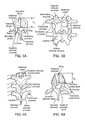
- FIGS. 3A-B show the superior view and posterior view of the lumbar vertebrae.
- V A represents the depth of the lumbar vertebral body in the anterior/posterior or dorsal/ventral direction.
- FIGS. 4A-B show the superior view and posterior view of the thoracic vertebrae.
- V B represents the depth of the thoracic vertebral body in the anterior/posterior or dorsal/ventral direction.
- FIG. 5 is a posterior view of the erector spinae muscle.
- FIG. 6 is a posterior view of the deep layer of the intrinsic back muscles (transversospinal muscles).
- FIG. 7 is a free body diagram illustrating forces acting on a vertebral body during lifting.
- L w represents the effective moment arm around a target vertebral body due to the body weight W and
- L p represents the effective moment arm around a target vertebral body due to the external weight P.
- FIG. 8 is a sagittal view of the spine showing the moment arm of the erector spinae muscles for generating a muscle moment to counteract the forward bending moment.
- L A represents the effective moment arm.
- FIG. 9 is a schematic representation of the instantaneous axis of rotation (IAR) through the vertebral body/intervertebral disc.
- FIG. 10 is a sagittal view depicting the concentration of the compressive load in the anterior region of the spinal column due to the forward bending moment.
- FIGS. 11A-B are sagittal views of the spine depicting the location of the erector spinae muscles before and after placement of an implant according to an exemplary embodiment of the present invention.
- L A represents the moment arm of the erector spinae muscles without the implant and
- L B represents the resulting moment arm after placement of the implant.
- FIG. 12 is a superior view of the cross-section of the lumbar spine illustrating some of the connective tissues and muscles according to embodiments of the present invention.
- FIG. 13 is the posterior view of the spine with a schematically-illustrated implant according to an exemplary embodiment of the present invention.
- FIG. 14 is the sagittal view of the spine with a schematically-illustrated implant according to an exemplary embodiment of the present invention.
- FIG. 15 is the sagittal view of the spine with a schematically-illustrated implant according to an exemplary embodiment of the present invention.
- FIG. 16 is the posterior view of the spine with a schematically-illustrated implant according to an exemplary embodiment of the present invention.
- FIG. 17 is the sagittal view of the spine with a schematically-illustrated implant according to an exemplary embodiment of the present invention.
- FIG. 18 is the posterior view of the spine with a schematically-illustrated implant according to an exemplary embodiment of the present invention.
- FIG. 19 is the posterior view of the spine with a schematically-illustrated implant according to an exemplary embodiment of the present invention.
- FIGS. 20, 21, 24, 25, 28, 28A, 29, 30, 31 and 32 are side views of prostheses according to alternative exemplary embodiments of the present invention.
- FIGS. 22, 23, 26 and 27 are plan views of prostheses according to alternative exemplary embodiments of the present invention.
- FIGS. 33, 34, 35, 36, 37 and 38 are side views of prostheses according to alternative exemplary embodiments of the present invention, wherein bones A, B and C represent cross-sectional views of adjacent vertebrae.
- the spinal column consists of seven cervical vertebrae (C1-C7) in the neck, twelve thoracic vertebrae (T1-T12) in the upper back, five lumbar vertebrae (L1-L5) in the lower back, five bones (that are “fused” together in adults) to form the bony sacrum and three to five bones fused together to form the coccyx or tailbone ( FIG. 1 ).
- Each vertebra consists of a large vertebral body in the front, two strong bony areas called pedicles connected to the vertebral body, and bony posterior structures like the spinous process, the transverse process, etc. The main purpose of these structures is to protect the spinal cord, and to enable the connection of the vertebrae to muscles and ligaments.
- the vertebral body consists of hard exterior shell (cortical bone), with spongy bone (cancellous bone) inside.
- the intervertebral discs are fibrocartilaginous cushions serving as the spine's shock absorbing system.
- Intervertebral discs are composed of an annulus fibrosus and a nucleus pulposus ( FIGS. 2A and 2B ).
- the annulus fibrosus is a strong radial tire-like structure connected to the vertebral end plates.
- the annulus fibrosus encloses the nucleus pulposus.
- Both the annulus fibrosus and nucleus pulposus are composed of water, collagen, and proteoglycans (PGs).
- the nucleus pulposus contains a hydrated gel-like matter that resists compression.
- FSU functional spinal unit
- a FSU consists of two adjacent vertebrae, the intervertebral disc and all adjoining ligaments between them and excludes other connecting tissues such as muscles.
- the two adjacent vertebrae and intervertebral disc also cooperate to form a joint permitting articulation of the spine.
- the spinal column consists of the cervical, thoracic and lumbar segments.
- Each vertebrae of the lumbar segment ( FIGS. 3A and 3B ) comprises the vertebral body, the spinous process and the transverse processes.
- Each vertebral body is attached to a bony arch comprised of two pedicles and two laminae that form a hollow archway (the foramen).
- the vertebral arches are interconnected by paired, fixed facet joints.
- the spinous process protrudes from the junction of the two laminae.
- Transverse processes project from the junction of the pedicles and lamina.
- V A represents the depth of the lumbar vertebral body in the anterior/posterior or dorsal/ventral direction.
- V B represents the depth of the thoracic vertebral body in the anterior/posterior or dorsal/ventral direction.
- V B represents the depth of the cervical vertebral body in the anterior/posterior or dorsal/ventral direction (figure not shown).
- the V A ranges from about 35 mm to about 55 mm
- V B ranges from about 25 mm to about 40 mm
- V C ranges from about 10 mm to about 25 mm.
- the spine has four major muscles—forward flexors (anterior), lateral flexors (lateral), rotators (lateral) and extensors (posterior). See, for example, FIGS. 5, 6 and 12 .
- the deep back muscles (intrinsic back muscles) are grouped into superficial, intermediate, and deep layers depending on their proximity to the surface.
- the superficial layer includes the splenius capitis and cervicis muscles.
- the intermediate back muscles that act as the primary spinal extensors are the erector spinae muscles.
- the erector spinae muscles are on either side of the vertebral column within the posterior and anterior layers of the thoracolumbar fascia.
- the erector spinae muscles straighten a flexed column, and release during its flexion so that the motion is slow and controlled.
- the erector spinae muscles originate at the sacrum and extend through the lumbar, thoracic and cervical spine.
- the erector spinae appears as a single muscle.
- the erector spinae split into three vertical columns ( FIG. 5 ), iliocostalis (lateral), longissimus (intermediate) and spinalis (medial).
- the iliocostalis is named regionally—the iliocostalis lumborum, thoracis and cervicis.
- the longissimus is named regionally—the longissimus thoracis, cervicis and capitis.
- the spinalis is named regionally—the spinalis thoracis, cervicis and capitis.
- the erector spinae muscles are covered by fascia that attach medially to the spinous processes, and laterally to the transverse processes of the cervical and lumbar vertebrae, and to the ribs.
- the deep layer of the intrinsic back muscles are also known as the transversospinal muscle group, and include the semispinalis, multifidus, and rotatores muscles ( FIG. 6 ). These shorter muscles are situated deep to the erector spinae and run obliquely. They originate from the transverse processes of a vertebrae and attach to the spinous processes of a more superior vertebrae.
- the muscles of the semispinalis cross six vertebrae, the multifidus cross four vertebrae, and the rotatores cross one or two vertebrae.
- the interspinalis muscles pass between adjacent spinous processes and the intertransversii muscles pass between adjacent transverse processes.
- Loads on the spine are primarily a result of body weight, muscle activity and externally applied loads.
- the line of gravity of the trunk runs ventral to the axis of the spine, hence, the spine is subjected to a constant forward bending moment.
- This forward bending moment is counteracted by ligament forces and the posterior erector spinae muscles.
- the bending moment on the spine is influenced by the external loads as well as the body posture during lifting ( FIG. 7 ).
- the forward bending moment which includes body weight and any external load, is counteracted by the posterior extensor muscle moment (force times the moment arm of the muscle force).
- the moment arm of the posterior extensor muscle is the distance between the effective line of action of the erector muscle and the instantaneous axis of rotation (IAR) through the vertebral body/intervertebral disc ( FIG. 9 ).
- IAR instantaneous axis of rotation
- FIG. 9 The moment arm of the posterior extensor muscle is the distance between the effective line of action of the erector muscle and the instantaneous axis of rotation (IAR) through the vertebral body/intervertebral disc.
- IAR instantaneous axis of rotation
- Exemplary methods disclosed in this invention comprises selecting at least one of the associated muscle and connective tissues surrounding the vertebrae as target tissue for treatment, and displacing the target tissue without severing the bones or target tissue, thereby redistributing loading within the intervertebral joint to achieve a therapeutic effect.
- the target tissues are displaced posteriorly.
- therapeutic effect means an effect on a treated FSU that reduces or redistributes forces acting on the FSU or target bone structures, in particular the joint formed by the cooperation of the vertebrae and discs, decreases pain or provides another positive outcome for the patient whether across an FSU or in particular parts of an FSU. “Therapeutic effect,” however, does not imply, and should not be understood as requiring, any specific, quantified outcome other than as stated above.
- “Therapeutic location” as used herein refers to a location where a prosthesis or implant is placed in accordance with embodiments of the present invention to achieve a therapeutic effect.
- “therapeutic path” refers to a path of target tissues over the implant or prostheses according to embodiments of the present invention that is displaced from the normal anatomical path of the tissue so as to achieve a therapeutic effect.
- dorsal refers to the back of an organism and ventral to the belly. Cranial refers to the head end and caudal to the tail end. In humans, anterior is used to indicate the ventral surface and posterior is used to indicate the dorsal surface. Superior means toward the head and inferior means toward the feet.
- Proximal refers to the end of a structure nearest a major point of reference and distal refers to the end of a structure furthest from a point of reference. The point of reference is usually the origin of a structure (such as a limb). Proximal and distal are relative terms. Medial means nearer the midline of the body and lateral means further from the midline of the body.
- Superficial refers to structures nearer the skin, and deep to structures further away from the skin.
- a sagittal plane divides the body into right and left (or medial and lateral) parts.
- a frontal (or coronal) plane passes from right to left and divides the body into dorsal and ventral (or posterior and anterior) parts.
- a transverse plane passes perpendicular to the long axis of the body and divides the body into cranial and caudal (head and tail) portions.
- Exemplary embodiments of the invention described herein are particularly directed to treatment of the human spine.
- specific features described in connection with one exemplary embodiment may be incorporated in other exemplary embodiments unless otherwise noted.
- the exemplary embodiments described are thus included to illustrate features of the invention, not limit it.
- FIGS. 11A and 11B illustrate an exemplary embodiment of the present invention with a schematically-illustrated implant according to one embodiment positioned along the posterior of the vertebral body to assist in redistributing the forces acting on vertebral body/intervertebral disc to provide a therapeutic effect.
- an implant placed adjacent to the vertebral body forces the target tissues that run there along to assume a more posterior path. That longer path may have a number of beneficial effects, including increasing the moment arm of the target tissue.
- the effective posterior moment is increased to more effectively counter the forward bending moment. This moves the IAR dorsally (or posteriorly), away from the anterior of the vertebral body/intervertebral disc.
- posterior displacements of between about 10 mm to about 50 mm may be preferred, more preferably in the range of about 15 mm to about 45 mm, most preferably in the range of about 20 mm to about 40 mm.
- the implants of the present invention move the IAR measured during flexion by more than 3 mm dorsally, more preferably by more than 6 mm dorsally, most preferably by more than 9 mm dorsally.
- the relationship between the dorsal displacement of the IAR and the therapeutic effect will depend on the multiple factors including the size of the vertebral body (e.g.; V A , V B and V C ), the location of the vertebral body (cervical, thoracic or lumbar), the state of the adjacent intervertebral discs, the state of the adjacent intervertebral bodies, the location of the IAR prior to treatment etc.
- the location of the prosthesis may be at the same spinal level as the one being treated or could be located at a spinal level more cranial or caudal to the one being treated.
- the prosthesis may also span multiple spinal vertebrae.
- an implant is placed on either side of the spinal process.
- the implant acts as a spacer to displace the tissue posterior to the spine.
- the erector spinae muscles are displaced posteriorly.
- the redistribution of the force could alleviate pain associated with degenerative disc disease and could slow down or halt the degeneration of the disc.
- osteoporotic vertebrae by redistributing the forces and reducing the compressive load on the anterior region of the vertebral body, the risk of compression fracture of the vertebral body may be decreased.
- the implant may be attached to the vertebral body, the articular process, the transverse process, the spinous process, the lamina, the facet, the pedicle or any other bony structure of the vertebrae using screws, hooks, bands, sutures, wires, etc.
- the implants may be attached to the vertebral body at a single location or at multiple locations. The implants may be attached only in the cranial region or only in the caudal region.
- the implant may be attached to bone located medial to the implant or lateral to the implant. In other embodiments, the implant may be attached to bone ventral to the implant or dorsal to the implant. Implants may be attached to a vertebral body located away from the vertebral body/segment being treated.
- Implants may have sections or features for tissue displacement (displacement portion or segment), sections or features for fixation (fixation portion or segment), and a spanning portion that connects the displacement portion and the fixation portion.
- the displacement segment, the spanning segment and the fixation segment may be in alignment with each other or may be displaced from each other.
- the displacements or offset between the segments may be cranial, caudal, lateral, medial, ventral, dorsal, oblique etc.
- Implants may be rigid or substantially rigid or soft compliant prostheses secured to adjacent bone or the surrounding tissues.
- such implants may be rigid, semi-rigid or soft compliant prostheses secured to adjacent bone or the surrounding tissues.
- Rigid or substantially rigid prostheses according to embodiments of the invention described herein could be made of known bone-compatible implant materials such as titanium or stainless steel. Biocompatible polymers, ceramics, and other materials may also be used.
- the bearing surface of the prostheses should be designed to minimize negative effects of movement of the connective tissues across the implant surface, having a low coefficient of friction with no or minimal rough edges, corners, or discontinuities.
- Such prostheses could be implanted arthroscopically or using a mini-open or open surgical approach.
- Implants also may be held in place by the surrounding tissues without using a fixation element.
- Soft compliant prostheses could be filled with water, saline, silicone, hydrogels, etc., sufficient to move the tissue laterally (relative to the direction of force exerted by such tissue) as described above. Such a soft compliant prosthesis could be placed in a deflated state and then inflated to the appropriate thickness.
- implants may be filled with other flowable materials including beads or other particles made of metal, polymer, or foam material, optionally in a liquid medium, which conform to the adjacent bone or tissue surfaces.
- the implant could be inflated with a curable material, such as a polymer, which is substantially liquid for a period of time during the implantation procedure, but then cures into a harder permanent state.
- a curable material such as a polymer
- Thixotropic materials such as hydrogels derived from hyaluronic acid, change their mechanical properties as shear stress is applied to them.
- An implant filled with such materials could be made to change the amount of displacement that it provides based on the shear stress that it sees from overlying target tissues during flexion/extension.
- Implants may be coated with materials to reduce friction such as hydrophilic coatings or polytetrafluoroethylene (PTFE) coatings.
- the prosthesis may be adjustable to allow the dimensions such as thickness of the prosthesis to be adjusted during surgery or any time after surgery.
- Rigid or substantially rigid prostheses could be made of known bone-compatible implant materials such as titanium or stainless steel. Biocompatible polymers, ceramics, and other materials may also be used. Coatings like titanium nitride, titanium niobium nitride etc. may be used to increase wear resistance, lubricity etc. Whether rigid or compliant, the surface of the prosthesis should be designed to minimize negative effects of movement of the connective tissues across the implant surface. Such prosthesis could be implanted arthroscopically or using a mini-open or open surgical approach.
- the displacement portion and the fixation portion of prostheses according to the invention may be of unibody construction, or may be formed of two or more parts depending on desired function.
- the fixation portion may be stainless steel or titanium textured to enhance bony ingrowth and solid screw fixation
- the bearing/displacement portion could be made of a different material, for example, pyrolytic carbon to enhance the ability of overlying tissues to slide across the implant, or PTFE, silicone or other low-friction polymer with suitable wear characteristics to provide a softer bearing surface.
- the displacement portion could be comprised of a substrate of one material with an overlying layer forming the bearing material. The substrate could be either attached to or contiguous with the fixation portion.
- the fixation portion of the implant may have a relief feature to minimize contact with the underlying bone, thereby minimizing disruption of the periosteal layer.
- the bearing surface may be hard and smooth, made from materials such as polished pyrolytic carbon, steel, or titanium, or coated or covered with a lubricious material, such as PTFE. It might alternatively be designed to encourage adhesion and ingrowth of the connective tissue onto this surface.
- the surface may be porous, roughened, or configured with openings into which bone or scar tissue may grow to enhance adhesion.
- the implant could have a shape or feature adapted to guide the muscles and tendons and retain their position on the implant.
- a groove or trough could be provided on the outer surface of the prosthesis through which the muscles and tendons would extend. These muscles and/or tendons are aligned with the groove when the implant is installed.
- the implant could include a ring or eyelet with a discontinuity to allow placement of the ring or eyelet around the muscles/tendons. Implants may have also varying thickness so as to provide varying displacement of the muscles and tendons.
- the implant could be anchored to the underlying bone with suitable fasteners such as screws.
- suitable fasteners such as screws.
- unicortical screws, bicortical screws, cancellous screws, cannulated screws, polyaxial screws, screws that lock into the implant etc. may be used.
- the screw holes may be locking threads or other locking features.
- the screw holes may be oriented in different directions to improve the stability of the anchored implant.
- different types of screws may be used in different regions of the implant.
- implants may also be placed without securing it to surrounding tissues, for example without placement of bone-penetrating screws.
- the device may be held in place solely by its position between the vertebral body and the vertebral muscles.
- the device may be contoured to fit in between certain spinal processes, with certain features to prevent it from sliding superiorly or inferiorly. It could also be held in that location by the muscles on top of it.
- Soft compliant prostheses could be filled with water, saline, silicone, hydrogels etc. sufficient to displace tissue as described above. Such a soft compliant prosthesis could be placed in a deflated state and then inflated to the appropriate thickness. Additionally or alternatively, the thickness of the prosthesis may be adjusted during surgery or at any time after surgery.
- Rigid or substantially rigid prostheses could be made of known bone compatible implant materials such as titanium or stainless steel.
- Implants on either side of the spinous process may be identical or different. Implants on either side of the spinous process may be independent (without any connecting segment) or could be connected with a connecting section.
- the connecting segment may be rigid, substantially rigid or flexible. Such asymmetric implants may be useful in treating scoliosis or spines with mild lateral bending.
- extension, rotation, and lateral bending are not affected. In other embodiments, extension, rotation and lateral bending may be minimally affected.
- the methods and devices of the present invention may be used to treat a variety of spinal disorders. For example, for treatment of spinal sagittal plane instability resulting from degenerative spondylolisthesis or surgical decompression or laminectomy. In some embodiments, the treatment could be directed towards instability due to ligament laxity. Alternatively, the methods and devices may be used to alleviate pain related to forward bending in patients with degenerative disc disease (DDD). In some embodiments, pain associated with extension, rotation and lateral bending may be alleviated.
- DDD degenerative disc disease
- the methods and devices of the present invention may result in reduced segmental motion during flexion and increased spinal stability during flexion.
- the methods and devices may increase flexion stiffness.
- the methods and devices may increase facet engagement.
- the devices and methods of the present invention do not bear or transmit axial compressive loads on the spine.
- the methods and devices of the present invention could be compatible with decompression for patients suffering from lumbar spinal stenosis, for example, laminotomy, facetectomy or foraminotomy.
- the devices could also be used in conjunction with spinous process sparing surgeries and in surgeries where the part or all of the spinous process is removed.
- the implants of the present invention may be considered to be permanent implants that remain in the patient for many years or implants that are used temporarily for short duration of a few months for temporary pain reduction or to enable recovery from an adjunct spinal surgery.
- the devices of the present invention may be used as a permanent or temporary implant in conjunction with vertebroplasty or kyphoplasty to stabilize the spinal segment that underwent vertebroplasty or kyphoplasty.
- the devices may be used to stabilize adjacent spinal segments to minimize the incidence of adjacent segment disease (e.g.; vertebral fracture, disc degeneration etc.) after vertebroplasty or kyphoplasty.
- the devices may be used to address sagittal or translation instability in spinal segments adjacent to segments that have undergone fusion surgery or segments that are stiff.
- Implants of the present invention may take many forms as discussed in more detail below with respect to various exemplary embodiments of the present invention.
- FIGS. 13-19 schematically depict the general size, shape, and location on the spine of implants according to exemplary embodiments of the present invention.
- implants also may be placed on either or both sides of the spinous process.
- Implant 101 schematically shown in FIGS. 13-14 , is located posterior to the vertebral body in a region generally as shown, which may be in contact with the lamina (L), displacing the posterior muscles.
- Implants in embodiments of the present invention may span about the height of a vertebral body, the height of the lamina (L), or the gap (G) between two transverse processes, or may extend cranially and/or caudally beyond the adjacent transverse processes as in implants 103 and 105 shown in FIGS. 15 and 16 .
- the lateral width of the implant may cover about the width of the lateral gutter or part of the lateral gutter.
- the implant may be placed medially in contact with the spinous processes or more laterally in contact with the articular processes or in contact with both the processes or with no contact to either process.
- Different regions of the implant may have different surface features, cross-sectional shapes, surface textures etc. Additionally, different regions of the implant may have different heights or thicknesses.
- region 121 and 122 which are in contact with the underlying lamina may have thickness greater than regions 123 and 124 .
- regions 123 and 124 may be thicker.
- the implant may have extensions ( 127 , 126 and 125 ) that reside in the notches between the vertebral bodies thereby providing resistance to implant displacement during flexion/extension.
- FIG. 18 depicts a schematically-illustrated embodiment of the invention, wherein implant 109 extends laterally outside the articular process and displaces tissue posterior to the transverse processes.
- Two displacement segments 150 and 155 may be connected with a connecting segment 151 .
- Segment 151 may be flexible or rigid. The height of the connecting segment 151 may be such that it is in contact with the articular process of the superior and inferior vertebrae or alternatively, it may be narrow such that it does not contact the articular processes and does not interfere with any spinal motion.
- Displacement segment 155 may also have regions with different surface features, cross-sectional shapes, surface textures, thicknesses etc. For example, regions 152 and 153 in contact with the transverse process may be thicker compared to the rest of displacement segment 155 .
- FIG. 19 schematically depicts a further embodiment in which implant 111 extends bilaterally on either side of the spinous process.
- Two displacement segments 160 and 161 are connected with a connecting segment 165 .
- Segment 165 may be flexible or rigid.
- the height of the connecting segment 165 may be such that it is in contact with the spinous process of the superior and inferior vertebrae or alternatively, it may be narrow such that it does not contact the spinous processes and does interfere with any spinal motion.
- FIGS. 26 and 27 Further alternative embodiments are shown in FIGS. 26 and 27 .
- implant 113 has displacement sections 241 and 240 with different dimensions 243 and 242 joined by connecting segment 245 as shown to accommodate various anatomic variations as may be encountered in different patients.
- implant 115 shown in FIG. 27 includes displacement sections 250 and 251 of the same dimensions 252 and 253 joined by connecting segment 255 .
- devices of the present invention may be placed under the multifidus muscles, in contact with the posterior surface of the vertebral body structures. In other embodiments, devices of the present invention may be placed above the multifidus muscles, in contact with the erector spinae muscles.
- FIG. 20 (implant 200 ) and 21 (implant 201 ) show further exemplary embodiments of devices of the present invention.
- the thickness of the implant may vary along the length of the implant, in the cranial/caudal direction.
- regions 205 and 203 (T 1 and T 2 ) may be thicker or wider than region 204 (T 3 ) thereby displacing the target soft tissue more in certain locations around the target vertebral body than in other locations.
- the end regions 211 and 213 (T x and T z ) may be thinner or narrower than middle region 212 (T y ) of implant 220 .
- implant 201 may have a lumen 231 to enable guiding the implant percutaneously to the target location.
- the implant may be inserted and guided in a deflated state. Once the implant position is confirmed (for example, with radiographic markers on the implant), the implant may be inflated to achieve the appropriate tissue displacement.
- the implant may be filled with a liquid or gas under suitable pressure to allow displacement of the target tissue.
- the implant may have one or more hollow chambers defined by an outer wall (e.g. at 232 in FIG.
- an inflation port for introduction of inflation fluid by means of an inflation device, which may be a syringe, pump, or a device similar to the inflation devices used for inflation of angioplasty balloons as will be understood by persons of ordinary skill in the art.
- an inflation device which may be a syringe, pump, or a device similar to the inflation devices used for inflation of angioplasty balloons as will be understood by persons of ordinary skill in the art.
- an implant 260 may have separate chambers 261 , 262 and 263 ( FIG. 28 ). These separate chambers will allow the placement of a single implant to distract soft tissue from multiple vertebrae, while still permitting appropriate bending motion of the spine.
- flexible, extensible, compressible tubular sections 264 are provided between each chamber 261 , 262 , 263 . The tubular sections between the chambers may facilitate positioning by allowing each chamber to remain in a fixed position relative to its associated vertebrae during flexion, extension, and sideways bending of the spine.
- Implant 260 may be temporarily inflated with air, saline, or other medium allowing appropriate visualization with the imaging modality being used.
- the temporary inflation medium can be removed and replaced with a permanent inflation material such as a curable polymer or hardening cement, two-part epoxy, or other suitable material.
- a permanent inflation material such as a curable polymer or hardening cement, two-part epoxy, or other suitable material.
- the tubular sections 264 may be provided with inflation lumens communicating with each chamber from a proximal end, and a lumen to hold a semi-rigid pusher or stiffening wire to help advance the implant into position.
- the implant may be anchored to a single vertebral body.
- the implant may be attached using screws, anchors, hooks, wires etc.
- the implant may have one or more features for coupling to an anchoring device, such as a loop, hole, or channel.
- implant 270 FIG. 29
- Enlarged portion 272 may be configured and dimensioned to be received in a depression between adjacent vertebrae or otherwise specially configured to match a corresponding space in in the patient anatomy.
- Inferior end 273 may be unattached after implantation.
- multiple screws may be used to anchor the implant to a single vertebral body, such as through holes 281 , 282 near opposing ends of implant 280 ( FIG. 30 ).
- the screws could be placed in through the pedicle, the lamina or any other bony region of the vertebrae.
- the implant may be anchored using a hook, for example implant 290 ( FIG. 31 ) may be anchored using one hook 291 near its superior end 292 .
- the hook may be configured to anchor to the articular process, the transverse process, the spinous process, the lamina, the pedicle or any other bony structure of the vertebrae.
- inferior end 293 is not provided with an attachment means.
- multiple hooks may be used to anchor the implant to a single vertebral body.
- a combination of anchoring elements may be utilized on the same vertebral body.
- enlarged portions 283 or 294 may be configured and dimensioned to match a corresponding profile in the patient anatomy.
- multiple anchoring elements may be used to anchor the implant to multiple vertebrae ( FIG. 32 ).
- Hooks 401 , 402 may be coupled to the implant 400 at the opposing superior and inferior ends, respectively.
- An enlarged portions 403 also may be provided in this embodiment.
- Implants described herein in accordance with various embodiments of the invention may be used with cervical, thoracic or lumbar vertebrae. Implants may be placed at one level or at multiple levels of the spine. Implants may span a single level or multiple levels of the spine.
- implants 300 , 310 , 420 , 410 , 405 , 430 , 440 , and 450 are shown, respectively, in FIGS. 22, 23, 33-38 .
- the implants may be substantially rigid.
- the implants may have three regions, a fixation region for attaching the implant to surrounding tissue, a displacement region that displaces the target tissue and a spanning section that interconnects the fixation and displacement regions.
- Implant fixation portions 312 ( FIG. 23 ), 301 ( FIG. 22 ), 421 ( FIG. 33 ), 411 ( FIG. 34 ), 408 ( FIG. 35 ), 431 ( FIG. 36 ), 441 ( FIG. 37 ) and 451 ( FIG. 38 ) may be configured to be anchored to the underlying bone using screws (S) placed through bone screw holes 303 , 311 , 422 , 412 , 409 , 432 , 442 , and 452 , respectively.
- thickness of fixation portion of the implant may vary.
- the thickness of the fixation portion of the implant may be uniform or may vary.
- Regions of the fixation portion under higher mechanical load may be thicker than regions under lower mechanical loads.
- the thickness of the fixation region may also be selected to ensure that the screw-heads used to fix the implant do not protrude over the surface of the implant so as to protect adjacent tissues from injury.
- Spanning sections 314 ( FIG. 23 ), 423 ( FIG. 33 ), 413 ( FIG. 34 ), 407 ( FIG. 35 ), 433 / 435 ( FIG. 36 ), 443 ( FIG. 37 ) and 453 ( FIG. 38 ) may have thickness similar to that of the fixation portion.
- Bone A, Bone B and Bone C in the figures schematically represent cross-sectional views of adjacent vertebrae. Persons of ordinary skill in the art will appreciate that a principal consideration for the spanning section is sufficient structural integrity to maintain the displacement portion of the desired treatment position. In the displacement portion, displacement distance and thickness may be considered separately.
- Displacement distance is the distance by which the bearing surface of the displacement portion extends beyond the natural anatomical track of the target tissue, in other words, the magnitude of displacement of tissue created by the implant.
- the thickness of the displacement portion may or may not be related to the displacement distance.
- the thickness of the displacement portion ( 424 , 414 , 406 , 434 / 436 , 444 / 445 and 454 , respectively) may be substantially less than the overall displacement distance D.
- the displacement portion may be elevated off the underlying bony surface of the vertebrae and may be preferred to minimize any disruption of the periosteal layer.
- the thickness of the displacement portion and the tissue displacement may be identical, whereby the displacement portion of the implant is in contact with the underlying bone, as, for example, shown in FIG. 37 with displacement portion 445 .
- displacement distance across the displacement portion may vary.
- the displacement portion may be in contact with the underlying tissue and the target soft tissue is displaced by a distance equivalent to the thickness of the displacement portion; thus displacement distance would equal thickness in such an embodiment.
- the displacement portion may be elevated above the underlying tissue and the target soft tissue is displaced by a distance greater than the thickness of the displacement region; thus displacement distance is greater than thickness.
- the implant may have two or more spanning sections 433 and 435 ( FIG. 36 ) connecting a fixation section 431 to a plurality of displacement portions 434 , 436 .
- the tissue displacements D 1 and D 2 of the displacement portions may be the same or different.
- implant 440 FIG. 37
- implant 440 includes one displacement portion 444 spaced from the underlying bone and second displacement portion 445 on the underlying bone.
- the displacement of the connective tissue could be adjusted by adjusting the device pre-operatively, intra-operatively or post-operatively.
- the spanning sections may also comprise adjustable mechanisms (e.g. a pin, jack, screw, inflatable member, hydraulic piston, or hinge) to movably or pivotably alter the orientation or angle between the fixation section and the displacement section (for example, 453 in FIG. 38 ) to achieve the appropriate level of tissue displacement,
- the adjustment mechanisms themselves may be radiopaque and/or otherwise discernible from the rest of the implant under x-ray in order to enable post-surgical percutaneous adjustment of the device.
- target features can be built into the device to locate the adjustment points without having the screws or adjustment means themselves radiopaque, such as radiopaque rings or markers built into the bearing surface of the device itself.
- Devices may include electric, pneumatic, or hydraulic motors or actuators to alter the displacement that may be remotely controlled, including by mechanisms that enable wireless communication to alter the displacement after implantation.
- the displacement may be adjusted by applying an energy field (e.g.; magnetic field, electric field, thermal field etc.) transdermally from an external location.
- an energy field e.g.; magnetic field, electric field, thermal field etc.
- the fixation portion may be cranial to the displacement portion (e.g.; FIGS. 33, 34 and 38 ). In other embodiments, the fixation portion may be caudal to the displacement portion (e.g.; FIG. 35 ). In other embodiments, there may be displacement section cranial and caudal to the fixation portion (e.g.; FIGS. 36 and 37 ). In other embodiments, the fixation portion may extend cranially or caudally from the location of the anchoring element 1 (e.g.; FIG. 37 ). In yet other embodiments the displacement section may be offset laterally relative to the fixation portion ( FIG. 23 ).
- implants of the present invention may be anchored to the target vertebral body.
- the target intervertebral disc may be cranial to the vertebral body to which the implant is anchored.
- the target intervertebral disc may be caudal to the vertebral body to which the implant is anchored.
- the implants of the present invention may be anchored cranial or caudal to the target vertebral body.
- the target vertebral body may be one spinal level caudal or one spinal level cranial to the vertebral body used to anchor or fix the implant.
- the target vertebral body may be two or more spinal levels caudal or two or more spinal levels cranial to the vertebral body used to anchor or fix the implant.
- fixation portion, the spanning portion and/or the displacement portion, or portions thereof may be aligned, i.e. stacked on top of each other or overlapping in the ventral-dorsal direction (e.g. implant 300 in FIG. 22 ).
- the implant may be anchored to a single vertebral body.
- the implant may be attached using screws, anchors, wires etc.
- implant 300 FIG. 22
- implant 310 FIG. 23
- a bone-facing implant surface 302 could be concave to make good contact with the underlying bone of the vertebral body.
- the bone-facing surface may include spikes, ridges, bumps, barbs, or other textural features to enhance the anchoring of the implant.
- the bone-facing surface may also be coated with an ingrowth promoting agent or may inherently have a porous structure to enable bone ingrowth.
- the posterior surface of the implant 304 which is in contact with soft tissue (multifidus muscles, erector spinae muscles etc.) may be smooth, low-friction, and free of sharp edges or protrusions to avoid tissue injury, and may be contoured to be concave or otherwise shaped to ease the motion of the muscle during flexion/extension of the spine.
- the radius of curvature of the concave surfaces on the anterior and posterior sides of the implant may be identical or different.
- the radius of curvature of each surface may also vary along the length of the implant, in the cranial/caudal direction.
- the thickness of implant 300 , T A in FIG. 22 could be constant or variable in the cranial/caudal and medial/lateral directions.
- the thickness of displacement portion 313 and fixation portion 312 could be identical or different.
- the thickness of the connecting segment 314 could constant or variable to bridge the difference in thicknesses of the two segments.
- the lateral distance between sections 312 and 31 (W A ) also may be varied.
- the connecting segment 314 may also be a spanning section, connecting the displacement portion 313 with the fixation portion 312 .
- the displacement portion 313 may also have a secondary fixation region, including a screw hole or other means for anchoring the displacement region 313 to bone.
- the lengths of each segment 315 (L B ) and 316 (L C ) could be identical or different.
- L B could be greater than L C . In other embodiments, L C could be greater than L B . In some embodiments, L B and L C may span the height of one vertebral body. In other embodiments, L B and L C may span more than one vertebral body.
- the anterior surface of the implant may also be contoured in the medial/lateral direction to conform to the contours of the posterior surface of the vertebral body.
- the implant may have features to enable it to be attached to the surrounding soft tissue, thereby preventing any dislocation of the implant.
- the prosthesis may have an attached suture that can be wrapped around the target soft tissue.
- the surface of the implant could be modified as needed for interaction with the soft/hard tissue.
- the surface could be smooth to allow for easy movement of the soft tissue across the surface.
- the surface may have an adhesive surface to allow attachment to underlying bone or soft tissue.
- the surface could be coated with a hydrophilic or hydrophobic layer.
- the surface may have a polymeric coating for drug release. Drugs like anti-inflammatory drugs and antibiotics could be incorporated into the polymeric coating.
- the implant may have design features which accommodate the relative motion of the vertebrae.
- the implant since the posterior aspects of the vertebrae become closer and more distant as the spine is flexed and straightened, it may be advantageous to have an implant with vertebral sections which hold their position relative to each vertebra, either by fixation, adhesion, shape, or other means, such as having features which interact with the spinous processes on each vertebrae.
- This implant could further have intervertebral sections which flex, extend, and compress freely with the motion of the spine. This will prevent longitudinal motion of the implant surface relative to the vertebral bodies.
- These vertebral and intervertebral sections might not be dramatically different or segregated.
- the implant might be cast from a relatively flexible, compressible material, with harder elements in the center of this flexible material corresponding to the locations of the vertebrae.
- An implant which spans several vertebral bodies may be inserted from one end of the desired implanted location. It would be desirable for vertebral sections of the implant to naturally tend to lock into position relative to each vertebrae and hold that position, so that additional incisions to insert fixation elements are not necessary.
Abstract
Description
Claims (5)
Priority Applications (2)
| Application Number | Priority Date | Filing Date | Title |
|---|---|---|---|
| US13/974,930 US9468466B1 (en) | 2012-08-24 | 2013-08-23 | Method and apparatus for altering biomechanics of the spine |
| US15/295,560 US10898237B2 (en) | 2012-08-24 | 2016-10-17 | Method and apparatus for altering biomechanics of the spine |
Applications Claiming Priority (3)
| Application Number | Priority Date | Filing Date | Title |
|---|---|---|---|
| US201261693140P | 2012-08-24 | 2012-08-24 | |
| US201361792720P | 2013-03-15 | 2013-03-15 | |
| US13/974,930 US9468466B1 (en) | 2012-08-24 | 2013-08-23 | Method and apparatus for altering biomechanics of the spine |
Related Child Applications (1)
| Application Number | Title | Priority Date | Filing Date |
|---|---|---|---|
| US15/295,560 Continuation US10898237B2 (en) | 2012-08-24 | 2016-10-17 | Method and apparatus for altering biomechanics of the spine |
Publications (1)
| Publication Number | Publication Date |
|---|---|
| US9468466B1 true US9468466B1 (en) | 2016-10-18 |
Family
ID=57120786
Family Applications (2)
| Application Number | Title | Priority Date | Filing Date |
|---|---|---|---|
| US13/974,930 Active 2034-05-11 US9468466B1 (en) | 2012-08-24 | 2013-08-23 | Method and apparatus for altering biomechanics of the spine |
| US15/295,560 Active 2034-06-16 US10898237B2 (en) | 2012-08-24 | 2016-10-17 | Method and apparatus for altering biomechanics of the spine |
Family Applications After (1)
| Application Number | Title | Priority Date | Filing Date |
|---|---|---|---|
| US15/295,560 Active 2034-06-16 US10898237B2 (en) | 2012-08-24 | 2016-10-17 | Method and apparatus for altering biomechanics of the spine |
Country Status (1)
| Country | Link |
|---|---|
| US (2) | US9468466B1 (en) |
Cited By (4)
| Publication number | Priority date | Publication date | Assignee | Title |
|---|---|---|---|---|
| CN110217313A (en) * | 2019-06-27 | 2019-09-10 | 上海大学 | The bionical body of stiffness variable of one species muscle fibre driving |
| US10828168B2 (en) | 2017-05-10 | 2020-11-10 | Howmedica Osteonics Corp. | Patient specific composite knee replacement |
| US11065037B2 (en) * | 2016-05-19 | 2021-07-20 | Auctus Surgical, Inc. | Spinal curvature modulation systems and methods |
| US11298241B2 (en) * | 2007-03-29 | 2022-04-12 | Life Spine, Inc. | Radially expandable spinal interbody device and implantation tool |
Families Citing this family (3)
| Publication number | Priority date | Publication date | Assignee | Title |
|---|---|---|---|---|
| US9439685B2 (en) * | 2009-05-12 | 2016-09-13 | Bullard Spine, Llc | Multi-layer osteoinductive, osteogenic, and osteoconductive carrier |
| US11452589B2 (en) | 2018-01-03 | 2022-09-27 | Allevetix Medical Ltd. | Implantable anchoring device and methods of use |
| US10368976B2 (en) * | 2018-01-03 | 2019-08-06 | Allium Medical Solutions Ltd. | Implantable anchoring device and methods of use |
Citations (508)
| Publication number | Priority date | Publication date | Assignee | Title |
|---|---|---|---|---|
| US2632440A (en) | 1947-12-17 | 1953-03-24 | John M Hauser | Leg brace joint and lock |
| US2877033A (en) | 1956-03-16 | 1959-03-10 | Dreher Mfg Company | Artificial joint |
| US3242922A (en) | 1963-06-25 | 1966-03-29 | Charles B Thomas | Internal spinal fixation means |
| US3648294A (en) | 1969-02-08 | 1972-03-14 | Esfandiar Shahrestani | Endoprostheses, especially for hip joints |
| US3681786A (en) | 1970-07-13 | 1972-08-08 | Medical Eng Corp | Solid human prosthesis of varying consistency |
| US3779654A (en) | 1971-08-06 | 1973-12-18 | R Horne | Artificial joint |
| US3872519A (en) | 1974-04-04 | 1975-03-25 | Nicholas J Giannestras | Total ankle prosthesis |
| US3875594A (en) | 1973-08-27 | 1975-04-08 | Dow Corning | Surgically implantable prosthetic joint having load distributing flexible hinge |
| US3879767A (en) | 1972-01-26 | 1975-04-29 | Cutter Lab | Prosthesis for articulating body structures |
| US3886599A (en) | 1974-07-25 | 1975-06-03 | Schlein Louis Charles | Surgically implantable total ankle prosthesis |
| US3889300A (en) | 1974-08-28 | 1975-06-17 | Wright Mfg | Articulated two-part prosthesis replacing the ankle joint |
| US3902482A (en) | 1974-05-21 | 1975-09-02 | George A Taylor | Mechanical joint for an orthopedic brace or prosthesis |
| US3964106A (en) | 1975-03-03 | 1976-06-22 | Physical Systems, Inc. | Three-part total knee prosthesis |
| US3988783A (en) | 1976-01-21 | 1976-11-02 | Richards Manufacturing Company, Inc. | Prosthetic collateral ligament |
| US4007495A (en) | 1976-05-28 | 1977-02-15 | Frazier Calvin H | Patello-femoral prothesis |
| US4041550A (en) | 1976-07-30 | 1977-08-16 | Frazier Calvin H | Artificial patella and method of repairing a natural patella |
| US4052753A (en) | 1976-08-02 | 1977-10-11 | Dedo Richard G | Knee spacer and method of reforming sliding body surfaces |
| US4054955A (en) | 1976-01-29 | 1977-10-25 | Arnold Ivanovich Seppo | Orthopaedic endoapparatus designed to grow a new live shoulder and hip joint, to reconstruct a deformed joint or to restore a pathologically dysplastic and congenitally luxated joint |
| SU578063A1 (en) | 1971-05-20 | 1977-10-30 | Seppo Arnold | Orthopedic endoapparatus for restoring hip joint |
| SU578957A1 (en) | 1976-03-30 | 1977-11-05 | Pozdnikin Yurij | Method of reconstruction of cotyloid cavity at dysplasia of hip joint |
| US4069518A (en) | 1976-08-31 | 1978-01-24 | Groth Jr Harry E | Total ankle prosthesis |
| SU624613A1 (en) | 1977-05-10 | 1978-09-25 | Tikhonenkov Egor S | Method of treating congenital femur dislocation |
| SU640740A1 (en) | 1977-07-12 | 1979-01-05 | Предприятие П/Я В-2769 | Arrangement for developing mobility of the joint of lower extremities |
| US4156944A (en) | 1976-11-15 | 1979-06-05 | Sulzer Brothers Limited | Total ankle prosthesis |
| US4158894A (en) | 1978-03-13 | 1979-06-26 | Worrell Richard V | Patellar prosthesis and method of implanting the same |
| US4164793A (en) | 1978-04-26 | 1979-08-21 | Swanson Alfred B | Lunate implant |
| SU704605A1 (en) | 1978-03-14 | 1979-12-25 | Е. С. Тихоненков и С. . И. Федоров | Method of fixing fragments of the femur after intertrochanteric and supratrochateric osteotomy |
| US4187841A (en) | 1978-07-07 | 1980-02-12 | Knutson Richard A | Bone compression or distraction device |
| SU719612A1 (en) | 1977-10-28 | 1980-03-05 | Tikhonenkov Egor S | Method of recessing cotyloid cavity |
| SU741872A1 (en) | 1978-05-04 | 1980-06-25 | за вители | Splint for treating femur congenital dislocation |
| US4246660A (en) | 1978-12-26 | 1981-01-27 | Queen's University At Kingston | Artificial ligament |
| US4285070A (en) | 1978-06-05 | 1981-08-25 | Minnesota Mining And Manufacturing Company | Prosthetic device |
| US4308863A (en) | 1979-10-18 | 1982-01-05 | Ace Orthopedic Manufacturing, Inc. | External fixation device |
| US4353361A (en) | 1980-08-25 | 1982-10-12 | Foster Robert W | Orthotic/prosthetic joint |
| US4367562A (en) | 1980-06-19 | 1983-01-11 | Georges Gauthier | Joint prosthesis |
| JPS59131348U (en) | 1983-02-23 | 1984-09-03 | 日産自動車株式会社 | Automotive wiper circuit |
| US4470158A (en) | 1978-03-10 | 1984-09-11 | Biomedical Engineering Corp. | Joint endoprosthesis |
| US4501266A (en) | 1983-03-04 | 1985-02-26 | Biomet, Inc. | Knee distraction device |
| SU1186204A1 (en) | 1984-05-28 | 1985-10-23 | Московский Ордена Ленина И Ордена Октябрьской Революции Авиационный Институт Им.Серго Орджоникидзе | Apparatus for surgical treatment of hip joint injures |
| US4570625A (en) | 1981-08-06 | 1986-02-18 | National Research Development Corporation | Apparatus for external fixation of bone fractures |
| US4576158A (en) | 1983-01-28 | 1986-03-18 | Region Wallone | Method for determining the stability of an orthopedic device composed of an external fixation bar during setting of bone fractures |
| CA1205602A (en) | 1982-09-10 | 1986-06-10 | William C. Bruchman | Prosthesis for tensile load-carrying tissue |
| SU1251889A1 (en) | 1984-01-27 | 1986-08-23 | Ленинградский Ордена Трудового Красного Знамени Научно-Исследовательский Детский Ортопедический Институт Им.Г.И.Турнера | Apparatus for dynamic unloading of hip joint |
| US4621627A (en) | 1984-12-18 | 1986-11-11 | Orthofix S.R.L. | External axial fixation device |
| US4637382A (en) | 1982-04-27 | 1987-01-20 | Brigham & Women's Hospital | Motion-guiding load-bearing external linkage for the knee |
| US4642122A (en) | 1986-04-02 | 1987-02-10 | Laure Prosthetics, Inc. | Toe implant |
| SU1316666A1 (en) | 1984-09-27 | 1987-06-15 | В. В. Василенкайтис | Arrangement for relieving the load of a joint |
| US4696293A (en) | 1982-09-30 | 1987-09-29 | Ciullo Jerome V | Hinged external fixator |
| US4759765A (en) | 1986-03-17 | 1988-07-26 | Minnesota Mining And Manufacturing Company | Tissue augmentation device |
| US4759766A (en) | 1984-09-04 | 1988-07-26 | Humboldt-Universitaet Zu Berlin | Intervertebral disc endoprosthesis |
| US4776851A (en) | 1986-07-23 | 1988-10-11 | Bruchman William C | Mechanical ligament |
| US4846842A (en) | 1987-06-25 | 1989-07-11 | Connolly & Mcmaster | Body joint rotation support device |
| US4863471A (en) | 1987-01-07 | 1989-09-05 | Sulzer Brothers Limited | Crucial ligament replacement for a knee joint |
| US4871367A (en) | 1987-09-03 | 1989-10-03 | Sutter Biomedical Corporation | Surgically implanted prosthesis |
| US4873967A (en) | 1987-04-27 | 1989-10-17 | Sutherland Jeffrey L | Knee orthosis |
| US4883486A (en) | 1988-05-31 | 1989-11-28 | Indu Kapadia | Prosthetic ligament |
| US4904261A (en) | 1987-08-06 | 1990-02-27 | A. W. Showell (Surgicraft) Limited | Spinal implants |
| GB2223406A (en) | 1988-08-01 | 1990-04-11 | Univ Bristol | External fixator device |
| US4919672A (en) | 1989-01-23 | 1990-04-24 | Millar Edward A | Hip joint augmentation |
| US4923471A (en) | 1989-10-17 | 1990-05-08 | Timesh, Inc. | Bone fracture reduction and fixation devices with identity tags |
| US4942875A (en) | 1986-03-03 | 1990-07-24 | American Cyanamid Company | Surgical repair device having absorbable and nonabsorbable components |
| EP0383419A1 (en) | 1989-02-15 | 1990-08-22 | Johnson & Johnson Professional Products GmbH | Orthopaedic fixator |
| SU1588404A1 (en) | 1988-06-12 | 1990-08-30 | Тартуский государственный университет | Device for functional unloading of coxofemoral joint in fractures of cotyloid cavity |
| US4955915A (en) | 1989-06-02 | 1990-09-11 | Swanson Alfred B | Lunate implant and method of stabilizing same |
| US4959065A (en) | 1989-07-14 | 1990-09-25 | Techmedica, Inc. | Bone plate with positioning member |
| US4988349A (en) | 1987-01-21 | 1991-01-29 | Orthofix S.R.L. | Device for osteosynthesis |
| US4988350A (en) | 1988-06-24 | 1991-01-29 | Wolfgang Herzberg | Device for reconnecting a broken bone |
| US5002574A (en) | 1989-08-18 | 1991-03-26 | Minnesota Mining And Manufacturing Co. | Tensioning means for prosthetic devices |
| US5011497A (en) | 1987-10-29 | 1991-04-30 | Atos Medical Ab | Joint prosthesis |
| US5019077A (en) | 1989-03-17 | 1991-05-28 | Orthofix S.R.L. | External splint |
| US5019104A (en) | 1990-01-16 | 1991-05-28 | Dow Corning Wright Corporation | Patellar prosthesis and method of making the same |
| WO1991007137A1 (en) | 1989-11-14 | 1991-05-30 | Kuzovova, Ljudmila Ivanovna +Lf | Endoapparatus for restoration of hip joint |
| US5026372A (en) | 1987-11-05 | 1991-06-25 | Robert Sturtzkopf | Fixation device for the external adjusting of bone fragments |
| US5035700A (en) | 1988-02-03 | 1991-07-30 | Pfizer Hospital Products Group, Inc. | Prosthetic knee joint with improved patellar component tracking |
| US5041112A (en) | 1989-11-30 | 1991-08-20 | Citieffe S.R.L. | External splint for the treatment of fractures of the long bones of limbs |
| SU1699441A1 (en) | 1981-07-08 | 1991-12-23 | Предприятие П/Я Г-4778 | Endoprosthesis for reconstructing hip joint |
| US5100403A (en) | 1990-06-08 | 1992-03-31 | Smith & Nephew Richards, Inc. | Dynamic elbow support |
| US5103811A (en) | 1990-07-09 | 1992-04-14 | Crupi Jr Theodore P | Body part or joint brace |
| US5121742A (en) | 1989-10-27 | 1992-06-16 | Baylor College Of Medicine | Lower extremity orthotic device |
| US5152280A (en) | 1989-01-04 | 1992-10-06 | Confida S.A.S | Bone support device |
| US5152790A (en) | 1991-03-21 | 1992-10-06 | American Cyanamid Company | Ligament reconstruction graft anchor apparatus |
| US5197986A (en) | 1990-04-11 | 1993-03-30 | Mikhail Michael W E | Recessed patellar prosthesis |
| US5197966A (en) | 1992-05-22 | 1993-03-30 | Sommerkamp T Greg | Radiodorsal buttress blade plate implant for repairing distal radius fractures |
| US5231977A (en) | 1991-09-11 | 1993-08-03 | Graston David A | Tools and method for performing soft tissue massage |
| US5258032A (en) | 1992-04-03 | 1993-11-02 | Bertin Kim C | Knee prosthesis provisional apparatus and resection guide and method of use in knee replacement surgery |
| WO1994006364A1 (en) | 1992-09-15 | 1994-03-31 | Dynastab Limited Partnership | Dynamic compensating stabilizer |
| US5304180A (en) | 1992-01-17 | 1994-04-19 | Slocum D Barclay | Tibial osteotomy fixation plate |
| US5314481A (en) | 1992-11-12 | 1994-05-24 | Wright Medical Technology, Inc. | Hinged knee prosthesis with extended patellar track |
| US5318567A (en) | 1991-07-02 | 1994-06-07 | Olivier Vichard | Screw-on plate for treatment of fractures of the odontoid apophysis |
| US5326364A (en) | 1992-12-16 | 1994-07-05 | Wright Medical Technology, Inc. | Trapezial implant |
| US5352190A (en) | 1990-03-16 | 1994-10-04 | Q-Motus, Inc. | Knee brace |
| US5375823A (en) | 1992-06-25 | 1994-12-27 | Societe Psi | Application of an improved damper to an intervertebral stabilization device |
| US5405347A (en) | 1993-02-12 | 1995-04-11 | Zimmer, Inc. | Adjustable connector for external fixation rods |
| US5415661A (en) | 1993-03-24 | 1995-05-16 | University Of Miami | Implantable spinal assist device |
| US5425775A (en) | 1992-06-23 | 1995-06-20 | N.K. Biotechnical Engineering Company | Method for measuring patellofemoral forces |
| US5456722A (en) | 1993-01-06 | 1995-10-10 | Smith & Nephew Richards Inc. | Load bearing polymeric cable |
| US5480443A (en) | 1992-01-31 | 1996-01-02 | Elias; Sarmed G. | Artifical implant component and method for securing same |
| WO1996019944A1 (en) | 1994-12-23 | 1996-07-04 | Danieli Giorgio S | Articulation support device |
| US5540688A (en) | 1991-05-30 | 1996-07-30 | Societe "Psi" | Intervertebral stabilization device incorporating dampers |
| US5545229A (en) | 1988-08-18 | 1996-08-13 | University Of Medicine And Dentistry Of Nj | Functional and biocompatible intervertebral disc spacer containing elastomeric material of varying hardness |
| JP2532346B2 (en) | 1993-10-12 | 1996-09-11 | 良二 城 | Extracorporeal artificial joint |
| US5571198A (en) | 1994-01-21 | 1996-11-05 | David A. Drucker | Acetabular shell with selectively available bone screw holds |
| US5575819A (en) | 1986-09-19 | 1996-11-19 | Imperial College Of Science And Technology | Artificial ligaments |
| US5578038A (en) | 1992-06-18 | 1996-11-26 | Slocum; D. Barclay | Jig for use in osteotomies |
| US5580353A (en) | 1994-04-19 | 1996-12-03 | Mendes; David | Prosthetic patella implant of the knee joint |
| US5601553A (en) | 1994-10-03 | 1997-02-11 | Synthes (U.S.A.) | Locking plate and bone screw |
| US5624440A (en) | 1996-01-11 | 1997-04-29 | Huebner; Randall J. | Compact small bone fixator |
| RU2085148C1 (en) | 1994-12-02 | 1997-07-27 | Научно-производственное внедренческое малое предприятие "Медилар" | Endoapparatus for restoring coxofemoral joint |
| US5662650A (en) | 1995-05-12 | 1997-09-02 | Electro-Biology, Inc. | Method and apparatus for external fixation of large bones |
| US5662648A (en) | 1993-03-15 | 1997-09-02 | Orthofix S.R.L. | Method and apparatus for the external setting of fractures |
| US5676667A (en) | 1995-12-08 | 1997-10-14 | Hausman; Michael | Bone fixation apparatus and method |
| US5681313A (en) | 1995-02-06 | 1997-10-28 | Karl Leibinger Medizintechnik Gmbh & Co. Kg | Device for the extension of bones |
| US5695496A (en) | 1995-01-17 | 1997-12-09 | Smith & Nephew Inc. | Method of measuring bone strain to detect fracture consolidation |
| US5702467A (en) | 1996-06-12 | 1997-12-30 | Johnson & Johnson Professional, Inc. | Patellar resurfacing component |
| US5702460A (en) | 1995-02-15 | 1997-12-30 | Smith & Nephew, Inc. | Revision femoral trial prosthesis |
| US5702465A (en) | 1996-05-13 | 1997-12-30 | Sulzer Orthopedics Inc. | Patella prosthesis having rotational and translational freedom |
| US5716357A (en) | 1993-10-08 | 1998-02-10 | Rogozinski; Chaim | Spinal treatment and long bone fixation apparatus and method |
| US5733287A (en) | 1994-05-24 | 1998-03-31 | Synthes (U.S.A.) | Bone plate |
| US5749872A (en) | 1995-09-08 | 1998-05-12 | Ace Medical Company | Keyed/keyless barrel for bone plates |
| US5766251A (en) | 1992-03-13 | 1998-06-16 | Tomihisa Koshino | Wedge-shaped spacer for correction of deformed extremities |
| US5803924A (en) | 1993-08-05 | 1998-09-08 | Hi-Shear Fastners Europe Limited | External fixator |
| US5824106A (en) | 1996-04-11 | 1998-10-20 | Tornier Sa | Ankle prosthesis |
| US5871540A (en) | 1996-07-30 | 1999-02-16 | Osteonics Corp. | Patellar implant component and method |
| US5873843A (en) | 1994-02-18 | 1999-02-23 | Btg International Limited | Assessing the state of union in a bone fracture |
| US5879386A (en) | 1994-12-13 | 1999-03-09 | Jore; Matthew B. | Magnetic prosthetic system |
| US5888203A (en) | 1995-03-09 | 1999-03-30 | Goldberg; Robert | Biaxial ligamentous-restrained prostheses for upper and lower extremity arthroplasties |
| US5928234A (en) | 1997-10-10 | 1999-07-27 | Manspeizer; Sheldon | External fixture for tracking motion of a joint |
| US5976136A (en) | 1998-05-11 | 1999-11-02 | Electro Biology, Inc. | Method and apparatus for external bone fixator |
| US5976125A (en) | 1995-08-29 | 1999-11-02 | The Cleveland Clinic Foundation | External distractor/fixator for the management of fractures and dislocations of interphalangeal joints |
| US6036691A (en) | 1993-12-14 | 2000-03-14 | Richardson; James Bruce | External orthopedic fixator with patient-operated mechanism |
| JP2000503865A (en) | 1996-01-22 | 2000-04-04 | ハンデベロプ アクチボラゲット | Joint prosthetic device |
| DE19855254A1 (en) | 1998-11-30 | 2000-06-08 | Richard Hans Albert | Device for the retention and protection of damaged bones |
| US6096040A (en) | 1996-06-14 | 2000-08-01 | Depuy Ace Medical Company | Upper extremity bone plates |
| US6113637A (en) | 1998-10-22 | 2000-09-05 | Sofamor Danek Holdings, Inc. | Artificial intervertebral joint permitting translational and rotational motion |
| US6132468A (en) | 1998-09-10 | 2000-10-17 | Mansmann; Kevin A. | Arthroscopic replacement of cartilage using flexible inflatable envelopes |
| US6139550A (en) | 1997-02-11 | 2000-10-31 | Michelson; Gary K. | Skeletal plating system |
| US6143032A (en) | 1997-11-12 | 2000-11-07 | Schafer Micomed Gmbh | Intervertebral implant |
| US6146423A (en) | 1999-01-28 | 2000-11-14 | Implex Corporation | Patella replacement apparatus |
| US6161080A (en) | 1997-11-17 | 2000-12-12 | The Trustees Of Columbia University In The City Of New York | Three dimensional multibody modeling of anatomical joints |
| US6162223A (en) | 1999-04-09 | 2000-12-19 | Smith & Nephew, Inc. | Dynamic wrist fixation apparatus for early joint motion in distal radius fractures |
| US6176860B1 (en) | 1995-07-24 | 2001-01-23 | Hadasit Medical Research Services & Development Company, Ltd. | Orthopaedic fixator |
| US6193225B1 (en) | 1997-11-27 | 2001-02-27 | Tama Spring Co., Ltd. | Non-linear non-circular coiled spring |
| US6200347B1 (en) | 1999-01-05 | 2001-03-13 | Lifenet | Composite bone graft, method of making and using same |
| USD443060S1 (en) | 2000-06-01 | 2001-05-29 | Bristol-Myers Squibb Company | Bone plate |
| JP2001145647A (en) | 1999-11-19 | 2001-05-29 | Naohide Tomita | Knee joint load removing appliance |
| US6245110B1 (en) | 1997-07-04 | 2001-06-12 | Eska Implants Gmbh & Co. | Shankless knee joint endoprosthesis |
| US6264696B1 (en) | 1999-01-04 | 2001-07-24 | Aesculap | Tibial knee prosthesis comprising a ball joint with double inserts |
| US6277124B1 (en) | 1999-10-27 | 2001-08-21 | Synthes (Usa) | Method and apparatus for ratcheting adjustment of bone segments |
| US6280474B1 (en) | 1997-01-09 | 2001-08-28 | Neucoll, Inc. | Devices for tissue repair and methods for preparation and use thereof |
| US20010020143A1 (en) | 1997-03-24 | 2001-09-06 | Stark John G. | Instrumented accelerometers for patient monitoring |
| US20010023371A1 (en) | 1993-04-12 | 2001-09-20 | Bonutti Peter M. | Bone implant and method of securing |
| US6302915B1 (en) | 2000-08-30 | 2001-10-16 | The Mayo Foundation For Medical Education & Research | Ulnar implant system |
| US20010037155A1 (en) | 2000-03-21 | 2001-11-01 | Merchant Alan C. | Patellar bearing implant |
| US6315852B1 (en) | 1996-09-04 | 2001-11-13 | Anna Magrini | Production process of varying thickness osteosynthesis plates |
| US6315798B1 (en) | 1994-10-05 | 2001-11-13 | Howmedica International S. De R.L. | Prosthetic implant attachment surface |
| US20020013587A1 (en) | 1998-03-31 | 2002-01-31 | Robert A. Winquist | Orthopaedic bone plate |
| US20020029084A1 (en) | 1998-08-03 | 2002-03-07 | Paul David C. | Bone implants with central chambers |
| US20020029045A1 (en) | 2000-01-14 | 2002-03-07 | Bonutti Peter M. | Method of performing surgery |
| US6355037B1 (en) | 2000-12-05 | 2002-03-12 | Smith & Nephew, Inc. | Apparatus and method of external skeletal support allowing for internal-external rotation |
| US6364881B1 (en) | 1997-07-30 | 2002-04-02 | Interpore Cross International | Longitudinally adjustable bone plates and method for use thereof |
| US6368326B1 (en) | 1998-09-28 | 2002-04-09 | Daos Limited | Internal cord fixation device |
| US6371985B1 (en) | 1995-03-09 | 2002-04-16 | Robert S. Goldberg | Prostheses restrained by immediate attachment while ingrowth proceeds naturally over time |
| US20020052606A1 (en) | 2000-01-14 | 2002-05-02 | Bonutti Peter M. | Method of performing surgery |
| US20020065560A1 (en) | 2000-06-12 | 2002-05-30 | Ortho Development Corporation | Intervertebral spacing implant system |
| US6409767B1 (en) | 1999-11-05 | 2002-06-25 | European Foot Platform | Ankle prosthesis |
| US6409729B1 (en) | 1998-05-19 | 2002-06-25 | Synthes (Usa) | Clamp assembly for an external fixation system |
| US20020091447A1 (en) | 2000-11-03 | 2002-07-11 | Osteotech, Inc. | Spinal intervertebral implant and method of making |
| US20020095154A1 (en) | 2000-04-04 | 2002-07-18 | Atkinson Robert E. | Devices and methods for the treatment of spinal disorders |
| US20020107574A1 (en) | 2000-11-13 | 2002-08-08 | Boehm Frank H. | Device and method for lumbar interbody fusion |
| US20020133230A1 (en) | 2000-12-26 | 2002-09-19 | Repicci John A. | Prosthetic knee |
| US20020151978A1 (en) | 1996-07-22 | 2002-10-17 | Fred Zacouto | Skeletal implant |
| US6468314B2 (en) | 1999-06-04 | 2002-10-22 | Depuy Orthopaedics, Inc. | Cartilage repair unit |
| US20020165550A1 (en) | 1999-10-21 | 2002-11-07 | George Frey | Devices and techniques for a posterior lateral disc space approach |
| US6482232B1 (en) | 1997-07-23 | 2002-11-19 | Biomet, Inc. | Apparatus and method for tibial fixation of soft tissue |
| US6485503B2 (en) | 2000-05-19 | 2002-11-26 | Coapt Systems, Inc. | Multi-point tissue tension distribution device, a brow and face lift variation, and a method of tissue approximation using the device |
| US6494914B2 (en) | 2000-12-05 | 2002-12-17 | Biomet, Inc. | Unicondylar femoral prosthesis and instruments |
| US6520964B2 (en) | 2000-05-01 | 2003-02-18 | Std Manufacturing, Inc. | System and method for joint resurface repair |
| US6527733B1 (en) | 2000-02-22 | 2003-03-04 | Dj Orthopedics, Llc | Hinge assembly for an orthopedic knee brace and knee brace incorporating the hinge assembly |
| US20030055500A1 (en) | 1999-05-10 | 2003-03-20 | Fell Barry M. | Surgically implantable knee prosthesis having two-piece keyed components |
| US6540708B1 (en) | 2000-02-18 | 2003-04-01 | Sheldon Manspeizer | Polycentric joint for internal and external knee brace |
| JP2003102744A (en) | 2001-09-26 | 2003-04-08 | Newdeal Sa | Plate for fixing bone of joint, especially bone of metatarsophalangeal joint |
| US20030083751A1 (en) | 2001-10-30 | 2003-05-01 | Tornier Sa | Patellar implant and knee prosthesis incorporating such an implant |
| US20030088315A1 (en) | 2001-11-08 | 2003-05-08 | Supinski Robert S | Patella replacement apparatus |
| US20030100950A1 (en) | 2000-03-22 | 2003-05-29 | Olivier Moret | Cage-type intervertebral implant |
| US6572653B1 (en) | 2001-12-07 | 2003-06-03 | Rush E. Simonson | Vertebral implant adapted for posterior insertion |
| US20030109928A1 (en) | 2000-07-12 | 2003-06-12 | Denis Pasquet | Intersomatic implant |
| US20030120344A1 (en) | 2001-04-02 | 2003-06-26 | Michelson Gary K. | Contoured spinal fusion implants made of bone or a bone composite material |
| US20030120346A1 (en) | 2001-08-07 | 2003-06-26 | James Mercinek | Patellar prosthetic arrangement and associated surgical method |
| US20030125807A1 (en) | 1999-08-18 | 2003-07-03 | Gregory Lambrecht | Encapsulated intervertebral disc prosthesis and methods of manufacture |
| US6589248B1 (en) | 2002-01-29 | 2003-07-08 | Joe L. Hughes | Patellar alignment device |
| US6592622B1 (en) | 2000-10-24 | 2003-07-15 | Depuy Orthopaedics, Inc. | Apparatus and method for securing soft tissue to an artificial prosthesis |
| US20030139813A1 (en) | 2001-05-03 | 2003-07-24 | Dominique Messerli | Intervertebral implant for transforaminal posterior lumbar interbody fusion procedure |
| US6599322B1 (en) | 2001-01-25 | 2003-07-29 | Tecomet, Inc. | Method for producing undercut micro recesses in a surface, a surgical implant made thereby, and method for fixing an implant to bone |
| US6599321B2 (en) | 2000-06-13 | 2003-07-29 | Edward R. Hyde, Jr. | Magnetic array implant and prosthesis |
| US6616696B1 (en) | 1998-09-04 | 2003-09-09 | Alan C. Merchant | Modular knee replacement system |
| US6620332B2 (en) | 2001-01-25 | 2003-09-16 | Tecomet, Inc. | Method for making a mesh-and-plate surgical implant |
| US6623486B1 (en) | 1999-09-13 | 2003-09-23 | Synthes (U.S.A.) | bone plating system |
| US6626945B2 (en) | 2000-03-14 | 2003-09-30 | Chondrosite, Llc | Cartilage repair plug |
| US6632247B2 (en) | 2000-03-22 | 2003-10-14 | Synthes (Usa) | Implants formed of coupled bone |
| US20030204265A1 (en) | 2002-04-29 | 2003-10-30 | Short Timothy J. | Ankle implant |
| US6652529B2 (en) | 2001-09-12 | 2003-11-25 | Todd V. Swanson | Method and apparatus for treating supracondylar fractures of the femur |
| RU2217105C2 (en) | 2002-01-21 | 2003-11-27 | Федеральное государственное унитарное предприятие "Красноярский машиностроительный завод" | Endoapparatus for repairing hip joint |
| US6663631B2 (en) | 2000-12-01 | 2003-12-16 | Charles A. Kuntz | Method and device to correct instability of hinge joints |
| US6679914B1 (en) | 2000-11-14 | 2004-01-20 | Shlomo Gabbay | Implantable orthopedic support apparatus |
| US6692497B1 (en) | 1998-03-06 | 2004-02-17 | Toermaelae Pertti | Bioabsorbable, deformable fixation plate |
| US6692498B1 (en) | 2000-11-27 | 2004-02-17 | Linvatec Corporation | Bioabsorbable, osteopromoting fixation plate |
| WO2004019831A2 (en) | 2002-08-12 | 2004-03-11 | Marc Franke | Artificial joint |
| US20040054409A1 (en) | 2002-08-19 | 2004-03-18 | Finsbury (Development) Limited | Prosthesis |
| WO2004024037A1 (en) | 2002-09-10 | 2004-03-25 | Ferree Bret A | Shock-absorbing joint and spine replacements |
| US6712856B1 (en) | 2000-03-17 | 2004-03-30 | Kinamed, Inc. | Custom replacement device for resurfacing a femur and method of making the same |
| EP0953317B1 (en) | 1998-04-30 | 2004-04-07 | Fred Zacouto | Skeletal implant |
| US6719794B2 (en) | 2001-05-03 | 2004-04-13 | Synthes (U.S.A.) | Intervertebral implant for transforaminal posterior lumbar interbody fusion procedure |
| US20040117020A1 (en) | 1999-10-21 | 2004-06-17 | George Frey | Devices and techniques for a posterior lateral disc space approach |
| US6752831B2 (en) | 2000-12-08 | 2004-06-22 | Osteotech, Inc. | Biocompatible osteogenic band for repair of spinal disorders |
| US20040127990A1 (en) | 2002-12-31 | 2004-07-01 | Bartish, Charles M. | Novel banana cage |
| US20040133278A1 (en) | 2002-10-31 | 2004-07-08 | Marino James F. | Spinal disc implant |
| US20040143336A1 (en) | 2003-01-22 | 2004-07-22 | Brian Burkinshaw | Two-piece modular patellar prosthetic system |
| US20040143338A1 (en) | 2003-01-21 | 2004-07-22 | Brian Burkinshaw | Multi-piece modular patellar prosthetic system |
| US20040148026A1 (en) | 1998-08-20 | 2004-07-29 | Bonutti Peter M. | Joint spacer with compartment for orthobiologic material |
| US20040167630A1 (en) | 2003-02-20 | 2004-08-26 | Rolston Lindsey R. | Device and method for bicompartmental arthroplasty |
| US20040186585A1 (en) | 2003-03-21 | 2004-09-23 | Lawrence Feiwell | Sphere-on-sphere ankle prosthesis |
| US6800094B2 (en) | 2003-01-21 | 2004-10-05 | Zimmer Technology, Inc. | Mobile bearing patellar prosthesis with orbital translation |
| US20040215195A1 (en) | 2003-04-25 | 2004-10-28 | Sdgi Holdings, Inc. | Non-metallic orthopedic plate |
| US6814757B2 (en) | 2000-03-23 | 2004-11-09 | Ascension Orthopedics, Inc. | Joint surface replacement of the distal radioulnar joint |
| US20040230303A1 (en) | 2003-05-16 | 2004-11-18 | Gomes Katherine A. | Cartilage allograft plug |
| US20040230315A1 (en) | 2000-05-01 | 2004-11-18 | Ek Steven W. | Articular surface implant |
| US6824567B2 (en) | 1999-08-03 | 2004-11-30 | Tornier | Method of positioning a malleolar implant for partial or total ankle prosthesis |
| US20040243240A1 (en) | 2001-05-04 | 2004-12-02 | Jacques Beaurain | Intervertebral disc prosthesis and fitting tools |
| RU2241400C2 (en) | 2002-09-23 | 2004-12-10 | Малахов Олег Алексеевич | Device for carrying hip joint decompression |
| US20040260302A1 (en) | 2003-06-19 | 2004-12-23 | Sheldon Manspeizer | Internal brace for distraction arthroplasty |
| US20040267179A1 (en) | 2003-06-30 | 2004-12-30 | Max Lerman | Knee unloading orthotic device and method |
| US20050004671A1 (en) | 2003-07-01 | 2005-01-06 | Thomas Ross | Spinal spacer assembly |
| US20050027360A1 (en) | 2003-08-01 | 2005-02-03 | Webb Scott A. | Spinal implant |
| US6852330B2 (en) | 2000-12-21 | 2005-02-08 | Depuy Mitek, Inc. | Reinforced foam implants with enhanced integrity for soft tissue repair and regeneration |
| US20050033426A1 (en) | 2003-01-07 | 2005-02-10 | Ogilvie William F. | Carpometacarpal joint prosthesis |
| US20050033424A1 (en) | 1999-05-10 | 2005-02-10 | Fell Barry M. | Surgically implantable knee prosthesis |
| US6855150B1 (en) | 2001-07-13 | 2005-02-15 | Timothy R. Linehan | Patellar trial and drill guide for use in knee replacement surgery |
| US6854330B2 (en) | 2001-10-26 | 2005-02-15 | Nth Tech Corporation | Accelerometer and methods thereof |
| US20050043808A1 (en) | 1994-05-06 | 2005-02-24 | Advanced Bio Surfaces, Inc. | Knee joint prosthesis |
| NZ533300A (en) | 2001-12-07 | 2005-02-25 | Mathys Medizinaltechnik Ag | Damping element and device for stabilisation of adjacent vertebral bodies |
| US20050049711A1 (en) | 2003-09-03 | 2005-03-03 | Ball Robert J. | Modular total ankle prosthesis apparatuses and methods |
| US6866684B2 (en) | 1999-05-10 | 2005-03-15 | Barry M. Fell | Surgically implantable knee prosthesis having different tibial and femoral surface profiles |
| US20050085815A1 (en) | 2003-10-17 | 2005-04-21 | Biedermann Motech Gmbh | Rod-shaped implant element for application in spine surgery or trauma surgery, stabilization apparatus comprising said rod-shaped implant element, and production method for the rod-shaped implant element |
| US6884242B2 (en) | 2001-04-06 | 2005-04-26 | Society De Fabrication De Materiel Orthopedique, S.A. | Anterior plating system and method |
| US6890358B2 (en) | 2002-03-29 | 2005-05-10 | Depuy Products, Inc. | Distal component for wrist prosthesis |
| US6896702B2 (en) | 2002-05-10 | 2005-05-24 | Howmedica Osteonics Corp. | Securing an augment to a prosthetic implant component |
| US20050119744A1 (en) | 2000-01-11 | 2005-06-02 | Regeneration Technologies, Inc. | Soft and calcified tissue implants |
| US6905513B1 (en) | 2002-08-30 | 2005-06-14 | Biomet, Inc. | Knee prosthesis with graft ligaments |
| US20050137708A1 (en) | 2003-12-23 | 2005-06-23 | Ron Clark | Device and method of arthroscopic knee joint resurfacing |
| US6911044B2 (en) | 1999-05-10 | 2005-06-28 | Barry M. Fell | Surgically implantable knee prosthesis having medially shifted tibial surface |
| US20050143822A1 (en) | 2003-12-29 | 2005-06-30 | Paul David C. | Spinal fusion implant |
| US20050154390A1 (en) | 2003-11-07 | 2005-07-14 | Lutz Biedermann | Stabilization device for bones comprising a spring element and manufacturing method for said spring element |
| US6926739B1 (en) | 1999-05-13 | 2005-08-09 | John J. O'Connor | Prosthesis device for human articulations, in particular for the ankle articulation |
| US20050192674A1 (en) | 1999-10-08 | 2005-09-01 | Ferree Bret A. | Prosthetic joints with contained compressible resilient members |
| US20050222685A1 (en) | 2004-03-31 | 2005-10-06 | Hayden Adam I | Sliding patellar prosthesis |
| US20050251080A1 (en) | 2004-05-06 | 2005-11-10 | Hyde Edward R Jr | Magnetic vector control system |
| US6966910B2 (en) | 2002-04-05 | 2005-11-22 | Stephen Ritland | Dynamic fixation device and method of use |
| US6966928B2 (en) | 1999-05-10 | 2005-11-22 | Fell Barry M | Surgically implantable knee prosthesis having keels |
| US20050261680A1 (en) | 2001-03-28 | 2005-11-24 | Imperial College Innovations Ltd. | Bone fixated, articulated joint load control device |
| US20050267584A1 (en) | 2001-05-25 | 2005-12-01 | Burdulis Albert G Jr | Patient selectable knee joint arthroplasty devices |
| US6972020B1 (en) | 2001-06-01 | 2005-12-06 | New York University | Multi-directional internal distraction osteogenesis device |
| US20050273114A1 (en) | 2004-05-07 | 2005-12-08 | Novak Vincent P | Open wedge osteotomy system and surgical method |
| US20050288788A1 (en) | 2004-06-25 | 2005-12-29 | Gretchen Dougherty-Shah | Intervertebral implant and associated method |
| US6994730B2 (en) | 2003-01-31 | 2006-02-07 | Howmedica Osteonics Corp. | Meniscal and tibial implants |
| US6997940B2 (en) | 1998-02-06 | 2006-02-14 | Bonutti Ip, Llc | Bone suture assembly |
| US20060036321A1 (en) | 2002-05-06 | 2006-02-16 | Jurgen Henninger | Vertebral column implant consisting of bone material |
| US7004971B2 (en) | 2002-12-31 | 2006-02-28 | Depuy Acromed, Inc. | Annular nucleus pulposus replacement |
| US7008452B2 (en) | 2003-06-26 | 2006-03-07 | Depuy Acromed, Inc. | Dual durometer elastomer artificial disc |
| US7011687B2 (en) | 2003-01-06 | 2006-03-14 | Depuy Products, Inc. | Ankle prosthesis with a front loading bearing and associated method |
| US7018418B2 (en) | 2001-01-25 | 2006-03-28 | Tecomet, Inc. | Textured surface having undercut micro recesses in a surface |
| US20060074423A1 (en) | 2004-08-30 | 2006-04-06 | Neville Alleyne | Method of using an implant for treament of ligaments and tendons |
| US20060074492A1 (en) | 2004-09-09 | 2006-04-06 | Theo Frey | Endoprosthesis for a metatarsophalangeal joint |
| US7025790B2 (en) | 2002-06-27 | 2006-04-11 | Concepts In Medicine Iii, L.L.C. | Ankle joint prosthesis and its method of implantation |
| US7029475B2 (en) | 2003-05-02 | 2006-04-18 | Yale University | Spinal stabilization method |
| US20060085069A1 (en) * | 2004-10-20 | 2006-04-20 | The Board Of Trustees Of The Leland Stanford Junior University | Systems and methods for posterior dynamic stabilization of the spine |
| WO2006045091A2 (en) | 2004-10-20 | 2006-04-27 | The Board Of Trustees Of The Leland Stanford Junior University | Systems and methods for posterior dynamic stabilization of the spine |
| US20060100715A1 (en) | 2002-09-19 | 2006-05-11 | De Villiers Malan | Arthroplasty implant |
| US20060122620A1 (en) * | 2004-10-20 | 2006-06-08 | The Board Of Trustees Of The Leland Stanford Junior University | Systems and methods for stabilizing the motion or adjusting the position of the spine |
| US20060129243A1 (en) | 2004-09-21 | 2006-06-15 | Wong Hee K | Interbody spinal device |
| CN2788765Y (en) | 2005-05-17 | 2006-06-21 | 吕龙 | Artificial metal cotyla top |
| US20060142858A1 (en) | 2004-12-16 | 2006-06-29 | Dennis Colleran | Expandable implants for spinal disc replacement |
| US20060149274A1 (en) | 2003-02-06 | 2006-07-06 | Medincelodge, Inc. | Methods for performing a tibial tubercle osteotomy |
| US20060161260A1 (en) | 2003-12-23 | 2006-07-20 | Gareth Thomas | Total wrist prosthesis |
| US20060178744A1 (en) | 2005-02-04 | 2006-08-10 | Spinalmotion, Inc. | Intervertebral prosthetic disc with shock absorption |
| US7105027B2 (en) | 2002-05-08 | 2006-09-12 | Mathys Medical Ltd. | Self-aligning knee prosthesis |
| US7105025B2 (en) | 1999-04-07 | 2006-09-12 | Howmedica Osteonics Corp. | Low profile fusion cage and insertion set |
| US20060235387A1 (en) * | 2005-04-15 | 2006-10-19 | Sdgi Holdings, Inc. | Transverse process/laminar spacer |
| JP2006280951A (en) | 2005-03-31 | 2006-10-19 | Depuy Products Inc | Plate for uniting metatarsophalangeal joint |
| US7124762B2 (en) | 2002-08-15 | 2006-10-24 | Arthrex, Inc. | Dovetail meniscal allograft technique and system |
| US7141073B2 (en) | 1993-11-01 | 2006-11-28 | Biomet, Inc. | Compliant fixation of external prosthesis |
| US7160333B2 (en) | 2000-08-04 | 2007-01-09 | Depuy Orthopaedics, Inc. | Reinforced small intestinal submucosa |
| US7163563B2 (en) | 2001-07-16 | 2007-01-16 | Depuy Products, Inc. | Unitary surgical device and method |
| WO2006110578A3 (en) | 2005-04-08 | 2007-01-18 | Paradigm Spine Llc | Interspinous vertebral and lumbosacral stabilization devices and methods of use |
| US20070027547A1 (en) | 2003-06-27 | 2007-02-01 | Advanced Bio Surfaces, Inc. | System and method for ankle arthroplasty |
| US20070043356A1 (en) | 2005-07-26 | 2007-02-22 | Timm Jens P | Dynamic spine stabilization device with travel-limiting functionality |
| US7182787B2 (en) | 2001-12-12 | 2007-02-27 | Bioprofile | Trapezium or trapezometacarpal implant |
| US7188626B2 (en) | 1999-10-20 | 2007-03-13 | Warsaw Orthopedic, Inc. | Instruments and methods for stabilization of bony structures |
| EP1770302A1 (en) | 2005-09-30 | 2007-04-04 | Acandis GmbH & Co. KG | Damping method and device |
| US7201728B2 (en) | 2002-06-28 | 2007-04-10 | Shane Sterling | Anatomically designed orthopedic knee brace |
| WO2006049993A3 (en) | 2004-10-28 | 2007-04-12 | Axial Biotech Inc | Apparatus and method for concave scoliosis expansion |
| WO2007056645A2 (en) | 2005-11-02 | 2007-05-18 | Zimmer Technology, Inc. | Joint spacer implant |
| US7226482B2 (en) | 2003-09-02 | 2007-06-05 | Synthes (U.S.A.) | Multipiece allograft implant |
| US20070129804A1 (en) | 2005-12-07 | 2007-06-07 | Zimmer Spine, Inc. | Transforaminal lumbar interbody fusion spacers |
| US20070129809A1 (en) | 2005-12-05 | 2007-06-07 | Biomet Manufacturing Corp. | Apparatus for use of porous implants |
| US7235102B2 (en) | 2002-05-10 | 2007-06-26 | Ferree Bret A | Prosthetic components with contained compressible resilient members |
| US7235077B1 (en) | 2001-11-09 | 2007-06-26 | Board Of Regents Of The University And Community College System Of Nevada On Behalf Of The University Of Nevada, Reno | Bone fixation device and method |
| US7238203B2 (en) | 2001-12-12 | 2007-07-03 | Vita Special Purpose Corporation | Bioactive spinal implants and method of manufacture thereof |
| JP2007170969A (en) | 2005-12-21 | 2007-07-05 | Niigata Univ | Apparatus for testing joint weight bearing device |
| JP2007167318A (en) | 2005-12-21 | 2007-07-05 | Niigata Univ | Joint load reliever inspection device |
| JP2007167319A (en) | 2005-12-21 | 2007-07-05 | Niigata Univ | Hip joint load reliever |
| US7241298B2 (en) | 2003-01-31 | 2007-07-10 | Howmedica Osteonics Corp. | Universal alignment guide |
| US20070161993A1 (en) | 2005-09-27 | 2007-07-12 | Lowery Gary L | Interspinous vertebral stabilization devices |
| US20070168036A1 (en) | 2003-10-23 | 2007-07-19 | Trans1 Inc. | Spinal motion preservation assemblies |
| US20070168033A1 (en) | 2003-08-01 | 2007-07-19 | Kim Daniel H | Prosthetic intervertebral discs having substantially rigid end plates and fibers between those end plates |
| US7247157B2 (en) | 2003-01-23 | 2007-07-24 | Stryker Trauma Gmbh | Implant for osteosynthesis |
| US20070173946A1 (en) | 2000-01-14 | 2007-07-26 | Bonutti Peter M | Inlaid articular implant |
| US7252670B2 (en) | 1999-04-16 | 2007-08-07 | Sdgi Holdings, Inc. | Multi-axial bone anchor system |
| WO2007090017A1 (en) | 2006-01-27 | 2007-08-09 | Warsaw Orthopedic, Inc. | Intervertebral implants and methods of use |
| WO2007090015A1 (en) | 2006-01-27 | 2007-08-09 | Warsaw Orthopedic, Inc. | Vertebral rods and methods of use |
| WO2007090009A1 (en) | 2006-01-27 | 2007-08-09 | Warsaw Orthopedic, Inc. | Interspinous devices and methods of use |
| US20070198091A1 (en) | 2005-12-06 | 2007-08-23 | Boyer Michael L | Facet joint prosthesis |
| US20070198088A1 (en) | 2003-10-17 | 2007-08-23 | Lutz Biedermann | Flexible implant |
| US7261739B2 (en) | 2001-10-18 | 2007-08-28 | Spinecore, Inc. | Intervertebral spacer device having arch shaped spring element |
| US20070203581A1 (en) | 2005-09-07 | 2007-08-30 | Vanaclocha Vicente V | Lumbar disc prosthesis |
| US20070208343A1 (en) | 2004-03-10 | 2007-09-06 | Sepitec Foundation | Implant Used in Stabilising Operations on the Thoracic and Lumbar Vertebral Column |
| US7273481B2 (en) | 2002-10-28 | 2007-09-25 | Blackstone Medical, Inc. | Bone plate assembly provided with screw locking mechanisms |
| WO2007109436A2 (en) | 2006-03-20 | 2007-09-27 | Depuy Products, Inc. | Bone stabilization system including multi-directional threaded fixation element |
| WO2007106962A1 (en) | 2006-03-17 | 2007-09-27 | Gm Dos Reis Jr Indústria E Comércio De Equipamentos Médicos | Bone plate |
| WO2007109417A2 (en) | 2005-03-17 | 2007-09-27 | Depuy Products, Inc. | Modular fracture fixation plate system |
| WO2007109132A2 (en) | 2006-03-17 | 2007-09-27 | Nexa Orthopedics, Inc. | Compression pin with opposed threaded regions |
| WO2007109140A2 (en) | 2006-03-17 | 2007-09-27 | Nexa Orthopedics, Inc. | Bone screw with selectively securable washer |
| US7276070B2 (en) | 2003-06-11 | 2007-10-02 | Mueckter Helmut | Osteosynthesis plate or comparable implant plus ball socket |
| US20070233141A1 (en) | 2006-02-15 | 2007-10-04 | Ilwhan Park | Arthroplasty devices and related methods |
| WO2007114769A1 (en) | 2006-04-04 | 2007-10-11 | Gs Development Ab | Prosthetic device for joints |
| US7282065B2 (en) | 2004-04-09 | 2007-10-16 | X-Spine Systems, Inc. | Disk augmentation system and method |
| EP1682020B1 (en) | 2003-09-08 | 2007-10-17 | Synthes GmbH | Bone fixing device |
| US20070244483A9 (en) | 2005-05-10 | 2007-10-18 | Winslow Charles J | Inter-cervical facet implant with implantation tool |
| WO2007117571A2 (en) | 2006-04-06 | 2007-10-18 | Lotus Medical, Llc | Active compression to facilitate healing of bones |
| US20070244488A1 (en) | 2006-03-03 | 2007-10-18 | Robert Metzger | Tensor for use in surgical navigation |
| US7285134B2 (en) | 2003-10-22 | 2007-10-23 | Warsaw Orthopedic, Inc. | Vertebral body replacement implant |
| EP1847228A1 (en) | 2006-04-21 | 2007-10-24 | DePuy Products, Inc. | Fixation plate with multifunctional holes |
| EP1429675B1 (en) | 2001-08-24 | 2007-10-24 | Zimmer Spine, Inc. | Bone fixation device |
| EP1847229A2 (en) | 1997-02-11 | 2007-10-24 | Warsaw Orthopedic, Inc. | Single lock skeletal plating system |
| US7288095B2 (en) | 2004-08-12 | 2007-10-30 | Atlas Spine, Inc. | Bone plate with screw lock |
| US7288094B2 (en) | 2005-06-10 | 2007-10-30 | Sdgi Holdings, Inc. | System and method for retaining screws relative to a vertebral plate |
| US7291150B2 (en) | 1999-12-01 | 2007-11-06 | Sdgi Holdings, Inc. | Intervertebral stabilising device |
| US7291169B2 (en) | 2005-04-15 | 2007-11-06 | Zimmer Technology, Inc. | Cartilage implant |
| US20070265708A1 (en) | 2006-05-15 | 2007-11-15 | Biomet Manufacturing Corp. | Porous titanium modular revision patella system |
| US7297161B2 (en) | 1999-05-10 | 2007-11-20 | Fell Barry M | Surgically implantable knee prosthesis |
| US7306605B2 (en) | 2003-10-02 | 2007-12-11 | Zimmer Spine, Inc. | Anterior cervical plate |
| US20070288014A1 (en) | 2006-06-06 | 2007-12-13 | Shadduck John H | Spine treatment devices and methods |
| US20070293947A1 (en) | 2006-06-19 | 2007-12-20 | Mansmann Kevin A | Multi-part implants for combined repair of hyaline and meniscal cartilage in joints |
| US20070299528A9 (en) | 2004-01-12 | 2007-12-27 | Lotke Paul A | Patello-femoral prosthesis |
| WO2008006098A2 (en) | 2006-07-07 | 2008-01-10 | Warsaw Orthopedic, Inc. | Dynamic constructs for spinal stablization |
| US20080015603A1 (en) | 2006-06-30 | 2008-01-17 | Howmedica Osteonics Corp. | High tibial osteotomy system |
| US20080015593A1 (en) | 2005-03-24 | 2008-01-17 | Joachim Pfefferle | Bone plate |
| US20080015592A1 (en) | 2006-06-28 | 2008-01-17 | Depuy Products, Inc. | CAM/compression lock plate |
| US20080015591A1 (en) | 2006-07-13 | 2008-01-17 | Castaneda Javier E | Threaded Guide for an Orthopedic Fixation Plate |
| US20080021566A1 (en) | 2006-07-18 | 2008-01-24 | Biomet Manufacturing Corp. | Method and apparatus for a knee implant |
| US7323012B1 (en) | 2004-03-17 | 2008-01-29 | Biomet Manufacturing Corp. | Ankle implant |
| US7322984B2 (en) | 2005-01-06 | 2008-01-29 | Spinal, Llc | Spinal plate with internal screw locks |
| US7322983B2 (en) | 2002-02-12 | 2008-01-29 | Ebi, L.P. | Self-locking bone screw and implant |
| US20080033552A1 (en) * | 2004-05-17 | 2008-02-07 | Canon Kasushiki Kaisha | Sensor Device |
| EP1005290B1 (en) | 1997-07-29 | 2008-02-13 | DePuy Spine, Inc. | Polyaxial locking plate |
| US20080044449A1 (en) | 2006-08-17 | 2008-02-21 | Mckay William F | Medical implant sheets useful for tissue regeneration |
| US7341590B2 (en) | 2001-03-27 | 2008-03-11 | Nuvasive, Inc. | Hinged anterior thoracic/lumbar plate |
| US7341602B2 (en) | 1999-05-10 | 2008-03-11 | Fell Barry M | Proportioned surgically implantable knee prosthesis |
| US20080071373A1 (en) | 2004-01-30 | 2008-03-20 | Molz Fred J | Orthopedic distraction implants and techniques |
| US20080071375A1 (en) | 2005-10-10 | 2008-03-20 | Carver Donna J | Artificial spinal disc replacement system and method |
| US20080091270A1 (en) | 2005-01-14 | 2008-04-17 | Miller Timothy R | Expandable osteoimplant |
| US7361196B2 (en) | 2005-02-22 | 2008-04-22 | Stryker Spine | Apparatus and method for dynamic vertebral stabilization |
| US20080097617A1 (en) | 2004-11-08 | 2008-04-24 | Alphamed Medizintechnik Fischer Gmbh | Ankle Joint Endoprosthesis Elements |
| US20080097434A1 (en) | 2006-09-22 | 2008-04-24 | Missoum Moumene | Dynamic Stabilization System |
| US20080097441A1 (en) | 2004-10-20 | 2008-04-24 | Stanley Kyle Hayes | Systems and methods for posterior dynamic stabilization of the spine |
| US20080114357A1 (en) * | 2006-11-15 | 2008-05-15 | Warsaw Orthopedic, Inc. | Inter-transverse process spacer device and method for use in correcting a spinal deformity |
| EP1468655B1 (en) | 2003-03-26 | 2008-05-21 | Precimed S.A. | Locking bone plate |
| US20080132954A1 (en) | 2005-05-02 | 2008-06-05 | Kinetic Spine Technologies, Inc. | Spinal stabilisation implant |
| US20080140094A1 (en) | 2006-12-11 | 2008-06-12 | Schwartz Herbert E | Unitary surgical device and method |
| US20080140213A1 (en) | 2005-01-31 | 2008-06-12 | Ammann Kelly G | Method and apparatus for performing an open wedge, high tibial osteotomy |
| US20080154378A1 (en) | 2006-12-22 | 2008-06-26 | Warsaw Orthopedic, Inc. | Bone implant having engineered surfaces |
| US20080154311A1 (en) | 2004-12-23 | 2008-06-26 | Hans Ulrich Staeubli | Bone Fixing Device |
| US20080161933A1 (en) | 2005-09-26 | 2008-07-03 | Innvotec Surgical, Inc. | Selectively expanding spine cage, hydraulically controllable in three dimensions for vertebral body replacement |
| US20080161815A1 (en) | 2006-02-27 | 2008-07-03 | Biomet Manufacturing Corp. | Patient Specific Knee Alignment Guide And Associated Method |
| US20080195099A1 (en) | 2007-02-13 | 2008-08-14 | The Brigham And Women's Hospital, Inc. | Osteotomy system |
| US20080200995A1 (en) | 2007-02-21 | 2008-08-21 | Sidebotham Christopher G | Percutaneous implant for limb salvage |
| US20080262618A1 (en) | 2007-04-23 | 2008-10-23 | Jointsphere B.V. | Device for cartilage repair |
| US20080275563A1 (en) | 2007-05-01 | 2008-11-06 | Exploramed Nc4, Inc. | Adjustable absorber designs for implantable device |
| US20080275509A1 (en) | 2007-05-01 | 2008-11-06 | Exploramed Nc4, Inc. | Mounts for implantable extra-articular systems |
| US20080275565A1 (en) | 2007-05-01 | 2008-11-06 | Exploramed Nc4, Inc. | Adjustable absorber designs for implantable device |
| US20080275560A1 (en) | 2007-05-01 | 2008-11-06 | Exploramed Nc4, Inc. | Femoral and tibial base components |
| US20080275567A1 (en) | 2007-05-01 | 2008-11-06 | Exploramed Nc4, Inc. | Extra-Articular Implantable Mechanical Energy Absorbing Systems |
| US20080275561A1 (en) | 2007-05-01 | 2008-11-06 | Exploramed Nc4, Inc. | Extra-articular implantable mechanical energy absorbing systems and implantation method |
| US20080275564A1 (en) | 2007-05-01 | 2008-11-06 | Exploramed Nc4, Inc. | Adjustable absorber designs for implantable device |
| US20080281425A1 (en) | 2007-02-21 | 2008-11-13 | John Thalgott | Orthopaedic Implants and Prostheses |
| US20080281422A1 (en) | 2007-05-01 | 2008-11-13 | Reinhold Schmieding | Arthroscopic knotless technique for collagen patch fixation |
| US20090012615A1 (en) | 2006-01-13 | 2009-01-08 | Fell Barry M | Surgically implantable prosthesis with active component |
| US7476225B2 (en) | 2003-03-14 | 2009-01-13 | J. Dean Cole | Percutaneous fixator method of insertion |
| US20090018665A1 (en) | 2007-07-09 | 2009-01-15 | Exploramed Nc4, Inc. | Surgical implantation method and devices for an extra-articular mechanical energy absorbing apparatus |
| US20090014016A1 (en) | 2007-07-09 | 2009-01-15 | Exploramed Nc4, Inc. | Surgical implantation method and devices for an extra-articular mechanical energy absorbing apparatus |
| US20090018656A1 (en) | 2007-07-09 | 2009-01-15 | Exploramed Nc4, Inc. | Surgical implantation method and devices for an extra-articular mechanical energy absorbing apparatus |
| US7479160B2 (en) | 1998-10-28 | 2009-01-20 | Warsaw Orthopedic, Inc. | Interbody fusion grafts and instrumentation |
| US7485147B2 (en) | 2004-02-13 | 2009-02-03 | Pappas Michael J | Ankle prosthesis including tibial component having peripheral wall for preventing the formation of bone cysts |
| US20090036893A1 (en) | 2007-08-02 | 2009-02-05 | Proactive Orthopedic, Llc | Fixation and alignment device and method used in orthopaedic surgery |
| WO2009018365A1 (en) | 2007-08-01 | 2009-02-05 | Jeffrey Halbrecht | Method and system for patella tendon realignment |
| US20090048683A1 (en) | 2007-08-13 | 2009-02-19 | Arch Day Design, Llc | Tissue positioning device |
| US20090088846A1 (en) | 2007-04-17 | 2009-04-02 | David Myung | Hydrogel arthroplasty device |
| US20090088763A1 (en) | 2007-09-30 | 2009-04-02 | Aram Luke J | Customized Patient-Specific Bone Cutting Block with External Reference |
| US7544210B2 (en) | 2004-02-27 | 2009-06-09 | Roberto Schaefer | Medial and lateral femoral implants for single-compartment knee prosthesis |
| US20090164014A1 (en) | 2005-10-21 | 2009-06-25 | Artimplant Ab | Biodegradable ostochondreal implant |
| US20090182433A1 (en) | 2005-03-14 | 2009-07-16 | Inbone Technologies, Inc. | Ankle Replacement System |
| FR2926456A1 (en) | 2008-01-21 | 2009-07-24 | Fournitures Hospitalieres Ind | Ligament transplant fixing device for reconstructing e.g. posterior cruciate ligament, has insertion part impacted in tunnel that is formed in bone, where insertion part has passage hole through which transplant is passed |
| US20090198341A1 (en) | 2006-03-02 | 2009-08-06 | Talus Medical, Inc. | Bone prosthesis |
| US7572291B2 (en) | 2006-03-28 | 2009-08-11 | Warsaw Orthopedic, Inc. | Osteochondral repair assembly including retracting spacer, kit and method |
| US20090210063A1 (en) | 2007-12-05 | 2009-08-20 | Patrick Barrett | Disc nucleus replacement and method of use |
| US20090226068A1 (en) | 2008-03-05 | 2009-09-10 | Conformis, Inc. | Implants for Altering Wear Patterns of Articular Surfaces |
| US20090259312A1 (en) | 2008-04-09 | 2009-10-15 | Active Implants Corporation | Meniscus Prosthetic Devices with Anti-Migration Features |
| US20090259311A1 (en) | 2008-04-09 | 2009-10-15 | Active Implants Corporation | Tensioned Meniscus Prosthetic Devices and Associated Methods |
| US20090306783A1 (en) | 2008-06-06 | 2009-12-10 | Blum Michael F | Total Knee Prosthesis and Method for Total Knee Arthroplasty |
| US7632311B2 (en) | 2003-10-28 | 2009-12-15 | Xiros Plc | Repair of damaged tissue on a bone site |
| US20090312807A1 (en) | 2008-06-13 | 2009-12-17 | The Foundry, Llc | Methods and apparatus for joint distraction |
| US20090318976A1 (en) | 2007-05-01 | 2009-12-24 | Moximed, Inc. | Implantable brace for providing joint support |
| US20090318924A1 (en) | 2008-06-19 | 2009-12-24 | Helenbolt Kenneth T | Amz tibial tuberosity transfer system |
| US7641689B2 (en) | 2004-04-22 | 2010-01-05 | Fell Barry M | Surgically implantable knee prosthesis |
| US20100023126A1 (en) | 2008-07-24 | 2010-01-28 | Grotz R Thomas | Resilient arthroplasty device |
| US7655029B2 (en) | 2001-05-28 | 2010-02-02 | Synthes Usa, Llc | Bone plate |
| US20100049322A1 (en) | 2008-08-19 | 2010-02-25 | Warsaw Orthopedic, Inc. | Osteochondral repair implants and methods |
| US20100049325A1 (en) | 2003-12-09 | 2010-02-25 | Biedermann Motech Gmbh | Height-adjustable intervertebrae implant |
| US20100057216A1 (en) | 2008-07-23 | 2010-03-04 | Jamy Gannoe | System and method for joint resurfacing with dynamic fixation |
| US20100076564A1 (en) | 2008-09-23 | 2010-03-25 | Schilling Eric M | Tibial tuberosity advancement implant |
| US20100121355A1 (en) | 2008-10-24 | 2010-05-13 | The Foundry, Llc | Methods and devices for suture anchor delivery |
| US20100125266A1 (en) | 2008-11-17 | 2010-05-20 | The Foundry, Llc | Methods and devices to treat compressive neuropathy and other diseases |
| US7723395B2 (en) | 2004-04-29 | 2010-05-25 | Kensey Nash Corporation | Compressed porous materials suitable for implant |
| US7722676B2 (en) | 2003-02-05 | 2010-05-25 | Wright Medical Technology, Inc. | Articulating implant system |
| US20100131069A1 (en) | 2007-08-01 | 2010-05-27 | Jeffrey Halbrecht | Method and system for patella tendon realignment |
| US7726319B1 (en) | 2000-08-24 | 2010-06-01 | Osteotech, Inc. | Method for removal of water associated with bone while diminishing the dimensional changes associated with lyophilization |
| US20100137996A1 (en) | 2007-05-01 | 2010-06-03 | Moximed, Inc. | Femoral and tibial base components |
| US20100145449A1 (en) | 2007-05-01 | 2010-06-10 | Moximed, Inc. | Adjustable absorber designs for implantable device |
| US20100161057A1 (en) | 2008-12-19 | 2010-06-24 | Amicus, Llc | Interbody Vertebral Prosthetic Device With Self-Deploying Screws |
| US7744638B2 (en) | 2004-01-23 | 2010-06-29 | Depuy Products, Inc. | System for stabilization of fractures of convex articular bone surfaces including subchondral support structure |
| US20100168857A1 (en) | 2008-05-30 | 2010-07-01 | Edwin Burton Hatch | Flexibly compliant ceramic prosthetic meniscus for the replacement of damaged cartilage in orthopedic surgical repair or reconstruction of hip, knee, ankle, shoulder, elbow. wrist and other anatomical joints |
| US7749276B2 (en) | 2004-01-23 | 2010-07-06 | Depuy Products, Inc. | Bone protector, kit and method |
| US7758651B2 (en) | 2006-10-18 | 2010-07-20 | Howmedica Osteonics Corp. | Mis patellar preparation |
| US20100204798A1 (en) | 2005-10-21 | 2010-08-12 | Stryker Spine | System and method for fusion cage implantation |
| US7806898B2 (en) | 2004-07-09 | 2010-10-05 | Zimmer, Inc. | Modular guide systems and related rasps and methods for resecting a joint articulation surface |
| US20100262246A1 (en) | 2007-06-12 | 2010-10-14 | David Attia | Expandable cage for vertebral surgery involving lumbar intersomatic fusion by a transforaminal posterior approach |
| US7819918B2 (en) | 2001-07-16 | 2010-10-26 | Depuy Products, Inc. | Implantable tissue repair device |
| US20100292731A1 (en) | 2009-05-12 | 2010-11-18 | Foundry Newco Xl, Inc. | Methods and devices to treat diseased or injured musculoskeletal tissue |
| US20100292733A1 (en) | 2009-05-12 | 2010-11-18 | Foundry Newco Xi, Inc. | Knotless suture anchor and methods of use |
| US20100305698A1 (en) | 2009-05-28 | 2010-12-02 | Biomet Manufacturing Corp. | Knee Prosthesis Assembly With Ligament Link |
| US20110004305A1 (en) | 2009-07-06 | 2011-01-06 | Aesculap Ag | Elevated implant for the reconstruction of meniscus defects or partial meniscus defects |
| US7875082B2 (en) | 2008-05-09 | 2011-01-25 | Remi Sciences, Inc. | Ulnar head prosthesis system |
| US7879105B2 (en) | 2004-11-23 | 2011-02-01 | Arthrex, Inc. | Method and apparatus for arthroscopic joint resurfacing |
| US7896921B2 (en) | 2004-12-30 | 2011-03-01 | Depuy Products, Inc. | Orthopaedic bearing and method for making the same |
| US7896923B2 (en) | 2006-11-30 | 2011-03-01 | Biomet Manufacturing Corp. | Arthroscopic unicompartmental knee implantation system and related method |
| WO2011025959A1 (en) | 2009-08-27 | 2011-03-03 | The Foundry Llc | Method and apparatus for force redistributon in articular joints |
| US20110054627A1 (en) | 2009-09-01 | 2011-03-03 | Bear Brian J | Biologic Soft Tissue Arthroplasty Spacer and Joint Resurfacing of Wrist and Hand |
| US20110093079A1 (en) | 2009-10-20 | 2011-04-21 | Slone Clinton N | Extra-articular implantable mechanical energy absorbing assemblies having a tension member, and methods |
| US20110093080A1 (en) | 2009-10-20 | 2011-04-21 | Slone Clinton N | Extra-articular implantable mechanical energy absorbing assemblies having two deflecting members and methods |
| US20110093073A1 (en) | 2008-06-02 | 2011-04-21 | Gatt Charles J | Tissue engineered fibrocartilage replacement |
| US20110121457A1 (en) | 2009-11-11 | 2011-05-26 | International Business Machines Corporation | Process for Reversing Tone of Patterns on Integrated Circuit and Structural Process for Nanoscale Production |
| US7951176B2 (en) | 2003-05-30 | 2011-05-31 | Synthes Usa, Llc | Bone plate |
| US7959675B2 (en) | 2005-04-08 | 2011-06-14 | G&L Consulting, Llc | Spine implant insertion device and method |
| US7972383B2 (en) | 2008-06-30 | 2011-07-05 | Depuy Products, Inc. | Implantable patella component having a thickened superior edge |
| US20110172768A1 (en) | 2006-10-19 | 2011-07-14 | Cragg Andrew H | Knee joint prosthesis and hyaluronate compositions for treatment of osteoarthritis |
| US7993402B2 (en) | 2004-07-14 | 2011-08-09 | Hkross AG | Filler, supply device and method for forming a support structure in a bone cavity |
| US8002837B2 (en) | 2006-05-19 | 2011-08-23 | Pioneer Surgical Technology | Spinal stabilization device and methods |
| US8002833B2 (en) | 2002-02-26 | 2011-08-23 | Warsaw Orthopedic, Inc. | Connectable interbody implant |
| US8002841B2 (en) | 2006-01-20 | 2011-08-23 | Synthes Usa, Llc | Method of preparing an ankle joint for replacement, joint prosthesis, and cutting alignment apparatus for use in performing an arthroplasty procedure |
| US20110224734A1 (en) | 2009-10-28 | 2011-09-15 | Orthopro Llc | Compression plate kit and methods for repairing bone discontinuities |
| US20110230919A1 (en) | 2009-12-16 | 2011-09-22 | Neville Alleyne | Implant for promoting stability of the canine stifle joint |
| US20110238180A1 (en) | 2003-10-13 | 2011-09-29 | Aesculap Ag & Co. Kg | Cartilage replacement implant and method for producing a cartilage replacement implant |
| US20110245928A1 (en) | 2010-04-06 | 2011-10-06 | Moximed, Inc. | Femoral and Tibial Bases |
| US8034117B2 (en) | 2003-12-09 | 2011-10-11 | Hoya Corporation | Bone replacement material |
| US8043375B2 (en) | 2008-03-06 | 2011-10-25 | MoiRai Orthopaedic, LLC | Cartilage implants |
| US8043380B1 (en) | 2003-07-31 | 2011-10-25 | Aesculap Implant Systems, Llc. | Bone implant with osteo-inducing structure |
| US20110264216A1 (en) | 2007-05-01 | 2011-10-27 | Moximed, Inc. | Unlinked Implantable Knee Unloading Device |
| US20110270393A1 (en) | 2008-06-04 | 2011-11-03 | James Marvel | Buffer for a human joint and method of arthroscopically inserting |
| US8052753B2 (en) | 2005-01-07 | 2011-11-08 | University Of Cincinnati | Prosthetic anchor and method of making same |
| US8052755B2 (en) | 2008-05-09 | 2011-11-08 | Remi Sciences, Inc. | Ulnar head prosthesis system |
| US20110288643A1 (en) | 2008-04-09 | 2011-11-24 | Active Implants Corporation | Meniscus Prosthetic Device Selection and Implantation Methods |
| US8088168B2 (en) | 2005-11-17 | 2012-01-03 | Tornier Sas | Implant, more particularly partial ulnar head implant |
| US8092544B2 (en) | 2008-06-30 | 2012-01-10 | Depuy Products, Inc. | Implantable patella component having a thickened superior edge |
| US20120022655A1 (en) | 2010-07-26 | 2012-01-26 | Moximed, Inc. | Absorber design for implantable device |
| US20120022649A1 (en) | 2009-09-11 | 2012-01-26 | Articulinx, Inc. | Disc-shaped orthopedic devices |
| US20120046754A1 (en) | 2010-08-18 | 2012-02-23 | Moximed, Inc. | Apparatus for controlling a load on a hip joint |
| US20120053644A1 (en) | 2010-08-26 | 2012-03-01 | Moximed, Inc. | Implantable Device For Relieving Ankle Pain |
| US8128704B2 (en) | 2007-02-06 | 2012-03-06 | Zimmer, Inc. | Femoral trochlea prostheses |
| US20120065640A1 (en) | 2006-06-09 | 2012-03-15 | Biomet Manufacturing Corp. | Patient-specific knee alignment guide and associated method |
| US8142503B2 (en) | 2000-12-14 | 2012-03-27 | Depuy Spine, Inc. | Devices and methods for facilitating controlled bone growth or repair |
| EP2452641A1 (en) | 2010-11-12 | 2012-05-16 | Kyon AG | Patellar ligament spacer for ACL injuries |
| US20120197410A1 (en) | 2011-01-31 | 2012-08-02 | Horan Timothy J | System and methods for patellar tendon advancement in quadrupeds |
| US8257444B2 (en) | 2009-09-21 | 2012-09-04 | Linares Medical Devices, Llc | End surface mounted plugs incorporated into an artificial joint and including cushioned soft plastic between outer hardened plastic layers |
| US8262707B2 (en) | 2008-07-31 | 2012-09-11 | Biomet C.V. | Periarticular bone plate with biplanar offset head member |
| US8267972B1 (en) | 2006-12-01 | 2012-09-18 | Gehlert Rick J | Bone plate |
| US20120271366A1 (en) | 2011-04-19 | 2012-10-25 | Biomet Manufacturing Corp. | Patient-specific fracture fixation instrumentation and method |
| US20120290088A1 (en) | 2002-03-19 | 2012-11-15 | The Board Of Trustees Of The University Of Illinois | System and Method for Prosthetic Fitting and Balancing in Joints |
| US20130013067A1 (en) | 2011-07-06 | 2013-01-10 | Moximed, Inc. | Transcutaneous Joint Unloading Device and Method |
| US20130013066A1 (en) | 2011-07-06 | 2013-01-10 | Moximed, Inc. | Methods and Devices for Joint Load Control During Healing of Joint Tissue |
| US20130041416A1 (en) | 2009-11-06 | 2013-02-14 | Moximed, Inc. | Positioning systems and methods for implanting an energy absorbing system |
| US8382807B2 (en) | 2005-07-25 | 2013-02-26 | Smith & Nephew, Inc. | Systems and methods for using polyaxial plates |
| US20130096629A1 (en) | 2010-07-09 | 2013-04-18 | Medartis Ag | Osteosynthesis System |
| US20130150977A1 (en) | 2011-12-08 | 2013-06-13 | Moximed, Inc. | Spacers for Redistributing Forces for the Patella |
| US20130166036A1 (en) | 2010-06-23 | 2013-06-27 | André De Cortanze | Orthopedic device to be provided on the knee joint |
| US20130211521A1 (en) | 2009-08-27 | 2013-08-15 | Cotera, Inc. | Method and Apparatus for Altering Biomechanics of the Articular Joints |
| US8523921B2 (en) | 2006-02-24 | 2013-09-03 | DePuy Synthes Products, LLC | Tibial plateau leveling osteotomy plate |
| US20130304208A1 (en) | 2012-05-14 | 2013-11-14 | Moximed, Inc. | Active and passive devices for redistributing forces for the medial and lateral knee |
| US20130325123A1 (en) | 2012-05-14 | 2013-12-05 | Moximed, Inc. | Load Transferring Systems and Methods for Transferring Load in a Joint |
| US20140257292A1 (en) | 2013-03-11 | 2014-09-11 | Embark Enterprises Inc. | Quadruped stifle stabilization system |
Family Cites Families (10)
| Publication number | Priority date | Publication date | Assignee | Title |
|---|---|---|---|---|
| US3985127A (en) | 1975-06-11 | 1976-10-12 | Mstislav Vasilievich Volkov | Apparatus for surgical treatment of the knee joint |
| JPS59131348A (en) | 1982-09-10 | 1984-07-28 | ダブリユ・エル・ゴア・アンド・アソシエイツ,インコ−ポレイテイド | Prosthetic material for tensile load support tissue and production thereof |
| US4778472A (en) | 1985-04-30 | 1988-10-18 | Vitek, Inc. | Implant for reconstruction of temporomanibular joint |
| SU1769868A1 (en) | 1990-03-05 | 1992-10-23 | Le Ni Detskij Ortoped | Method for treatment consequences of shoulder plexus |
| JPH08159Y2 (en) | 1991-11-15 | 1996-01-10 | ユーエイチティー株式会社 | Cutting blade cleaning mechanism of cutting equipment |
| AU4402296A (en) | 1994-12-21 | 1996-07-10 | Academisch Ziekenhuis Groningen | Adjustable temporomandibular surgical implant |
| US20080262549A1 (en) * | 2006-10-19 | 2008-10-23 | Simpirica Spine, Inc. | Methods and systems for deploying spinous process constraints |
| US20080161929A1 (en) * | 2006-12-29 | 2008-07-03 | Mccormack Bruce | Cervical distraction device |
| WO2009039464A1 (en) * | 2007-09-20 | 2009-03-26 | Life Spine, Inc. | Expandable spinal spacer |
| AU2009241768B2 (en) | 2008-04-30 | 2015-05-07 | Moximed, Inc. | Femoral and tibial base components |
-
2013
- 2013-08-23 US US13/974,930 patent/US9468466B1/en active Active
-
2016
- 2016-10-17 US US15/295,560 patent/US10898237B2/en active Active
Patent Citations (599)
| Publication number | Priority date | Publication date | Assignee | Title |
|---|---|---|---|---|
| US2632440A (en) | 1947-12-17 | 1953-03-24 | John M Hauser | Leg brace joint and lock |
| US2877033A (en) | 1956-03-16 | 1959-03-10 | Dreher Mfg Company | Artificial joint |
| US3242922A (en) | 1963-06-25 | 1966-03-29 | Charles B Thomas | Internal spinal fixation means |
| US3648294A (en) | 1969-02-08 | 1972-03-14 | Esfandiar Shahrestani | Endoprostheses, especially for hip joints |
| US3681786A (en) | 1970-07-13 | 1972-08-08 | Medical Eng Corp | Solid human prosthesis of varying consistency |
| SU578063A1 (en) | 1971-05-20 | 1977-10-30 | Seppo Arnold | Orthopedic endoapparatus for restoring hip joint |
| US3779654A (en) | 1971-08-06 | 1973-12-18 | R Horne | Artificial joint |
| US3879767A (en) | 1972-01-26 | 1975-04-29 | Cutter Lab | Prosthesis for articulating body structures |
| US3875594A (en) | 1973-08-27 | 1975-04-08 | Dow Corning | Surgically implantable prosthetic joint having load distributing flexible hinge |
| US3872519A (en) | 1974-04-04 | 1975-03-25 | Nicholas J Giannestras | Total ankle prosthesis |
| US3902482A (en) | 1974-05-21 | 1975-09-02 | George A Taylor | Mechanical joint for an orthopedic brace or prosthesis |
| US3886599A (en) | 1974-07-25 | 1975-06-03 | Schlein Louis Charles | Surgically implantable total ankle prosthesis |
| US3889300A (en) | 1974-08-28 | 1975-06-17 | Wright Mfg | Articulated two-part prosthesis replacing the ankle joint |
| US3964106A (en) | 1975-03-03 | 1976-06-22 | Physical Systems, Inc. | Three-part total knee prosthesis |
| US3988783A (en) | 1976-01-21 | 1976-11-02 | Richards Manufacturing Company, Inc. | Prosthetic collateral ligament |
| US4054955A (en) | 1976-01-29 | 1977-10-25 | Arnold Ivanovich Seppo | Orthopaedic endoapparatus designed to grow a new live shoulder and hip joint, to reconstruct a deformed joint or to restore a pathologically dysplastic and congenitally luxated joint |
| GB1507953A (en) | 1976-01-29 | 1978-04-19 | Tallinsk Polt Inst | Orthopaedic apparatus |
| SU578957A1 (en) | 1976-03-30 | 1977-11-05 | Pozdnikin Yurij | Method of reconstruction of cotyloid cavity at dysplasia of hip joint |
| US4007495A (en) | 1976-05-28 | 1977-02-15 | Frazier Calvin H | Patello-femoral prothesis |
| US4041550A (en) | 1976-07-30 | 1977-08-16 | Frazier Calvin H | Artificial patella and method of repairing a natural patella |
| US4052753A (en) | 1976-08-02 | 1977-10-11 | Dedo Richard G | Knee spacer and method of reforming sliding body surfaces |
| US4069518A (en) | 1976-08-31 | 1978-01-24 | Groth Jr Harry E | Total ankle prosthesis |
| US4156944A (en) | 1976-11-15 | 1979-06-05 | Sulzer Brothers Limited | Total ankle prosthesis |
| SU624613A1 (en) | 1977-05-10 | 1978-09-25 | Tikhonenkov Egor S | Method of treating congenital femur dislocation |
| SU640740A1 (en) | 1977-07-12 | 1979-01-05 | Предприятие П/Я В-2769 | Arrangement for developing mobility of the joint of lower extremities |
| SU719612A1 (en) | 1977-10-28 | 1980-03-05 | Tikhonenkov Egor S | Method of recessing cotyloid cavity |
| US4470158A (en) | 1978-03-10 | 1984-09-11 | Biomedical Engineering Corp. | Joint endoprosthesis |
| US4158894A (en) | 1978-03-13 | 1979-06-26 | Worrell Richard V | Patellar prosthesis and method of implanting the same |
| SU704605A1 (en) | 1978-03-14 | 1979-12-25 | Е. С. Тихоненков и С. . И. Федоров | Method of fixing fragments of the femur after intertrochanteric and supratrochateric osteotomy |
| US4164793A (en) | 1978-04-26 | 1979-08-21 | Swanson Alfred B | Lunate implant |
| SU741872A1 (en) | 1978-05-04 | 1980-06-25 | за вители | Splint for treating femur congenital dislocation |
| US4285070A (en) | 1978-06-05 | 1981-08-25 | Minnesota Mining And Manufacturing Company | Prosthetic device |
| US4187841A (en) | 1978-07-07 | 1980-02-12 | Knutson Richard A | Bone compression or distraction device |
| US4246660A (en) | 1978-12-26 | 1981-01-27 | Queen's University At Kingston | Artificial ligament |
| US4308863A (en) | 1979-10-18 | 1982-01-05 | Ace Orthopedic Manufacturing, Inc. | External fixation device |
| US4367562A (en) | 1980-06-19 | 1983-01-11 | Georges Gauthier | Joint prosthesis |
| US4353361A (en) | 1980-08-25 | 1982-10-12 | Foster Robert W | Orthotic/prosthetic joint |
| SU1699441A1 (en) | 1981-07-08 | 1991-12-23 | Предприятие П/Я Г-4778 | Endoprosthesis for reconstructing hip joint |
| US4570625A (en) | 1981-08-06 | 1986-02-18 | National Research Development Corporation | Apparatus for external fixation of bone fractures |
| US4637382A (en) | 1982-04-27 | 1987-01-20 | Brigham & Women's Hospital | Motion-guiding load-bearing external linkage for the knee |
| CA1205602A (en) | 1982-09-10 | 1986-06-10 | William C. Bruchman | Prosthesis for tensile load-carrying tissue |
| US4696293A (en) | 1982-09-30 | 1987-09-29 | Ciullo Jerome V | Hinged external fixator |
| US4576158A (en) | 1983-01-28 | 1986-03-18 | Region Wallone | Method for determining the stability of an orthopedic device composed of an external fixation bar during setting of bone fractures |
| JPS59131348U (en) | 1983-02-23 | 1984-09-03 | 日産自動車株式会社 | Automotive wiper circuit |
| US4501266A (en) | 1983-03-04 | 1985-02-26 | Biomet, Inc. | Knee distraction device |
| SU1251889A1 (en) | 1984-01-27 | 1986-08-23 | Ленинградский Ордена Трудового Красного Знамени Научно-Исследовательский Детский Ортопедический Институт Им.Г.И.Турнера | Apparatus for dynamic unloading of hip joint |
| SU1186204A1 (en) | 1984-05-28 | 1985-10-23 | Московский Ордена Ленина И Ордена Октябрьской Революции Авиационный Институт Им.Серго Орджоникидзе | Apparatus for surgical treatment of hip joint injures |
| US4759766A (en) | 1984-09-04 | 1988-07-26 | Humboldt-Universitaet Zu Berlin | Intervertebral disc endoprosthesis |
| SU1316666A1 (en) | 1984-09-27 | 1987-06-15 | В. В. Василенкайтис | Arrangement for relieving the load of a joint |
| US4621627A (en) | 1984-12-18 | 1986-11-11 | Orthofix S.R.L. | External axial fixation device |
| US4942875A (en) | 1986-03-03 | 1990-07-24 | American Cyanamid Company | Surgical repair device having absorbable and nonabsorbable components |
| US4759765A (en) | 1986-03-17 | 1988-07-26 | Minnesota Mining And Manufacturing Company | Tissue augmentation device |
| US4642122A (en) | 1986-04-02 | 1987-02-10 | Laure Prosthetics, Inc. | Toe implant |
| US4776851A (en) | 1986-07-23 | 1988-10-11 | Bruchman William C | Mechanical ligament |
| US5575819A (en) | 1986-09-19 | 1996-11-19 | Imperial College Of Science And Technology | Artificial ligaments |
| US4863471A (en) | 1987-01-07 | 1989-09-05 | Sulzer Brothers Limited | Crucial ligament replacement for a knee joint |
| US4988349A (en) | 1987-01-21 | 1991-01-29 | Orthofix S.R.L. | Device for osteosynthesis |
| US4873967A (en) | 1987-04-27 | 1989-10-17 | Sutherland Jeffrey L | Knee orthosis |
| US4846842A (en) | 1987-06-25 | 1989-07-11 | Connolly & Mcmaster | Body joint rotation support device |
| US4904261A (en) | 1987-08-06 | 1990-02-27 | A. W. Showell (Surgicraft) Limited | Spinal implants |
| US4871367A (en) | 1987-09-03 | 1989-10-03 | Sutter Biomedical Corporation | Surgically implanted prosthesis |
| US5011497A (en) | 1987-10-29 | 1991-04-30 | Atos Medical Ab | Joint prosthesis |
| US5026372A (en) | 1987-11-05 | 1991-06-25 | Robert Sturtzkopf | Fixation device for the external adjusting of bone fragments |
| US5035700A (en) | 1988-02-03 | 1991-07-30 | Pfizer Hospital Products Group, Inc. | Prosthetic knee joint with improved patellar component tracking |
| US4883486A (en) | 1988-05-31 | 1989-11-28 | Indu Kapadia | Prosthetic ligament |
| SU1588404A1 (en) | 1988-06-12 | 1990-08-30 | Тартуский государственный университет | Device for functional unloading of coxofemoral joint in fractures of cotyloid cavity |
| US4988350A (en) | 1988-06-24 | 1991-01-29 | Wolfgang Herzberg | Device for reconnecting a broken bone |
| GB2223406A (en) | 1988-08-01 | 1990-04-11 | Univ Bristol | External fixator device |
| US5545229A (en) | 1988-08-18 | 1996-08-13 | University Of Medicine And Dentistry Of Nj | Functional and biocompatible intervertebral disc spacer containing elastomeric material of varying hardness |
| US5152280A (en) | 1989-01-04 | 1992-10-06 | Confida S.A.S | Bone support device |
| US4919672A (en) | 1989-01-23 | 1990-04-24 | Millar Edward A | Hip joint augmentation |
| EP0383419A1 (en) | 1989-02-15 | 1990-08-22 | Johnson & Johnson Professional Products GmbH | Orthopaedic fixator |
| US5019077A (en) | 1989-03-17 | 1991-05-28 | Orthofix S.R.L. | External splint |
| US4955915A (en) | 1989-06-02 | 1990-09-11 | Swanson Alfred B | Lunate implant and method of stabilizing same |
| US4959065A (en) | 1989-07-14 | 1990-09-25 | Techmedica, Inc. | Bone plate with positioning member |
| US5002574A (en) | 1989-08-18 | 1991-03-26 | Minnesota Mining And Manufacturing Co. | Tensioning means for prosthetic devices |
| US4923471A (en) | 1989-10-17 | 1990-05-08 | Timesh, Inc. | Bone fracture reduction and fixation devices with identity tags |
| US5121742A (en) | 1989-10-27 | 1992-06-16 | Baylor College Of Medicine | Lower extremity orthotic device |
| WO1991007137A1 (en) | 1989-11-14 | 1991-05-30 | Kuzovova, Ljudmila Ivanovna +Lf | Endoapparatus for restoration of hip joint |
| GB2250919B (en) | 1989-11-14 | 1993-10-20 | Lazar Lvovich Rodnyansky | Endoappliance for hip joint restoration |
| US5041112A (en) | 1989-11-30 | 1991-08-20 | Citieffe S.R.L. | External splint for the treatment of fractures of the long bones of limbs |
| US5019104A (en) | 1990-01-16 | 1991-05-28 | Dow Corning Wright Corporation | Patellar prosthesis and method of making the same |
| US5352190A (en) | 1990-03-16 | 1994-10-04 | Q-Motus, Inc. | Knee brace |
| US5197986A (en) | 1990-04-11 | 1993-03-30 | Mikhail Michael W E | Recessed patellar prosthesis |
| US5383937A (en) | 1990-04-11 | 1995-01-24 | Mikhail; W. E. Michael | Recessed patellar prosthesis |
| US5100403A (en) | 1990-06-08 | 1992-03-31 | Smith & Nephew Richards, Inc. | Dynamic elbow support |
| US5103811A (en) | 1990-07-09 | 1992-04-14 | Crupi Jr Theodore P | Body part or joint brace |
| US5152790A (en) | 1991-03-21 | 1992-10-06 | American Cyanamid Company | Ligament reconstruction graft anchor apparatus |
| US5540688A (en) | 1991-05-30 | 1996-07-30 | Societe "Psi" | Intervertebral stabilization device incorporating dampers |
| US5318567A (en) | 1991-07-02 | 1994-06-07 | Olivier Vichard | Screw-on plate for treatment of fractures of the odontoid apophysis |
| US5231977A (en) | 1991-09-11 | 1993-08-03 | Graston David A | Tools and method for performing soft tissue massage |
| US5304180A (en) | 1992-01-17 | 1994-04-19 | Slocum D Barclay | Tibial osteotomy fixation plate |
| US5480443A (en) | 1992-01-31 | 1996-01-02 | Elias; Sarmed G. | Artifical implant component and method for securing same |
| US5766251A (en) | 1992-03-13 | 1998-06-16 | Tomihisa Koshino | Wedge-shaped spacer for correction of deformed extremities |
| US5258032A (en) | 1992-04-03 | 1993-11-02 | Bertin Kim C | Knee prosthesis provisional apparatus and resection guide and method of use in knee replacement surgery |
| US5197966A (en) | 1992-05-22 | 1993-03-30 | Sommerkamp T Greg | Radiodorsal buttress blade plate implant for repairing distal radius fractures |
| US5578038A (en) | 1992-06-18 | 1996-11-26 | Slocum; D. Barclay | Jig for use in osteotomies |
| US5425775A (en) | 1992-06-23 | 1995-06-20 | N.K. Biotechnical Engineering Company | Method for measuring patellofemoral forces |
| US5375823A (en) | 1992-06-25 | 1994-12-27 | Societe Psi | Application of an improved damper to an intervertebral stabilization device |
| WO1994006364A1 (en) | 1992-09-15 | 1994-03-31 | Dynastab Limited Partnership | Dynamic compensating stabilizer |
| US5314481A (en) | 1992-11-12 | 1994-05-24 | Wright Medical Technology, Inc. | Hinged knee prosthesis with extended patellar track |
| US5326364A (en) | 1992-12-16 | 1994-07-05 | Wright Medical Technology, Inc. | Trapezial implant |
| US5456722A (en) | 1993-01-06 | 1995-10-10 | Smith & Nephew Richards Inc. | Load bearing polymeric cable |
| US5405347A (en) | 1993-02-12 | 1995-04-11 | Zimmer, Inc. | Adjustable connector for external fixation rods |
| US5662648A (en) | 1993-03-15 | 1997-09-02 | Orthofix S.R.L. | Method and apparatus for the external setting of fractures |
| US5415661A (en) | 1993-03-24 | 1995-05-16 | University Of Miami | Implantable spinal assist device |
| US20010023371A1 (en) | 1993-04-12 | 2001-09-20 | Bonutti Peter M. | Bone implant and method of securing |
| US5803924A (en) | 1993-08-05 | 1998-09-08 | Hi-Shear Fastners Europe Limited | External fixator |
| US5716357A (en) | 1993-10-08 | 1998-02-10 | Rogozinski; Chaim | Spinal treatment and long bone fixation apparatus and method |
| JP2532346B2 (en) | 1993-10-12 | 1996-09-11 | 良二 城 | Extracorporeal artificial joint |
| US7141073B2 (en) | 1993-11-01 | 2006-11-28 | Biomet, Inc. | Compliant fixation of external prosthesis |
| US6036691A (en) | 1993-12-14 | 2000-03-14 | Richardson; James Bruce | External orthopedic fixator with patient-operated mechanism |
| US5571198A (en) | 1994-01-21 | 1996-11-05 | David A. Drucker | Acetabular shell with selectively available bone screw holds |
| US5873843A (en) | 1994-02-18 | 1999-02-23 | Btg International Limited | Assessing the state of union in a bone fracture |
| US5580353A (en) | 1994-04-19 | 1996-12-03 | Mendes; David | Prosthetic patella implant of the knee joint |
| US20050043808A1 (en) | 1994-05-06 | 2005-02-24 | Advanced Bio Surfaces, Inc. | Knee joint prosthesis |
| US5733287A (en) | 1994-05-24 | 1998-03-31 | Synthes (U.S.A.) | Bone plate |
| US5601553A (en) | 1994-10-03 | 1997-02-11 | Synthes (U.S.A.) | Locking plate and bone screw |
| US6315798B1 (en) | 1994-10-05 | 2001-11-13 | Howmedica International S. De R.L. | Prosthetic implant attachment surface |
| RU2085148C1 (en) | 1994-12-02 | 1997-07-27 | Научно-производственное внедренческое малое предприятие "Медилар" | Endoapparatus for restoring coxofemoral joint |
| US5879386A (en) | 1994-12-13 | 1999-03-09 | Jore; Matthew B. | Magnetic prosthetic system |
| WO1996019944A1 (en) | 1994-12-23 | 1996-07-04 | Danieli Giorgio S | Articulation support device |
| US5695496A (en) | 1995-01-17 | 1997-12-09 | Smith & Nephew Inc. | Method of measuring bone strain to detect fracture consolidation |
| US5681313A (en) | 1995-02-06 | 1997-10-28 | Karl Leibinger Medizintechnik Gmbh & Co. Kg | Device for the extension of bones |
| US5702460A (en) | 1995-02-15 | 1997-12-30 | Smith & Nephew, Inc. | Revision femoral trial prosthesis |
| US5888203A (en) | 1995-03-09 | 1999-03-30 | Goldberg; Robert | Biaxial ligamentous-restrained prostheses for upper and lower extremity arthroplasties |
| US6371985B1 (en) | 1995-03-09 | 2002-04-16 | Robert S. Goldberg | Prostheses restrained by immediate attachment while ingrowth proceeds naturally over time |
| US5662650A (en) | 1995-05-12 | 1997-09-02 | Electro-Biology, Inc. | Method and apparatus for external fixation of large bones |
| US6176860B1 (en) | 1995-07-24 | 2001-01-23 | Hadasit Medical Research Services & Development Company, Ltd. | Orthopaedic fixator |
| US5976125A (en) | 1995-08-29 | 1999-11-02 | The Cleveland Clinic Foundation | External distractor/fixator for the management of fractures and dislocations of interphalangeal joints |
| US5749872A (en) | 1995-09-08 | 1998-05-12 | Ace Medical Company | Keyed/keyless barrel for bone plates |
| US5676667A (en) | 1995-12-08 | 1997-10-14 | Hausman; Michael | Bone fixation apparatus and method |
| US5624440A (en) | 1996-01-11 | 1997-04-29 | Huebner; Randall J. | Compact small bone fixator |
| JP2000503865A (en) | 1996-01-22 | 2000-04-04 | ハンデベロプ アクチボラゲット | Joint prosthetic device |
| US5824106A (en) | 1996-04-11 | 1998-10-20 | Tornier Sa | Ankle prosthesis |
| US5702465A (en) | 1996-05-13 | 1997-12-30 | Sulzer Orthopedics Inc. | Patella prosthesis having rotational and translational freedom |
| US5702467A (en) | 1996-06-12 | 1997-12-30 | Johnson & Johnson Professional, Inc. | Patellar resurfacing component |
| US6096040A (en) | 1996-06-14 | 2000-08-01 | Depuy Ace Medical Company | Upper extremity bone plates |
| US20020151978A1 (en) | 1996-07-22 | 2002-10-17 | Fred Zacouto | Skeletal implant |
| US5871540A (en) | 1996-07-30 | 1999-02-16 | Osteonics Corp. | Patellar implant component and method |
| US6315852B1 (en) | 1996-09-04 | 2001-11-13 | Anna Magrini | Production process of varying thickness osteosynthesis plates |
| US6280474B1 (en) | 1997-01-09 | 2001-08-28 | Neucoll, Inc. | Devices for tissue repair and methods for preparation and use thereof |
| US6139550A (en) | 1997-02-11 | 2000-10-31 | Michelson; Gary K. | Skeletal plating system |
| EP1847229A2 (en) | 1997-02-11 | 2007-10-24 | Warsaw Orthopedic, Inc. | Single lock skeletal plating system |
| US20010020143A1 (en) | 1997-03-24 | 2001-09-06 | Stark John G. | Instrumented accelerometers for patient monitoring |
| US6245110B1 (en) | 1997-07-04 | 2001-06-12 | Eska Implants Gmbh & Co. | Shankless knee joint endoprosthesis |
| US6482232B1 (en) | 1997-07-23 | 2002-11-19 | Biomet, Inc. | Apparatus and method for tibial fixation of soft tissue |
| EP1005290B1 (en) | 1997-07-29 | 2008-02-13 | DePuy Spine, Inc. | Polyaxial locking plate |
| US6364881B1 (en) | 1997-07-30 | 2002-04-02 | Interpore Cross International | Longitudinally adjustable bone plates and method for use thereof |
| US5928234A (en) | 1997-10-10 | 1999-07-27 | Manspeizer; Sheldon | External fixture for tracking motion of a joint |
| US6143032A (en) | 1997-11-12 | 2000-11-07 | Schafer Micomed Gmbh | Intervertebral implant |
| US6161080A (en) | 1997-11-17 | 2000-12-12 | The Trustees Of Columbia University In The City Of New York | Three dimensional multibody modeling of anatomical joints |
| US6193225B1 (en) | 1997-11-27 | 2001-02-27 | Tama Spring Co., Ltd. | Non-linear non-circular coiled spring |
| US6997940B2 (en) | 1998-02-06 | 2006-02-14 | Bonutti Ip, Llc | Bone suture assembly |
| US6692497B1 (en) | 1998-03-06 | 2004-02-17 | Toermaelae Pertti | Bioabsorbable, deformable fixation plate |
| US20020013587A1 (en) | 1998-03-31 | 2002-01-31 | Robert A. Winquist | Orthopaedic bone plate |
| EP0953317B1 (en) | 1998-04-30 | 2004-04-07 | Fred Zacouto | Skeletal implant |
| US5976136A (en) | 1998-05-11 | 1999-11-02 | Electro Biology, Inc. | Method and apparatus for external bone fixator |
| US6409729B1 (en) | 1998-05-19 | 2002-06-25 | Synthes (Usa) | Clamp assembly for an external fixation system |
| US20020029084A1 (en) | 1998-08-03 | 2002-03-07 | Paul David C. | Bone implants with central chambers |
| US20040148026A1 (en) | 1998-08-20 | 2004-07-29 | Bonutti Peter M. | Joint spacer with compartment for orthobiologic material |
| US7780670B2 (en) | 1998-08-20 | 2010-08-24 | P Tech, Llc | Changing relationship between bones |
| US6616696B1 (en) | 1998-09-04 | 2003-09-09 | Alan C. Merchant | Modular knee replacement system |
| US6132468A (en) | 1998-09-10 | 2000-10-17 | Mansmann; Kevin A. | Arthroscopic replacement of cartilage using flexible inflatable envelopes |
| US6368326B1 (en) | 1998-09-28 | 2002-04-09 | Daos Limited | Internal cord fixation device |
| US6113637A (en) | 1998-10-22 | 2000-09-05 | Sofamor Danek Holdings, Inc. | Artificial intervertebral joint permitting translational and rotational motion |
| US7637953B2 (en) | 1998-10-28 | 2009-12-29 | Warsaw Orthopedic, Inc. | Interbody fusion grafts and instrumentation |
| US7479160B2 (en) | 1998-10-28 | 2009-01-20 | Warsaw Orthopedic, Inc. | Interbody fusion grafts and instrumentation |
| DE19855254A1 (en) | 1998-11-30 | 2000-06-08 | Richard Hans Albert | Device for the retention and protection of damaged bones |
| US6264696B1 (en) | 1999-01-04 | 2001-07-24 | Aesculap | Tibial knee prosthesis comprising a ball joint with double inserts |
| US6200347B1 (en) | 1999-01-05 | 2001-03-13 | Lifenet | Composite bone graft, method of making and using same |
| US20050261767A1 (en) | 1999-01-05 | 2005-11-24 | Lifenet | Composite bone graft, method of making and using same |
| US6146423A (en) | 1999-01-28 | 2000-11-14 | Implex Corporation | Patella replacement apparatus |
| US20080154371A1 (en) | 1999-04-02 | 2008-06-26 | Fell Barry M | Proportioned surgically implantable knee prosthesis |
| US8128697B2 (en) | 1999-04-02 | 2012-03-06 | Fell Barry M | Proportioned surgically implantable knee prosthesis |
| US7105025B2 (en) | 1999-04-07 | 2006-09-12 | Howmedica Osteonics Corp. | Low profile fusion cage and insertion set |
| US6162223A (en) | 1999-04-09 | 2000-12-19 | Smith & Nephew, Inc. | Dynamic wrist fixation apparatus for early joint motion in distal radius fractures |
| US7252670B2 (en) | 1999-04-16 | 2007-08-07 | Sdgi Holdings, Inc. | Multi-axial bone anchor system |
| US7297161B2 (en) | 1999-05-10 | 2007-11-20 | Fell Barry M | Surgically implantable knee prosthesis |
| US6911044B2 (en) | 1999-05-10 | 2005-06-28 | Barry M. Fell | Surgically implantable knee prosthesis having medially shifted tibial surface |
| US20030055500A1 (en) | 1999-05-10 | 2003-03-20 | Fell Barry M. | Surgically implantable knee prosthesis having two-piece keyed components |
| US6893463B2 (en) | 1999-05-10 | 2005-05-17 | Barry M. Fell | Surgically implantable knee prosthesis having two-piece keyed components |
| US20050033424A1 (en) | 1999-05-10 | 2005-02-10 | Fell Barry M. | Surgically implantable knee prosthesis |
| US6866684B2 (en) | 1999-05-10 | 2005-03-15 | Barry M. Fell | Surgically implantable knee prosthesis having different tibial and femoral surface profiles |
| US6966928B2 (en) | 1999-05-10 | 2005-11-22 | Fell Barry M | Surgically implantable knee prosthesis having keels |
| US7341602B2 (en) | 1999-05-10 | 2008-03-11 | Fell Barry M | Proportioned surgically implantable knee prosthesis |
| US6926739B1 (en) | 1999-05-13 | 2005-08-09 | John J. O'Connor | Prosthesis device for human articulations, in particular for the ankle articulation |
| US6468314B2 (en) | 1999-06-04 | 2002-10-22 | Depuy Orthopaedics, Inc. | Cartilage repair unit |
| US6824567B2 (en) | 1999-08-03 | 2004-11-30 | Tornier | Method of positioning a malleolar implant for partial or total ankle prosthesis |
| US20030125807A1 (en) | 1999-08-18 | 2003-07-03 | Gregory Lambrecht | Encapsulated intervertebral disc prosthesis and methods of manufacture |
| US7341589B2 (en) | 1999-09-13 | 2008-03-11 | Synthes (U.S.A.) | Bone plating system |
| US6623486B1 (en) | 1999-09-13 | 2003-09-23 | Synthes (U.S.A.) | bone plating system |
| US7128744B2 (en) | 1999-09-13 | 2006-10-31 | Synthes (Usa) | Bone plating system |
| US20050192674A1 (en) | 1999-10-08 | 2005-09-01 | Ferree Bret A. | Prosthetic joints with contained compressible resilient members |
| US7188626B2 (en) | 1999-10-20 | 2007-03-13 | Warsaw Orthopedic, Inc. | Instruments and methods for stabilization of bony structures |
| US20040117020A1 (en) | 1999-10-21 | 2004-06-17 | George Frey | Devices and techniques for a posterior lateral disc space approach |
| US7060073B2 (en) | 1999-10-21 | 2006-06-13 | Sdgi Holdings, Inc. | Devices and techniques for a posterior lateral disc space approach |
| US7967863B2 (en) | 1999-10-21 | 2011-06-28 | Warsaw Orthopedic, Inc. | Devices and techniques for a posterior lateral disc space approach |
| US20020165550A1 (en) | 1999-10-21 | 2002-11-07 | George Frey | Devices and techniques for a posterior lateral disc space approach |
| US6277124B1 (en) | 1999-10-27 | 2001-08-21 | Synthes (Usa) | Method and apparatus for ratcheting adjustment of bone segments |
| US6409767B1 (en) | 1999-11-05 | 2002-06-25 | European Foot Platform | Ankle prosthesis |
| JP2001145647A (en) | 1999-11-19 | 2001-05-29 | Naohide Tomita | Knee joint load removing appliance |
| US7291150B2 (en) | 1999-12-01 | 2007-11-06 | Sdgi Holdings, Inc. | Intervertebral stabilising device |
| US20050119744A1 (en) | 2000-01-11 | 2005-06-02 | Regeneration Technologies, Inc. | Soft and calcified tissue implants |
| US7828852B2 (en) | 2000-01-14 | 2010-11-09 | Marctec, Llc. | Inlaid articular implant |
| US6770078B2 (en) | 2000-01-14 | 2004-08-03 | Peter M. Bonutti | Movable knee implant and methods therefor |
| US20020029045A1 (en) | 2000-01-14 | 2002-03-07 | Bonutti Peter M. | Method of performing surgery |
| US20070173946A1 (en) | 2000-01-14 | 2007-07-26 | Bonutti Peter M | Inlaid articular implant |
| US20020052606A1 (en) | 2000-01-14 | 2002-05-02 | Bonutti Peter M. | Method of performing surgery |
| US6702821B2 (en) | 2000-01-14 | 2004-03-09 | The Bonutti 2003 Trust A | Instrumentation for minimally invasive joint replacement and methods for using same |
| US6540708B1 (en) | 2000-02-18 | 2003-04-01 | Sheldon Manspeizer | Polycentric joint for internal and external knee brace |
| US6527733B1 (en) | 2000-02-22 | 2003-03-04 | Dj Orthopedics, Llc | Hinge assembly for an orthopedic knee brace and knee brace incorporating the hinge assembly |
| US6626945B2 (en) | 2000-03-14 | 2003-09-30 | Chondrosite, Llc | Cartilage repair plug |
| US6852125B2 (en) | 2000-03-14 | 2005-02-08 | Chondrosite, Inc. | Cartilage repair plug |
| US20050119664A1 (en) | 2000-03-17 | 2005-06-02 | Kinamed, Inc. | Marking template for installing a custom replacement device for resurfacing a femur and associated installation method |
| US6712856B1 (en) | 2000-03-17 | 2004-03-30 | Kinamed, Inc. | Custom replacement device for resurfacing a femur and method of making the same |
| US6709460B2 (en) | 2000-03-21 | 2004-03-23 | Alan C. Merchant | Patellar bearing implant |
| US20010037155A1 (en) | 2000-03-21 | 2001-11-01 | Merchant Alan C. | Patellar bearing implant |
| US20060276907A1 (en) | 2000-03-22 | 2006-12-07 | Boyer Michael L Ii | Multipiece implants formed of bone material |
| US6632247B2 (en) | 2000-03-22 | 2003-10-14 | Synthes (Usa) | Implants formed of coupled bone |
| US20030100950A1 (en) | 2000-03-22 | 2003-05-29 | Olivier Moret | Cage-type intervertebral implant |
| US6814757B2 (en) | 2000-03-23 | 2004-11-09 | Ascension Orthopedics, Inc. | Joint surface replacement of the distal radioulnar joint |
| US20050049708A1 (en) | 2000-04-04 | 2005-03-03 | Atkinson Robert E. | Devices and methods for the treatment of spinal disorders |
| US20020095154A1 (en) | 2000-04-04 | 2002-07-18 | Atkinson Robert E. | Devices and methods for the treatment of spinal disorders |
| US6520964B2 (en) | 2000-05-01 | 2003-02-18 | Std Manufacturing, Inc. | System and method for joint resurface repair |
| US20040230315A1 (en) | 2000-05-01 | 2004-11-18 | Ek Steven W. | Articular surface implant |
| US6485503B2 (en) | 2000-05-19 | 2002-11-26 | Coapt Systems, Inc. | Multi-point tissue tension distribution device, a brow and face lift variation, and a method of tissue approximation using the device |
| USD443060S1 (en) | 2000-06-01 | 2001-05-29 | Bristol-Myers Squibb Company | Bone plate |
| US20020065560A1 (en) | 2000-06-12 | 2002-05-30 | Ortho Development Corporation | Intervertebral spacing implant system |
| US6579318B2 (en) | 2000-06-12 | 2003-06-17 | Ortho Development Corporation | Intervertebral spacer |
| US6599321B2 (en) | 2000-06-13 | 2003-07-29 | Edward R. Hyde, Jr. | Magnetic array implant and prosthesis |
| US20030109928A1 (en) | 2000-07-12 | 2003-06-12 | Denis Pasquet | Intersomatic implant |
| US7160333B2 (en) | 2000-08-04 | 2007-01-09 | Depuy Orthopaedics, Inc. | Reinforced small intestinal submucosa |
| US7726319B1 (en) | 2000-08-24 | 2010-06-01 | Osteotech, Inc. | Method for removal of water associated with bone while diminishing the dimensional changes associated with lyophilization |
| US6302915B1 (en) | 2000-08-30 | 2001-10-16 | The Mayo Foundation For Medical Education & Research | Ulnar implant system |
| US20030216809A1 (en) | 2000-10-24 | 2003-11-20 | Ferguson Joe W. | Method for securing soft tissue to an artificial prosthesis |
| US6592622B1 (en) | 2000-10-24 | 2003-07-15 | Depuy Orthopaedics, Inc. | Apparatus and method for securing soft tissue to an artificial prosthesis |
| US20020091447A1 (en) | 2000-11-03 | 2002-07-11 | Osteotech, Inc. | Spinal intervertebral implant and method of making |
| US20020107574A1 (en) | 2000-11-13 | 2002-08-08 | Boehm Frank H. | Device and method for lumbar interbody fusion |
| US6679914B1 (en) | 2000-11-14 | 2004-01-20 | Shlomo Gabbay | Implantable orthopedic support apparatus |
| US6692498B1 (en) | 2000-11-27 | 2004-02-17 | Linvatec Corporation | Bioabsorbable, osteopromoting fixation plate |
| US6663631B2 (en) | 2000-12-01 | 2003-12-16 | Charles A. Kuntz | Method and device to correct instability of hinge joints |
| US6355037B1 (en) | 2000-12-05 | 2002-03-12 | Smith & Nephew, Inc. | Apparatus and method of external skeletal support allowing for internal-external rotation |
| US6494914B2 (en) | 2000-12-05 | 2002-12-17 | Biomet, Inc. | Unicondylar femoral prosthesis and instruments |
| US6752831B2 (en) | 2000-12-08 | 2004-06-22 | Osteotech, Inc. | Biocompatible osteogenic band for repair of spinal disorders |
| US8142503B2 (en) | 2000-12-14 | 2012-03-27 | Depuy Spine, Inc. | Devices and methods for facilitating controlled bone growth or repair |
| US6852330B2 (en) | 2000-12-21 | 2005-02-08 | Depuy Mitek, Inc. | Reinforced foam implants with enhanced integrity for soft tissue repair and regeneration |
| US20020133230A1 (en) | 2000-12-26 | 2002-09-19 | Repicci John A. | Prosthetic knee |
| US6620332B2 (en) | 2001-01-25 | 2003-09-16 | Tecomet, Inc. | Method for making a mesh-and-plate surgical implant |
| US7018418B2 (en) | 2001-01-25 | 2006-03-28 | Tecomet, Inc. | Textured surface having undercut micro recesses in a surface |
| US6599322B1 (en) | 2001-01-25 | 2003-07-29 | Tecomet, Inc. | Method for producing undercut micro recesses in a surface, a surgical implant made thereby, and method for fixing an implant to bone |
| US7341590B2 (en) | 2001-03-27 | 2008-03-11 | Nuvasive, Inc. | Hinged anterior thoracic/lumbar plate |
| US20090248026A1 (en) | 2001-03-28 | 2009-10-01 | Moximed, Inc. | Bone fixated, articulated joint load control device |
| US20050261680A1 (en) | 2001-03-28 | 2005-11-24 | Imperial College Innovations Ltd. | Bone fixated, articulated joint load control device |
| US20030120344A1 (en) | 2001-04-02 | 2003-06-26 | Michelson Gary K. | Contoured spinal fusion implants made of bone or a bone composite material |
| US6884242B2 (en) | 2001-04-06 | 2005-04-26 | Society De Fabrication De Materiel Orthopedique, S.A. | Anterior plating system and method |
| US20060106460A1 (en) | 2001-05-03 | 2006-05-18 | Synthes (Usa) | Intervertebral implant for transforaminal posterior lumbar interbody fusion procedure |
| US20040172133A1 (en) | 2001-05-03 | 2004-09-02 | Synthes(U.S.A.) | Intervertebral Implant for transforaminal posterior lumbar interbody fusion procedure |
| US7223292B2 (en) | 2001-05-03 | 2007-05-29 | Synthes (U.S.A.) | Intervertebral implant for transforaminal posterior lumbar interbody fusion procedure |
| US7226483B2 (en) | 2001-05-03 | 2007-06-05 | Synthes (U.S.A.) | Method of performing a transforaminal posterior lumber interbody fusion procedure |
| US20030139813A1 (en) | 2001-05-03 | 2003-07-24 | Dominique Messerli | Intervertebral implant for transforaminal posterior lumbar interbody fusion procedure |
| US6974480B2 (en) | 2001-05-03 | 2005-12-13 | Synthes (Usa) | Intervertebral implant for transforaminal posterior lumbar interbody fusion procedure |
| US6719794B2 (en) | 2001-05-03 | 2004-04-13 | Synthes (U.S.A.) | Intervertebral implant for transforaminal posterior lumbar interbody fusion procedure |
| US20040243240A1 (en) | 2001-05-04 | 2004-12-02 | Jacques Beaurain | Intervertebral disc prosthesis and fitting tools |
| US20080234686A1 (en) | 2001-05-04 | 2008-09-25 | Jacques Beaurain | Intervertebral disc prosthesis, surgical methods, and fitting tools |
| US20050267584A1 (en) | 2001-05-25 | 2005-12-01 | Burdulis Albert G Jr | Patient selectable knee joint arthroplasty devices |
| US20100305708A1 (en) | 2001-05-25 | 2010-12-02 | Conformis, Inc. | Patient Selectable Knee Joint Arthroplasty Devices |
| US7655029B2 (en) | 2001-05-28 | 2010-02-02 | Synthes Usa, Llc | Bone plate |
| US6972020B1 (en) | 2001-06-01 | 2005-12-06 | New York University | Multi-directional internal distraction osteogenesis device |
| US6855150B1 (en) | 2001-07-13 | 2005-02-15 | Timothy R. Linehan | Patellar trial and drill guide for use in knee replacement surgery |
| US7819918B2 (en) | 2001-07-16 | 2010-10-26 | Depuy Products, Inc. | Implantable tissue repair device |
| US7163563B2 (en) | 2001-07-16 | 2007-01-16 | Depuy Products, Inc. | Unitary surgical device and method |
| US20030120346A1 (en) | 2001-08-07 | 2003-06-26 | James Mercinek | Patellar prosthetic arrangement and associated surgical method |
| US20050143830A1 (en) | 2001-08-07 | 2005-06-30 | James Marcinek | Patellar prosthetic arrangement and associated surgical method |
| EP1429675B1 (en) | 2001-08-24 | 2007-10-24 | Zimmer Spine, Inc. | Bone fixation device |
| US6652529B2 (en) | 2001-09-12 | 2003-11-25 | Todd V. Swanson | Method and apparatus for treating supracondylar fractures of the femur |
| JP2003102744A (en) | 2001-09-26 | 2003-04-08 | Newdeal Sa | Plate for fixing bone of joint, especially bone of metatarsophalangeal joint |
| US7261739B2 (en) | 2001-10-18 | 2007-08-28 | Spinecore, Inc. | Intervertebral spacer device having arch shaped spring element |
| US6854330B2 (en) | 2001-10-26 | 2005-02-15 | Nth Tech Corporation | Accelerometer and methods thereof |
| US20030083751A1 (en) | 2001-10-30 | 2003-05-01 | Tornier Sa | Patellar implant and knee prosthesis incorporating such an implant |
| US20030088315A1 (en) | 2001-11-08 | 2003-05-08 | Supinski Robert S | Patella replacement apparatus |
| US7235077B1 (en) | 2001-11-09 | 2007-06-26 | Board Of Regents Of The University And Community College System Of Nevada On Behalf Of The University Of Nevada, Reno | Bone fixation device and method |
| US6572653B1 (en) | 2001-12-07 | 2003-06-03 | Rush E. Simonson | Vertebral implant adapted for posterior insertion |
| NZ533300A (en) | 2001-12-07 | 2005-02-25 | Mathys Medizinaltechnik Ag | Damping element and device for stabilisation of adjacent vertebral bodies |
| US7182787B2 (en) | 2001-12-12 | 2007-02-27 | Bioprofile | Trapezium or trapezometacarpal implant |
| US7238203B2 (en) | 2001-12-12 | 2007-07-03 | Vita Special Purpose Corporation | Bioactive spinal implants and method of manufacture thereof |
| RU2217105C2 (en) | 2002-01-21 | 2003-11-27 | Федеральное государственное унитарное предприятие "Красноярский машиностроительный завод" | Endoapparatus for repairing hip joint |
| US6589248B1 (en) | 2002-01-29 | 2003-07-08 | Joe L. Hughes | Patellar alignment device |
| US7322983B2 (en) | 2002-02-12 | 2008-01-29 | Ebi, L.P. | Self-locking bone screw and implant |
| US8002833B2 (en) | 2002-02-26 | 2011-08-23 | Warsaw Orthopedic, Inc. | Connectable interbody implant |
| US20120290088A1 (en) | 2002-03-19 | 2012-11-15 | The Board Of Trustees Of The University Of Illinois | System and Method for Prosthetic Fitting and Balancing in Joints |
| US6890358B2 (en) | 2002-03-29 | 2005-05-10 | Depuy Products, Inc. | Distal component for wrist prosthesis |
| US6966910B2 (en) | 2002-04-05 | 2005-11-22 | Stephen Ritland | Dynamic fixation device and method of use |
| US20030204265A1 (en) | 2002-04-29 | 2003-10-30 | Short Timothy J. | Ankle implant |
| US20060036321A1 (en) | 2002-05-06 | 2006-02-16 | Jurgen Henninger | Vertebral column implant consisting of bone material |
| US7105027B2 (en) | 2002-05-08 | 2006-09-12 | Mathys Medical Ltd. | Self-aligning knee prosthesis |
| US6896702B2 (en) | 2002-05-10 | 2005-05-24 | Howmedica Osteonics Corp. | Securing an augment to a prosthetic implant component |
| US7235102B2 (en) | 2002-05-10 | 2007-06-26 | Ferree Bret A | Prosthetic components with contained compressible resilient members |
| US7025790B2 (en) | 2002-06-27 | 2006-04-11 | Concepts In Medicine Iii, L.L.C. | Ankle joint prosthesis and its method of implantation |
| US7201728B2 (en) | 2002-06-28 | 2007-04-10 | Shane Sterling | Anatomically designed orthopedic knee brace |
| WO2004019831A2 (en) | 2002-08-12 | 2004-03-11 | Marc Franke | Artificial joint |
| US7124762B2 (en) | 2002-08-15 | 2006-10-24 | Arthrex, Inc. | Dovetail meniscal allograft technique and system |
| EP1410769A2 (en) | 2002-08-19 | 2004-04-21 | Finsbury (Development) Limited | Flexor tendon prosthesis |
| US20040054409A1 (en) | 2002-08-19 | 2004-03-18 | Finsbury (Development) Limited | Prosthesis |
| US6905513B1 (en) | 2002-08-30 | 2005-06-14 | Biomet, Inc. | Knee prosthesis with graft ligaments |
| WO2004024037A1 (en) | 2002-09-10 | 2004-03-25 | Ferree Bret A | Shock-absorbing joint and spine replacements |
| US20060064169A1 (en) | 2002-09-10 | 2006-03-23 | Ferree Bret A | Shock-absorbing joint and spine replacements |
| US20060100715A1 (en) | 2002-09-19 | 2006-05-11 | De Villiers Malan | Arthroplasty implant |
| RU2241400C2 (en) | 2002-09-23 | 2004-12-10 | Малахов Олег Алексеевич | Device for carrying hip joint decompression |
| US7273481B2 (en) | 2002-10-28 | 2007-09-25 | Blackstone Medical, Inc. | Bone plate assembly provided with screw locking mechanisms |
| US20040133278A1 (en) | 2002-10-31 | 2004-07-08 | Marino James F. | Spinal disc implant |
| US7500991B2 (en) | 2002-12-31 | 2009-03-10 | Depuy Acromed, Inc. | Banana cage |
| US20040127990A1 (en) | 2002-12-31 | 2004-07-01 | Bartish, Charles M. | Novel banana cage |
| US7004971B2 (en) | 2002-12-31 | 2006-02-28 | Depuy Acromed, Inc. | Annular nucleus pulposus replacement |
| US7011687B2 (en) | 2003-01-06 | 2006-03-14 | Depuy Products, Inc. | Ankle prosthesis with a front loading bearing and associated method |
| US20050033426A1 (en) | 2003-01-07 | 2005-02-10 | Ogilvie William F. | Carpometacarpal joint prosthesis |
| US20040143338A1 (en) | 2003-01-21 | 2004-07-22 | Brian Burkinshaw | Multi-piece modular patellar prosthetic system |
| US6800094B2 (en) | 2003-01-21 | 2004-10-05 | Zimmer Technology, Inc. | Mobile bearing patellar prosthesis with orbital translation |
| US20040236428A1 (en) | 2003-01-21 | 2004-11-25 | Zimmer Technology, Inc. | Multi-piece modular patellar prosthetic system |
| US20040143336A1 (en) | 2003-01-22 | 2004-07-22 | Brian Burkinshaw | Two-piece modular patellar prosthetic system |
| US7247157B2 (en) | 2003-01-23 | 2007-07-24 | Stryker Trauma Gmbh | Implant for osteosynthesis |
| US6994730B2 (en) | 2003-01-31 | 2006-02-07 | Howmedica Osteonics Corp. | Meniscal and tibial implants |
| US7241298B2 (en) | 2003-01-31 | 2007-07-10 | Howmedica Osteonics Corp. | Universal alignment guide |
| US7722676B2 (en) | 2003-02-05 | 2010-05-25 | Wright Medical Technology, Inc. | Articulating implant system |
| US20060149274A1 (en) | 2003-02-06 | 2006-07-06 | Medincelodge, Inc. | Methods for performing a tibial tubercle osteotomy |
| US6916341B2 (en) | 2003-02-20 | 2005-07-12 | Lindsey R. Rolston | Device and method for bicompartmental arthroplasty |
| US20040167630A1 (en) | 2003-02-20 | 2004-08-26 | Rolston Lindsey R. | Device and method for bicompartmental arthroplasty |
| US20090112268A1 (en) | 2003-03-14 | 2009-04-30 | Cole J Dean | Percutaneous Fixator and Method of Insertion |
| US7476225B2 (en) | 2003-03-14 | 2009-01-13 | J. Dean Cole | Percutaneous fixator method of insertion |
| US8328805B2 (en) | 2003-03-14 | 2012-12-11 | J. Dean Cole | Percutaneous fixator and method of insertion |
| US20040186585A1 (en) | 2003-03-21 | 2004-09-23 | Lawrence Feiwell | Sphere-on-sphere ankle prosthesis |
| EP1468655B1 (en) | 2003-03-26 | 2008-05-21 | Precimed S.A. | Locking bone plate |
| US20040215195A1 (en) | 2003-04-25 | 2004-10-28 | Sdgi Holdings, Inc. | Non-metallic orthopedic plate |
| US7029475B2 (en) | 2003-05-02 | 2006-04-18 | Yale University | Spinal stabilization method |
| US20040230303A1 (en) | 2003-05-16 | 2004-11-18 | Gomes Katherine A. | Cartilage allograft plug |
| US7951176B2 (en) | 2003-05-30 | 2011-05-31 | Synthes Usa, Llc | Bone plate |
| US7276070B2 (en) | 2003-06-11 | 2007-10-02 | Mueckter Helmut | Osteosynthesis plate or comparable implant plus ball socket |
| US20070106299A1 (en) | 2003-06-19 | 2007-05-10 | Sheldon Manspeizer | Internal brace for distraction arthroplasty |
| US20040260302A1 (en) | 2003-06-19 | 2004-12-23 | Sheldon Manspeizer | Internal brace for distraction arthroplasty |
| US7553331B2 (en) | 2003-06-19 | 2009-06-30 | Sheldon Manspeizer | Internal brace for distraction arthroplasty |
| US7008452B2 (en) | 2003-06-26 | 2006-03-07 | Depuy Acromed, Inc. | Dual durometer elastomer artificial disc |
| US20070027547A1 (en) | 2003-06-27 | 2007-02-01 | Advanced Bio Surfaces, Inc. | System and method for ankle arthroplasty |
| US20040267179A1 (en) | 2003-06-30 | 2004-12-30 | Max Lerman | Knee unloading orthotic device and method |
| US20050004671A1 (en) | 2003-07-01 | 2005-01-06 | Thomas Ross | Spinal spacer assembly |
| US8043380B1 (en) | 2003-07-31 | 2011-10-25 | Aesculap Implant Systems, Llc. | Bone implant with osteo-inducing structure |
| US20070168033A1 (en) | 2003-08-01 | 2007-07-19 | Kim Daniel H | Prosthetic intervertebral discs having substantially rigid end plates and fibers between those end plates |
| US20050027360A1 (en) | 2003-08-01 | 2005-02-03 | Webb Scott A. | Spinal implant |
| US7226482B2 (en) | 2003-09-02 | 2007-06-05 | Synthes (U.S.A.) | Multipiece allograft implant |
| US7534270B2 (en) | 2003-09-03 | 2009-05-19 | Integra Lifesciences Corporation | Modular total ankle prosthesis apparatuses and methods |
| US20050049711A1 (en) | 2003-09-03 | 2005-03-03 | Ball Robert J. | Modular total ankle prosthesis apparatuses and methods |
| EP1682020B1 (en) | 2003-09-08 | 2007-10-17 | Synthes GmbH | Bone fixing device |
| US7306605B2 (en) | 2003-10-02 | 2007-12-11 | Zimmer Spine, Inc. | Anterior cervical plate |
| US20110238180A1 (en) | 2003-10-13 | 2011-09-29 | Aesculap Ag & Co. Kg | Cartilage replacement implant and method for producing a cartilage replacement implant |
| US20070198088A1 (en) | 2003-10-17 | 2007-08-23 | Lutz Biedermann | Flexible implant |
| US20050085815A1 (en) | 2003-10-17 | 2005-04-21 | Biedermann Motech Gmbh | Rod-shaped implant element for application in spine surgery or trauma surgery, stabilization apparatus comprising said rod-shaped implant element, and production method for the rod-shaped implant element |
| US7285134B2 (en) | 2003-10-22 | 2007-10-23 | Warsaw Orthopedic, Inc. | Vertebral body replacement implant |
| US20070168036A1 (en) | 2003-10-23 | 2007-07-19 | Trans1 Inc. | Spinal motion preservation assemblies |
| US7632311B2 (en) | 2003-10-28 | 2009-12-15 | Xiros Plc | Repair of damaged tissue on a bone site |
| US20050154390A1 (en) | 2003-11-07 | 2005-07-14 | Lutz Biedermann | Stabilization device for bones comprising a spring element and manufacturing method for said spring element |
| US8034117B2 (en) | 2003-12-09 | 2011-10-11 | Hoya Corporation | Bone replacement material |
| US20100049325A1 (en) | 2003-12-09 | 2010-02-25 | Biedermann Motech Gmbh | Height-adjustable intervertebrae implant |
| US20060161260A1 (en) | 2003-12-23 | 2006-07-20 | Gareth Thomas | Total wrist prosthesis |
| US20050137708A1 (en) | 2003-12-23 | 2005-06-23 | Ron Clark | Device and method of arthroscopic knee joint resurfacing |
| US20070225820A1 (en) | 2003-12-23 | 2007-09-27 | Ascension Orthopedics, Inc. | Total wrist prosthesis |
| US20050143822A1 (en) | 2003-12-29 | 2005-06-30 | Paul David C. | Spinal fusion implant |
| US20070299528A9 (en) | 2004-01-12 | 2007-12-27 | Lotke Paul A | Patello-femoral prosthesis |
| US7744638B2 (en) | 2004-01-23 | 2010-06-29 | Depuy Products, Inc. | System for stabilization of fractures of convex articular bone surfaces including subchondral support structure |
| US7749276B2 (en) | 2004-01-23 | 2010-07-06 | Depuy Products, Inc. | Bone protector, kit and method |
| US20080071373A1 (en) | 2004-01-30 | 2008-03-20 | Molz Fred J | Orthopedic distraction implants and techniques |
| US7485147B2 (en) | 2004-02-13 | 2009-02-03 | Pappas Michael J | Ankle prosthesis including tibial component having peripheral wall for preventing the formation of bone cysts |
| US7544210B2 (en) | 2004-02-27 | 2009-06-09 | Roberto Schaefer | Medial and lateral femoral implants for single-compartment knee prosthesis |
| US20070208343A1 (en) | 2004-03-10 | 2007-09-06 | Sepitec Foundation | Implant Used in Stabilising Operations on the Thoracic and Lumbar Vertebral Column |
| US7323012B1 (en) | 2004-03-17 | 2008-01-29 | Biomet Manufacturing Corp. | Ankle implant |
| US20050222685A1 (en) | 2004-03-31 | 2005-10-06 | Hayden Adam I | Sliding patellar prosthesis |
| US7282065B2 (en) | 2004-04-09 | 2007-10-16 | X-Spine Systems, Inc. | Disk augmentation system and method |
| US7641689B2 (en) | 2004-04-22 | 2010-01-05 | Fell Barry M | Surgically implantable knee prosthesis |
| US20090118830A1 (en) | 2004-04-26 | 2009-05-07 | Fell Barry M | Surgically Implantable Knee Prosthesis |
| US7723395B2 (en) | 2004-04-29 | 2010-05-25 | Kensey Nash Corporation | Compressed porous materials suitable for implant |
| US20050251080A1 (en) | 2004-05-06 | 2005-11-10 | Hyde Edward R Jr | Magnetic vector control system |
| US20050273114A1 (en) | 2004-05-07 | 2005-12-08 | Novak Vincent P | Open wedge osteotomy system and surgical method |
| US8083746B2 (en) | 2004-05-07 | 2011-12-27 | Arthrex, Inc. | Open wedge osteotomy system and surgical method |
| US20080033552A1 (en) * | 2004-05-17 | 2008-02-07 | Canon Kasushiki Kaisha | Sensor Device |
| US20050288788A1 (en) | 2004-06-25 | 2005-12-29 | Gretchen Dougherty-Shah | Intervertebral implant and associated method |
| US7806898B2 (en) | 2004-07-09 | 2010-10-05 | Zimmer, Inc. | Modular guide systems and related rasps and methods for resecting a joint articulation surface |
| US7993402B2 (en) | 2004-07-14 | 2011-08-09 | Hkross AG | Filler, supply device and method for forming a support structure in a bone cavity |
| US7288095B2 (en) | 2004-08-12 | 2007-10-30 | Atlas Spine, Inc. | Bone plate with screw lock |
| US20060074423A1 (en) | 2004-08-30 | 2006-04-06 | Neville Alleyne | Method of using an implant for treament of ligaments and tendons |
| US20060074492A1 (en) | 2004-09-09 | 2006-04-06 | Theo Frey | Endoprosthesis for a metatarsophalangeal joint |
| US20060129243A1 (en) | 2004-09-21 | 2006-06-15 | Wong Hee K | Interbody spinal device |
| US20060122620A1 (en) * | 2004-10-20 | 2006-06-08 | The Board Of Trustees Of The Leland Stanford Junior University | Systems and methods for stabilizing the motion or adjusting the position of the spine |
| US20060085069A1 (en) * | 2004-10-20 | 2006-04-20 | The Board Of Trustees Of The Leland Stanford Junior University | Systems and methods for posterior dynamic stabilization of the spine |
| US20080097441A1 (en) | 2004-10-20 | 2008-04-24 | Stanley Kyle Hayes | Systems and methods for posterior dynamic stabilization of the spine |
| WO2006045091A2 (en) | 2004-10-20 | 2006-04-27 | The Board Of Trustees Of The Leland Stanford Junior University | Systems and methods for posterior dynamic stabilization of the spine |
| WO2006049993A3 (en) | 2004-10-28 | 2007-04-12 | Axial Biotech Inc | Apparatus and method for concave scoliosis expansion |
| US20080097617A1 (en) | 2004-11-08 | 2008-04-24 | Alphamed Medizintechnik Fischer Gmbh | Ankle Joint Endoprosthesis Elements |
| US7879105B2 (en) | 2004-11-23 | 2011-02-01 | Arthrex, Inc. | Method and apparatus for arthroscopic joint resurfacing |
| US20060142858A1 (en) | 2004-12-16 | 2006-06-29 | Dennis Colleran | Expandable implants for spinal disc replacement |
| US20080154311A1 (en) | 2004-12-23 | 2008-06-26 | Hans Ulrich Staeubli | Bone Fixing Device |
| US7896921B2 (en) | 2004-12-30 | 2011-03-01 | Depuy Products, Inc. | Orthopaedic bearing and method for making the same |
| US7322984B2 (en) | 2005-01-06 | 2008-01-29 | Spinal, Llc | Spinal plate with internal screw locks |
| US8052753B2 (en) | 2005-01-07 | 2011-11-08 | University Of Cincinnati | Prosthetic anchor and method of making same |
| US20080091270A1 (en) | 2005-01-14 | 2008-04-17 | Miller Timothy R | Expandable osteoimplant |
| US20080140213A1 (en) | 2005-01-31 | 2008-06-12 | Ammann Kelly G | Method and apparatus for performing an open wedge, high tibial osteotomy |
| US20060178744A1 (en) | 2005-02-04 | 2006-08-10 | Spinalmotion, Inc. | Intervertebral prosthetic disc with shock absorption |
| US7361196B2 (en) | 2005-02-22 | 2008-04-22 | Stryker Spine | Apparatus and method for dynamic vertebral stabilization |
| US20090182433A1 (en) | 2005-03-14 | 2009-07-16 | Inbone Technologies, Inc. | Ankle Replacement System |
| WO2007109417A2 (en) | 2005-03-17 | 2007-09-27 | Depuy Products, Inc. | Modular fracture fixation plate system |
| US20080015593A1 (en) | 2005-03-24 | 2008-01-17 | Joachim Pfefferle | Bone plate |
| JP2006280951A (en) | 2005-03-31 | 2006-10-19 | Depuy Products Inc | Plate for uniting metatarsophalangeal joint |
| WO2006110578A3 (en) | 2005-04-08 | 2007-01-18 | Paradigm Spine Llc | Interspinous vertebral and lumbosacral stabilization devices and methods of use |
| US7959675B2 (en) | 2005-04-08 | 2011-06-14 | G&L Consulting, Llc | Spine implant insertion device and method |
| US7291169B2 (en) | 2005-04-15 | 2007-11-06 | Zimmer Technology, Inc. | Cartilage implant |
| US20060235387A1 (en) * | 2005-04-15 | 2006-10-19 | Sdgi Holdings, Inc. | Transverse process/laminar spacer |
| US20080132954A1 (en) | 2005-05-02 | 2008-06-05 | Kinetic Spine Technologies, Inc. | Spinal stabilisation implant |
| US20070244483A9 (en) | 2005-05-10 | 2007-10-18 | Winslow Charles J | Inter-cervical facet implant with implantation tool |
| CN2788765Y (en) | 2005-05-17 | 2006-06-21 | 吕龙 | Artificial metal cotyla top |
| US7288094B2 (en) | 2005-06-10 | 2007-10-30 | Sdgi Holdings, Inc. | System and method for retaining screws relative to a vertebral plate |
| US8382807B2 (en) | 2005-07-25 | 2013-02-26 | Smith & Nephew, Inc. | Systems and methods for using polyaxial plates |
| US20070043356A1 (en) | 2005-07-26 | 2007-02-22 | Timm Jens P | Dynamic spine stabilization device with travel-limiting functionality |
| US20070203581A1 (en) | 2005-09-07 | 2007-08-30 | Vanaclocha Vicente V | Lumbar disc prosthesis |
| US20080161933A1 (en) | 2005-09-26 | 2008-07-03 | Innvotec Surgical, Inc. | Selectively expanding spine cage, hydraulically controllable in three dimensions for vertebral body replacement |
| US20070161993A1 (en) | 2005-09-27 | 2007-07-12 | Lowery Gary L | Interspinous vertebral stabilization devices |
| EP1770302A1 (en) | 2005-09-30 | 2007-04-04 | Acandis GmbH & Co. KG | Damping method and device |
| US20080071375A1 (en) | 2005-10-10 | 2008-03-20 | Carver Donna J | Artificial spinal disc replacement system and method |
| US20100204798A1 (en) | 2005-10-21 | 2010-08-12 | Stryker Spine | System and method for fusion cage implantation |
| US20090164014A1 (en) | 2005-10-21 | 2009-06-25 | Artimplant Ab | Biodegradable ostochondreal implant |
| WO2007056645A2 (en) | 2005-11-02 | 2007-05-18 | Zimmer Technology, Inc. | Joint spacer implant |
| US8088168B2 (en) | 2005-11-17 | 2012-01-03 | Tornier Sas | Implant, more particularly partial ulnar head implant |
| US20070129809A1 (en) | 2005-12-05 | 2007-06-07 | Biomet Manufacturing Corp. | Apparatus for use of porous implants |
| US20070198091A1 (en) | 2005-12-06 | 2007-08-23 | Boyer Michael L | Facet joint prosthesis |
| US7618454B2 (en) | 2005-12-07 | 2009-11-17 | Zimmer Spine, Inc. | Transforaminal lumbar interbody fusion spacers |
| US20070129804A1 (en) | 2005-12-07 | 2007-06-07 | Zimmer Spine, Inc. | Transforaminal lumbar interbody fusion spacers |
| JP2007170969A (en) | 2005-12-21 | 2007-07-05 | Niigata Univ | Apparatus for testing joint weight bearing device |
| JP2007167318A (en) | 2005-12-21 | 2007-07-05 | Niigata Univ | Joint load reliever inspection device |
| JP2007167319A (en) | 2005-12-21 | 2007-07-05 | Niigata Univ | Hip joint load reliever |
| US20090012615A1 (en) | 2006-01-13 | 2009-01-08 | Fell Barry M | Surgically implantable prosthesis with active component |
| US8002841B2 (en) | 2006-01-20 | 2011-08-23 | Synthes Usa, Llc | Method of preparing an ankle joint for replacement, joint prosthesis, and cutting alignment apparatus for use in performing an arthroplasty procedure |
| WO2007090017A1 (en) | 2006-01-27 | 2007-08-09 | Warsaw Orthopedic, Inc. | Intervertebral implants and methods of use |
| WO2007090015A1 (en) | 2006-01-27 | 2007-08-09 | Warsaw Orthopedic, Inc. | Vertebral rods and methods of use |
| WO2007090009A1 (en) | 2006-01-27 | 2007-08-09 | Warsaw Orthopedic, Inc. | Interspinous devices and methods of use |
| US20070233141A1 (en) | 2006-02-15 | 2007-10-04 | Ilwhan Park | Arthroplasty devices and related methods |
| US8523921B2 (en) | 2006-02-24 | 2013-09-03 | DePuy Synthes Products, LLC | Tibial plateau leveling osteotomy plate |
| US20080161815A1 (en) | 2006-02-27 | 2008-07-03 | Biomet Manufacturing Corp. | Patient Specific Knee Alignment Guide And Associated Method |
| US20090198341A1 (en) | 2006-03-02 | 2009-08-06 | Talus Medical, Inc. | Bone prosthesis |
| US20070244488A1 (en) | 2006-03-03 | 2007-10-18 | Robert Metzger | Tensor for use in surgical navigation |
| WO2007109132A2 (en) | 2006-03-17 | 2007-09-27 | Nexa Orthopedics, Inc. | Compression pin with opposed threaded regions |
| WO2007106962A1 (en) | 2006-03-17 | 2007-09-27 | Gm Dos Reis Jr Indústria E Comércio De Equipamentos Médicos | Bone plate |
| WO2007109140A2 (en) | 2006-03-17 | 2007-09-27 | Nexa Orthopedics, Inc. | Bone screw with selectively securable washer |
| WO2007109436A2 (en) | 2006-03-20 | 2007-09-27 | Depuy Products, Inc. | Bone stabilization system including multi-directional threaded fixation element |
| US7572291B2 (en) | 2006-03-28 | 2009-08-11 | Warsaw Orthopedic, Inc. | Osteochondral repair assembly including retracting spacer, kit and method |
| WO2007114769A1 (en) | 2006-04-04 | 2007-10-11 | Gs Development Ab | Prosthetic device for joints |
| WO2007117571A2 (en) | 2006-04-06 | 2007-10-18 | Lotus Medical, Llc | Active compression to facilitate healing of bones |
| EP1847228A1 (en) | 2006-04-21 | 2007-10-24 | DePuy Products, Inc. | Fixation plate with multifunctional holes |
| US20070265708A1 (en) | 2006-05-15 | 2007-11-15 | Biomet Manufacturing Corp. | Porous titanium modular revision patella system |
| US20100131068A1 (en) | 2006-05-15 | 2010-05-27 | Biomet Manufacturing Corp. | Porous Titanium Modular Revision Patella System |
| US8002837B2 (en) | 2006-05-19 | 2011-08-23 | Pioneer Surgical Technology | Spinal stabilization device and methods |
| US20070288014A1 (en) | 2006-06-06 | 2007-12-13 | Shadduck John H | Spine treatment devices and methods |
| US20120065640A1 (en) | 2006-06-09 | 2012-03-15 | Biomet Manufacturing Corp. | Patient-specific knee alignment guide and associated method |
| US20070293947A1 (en) | 2006-06-19 | 2007-12-20 | Mansmann Kevin A | Multi-part implants for combined repair of hyaline and meniscal cartilage in joints |
| US20080015592A1 (en) | 2006-06-28 | 2008-01-17 | Depuy Products, Inc. | CAM/compression lock plate |
| US8372078B2 (en) | 2006-06-30 | 2013-02-12 | Howmedica Osteonics Corp. | Method for performing a high tibial osteotomy |
| US20080015604A1 (en) | 2006-06-30 | 2008-01-17 | Howmedica Osteonics Corp. | Method for performing a high tibial osteotomy |
| US20080015603A1 (en) | 2006-06-30 | 2008-01-17 | Howmedica Osteonics Corp. | High tibial osteotomy system |
| WO2008006098A2 (en) | 2006-07-07 | 2008-01-10 | Warsaw Orthopedic, Inc. | Dynamic constructs for spinal stablization |
| US20080015591A1 (en) | 2006-07-13 | 2008-01-17 | Castaneda Javier E | Threaded Guide for an Orthopedic Fixation Plate |
| US20080021566A1 (en) | 2006-07-18 | 2008-01-24 | Biomet Manufacturing Corp. | Method and apparatus for a knee implant |
| US20080044449A1 (en) | 2006-08-17 | 2008-02-21 | Mckay William F | Medical implant sheets useful for tissue regeneration |
| US20080097434A1 (en) | 2006-09-22 | 2008-04-24 | Missoum Moumene | Dynamic Stabilization System |
| US7758651B2 (en) | 2006-10-18 | 2010-07-20 | Howmedica Osteonics Corp. | Mis patellar preparation |
| US20110172768A1 (en) | 2006-10-19 | 2011-07-14 | Cragg Andrew H | Knee joint prosthesis and hyaluronate compositions for treatment of osteoarthritis |
| US20080114357A1 (en) * | 2006-11-15 | 2008-05-15 | Warsaw Orthopedic, Inc. | Inter-transverse process spacer device and method for use in correcting a spinal deformity |
| US7896923B2 (en) | 2006-11-30 | 2011-03-01 | Biomet Manufacturing Corp. | Arthroscopic unicompartmental knee implantation system and related method |
| US8267972B1 (en) | 2006-12-01 | 2012-09-18 | Gehlert Rick J | Bone plate |
| US20080140094A1 (en) | 2006-12-11 | 2008-06-12 | Schwartz Herbert E | Unitary surgical device and method |
| US20080154378A1 (en) | 2006-12-22 | 2008-06-26 | Warsaw Orthopedic, Inc. | Bone implant having engineered surfaces |
| US8128704B2 (en) | 2007-02-06 | 2012-03-06 | Zimmer, Inc. | Femoral trochlea prostheses |
| US20080195099A1 (en) | 2007-02-13 | 2008-08-14 | The Brigham And Women's Hospital, Inc. | Osteotomy system |
| US20080200995A1 (en) | 2007-02-21 | 2008-08-21 | Sidebotham Christopher G | Percutaneous implant for limb salvage |
| US20080281425A1 (en) | 2007-02-21 | 2008-11-13 | John Thalgott | Orthopaedic Implants and Prostheses |
| US20090088846A1 (en) | 2007-04-17 | 2009-04-02 | David Myung | Hydrogel arthroplasty device |
| US20080262618A1 (en) | 2007-04-23 | 2008-10-23 | Jointsphere B.V. | Device for cartilage repair |
| US20080275555A1 (en) | 2007-05-01 | 2008-11-06 | Exploramed Nc4, Inc. | Extra-Articular Implantable Mechanical Energy Absorbing Systems |
| US20080275564A1 (en) | 2007-05-01 | 2008-11-06 | Exploramed Nc4, Inc. | Adjustable absorber designs for implantable device |
| US20100114322A1 (en) | 2007-05-01 | 2010-05-06 | Moximed, Inc. | Extra-Articular Implantable Mechanical Energy Absorbing Systems and Implantation Method |
| US20100121457A1 (en) | 2007-05-01 | 2010-05-13 | Moximed, Inc. | Extra-articular implantable mechanical energy absorbing systems and implantation method |
| US20130289728A1 (en) | 2007-05-01 | 2013-10-31 | Moximed, Inc. | Extra-articular implantable mechanical energy absorbing systems |
| US20080275563A1 (en) | 2007-05-01 | 2008-11-06 | Exploramed Nc4, Inc. | Adjustable absorber designs for implantable device |
| US20100106248A1 (en) | 2007-05-01 | 2010-04-29 | Moximed, Inc. | Extra-Articular Implantable Mechanical Energy Absorbing Systems |
| US20080275509A1 (en) | 2007-05-01 | 2008-11-06 | Exploramed Nc4, Inc. | Mounts for implantable extra-articular systems |
| US7678147B2 (en) | 2007-05-01 | 2010-03-16 | Moximed, Inc. | Extra-articular implantable mechanical energy absorbing systems and implantation method |
| US20080275571A1 (en) | 2007-05-01 | 2008-11-06 | Exploramed Nc4, Inc. | Extra-articular implantable mechanical energy absorbing systems and implantation method |
| US20080275565A1 (en) | 2007-05-01 | 2008-11-06 | Exploramed Nc4, Inc. | Adjustable absorber designs for implantable device |
| US20100137996A1 (en) | 2007-05-01 | 2010-06-03 | Moximed, Inc. | Femoral and tibial base components |
| US20100145449A1 (en) | 2007-05-01 | 2010-06-10 | Moximed, Inc. | Adjustable absorber designs for implantable device |
| US20080275560A1 (en) | 2007-05-01 | 2008-11-06 | Exploramed Nc4, Inc. | Femoral and tibial base components |
| US20080275562A1 (en) | 2007-05-01 | 2008-11-06 | Exploramed Nc4, Inc. | Femoral and tibial base components |
| US20080275557A1 (en) | 2007-05-01 | 2008-11-06 | Exploramed Nc4, Inc. | Adjustable absorber designs for implantable device |
| US7655041B2 (en) | 2007-05-01 | 2010-02-02 | Moximed, Inc. | Extra-articular implantable mechanical energy absorbing systems and implantation method |
| US20120221106A1 (en) | 2007-05-01 | 2012-08-30 | Moximed, Inc. | Extra-Articular Implantable Load Sharing Systems |
| US20110264216A1 (en) | 2007-05-01 | 2011-10-27 | Moximed, Inc. | Unlinked Implantable Knee Unloading Device |
| US20120179273A1 (en) | 2007-05-01 | 2012-07-12 | Moximed, Inc. | Extra-articular implantable mechanical energy absorbing systems and implantation method |
| US20090318976A1 (en) | 2007-05-01 | 2009-12-24 | Moximed, Inc. | Implantable brace for providing joint support |
| US20120136449A1 (en) | 2007-05-01 | 2012-05-31 | Moximed, Inc. | Adjustable Absorber Designs For Implantable Device |
| US20080275558A1 (en) | 2007-05-01 | 2008-11-06 | Exploramed Nc4, Inc. | Extra-articular implantable mechanical energy absorbing systems and implantation method |
| US20110137415A1 (en) | 2007-05-01 | 2011-06-09 | Moximed, Inc. | Extra-Articular Implantable Mechanical Energy Absorbing Systems and Implantation Method |
| US20120116522A1 (en) | 2007-05-01 | 2012-05-10 | Moximed, Inc. | Adjustable absorber designs for implantable device |
| US20080275559A1 (en) | 2007-05-01 | 2008-11-06 | Exploramed Nc4, Inc. | Adjustable absorber designs for implantable device |
| US20080275567A1 (en) | 2007-05-01 | 2008-11-06 | Exploramed Nc4, Inc. | Extra-Articular Implantable Mechanical Energy Absorbing Systems |
| US20080275561A1 (en) | 2007-05-01 | 2008-11-06 | Exploramed Nc4, Inc. | Extra-articular implantable mechanical energy absorbing systems and implantation method |
| US7611540B2 (en) | 2007-05-01 | 2009-11-03 | Moximed, Inc. | Extra-articular implantable mechanical energy absorbing systems and implantation method |
| US20080275552A1 (en) | 2007-05-01 | 2008-11-06 | Exploramed Nc4, Inc. | Adjustable absorber designs for implantable device |
| US20080281422A1 (en) | 2007-05-01 | 2008-11-13 | Reinhold Schmieding | Arthroscopic knotless technique for collagen patch fixation |
| US20100106247A1 (en) | 2007-05-01 | 2010-04-29 | Moximed, Inc. | Extra-Articular Implantable Mechanical Energy Absorbing Systems |
| US8088166B2 (en) | 2007-05-01 | 2012-01-03 | Moximed, Inc. | Adjustable absorber designs for implantable device |
| US20080275556A1 (en) | 2007-05-01 | 2008-11-06 | Exploramed Nc4, Inc. | Adjustable absorber designs for implantable device |
| US20110060422A1 (en) | 2007-05-01 | 2011-03-10 | Moximed, Inc. | Adjustable Absorber Designs for Implantable Device |
| US8123805B2 (en) | 2007-05-01 | 2012-02-28 | Moximed, Inc. | Adjustable absorber designs for implantable device |
| US8100967B2 (en) | 2007-05-01 | 2012-01-24 | Moximed, Inc. | Adjustable absorber designs for implantable device |
| US20100262246A1 (en) | 2007-06-12 | 2010-10-14 | David Attia | Expandable cage for vertebral surgery involving lumbar intersomatic fusion by a transforaminal posterior approach |
| US20090018665A1 (en) | 2007-07-09 | 2009-01-15 | Exploramed Nc4, Inc. | Surgical implantation method and devices for an extra-articular mechanical energy absorbing apparatus |
| US7846211B2 (en) | 2007-07-09 | 2010-12-07 | Moximed, Inc. | Surgical implantation method and devices for an extra-articular mechanical energy absorbing apparatus |
| US20090014016A1 (en) | 2007-07-09 | 2009-01-15 | Exploramed Nc4, Inc. | Surgical implantation method and devices for an extra-articular mechanical energy absorbing apparatus |
| US7632310B2 (en) | 2007-07-09 | 2009-12-15 | Moximed, Inc. | Surgical implantation method and devices for an extra-articular mechanical energy absorbing apparatus |
| US20090018656A1 (en) | 2007-07-09 | 2009-01-15 | Exploramed Nc4, Inc. | Surgical implantation method and devices for an extra-articular mechanical energy absorbing apparatus |
| WO2009018365A1 (en) | 2007-08-01 | 2009-02-05 | Jeffrey Halbrecht | Method and system for patella tendon realignment |
| US20100131069A1 (en) | 2007-08-01 | 2010-05-27 | Jeffrey Halbrecht | Method and system for patella tendon realignment |
| US20100198354A1 (en) | 2007-08-01 | 2010-08-05 | Jeffrey Halbrecht | Method and system for patella tendon realignment |
| US20090036893A1 (en) | 2007-08-02 | 2009-02-05 | Proactive Orthopedic, Llc | Fixation and alignment device and method used in orthopaedic surgery |
| US20090048683A1 (en) | 2007-08-13 | 2009-02-19 | Arch Day Design, Llc | Tissue positioning device |
| US20090088763A1 (en) | 2007-09-30 | 2009-04-02 | Aram Luke J | Customized Patient-Specific Bone Cutting Block with External Reference |
| US20090210063A1 (en) | 2007-12-05 | 2009-08-20 | Patrick Barrett | Disc nucleus replacement and method of use |
| FR2926456A1 (en) | 2008-01-21 | 2009-07-24 | Fournitures Hospitalieres Ind | Ligament transplant fixing device for reconstructing e.g. posterior cruciate ligament, has insertion part impacted in tunnel that is formed in bone, where insertion part has passage hole through which transplant is passed |
| US20090226068A1 (en) | 2008-03-05 | 2009-09-10 | Conformis, Inc. | Implants for Altering Wear Patterns of Articular Surfaces |
| US8043375B2 (en) | 2008-03-06 | 2011-10-25 | MoiRai Orthopaedic, LLC | Cartilage implants |
| US8092530B2 (en) | 2008-03-06 | 2012-01-10 | Moirai Orthopedics, Llc | Cartilage implants |
| US20110288643A1 (en) | 2008-04-09 | 2011-11-24 | Active Implants Corporation | Meniscus Prosthetic Device Selection and Implantation Methods |
| US20090259311A1 (en) | 2008-04-09 | 2009-10-15 | Active Implants Corporation | Tensioned Meniscus Prosthetic Devices and Associated Methods |
| US20090259312A1 (en) | 2008-04-09 | 2009-10-15 | Active Implants Corporation | Meniscus Prosthetic Devices with Anti-Migration Features |
| US7875082B2 (en) | 2008-05-09 | 2011-01-25 | Remi Sciences, Inc. | Ulnar head prosthesis system |
| US8052755B2 (en) | 2008-05-09 | 2011-11-08 | Remi Sciences, Inc. | Ulnar head prosthesis system |
| US20100168857A1 (en) | 2008-05-30 | 2010-07-01 | Edwin Burton Hatch | Flexibly compliant ceramic prosthetic meniscus for the replacement of damaged cartilage in orthopedic surgical repair or reconstruction of hip, knee, ankle, shoulder, elbow. wrist and other anatomical joints |
| US8114156B2 (en) | 2008-05-30 | 2012-02-14 | Edwin Burton Hatch | Flexibly compliant ceramic prosthetic meniscus for the replacement of damaged cartilage in orthopedic surgical repair or reconstruction of hip, knee, ankle, shoulder, elbow, wrist and other anatomical joints |
| US20110093073A1 (en) | 2008-06-02 | 2011-04-21 | Gatt Charles J | Tissue engineered fibrocartilage replacement |
| US20110270393A1 (en) | 2008-06-04 | 2011-11-03 | James Marvel | Buffer for a human joint and method of arthroscopically inserting |
| US20090306783A1 (en) | 2008-06-06 | 2009-12-10 | Blum Michael F | Total Knee Prosthesis and Method for Total Knee Arthroplasty |
| US20090312807A1 (en) | 2008-06-13 | 2009-12-17 | The Foundry, Llc | Methods and apparatus for joint distraction |
| US20090318924A1 (en) | 2008-06-19 | 2009-12-24 | Helenbolt Kenneth T | Amz tibial tuberosity transfer system |
| US7972383B2 (en) | 2008-06-30 | 2011-07-05 | Depuy Products, Inc. | Implantable patella component having a thickened superior edge |
| US8092544B2 (en) | 2008-06-30 | 2012-01-10 | Depuy Products, Inc. | Implantable patella component having a thickened superior edge |
| US20100057216A1 (en) | 2008-07-23 | 2010-03-04 | Jamy Gannoe | System and method for joint resurfacing with dynamic fixation |
| US20100023126A1 (en) | 2008-07-24 | 2010-01-28 | Grotz R Thomas | Resilient arthroplasty device |
| US8262707B2 (en) | 2008-07-31 | 2012-09-11 | Biomet C.V. | Periarticular bone plate with biplanar offset head member |
| US20100049322A1 (en) | 2008-08-19 | 2010-02-25 | Warsaw Orthopedic, Inc. | Osteochondral repair implants and methods |
| US20100076564A1 (en) | 2008-09-23 | 2010-03-25 | Schilling Eric M | Tibial tuberosity advancement implant |
| US20100121355A1 (en) | 2008-10-24 | 2010-05-13 | The Foundry, Llc | Methods and devices for suture anchor delivery |
| US20100125266A1 (en) | 2008-11-17 | 2010-05-20 | The Foundry, Llc | Methods and devices to treat compressive neuropathy and other diseases |
| US20100161057A1 (en) | 2008-12-19 | 2010-06-24 | Amicus, Llc | Interbody Vertebral Prosthetic Device With Self-Deploying Screws |
| US20100292731A1 (en) | 2009-05-12 | 2010-11-18 | Foundry Newco Xl, Inc. | Methods and devices to treat diseased or injured musculoskeletal tissue |
| US20100292733A1 (en) | 2009-05-12 | 2010-11-18 | Foundry Newco Xi, Inc. | Knotless suture anchor and methods of use |
| US20100305698A1 (en) | 2009-05-28 | 2010-12-02 | Biomet Manufacturing Corp. | Knee Prosthesis Assembly With Ligament Link |
| US20110004305A1 (en) | 2009-07-06 | 2011-01-06 | Aesculap Ag | Elevated implant for the reconstruction of meniscus defects or partial meniscus defects |
| US20140156004A1 (en) | 2009-08-27 | 2014-06-05 | Cotera, Inc. | Method and Apparatus for Altering Biomechanics of the Articular Joints |
| WO2011025959A1 (en) | 2009-08-27 | 2011-03-03 | The Foundry Llc | Method and apparatus for force redistributon in articular joints |
| US20130211521A1 (en) | 2009-08-27 | 2013-08-15 | Cotera, Inc. | Method and Apparatus for Altering Biomechanics of the Articular Joints |
| US20110202138A1 (en) | 2009-08-27 | 2011-08-18 | The Foundry Llc | Method and Apparatus for Force Redistribution in Articular Joints |
| US8597362B2 (en) | 2009-08-27 | 2013-12-03 | Cotera, Inc. | Method and apparatus for force redistribution in articular joints |
| US20110213466A1 (en) | 2009-08-27 | 2011-09-01 | The Foundry Llc | Method and Apparatus for Force Redistribution in Articular Joints |
| US20140156005A1 (en) | 2009-08-27 | 2014-06-05 | Cotera, Inc. | Method and Apparatus for Altering Biomechanics of the Articular Joints |
| US8845724B2 (en) | 2009-08-27 | 2014-09-30 | Cotera, Inc. | Method and apparatus for altering biomechanics of the articular joints |
| US20110054627A1 (en) | 2009-09-01 | 2011-03-03 | Bear Brian J | Biologic Soft Tissue Arthroplasty Spacer and Joint Resurfacing of Wrist and Hand |
| US20120022649A1 (en) | 2009-09-11 | 2012-01-26 | Articulinx, Inc. | Disc-shaped orthopedic devices |
| US8257444B2 (en) | 2009-09-21 | 2012-09-04 | Linares Medical Devices, Llc | End surface mounted plugs incorporated into an artificial joint and including cushioned soft plastic between outer hardened plastic layers |
| US20110093079A1 (en) | 2009-10-20 | 2011-04-21 | Slone Clinton N | Extra-articular implantable mechanical energy absorbing assemblies having a tension member, and methods |
| US20140052266A1 (en) | 2009-10-20 | 2014-02-20 | Moximed, Inc. | Extra-articular implantable mechanical energy absorbing assemblies having two deflecting members and methods |
| US20130338783A1 (en) | 2009-10-20 | 2013-12-19 | Moximed, Inc. | Extra-Articular Implantable Mechanical Energy Absorbing Assemblies Having a Tension Member, and Methods |
| US20110093080A1 (en) | 2009-10-20 | 2011-04-21 | Slone Clinton N | Extra-articular implantable mechanical energy absorbing assemblies having two deflecting members and methods |
| US20130204378A1 (en) | 2009-10-20 | 2013-08-08 | Moximed, Inc. | Extra-articular implantable mechanical energy absorbing assemblies having two deflecting members and methods |
| US8523948B2 (en) | 2009-10-20 | 2013-09-03 | Moximed, Inc. | Extra-articular implantable mechanical energy absorbing assemblies having a tension member, and methods |
| US20110224734A1 (en) | 2009-10-28 | 2011-09-15 | Orthopro Llc | Compression plate kit and methods for repairing bone discontinuities |
| US20130041416A1 (en) | 2009-11-06 | 2013-02-14 | Moximed, Inc. | Positioning systems and methods for implanting an energy absorbing system |
| US20110121457A1 (en) | 2009-11-11 | 2011-05-26 | International Business Machines Corporation | Process for Reversing Tone of Patterns on Integrated Circuit and Structural Process for Nanoscale Production |
| US20110230919A1 (en) | 2009-12-16 | 2011-09-22 | Neville Alleyne | Implant for promoting stability of the canine stifle joint |
| US20110245928A1 (en) | 2010-04-06 | 2011-10-06 | Moximed, Inc. | Femoral and Tibial Bases |
| US20130166036A1 (en) | 2010-06-23 | 2013-06-27 | André De Cortanze | Orthopedic device to be provided on the knee joint |
| US20130096629A1 (en) | 2010-07-09 | 2013-04-18 | Medartis Ag | Osteosynthesis System |
| US20120022655A1 (en) | 2010-07-26 | 2012-01-26 | Moximed, Inc. | Absorber design for implantable device |
| US20120046754A1 (en) | 2010-08-18 | 2012-02-23 | Moximed, Inc. | Apparatus for controlling a load on a hip joint |
| US20120053644A1 (en) | 2010-08-26 | 2012-03-01 | Moximed, Inc. | Implantable Device For Relieving Ankle Pain |
| US20130190886A1 (en) | 2010-11-12 | 2013-07-25 | Kyon Ag | Patellar ligament spacer for acl injuries |
| EP2452641A1 (en) | 2010-11-12 | 2012-05-16 | Kyon AG | Patellar ligament spacer for ACL injuries |
| WO2012062908A1 (en) | 2010-11-12 | 2012-05-18 | Kyon Ag | Patellar ligament spacer for acl injuries |
| US20120197410A1 (en) | 2011-01-31 | 2012-08-02 | Horan Timothy J | System and methods for patellar tendon advancement in quadrupeds |
| US20120271366A1 (en) | 2011-04-19 | 2012-10-25 | Biomet Manufacturing Corp. | Patient-specific fracture fixation instrumentation and method |
| US20130013066A1 (en) | 2011-07-06 | 2013-01-10 | Moximed, Inc. | Methods and Devices for Joint Load Control During Healing of Joint Tissue |
| US20130013067A1 (en) | 2011-07-06 | 2013-01-10 | Moximed, Inc. | Transcutaneous Joint Unloading Device and Method |
| US20130150977A1 (en) | 2011-12-08 | 2013-06-13 | Moximed, Inc. | Spacers for Redistributing Forces for the Patella |
| US20130304208A1 (en) | 2012-05-14 | 2013-11-14 | Moximed, Inc. | Active and passive devices for redistributing forces for the medial and lateral knee |
| US20130325123A1 (en) | 2012-05-14 | 2013-12-05 | Moximed, Inc. | Load Transferring Systems and Methods for Transferring Load in a Joint |
| US20140257292A1 (en) | 2013-03-11 | 2014-09-11 | Embark Enterprises Inc. | Quadruped stifle stabilization system |
Non-Patent Citations (131)
| Title |
|---|
| Advisory Action dated Apr. 23, 2013 in connection with related U.S. Appl. No. 13/002,829, filed Jan. 6, 2011. |
| Advisory Action dated Jun. 20, 2013 in connection with related U.S. Appl. No. 13/002,829, filed Jan. 6, 2011. |
| Amendment and Response to Final Office Action dated May 20, 2013, in connection with related U.S. Appl. No. 12/870,462, filed Aug. 27, 2010. |
| Anatomic Locked Plating System Brochure, BIOMET® Orthopedics, Form BMET0002.0, REV 053112, pp. 1-16, Copyright 2012. |
| Andriacchi, Thomas P., Ph.D. et al.; "Methods for Evaluating the Progression of Osteoarthritis"; Journal of Rehabilitation Research and Development, vol. 37, No. 2., Mar./Apr. 2000, pp. 163-170. |
| Appellant's Brief dated Mar. 15, 2016, in connection with related U.S. Appl. No. 13/002,829, filed Jan. 6, 2011. |
| Arendt, Elizabeth, M.D.; "Anatomy and Malalignment of the Patellofemoral Joint-Its Relation to Patellofemoral Arthrosis"; Clinical Orthopaedics and Related Research; 2005, No. 436, pp. 71-75. |
| Arnoczky et al., Biomechanical Analysis of Forces Acting About the Canine Hip, American Journal Veterinary Research, vol. 42, Issue: 9, Sep. 1981, pp. 1581-1585. |
| Arnold, Allison S., et al., Do the hamstrings operate at increased muscle-tendon lengths and velocities after surgical lengthening? Journal of Biomechanics, Mar. 2005; pp. 1-9. |
| Becker et al., Surgical Treatment of Isolated Patellofemoral Osteoarthritis, Clinical Orthopaedics and Related Research vol. 466, No. 2, Feb. 2008, pp. 443-449. |
| Benli, Semih et al., Evaluation of bone plate with low-stiffness material in terms of stress distribution, Journal of Biomechanics, 41 (2008) 3229-3235. |
| Benzel, Edward; "Qualitative Attributes of Spinal Implants"; in: Biomechanics of Spine Stabilization, 1995, pp. 137-150. |
| Bruce et al., "Patellar Contact Pressure Changes with Anteromedialization of Tibial Tubercle, Lateral Release, and New Technique for Elevating Quadriceps Tendon: A Biomechanical Study," Journal of Surgical Orthopaedic Advances 22(4), pp. 270-276, 2013. |
| Buckwalter, Joseph A.; "Joint Distraction for Osteoarthritis"; The Lancet, Department of Orthopaedic Surgery, University of Iowa Hospitals and Clinics, vol. 347, Feb. 3, 1996, pp. 279-280. |
| Cerejo et al., The Influence of Alignment on Risk of Knee Osteoarthritis Progression According to Baseline Stage of Disease, Arthritis & Rheumatism, vol. 46, No. 10, Oct. 2002, pp. 2632-2636. |
| Chow, S. P. et al., Fracture of the Tibial Tubercle in the Adolescent; British Editorial Society of Bone and Joint Surgery, vol. 72-B. No. 2, Mar. 1990. |
| Clifford et al., The KineSpring load absorber implant: Rationale, Design and Biomechanical Characterization, Journal of Medical Engineering & Technology, vol. 35, No. 1, Jan. 2011, pp. 65-71. |
| Coathup, M.J. et al.; "Osseo-mechanical induction of extra-cortical plates with reference to their surface properties and gemoetric designs", Elsevier, Biomaterials 20 (1999) pp. 793-800. |
| Deie, Masataka, M.D. et al.; "A New Articulated Distraction Arthroplasty Device for Treatment of the Osteoarthritic Knee Joint: A Preliminary Report"; Arthroscopy: The Journal of Arthroscopic and Related Surgery; vol. 23, No. 8 Aug. 2007: pp. 833-838. |
| Delp et al., An Interactive Graphics-Based Model of the Lower Extremity to Study Orthopaedic Surgical Procedures, IEEE Transactions on Biomedical Engineering, vol. 37, No. 8, Aug. 1990, pp. 757-767. |
| Delp et al., Biomechanical Analysis of the Chiari Pelvic Osteotomy Preserving Hip Abductor Strength, Reprinted from Clinical Orthopaedics, vol. 25, May 1990, pp. 189-198. |
| Dienst, M. et al.; "Dynamic External Fixation for Distal Radius Fractures"; Clinical Orthopaedics and Related Research, 1997, vol. 338, pp. 160-171. |
| European Search Report dated Aug. 7, 2014, issued in connection with related EP14164658. Applicant received copy Aug. 28, 2014 from foreign associate. |
| Extended Search Report dated Aug. 26, 2014, issued in connection with related EP14164658. |
| Final (Rejection) Office Action dated Jan. 31, 2013, in connection with related U.S. Appl. No. 13/002,829, filed Jan. 6, 2011. |
| Final (Rejection) Office Action dated Mar. 18, 2013, in connection with related U.S. Appl. No. 12/870,462, filed Aug. 27, 2010. |
| Final Office Action dated Feb. 26, 2015, in connection with related U.S. Appl. No. 13/002,829, filed Jan. 6, 2011. |
| Final Office Action dated Jan. 31, 2013, in connection with related U.S. Appl. No. 13/002,829, filed Jan. 6, 2011. |
| Final Office Action dated Jun. 10, 2015, in connection with related U.S. Appl. No. 13/843,128, filed Mar. 15, 2013. |
| Final Office Action dated Sep. 51, 2015, in connection with related U.S. Appl. No. 13/002,829, filed Jan. 6, 2011. |
| Free et al, Trochanteric Transfer in Total Hip Replacement: Effects on the Moment Arms and Force-Generating Capacities of the Hip Abductors, Journal of Orthopaedic Research, vol. 14, No. 2, 1996, pp. 245-250. |
| Ganesh, V.K., et al., Biomechanics of bone-fracture fixation by stiffness-graded plates in comparison with stainless-steel plates, Biomedical Engineering Online, 2005, 4:46, 15 pgs. |
| Goetz et al., Hip Joint Contact Force in the Emu (Dromaius novaehollandiae) during Normal Level Walking, Journal of Biomechanics, 41(4), 2008, pp. 770-778. |
| Gumpel et al., An Objective Assessment of Synovitis of the Knee: Measurement of the Size of the Suprapatellar Pouch on Xeroradiography. Annals of the Rheumatic Diseases. 1980, (39): 359-366. |
| Gunther, Klaus-Peter, M.D.; "Surgical Approaches for Osteoarthritis"; Best Practice & Research Clinical Rheumatology, vol. 15, No. 4, 2001, pp. 627-643. |
| Haase, Kristina et al., A Discussion on Plating Factors that Affect Stress Shielding Using Finite Element Analysis, Journal of Biomechanical Science and Engineering, vol. 5, No. 2, 2010, pp. 129-. |
| Halbrecht, Jeffrey L., Arthroscopic Patella Realignment: An All-Inside Technique, Arthroscopy: The Journal of Arthroscopic and Related Surgery, vol. 17, No. 9 Nov.-Dec. 2001; pp. 940-945. |
| Hall, J. et al.; "Use of a Hinged External Fixator for Elbow instability after Severe Distal Humeral Fracture"; Journal of Orthopaedic Trauma, 2000, vol. 14, No. 6, pp. 442-448. |
| Hessmann et al., Compression Plate With or Without Lag Screw; AO Surgery Reference-Online reference in clinical life; Distal Tibia-Reduction & Fixation-Compression Plate; https://www2.aofoundation.org/wps/portal; pp. 1-9; Dec. 3, 2008. |
| Hunter, David et al., Alignment and Osteoarthritis of the Knee, Journal of Bone and Joint Surgery, 2009: 91 Suppl. 1:85-9, pp. 85-89. |
| International Search Report and Written Opinion dated Jul. 3, 2015, in connection with related PCT/US2015/019938, filed Mar. 11, 2015. |
| Jack Farr, M.D., Tibial Tubercle Osteotomy, Techniques in Knee Surgery, vol. 2, Issue 1, 2003, pp. 28-42. |
| Jacobsen et al., Hip dysplasia: a significant risk factor for the development of hip osteoarthritis. A cross-sectional survey, Rheumatology vol. 44 No. 2, 2005, pp. 211-218. |
| Jingushi et al., Transtrochanteric Valgus Osteotomy for the Treatment of Osteoarthritis of the Hip Secondary to Acetabular Dysplasia, The Journal of Bone & Joint Surgery [Br], vol. 84-B, No. 4, May 2002, pp. 535-539. |
| Kirkley et al., The Effect of Bracing on Varus Gonarthrosis, The Journal of Bone and Joint Surgery, vol. 81-A, No. 4, Apr. 1999, pp. 539-548. |
| Klein, D. et al.; "Percutaneous Treatment of Carpal, Metacarpal, and Phalangeal Injuries"; Clinical Orthopaedics and Related Research, 2000, vol. 375, pp. 116-125. |
| Krakauer J. et al.; "Hinged Device for Fractures involving the Proximal Interphalangeal Joint"; Clinical Orthopaedics and Related Research, 1996, vol. 327, pp. 29-37. |
| Kwak, et al., Hamstrings and Iliotibial Band Forces Affect Knee Kinematics and Contact Pattern, Journal of Orthopaedic Research, 18: 101-108; The Journal of Bone and Joint Surgery, Inc. 1999. |
| Lafeber et al., Unloading Joints to Treat Osteoarthritis, including Joint Distraction, Current Opinion in Rheumatology 2006, 18, pp. 519-525. |
| Lapinskaya, V.S., et al., "An Endoapparatus for Restoration of the Hip Joint," Writers Collective, 2008, UDK 615.472.03:616.728.2-089.28; pp. 8-12. |
| Lapinskaya, Valentina Spiridonovna, "Treatment of Diseases and Injuries of Hip Joint Using a Method of Distraction", Kuibyshev Medical Institute, 1990. |
| Larionov D. Yu, et al., "Medical Devices," Scientific and Technical Bimonthy Journal, May-Jun. 2008. |
| Lasmar, et al., Importance of the Different Posterolateral Knee Static Stabilizers: Biomechanical Study; Clinics 2010; 65(4) pp. 433-440. |
| LCP Locking Compression Plate-Ordering Information; Synthes@, 036.000.017, SE-042064 AD, 31080015; pp. 1-68; Copyright 2008. |
| Lentsner, A.A., et al., "Device for Functional Relief of Hip Joint in Cotyloid Cavity Fracture Cases", Ortop Travmatol Protez. Apr. 1990 (4) 44-6. |
| Leon, Heriberto Ojeda, M.D. et al.; "Minimally Invasive Selective Osteotomy of the Knee: A New Surgical Technique"; Arthroscopy: The Journal of Arthroscopic and Related Surgery, vol. 17, No. 5 May-Jun. 2001: pp. 510-516. |
| Lloyd et al., An EMG-driven Musculoskeletal Model to Estimate Muscle Forces and Knee Joint Moments in Vivo, Journal of Biomechanics 36, 2003, pp. 765-776. |
| Lloyd et al., Strategies of Muscular Support of Varus Andvalgus Isometric Loads at the Human Knee, Journal of Biomechanics 34, 2001, pp. 1257-1267. |
| Madey, S. et al.; "Hinged External Fixation of the elbow: optimal axis alignment to minimize motion resistance"; Journal of Orthopaedic Trauma, 2000, vol. 14, No. 1, pp. 41-47. |
| Maquet P., Importance of the position of the greater trochanter, PMID: 2382566, Acta Orthop Belg. 1990; 56 (1 Pt. B): 307 (Abstract only). |
| Maquet P., Reduction of the articular pressure of the hip by surgical lateralization of the greater trochanter, PMID: 1015273, Clin Orthop Relat Res. Mar.-Apr. 1977; (123): 138 (Abstract only). |
| Maquet, P, Biomechanics of Hip Dysplasia, Acta Ortopaedica Belgica, vol. 65-3, 1999, pp. 302-314. |
| Maquet, P., Biomechanical Aspects of the Relationship between Femur and Patella, Z. Orthop. 112 (1974); pp. 620-623. |
| Maquet, P., Biomechanical Treatment of Patellofemoral Osteoarthritis. Advancement of the Patellar Tendon; Review of Rheumatism and Osteoarticular Diseases, National Library of Medicine, Dec. 1963, vol. 30, Issue 12, pp. 780-785. |
| Maquet, Paul G.J., Biomechanics of the Knee With Application to the Pathogenesis and the Surgical Treatment of Osteoarthritis; Springer-Verlag Berlin Heidelberg New York, 1976, pp. 134-204. |
| Maquet, Paul, "Advancement of the Tibial Tubersosity," Clinical Orthopaedics and Related Research, No. 15, 1976, pp, 225-230. |
| McWilliams et al., Mild Acetabular Dysplasia and Risk of Osteoarthritis of the hip: a case-control study, Annals of the Rheumatic Diseases, 2010; 69, pp. 1774-1778. |
| Merritt et al., Influence of Muscle-Tendon Wrapping on Calculations of Joint Reaction Forces in the Equine Distal Forelimb, Journal of Biomedicine and Biotechnology, vol. 2008, Article ID 165730, 9 pages. |
| Miller, R.K., Goodfellow, J.W., Murray, D.W. and O'Connor, J.J., In vitro measurement of patellofemoral force after three types of knee replacement; The Journal of Bone & Joint Surgery (Br), vol. 80-B, No. 5, Sep. 1998; pp. 900-906. |
| Neel, Michael D., M.D. et al.; "Early Multicenter Experience With a Noninvasive Expandable Prosthesis"; Clinical Orthopaedics and Related Research, 2003, No. 415, pp. 72-81. |
| Neel, Michael D., M.D.; "Repiphysis-Limb Salvage System for the Skeletally Immature"; Wright Medical Technology, Reipiphysis Limb Salvage System, 2004, pp. 1-8. |
| Nockels, Russ P.; "Dynamic Stabilization in the Surgical Management of Painful Lumbar Spinal Disorders"; Spine, 2005, vol. 30, No. 16S, pp. S68-S72. |
| Non-Final Office Action dated Apr. 11, 2014, in connection with related U.S. Appl. No. 14/175,829, filed Feb. 2, 2014, Vivek Shenoy. |
| Non-Final Office Action dated Oct. 7, 2015, in connection with U.S. Appl. No. 14/642,121, filed Mar. 9, 2015. |
| Non-final Office Action dated Sep. 25, 2015, in connection with related U.S. Appl. No. 14/644,792, filed Mar. 11, 2015. |
| Non-Final Rejection Office Action dated Aug. 27, 2014 in connection with related U.S. Appl. No. 14/175,813, filed Feb. 7, 2014, Vivek Shenoy. |
| Notice of Allowance date mailed Aug. 4, 2014 in connection with related U.S. Appl. No. 14/175,829, filed Feb. 7, 2014, Vivek Shenoy. |
| Notice of Allowance dated Feb. 3, 2015, in connection with related U.S. Appl. No. 14/175,813, filed Feb. 7, 2014. |
| Office Action dated Dec. 19, 2014, in connection with related U.S. Appl. No. 13/843,128, filed Mar. 15, 2013, Shenoy. |
| Office Action dated Jul. 24, 2012, in connection with related U.S. Appl. No. 12/870,462, filed Aug. 27, 2010, Shenoy. |
| Office Action dated Jul. 9, 2012, in connection with related European Application No. 10812664, entitled Method and Apparatus for Force Redistributon in Articular Joints, filed Aug. 27, 2010, Cotera, Inc. |
| Office Action dated May 17, 2012, in connection with related U.S. Appl. No. 13/002,829, filed Jan. 6, 2011, Shenoy. |
| Orthofix; "Gentle Limb Deformity Correction"; website pages, http://www.eight-plate.com/, 2008. |
| Orthofix; "Xcaliber Articulated Ankle"; advertising brochure, May 2004. |
| Partial International Search dated May 11, 2015, in connection with related PCT/US2015/019938, filed Mar. 11, 2015. |
| PCT International Search Report and Written Opinion dated Jan. 9, 2014, for related application PCT/US2013/058877 filed Sep. 10, 2013 entitled "Method and Apparatus for Treating Canine Cruciate Ligament Disease," Vivek Shenoy. |
| PCT International Search Report and Written Opinion dated Oct. 20, 2010, for related application PCT/US2010/046996 filed Aug. 27, 2010 entitled "Method and Apparatus for Force Redistribution in Articular Joints"; Vivek Shenoy, Mark Deem and Hanson Gifford. |
| Pedersen et al., A Model to Predict Canine Pelvic Limb Musuloskeletal Geometry, Acta Anat 1991; 140, pp. 139-145. |
| Perry, Clayton R. et al.; "Patellar Fixation Protected with a Load-Sharing Cable: A Mechanical and Clinical Study"; Journal of Orthopaedic Trauma, 1988, vol. 2, No. 3, pp. 234-240. |
| Pilliar et al., "Bone Ingrowth and Stress Shielding with a Porous Surface Coated Fracture Fixation Plate," Journal of Biomedical Materials Research, vol. 13, (1979), pp. 799-810. |
| Plates for 4.5 mm and 6.5 mm Screws; Raj Surgical Works; http://www.orthoindustries.com/plates-for-4-5-mm-and-6-5-mm-screws.html; pp. 1-8; printed Nov. 19, 2012. |
| Pollo et al., Knee Bracing for Unicompartmental Osteoarthritis, Journal of the American Academy of Orthopaedic Surgeons, vol. 14, No. 1, Jan. 2006, pp. 5-11. |
| Pollo et al., Reduction of Medial Compartment Loads with Valgus Bracing of the Osteoarthritic Knee, The American Journal of Sports Medicine, vol. 30, No. 3, 2002, pp. 414-421. |
| Repicci, John A., M.D. et al. "Minimally Invasive Unicondylar Knee Arthroplasty for the Treatment of Unicompartmental Osteoarthritis: an outpatient arthritic bypass procedure"; Orthopedic Clinics of North America, 35 (2004), pp. 201-216. |
| Response to Election/Restriction dated Jul. 1, 2014 in connection with related U.S. Appl. No. 14/175,813, filed Feb. 7, 2014. |
| Response to Final Office Action dated Apr. 1, 2013, in connection with related U.S. Appl. No. 13/002,829 International filing date Aug. 27, 2010. |
| Response to Final Office Action dated Aug. 10, 2015, in connection with related U.S. Appl. No. 13/843,128, filed Mar. 15, 2013. |
| Response to First Non-Final Office Action dated Jan. 25, 2016, in connection with related U.S. Appl. No. 14/642,121, filed Mar. 9, 2015. |
| Response to First Non-Final Office Action dated May 5, 2014, in connection with related U.S. Appl. No. 14/175,829, filed Feb. 7, 2014, Vivek Shenoy. |
| Response to Non-Final Office Action dated Apr. 20, 0215, in connection with related U.S. Appl. No. 13/843,128, filed Mar. 15, 2013. |
| Response to Non-Final Office Action dated May 26, 2015, in connection with related U.S. Appl. No. 13/002,829, filed Jan. 6, 2011. |
| Response to Restriction Requirement dated Oct. 27, 2014, issued in connection with related U.S. Appl. No. 13/843,128, filed Mar. 15, 2013. |
| Response to Restriction Requirement dated Sep. 11, 2015, in connection with related U.S. Appl. No. 14/644,792, filed Mar. 11, 2015. |
| Response to Restriction Requirement dated Sep. 23, 2015, in connection with related U.S. Appl. No. 14/642,121, filed Mar. 9, 2015. |
| Restriction Requirement dated Aug. 25, 2014, issued in connection with related U.S. Appl. No. 13/843,128, filed Mar. 15, 2013. |
| Restriction Requirement dated Jul. 22, 2015, in connection with related U.S. Appl. No. 14/644,792, filed Mar. 11, 2015. |
| Restriction Requirement dated Jul. 23, 2015, in connection with related U.S. Appl. No. 14/642,121, filed Mar. 9, 2015. |
| Saleh et al., Operative Treatment of Patellofemoral Arthritis, The Journal of Bone & Joint Surgery, vol. 87-A, No. 3, Mar. 2005, pp. 659-671. |
| Sharma et al., The Role of Knee Alignment in Disease Progression and Functional Decline in Knee Osteoarthritis, JAMA, vol. 286, No. 2, Jul. 11, 2001, pp. 188-195. |
| Sharma, Leena et al. "The Mechanism of the Effect of Obesity in Knee Osteoarthritis-The Mediating Role of Malalignment"; Arthritis & Rheumatism, vol. 43, No. 3, Mar. 2000, pp. 568-575. |
| Sims et al., Investigation of Hip Abductor Activation in Subjects with Clinical Unilateral Hip Osteoarthritis, Annals of the Rheumatic Diseases, 2002; 61: pp. 687-692. |
| Sommerkamp, G. et al.; "Dynamic External Fixation of Unstable Fractures of the Distal Part of the Radius"; The Journal of Bone and Joint Surgery; Aug. 1994, vol. 76-A, No. 8, pp. 1149-1161. |
| SPS Periarticular Plates Brochure, STRYKER® Trauma AG, Literature No. 982274, Lot B46404, pp. 1-8; Copyright 2004. |
| Sridhar et al., Obesity and symptomatic osteoarthritis of the knee, The Journal of Bone & Joint Surgery, Instructional Review, vol. 94-B, No. 4, Apr. 2012, pp. 433-441. |
| Supplemental Response to Final Office Action dated Sep. 3, 2015, in connection with related U.S. Appl. No. 13/843,128, filed Mar. 15, 2013. |
| Supplementary European Search Report dated May 23, 2012 for related application EP10812664 filed Aug. 27, 2010, entitled "Method and Apparatus for Force Redistribution in Articular," Cotera, Inc. |
| Synthes, Inc., LCP Proximal Tibial Plate 3.5; Technique Guide; pp. 1-20; Jun. 2011. |
| Tencer, Allan F. et al. "Fixation of the Patella (Chap. 9.3)"; in: Biomechanics in Orthopedic Trauma Bone Fracture and Fixation, 1994. |
| Tew, M et al.; Anteriorization of the quadriceps tendon. A biomechanical study on a new technique for unloading the patellofemoral joint. University of Tennessee College of Medicine; Poster No. 0848 • ORS 2012 Annual Meeting. |
| Thakur, A.J.; "Tension Band Wiring"; in; The Elements of Fracture Fixation, 1997, pp. 126-146. |
| Thorp et al., The biomechanical effects of focused muscle training on medial knee loads in OA of the knee: a pilot, proof of concept study, Journal of Musculoskeletal and Neuronal Interactions, 10(2): 2010, pp. 166-173. |
| Townsend et al., "The Biomechanics of the Human Patella and its Implications for Chodromalacia," Journal of Biomechanics, 1977, vol. 10, pp. 403-407. |
| Uchikura, C. et al.; "Comparative Study of Nonbridging and Bridging External Fixators from Unstable Distal Radius fractures"; Journal of Orthopaedic Science, 2004, vol. 9, No. 6, pp. 560-565. |
| Unnanuntana, Aasis et al., Management of chronic lateral instability due to lateral collateral ligament deficiency after total knee arthroplasty: a case report; Journal of Medical Case Reports, 2010, 4:144; pp. 1-5. |
| Van Der Esch, M. et al.; "Structural Joint Changes, Malalignment, and Laxity in Osteoarthritis of the knee"; Scand J Rheumatol 2005; 34: pp. 298-301. |
| Weisstein, Jason S., M.D. et al.; "Oncologic Approaches to Pediatric Limb Preservation"; Journal of the American Academy of Orthopaedic Surgeons; vol. 13, No. 8, Dec. 2005, pp. 544-554. |
| Wenger et al., Early Surgical Correction of Residual Hip Dysplasia: The San Diego Children's Hospital Approach, Acta Orthopaedica Belgica, vol. 65, 1999, pp. 277-287. |
| Wilke, Hans-Joachim et al.; "Biomechanical Evaluation of a New Total Posterior-Element Replacement System"; Spine, 2006, vol. 31, No. 24, pp. 2790-2796. |
| Winby et al., Muscle and External Load Contribution to Knee Joint Contact Loads during Normal Gait, Journal of Biomechanics 42, 2009, pp. 2294-2300. |
| Yamamoto, Ei et al.; "Effects of Stress Shielding on the Transverse Mechanical Properties of Rabbit Patellar Tendons"; Journal of Biomechanical Engineering, 2000, vol. 122, pp. 608-614. |
| Zimmer® Periarticular Distal Femoral Locking Plate Surgical Technique, the Science of the Landscape, Zimmer, 97-2347-044-00 Rev. 1 7.5 ML; pp. 1-20; Copyright 2005. |
Cited By (4)
| Publication number | Priority date | Publication date | Assignee | Title |
|---|---|---|---|---|
| US11298241B2 (en) * | 2007-03-29 | 2022-04-12 | Life Spine, Inc. | Radially expandable spinal interbody device and implantation tool |
| US11065037B2 (en) * | 2016-05-19 | 2021-07-20 | Auctus Surgical, Inc. | Spinal curvature modulation systems and methods |
| US10828168B2 (en) | 2017-05-10 | 2020-11-10 | Howmedica Osteonics Corp. | Patient specific composite knee replacement |
| CN110217313A (en) * | 2019-06-27 | 2019-09-10 | 上海大学 | The bionical body of stiffness variable of one species muscle fibre driving |
Also Published As
| Publication number | Publication date |
|---|---|
| US20170027621A1 (en) | 2017-02-02 |
| US10898237B2 (en) | 2021-01-26 |
Similar Documents
| Publication | Publication Date | Title |
|---|---|---|
| US10898237B2 (en) | Method and apparatus for altering biomechanics of the spine | |
| US10695094B2 (en) | Method and apparatus for altering biomechanics of articular joints | |
| EP1865891B1 (en) | Minimally invasive spine restoration devices | |
| JP5681122B2 (en) | Surgical tether device and method of use | |
| US11241256B2 (en) | Method and apparatus for altering biomechanics of the shoulder | |
| US20070299445A1 (en) | Spine treatment devices and methods | |
| US20150088256A1 (en) | Intrabody Osteotomy Implant and Methods of Use | |
| EP1922034A2 (en) | Facet replacement/spacing and flexible spinal stabilization | |
| US20150100090A1 (en) | Implantable apparatus for modulation of skeletal growth | |
| KR20080056011A (en) | Artificial spinal disc replacement system and method | |
| US20120277874A1 (en) | Bone implants, systems and methods | |
| US11890202B2 (en) | Spinal osteotomy | |
| AU2024200466A1 (en) | Spinal osteotomy | |
| US20200054460A1 (en) | Intrabody Osteotomy Implant and Methods of Use | |
| RU2624350C2 (en) | Implant for interbody fusion made of porous material and implant holder for its installation and removal | |
| US20210177617A1 (en) | Spinal implant system and method | |
| US10070902B2 (en) | Spinal implant system and method | |
| US20240016621A1 (en) | Spinal motion restoration | |
| US20240122723A1 (en) | Motion implants to improve spinal kinematics | |
| US20240041611A1 (en) | Devices, systems and methods to alter spinal alignment | |
| US20240122722A1 (en) | Methods for improving spinal alignment and motion | |
| US20090088855A1 (en) | Posterior rod capturing spacer device and method |
Legal Events
| Date | Code | Title | Description |
|---|---|---|---|
| AS | Assignment |
Owner name: COTERA, INC., CALIFORNIA Free format text: ASSIGNMENT OF ASSIGNORS INTEREST;ASSIGNORS:DEEM, MARK;GIFFORD, HANSON S.;SHENOY, VIVEK;REEL/FRAME:031549/0888 Effective date: 20131014 |
|
| STCF | Information on status: patent grant |
Free format text: PATENTED CASE |
|
| AS | Assignment |
Owner name: THE FOUNDRY, LLC, CALIFORNIA Free format text: ASSIGNMENT OF ASSIGNORS INTEREST;ASSIGNOR:COTERA, INC.;REEL/FRAME:043965/0970 Effective date: 20171026 |
|
| MAFP | Maintenance fee payment |
Free format text: PAYMENT OF MAINTENANCE FEE, 4TH YR, SMALL ENTITY (ORIGINAL EVENT CODE: M2551); ENTITY STATUS OF PATENT OWNER: SMALL ENTITY Year of fee payment: 4 |
|
| MAFP | Maintenance fee payment |
Free format text: PAYMENT OF MAINTENANCE FEE, 8TH YR, SMALL ENTITY (ORIGINAL EVENT CODE: M2552); ENTITY STATUS OF PATENT OWNER: SMALL ENTITY Year of fee payment: 8 |