EP1847228A1 - Fixation plate with multifunctional holes - Google Patents
Fixation plate with multifunctional holes Download PDFInfo
- Publication number
- EP1847228A1 EP1847228A1 EP07251649A EP07251649A EP1847228A1 EP 1847228 A1 EP1847228 A1 EP 1847228A1 EP 07251649 A EP07251649 A EP 07251649A EP 07251649 A EP07251649 A EP 07251649A EP 1847228 A1 EP1847228 A1 EP 1847228A1
- Authority
- EP
- European Patent Office
- Prior art keywords
- plate
- bone
- wire
- holes
- bottom surfaces
- Prior art date
- Legal status (The legal status is an assumption and is not a legal conclusion. Google has not performed a legal analysis and makes no representation as to the accuracy of the status listed.)
- Granted
Links
- NFJPEKRRHIYYES-UHFFFAOYSA-N C=C1CCCC1 Chemical compound C=C1CCCC1 NFJPEKRRHIYYES-UHFFFAOYSA-N 0.000 description 1
Images

Classifications
-
- A—HUMAN NECESSITIES
- A61—MEDICAL OR VETERINARY SCIENCE; HYGIENE
- A61B—DIAGNOSIS; SURGERY; IDENTIFICATION
- A61B17/00—Surgical instruments, devices or methods, e.g. tourniquets
- A61B17/56—Surgical instruments or methods for treatment of bones or joints; Devices specially adapted therefor
- A61B17/58—Surgical instruments or methods for treatment of bones or joints; Devices specially adapted therefor for osteosynthesis, e.g. bone plates, screws, setting implements or the like
- A61B17/68—Internal fixation devices, including fasteners and spinal fixators, even if a part thereof projects from the skin
- A61B17/74—Devices for the head or neck or trochanter of the femur
- A61B17/742—Devices for the head or neck or trochanter of the femur having one or more longitudinal elements oriented along or parallel to the axis of the neck
- A61B17/746—Devices for the head or neck or trochanter of the femur having one or more longitudinal elements oriented along or parallel to the axis of the neck the longitudinal elements coupled to a plate opposite the femoral head
-
- A—HUMAN NECESSITIES
- A61—MEDICAL OR VETERINARY SCIENCE; HYGIENE
- A61B—DIAGNOSIS; SURGERY; IDENTIFICATION
- A61B17/00—Surgical instruments, devices or methods, e.g. tourniquets
- A61B17/04—Surgical instruments, devices or methods, e.g. tourniquets for suturing wounds; Holders or packages for needles or suture materials
- A61B17/0401—Suture anchors, buttons or pledgets, i.e. means for attaching sutures to bone, cartilage or soft tissue; Instruments for applying or removing suture anchors
Definitions
- This invention relates to a fracture fixation plate, in particular which can be used with K-wires and/or suture material.
- Fracture fixation plates are common in the industry. Such plates are use to bridge across fractures, stabilizing fragments for healing.
- Fixation plates may be in the form of fragment plates which are generally used along the diaphysis of long bones or anatomically specific metaphyseal plates which are contoured for the articulating end of long bones.
- the plates are generally provided with a plurality of screw holes at which the plates can be secured to the bone with screws or other fasteners.
- the holes may be locking holes, non-locking holes, combination holes (which can be locking or non-locking depending upon the fastener which is used), and a combination of any of the above.
- fixation plates It is common for fixation plates to include K-wire holes. Stiff K-wires are often used to temporarily secure a plate to the bone prior to and during fixation by the fasteners. The K-wires are then removed.
- the surgeon may need to incise the insertions of certain muscles to facilitate reduction of the fractured bone and to provide access for attachment of the plate to the bone.
- the deltoid and pectoralis muscle insertions are commonly incised and after fixing the plate to the bone, the deltoid and pectoralis tendons may be fixed to the plate to reconstruct the musculature.
- suture holes are designed differently than K-wires holes. Rather than have structure for fixed angle guidance, the suture holes are heavily chamfered for prevent damage to the suture material.
- fixation plates are often replete with holes with dedicated functionality. Such holes crowd the plate surface, often making it difficult for a surgeon to identify which holes are to be used for which purpose. In addition, there may not be sufficient space on the plate to place the holes at the optimal locations for the desired purposes. Furthermore, the number of holes dedicated to each function may result in a plate that is weaker than desired for a particular application.
- US-A-2005/0261688 discloses a plate having holes that are indicated to be for either guide wires or suture, thereby reducing the total number of holes.
- the holes are intended to guide stiff wires at a fixed angle.
- the design of the holes does not permit a suture needle to be inserted between the bone and the bone contacting surface of the plate after the plate is positioned against or attached to the bone.
- Suture holes which permit suture needle passage after the plate is fixed to the bone generally include a bottom clearance for the needle, as in the product sold under the trade mark Humeral SuturePlate by Arthrex Inc.
- the present invention provides a bone plate for internal fixation of a bone fracture includes top and bottom surfaces and an edge. At least one multifunctional hole is provided along the edge and communicates between the top and bottom surfaces.
- the hole generally includes a cylindrical portion for closely receiving and guiding a stiff K-wire in a fixed angle.
- the hole also includes a lateral channel or recess formed into the bottom surface and an edge of the plate such that a curved suture needle and attached suture material may be passed through the hole and out of the side of the plate even when the plate is fixed to the bone.
- a plurality of multifunctional holes may be arranged along the edges of the plate, either closely spaced, e.g. in a metaphyseal plate, or spaced apart along sides of a diaphyseal plate.
- the plate maintains its longitudinal and torsional stiffness, whereas if the multifunctional holes are in an opposing arrangement, the plate develops areas of decreased stiffness at which the plate can bend to conform to the anatomy when coupled to the bone.
- the invention provides a bone plate for fixation of a bone fracture, comprising a bone plate for internal fixation of a bone fracture, the plate having top and bottom surfaces and at least one edge, in which the plate has a plurality of screw holes extending between the top and bottom surfaces for receiving fixators to couple the plate to the bone, and in which the plate has at least one multifunctional hole extending through it, the multifunctional hole including a wire guide portion which is structured to guide a stiff wire at a substantially fixed angle relative to the plate and a lateral recess extending from the guide portion to an adjacent edge, the lateral recess open to the bottom surface of the plate.
- the invention provides a bone plate for internal fixation of a bone fracture, for use with a stiff wire and a suture needle, the plate including top and bottom surfaces and a peripheral edge thereabout, and having a plurality of screw holes extending between the top and bottom surfaces for receiving fixators to couple the plate to the bone, the plate including:
- the invention provides a bone plate for fixation of a bone fracture, comprising a bone plate for internal fracture fixation, the plate including at least one multifunctional hole including both guide means for guiding a stiff wire at a substantially fixed angle and needle exit means for exiting a curved suture needle out of the multifunctional hole and out of a periphery of the plate after the plate has been coupled substantially flush against the bone.
- the invention provides a bone plate for fixation of a bone fracture, comprising a bone plate for internal fixation of a bone fracture, the plate including top and bottom surfaces and at least one edge thereabout, in which the plate defines a plurality of screw holes extending between the top and bottom surfaces for receiving fixators to couple the plate to the bone, and in which the plate has at least one multifunctional hole, the multifunctional hole including a wire guide portion which is structured to receive a stiff wire through the top and bottom surfaces of the plate and a lateral recess extending from the guide portion to an adjacent edge, the lateral recess open to the bottom surface of the plate.
- the fracture fixation plate of the invention has a multifunctional hole which can accommodate a K-wire at a fixed angle and which allows a suture needle to be inserted through the hole even after the plate has been fixed to the bone.
- the plate has a multifunctional hole that reduces the total number of holes required in a plate, thereby maintaining desired plate strength and allowing optimal placement of the holes within the plate.
- the multifunctional holes in the plate in an arrangement that minimise loss of longitudinal and torsional stiffness of the plate.
- the multifunctional holes in the plate can be provided in an arrangement that increases flexibility of the plate at specific locations.
- the multifunctional hole configuration can minimise stress concentration to sutures extending through it.
- the multifunctional hole feature of the invention can be provided in metaphyseal plates or in diaphyseal plates.
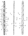
- Figs. 1 to 3 show a first embodiment of bone plate 10 for internal fixation of a bone fracture is shown.
- the plate is an elongate diaphyseal plate for fractures along a shaft portion of a long bone.
- the plate includes top and bottom surfaces 12, 14 and edges 16, 18 thereabout. Between the top and bottom (bone contacting) surfaces and along the length of the plate a plurality of screw holes 20, 22 are provided.
- Such screw holes may be variable angle, fixed angle, or combination variable and fixed angle screw holes.
- Commonly known fixators such as, e.g., fixed angle screws, variable angle screws, locking screws, and locking pegs, may be provided for use through the holes 20, 22.
- a plurality of multifunctional holes 24 for both K-wire and suture needle/suture material is also provided along the length of the plate adjacent the edges 16, 18 and communicate between the top and bottom surfaces 12, 14.
- Each multifunctional hole 24 generally includes a cylindrical portion 26 sized for closely receiving and guiding substantially along fixed axis A1 (e.g., ⁇ 3°) an appropriately sized stiff K-wire 28 (Fig. 8).
- the axis A1 is generally approximately normal to the top and/or bottom surfaces 12, 14 of the plate.
- portion 26 can be non-cylindrical, but otherwise shaped for substantially fixed-angle guidance of the K-wire along axis A1.
- the portion 26 may be provided with a regular polygonal cross-sectional (hexagonal, octagonal, etc.) which also guides the K-wire in a substantially fixed angle, as described.
- the cylindrical portion 26 has a circular upper opening 30 which is slightly flared at its entry to facilitate introduction of the K-wire 28 (Fig. 8) or suture needle 32 (Fig. 9, discussed below) and prevent stress concentration on suture material 34.
- the multifunctional hole 24 also includes a lateral channel (or lower recessed portion) 36 (i.e., directed toward the adjacent edge 16 of the plate) formed into the bottom surface 14 and the adjacent edge 16 of the plate such that a curved suture needle 32 and attached suture material 34 may be passed through the hole and laterally out of the side of the plate even when the plate is fixed to bone 38.
- the lateral channel 36 preferably assumes approximately half the height of the plate.
- the surface of the lateral channel 36 is defined by the inner surface of a toroidal section; i.e., suture guide surface 40 is concave across its width, as shown at the exit of the channel 36 in Fig. 5.
- all surfaces along the suture channel are broken or radiussed.
- a plurality of the multifunctional holes 24 may be arranged adjacent the edges 16, 18 of the plate 10 in staggered arrangement.
- the alternating arrangement substantially maintains the longitudinal and torsional stiffness of the plate.
- the multifunctional holes 124a, 124b may be spaced apart along the fixation plate 110 in an arrangement of opposed pairs. At each opposed pair of multifunctional holes 124a, 124b, the plate develops areas of decreased longitudinal stiffness as a result of the opposed lateral recesses 136a, 136b at the bottom surface 114 of the plate.
- Fig. 12 is a view across an area of decreased longitudinal stiffness. The decreased stiffness at such areas allows the plate to bend to conform to the shape of the bone when the plate is attached to the bone with fixators.
- Such plate may additionally include staggered holes 124c as well.
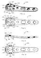
- Figs. 13 to 16 show a third embodiment of the invention.
- the specific plate 210 shown, by way of example, is a metaphyseal plate for fixation of humeral fractures.
- the plate includes top and bottom surfaces 212, 214.
- three closely spaced pairs of multifunctional holes 224 are shown located around the peripheral edge 216 of the head portion 218 of the plate 210.
- the cylindrical K-wire guiding portion 226 of a multifunctional hole is oriented at an oblique angle along axis A2 relative to the top and bottom surfaces 212, 214 of the plate.
- At the bottom surface 214 of the plate a wide lateral channel or recess 236 is provided and encompasses the exits of both K-wire guiding portions 226 of the holes.
Landscapes
- Health & Medical Sciences (AREA)
- Orthopedic Medicine & Surgery (AREA)
- Surgery (AREA)
- Life Sciences & Earth Sciences (AREA)
- Heart & Thoracic Surgery (AREA)
- Animal Behavior & Ethology (AREA)
- Engineering & Computer Science (AREA)
- Biomedical Technology (AREA)
- Neurology (AREA)
- Medical Informatics (AREA)
- Molecular Biology (AREA)
- Nuclear Medicine, Radiotherapy & Molecular Imaging (AREA)
- General Health & Medical Sciences (AREA)
- Public Health (AREA)
- Veterinary Medicine (AREA)
- Surgical Instruments (AREA)
- Laminated Bodies (AREA)
- Absorbent Articles And Supports Therefor (AREA)
Abstract
Description
- This invention relates to a fracture fixation plate, in particular which can be used with K-wires and/or suture material.
- Fracture fixation plates are common in the industry. Such plates are use to bridge across fractures, stabilizing fragments for healing. Fixation plates may be in the form of fragment plates which are generally used along the diaphysis of long bones or anatomically specific metaphyseal plates which are contoured for the articulating end of long bones.
The plates are generally provided with a plurality of screw holes at which the plates can be secured to the bone with screws or other fasteners. The holes may be locking holes, non-locking holes, combination holes (which can be locking or non-locking depending upon the fastener which is used), and a combination of any of the above. - It is common for fixation plates to include K-wire holes. Stiff K-wires are often used to temporarily secure a plate to the bone prior to and during fixation by the fasteners. The K-wires are then removed.
- In addition, it is known to provide fixed angle K-wire holes that have a cylindrical bore and which are sized to closely fit with K-wires so as to guide K-wires in a predefined angular orientation. Such orientation is closely related to the angle of one or more of the fasteners such that the path of the inserted K-wires anticipates the path of the fasteners. Then, when viewing the plate and inserted K-wires under fluoroscopy, the surgeon is provided with visual indication of whether the fasteners, once inserted, will be properly aligned with the anatomy. Such a technique is disclosed in
US-A-2005/0065524 . - Furthermore, depending upon the surgical procedure, the surgeon may need to incise the insertions of certain muscles to facilitate reduction of the fractured bone and to provide access for attachment of the plate to the bone. For example, in a procedure to fixate a proximal humeral fracture, the deltoid and pectoralis muscle insertions are commonly incised and after fixing the plate to the bone, the deltoid and pectoralis tendons may be fixed to the plate to reconstruct the musculature. As such, it is known to provide a plate with suture holes for receiving a suture needle and suture material, e.g., cord or cable. Suture holes are designed differently than K-wires holes. Rather than have structure for fixed angle guidance, the suture holes are heavily chamfered for prevent damage to the suture material.
- Thus, fixation plates are often replete with holes with dedicated functionality. Such holes crowd the plate surface, often making it difficult for a surgeon to identify which holes are to be used for which purpose. In addition, there may not be sufficient space on the plate to place the holes at the optimal locations for the desired purposes. Furthermore, the number of holes dedicated to each function may result in a plate that is weaker than desired for a particular application.
-
US-A-2005/0261688 discloses a plate having holes that are indicated to be for either guide wires or suture, thereby reducing the total number of holes. However, there is no disclosure that the holes are intended to guide stiff wires at a fixed angle. In addition, the design of the holes does not permit a suture needle to be inserted between the bone and the bone contacting surface of the plate after the plate is positioned against or attached to the bone. Suture holes which permit suture needle passage after the plate is fixed to the bone generally include a bottom clearance for the needle, as in the product sold under the trade mark Humeral SuturePlate by Arthrex Inc. - The present invention provides a bone plate for internal fixation of a bone fracture includes top and bottom surfaces and an edge. At least one multifunctional hole is provided along the edge and communicates between the top and bottom surfaces. The hole generally includes a cylindrical portion for closely receiving and guiding a stiff K-wire in a fixed angle. The hole also includes a lateral channel or recess formed into the bottom surface and an edge of the plate such that a curved suture needle and attached suture material may be passed through the hole and out of the side of the plate even when the plate is fixed to the bone. A plurality of multifunctional holes may be arranged along the edges of the plate, either closely spaced, e.g. in a metaphyseal plate, or spaced apart along sides of a diaphyseal plate. If arranged in a staggered manner along opposed sides, the plate maintains its longitudinal and torsional stiffness, whereas if the multifunctional holes are in an opposing arrangement, the plate develops areas of decreased stiffness at which the plate can bend to conform to the anatomy when coupled to the bone.
- Accordingly, in one aspect, the invention provides a bone plate for fixation of a bone fracture, comprising a bone plate for internal fixation of a bone fracture, the plate having top and bottom surfaces and at least one edge, in which the plate has a plurality of screw holes extending between the top and bottom surfaces for receiving fixators to couple the plate to the bone, and in which the plate has at least one multifunctional hole extending through it, the multifunctional hole including a wire guide portion which is structured to guide a stiff wire at a substantially fixed angle relative to the plate and a lateral recess extending from the guide portion to an adjacent edge, the lateral recess open to the bottom surface of the plate.
- In another aspect, the invention provides a bone plate for internal fixation of a bone fracture, for use with a stiff wire and a suture needle, the plate including top and bottom surfaces and a peripheral edge thereabout, and having a plurality of screw holes extending between the top and bottom surfaces for receiving fixators to couple the plate to the bone, the plate including:
- a first wire guide structured to guide the stiff wire at a substantially fixed angle relative to the plate,
- a second wire guide structured to guide the stiff wire at a substantially fixed angle relative to the plate, each of the first and second wire guides having an entry and an exit, and
- a recess extending from the exits of the first and second guides to the peripheral edge,
- In a further aspect, the invention provides a bone plate for fixation of a bone fracture, comprising a bone plate for internal fracture fixation, the plate including at least one multifunctional hole including both guide means for guiding a stiff wire at a substantially fixed angle and needle exit means for exiting a curved suture needle out of the multifunctional hole and out of a periphery of the plate after the plate has been coupled substantially flush against the bone.
- In another aspect, the invention provides a bone plate for fixation of a bone fracture, comprising a bone plate for internal fixation of a bone fracture, the plate including top and bottom surfaces and at least one edge thereabout, in which the plate defines a plurality of screw holes extending between the top and bottom surfaces for receiving fixators to couple the plate to the bone, and in which the plate has at least one multifunctional hole, the multifunctional hole including a wire guide portion which is structured to receive a stiff wire through the top and bottom surfaces of the plate and a lateral recess extending from the guide portion to an adjacent edge, the lateral recess open to the bottom surface of the plate.
- The fracture fixation plate of the invention has a multifunctional hole which can accommodate a K-wire at a fixed angle and which allows a suture needle to be inserted through the hole even after the plate has been fixed to the bone.
- The plate has a multifunctional hole that reduces the total number of holes required in a plate, thereby maintaining desired plate strength and allowing optimal placement of the holes within the plate.
- The multifunctional holes in the plate in an arrangement that minimise loss of longitudinal and torsional stiffness of the plate.
- The multifunctional holes in the plate can be provided in an arrangement that increases flexibility of the plate at specific locations.
- The multifunctional hole configuration can minimise stress concentration to sutures extending through it.
- The multifunctional hole feature of the invention can be provided in metaphyseal plates or in diaphyseal plates.
- Embodiments of the invention will now be described by way of example with reference to the accompanying drawings, in which:
- Fig. 1 is a top view of a first embodiment of a bone plate including a multifunctional hole according the invention;
- Fig. 2 is a side elevation view of the first embodiment of the bone plate;
- Fig. 3 is a bottom view of the first embodiment of the bone plate;
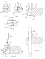
- Fig. 4 is an enlarged top view of a multifunctional hole in a bone plate;
- Fig. 5 is an enlarged side elevation of the multifunctional hole;
- Fig. 6 is an enlarged bottom view of the multifunctional hole;
- Fig. 7 is a section view across line 7-7 in Fig. 1;
- Fig. 8 is a view similar to Fig. 7, shown with the bone plate positioned on bone and a K-wire held within a fixed-angle with the multifunctional hole;
- Fig. 9 is a view similar to Fig. 7, shown with the bone plate positioned on bone and a suture needle extending through the multifunctional hole;
- Fig. 10 is a top view of a second embodiment of a bone plate with a multifunctional hole;
- Fig. 11 is a bottom view of the second embodiment of the bone plate;
- Fig. 12 is a section view across line 12-12 in Fig. 10;
- Fig. 13 is a perspective view of a third embodiment of a bone plate including a multifunctional hole according the invention;
- Fig. 14 is a top view of the third embodiment of a bone plate;
- Fig. 15 is a longitudinal section view of the third embodiment of the bone plate; and
- Fig. 16 is a bottom view of the third embodiment of the bone plate.
- Referring to the drawings, Figs. 1 to 3 show a first embodiment of
bone plate 10 for internal fixation of a bone fracture is shown. The plate is an elongate diaphyseal plate for fractures along a shaft portion of a long bone. The plate includes top andbottom surfaces edges holes - Referring to Figs. 2 through 9, a plurality of
multifunctional holes 24 for both K-wire and suture needle/suture material is also provided along the length of the plate adjacent theedges bottom surfaces multifunctional hole 24 generally includes acylindrical portion 26 sized for closely receiving and guiding substantially along fixed axis A1 (e.g., ±3°) an appropriately sized stiff K-wire 28 (Fig. 8). The axis A1 is generally approximately normal to the top and/or bottom surfaces 12, 14 of the plate. As an alternative,portion 26 can be non-cylindrical, but otherwise shaped for substantially fixed-angle guidance of the K-wire along axis A1. For example, theportion 26 may be provided with a regular polygonal cross-sectional (hexagonal, octagonal, etc.) which also guides the K-wire in a substantially fixed angle, as described. Thecylindrical portion 26 has a circularupper opening 30 which is slightly flared at its entry to facilitate introduction of the K-wire 28 (Fig. 8) or suture needle 32 (Fig. 9, discussed below) and prevent stress concentration onsuture material 34. Themultifunctional hole 24 also includes a lateral channel (or lower recessed portion) 36 (i.e., directed toward theadjacent edge 16 of the plate) formed into thebottom surface 14 and theadjacent edge 16 of the plate such that acurved suture needle 32 and attachedsuture material 34 may be passed through the hole and laterally out of the side of the plate even when the plate is fixed tobone 38. Thelateral channel 36 preferably assumes approximately half the height of the plate. The surface of thelateral channel 36 is defined by the inner surface of a toroidal section; i.e.,suture guide surface 40 is concave across its width, as shown at the exit of thechannel 36 in Fig. 5. In addition, all surfaces along the suture channel are broken or radiussed. Thus, whensuture material 34 is passed through the plate, stress concentrations on the suture material is limited and the likelihood of suture material breakage is minimized. - Referring back to Figs. 1 and 3, a plurality of the
multifunctional holes 24 may be arranged adjacent theedges plate 10 in staggered arrangement. The alternating arrangement substantially maintains the longitudinal and torsional stiffness of the plate. - Turning now to Figs. 10 to 12, according to second embodiment of the invention, it is also recognized that the
multifunctional holes 124a, 124b may be spaced apart along thefixation plate 110 in an arrangement of opposed pairs. At each opposed pair ofmultifunctional holes 124a, 124b, the plate develops areas of decreased longitudinal stiffness as a result of the opposedlateral recesses 136a, 136b at thebottom surface 114 of the plate. By way of example, Fig. 12 is a view across an area of decreased longitudinal stiffness. The decreased stiffness at such areas allows the plate to bend to conform to the shape of the bone when the plate is attached to the bone with fixators. Such plate may additionally includestaggered holes 124c as well. - Figs. 13 to 16 show a third embodiment of the invention. The
specific plate 210 shown, by way of example, is a metaphyseal plate for fixation of humeral fractures. The plate includes top andbottom surfaces plate 210, three closely spaced pairs ofmultifunctional holes 224 are shown located around theperipheral edge 216 of thehead portion 218 of theplate 210. The cylindrical K-wire guiding portion 226 of a multifunctional hole is oriented at an oblique angle along axis A2 relative to the top andbottom surfaces bottom surface 214 of the plate a wide lateral channel orrecess 236 is provided and encompasses the exits of both K-wire guiding portions 226 of the holes.
Claims (16)
- A bone plate for fixation of a bone fracture, comprising a bone plate for internal fixation of a bone fracture, the plate including top and bottom surfaces and at least one edge thereabout, in which the plate has a plurality of screw holes extending between the top and bottom surfaces for receiving fixators to couple the plate to the bone, and in which the plate has at least one multifunctional hole extending through it, the multifunctional hole including a wire guide portion which is structured to guide a stiff wire at a substantially fixed angle relative to the plate and a lateral recess extending from the guide portion to an adjacent edge, the lateral recess open to the bottom surface of the plate.
- A bone plate according to claim 1, in which the guide portion is cylindrical.
- A bone plate according to claim 1, in which the guide portion defines an axis that is normal to at least one of the top and bottom surfaces of the plate.
- A bone plate according to claim 1, in which the guide portion defines an axis that is oblique relative to at least one of the top and bottom surfaces of the plate.
- A bone plate according to claim 1, in which the guide portion has a flared opening at the top surface.
- A bone plate according to claim 1, in which the plate has a height, and at the adjacent edge the lateral recess assumes approximately half the height of the plate.
- A bone plate according to claim 1, in which the lateral recess includes a curved suture guide surface.
- A bone plate according to claim 1, in which the exit of the lateral recess at the adjacent edge is concavely curved.
- A bone plate according to claim 1, which includes a plurality of the multifunctional holes, spaced apart along the length of the plate.
- A bone plate according to claim 1, which includes a plurality of the multifunctional holes, in a staggered arrangement the length of the plate.
- A bone plate according to claim 1, which includes a plurality of the multifunctional holes which are arranged in pairs, with the holes of each pair located along respective edges of the plate, directly across from one another.
- A bone plate according to claim 1, in which the plate is a diaphyseal plate or a metaphyseal plate.
- A bone plate for internal fixation of a bone fracture, for use with a stiff wire and a suture needle, the plate including top and bottom surfaces and a peripheral edge thereabout, and having a plurality of screw holes extending between the top and bottom surfaces for receiving fixators to couple the plate to the bone, the plate including:a first wire guide structured to guide the stiff wire at a substantially fixed angle relative to the plate,a second wire guide structured to guide the stiff wire at a substantially fixed angle relative to the plate, each of the first and second wire guides having an entry and an exit, anda recess extending from the exits of the first and second guides to the peripheral edge,in which the suture needle may be passed through either of the first and second wire guides and exit laterally of the plate through the recess after the bottom surface of the plate has been coupled substantially flush against the bone.
- A bone plate according to claim 13, in which at least one of the first and second wire guides defines a fixed angle axis for the stiff wire that is oblique relative to one of the top and bottom surfaces of the plate.
- A bone plate according to claim 13, in which the plate is a metaphyseal plate including a head portion and the first and second wire guides and recess are provided together in the head portion.
- A bone plate according to claim 13, in which a plurality of combinations of the first and second wire guides and recess are spaced apart about a periphery of the head portion.
Applications Claiming Priority (1)
| Application Number | Priority Date | Filing Date | Title |
|---|---|---|---|
| US11/379,646 US20070270849A1 (en) | 2006-04-21 | 2006-04-21 | Fixation Plate With Multifunctional Holes |
Publications (2)
| Publication Number | Publication Date |
|---|---|
| EP1847228A1 true EP1847228A1 (en) | 2007-10-24 |
| EP1847228B1 EP1847228B1 (en) | 2009-08-05 |
Family
ID=38229535
Family Applications (1)
| Application Number | Title | Priority Date | Filing Date |
|---|---|---|---|
| EP07251649A Revoked EP1847228B1 (en) | 2006-04-21 | 2007-04-19 | Fixation plate with multifunctional holes |
Country Status (6)
| Country | Link |
|---|---|
| US (1) | US20070270849A1 (en) |
| EP (1) | EP1847228B1 (en) |
| JP (1) | JP2007289698A (en) |
| AT (1) | ATE438350T1 (en) |
| AU (1) | AU2007201705A1 (en) |
| DE (1) | DE602007001821D1 (en) |
Cited By (17)
| Publication number | Priority date | Publication date | Assignee | Title |
|---|---|---|---|---|
| EP2092904A1 (en) * | 2008-02-22 | 2009-08-26 | Prévôt, Bertrand | Trochanter plate |
| CN103142301A (en) * | 2013-03-26 | 2013-06-12 | 江苏荷普医疗器械有限公司 | Angular bone fracture plate |
| US8597362B2 (en) | 2009-08-27 | 2013-12-03 | Cotera, Inc. | Method and apparatus for force redistribution in articular joints |
| KR200472918Y1 (en) * | 2009-07-07 | 2014-05-29 | 짐머 게엠베하 | A plate for the treatment of bonb fractures |
| US8845724B2 (en) | 2009-08-27 | 2014-09-30 | Cotera, Inc. | Method and apparatus for altering biomechanics of the articular joints |
| CN104688319A (en) * | 2015-03-17 | 2015-06-10 | 苏州瑞华医院有限公司 | Lateral malleolus bone plate |
| US9468466B1 (en) | 2012-08-24 | 2016-10-18 | Cotera, Inc. | Method and apparatus for altering biomechanics of the spine |
| US9655648B2 (en) | 2007-05-01 | 2017-05-23 | Moximed, Inc. | Femoral and tibial base components |
| US9668868B2 (en) | 2009-08-27 | 2017-06-06 | Cotera, Inc. | Apparatus and methods for treatment of patellofemoral conditions |
| US9700419B2 (en) | 2007-05-01 | 2017-07-11 | Moximed, Inc. | Extra-articular implantable mechanical energy absorbing systems and implantation method |
| US9814579B2 (en) | 2007-05-01 | 2017-11-14 | Moximed, Inc. | Unlinked implantable knee unloading device |
| US9861408B2 (en) | 2009-08-27 | 2018-01-09 | The Foundry, Llc | Method and apparatus for treating canine cruciate ligament disease |
| US9907645B2 (en) | 2007-05-01 | 2018-03-06 | Moximed, Inc. | Adjustable absorber designs for implantable device |
| US10010421B2 (en) | 2007-05-01 | 2018-07-03 | Moximed, Inc. | Extra-articular implantable mechanical energy absorbing systems |
| US10327816B2 (en) | 2007-05-01 | 2019-06-25 | Moximed, Inc. | Adjustable absorber designs for implantable device |
| US10349980B2 (en) | 2009-08-27 | 2019-07-16 | The Foundry, Llc | Method and apparatus for altering biomechanics of the shoulder |
| US10383736B2 (en) | 2007-05-01 | 2019-08-20 | Moximed, Inc. | Femoral and tibial base components |
Families Citing this family (48)
| Publication number | Priority date | Publication date | Assignee | Title |
|---|---|---|---|---|
| US20110245928A1 (en) | 2010-04-06 | 2011-10-06 | Moximed, Inc. | Femoral and Tibial Bases |
| EP2397095B1 (en) | 2007-11-02 | 2015-05-06 | DePuy Products, Inc. | Elbow fracture fixation system |
| KR100999789B1 (en) | 2008-05-14 | 2010-12-08 | (주)트라디메딕스 | Metal plate for bonesetting |
| US8777998B2 (en) * | 2009-02-23 | 2014-07-15 | Orthopediatrics Corp. | Pediatric long bone support or fixation plate |
| BR112013003543A2 (en) * | 2010-08-17 | 2016-06-28 | Redyns Medical Llc | method and apparatus for attaching soft tissue to bone |
| US8709092B2 (en) | 2011-02-16 | 2014-04-29 | Genesis Medical Devices, LLC | Periprosthetic fracture management enhancements |
| US9044270B2 (en) | 2011-03-29 | 2015-06-02 | Moximed, Inc. | Apparatus for controlling a load on a hip joint |
| US8790378B2 (en) | 2012-02-02 | 2014-07-29 | Biomet C.V. | Distal radius fracture fixation plate with integrated and adjustable volar ulnar facet support |
| US9480475B2 (en) | 2012-08-15 | 2016-11-01 | DePuy Synthes Products, Inc. | Bone plate suture anchor |
| US9730686B2 (en) * | 2014-09-03 | 2017-08-15 | Biomet C.V. | System and method of soft tissue anchoring to metaphyseal bone plate |
| USD779065S1 (en) | 2014-10-08 | 2017-02-14 | Nuvasive, Inc. | Anterior cervical bone plate |
| US11197682B2 (en) | 2015-08-27 | 2021-12-14 | Globus Medical, Inc. | Proximal humeral stabilization system |
| US11076898B2 (en) | 2015-08-27 | 2021-08-03 | Globus Medical, Inc. | Proximal humeral stabilization system |
| US10687874B2 (en) | 2015-08-27 | 2020-06-23 | Globus Medical, Inc | Proximal humeral stabilization system |
| US10130402B2 (en) | 2015-09-25 | 2018-11-20 | Globus Medical, Inc. | Bone fixation devices having a locking feature |
| US9974581B2 (en) | 2015-11-20 | 2018-05-22 | Globus Medical, Inc. | Expandable intramedullary systems and methods of using the same |
| US20170202586A1 (en) * | 2015-12-11 | 2017-07-20 | DePuy Synthes Products, Inc. | Composite implant trial |
| US9795411B2 (en) | 2016-03-02 | 2017-10-24 | Globus Medical, Inc. | Fixators for bone stabilization and associated systems and methods |
| US10531905B2 (en) | 2016-04-19 | 2020-01-14 | Globus Medical, Inc. | Implantable compression screws |
| US10575884B2 (en) | 2016-08-17 | 2020-03-03 | Globus Medical, Inc. | Fracture plates, systems, and methods |
| US11197701B2 (en) | 2016-08-17 | 2021-12-14 | Globus Medical, Inc. | Stabilization systems |
| US10383668B2 (en) | 2016-08-17 | 2019-08-20 | Globus Medical, Inc. | Volar distal radius stabilization system |
| US11432857B2 (en) * | 2016-08-17 | 2022-09-06 | Globus Medical, Inc. | Stabilization systems |
| US11331128B2 (en) | 2016-08-17 | 2022-05-17 | Globus Medical Inc. | Distal radius stabilization system |
| US10420596B2 (en) | 2016-08-17 | 2019-09-24 | Globus Medical, Inc. | Volar distal radius stabilization system |
| US10751098B2 (en) | 2016-08-17 | 2020-08-25 | Globus Medical Inc. | Stabilization systems |
| US11213327B2 (en) * | 2016-08-17 | 2022-01-04 | Globus Medical, Inc. | Fracture plates, systems, and methods |
| US10687873B2 (en) | 2016-08-17 | 2020-06-23 | Globus Medical Inc. | Stabilization systems |
| US11141204B2 (en) | 2016-08-17 | 2021-10-12 | Globus Medical Inc. | Wrist stabilization systems |
| US10299847B2 (en) | 2016-09-22 | 2019-05-28 | Globus Medical, Inc. | Systems and methods for intramedullary nail implantation |
| TWI599340B (en) * | 2016-11-01 | 2017-09-21 | 財團法人金屬工業研究發展中心 | Locking plate |
| EP3348218B1 (en) * | 2017-01-13 | 2022-11-16 | Globus Medical, Inc. | Stabilization systems |
| US10881438B2 (en) | 2017-03-10 | 2021-01-05 | Globus Medical, Inc. | Clavicle fixation system |
| US10905477B2 (en) * | 2017-03-13 | 2021-02-02 | Globus Medical, Inc. | Bone stabilization systems |
| AU2018236155B2 (en) * | 2017-03-13 | 2023-04-13 | DePuy Synthes Products, Inc. | Proximal femur plate system |
| US10368928B2 (en) | 2017-03-13 | 2019-08-06 | Globus Medical, Inc. | Bone stabilization systems |
| CN111095659B (en) | 2017-08-31 | 2023-05-09 | 株式会社村田制作所 | Secondary battery and method for manufacturing same |
| US10856920B2 (en) | 2017-09-13 | 2020-12-08 | Globus Medical Inc. | Bone stabilization systems |
| US11096730B2 (en) | 2017-09-13 | 2021-08-24 | Globus Medical Inc. | Bone stabilization systems |
| US10881436B2 (en) | 2017-10-27 | 2021-01-05 | Wright Medical Technology, Inc. | Implant with intramedullary portion and offset extramedullary portion |
| US11071570B2 (en) | 2018-03-02 | 2021-07-27 | Globus Medical, Inc. | Distal tibial plating system |
| US11224468B2 (en) | 2018-03-02 | 2022-01-18 | Globus Medical, Inc. | Distal tibial plating system |
| US11141172B2 (en) | 2018-04-11 | 2021-10-12 | Globus Medical, Inc. | Method and apparatus for locking a drill guide in a polyaxial hole |
| US11202663B2 (en) | 2019-02-13 | 2021-12-21 | Globus Medical, Inc. | Proximal humeral stabilization systems and methods thereof |
| US11944361B2 (en) | 2019-08-09 | 2024-04-02 | DePuy Synthes Products, Inc. | Bone plate with structures for attachment of sutures |
| US11129627B2 (en) | 2019-10-30 | 2021-09-28 | Globus Medical, Inc. | Method and apparatus for inserting a bone plate |
| US11723647B2 (en) | 2019-12-17 | 2023-08-15 | Globus Medical, Inc. | Syndesmosis fixation assembly |
| US12064150B2 (en) | 2022-01-19 | 2024-08-20 | Globus Medical Inc. | System and method for treating bone fractures |
Citations (4)
| Publication number | Priority date | Publication date | Assignee | Title |
|---|---|---|---|---|
| WO2002096309A1 (en) * | 2001-05-28 | 2002-12-05 | Synthes Ag Chur | Bone plate for the fixation of fractures of the proximal humerus |
| US20050182405A1 (en) | 2004-01-23 | 2005-08-18 | Orbay Jorge L. | System for stabilization of fractures of convex articular bone surfaces including subchondral support structure |
| US20050234458A1 (en) * | 2004-04-19 | 2005-10-20 | Huebner Randall J | Expanded stabilization of bones |
| US20050261688A1 (en) | 2004-05-11 | 2005-11-24 | Grady Mark P Jr | Bone plate |
Family Cites Families (12)
| Publication number | Priority date | Publication date | Assignee | Title |
|---|---|---|---|---|
| US4219027A (en) * | 1979-01-16 | 1980-08-26 | Nasa | Subcutaneous electrode structure |
| DE8431616U1 (en) * | 1984-10-27 | 1984-12-20 | Howmedica International, Inc. Zweigniederlassung Kiel, 2314 Schönkirchen | Plate for osteosynthesis |
| CH673762A5 (en) * | 1987-12-02 | 1990-04-12 | Synthes Ag | |
| AU733432B2 (en) * | 1998-05-12 | 2001-05-17 | Synthes Gmbh | Bone augmentation device |
| US6093201A (en) * | 1999-01-19 | 2000-07-25 | Ethicon, Inc. | Biocompatible absorbable polymer plating system for tissue fixation |
| DE60007758T2 (en) * | 1999-09-13 | 2004-09-23 | Synthes Ag Chur, Chur | BONE PLATE DEVICE |
| US6514274B1 (en) * | 2000-02-25 | 2003-02-04 | Arthrotek, Inc. | Method and apparatus for rotator cuff repair |
| US6283969B1 (en) * | 2000-03-10 | 2001-09-04 | Wright Medical Technology, Inc. | Bone plating system |
| US20050049594A1 (en) * | 2001-04-20 | 2005-03-03 | Wack Michael A. | Dual locking plate and associated method |
| US7294130B2 (en) * | 2003-03-27 | 2007-11-13 | Depuy Products, Inc. | Distal radius fracture fixation plate having K-wire hole structured to fix a K-wire in one dimension relative to the plate |
| US20060229620A1 (en) * | 2005-03-03 | 2006-10-12 | Accin Corporation | Method and apparatus for providing a retainer for a bone stabilization device |
| US20060276896A1 (en) * | 2005-06-02 | 2006-12-07 | Medicinelodge, Inc. | Bone implants with integrated line locks |
-
2006
- 2006-04-21 US US11/379,646 patent/US20070270849A1/en not_active Abandoned
-
2007
- 2007-04-17 AU AU2007201705A patent/AU2007201705A1/en not_active Abandoned
- 2007-04-19 EP EP07251649A patent/EP1847228B1/en not_active Revoked
- 2007-04-19 DE DE602007001821T patent/DE602007001821D1/en not_active Expired - Fee Related
- 2007-04-19 AT AT07251649T patent/ATE438350T1/en not_active IP Right Cessation
- 2007-04-20 JP JP2007112139A patent/JP2007289698A/en active Pending
Patent Citations (4)
| Publication number | Priority date | Publication date | Assignee | Title |
|---|---|---|---|---|
| WO2002096309A1 (en) * | 2001-05-28 | 2002-12-05 | Synthes Ag Chur | Bone plate for the fixation of fractures of the proximal humerus |
| US20050182405A1 (en) | 2004-01-23 | 2005-08-18 | Orbay Jorge L. | System for stabilization of fractures of convex articular bone surfaces including subchondral support structure |
| US20050234458A1 (en) * | 2004-04-19 | 2005-10-20 | Huebner Randall J | Expanded stabilization of bones |
| US20050261688A1 (en) | 2004-05-11 | 2005-11-24 | Grady Mark P Jr | Bone plate |
Cited By (32)
| Publication number | Priority date | Publication date | Assignee | Title |
|---|---|---|---|---|
| US9655648B2 (en) | 2007-05-01 | 2017-05-23 | Moximed, Inc. | Femoral and tibial base components |
| US10070964B2 (en) | 2007-05-01 | 2018-09-11 | Moximed, Inc. | Extra-articular implantable mechanical energy absorbing systems and implantation method |
| US10736746B2 (en) | 2007-05-01 | 2020-08-11 | Moximed, Inc. | Extra-articular implantable mechanical energy absorbing systems |
| US9814579B2 (en) | 2007-05-01 | 2017-11-14 | Moximed, Inc. | Unlinked implantable knee unloading device |
| US10639161B2 (en) | 2007-05-01 | 2020-05-05 | Moximed, Inc. | Extra-articular implantable load sharing systems |
| US10596007B2 (en) | 2007-05-01 | 2020-03-24 | Moximed, Inc. | Extra-articular implantable mechanical energy absorbing systems and implantation method |
| US11389298B2 (en) | 2007-05-01 | 2022-07-19 | Moximed, Inc. | Extra-articular implantable mechanical energy absorbing systems |
| US10327816B2 (en) | 2007-05-01 | 2019-06-25 | Moximed, Inc. | Adjustable absorber designs for implantable device |
| US10383736B2 (en) | 2007-05-01 | 2019-08-20 | Moximed, Inc. | Femoral and tibial base components |
| US9907645B2 (en) | 2007-05-01 | 2018-03-06 | Moximed, Inc. | Adjustable absorber designs for implantable device |
| US10022154B2 (en) | 2007-05-01 | 2018-07-17 | Moximed, Inc. | Femoral and tibial base components |
| US9700419B2 (en) | 2007-05-01 | 2017-07-11 | Moximed, Inc. | Extra-articular implantable mechanical energy absorbing systems and implantation method |
| US10010421B2 (en) | 2007-05-01 | 2018-07-03 | Moximed, Inc. | Extra-articular implantable mechanical energy absorbing systems |
| EP2092904A1 (en) * | 2008-02-22 | 2009-08-26 | Prévôt, Bertrand | Trochanter plate |
| KR200472918Y1 (en) * | 2009-07-07 | 2014-05-29 | 짐머 게엠베하 | A plate for the treatment of bonb fractures |
| US9931136B2 (en) | 2009-08-27 | 2018-04-03 | The Foundry, Llc | Method and apparatus for altering biomechanics of articular joints |
| US8845724B2 (en) | 2009-08-27 | 2014-09-30 | Cotera, Inc. | Method and apparatus for altering biomechanics of the articular joints |
| US9795410B2 (en) | 2009-08-27 | 2017-10-24 | Cotera, Inc. | Method and apparatus for force redistribution in articular joints |
| US9668868B2 (en) | 2009-08-27 | 2017-06-06 | Cotera, Inc. | Apparatus and methods for treatment of patellofemoral conditions |
| US11730519B2 (en) | 2009-08-27 | 2023-08-22 | The Foundry, Llc | Method and apparatus for force redistribution in articular joints |
| US9278004B2 (en) | 2009-08-27 | 2016-03-08 | Cotera, Inc. | Method and apparatus for altering biomechanics of the articular joints |
| US10349980B2 (en) | 2009-08-27 | 2019-07-16 | The Foundry, Llc | Method and apparatus for altering biomechanics of the shoulder |
| US9114016B2 (en) | 2009-08-27 | 2015-08-25 | Cotera, Inc. | Method and apparatus for altering biomechanics of the articular joints |
| US11517360B2 (en) | 2009-08-27 | 2022-12-06 | The Foundry, Llc | Method and apparatus for treating canine cruciate ligament disease |
| US9861408B2 (en) | 2009-08-27 | 2018-01-09 | The Foundry, Llc | Method and apparatus for treating canine cruciate ligament disease |
| US10695094B2 (en) | 2009-08-27 | 2020-06-30 | The Foundry, Llc | Method and apparatus for altering biomechanics of articular joints |
| US8597362B2 (en) | 2009-08-27 | 2013-12-03 | Cotera, Inc. | Method and apparatus for force redistribution in articular joints |
| US10898237B2 (en) | 2012-08-24 | 2021-01-26 | The Foundry, Llc | Method and apparatus for altering biomechanics of the spine |
| US9468466B1 (en) | 2012-08-24 | 2016-10-18 | Cotera, Inc. | Method and apparatus for altering biomechanics of the spine |
| CN103142301A (en) * | 2013-03-26 | 2013-06-12 | 江苏荷普医疗器械有限公司 | Angular bone fracture plate |
| CN104688319A (en) * | 2015-03-17 | 2015-06-10 | 苏州瑞华医院有限公司 | Lateral malleolus bone plate |
| US11241256B2 (en) | 2015-10-15 | 2022-02-08 | The Foundry, Llc | Method and apparatus for altering biomechanics of the shoulder |
Also Published As
| Publication number | Publication date |
|---|---|
| ATE438350T1 (en) | 2009-08-15 |
| JP2007289698A (en) | 2007-11-08 |
| AU2007201705A1 (en) | 2007-11-08 |
| EP1847228B1 (en) | 2009-08-05 |
| DE602007001821D1 (en) | 2009-09-17 |
| US20070270849A1 (en) | 2007-11-22 |
Similar Documents
| Publication | Publication Date | Title |
|---|---|---|
| EP1847228B1 (en) | Fixation plate with multifunctional holes | |
| US20230044584A1 (en) | Fracture fixation plate and system | |
| US6364882B1 (en) | Volar fixation system | |
| US9370386B2 (en) | Plating concept for distal radial fractures | |
| KR101144067B1 (en) | Anatomical distal radius fracture fixation plate and methods of using the same | |
| US9492213B2 (en) | Volar fixation system | |
| EP1764053B1 (en) | Bone fixation plate with complex suture anchor locations | |
| US8764808B2 (en) | Bone fixation system | |
| US6652528B2 (en) | Intramedullary nail with modular sleeve | |
| US7938850B2 (en) | Nail plate | |
| US7896886B2 (en) | Nail plate and implantation jig therefor | |
| US8728126B2 (en) | Bone fixation system and method | |
| US8668693B2 (en) | Fixation device for proximal elbow fractures and method of using same | |
| US8961574B2 (en) | Bone plate with hook portion | |
| US10537371B2 (en) | Wrist plate and drill guide | |
| RU2762481C1 (en) | Palmar (volar) fixation device for osteosynthesis in the treatment of fractures of the distal radius |
Legal Events
| Date | Code | Title | Description |
|---|---|---|---|
| PUAI | Public reference made under article 153(3) epc to a published international application that has entered the european phase |
Free format text: ORIGINAL CODE: 0009012 |
|
| AK | Designated contracting states |
Kind code of ref document: A1 Designated state(s): AT BE BG CH CY CZ DE DK EE ES FI FR GB GR HU IE IS IT LI LT LU LV MC MT NL PL PT RO SE SI SK TR |
|
| AX | Request for extension of the european patent |
Extension state: AL BA HR MK YU |
|
| 17P | Request for examination filed |
Effective date: 20080401 |
|
| 17Q | First examination report despatched |
Effective date: 20080522 |
|
| AKX | Designation fees paid |
Designated state(s): AT BE BG CH CY CZ DE DK EE ES FI FR GB GR HU IE IS IT LI LT LU LV MC MT NL PL PT RO SE SI SK TR |
|
| GRAP | Despatch of communication of intention to grant a patent |
Free format text: ORIGINAL CODE: EPIDOSNIGR1 |
|
| GRAS | Grant fee paid |
Free format text: ORIGINAL CODE: EPIDOSNIGR3 |
|
| GRAA | (expected) grant |
Free format text: ORIGINAL CODE: 0009210 |
|
| AK | Designated contracting states |
Kind code of ref document: B1 Designated state(s): AT BE BG CH CY CZ DE DK EE ES FI FR GB GR HU IE IS IT LI LT LU LV MC MT NL PL PT RO SE SI SK TR |
|
| REG | Reference to a national code |
Ref country code: GB Ref legal event code: FG4D |
|
| REG | Reference to a national code |
Ref country code: CH Ref legal event code: EP Ref country code: CH Ref legal event code: NV Representative=s name: E. BLUM & CO. AG PATENT- UND MARKENANWAELTE VSP |
|
| REG | Reference to a national code |
Ref country code: IE Ref legal event code: FG4D |
|
| REF | Corresponds to: |
Ref document number: 602007001821 Country of ref document: DE Date of ref document: 20090917 Kind code of ref document: P |
|
| LTIE | Lt: invalidation of european patent or patent extension |
Effective date: 20090805 |
|
| PG25 | Lapsed in a contracting state [announced via postgrant information from national office to epo] |
Ref country code: ES Free format text: LAPSE BECAUSE OF FAILURE TO SUBMIT A TRANSLATION OF THE DESCRIPTION OR TO PAY THE FEE WITHIN THE PRESCRIBED TIME-LIMIT Effective date: 20091116 Ref country code: IS Free format text: LAPSE BECAUSE OF FAILURE TO SUBMIT A TRANSLATION OF THE DESCRIPTION OR TO PAY THE FEE WITHIN THE PRESCRIBED TIME-LIMIT Effective date: 20091205 Ref country code: FI Free format text: LAPSE BECAUSE OF FAILURE TO SUBMIT A TRANSLATION OF THE DESCRIPTION OR TO PAY THE FEE WITHIN THE PRESCRIBED TIME-LIMIT Effective date: 20090805 Ref country code: AT Free format text: LAPSE BECAUSE OF FAILURE TO SUBMIT A TRANSLATION OF THE DESCRIPTION OR TO PAY THE FEE WITHIN THE PRESCRIBED TIME-LIMIT Effective date: 20090805 Ref country code: SE Free format text: LAPSE BECAUSE OF FAILURE TO SUBMIT A TRANSLATION OF THE DESCRIPTION OR TO PAY THE FEE WITHIN THE PRESCRIBED TIME-LIMIT Effective date: 20090805 Ref country code: LT Free format text: LAPSE BECAUSE OF FAILURE TO SUBMIT A TRANSLATION OF THE DESCRIPTION OR TO PAY THE FEE WITHIN THE PRESCRIBED TIME-LIMIT Effective date: 20090805 |
|
| NLV1 | Nl: lapsed or annulled due to failure to fulfill the requirements of art. 29p and 29m of the patents act | ||
| PG25 | Lapsed in a contracting state [announced via postgrant information from national office to epo] |
Ref country code: SI Free format text: LAPSE BECAUSE OF FAILURE TO SUBMIT A TRANSLATION OF THE DESCRIPTION OR TO PAY THE FEE WITHIN THE PRESCRIBED TIME-LIMIT Effective date: 20090805 Ref country code: LV Free format text: LAPSE BECAUSE OF FAILURE TO SUBMIT A TRANSLATION OF THE DESCRIPTION OR TO PAY THE FEE WITHIN THE PRESCRIBED TIME-LIMIT Effective date: 20090805 Ref country code: NL Free format text: LAPSE BECAUSE OF FAILURE TO SUBMIT A TRANSLATION OF THE DESCRIPTION OR TO PAY THE FEE WITHIN THE PRESCRIBED TIME-LIMIT Effective date: 20090805 Ref country code: PL Free format text: LAPSE BECAUSE OF FAILURE TO SUBMIT A TRANSLATION OF THE DESCRIPTION OR TO PAY THE FEE WITHIN THE PRESCRIBED TIME-LIMIT Effective date: 20090805 |
|
| PG25 | Lapsed in a contracting state [announced via postgrant information from national office to epo] |
Ref country code: BG Free format text: LAPSE BECAUSE OF FAILURE TO SUBMIT A TRANSLATION OF THE DESCRIPTION OR TO PAY THE FEE WITHIN THE PRESCRIBED TIME-LIMIT Effective date: 20091105 Ref country code: PT Free format text: LAPSE BECAUSE OF FAILURE TO SUBMIT A TRANSLATION OF THE DESCRIPTION OR TO PAY THE FEE WITHIN THE PRESCRIBED TIME-LIMIT Effective date: 20091205 |
|
| PLBI | Opposition filed |
Free format text: ORIGINAL CODE: 0009260 |
|
| PG25 | Lapsed in a contracting state [announced via postgrant information from national office to epo] |
Ref country code: RO Free format text: LAPSE BECAUSE OF FAILURE TO SUBMIT A TRANSLATION OF THE DESCRIPTION OR TO PAY THE FEE WITHIN THE PRESCRIBED TIME-LIMIT Effective date: 20090805 Ref country code: EE Free format text: LAPSE BECAUSE OF FAILURE TO SUBMIT A TRANSLATION OF THE DESCRIPTION OR TO PAY THE FEE WITHIN THE PRESCRIBED TIME-LIMIT Effective date: 20090805 Ref country code: CZ Free format text: LAPSE BECAUSE OF FAILURE TO SUBMIT A TRANSLATION OF THE DESCRIPTION OR TO PAY THE FEE WITHIN THE PRESCRIBED TIME-LIMIT Effective date: 20090805 Ref country code: DK Free format text: LAPSE BECAUSE OF FAILURE TO SUBMIT A TRANSLATION OF THE DESCRIPTION OR TO PAY THE FEE WITHIN THE PRESCRIBED TIME-LIMIT Effective date: 20090805 |
|
| PLBI | Opposition filed |
Free format text: ORIGINAL CODE: 0009260 |
|
| 26 | Opposition filed |
Opponent name: SMITH AND NEPHEW, INC. Effective date: 20100419 |
|
| PG25 | Lapsed in a contracting state [announced via postgrant information from national office to epo] |
Ref country code: SK Free format text: LAPSE BECAUSE OF FAILURE TO SUBMIT A TRANSLATION OF THE DESCRIPTION OR TO PAY THE FEE WITHIN THE PRESCRIBED TIME-LIMIT Effective date: 20090805 |
|
| 26 | Opposition filed |
Opponent name: SMITH AND NEPHEW, INC. Effective date: 20100419 Opponent name: SYNTHES GMBH Effective date: 20100427 |
|
| PLAX | Notice of opposition and request to file observation + time limit sent |
Free format text: ORIGINAL CODE: EPIDOSNOBS2 |
|
| PG25 | Lapsed in a contracting state [announced via postgrant information from national office to epo] |
Ref country code: BE Free format text: LAPSE BECAUSE OF FAILURE TO SUBMIT A TRANSLATION OF THE DESCRIPTION OR TO PAY THE FEE WITHIN THE PRESCRIBED TIME-LIMIT Effective date: 20090805 |
|
| PLAF | Information modified related to communication of a notice of opposition and request to file observations + time limit |
Free format text: ORIGINAL CODE: EPIDOSCOBS2 |
|
| PG25 | Lapsed in a contracting state [announced via postgrant information from national office to epo] |
Ref country code: GR Free format text: LAPSE BECAUSE OF FAILURE TO SUBMIT A TRANSLATION OF THE DESCRIPTION OR TO PAY THE FEE WITHIN THE PRESCRIBED TIME-LIMIT Effective date: 20091106 |
|
| PG25 | Lapsed in a contracting state [announced via postgrant information from national office to epo] |
Ref country code: MC Free format text: LAPSE BECAUSE OF NON-PAYMENT OF DUE FEES Effective date: 20100430 |
|
| REG | Reference to a national code |
Ref country code: FR Ref legal event code: ST Effective date: 20101230 |
|
| PG25 | Lapsed in a contracting state [announced via postgrant information from national office to epo] |
Ref country code: IE Free format text: LAPSE BECAUSE OF NON-PAYMENT OF DUE FEES Effective date: 20100419 |
|
| PG25 | Lapsed in a contracting state [announced via postgrant information from national office to epo] |
Ref country code: DE Free format text: LAPSE BECAUSE OF NON-PAYMENT OF DUE FEES Effective date: 20101103 |
|
| PG25 | Lapsed in a contracting state [announced via postgrant information from national office to epo] |
Ref country code: MT Free format text: LAPSE BECAUSE OF FAILURE TO SUBMIT A TRANSLATION OF THE DESCRIPTION OR TO PAY THE FEE WITHIN THE PRESCRIBED TIME-LIMIT Effective date: 20090805 |
|
| PLBB | Reply of patent proprietor to notice(s) of opposition received |
Free format text: ORIGINAL CODE: EPIDOSNOBS3 |
|
| RDAF | Communication despatched that patent is revoked |
Free format text: ORIGINAL CODE: EPIDOSNREV1 |
|
| REG | Reference to a national code |
Ref country code: CH Ref legal event code: PL |
|
| GBPC | Gb: european patent ceased through non-payment of renewal fee |
Effective date: 20110419 |
|
| PGFP | Annual fee paid to national office [announced via postgrant information from national office to epo] |
Ref country code: IT Payment date: 20100430 Year of fee payment: 4 |
|
| PG25 | Lapsed in a contracting state [announced via postgrant information from national office to epo] |
Ref country code: LI Free format text: LAPSE BECAUSE OF NON-PAYMENT OF DUE FEES Effective date: 20110430 Ref country code: CH Free format text: LAPSE BECAUSE OF NON-PAYMENT OF DUE FEES Effective date: 20110430 |
|
| PG25 | Lapsed in a contracting state [announced via postgrant information from national office to epo] |
Ref country code: GB Free format text: LAPSE BECAUSE OF NON-PAYMENT OF DUE FEES Effective date: 20110419 |
|
| RDAG | Patent revoked |
Free format text: ORIGINAL CODE: 0009271 |
|
| STAA | Information on the status of an ep patent application or granted ep patent |
Free format text: STATUS: PATENT REVOKED |
|
| 27W | Patent revoked |
Effective date: 20111202 |
|
| PG25 | Lapsed in a contracting state [announced via postgrant information from national office to epo] |
Ref country code: FR Free format text: LAPSE BECAUSE OF NON-PAYMENT OF DUE FEES Effective date: 20100430 |
|
| PG25 | Lapsed in a contracting state [announced via postgrant information from national office to epo] |
Ref country code: CY Free format text: LAPSE BECAUSE OF FAILURE TO SUBMIT A TRANSLATION OF THE DESCRIPTION OR TO PAY THE FEE WITHIN THE PRESCRIBED TIME-LIMIT Effective date: 20090805 |
|
| PG25 | Lapsed in a contracting state [announced via postgrant information from national office to epo] |
Ref country code: LU Free format text: LAPSE BECAUSE OF REVOCATION BY EPO Effective date: 20100419 Ref country code: HU Free format text: LAPSE BECAUSE OF FAILURE TO SUBMIT A TRANSLATION OF THE DESCRIPTION OR TO PAY THE FEE WITHIN THE PRESCRIBED TIME-LIMIT Effective date: 20100206 |