US8702714B2 - Instruments for total knee arthroplasty - Google Patents
Instruments for total knee arthroplasty Download PDFInfo
- Publication number
- US8702714B2 US8702714B2 US11/684,395 US68439507A US8702714B2 US 8702714 B2 US8702714 B2 US 8702714B2 US 68439507 A US68439507 A US 68439507A US 8702714 B2 US8702714 B2 US 8702714B2
- Authority
- US
- United States
- Prior art keywords
- rod
- resection
- resection guide
- engagement
- valgus
- Prior art date
- Legal status (The legal status is an assumption and is not a legal conclusion. Google has not performed a legal analysis and makes no representation as to the accuracy of the status listed.)
- Expired - Fee Related, expires
Links
Images


Classifications
-
- A—HUMAN NECESSITIES
- A61—MEDICAL OR VETERINARY SCIENCE; HYGIENE
- A61B—DIAGNOSIS; SURGERY; IDENTIFICATION
- A61B17/00—Surgical instruments, devices or methods, e.g. tourniquets
- A61B17/16—Bone cutting, breaking or removal means other than saws, e.g. Osteoclasts; Drills or chisels for bones; Trepans
- A61B17/17—Guides or aligning means for drills, mills, pins or wires
- A61B17/1739—Guides or aligning means for drills, mills, pins or wires specially adapted for particular parts of the body
- A61B17/1764—Guides or aligning means for drills, mills, pins or wires specially adapted for particular parts of the body for the knee
-
- A—HUMAN NECESSITIES
- A61—MEDICAL OR VETERINARY SCIENCE; HYGIENE
- A61B—DIAGNOSIS; SURGERY; IDENTIFICATION
- A61B17/00—Surgical instruments, devices or methods, e.g. tourniquets
- A61B17/14—Surgical saws ; Accessories therefor
- A61B17/15—Guides therefor
- A61B17/154—Guides therefor for preparing bone for knee prosthesis
- A61B17/155—Cutting femur
-
- A—HUMAN NECESSITIES
- A61—MEDICAL OR VETERINARY SCIENCE; HYGIENE
- A61B—DIAGNOSIS; SURGERY; IDENTIFICATION
- A61B17/00—Surgical instruments, devices or methods, e.g. tourniquets
- A61B17/56—Surgical instruments or methods for treatment of bones or joints; Devices specially adapted therefor
- A61B17/58—Surgical instruments or methods for treatment of bones or joints; Devices specially adapted therefor for osteosynthesis, e.g. bone plates, screws, setting implements or the like
- A61B17/68—Internal fixation devices, including fasteners and spinal fixators, even if a part thereof projects from the skin
- A61B17/72—Intramedullary pins, nails or other devices
- A61B17/7283—Intramedullary pins, nails or other devices with special cross-section of the nail
Definitions
- the present invention relates to knee surgery, and more particularly to femoral resection instruments and methods that are particularly suited for minimally invasive total knee arthroplasty surgical procedures.
- Performance of a knee replacement surgery typically includes modification of one, or both, of the proximal end of the tibia and the distal end of the femur to have a shape that accommodates the tibial and femoral components, respectively, of the knee prosthesis. Modification typically involves some type of cutting procedure, e.g., with a bone saw, to prepare planar surfaces on the femur for attachment of the femoral component.
- An effective attachment of the femoral component to the femur is facilitated by cutting the femur at appropriate depths and angles that match the dimensions and angles of the attachment (i.e., non-articulating) surfaces on the underside of the femoral component.
- the femur due to its complex geometry (e.g., lateral and medial condyles and intracondylar notch) can be particularly difficult to shape and therefore benefits greatly from accurate cuts.
- proper sizing of the components is important to ensure that the knee prosthesis has adequate stability and range of motion.
- various calipers and resection guides have been developed that measure the tibia and femur to determine appropriate sizes for the femoral and tibial components.
- an instrument assembly for use in preparing a distal femur for receipt of an implant, the instrument assembly comprising an intramedullary rod and associated resection instruments.
- the intramedullary rod has an intramedullary portion and a valgus portion.
- the valgus portion has a series of engagement members thereon positioned to provide a plurality of engagement positions for use in fixing resection instruments on the valgus portion at the engagement positions.
- the resection instruments are configured to selectively engage and selectively lock on the valgus rod at the engagement positions via the engagement members.
- the engagement members of the valgus rod preferably comprise pairs of substantially vertical indents arranged in parallel along opposing sides of said valgus portions.
- the resection instrument preferably engages and locks to the engagement members via a rod engagement member.
- the rod engagement member is slidingly disposed in the resection instrument and has a pair of opposing rail members.
- a retaining means is preferably provided for retaining the rod engagement member in the resection instrument.
- Each rail member has a detent on an internal side thereof. The detents are sized and configured to selectively slide into and engage the pairs of indents to thereby lock the resection instrument in a selected engagement position.
- Detents of the rail members are preferably arranged to slide along opposing medial and lateral edges of a valgus rod aperture portion of the resection instrument.
- the valgus rod aperture portion is preferably configured to closely receive the valgus rod in at least a generally medial-lateral orientation.
- the resection instruments preferably include a distal cut guide having a distal resection slot and a femoral resection block configured for making resections corresponding to an internal box geometry of a femoral implant.
- a main body of the distal cut guide is provided with a pair of drill guides.
- Each drill guide has a drill aperture therethrough, the drill apertures positioned to coincide with femoral pegs on the femoral resection block for use in a establishing a position for the femoral resection block on the femur.
- the distal cut guide is preferably configured for anterior-posterior adjustment of the distal cut guide relative to the valgus rod.
- the anterior-posterior adjustment is provided by a valgus rod mount slidingly engaged to a main body portion of the distal cut guide, the valgus rod mount having a valgus rod aperture sized and configured to closely receive the valgus rod, so as to substantially prevent rotation of the valgus rod mount relative to the valgus rod.
- a selective locking mechanism is preferably provided for use in selectively locking the valgus rod mount on the distal cut guide such that the main body portion can no longer translate relative to the valgus rod.
- the valgus rod preferably has a narrow medial-lateral width to facilitate resection of the femur while the intramedullary rod is in an intramedullary canal of the femur.
- Opposing medial and lateral sides of the valgus rod are preferably substantially flat and lengthwise.
- FIGS. 1A-B provide views of one preferred embodiment of a femoral intramedullary rod configured for use in the invention.
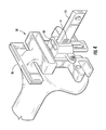
- FIGS. 2A-2E provide views of one preferred embodiment of a distal cut guide and components thereof for use in the invention.
- FIGS. 3A-3D provide views of one preferred embodiment of a femoral resection block for use in the invention.
- FIG. 4 shows one preferred embodiment of a distal cut guide mounted on an intramedullary rod according to the invention.
- FIG. 5 shows a distal view of one preferred embodiment of a distal cut guide mounted on an intramedullary rod according to the invention.
- FIG. 6 shows features of the distal cut guide that assist in visualizing the position of box cuts for a correspondingly size femoral knee implant.
- FIG. 7 shows a distal view of one preferred embodiment of a resection block mounted on an intramedullary rod according to the invention.
- the invention generally comprises a set of pinless resection instruments for preparing the distal femur for receipt of a femoral implant, along with methods of using the instruments.
- IM rod intramedullary rod 10
- the valgus rod 12 portion of the IM rod 10 has a narrow medial-lateral configuration.
- the narrow medial-lateral profile of the valgus rod 12 facilitates resection of the femur while the IM rod 10 is in the femur of the patient.
- a series of opposing grooves 14 are formed along the medial and lateral sides of the valgus rod 12 .
- the grooves 14 serve as locking positions for a distal cut guide 20 and a femoral resection block 70 , as will be described in further detail below.
- the medial and lateral sides of the valgus rod 12 are preferably flat, which provides additional engagement surface between the grooves 14 and a rod engagement member of the distal cut guide 20 and the femoral resection block 70 .
- the intramedullary stem portion 8 of the IM rod 10 is preferably provided with a plurality of lengthwise straight cutting flutes or splines 6 to prevent rotation of the IM rod 10 in the IM canal.
- a distal or training end of the stem 8 preferably has a tapered shoulder 4 formed thereon.
- the tapered shoulder 4 allows for a press fit fixation between the shoulder 4 and the IM canal, which further serves to maintain the IM rod 10 in a fixed, non-rotational relationship with the IM canal.
- the tapered shoulder 4 eliminates the use of fins on the stem portion 8 . As indicated in FIG.
- the valgus rod 12 is preferably set at a valgus angle (i.e., the axis of the valgus rod 12 is offset from the axis of the IM rod 10 ) in order to match the femoral resections to the mechanical axis of the patient's femur, in a manner known to those skilled in the art and described in U.S. Pat. No. 4,474,177, which is incorporated herein by reference.
- the valgus rod 12 will typically have a valgus angle of about 3 to about 7 degrees.
- An instrument set will typically include a set of rods 10 having various valgus angles, e.g. 3, 5 and 7 degrees, so that the surgeon can select the appropriate valgus angle for the particular patient.
- the surgeon lines up the valgus rod 12 with the trochlear groove of the femur.
- FIG. 2 provides views of a distal cut guide 20 for use in a pinless TKA procedure.
- the distal cut guide 20 is configured to mount on the valgus rod 12 portion of the IM rod 10 .
- the distal cut guide 20 includes a main body portion 22 , which generally supports and interconnects the other components of the distal cut guide 20 .
- the distal cut guide 20 is preferably provided with a stylus guide 24 having a stylus slot 25 passing therethrough.
- the stylus slot 25 can take various forms, but preferably has a lengthwise configuration to allow for visualization along the anterior surface of the femur, as shown in FIG. 2B .
- the bottom or posterior edge of the stylus slot 25 is preferably positioned to align with the anterior edge of the femoral resection block 70 , in order to assist the surgeon in visualizing the placement of the femoral resection block 70 .
- the distal cut guide 20 includes a distal resection guide 26 having a resection slot 27 .
- the distal resection guide 26 is configured for use in making a distal resection while the IM rod 10 is in the femur of the patient.
- the distal resection guide 26 is preferably provided with a pair of resection slots 27 , with each slot 27 opening along one of the opposing sides of the distal resection guide.
- Opposing walls of the distal resection guide 26 are joined by a central portion 29 .
- the central portion 29 is positioned to align with the valgus rod 12 when the distal cut guide 20 is mounted on the valgus rod 12 .
- the distal resection guide 26 may be attached to the stylus guide 24 or main body portion 22 via a distal resection guide support member 28 .
- the main body 22 of the distal cut guide 20 is provided with a pair of drill guides 30 .
- Each drill guide 30 has a drill aperture 31 therethrough.
- the drill apertures 31 are positioned to coincide with femoral pegs 39 on the femoral resection block 70 .
- the main body portion 22 of the distal cut guide 20 is configured for sliding engagement with an IM rod mount 40 .
- the main body portion 22 is configured to have two downwardly depending legs, with opposing rail members 34 positioned along an interior side of each leg.
- the IM rod mount 40 is configured to slide along the rail members 34 in the anterior-posterior orientation.
- a stop member 36 such as a set pin, can be positioned adjacent a posterior end of one or both rail members 34 .
- a lower surface of the stylus guide 24 prevents the IM rod mount 40 from disengaging anteriorly from the rail members 34 .
- a pair of posterior arms 38 can be provided on the main body portion 22 .
- the posterior arms 38 are preferably positioned and configured such that a flat posterior edge of each posterior arm 38 coincides with the anterior or upper edge of the posterior resection slot 75 P of the femoral resection block 70 .
- a pair of femoral pegs 39 can be provided on the proximal or leading face of the distal cut guide 20 .
- the femoral pegs 39 have a sharp, pointed configuration, which allows the pegs 39 to readily engage the distal surface of the uncut femur to assist in stabilizing the distal cut guide 20 on the valgus rod 12 .
- the femoral pegs 39 are sized such that they do not interfere with the distal cut.
- the IM rod mount 40 is slidingly engaged to the main body portion 22 , such that the main body portion 22 can be adjusted anteriorly-posteriorly relative to the valgus rod 12 .
- the IM rod mount 40 includes an IM rod aperture 41 .
- the IM rod aperture 41 is sized and configured to closely receive the valgus portion 12 of the IM rod 10 , so as to substantially prevent rotation or substantial movement of the IM rod mount 40 relative to the valgus rod 12 .
- a selective locking mechanism such as set screw 42 , is positioned for use in selectively fixing or locking the position of the IM rod mount 40 on the distal cut guide 20 . With the IM rod mount 40 locked to the main body portion 22 , the main body portion 22 can no longer translate relative to the valgus rod 12 .
- the IM rod mount 40 is configured to receive an IM rod engagement member 50 .
- the IM rod engagement member 50 is slidably engaged to IM rod mount 40 , such as via the engagement track or cavity 43 indicated in FIG. 2A . Details of a preferred embodiment of an IM rod engagement member 50 are shown in FIG. 2E .
- the IM rod engagement member 50 includes an IM rod aperture 51 generally formed by a pair of opposing rail members 52 .
- the IM rod aperture 51 is longer than the A-P dimension of the valgus rod 12 , such that the IM rod engagement member 50 can translate anteriorly-posteriorly along the valgus rod 12 .
- the IM rod engagement member 50 includes a stop means for selectively engaging the grooves 14 of the valgus rod 12 .
- the stop means is a pair of lengthwise IM rod detents 54 formed along anterior inner surfaces of the rail members 52 .
- Each IM rod detent 54 is configured to selectively engage a selected one of the grooves 14 of the valgus rod 12 .
- the distal cut guide 20 is selectively locked onto the valgus rod 12 by pushing or dropping the IM rod engagement member 50 down (posteriorly) until the IM rod detents 54 engage a selected pair of the opposing grooves 14 .
- the anterior portion of IM rod aperture 51 is configured to rest on the anterior surface of the valgus rod 12 . If the surgeon is not satisfied with the position of the distal cut guide 20 , the surgeon can disengage the distal cut guide 20 from the valgus rod 12 by pulling up on the IM rod engagement member 50 until the IM rod detents 54 disengage from the valgus rod 12 .
- a retaining means 55 is provided for use in retaining the IM rod engagement member 50 in the IM rod mount 40 .
- the retaining means 55 is a cutout 55 portion having opposing shoulders for engaging a retaining member 45 of the IM rod mount 40 .
- the configuration of the distal cut guide 20 shown in FIG. 2 allows a surgeon to size the femur, set rotation, set A-P positioning, make a distal resection, and drill peg holes with a single instrument.
- only one of the condyles (typically the medical condyle) will contact the proximal face of the distal cut guide 20 .
- the contact between the distal cut guide 20 and the condyle is used to stabilize the distal cut guide 20 .
- the surgeon preferably starts by cutting the distal condyle that is not touching the distal cut guide 20 . If the surgeon makes the initial cut on the condyle that is touching the distal cut guide 20 , this will leave a space between the cut condyle and the distal cut 20 , which will tend to destabilize the distal cut guide 20 .
- the instruments are provided in the form of a surgical kit, with the kit including a pair of distal cut guides 20 and matching femoral resection blocks 70 for each size of femoral implant (e.g. six sets of guides 20 and blocks 70 corresponding to implant sizes 1-6).
- the kit also preferably includes a set of femoral implants of various sizes (e.g. sizes 1-6), with the implants configured for implantation on the resections made by respectively sized resection blocks 70 .
- FIG. 3 provides views of a preferred embodiment of a femoral resection block 70 .
- the femoral resection block 70 has an IM rod aperture 71 for use in mounting the femoral resection block 70 on the valgus rod 12 .
- the femoral resection block 70 is provided with a means of locking or fixing the resection block 70 in a selected position on the valgus rod 12 .
- selective engagement is provided by an IM rod engagement member 90 that is disposed in a sliding relation to the resection block 70 .
- the IM engagement member 90 slides into an engagement track 77 formed in the resection block 70 . Details of one preferred embodiment of an IM rod engagement member 90 are shown in FIG.
- the engagement member 90 is provided with opposing rail members 92 , which form an IM rod slot 91 .
- the rail members 92 are held in a fixed relation to one another via an anterior cross bar 96 , a lower surface of which is configured to rest along tan anterior surface of the resection block 70 .
- a tab 98 preferably extends from the cross bar 96 for use by the surgeon in manipulating the IM rod engagement member 90 to engage or disengage the valgus rod 12 .
- each IM rod detent 94 is provided along inner surfaces of the rail members 92 . Like the detents 54 of the distal resection guide 20 , each IM rod detent 94 is configured to selectively engage a selected one of the grooves 14 of the valgus rod 12 . In the embodiment shown in FIG. 3 , the resection guide 70 is selectively locked onto the valgus rod 12 by pushing or dropping the IM rod engagement member 90 down (posteriorly) until the IM rod detents 94 engage a selected pair of the opposing grooves 14 .
- the IM rod engagement member 90 can be provided with a retaining means 95 , such as the retaining foot 95 formed on a lower end of a rail member 92 , as shown in FIG. 3D .
- a retaining means 81 such as a set screw or plugs 81 , can be provided on the body of the resection block 70 for use in retaining the IM rod engagement member 90 in the resection block 70 .
- Femoral pegs 73 are provided on a posterior or leading surface of the resection block 70 .
- the femoral pegs 73 are sized and positioned to coincide with the drill apertures 31 of the drill guides 30 , such that the pegs 73 can be inserted in holes drilled into the distal cut femur via the drill apertures 31 .
- the femoral resection block has an anterior resection slot 75 A, a posterior resection slot 75 P, an anterior chamfer resection block 75 AC, and a posterior chamfer reselection slot 75 PC. All of the resections slots are preferably broken into two slots, so as to facilitate resectioning around the valgus rod 12 . All of the reselection slots preferably open along respective lateral edges of the block 70 .
- One or more posterior positioning members 76 preferably extend from a posterior edge of the femoral resection block 70 .
- the posterior positioning members 76 are sized to match the posterior edge of the femoral implant, in order to assist the surgeon in visualizing final positioning of the implant.
- the engagement portion of the instruments has been described as having a negative engagement (i.e. grooves 14 ) on the valgus rod 12 and a positive engagement member (e.g. detent 54 ) on the corresponding IM rod engagement member 50 , 90 , it will be appreciated that the engagements could be reversed without departing from the spirit and scope of the invention.
- a positive engagement such as a series of detents, could be provided on the valgus rod 12 and a negative engagement, such as grooves, could be provided on the rod engagement member 50 , 90 .
- pin holes 79 are preferably provided on the femoral resection block 70 . As shown in FIG. 3B , the pin holes 79 are preferably located on the medial and lateral sides of the resection block 70 , such that the pin holes 79 are positioned over cortical bone.
- the components of the kit are preferably arranged in a convenient format, such as in a surgical tray or case.
- the kit components do not have to be packaged or delivered together, provided that they are assembled or collected together in the operating room for use at the time of surgery.
- the size of the femur is preferably approximated through pre-operative x-ray templating.
- the pinless instruments of the invention are designed to allow for femoral sizing without the use of stylus. Sizing is performed by visually aligning the top and bottom of the distal resection guide 20 with the anterior cortex and posterior condyles, respectively.
- a rongeur is preferably used early in the procedure to create a small notch 100 at the deepest point of the anterior trochlear groove. The base of the notch should be flush with the anterior cortex.
- the surgeon drills an opening in the femoral canal for insertion of the IM rod 10 , in a manner known to those of skill in the art.
- the hole is either placed medial and anterior to the anteromedial corner of the intercondylar notch, or in the center of the trochlear groove.
- the valgus rod 12 sets the valgus angled (typically 5°), as well as the external rotation of the resection guide 20 .
- the distal resection guide 20 is preferably loaded onto the valgus rod 12 portion of the IM rod 10 , and is locked into position by pushing down the locking shim or IM rod engagement member 50 .
- the IM rod 10 with the attached resection guide 20 is then inserted into the femoral canal.
- the surgeon irrigates and aspirates several times to reduce the chance of a fat embolus, in a manner well known to those of skill in the art.
- the resection guide 20 should be aligned with the trochlear groove (A/P axis or Whiteside's line), as indicated in FIG. 5 .
- the epicondyles and posterior condyles can be used as a secondary check for femoral rotation.
- the rod 10 is secured in the femoral canal by impacting until the expanded fluted portion of the rod is flush with the surface of the distal femur.
- the surgeon unlocks the distal resection guide 20 and repositions the distal resection guide 20 gently against the distal femur.
- the surgeon reengages the IM rod engagement member 50 in order to lock the guide 20 in position on the valgus rod 12 .
- the resection guide 20 locking/set screw 42 is loosened to allow the guide 20 to be adjusted anterior/posterior (A/P).
- the surgeon sets the A/P position of the 4-in-1 resection guide peg holes by initially aligning the anterior window or stylus slot 25 of the guide 20 with the anterior cortex of the distal femur.
- Alignment with the anterior cortex is preferably achieved by looking through the stylus slot 25 at the rongeur notch 100 that was previously made on the anterior trochlear groove, as indicated in FIG. 5 .
- a smooth Steinmann pin (4.88 mm) may be optionally inserted through the window 25 into a notch 100 to act as a stylus.
- approximately 10 mm and 8 mm of posterior condyle should be visible below the medial and lateral posterior feet or arms 38 , respectively. As shown in FIG.
- the surface of the bottom edge of the anterior window/stylus slot 25 and the bottom surface of the posterior feet 38 represent the internal geometry of the correspondingly sized femoral component. This feature allows the surgeon to readily visualize the location of the anterior and posterior resections. If the surgeon determines that too much or too little posterior condyle will be resected, the A/P position of the cutting guide 20 can be adjusted or the resection guide 20 can be removed and replaced with a different size resection guide 20 . To further assist in confirming sizing, the medial/lateral width of the guide 20 is preferably the same width as that of the corresponding size femoral component, as indicated in FIG. 5 .
- the locking screw 42 is tightened to set the A/P position of the guide 20 , and particularly the location of the drill apertures 31 , since the apertures 31 will establish the location of the femoral resection block 70 .
- the rod 10 is then impacted into the femur until the femoral pins 39 are fully seated in the most prominent distal condyle.
- the surgeon then drills through both of the drill apertures 31 to create holes for the femoral resection block 70 .
- the distal resection is carried out using the distal resection slot 27 .
- the most prominent distal condyle provides stability and therefore should be resected last.
- the guide 20 is unlocked and removed from the valgus rod 12 .
- the surgeon selects a femoral resection block 70 that corresponds in size to the distal resection guide 20 .
- the resection block 70 is slid down the valgus rod 12 until the resection block 70 pegs 73 sink into the peg holes and the block 70 contacts the resected distal femur.
- the resection block 70 is locked to the rod by pressing down on the road engagement member 90 . If further distal contact is desired, the rod 10 can be impacted more deeply into the femur.
- the instruments are design for pinless TKA procedures, pins can optionally be driven into the pin holes 79 of the block 70 if added stability is desired.
- the distance between the posterior resection slot 75 P and the posterior edge of the positioning member 76 of the block 70 matches the thickness of the posterior condyle of the corresponding femoral component, as indicated in FIG. 7 .
- the rod 10 is left in the femur during the box and chamfer resections. Once resections are complete, the rod 10 is removed from the patient.
- the surgical technique concludes with trochlear groove resection, tibial resection and patellar procedures, in a manner known to those of skill in the art.
- the tibial resection can be made prior to the femoral resection, at the discretion of the surgeon.
Landscapes
- Health & Medical Sciences (AREA)
- Surgery (AREA)
- Life Sciences & Earth Sciences (AREA)
- Orthopedic Medicine & Surgery (AREA)
- Molecular Biology (AREA)
- Public Health (AREA)
- Engineering & Computer Science (AREA)
- Biomedical Technology (AREA)
- Heart & Thoracic Surgery (AREA)
- Medical Informatics (AREA)
- Veterinary Medicine (AREA)
- Animal Behavior & Ethology (AREA)
- General Health & Medical Sciences (AREA)
- Nuclear Medicine, Radiotherapy & Molecular Imaging (AREA)
- Dentistry (AREA)
- Oral & Maxillofacial Surgery (AREA)
- Neurology (AREA)
- Physical Education & Sports Medicine (AREA)
- Transplantation (AREA)
- Surgical Instruments (AREA)
- Prostheses (AREA)
Abstract
Description
Claims (16)
Priority Applications (2)
| Application Number | Priority Date | Filing Date | Title |
|---|---|---|---|
| US11/684,395 US8702714B2 (en) | 2006-03-09 | 2007-03-09 | Instruments for total knee arthroplasty |
| US14/206,751 US9308006B2 (en) | 2006-03-09 | 2014-03-12 | Instruments for total knee arthroplasty |
Applications Claiming Priority (2)
| Application Number | Priority Date | Filing Date | Title |
|---|---|---|---|
| US78063506P | 2006-03-09 | 2006-03-09 | |
| US11/684,395 US8702714B2 (en) | 2006-03-09 | 2007-03-09 | Instruments for total knee arthroplasty |
Related Child Applications (1)
| Application Number | Title | Priority Date | Filing Date |
|---|---|---|---|
| US14/206,751 Continuation US9308006B2 (en) | 2006-03-09 | 2014-03-12 | Instruments for total knee arthroplasty |
Publications (2)
| Publication Number | Publication Date |
|---|---|
| US20070213738A1 US20070213738A1 (en) | 2007-09-13 |
| US8702714B2 true US8702714B2 (en) | 2014-04-22 |
Family
ID=38479917
Family Applications (2)
| Application Number | Title | Priority Date | Filing Date |
|---|---|---|---|
| US11/684,395 Expired - Fee Related US8702714B2 (en) | 2006-03-09 | 2007-03-09 | Instruments for total knee arthroplasty |
| US14/206,751 Active 2027-10-11 US9308006B2 (en) | 2006-03-09 | 2014-03-12 | Instruments for total knee arthroplasty |
Family Applications After (1)
| Application Number | Title | Priority Date | Filing Date |
|---|---|---|---|
| US14/206,751 Active 2027-10-11 US9308006B2 (en) | 2006-03-09 | 2014-03-12 | Instruments for total knee arthroplasty |
Country Status (1)
| Country | Link |
|---|---|
| US (2) | US8702714B2 (en) |
Cited By (3)
| Publication number | Priority date | Publication date | Assignee | Title |
|---|---|---|---|---|
| US20130325045A1 (en) * | 2012-06-04 | 2013-12-05 | Depuy International Limited | Surgical cutting guide |
| US10070868B2 (en) | 2013-08-02 | 2018-09-11 | Zimmer, Inc. | Resection shift guide and method |
| US10905445B2 (en) | 2017-05-11 | 2021-02-02 | Zimmer Gmbh | Adjustable cutting block for knee arthroplasty |
Families Citing this family (66)
| Publication number | Priority date | Publication date | Assignee | Title |
|---|---|---|---|---|
| US8801720B2 (en) | 2002-05-15 | 2014-08-12 | Otismed Corporation | Total joint arthroplasty system |
| US9808262B2 (en) | 2006-02-15 | 2017-11-07 | Howmedica Osteonics Corporation | Arthroplasty devices and related methods |
| WO2007097853A2 (en) | 2006-02-15 | 2007-08-30 | Otismed Corp | Arthroplasty jigs and related methods |
| US8702714B2 (en) * | 2006-03-09 | 2014-04-22 | Microsoft Orthopedics Holdings Inc. | Instruments for total knee arthroplasty |
| US8460302B2 (en) | 2006-12-18 | 2013-06-11 | Otismed Corporation | Arthroplasty devices and related methods |
| GB2447702A (en) | 2007-03-23 | 2008-09-24 | Univ Leeds | Surgical bone cutting template |
| US8265949B2 (en) | 2007-09-27 | 2012-09-11 | Depuy Products, Inc. | Customized patient surgical plan |
| US8357111B2 (en) | 2007-09-30 | 2013-01-22 | Depuy Products, Inc. | Method and system for designing patient-specific orthopaedic surgical instruments |
| US9138239B2 (en) | 2007-09-30 | 2015-09-22 | DePuy Synthes Products, Inc. | Customized patient-specific tibial cutting blocks |
| ES2838598T3 (en) | 2007-09-30 | 2021-07-02 | Depuy Products Inc | Customized, patient-specific orthopedic surgical instrument |
| US9173662B2 (en) | 2007-09-30 | 2015-11-03 | DePuy Synthes Products, Inc. | Customized patient-specific tibial cutting blocks |
| US8460303B2 (en) | 2007-10-25 | 2013-06-11 | Otismed Corporation | Arthroplasty systems and devices, and related methods |
| USD642263S1 (en) | 2007-10-25 | 2011-07-26 | Otismed Corporation | Arthroplasty jig blank |
| US10582934B2 (en) | 2007-11-27 | 2020-03-10 | Howmedica Osteonics Corporation | Generating MRI images usable for the creation of 3D bone models employed to make customized arthroplasty jigs |
| US8221430B2 (en) | 2007-12-18 | 2012-07-17 | Otismed Corporation | System and method for manufacturing arthroplasty jigs |
| US8545509B2 (en) | 2007-12-18 | 2013-10-01 | Otismed Corporation | Arthroplasty system and related methods |
| US8777875B2 (en) | 2008-07-23 | 2014-07-15 | Otismed Corporation | System and method for manufacturing arthroplasty jigs having improved mating accuracy |
| US8737700B2 (en) | 2007-12-18 | 2014-05-27 | Otismed Corporation | Preoperatively planning an arthroplasty procedure and generating a corresponding patient specific arthroplasty resection guide |
| US8617171B2 (en) | 2007-12-18 | 2013-12-31 | Otismed Corporation | Preoperatively planning an arthroplasty procedure and generating a corresponding patient specific arthroplasty resection guide |
| US8480679B2 (en) | 2008-04-29 | 2013-07-09 | Otismed Corporation | Generation of a computerized bone model representative of a pre-degenerated state and useable in the design and manufacture of arthroplasty devices |
| US8160345B2 (en) | 2008-04-30 | 2012-04-17 | Otismed Corporation | System and method for image segmentation in generating computer models of a joint to undergo arthroplasty |
| US8311306B2 (en) | 2008-04-30 | 2012-11-13 | Otismed Corporation | System and method for image segmentation in generating computer models of a joint to undergo arthroplasty |
| US8715291B2 (en) | 2007-12-18 | 2014-05-06 | Otismed Corporation | Arthroplasty system and related methods |
| US9408618B2 (en) | 2008-02-29 | 2016-08-09 | Howmedica Osteonics Corporation | Total hip replacement surgical guide tool |
| US8226658B2 (en) * | 2008-05-09 | 2012-07-24 | Depuy Products, Inc. | Instrument for guiding resection of a greater tubercle |
| US8617175B2 (en) | 2008-12-16 | 2013-12-31 | Otismed Corporation | Unicompartmental customized arthroplasty cutting jigs and methods of making the same |
| JP5302595B2 (en) * | 2008-08-06 | 2013-10-02 | 株式会社日立ハイテクノロジーズ | Inclination observation method and observation apparatus |
| EP2538864B1 (en) | 2010-02-25 | 2018-10-31 | DePuy Products, Inc. | Customized patient-specific bone cutting blocks |
| WO2011106407A1 (en) | 2010-02-25 | 2011-09-01 | Depuy Products, Inc. | Method of fabricating customized patient-specific bone cutting blocks |
| EP2538853A4 (en) | 2010-02-25 | 2016-07-27 | Depuy Products Inc | Customized patient-specific bone cutting blocks |
| US8641721B2 (en) | 2011-06-30 | 2014-02-04 | DePuy Synthes Products, LLC | Customized patient-specific orthopaedic pin guides |
| US9204897B2 (en) | 2011-12-19 | 2015-12-08 | Zimmer, Inc. | Surgical cutting guide |
| US8808298B2 (en) * | 2012-05-18 | 2014-08-19 | Zimmer, Inc. | Pivoting cut guides |
| US9402637B2 (en) | 2012-10-11 | 2016-08-02 | Howmedica Osteonics Corporation | Customized arthroplasty cutting guides and surgical methods using the same |
| WO2014107716A1 (en) | 2013-01-07 | 2014-07-10 | Jones Nolan C | Distal resection systems and methods |
| US10022130B2 (en) * | 2013-03-05 | 2018-07-17 | Depuy Ireland Unlimited Company | Polymer 4-in-1 femoral cutting block |
| US10111673B2 (en) * | 2013-03-05 | 2018-10-30 | Depuy Ireland Unlimited Company | Polymer 4-in-1 femoral cutting block including metallic protective bushings |
| CN104095664B (en) | 2013-04-12 | 2016-12-28 | 德普伊(爱尔兰)公司 | Distal femur clamp assembly and the distal femur cutting device with this assembly |
| US20160015426A1 (en) | 2014-07-15 | 2016-01-21 | Treace Medical Concepts, Inc. | Bone positioning and cutting system and method |
| US9687250B2 (en) | 2015-01-07 | 2017-06-27 | Treace Medical Concepts, Inc. | Bone cutting guide systems and methods |
| US10849631B2 (en) | 2015-02-18 | 2020-12-01 | Treace Medical Concepts, Inc. | Pivotable bone cutting guide useful for bone realignment and compression techniques |
| US10653467B2 (en) | 2015-05-06 | 2020-05-19 | Treace Medical Concepts, Inc. | Intra-osseous plate system and method |
| US10849663B2 (en) | 2015-07-14 | 2020-12-01 | Treace Medical Concepts, Inc. | Bone cutting guide systems and methods |
| US9622805B2 (en) | 2015-08-14 | 2017-04-18 | Treace Medical Concepts, Inc. | Bone positioning and preparing guide systems and methods |
| JP6985248B2 (en) | 2015-07-14 | 2021-12-22 | トリース メディカル コンセプツ,インコーポレイティド | Bone positioning guide |
| WO2017031020A1 (en) | 2015-08-14 | 2017-02-23 | Treace Medical Concepts, Inc. | Tarsal-metatarsal joint procedure utilizing fulcrum |
| US11278337B2 (en) | 2015-08-14 | 2022-03-22 | Treace Medical Concepts, Inc. | Tarsal-metatarsal joint procedure utilizing fulcrum |
| US10575862B2 (en) | 2015-09-18 | 2020-03-03 | Treace Medical Concepts, Inc. | Joint spacer systems and methods |
| US10512470B1 (en) | 2016-08-26 | 2019-12-24 | Treace Medical Concepts, Inc. | Osteotomy procedure for correcting bone misalignment |
| US10524808B1 (en) | 2016-11-11 | 2020-01-07 | Treace Medical Concepts, Inc. | Devices and techniques for performing an osteotomy procedure on a first metatarsal to correct a bone misalignment |
| AU201711075S (en) * | 2017-02-22 | 2017-03-06 | Orthopaedic surgery cutting block guide | |
| US10939939B1 (en) | 2017-02-26 | 2021-03-09 | Treace Medical Concepts, Inc. | Fulcrum for tarsal-metatarsal joint procedure |
| US11051829B2 (en) | 2018-06-26 | 2021-07-06 | DePuy Synthes Products, Inc. | Customized patient-specific orthopaedic surgical instrument |
| JP2021531857A (en) | 2018-07-11 | 2021-11-25 | トリース メディカル コンセプツ,インコーポレイティド | Compression stretcher for angled and rearranged bones |
| WO2020014660A1 (en) | 2018-07-12 | 2020-01-16 | Treace Medical Concepts, Inc. | Multi-diameter bone pin for installing and aligning bone fixation plate while minimizing bone damage |
| US11607250B2 (en) | 2019-02-13 | 2023-03-21 | Treace Medical Concepts, Inc. | Tarsal-metatarsal joint procedure utilizing compressor-distractor and instrument providing sliding surface |
| US11627954B2 (en) | 2019-08-07 | 2023-04-18 | Treace Medical Concepts, Inc. | Bi-planar instrument for bone cutting and joint realignment procedure |
| US11889998B1 (en) | 2019-09-12 | 2024-02-06 | Treace Medical Concepts, Inc. | Surgical pin positioning lock |
| US11931106B2 (en) | 2019-09-13 | 2024-03-19 | Treace Medical Concepts, Inc. | Patient-specific surgical methods and instrumentation |
| US11890039B1 (en) | 2019-09-13 | 2024-02-06 | Treace Medical Concepts, Inc. | Multi-diameter K-wire for orthopedic applications |
| US11986251B2 (en) | 2019-09-13 | 2024-05-21 | Treace Medical Concepts, Inc. | Patient-specific osteotomy instrumentation |
| AU2021212261A1 (en) | 2020-01-31 | 2022-08-18 | Treace Medical Concepts, Inc. | Metatarsophalangeal joint preparation and metatarsal realignment for fusion |
| CA3114820C (en) * | 2020-04-16 | 2023-10-03 | Orthosoft Ulc | Devices and methods for posterior resection in robotically assisted partial knee arthroplasties |
| WO2021236838A1 (en) | 2020-05-19 | 2021-11-25 | Treace Medical Concepts, Inc. | Devices and techniques for treating metatarsus adductus |
| USD1011524S1 (en) | 2022-02-23 | 2024-01-16 | Treace Medical Concepts, Inc. | Compressor-distractor for the foot |
| US12076025B2 (en) | 2022-05-11 | 2024-09-03 | DePuy Synthes Products, Inc. | Polymer cutting block |
Citations (12)
| Publication number | Priority date | Publication date | Assignee | Title |
|---|---|---|---|---|
| US3757705A (en) * | 1972-01-05 | 1973-09-11 | L Maslow | Adjustable shelving |
| US4474177A (en) * | 1983-03-09 | 1984-10-02 | Wright Manufacturing Company | Method and apparatus for shaping a distal femoral surface |
| US4952213A (en) * | 1989-02-03 | 1990-08-28 | Boehringer Mannheim Corporation | Tibial cutting guide |
| US5002545A (en) * | 1989-01-30 | 1991-03-26 | Dow Corning Wright Corporation | Tibial surface shaping guide for knee implants |
| US5047032A (en) * | 1987-10-21 | 1991-09-10 | Richards Medical Company | Method and apparatus for cutting joint surfaces |
| US5342367A (en) * | 1992-02-20 | 1994-08-30 | Wright Medical Technology, Inc. | Rotationally and angularly adjustable tibial cutting guide and method of use |
| US5417694A (en) * | 1993-11-08 | 1995-05-23 | Smith & Nephew Richards Inc. | Distal femoral cutting guide apparatus with anterior or posterior referencing for use in knee joint replacement surgery |
| US5474559A (en) * | 1993-07-06 | 1995-12-12 | Zimmer, Inc. | Femoral milling instrumentation for use in total knee arthroplasty with optional cutting guide attachment |
| US5611802A (en) * | 1995-02-14 | 1997-03-18 | Samuelson; Kent M. | Method and apparatus for resecting bone |
| US5649928A (en) * | 1994-07-08 | 1997-07-22 | Eska Medical Gmbh & Co. | Device for determining resection surfaces of femur and tibia in preparation for implantation of total knee endoprosthesis |
| US5662656A (en) * | 1995-12-08 | 1997-09-02 | Wright Medical Technology, Inc. | Instrumentation and method for distal femoral sizing, and anterior and distal femoral resections |
| US5683397A (en) * | 1995-02-15 | 1997-11-04 | Smith & Nephew, Inc. | Distal femoral cutting guide apparatus for use in knee joint replacement surgery |
Family Cites Families (13)
| Publication number | Priority date | Publication date | Assignee | Title |
|---|---|---|---|---|
| US5681316A (en) * | 1996-08-22 | 1997-10-28 | Johnson & Johnson Professional, Inc. | Tibial resection guide |
| US5830216A (en) * | 1996-10-30 | 1998-11-03 | Bristol-Myers Squibb Company | Apparatus and method for knee implantation |
| US6090114A (en) * | 1997-02-10 | 2000-07-18 | Stryker Howmedica Osteonics Corp. | Tibial plateau resection guide |
| US6013081A (en) * | 1998-09-09 | 2000-01-11 | Sulzer Orthopedics Inc. | Apparatus and method for anterior and posterior referenced sizing and distal femur resection |
| US7029477B2 (en) * | 2002-12-20 | 2006-04-18 | Zimmer Technology, Inc. | Surgical instrument and positioning method |
| US8043294B2 (en) | 2004-03-05 | 2011-10-25 | Wright Medical Technology, Inc. | Reference mark adjustment mechanism for a femoral caliper and method of using the same |
| US8317797B2 (en) * | 2005-02-08 | 2012-11-27 | Rasmussen G Lynn | Arthroplasty systems and methods for optimally aligning and tensioning a knee prosthesis |
| US8734453B2 (en) | 2005-02-21 | 2014-05-27 | Wright Medical Technology, Inc. | Instruments for minimally invasive surgery total knee arthroplasty |
| US20070149977A1 (en) * | 2005-11-28 | 2007-06-28 | Zimmer Technology, Inc. | Surgical component positioner |
| US8702714B2 (en) * | 2006-03-09 | 2014-04-22 | Microsoft Orthopedics Holdings Inc. | Instruments for total knee arthroplasty |
| US7959637B2 (en) * | 2007-03-13 | 2011-06-14 | Biomet Manufacturing Corp. | Distal femoral cutting guide |
| US8162949B2 (en) * | 2008-04-21 | 2012-04-24 | Biomet Manufacturing Corp. | Tibial resection guide |
| US8403935B2 (en) * | 2009-11-10 | 2013-03-26 | Wright Medical Technology, Inc. | Adjustable revision guide |
-
2007
- 2007-03-09 US US11/684,395 patent/US8702714B2/en not_active Expired - Fee Related
-
2014
- 2014-03-12 US US14/206,751 patent/US9308006B2/en active Active
Patent Citations (12)
| Publication number | Priority date | Publication date | Assignee | Title |
|---|---|---|---|---|
| US3757705A (en) * | 1972-01-05 | 1973-09-11 | L Maslow | Adjustable shelving |
| US4474177A (en) * | 1983-03-09 | 1984-10-02 | Wright Manufacturing Company | Method and apparatus for shaping a distal femoral surface |
| US5047032A (en) * | 1987-10-21 | 1991-09-10 | Richards Medical Company | Method and apparatus for cutting joint surfaces |
| US5002545A (en) * | 1989-01-30 | 1991-03-26 | Dow Corning Wright Corporation | Tibial surface shaping guide for knee implants |
| US4952213A (en) * | 1989-02-03 | 1990-08-28 | Boehringer Mannheim Corporation | Tibial cutting guide |
| US5342367A (en) * | 1992-02-20 | 1994-08-30 | Wright Medical Technology, Inc. | Rotationally and angularly adjustable tibial cutting guide and method of use |
| US5474559A (en) * | 1993-07-06 | 1995-12-12 | Zimmer, Inc. | Femoral milling instrumentation for use in total knee arthroplasty with optional cutting guide attachment |
| US5417694A (en) * | 1993-11-08 | 1995-05-23 | Smith & Nephew Richards Inc. | Distal femoral cutting guide apparatus with anterior or posterior referencing for use in knee joint replacement surgery |
| US5649928A (en) * | 1994-07-08 | 1997-07-22 | Eska Medical Gmbh & Co. | Device for determining resection surfaces of femur and tibia in preparation for implantation of total knee endoprosthesis |
| US5611802A (en) * | 1995-02-14 | 1997-03-18 | Samuelson; Kent M. | Method and apparatus for resecting bone |
| US5683397A (en) * | 1995-02-15 | 1997-11-04 | Smith & Nephew, Inc. | Distal femoral cutting guide apparatus for use in knee joint replacement surgery |
| US5662656A (en) * | 1995-12-08 | 1997-09-02 | Wright Medical Technology, Inc. | Instrumentation and method for distal femoral sizing, and anterior and distal femoral resections |
Cited By (5)
| Publication number | Priority date | Publication date | Assignee | Title |
|---|---|---|---|---|
| US20130325045A1 (en) * | 2012-06-04 | 2013-12-05 | Depuy International Limited | Surgical cutting guide |
| US9033989B2 (en) * | 2012-06-04 | 2015-05-19 | Depuy (Ireland) | Surgical cutting guide |
| US10070868B2 (en) | 2013-08-02 | 2018-09-11 | Zimmer, Inc. | Resection shift guide and method |
| US10905445B2 (en) | 2017-05-11 | 2021-02-02 | Zimmer Gmbh | Adjustable cutting block for knee arthroplasty |
| US11484326B2 (en) | 2017-05-11 | 2022-11-01 | Zimmer Gmbh | Adjustable cutting block for knee arthroplasty |
Also Published As
| Publication number | Publication date |
|---|---|
| US20070213738A1 (en) | 2007-09-13 |
| US9308006B2 (en) | 2016-04-12 |
| US20140194884A1 (en) | 2014-07-10 |
Similar Documents
| Publication | Publication Date | Title |
|---|---|---|
| US8702714B2 (en) | Instruments for total knee arthroplasty | |
| US20210259715A1 (en) | Orthopaedic surgical instrumentation for performing a patellofemoral arthroplasty procedure | |
| AU2016210631B2 (en) | Bi-cruciate knee system | |
| US9149287B2 (en) | Femoral cut guide | |
| EP2623045B1 (en) | Surgical instrumentation set | |
| US8870883B2 (en) | Method for less invasive knee resection | |
| US7789885B2 (en) | Instrumentation for knee resection | |
| US8551100B2 (en) | Instrumentation for knee resection | |
| US20220192686A1 (en) | Resection guides, sweeping reamers, and methods for use in total ankle replacement | |
| US20140066934A1 (en) | Bi-Cruciate Knee System | |
| EP3265033B1 (en) | Bi-cruciate knee system | |
| US20150173781A1 (en) | Bi-cruciate knee system | |
| US11771442B2 (en) | Bi-cruciate knee system |
Legal Events
| Date | Code | Title | Description |
|---|---|---|---|
| AS | Assignment |
Owner name: WRIGHT MEDICAL TECHNOLOGY, INC., TENNESSEE Free format text: ASSIGNMENT OF ASSIGNORS INTEREST;ASSIGNORS:MARTIN, JEFFREY W.;WONG, KEVIN;HARRIS, BRIAN R., JR.;SIGNING DATES FROM 20070502 TO 20070504;REEL/FRAME:019266/0219 Owner name: WRIGHT MEDICAL TECHNOLOGY, INC., TENNESSEE Free format text: ASSIGNMENT OF ASSIGNORS INTEREST;ASSIGNORS:MARTIN, JEFFREY W.;WONG, KEVIN;HARRIS, BRIAN R., JR.;REEL/FRAME:019266/0219;SIGNING DATES FROM 20070502 TO 20070504 |
|
| AS | Assignment |
Owner name: OTSUKA MEDICAL DEVICES CO., LTD., JAPAN Free format text: PATENT SECURITY AGREEMENT SUPPLEMENT;ASSIGNOR:MICROPORT ORTHOPEDICS HOLDINGS INC.;REEL/FRAME:031968/0377 Effective date: 20140108 |
|
| AS | Assignment |
Owner name: MICROPORT ORTHOPEDICS HOLDINGS INC., NETHERLANDS Free format text: ASSIGNMENT OF ASSIGNORS INTEREST;ASSIGNOR:WRIGHT MEDICAL TECHNOLOGY, INC.;REEL/FRAME:032348/0275 Effective date: 20140106 |
|
| AS | Assignment |
Owner name: MICROPORT ORTHOPEDICS HOLDINGS INC., NETHERLANDS Free format text: ASSIGNMENT OF ASSIGNORS INTEREST;ASSIGNOR:WRIGHT MEDICAL TECHNOLOGY, INC.;REEL/FRAME:032410/0254 Effective date: 20140106 |
|
| STCF | Information on status: patent grant |
Free format text: PATENTED CASE |
|
| CC | Certificate of correction | ||
| MAFP | Maintenance fee payment |
Free format text: PAYMENT OF MAINTENANCE FEE, 4TH YEAR, LARGE ENTITY (ORIGINAL EVENT CODE: M1551) Year of fee payment: 4 |
|
| AS | Assignment |
Owner name: MICROPORT ORTHOPEDICS HOLDINGS INC., TENNESSEE Free format text: RELEASE BY SECURED PARTY;ASSIGNOR:OTSUKA MEDICAL DEVICES CO., LTD.;REEL/FRAME:044772/0708 Effective date: 20170810 |
|
| FEPP | Fee payment procedure |
Free format text: MAINTENANCE FEE REMINDER MAILED (ORIGINAL EVENT CODE: REM.); ENTITY STATUS OF PATENT OWNER: LARGE ENTITY |
|
| LAPS | Lapse for failure to pay maintenance fees |
Free format text: PATENT EXPIRED FOR FAILURE TO PAY MAINTENANCE FEES (ORIGINAL EVENT CODE: EXP.); ENTITY STATUS OF PATENT OWNER: LARGE ENTITY |
|
| STCH | Information on status: patent discontinuation |
Free format text: PATENT EXPIRED DUE TO NONPAYMENT OF MAINTENANCE FEES UNDER 37 CFR 1.362 |
|
| FP | Lapsed due to failure to pay maintenance fee |
Effective date: 20220422 |