US8777875B2 - System and method for manufacturing arthroplasty jigs having improved mating accuracy - Google Patents
System and method for manufacturing arthroplasty jigs having improved mating accuracy Download PDFInfo
- Publication number
- US8777875B2 US8777875B2 US12/505,056 US50505609A US8777875B2 US 8777875 B2 US8777875 B2 US 8777875B2 US 50505609 A US50505609 A US 50505609A US 8777875 B2 US8777875 B2 US 8777875B2
- Authority
- US
- United States
- Prior art keywords
- jig
- contour line
- tibia
- contour
- model
- Prior art date
- Legal status (The legal status is an assumption and is not a legal conclusion. Google has not performed a legal analysis and makes no representation as to the accuracy of the status listed.)
- Active, expires
Links
Images


Classifications
-
- A—HUMAN NECESSITIES
- A61—MEDICAL OR VETERINARY SCIENCE; HYGIENE
- A61B—DIAGNOSIS; SURGERY; IDENTIFICATION
- A61B34/00—Computer-aided surgery; Manipulators or robots specially adapted for use in surgery
- A61B34/10—Computer-aided planning, simulation or modelling of surgical operations
-
- A—HUMAN NECESSITIES
- A61—MEDICAL OR VETERINARY SCIENCE; HYGIENE
- A61B—DIAGNOSIS; SURGERY; IDENTIFICATION
- A61B17/00—Surgical instruments, devices or methods, e.g. tourniquets
- A61B17/14—Surgical saws ; Accessories therefor
- A61B17/15—Guides therefor
-
- A—HUMAN NECESSITIES
- A61—MEDICAL OR VETERINARY SCIENCE; HYGIENE
- A61B—DIAGNOSIS; SURGERY; IDENTIFICATION
- A61B17/00—Surgical instruments, devices or methods, e.g. tourniquets
- A61B17/14—Surgical saws ; Accessories therefor
- A61B17/15—Guides therefor
- A61B17/154—Guides therefor for preparing bone for knee prosthesis
- A61B17/155—Cutting femur
-
- A—HUMAN NECESSITIES
- A61—MEDICAL OR VETERINARY SCIENCE; HYGIENE
- A61B—DIAGNOSIS; SURGERY; IDENTIFICATION
- A61B17/00—Surgical instruments, devices or methods, e.g. tourniquets
- A61B17/14—Surgical saws ; Accessories therefor
- A61B17/15—Guides therefor
- A61B17/154—Guides therefor for preparing bone for knee prosthesis
- A61B17/157—Cutting tibia
-
- A—HUMAN NECESSITIES
- A61—MEDICAL OR VETERINARY SCIENCE; HYGIENE
- A61B—DIAGNOSIS; SURGERY; IDENTIFICATION
- A61B17/00—Surgical instruments, devices or methods, e.g. tourniquets
- A61B17/16—Bone cutting, breaking or removal means other than saws, e.g. Osteoclasts; Drills or chisels for bones; Trepans
- A61B17/1662—Bone cutting, breaking or removal means other than saws, e.g. Osteoclasts; Drills or chisels for bones; Trepans for particular parts of the body
- A61B17/1675—Bone cutting, breaking or removal means other than saws, e.g. Osteoclasts; Drills or chisels for bones; Trepans for particular parts of the body for the knee
-
- A—HUMAN NECESSITIES
- A61—MEDICAL OR VETERINARY SCIENCE; HYGIENE
- A61B—DIAGNOSIS; SURGERY; IDENTIFICATION
- A61B17/00—Surgical instruments, devices or methods, e.g. tourniquets
- A61B17/16—Bone cutting, breaking or removal means other than saws, e.g. Osteoclasts; Drills or chisels for bones; Trepans
- A61B17/17—Guides or aligning means for drills, mills, pins or wires
- A61B17/1739—Guides or aligning means for drills, mills, pins or wires specially adapted for particular parts of the body
- A61B17/1764—Guides or aligning means for drills, mills, pins or wires specially adapted for particular parts of the body for the knee
-
- A—HUMAN NECESSITIES
- A61—MEDICAL OR VETERINARY SCIENCE; HYGIENE
- A61B—DIAGNOSIS; SURGERY; IDENTIFICATION
- A61B17/00—Surgical instruments, devices or methods, e.g. tourniquets
- A61B17/56—Surgical instruments or methods for treatment of bones or joints; Devices specially adapted therefor
- A61B17/58—Surgical instruments or methods for treatment of bones or joints; Devices specially adapted therefor for osteosynthesis, e.g. bone plates, screws, setting implements or the like
-
- A—HUMAN NECESSITIES
- A61—MEDICAL OR VETERINARY SCIENCE; HYGIENE
- A61B—DIAGNOSIS; SURGERY; IDENTIFICATION
- A61B34/00—Computer-aided surgery; Manipulators or robots specially adapted for use in surgery
- A61B34/10—Computer-aided planning, simulation or modelling of surgical operations
- A61B2034/108—Computer aided selection or customisation of medical implants or cutting guides
Definitions
- the method includes: generating two-dimensional images of at least a portion of a bone forming a joint; extending an open-loop contour line along an arthroplasty target region in at least some of the two-dimensional images; generating a three-dimensional computer model of the arthroplasty target region from the open-loop contour lines; generating from the three-dimensional computer model surface contour data pertaining to the arthroplasty target area; and using the surface contour data at a manufacturing machine to manufacture the arthroplasty jig.
- the method includes: comparing a dimension of at least a portion of a bone of a joint to candidate jig blank sizes; and selecting from the candidate jig blank sizes a smallest jig blank size able to accommodate the dimensions of the at least a portion of the bone.
- the mating surface may be defined according to the following process steps: a) identifying a contour line associated with the patient surface as represented in a medical image; b) evaluating via an algorithm the adequacy of the contour line for defining a portion of the mating surface associated with the contour line; c) modifying the contour line if the contour line is deemed inadequate; and d) employing the modified contour line to define the portion of the mating surface associated with the contour line.
- FIGS. 48-51 are sagittal views of the contour lines of respective regions of FIG. 47 .
- the imager 8 is used to generate a 2D image slice 16 of the damaged upper or knee joint end 604 of the patient's tibia 20 .
- the 2D image 16 may be an AP view of the tibia 20 .
- the image slice 16 will be a MRI or CT slice.
- the 3D tibia surface computer model 40 is a 3D computer representation of the targeted region 42 of the tibia upper end.
- the 3D representation of the targeted region 42 is a 3D representation of the articulated femur contact surfaces of the tibia proximal end.
- the open-loop generated 3D model 40 is a surface model of the relevant femur contacting portions of the tibia upper end, as opposed to a 3D model of the entire surface of the tibia upper end as would be a result of a closed-loop contour line, the open-loop generated 3D model 40 is less time and memory intensive to generate.
- the plot 900 of 17 A may have additional diagonal lines joining the jig blank sizes belonging to each jig blank ratio in a manner similar to that depicted in plot 300 of FIG. 7A . Also, in FIG. 17A and in a manner similar to that shown in FIG. 7A , there may be additional horizontal lines dividing plot 900 according to anterior-posterior length to represent the boundaries of the various jig blank sizes.
- Group 2 has parameters TM 2 , TA 2 .
- Group 2 covers the patient's tibia tML and tAP data wherein 70 mm ⁇ tML ⁇ 85 mm and 45 mm ⁇ tAP ⁇ 75 mm.
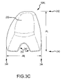
- FIGS. 20A and 20B are, respectively, exterior and interior perspective views of the resulting tibia jig model 746 after having “saw cut and drill hole data” 44 integrated into the jig model 746 to become an integrated or complete jig model 748 generally corresponding to the “integrated jig data” 48 discussed with respect to [block 150 ] of FIG. 1E .
- the integrated jig model 748 may include a jig body 850 , a medial tibia plateau covering projection 852 , a lateral tibia plateau covering projection 854 , a lower portion 856 extending form the body 850 , posterior drill holes 32 P, anterior drill holes 32 A, a saw slot 30 and an upper flat portion 857 for receiving thereon patient, surgery and physician data.
- the projections 852 , 854 extend over their respective medial and lateral tibia plateau portions.
- the projections 852 , 854 , 856 , 857 extend integrally from the jig body 850 .
- the angular difference w j may indicate whether portions of the contour line segment in the irregular region 2402 C are too eccentric for use in constructing the 3D models 40 .
- the angular difference w j may be compared to a predetermined angular criterion w c . If the angular criterion w c is set to 5 degrees, the angular differences between adjacent tangent lines associated with j ⁇ 6, j ⁇ 5, j ⁇ 4, j ⁇ 3, j ⁇ 2 and j ⁇ 1 are within the predetermined angular criterion w c .
- points A, A′ and A′′ are in close proximity to each other due to the close proximity of their respective contour line segments.
- the close proximity of the respective contour lines is a result of the rise or fall distances d AA′ and d A′A′′ being small at points A, A′ and A′′, as the contour lines m th , m th+1 and m th+2 at all points A, A′, A′′, B, B′, B′′, C, C′ and C′′ are evenly spaced medially-laterally due to having equal slice thicknesses D T .
- the contour lines 3707 - 3710 in the region 3714 converge such that there is little, if any, amount of rise or fall distance between adjacent contour lines.
- the contour lines 3707 - 3710 in the region 3716 converge such that there is little, if any, amount of rise or fall distance between adjacent contour lines.
- such contour lines 3707 - 3710 in the regions 3714 and 3716 would likely meet the first angular criterion ⁇ c .
- the separation distance d may be either uniform along the contour line 4300 , or may be non-uniform.
- areas of bone irregularities may have points that are closer together than areas where no irregularities are present.
- the points shown along the example contour line 4300 may have a separation distance d of approximately 2 mm. In other embodiments, distance d may be in the range of approximately 0.8 mm to approximately 5 mm.
- FIGS. 46A-B show similar analyses of the regular regions 4302 A and 4302 C (from FIG. 43 ).
- points i+1, i+2, i+3, . . . , i+n and j+1, j+2, j+3, . . . , j+n along the contour line 4300 may be identified for regions 4302 A and 4302 C and then tangent lines (labeled as t j+1 , t j+2 , t j+3 , etc. and t i+1 , t i+2 , t i+3 , etc.) may be constructed per block 2506 .
- Per block 2508 comparing the angular differences w between these tangent lines using the formulas
- These mating surfaces 40 - 5204 - 1 , 40 - 5204 - 2 , 40 - 5204 - 3 may have respective sub region bone mating surfaces 40 - 5204 - 1 A, 40 - 5204 - 2 A, 40 - 5204 - 3 A, with the areas of the mating surfaces 40 - 5204 - 1 , 40 - 5204 - 2 , 40 - 5204 - 3 outside the respective sub region bone mating surfaces 40 - 5204 - 1 A, 40 - 5204 - 2 A, 40 - 5204 - 3 A being the result of the overestimation process so as to not contact the corresponding bone surfaces when the respective sub region bone mating surfaces 40 - 5204 - 1 A, 40 - 5204 - 2 A, 40 - 5204 - 3 A matingly receive and contact their respective corresponding bone surfaces.
Abstract
Description
wherein P(i,j) represents a matrix of vertices with nrows=(k1+1) and ncols=(k2+1), W(ij) represents a matrix of vertex weights of one per vertex point, bi(s) represents a row-direction basis or blending of polynomial functions of degree M1, bj(t) represents a column-direction basis or blending polynomial functions of degree M2, s represents a parameter array of row-direction knots, and t represents a parameter array of column-direction knots.
evaluated over the unit square,
where is a Bernstein polynomial and
is the binomial coefficient. See Grune et al, On Numerical Algorithm and Interactive Visualization for Optimal Control Problems, Journal of Computation and Visualization in Science, Vol. 1, No. 4, July 1999, which is hereby incorporated by reference in its entirety into this Detailed Description.
wherein P(i,j) represents a matrix of vertices with nrows=(k1+1) and ncols=(k2+1), W(i,j) represents a matrix of vertex weights of one per vertex point, bi(s) represents a row-direction basis or blending of polynomial functions of degree M1, bj(t) represents a column-direction basis or blending polynomial functions of degree M2, s represents a parameter array of row-direction knots, and t represents a parameter array of column-direction knots.
evaluated over the unit square, where
is a Bernstein polynomial and
is the binomial coefficient. See Grune et al, On Numerical Algorithm and Interactive Visualization for Optimal Control Problems, Journal of Computation and Visualization in Science, Vol. 1, No. 4, July 1999, which is hereby incorporated by reference in its entirety into this Detailed Description.
In some embodiments, the operations of
between subsequent points tj and tj+1. Other embodiments include analysis between non-subsequent points (e.g., tj+2 and tj+4).
shows that they are within the angular criterion wc, which in this example is 5 degrees. Thus, the points shown in
Ideally if there were no surface variation between points A and A′, then the length of line segment AA′ would be equal to the slice thickness DT and the angular deviation θAA′ between the corresponding coordinate points A and A′ of contour lines mth and mth+1 would be zero.
Similarly, the angular differences φA′-A″ of normal vectors NVA′ and NVA″ associated with respective corresponding coordinate points A′ and A″ of respective contour lines mth+1 and mth+2 may be determined with the following formula:
Similarly, the angular differences φB′-B″ of normal vectors NVB′ and NVB″ associated with respective corresponding coordinate points B′ and B″ of respective contour lines mth+1 and mth+2 may be determined with the following formula:
Similarly, the angular differences φC′-C″ of normal vectors NVC′ and NVC″ associated with respective corresponding coordinate points C′ and C″ of respective contour lines mth+1 and mth+2 may be determined with the following formula:
In some embodiments, the operations of
shows that they wj, wi are within the angular criterion wc, which in this example is 5 degrees. Thus, the points of the
Claims (41)
Priority Applications (42)
| Application Number | Priority Date | Filing Date | Title |
|---|---|---|---|
| US12/505,056 US8777875B2 (en) | 2008-07-23 | 2009-07-17 | System and method for manufacturing arthroplasty jigs having improved mating accuracy |
| CN200980136943.4A CN102164564B (en) | 2008-07-23 | 2009-07-20 | System and method for manufacturing arthroplasty jigs having improved mating accuracy |
| PCT/US2009/051109 WO2010011590A1 (en) | 2008-07-23 | 2009-07-20 | System and method for manufacturing arthroplasty jigs having improved mating accuracy |
| AU2009274214A AU2009274214B2 (en) | 2008-07-23 | 2009-07-20 | System and method for manufacturing arthroplasty jigs having improved mating accuracy |
| EP09800841.0A EP2339991B1 (en) | 2008-07-23 | 2009-07-20 | Method for manufacturing arthroplasty jigs having improved mating accuracy |
| CA2730947A CA2730947C (en) | 2008-07-23 | 2009-07-20 | System and method for manufacturing arthroplasty jigs having improved mating accuracy |
| TW098124837A TW201004599A (en) | 2008-07-23 | 2009-07-23 | System and method for manufacturing arthroplasty jigs having improved mating accuracy |
| US12/563,809 US8545509B2 (en) | 2007-12-18 | 2009-09-21 | Arthroplasty system and related methods |
| EP09823986.6A EP2365782B1 (en) | 2008-10-03 | 2009-09-30 | Arthroplasty methods |
| PCT/US2009/058946 WO2010051122A1 (en) | 2008-10-03 | 2009-09-30 | Arthroplasty system and related methods |
| US12/760,388 US8737700B2 (en) | 2007-12-18 | 2010-04-14 | Preoperatively planning an arthroplasty procedure and generating a corresponding patient specific arthroplasty resection guide |
| US13/086,275 US8617171B2 (en) | 2007-12-18 | 2011-04-13 | Preoperatively planning an arthroplasty procedure and generating a corresponding patient specific arthroplasty resection guide |
| US13/731,850 US8961527B2 (en) | 2008-07-23 | 2012-12-31 | System and method for manufacturing arthroplasty jigs having improved mating accuracy |
| US14/011,998 US9649170B2 (en) | 2007-12-18 | 2013-08-28 | Arthroplasty system and related methods |
| US14/084,255 US9782226B2 (en) | 2007-12-18 | 2013-11-19 | Preoperatively planning an arthroplasty procedure and generating a corresponding patient specific arthroplasty resection guide |
| US14/476,500 US9451970B2 (en) | 2008-07-23 | 2014-09-03 | Arthroplasty jigs with mating accuracy |
| US15/134,290 US10456204B2 (en) | 2007-12-18 | 2016-04-20 | Preoperatively planning an arthroplasty procedure and generating a corresponding patient specific arthroplasty resection guide |
| US15/134,269 US10470823B2 (en) | 2007-12-18 | 2016-04-20 | Preoperatively planning an arthroplasty procedure and generating a corresponding patient specific arthroplasty resection guide |
| US15/134,248 US10449001B2 (en) | 2007-12-18 | 2016-04-20 | Preoperatively planning an arthroplasty procedure and generating a corresponding patient specific arthroplasty resection guide |
| US15/134,224 US10456203B2 (en) | 2007-12-18 | 2016-04-20 | Preoperatively planning an arthroplasty procedure and generating a corresponding patient specific arthroplasty resection guide |
| US15/167,710 US10182870B2 (en) | 2007-12-18 | 2016-05-27 | Preoperatively planning an arthroplasty procedure and generating a corresponding patient specific arthroplasty resection guide |
| US15/167,614 US9549782B2 (en) | 2007-12-18 | 2016-05-27 | Preoperatively planning an arthroplasty procedure and generating a corresponding patient specific arthroplasty resection guide |
| US15/168,405 US9782227B2 (en) | 2007-12-18 | 2016-05-31 | Preoperatively planning an arthroplasty procedure and generating a corresponding patient specific arthroplasty resection guide |
| US15/168,359 US9814533B2 (en) | 2007-12-18 | 2016-05-31 | Preoperatively planning an arthroplasty procedure and generating a corresponding patient specific arthroplasty resection guide |
| US15/242,312 US9636120B2 (en) | 2008-07-23 | 2016-08-19 | Arthroplasty jigs with mating accuracy |
| US15/469,171 US9839485B2 (en) | 2008-07-23 | 2017-03-24 | Arthroplasty jigs with mating accuracy |
| US15/468,867 US20170209219A1 (en) | 2008-07-23 | 2017-03-24 | Knee arthroplasty procedures |
| US15/483,560 US10194989B2 (en) | 2007-12-18 | 2017-04-10 | Arthroplasty system and related methods |
| US15/802,137 US10034714B2 (en) | 2008-07-23 | 2017-11-02 | Arthroplasty jigs with mating accuracy |
| US16/017,320 US10617475B2 (en) | 2008-07-23 | 2018-06-25 | Arthroplasty jigs with mating accuracy |
| US16/211,735 US11033334B2 (en) | 2007-12-18 | 2018-12-06 | Methods of preoperatively planning and performing an arthroplasty procedure |
| US16/256,761 US11344370B2 (en) | 2007-12-18 | 2019-01-24 | Arthroplasty system and related methods |
| US16/376,362 US10687856B2 (en) | 2007-12-18 | 2019-04-05 | System and method for image segmentation, bone model generation and modification, and surgical planning |
| US16/431,394 US11129678B2 (en) | 2008-07-23 | 2019-06-04 | Arthroplasty jigs with mating accuracy |
| US16/522,281 US10575875B2 (en) | 2007-12-18 | 2019-07-25 | Systems and methods for surgical planning of arthroplasty procedures |
| US16/803,664 US11033300B2 (en) | 2007-12-18 | 2020-02-27 | Systems and methods for surgical planning of arthroplasty procedures |
| US16/865,998 US11045227B2 (en) | 2007-12-18 | 2020-05-04 | System and method for image segmentation, bone model generation and modification, and surgical planning |
| US16/923,548 US11045228B2 (en) | 2007-12-18 | 2020-07-08 | Preoperatively planning an arthroplasty procedure and generating a corresponding patient specific arthroplasty resection guide |
| US17/018,777 US10993744B2 (en) | 2007-12-18 | 2020-09-11 | Preoperatively planning an arthroplasty procedure and generating a corresponding patient specific arthroplasty resection guide |
| US17/246,604 US11819282B2 (en) | 2007-12-18 | 2021-05-01 | Systems and methods for surgical planning of arthroplasty procedures |
| US17/326,069 US11847755B2 (en) | 2007-12-18 | 2021-05-20 | System and method for image segmentation, bone model generation and modification, and surgical planning |
| US18/379,806 US20240050155A1 (en) | 2007-12-18 | 2023-10-13 | Systems and methods for surgical planning of arthroplasty procedures |
Applications Claiming Priority (2)
| Application Number | Priority Date | Filing Date | Title |
|---|---|---|---|
| US8305308P | 2008-07-23 | 2008-07-23 | |
| US12/505,056 US8777875B2 (en) | 2008-07-23 | 2009-07-17 | System and method for manufacturing arthroplasty jigs having improved mating accuracy |
Related Parent Applications (10)
| Application Number | Title | Priority Date | Filing Date |
|---|---|---|---|
| US11/959,344 Continuation-In-Part US8221430B2 (en) | 2007-12-18 | 2007-12-18 | System and method for manufacturing arthroplasty jigs |
| US12/111,924 Continuation-In-Part US8480679B2 (en) | 2007-12-18 | 2008-04-29 | Generation of a computerized bone model representative of a pre-degenerated state and useable in the design and manufacture of arthroplasty devices |
| US12/386,105 Continuation-In-Part US8311306B2 (en) | 2007-12-18 | 2009-04-14 | System and method for image segmentation in generating computer models of a joint to undergo arthroplasty |
| US12/505,056 Continuation-In-Part US8777875B2 (en) | 2007-12-18 | 2009-07-17 | System and method for manufacturing arthroplasty jigs having improved mating accuracy |
| US12/505,056 Continuation US8777875B2 (en) | 2007-12-18 | 2009-07-17 | System and method for manufacturing arthroplasty jigs having improved mating accuracy |
| US12/546,545 Continuation-In-Part US8715291B2 (en) | 2007-12-18 | 2009-08-24 | Arthroplasty system and related methods |
| US12/760,388 Continuation-In-Part US8737700B2 (en) | 2007-12-18 | 2010-04-14 | Preoperatively planning an arthroplasty procedure and generating a corresponding patient specific arthroplasty resection guide |
| PCT/US2014/030496 Continuation-In-Part WO2014145691A1 (en) | 2007-12-18 | 2014-03-17 | Generation of a mating surface model for patient specific cutting guide based on anatomical model segmentation |
| US14/776,660 Continuation-In-Part US10912571B2 (en) | 2013-03-15 | 2014-03-17 | Generation of a mating surface model for patient specific cutting guide based on anatomical model segmentation |
| US16/211,735 Continuation-In-Part US11033334B2 (en) | 2007-12-18 | 2018-12-06 | Methods of preoperatively planning and performing an arthroplasty procedure |
Related Child Applications (9)
| Application Number | Title | Priority Date | Filing Date |
|---|---|---|---|
| US11/959,344 Continuation-In-Part US8221430B2 (en) | 2007-12-18 | 2007-12-18 | System and method for manufacturing arthroplasty jigs |
| US12/111,924 Continuation-In-Part US8480679B2 (en) | 2007-12-18 | 2008-04-29 | Generation of a computerized bone model representative of a pre-degenerated state and useable in the design and manufacture of arthroplasty devices |
| US12/505,056 Continuation-In-Part US8777875B2 (en) | 2007-12-18 | 2009-07-17 | System and method for manufacturing arthroplasty jigs having improved mating accuracy |
| US12/505,056 Continuation US8777875B2 (en) | 2007-12-18 | 2009-07-17 | System and method for manufacturing arthroplasty jigs having improved mating accuracy |
| US12/546,545 Continuation-In-Part US8715291B2 (en) | 2007-12-18 | 2009-08-24 | Arthroplasty system and related methods |
| US12/563,809 Continuation-In-Part US8545509B2 (en) | 2007-12-18 | 2009-09-21 | Arthroplasty system and related methods |
| US13/731,850 Division US8961527B2 (en) | 2007-12-18 | 2012-12-31 | System and method for manufacturing arthroplasty jigs having improved mating accuracy |
| US13/731,850 Continuation US8961527B2 (en) | 2007-12-18 | 2012-12-31 | System and method for manufacturing arthroplasty jigs having improved mating accuracy |
| PCT/US2014/030496 Continuation-In-Part WO2014145691A1 (en) | 2007-12-18 | 2014-03-17 | Generation of a mating surface model for patient specific cutting guide based on anatomical model segmentation |
Publications (2)
| Publication Number | Publication Date |
|---|---|
| US20100023015A1 US20100023015A1 (en) | 2010-01-28 |
| US8777875B2 true US8777875B2 (en) | 2014-07-15 |
Family
ID=41569317
Family Applications (8)
| Application Number | Title | Priority Date | Filing Date |
|---|---|---|---|
| US12/505,056 Active 2032-03-04 US8777875B2 (en) | 2007-12-18 | 2009-07-17 | System and method for manufacturing arthroplasty jigs having improved mating accuracy |
| US13/731,850 Active 2029-12-14 US8961527B2 (en) | 2007-12-18 | 2012-12-31 | System and method for manufacturing arthroplasty jigs having improved mating accuracy |
| US14/476,500 Active US9451970B2 (en) | 2007-12-18 | 2014-09-03 | Arthroplasty jigs with mating accuracy |
| US15/242,312 Active US9636120B2 (en) | 2007-12-18 | 2016-08-19 | Arthroplasty jigs with mating accuracy |
| US15/469,171 Active US9839485B2 (en) | 2007-12-18 | 2017-03-24 | Arthroplasty jigs with mating accuracy |
| US15/802,137 Active US10034714B2 (en) | 2007-12-18 | 2017-11-02 | Arthroplasty jigs with mating accuracy |
| US16/017,320 Active 2029-11-07 US10617475B2 (en) | 2007-12-18 | 2018-06-25 | Arthroplasty jigs with mating accuracy |
| US16/431,394 Active 2030-07-02 US11129678B2 (en) | 2008-07-23 | 2019-06-04 | Arthroplasty jigs with mating accuracy |
Family Applications After (7)
| Application Number | Title | Priority Date | Filing Date |
|---|---|---|---|
| US13/731,850 Active 2029-12-14 US8961527B2 (en) | 2007-12-18 | 2012-12-31 | System and method for manufacturing arthroplasty jigs having improved mating accuracy |
| US14/476,500 Active US9451970B2 (en) | 2007-12-18 | 2014-09-03 | Arthroplasty jigs with mating accuracy |
| US15/242,312 Active US9636120B2 (en) | 2007-12-18 | 2016-08-19 | Arthroplasty jigs with mating accuracy |
| US15/469,171 Active US9839485B2 (en) | 2007-12-18 | 2017-03-24 | Arthroplasty jigs with mating accuracy |
| US15/802,137 Active US10034714B2 (en) | 2007-12-18 | 2017-11-02 | Arthroplasty jigs with mating accuracy |
| US16/017,320 Active 2029-11-07 US10617475B2 (en) | 2007-12-18 | 2018-06-25 | Arthroplasty jigs with mating accuracy |
| US16/431,394 Active 2030-07-02 US11129678B2 (en) | 2008-07-23 | 2019-06-04 | Arthroplasty jigs with mating accuracy |
Country Status (7)
| Country | Link |
|---|---|
| US (8) | US8777875B2 (en) |
| EP (1) | EP2339991B1 (en) |
| CN (1) | CN102164564B (en) |
| AU (1) | AU2009274214B2 (en) |
| CA (1) | CA2730947C (en) |
| TW (1) | TW201004599A (en) |
| WO (1) | WO2010011590A1 (en) |
Cited By (90)
| Publication number | Priority date | Publication date | Assignee | Title |
|---|---|---|---|---|
| US20130066319A1 (en) * | 2010-02-25 | 2013-03-14 | Luke J. Aram | Method of fabricating customized patient-specific bone cutting blocks |
| US20140066938A1 (en) * | 2011-06-13 | 2014-03-06 | Materialise Nv | Patient-specific partial knee guides and other instruments |
| US20140135775A1 (en) * | 2010-02-26 | 2014-05-15 | Biomet Sports Medicine, Llc | Patient-Specific Osteotomy Devices And Methods |
| US8979936B2 (en) | 2006-06-09 | 2015-03-17 | Biomet Manufacturing, Llc | Patient-modified implant |
| US8998909B2 (en) | 2012-12-20 | 2015-04-07 | Bullseye Hip Replacement, Llc | Devices and methods for hip replacement |
| US9005297B2 (en) | 2006-02-27 | 2015-04-14 | Biomet Manufacturing, Llc | Patient-specific elbow guides and associated methods |
| US9060788B2 (en) | 2012-12-11 | 2015-06-23 | Biomet Manufacturing, Llc | Patient-specific acetabular guide for anterior approach |
| US9066734B2 (en) | 2011-08-31 | 2015-06-30 | Biomet Manufacturing, Llc | Patient-specific sacroiliac guides and associated methods |
| US9084618B2 (en) | 2011-06-13 | 2015-07-21 | Biomet Manufacturing, Llc | Drill guides for confirming alignment of patient-specific alignment guides |
| US9113971B2 (en) | 2006-02-27 | 2015-08-25 | Biomet Manufacturing, Llc | Femoral acetabular impingement guide |
| US9173666B2 (en) | 2011-07-01 | 2015-11-03 | Biomet Manufacturing, Llc | Patient-specific-bone-cutting guidance instruments and methods |
| US9173661B2 (en) | 2006-02-27 | 2015-11-03 | Biomet Manufacturing, Llc | Patient specific alignment guide with cutting surface and laser indicator |
| US9208263B2 (en) | 2008-04-30 | 2015-12-08 | Howmedica Osteonics Corporation | System and method for image segmentation in generating computer models of a joint to undergo arthroplasty |
| US9204977B2 (en) | 2012-12-11 | 2015-12-08 | Biomet Manufacturing, Llc | Patient-specific acetabular guide for anterior approach |
| US9211128B2 (en) | 2014-04-17 | 2015-12-15 | Bullseye Hip Replacement, Llc | Devices and methods for hip replacement |
| US9237950B2 (en) | 2012-02-02 | 2016-01-19 | Biomet Manufacturing, Llc | Implant with patient-specific porous structure |
| US9241745B2 (en) | 2011-03-07 | 2016-01-26 | Biomet Manufacturing, Llc | Patient-specific femoral version guide |
| US20160022370A1 (en) * | 2013-03-15 | 2016-01-28 | Otismed Corporation | Generation of a Mating Surface Model for Patient Specific Cutting Guide Based on Anatomical Model Segmentation |
| US9271744B2 (en) | 2010-09-29 | 2016-03-01 | Biomet Manufacturing, Llc | Patient-specific guide for partial acetabular socket replacement |
| US9289253B2 (en) | 2006-02-27 | 2016-03-22 | Biomet Manufacturing, Llc | Patient-specific shoulder guide |
| US9295497B2 (en) | 2011-08-31 | 2016-03-29 | Biomet Manufacturing, Llc | Patient-specific sacroiliac and pedicle guides |
| US9301812B2 (en) | 2011-10-27 | 2016-04-05 | Biomet Manufacturing, Llc | Methods for patient-specific shoulder arthroplasty |
| US9339278B2 (en) | 2006-02-27 | 2016-05-17 | Biomet Manufacturing, Llc | Patient-specific acetabular guides and associated instruments |
| US9345548B2 (en) | 2006-02-27 | 2016-05-24 | Biomet Manufacturing, Llc | Patient-specific pre-operative planning |
| US9351743B2 (en) | 2011-10-27 | 2016-05-31 | Biomet Manufacturing, Llc | Patient-specific glenoid guides |
| US9386993B2 (en) | 2011-09-29 | 2016-07-12 | Biomet Manufacturing, Llc | Patient-specific femoroacetabular impingement instruments and methods |
| US9393028B2 (en) | 2009-08-13 | 2016-07-19 | Biomet Manufacturing, Llc | Device for the resection of bones, method for producing such a device, endoprosthesis suited for this purpose and method for producing such an endoprosthesis |
| US9402637B2 (en) | 2012-10-11 | 2016-08-02 | Howmedica Osteonics Corporation | Customized arthroplasty cutting guides and surgical methods using the same |
| US9408618B2 (en) | 2008-02-29 | 2016-08-09 | Howmedica Osteonics Corporation | Total hip replacement surgical guide tool |
| US9408616B2 (en) | 2014-05-12 | 2016-08-09 | Biomet Manufacturing, Llc | Humeral cut guide |
| US20160231732A1 (en) * | 2015-02-10 | 2016-08-11 | Siemens Aktiengesellschaft | Method for generating a manufacturing model for a medical implant |
| US9414938B2 (en) | 2014-09-12 | 2016-08-16 | Bullseye Hip Replacement, Llc | Devices and methods for hip replacement |
| US9414846B2 (en) | 2014-10-22 | 2016-08-16 | Bullseye Hip Replacement, Llc | Devices and methods for knee replacement |
| US9427320B2 (en) | 2011-08-04 | 2016-08-30 | Biomet Manufacturing, Llc | Patient-specific pelvic implants for acetabular reconstruction |
| US9445907B2 (en) | 2011-03-07 | 2016-09-20 | Biomet Manufacturing, Llc | Patient-specific tools and implants |
| US9451973B2 (en) | 2011-10-27 | 2016-09-27 | Biomet Manufacturing, Llc | Patient specific glenoid guide |
| US9451970B2 (en) | 2008-07-23 | 2016-09-27 | Howmedica Osteonics Corporation | Arthroplasty jigs with mating accuracy |
| US9474539B2 (en) | 2011-04-29 | 2016-10-25 | Biomet Manufacturing, Llc | Patient-specific convertible guides |
| US9480580B2 (en) | 2006-02-27 | 2016-11-01 | Biomet Manufacturing, Llc | Patient-specific acetabular alignment guides |
| US9480490B2 (en) | 2006-02-27 | 2016-11-01 | Biomet Manufacturing, Llc | Patient-specific guides |
| US9498233B2 (en) | 2013-03-13 | 2016-11-22 | Biomet Manufacturing, Llc. | Universal acetabular guide and associated hardware |
| US9517145B2 (en) | 2013-03-15 | 2016-12-13 | Biomet Manufacturing, Llc | Guide alignment system and method |
| US9522010B2 (en) | 2006-02-27 | 2016-12-20 | Biomet Manufacturing, Llc | Patient-specific orthopedic instruments |
| US9554910B2 (en) | 2011-10-27 | 2017-01-31 | Biomet Manufacturing, Llc | Patient-specific glenoid guide and implants |
| US9561040B2 (en) | 2014-06-03 | 2017-02-07 | Biomet Manufacturing, Llc | Patient-specific glenoid depth control |
| US9572590B2 (en) | 2006-10-03 | 2017-02-21 | Biomet Uk Limited | Surgical instrument |
| US9572682B2 (en) | 2011-09-29 | 2017-02-21 | Arthromeda, Inc. | System and method for precise prosthesis positioning in hip arthroplasty |
| US9579107B2 (en) | 2013-03-12 | 2017-02-28 | Biomet Manufacturing, Llc | Multi-point fit for patient specific guide |
| US9585725B2 (en) | 2002-03-20 | 2017-03-07 | P Tech, Llc | Robotic arthroplasty system |
| US9597096B2 (en) | 2013-03-15 | 2017-03-21 | Arthromeda, Inc. | Systems and methods for providing alignment in total knee arthroplasty |
| US9646113B2 (en) | 2008-04-29 | 2017-05-09 | Howmedica Osteonics Corporation | Generation of a computerized bone model representative of a pre-degenerated state and useable in the design and manufacture of arthroplasty devices |
| US9662127B2 (en) | 2006-02-27 | 2017-05-30 | Biomet Manufacturing, Llc | Patient-specific acetabular guides and associated instruments |
| US9662216B2 (en) | 2006-02-27 | 2017-05-30 | Biomet Manufacturing, Llc | Patient-specific hip joint devices |
| US9675400B2 (en) | 2011-04-19 | 2017-06-13 | Biomet Manufacturing, Llc | Patient-specific fracture fixation instrumentation and method |
| US9717510B2 (en) | 2011-04-15 | 2017-08-01 | Biomet Manufacturing, Llc | Patient-specific numerically controlled instrument |
| US9730713B2 (en) | 2002-05-15 | 2017-08-15 | Howmedica Osteonics Corporation | Arthroplasty jig |
| US9743940B2 (en) | 2011-04-29 | 2017-08-29 | Biomet Manufacturing, Llc | Patient-specific partial knee guides and other instruments |
| US9757238B2 (en) | 2011-06-06 | 2017-09-12 | Biomet Manufacturing, Llc | Pre-operative planning and manufacturing method for orthopedic procedure |
| US9763683B2 (en) | 2001-08-28 | 2017-09-19 | Bonutti Skeletal Innovations Llc | Method for performing surgical procedures using optical cutting guides |
| US9782226B2 (en) | 2007-12-18 | 2017-10-10 | Howmedica Osteonics Corporation | Preoperatively planning an arthroplasty procedure and generating a corresponding patient specific arthroplasty resection guide |
| US9788846B2 (en) | 2008-12-16 | 2017-10-17 | Howmedica Osteonics Corporation | Unicompartmental customized arthroplasty cutting jigs |
| US9795394B2 (en) | 2000-01-14 | 2017-10-24 | Bonutti Skeletal Innovations Llc | Method for placing implant using robotic system |
| US9795399B2 (en) | 2006-06-09 | 2017-10-24 | Biomet Manufacturing, Llc | Patient-specific knee alignment guide and associated method |
| US9820868B2 (en) | 2015-03-30 | 2017-11-21 | Biomet Manufacturing, Llc | Method and apparatus for a pin apparatus |
| US9826981B2 (en) | 2013-03-13 | 2017-11-28 | Biomet Manufacturing, Llc | Tangential fit of patient-specific guides |
| US9826994B2 (en) | 2014-09-29 | 2017-11-28 | Biomet Manufacturing, Llc | Adjustable glenoid pin insertion guide |
| US9833245B2 (en) | 2014-09-29 | 2017-12-05 | Biomet Sports Medicine, Llc | Tibial tubercule osteotomy |
| US9839438B2 (en) | 2013-03-11 | 2017-12-12 | Biomet Manufacturing, Llc | Patient-specific glenoid guide with a reusable guide holder |
| US9839436B2 (en) | 2014-06-03 | 2017-12-12 | Biomet Manufacturing, Llc | Patient-specific glenoid depth control |
| US9907659B2 (en) | 2007-04-17 | 2018-03-06 | Biomet Manufacturing, Llc | Method and apparatus for manufacturing an implant |
| US9918740B2 (en) | 2006-02-27 | 2018-03-20 | Biomet Manufacturing, Llc | Backup surgical instrument system and method |
| US9968376B2 (en) | 2010-11-29 | 2018-05-15 | Biomet Manufacturing, Llc | Patient-specific orthopedic instruments |
| US10058393B2 (en) | 2015-10-21 | 2018-08-28 | P Tech, Llc | Systems and methods for navigation and visualization |
| US10159498B2 (en) | 2008-04-16 | 2018-12-25 | Biomet Manufacturing, Llc | Method and apparatus for manufacturing an implant |
| US10226262B2 (en) | 2015-06-25 | 2019-03-12 | Biomet Manufacturing, Llc | Patient-specific humeral guide designs |
| US10278711B2 (en) | 2006-02-27 | 2019-05-07 | Biomet Manufacturing, Llc | Patient-specific femoral guide |
| US10282488B2 (en) | 2014-04-25 | 2019-05-07 | Biomet Manufacturing, Llc | HTO guide with optional guided ACL/PCL tunnels |
| US10492798B2 (en) | 2011-07-01 | 2019-12-03 | Biomet Manufacturing, Llc | Backup kit for a patient-specific arthroplasty kit assembly |
| US10568647B2 (en) | 2015-06-25 | 2020-02-25 | Biomet Manufacturing, Llc | Patient-specific humeral guide designs |
| US10603179B2 (en) | 2006-02-27 | 2020-03-31 | Biomet Manufacturing, Llc | Patient-specific augments |
| US10722310B2 (en) | 2017-03-13 | 2020-07-28 | Zimmer Biomet CMF and Thoracic, LLC | Virtual surgery planning system and method |
| US10828046B2 (en) | 2007-09-30 | 2020-11-10 | DePuy Synthes Products, Inc. | Apparatus and method for fabricating a customized patient-specific orthopaedic instrument |
| US10940666B2 (en) | 2017-05-26 | 2021-03-09 | Howmedica Osteonics Corp. | Packaging structures and additive manufacturing thereof |
| US10987176B2 (en) | 2018-06-19 | 2021-04-27 | Tornier, Inc. | Virtual guidance for orthopedic surgical procedures |
| US11051829B2 (en) | 2018-06-26 | 2021-07-06 | DePuy Synthes Products, Inc. | Customized patient-specific orthopaedic surgical instrument |
| US11160568B1 (en) | 2019-09-10 | 2021-11-02 | Lento Medical, Inc | Optimal selection of contact curves |
| US11179165B2 (en) | 2013-10-21 | 2021-11-23 | Biomet Manufacturing, Llc | Ligament guide registration |
| US11406503B2 (en) * | 2010-09-01 | 2022-08-09 | Mayo Foundation For Medical Education And Research | Method for optimization of joint arthroplasty component design |
| US11419618B2 (en) | 2011-10-27 | 2022-08-23 | Biomet Manufacturing, Llc | Patient-specific glenoid guides |
| US11813167B2 (en) | 2017-05-15 | 2023-11-14 | Howmedica Osteonics Corp. | Patellofemoral implant |
Families Citing this family (151)
| Publication number | Priority date | Publication date | Assignee | Title |
|---|---|---|---|---|
| US8234097B2 (en) * | 2001-05-25 | 2012-07-31 | Conformis, Inc. | Automated systems for manufacturing patient-specific orthopedic implants and instrumentation |
| US9017336B2 (en) * | 2006-02-15 | 2015-04-28 | Otismed Corporation | Arthroplasty devices and related methods |
| US9808262B2 (en) | 2006-02-15 | 2017-11-07 | Howmedica Osteonics Corporation | Arthroplasty devices and related methods |
| US8133234B2 (en) * | 2006-02-27 | 2012-03-13 | Biomet Manufacturing Corp. | Patient specific acetabular guide and method |
| US8070752B2 (en) * | 2006-02-27 | 2011-12-06 | Biomet Manufacturing Corp. | Patient specific alignment guide and inter-operative adjustment |
| US20110190899A1 (en) * | 2006-02-27 | 2011-08-04 | Biomet Manufacturing Corp. | Patient-specific augments |
| US8298237B2 (en) * | 2006-06-09 | 2012-10-30 | Biomet Manufacturing Corp. | Patient-specific alignment guide for multiple incisions |
| US20110172672A1 (en) * | 2006-02-27 | 2011-07-14 | Biomet Manufacturing Corp. | Instrument with transparent portion for use with patient-specific alignment guide |
| US8473305B2 (en) | 2007-04-17 | 2013-06-25 | Biomet Manufacturing Corp. | Method and apparatus for manufacturing an implant |
| US8241293B2 (en) * | 2006-02-27 | 2012-08-14 | Biomet Manufacturing Corp. | Patient specific high tibia osteotomy |
| US8864769B2 (en) * | 2006-02-27 | 2014-10-21 | Biomet Manufacturing, Llc | Alignment guides with patient-specific anchoring elements |
| US8858561B2 (en) * | 2006-06-09 | 2014-10-14 | Blomet Manufacturing, LLC | Patient-specific alignment guide |
| US8092465B2 (en) | 2006-06-09 | 2012-01-10 | Biomet Manufacturing Corp. | Patient specific knee alignment guide and associated method |
| US8282646B2 (en) | 2006-02-27 | 2012-10-09 | Biomet Manufacturing Corp. | Patient specific knee alignment guide and associated method |
| US8460302B2 (en) * | 2006-12-18 | 2013-06-11 | Otismed Corporation | Arthroplasty devices and related methods |
| CA2882265C (en) | 2007-08-17 | 2017-01-03 | Zimmer, Inc. | Implant design analysis suite |
| US8265949B2 (en) | 2007-09-27 | 2012-09-11 | Depuy Products, Inc. | Customized patient surgical plan |
| US9173662B2 (en) | 2007-09-30 | 2015-11-03 | DePuy Synthes Products, Inc. | Customized patient-specific tibial cutting blocks |
| WO2011106400A1 (en) * | 2010-02-25 | 2011-09-01 | Depuy Products, Inc. | Customized patient-specific tibial cutting blocks |
| US9786022B2 (en) | 2007-09-30 | 2017-10-10 | DePuy Synthes Products, Inc. | Customized patient-specific bone cutting blocks |
| US8357111B2 (en) | 2007-09-30 | 2013-01-22 | Depuy Products, Inc. | Method and system for designing patient-specific orthopaedic surgical instruments |
| USD642263S1 (en) | 2007-10-25 | 2011-07-26 | Otismed Corporation | Arthroplasty jig blank |
| US8460303B2 (en) | 2007-10-25 | 2013-06-11 | Otismed Corporation | Arthroplasty systems and devices, and related methods |
| US10582934B2 (en) * | 2007-11-27 | 2020-03-10 | Howmedica Osteonics Corporation | Generating MRI images usable for the creation of 3D bone models employed to make customized arthroplasty jigs |
| CA2732274C (en) | 2007-12-06 | 2017-03-28 | Smith & Nephew, Inc. | Systems and methods for determining the mechanical axis of a femur |
| US8545509B2 (en) | 2007-12-18 | 2013-10-01 | Otismed Corporation | Arthroplasty system and related methods |
| US8715291B2 (en) * | 2007-12-18 | 2014-05-06 | Otismed Corporation | Arthroplasty system and related methods |
| US8311306B2 (en) * | 2008-04-30 | 2012-11-13 | Otismed Corporation | System and method for image segmentation in generating computer models of a joint to undergo arthroplasty |
| US8737700B2 (en) * | 2007-12-18 | 2014-05-27 | Otismed Corporation | Preoperatively planning an arthroplasty procedure and generating a corresponding patient specific arthroplasty resection guide |
| US8221430B2 (en) | 2007-12-18 | 2012-07-17 | Otismed Corporation | System and method for manufacturing arthroplasty jigs |
| US8152846B2 (en) * | 2008-03-06 | 2012-04-10 | Musculoskeletal Transplant Foundation | Instrumentation and method for repair of meniscus tissue |
| US8992538B2 (en) | 2008-09-30 | 2015-03-31 | DePuy Synthes Products, Inc. | Customized patient-specific acetabular orthopaedic surgical instrument and method of use and fabrication |
| US8170641B2 (en) | 2009-02-20 | 2012-05-01 | Biomet Manufacturing Corp. | Method of imaging an extremity of a patient |
| CN102365061B (en) * | 2009-02-25 | 2015-06-17 | 捷迈有限公司 | Customized orthopaedic implants and related methods |
| US9078755B2 (en) | 2009-02-25 | 2015-07-14 | Zimmer, Inc. | Ethnic-specific orthopaedic implants and custom cutting jigs |
| BRPI1006280A2 (en) * | 2009-04-03 | 2019-04-02 | Koninl Philips Electronics Nv | an organ segmentation method, an organ segmentation system and a computer readable storage medium |
| US8794977B2 (en) * | 2009-04-29 | 2014-08-05 | Lifemodeler, Inc. | Implant training system |
| EP2493396B1 (en) * | 2009-10-29 | 2016-11-23 | Zimmer, Inc. | Patient-specific mill guide |
| EP2538853A4 (en) | 2010-02-25 | 2016-07-27 | Depuy Products Inc | Customized patient-specific bone cutting blocks |
| US9066727B2 (en) | 2010-03-04 | 2015-06-30 | Materialise Nv | Patient-specific computed tomography guides |
| US9579106B2 (en) * | 2010-03-31 | 2017-02-28 | New York Society For The Relief Of The Ruptured And Crippled, Maintaining The Hospital For Special Surgery | Shoulder arthroplasty instrumentation |
| US8805035B2 (en) * | 2010-05-03 | 2014-08-12 | Mim Software, Inc. | Systems and methods for contouring a set of medical images |
| AU2011265254B2 (en) * | 2010-06-11 | 2016-05-19 | Smith & Nephew, Inc. | Patient-matched instruments |
| US8628580B2 (en) | 2010-07-24 | 2014-01-14 | Zimmer, Inc. | Tibial prosthesis |
| EP2595574B1 (en) | 2010-07-24 | 2017-05-03 | Zimmer, Inc. | Asymmetric tibial components for a knee prosthesis |
| US8808302B2 (en) | 2010-08-12 | 2014-08-19 | DePuy Synthes Products, LLC | Customized patient-specific acetabular orthopaedic surgical instrument and method of use and fabrication |
| ES2631181T3 (en) | 2010-09-10 | 2017-08-29 | Zimmer, Inc. | Tibia components that facilitate movement for a knee prosthesis |
| EP2632350B1 (en) | 2010-10-29 | 2021-09-22 | The Cleveland Clinic Foundation | System of preoperative planning and provision of patient-specific surgical aids |
| EP2632349B1 (en) | 2010-10-29 | 2018-03-07 | The Cleveland Clinic Foundation | System for assisting with attachment of a stock implant to a patient tissue |
| CA2815655A1 (en) | 2010-10-29 | 2012-05-03 | The Cleveland Clinic Foundation | System and method for assisting with arrangement of a stock instrument with respect to a patient tissue |
| CA2816337C (en) | 2010-10-29 | 2019-10-22 | The Cleveland Clinic Foundation | System and method for association of a guiding aid with a patient tissue |
| US8603101B2 (en) | 2010-12-17 | 2013-12-10 | Zimmer, Inc. | Provisional tibial prosthesis system |
| WO2012112701A2 (en) | 2011-02-15 | 2012-08-23 | Conformis, Inc. | Patent-adapted and improved articular implants, designs, surgical procedures and related guide tools |
| WO2012154914A1 (en) | 2011-05-11 | 2012-11-15 | The Cleveland Clinic Foundation | Generating patient specific instruments for use as surgical aids |
| AU2012255850B2 (en) | 2011-05-19 | 2016-05-19 | The Cleveland Clinic Foundation | Apparatus and method for providing a reference indication to a patient tissue |
| EP2713960B1 (en) * | 2011-06-01 | 2017-03-22 | Smith & Nephew, Inc. | Patient specific instrument |
| WO2012168322A2 (en) | 2011-06-06 | 2012-12-13 | 3Shape A/S | Dual-resolution 3d scanner |
| WO2012170376A2 (en) | 2011-06-08 | 2012-12-13 | Howmedica Osteonics Corp. | Patient-specific cutting guide for the shoulder |
| BR112013032144A2 (en) | 2011-06-16 | 2016-12-13 | Smith & Nephew Inc | surgical alignment using references |
| US8641721B2 (en) | 2011-06-30 | 2014-02-04 | DePuy Synthes Products, LLC | Customized patient-specific orthopaedic pin guides |
| US10052114B2 (en) | 2011-07-12 | 2018-08-21 | Materialise, Nv | Shoulder base plate coverage and stability |
| BE1020070A5 (en) * | 2011-07-12 | 2013-04-02 | Materialise Nv | SURGICAL INSTRUMENT FOR POSITIONING AN ALIGNMENT ELEMENT. |
| EP2561814A1 (en) * | 2011-08-25 | 2013-02-27 | Deru GmbH | Cutting guide for creating an external contour for an articulated endoprosthetic |
| EP2757978B1 (en) * | 2011-09-21 | 2016-08-17 | Materialise N.V. | Patient-specific surgical guide |
| WO2013074143A1 (en) | 2011-11-18 | 2013-05-23 | Zimmer, Inc. | Tibial bearing component for a knee prosthesis with improved articular characteristics |
| JP5824163B2 (en) | 2011-11-21 | 2015-11-25 | ジンマー,インコーポレイティド | Tibial bed plate with asymmetric mounting of fixed structure |
| US11493998B2 (en) | 2012-01-17 | 2022-11-08 | Ultrahaptics IP Two Limited | Systems and methods for machine control |
| US8638989B2 (en) | 2012-01-17 | 2014-01-28 | Leap Motion, Inc. | Systems and methods for capturing motion in three-dimensional space |
| US9501152B2 (en) | 2013-01-15 | 2016-11-22 | Leap Motion, Inc. | Free-space user interface and control using virtual constructs |
| US10691219B2 (en) | 2012-01-17 | 2020-06-23 | Ultrahaptics IP Two Limited | Systems and methods for machine control |
| US9070019B2 (en) | 2012-01-17 | 2015-06-30 | Leap Motion, Inc. | Systems and methods for capturing motion in three-dimensional space |
| US9679215B2 (en) | 2012-01-17 | 2017-06-13 | Leap Motion, Inc. | Systems and methods for machine control |
| US8693731B2 (en) | 2012-01-17 | 2014-04-08 | Leap Motion, Inc. | Enhanced contrast for object detection and characterization by optical imaging |
| US20150253428A1 (en) | 2013-03-15 | 2015-09-10 | Leap Motion, Inc. | Determining positional information for an object in space |
| WO2013112688A1 (en) | 2012-01-24 | 2013-08-01 | Zimmer, Inc. | Method and system for creating patient-specific instrumentation for chondral graft transfer |
| CN104203160B (en) | 2012-01-30 | 2016-05-11 | 捷迈有限公司 | For the asymmetric shin bone part of knee-joint prosthesis |
| US20140364857A1 (en) * | 2012-02-07 | 2014-12-11 | Conformis, Inc. | Joint Arthroplasty Devices, Systems, and Methods |
| EP3181066A3 (en) * | 2012-02-09 | 2017-09-20 | MatOrtho Limited | Tool |
| IN2014DN07700A (en) * | 2012-03-21 | 2015-05-15 | Smith & Nephew Inc | |
| CA3072716C (en) | 2012-03-28 | 2022-03-22 | Orthosoft Ulc | Glenoid implant surgery using patient specific instrumentation |
| EP3187151B1 (en) * | 2012-04-13 | 2018-12-05 | ConforMIS, Inc. | Patient adapted joint arthroplasty devices and surgical tools |
| EP2854663B1 (en) | 2012-05-24 | 2022-05-25 | Zimmer Inc. | Patient-specific instrumentation for articular joint repair |
| US20140013565A1 (en) * | 2012-07-10 | 2014-01-16 | Eileen B. MacDonald | Customized process for facilitating successful total knee arthroplasty with outcomes analysis |
| WO2014015432A1 (en) | 2012-07-23 | 2014-01-30 | Orthosoft Inc. | Patient-specific instrumentation for implant revision surgery |
| AU2013296108B2 (en) | 2012-07-24 | 2017-08-31 | Orthosoft Ulc | Patient specific instrumentation with mems in surgery |
| US20150223941A1 (en) * | 2012-08-27 | 2015-08-13 | Conformis, Inc. | Methods, Devices and Techniques for Improved Placement and Fixation of Shoulder Implant Components |
| US9285893B2 (en) | 2012-11-08 | 2016-03-15 | Leap Motion, Inc. | Object detection and tracking with variable-field illumination devices |
| US8920512B2 (en) | 2012-12-19 | 2014-12-30 | Biomet Sports Medicine, Llc | Method and apparatus for pre-forming a high tibial osteotomy |
| US10609285B2 (en) | 2013-01-07 | 2020-03-31 | Ultrahaptics IP Two Limited | Power consumption in motion-capture systems |
| US9465461B2 (en) | 2013-01-08 | 2016-10-11 | Leap Motion, Inc. | Object detection and tracking with audio and optical signals |
| US9632658B2 (en) | 2013-01-15 | 2017-04-25 | Leap Motion, Inc. | Dynamic user interactions for display control and scaling responsiveness of display objects |
| US9459697B2 (en) | 2013-01-15 | 2016-10-04 | Leap Motion, Inc. | Dynamic, free-space user interactions for machine control |
| EP2956310B1 (en) * | 2013-02-13 | 2019-09-04 | Composecure, LLC | Durable card |
| US11024080B2 (en) | 2013-03-11 | 2021-06-01 | Autodesk, Inc. | Techniques for slicing a 3D model for manufacturing |
| US10054932B2 (en) * | 2013-03-11 | 2018-08-21 | Autodesk, Inc. | Techniques for two-way slicing of a 3D model for manufacturing |
| US10620709B2 (en) | 2013-04-05 | 2020-04-14 | Ultrahaptics IP Two Limited | Customized gesture interpretation |
| US9916009B2 (en) | 2013-04-26 | 2018-03-13 | Leap Motion, Inc. | Non-tactile interface systems and methods |
| US9747696B2 (en) | 2013-05-17 | 2017-08-29 | Leap Motion, Inc. | Systems and methods for providing normalized parameters of motions of objects in three-dimensional space |
| EP3007655B1 (en) | 2013-06-11 | 2020-09-02 | Orthosoft ULC | Acetabular cup prosthesis positioning instrument |
| WO2014197989A1 (en) | 2013-06-11 | 2014-12-18 | Orthosoft Inc. | Computer assisted subchondral injection |
| US10034677B2 (en) | 2013-07-23 | 2018-07-31 | Greatbatch Ltd. | Customizable joint replacement apparatus |
| US10281987B1 (en) | 2013-08-09 | 2019-05-07 | Leap Motion, Inc. | Systems and methods of free-space gestural interaction |
| US10846942B1 (en) | 2013-08-29 | 2020-11-24 | Ultrahaptics IP Two Limited | Predictive information for free space gesture control and communication |
| US9925052B2 (en) | 2013-08-30 | 2018-03-27 | Zimmer, Inc. | Method for optimizing implant designs |
| WO2015048319A1 (en) * | 2013-09-25 | 2015-04-02 | Zimmer, Inc. | Patient specific instrumentation (psi) for orthopedic surgery and systems and methods for using x-rays to produce same |
| US9632572B2 (en) | 2013-10-03 | 2017-04-25 | Leap Motion, Inc. | Enhanced field of view to augment three-dimensional (3D) sensory space for free-space gesture interpretation |
| US9996638B1 (en) | 2013-10-31 | 2018-06-12 | Leap Motion, Inc. | Predictive information for free space gesture control and communication |
| GB201320745D0 (en) | 2013-11-25 | 2014-01-08 | Darwood Alastair | A method and apparatus for the intraoperative production of a surgical guide |
| US9613262B2 (en) | 2014-01-15 | 2017-04-04 | Leap Motion, Inc. | Object detection and tracking for providing a virtual device experience |
| EP3137019B1 (en) | 2014-04-30 | 2019-03-20 | Zimmer, Inc. | Acetabular cup impacting using patient-specific instrumentation |
| CA2947773C (en) | 2014-06-03 | 2022-11-15 | Zimmer, Inc. | Patient-specific cutting block and method of manufacturing same |
| US9883871B2 (en) * | 2014-08-06 | 2018-02-06 | Somersault Orthopedics Inc. | Sparse contact tibia jig mechanism |
| WO2016022856A1 (en) * | 2014-08-06 | 2016-02-11 | Somersault Orthopedics Inc. | Method for creating a customized arthroplasty resection guide utilizing two-dimensional imaging |
| DE202014103729U1 (en) | 2014-08-08 | 2014-09-09 | Leap Motion, Inc. | Augmented reality with motion detection |
| CN107205783B (en) | 2015-02-02 | 2020-04-14 | 奥尔索夫特无限责任公司 | Acetabular rim digitization device and method |
| EP3273893B1 (en) | 2015-03-25 | 2023-03-01 | Orthosoft ULC | Method and system for assisting implant placement in thin bones such as scapula |
| US10835322B2 (en) * | 2015-04-24 | 2020-11-17 | Medtronic Navigation, Inc. | Direct visualization of a device location |
| CN107924709B (en) | 2015-05-28 | 2022-05-17 | 捷迈有限公司 | Patient-specific bone grafting systems and methods |
| JP2018528795A (en) | 2015-07-08 | 2018-10-04 | ジンマー,インコーポレイティド | Patient-specific instruments for implant revision surgery |
| US9532845B1 (en) * | 2015-08-11 | 2017-01-03 | ITKR Software LLC | Methods for facilitating individualized kinematically aligned total knee replacements and devices thereof |
| US10092361B2 (en) | 2015-09-11 | 2018-10-09 | AOD Holdings, LLC | Intraoperative systems and methods for determining and providing for display a virtual image overlaid onto a visual image of a bone |
| EP3352708B1 (en) | 2015-09-21 | 2020-07-22 | Zimmer, Inc. | Prosthesis system including tibial bearing component |
| CN108348340B (en) | 2015-09-30 | 2021-08-10 | 捷迈有限公司 | Patient-specific instruments and methods for patellar resurfacing surgery |
| US10034753B2 (en) | 2015-10-22 | 2018-07-31 | DePuy Synthes Products, Inc. | Customized patient-specific orthopaedic instruments for component placement in a total hip arthroplasty |
| US10624764B2 (en) | 2015-11-26 | 2020-04-21 | Orthosoft Ulc | System and method for the registration of an anatomical feature |
| CN105310741B (en) * | 2015-12-07 | 2018-01-23 | 上海昕健医疗技术有限公司 | Total knee replacement digitizes deep guide plate |
| US11526988B2 (en) | 2015-12-18 | 2022-12-13 | Episurf Ip-Management Ab | System and method for creating a decision support material indicating damage to an anatomical joint |
| EP3181050B1 (en) | 2015-12-18 | 2020-02-12 | Episurf IP Management AB | System and method for creating a decision support material indicating damage to an anatomical joint |
| US10028756B2 (en) * | 2016-03-14 | 2018-07-24 | Shanghai Xinjian Medical Co. Ltd | Patient-specific accetabular guide |
| US10874404B2 (en) | 2016-12-30 | 2020-12-29 | DePuy Synthes Products, Inc. | Customized patient-specific surgical instruments and method |
| CN106821552B (en) * | 2017-01-23 | 2018-08-21 | 太原理工大学 | A kind of design method of customized artificial knee joint prosthesis |
| EP4014930A1 (en) | 2017-03-10 | 2022-06-22 | Zimmer, Inc. | Tibial prosthesis with tibial bearing component securing feature |
| CN110636818B (en) | 2017-05-12 | 2021-06-04 | 捷迈有限公司 | Femoral prosthesis with size augmentation and size reduction capabilities |
| US11250561B2 (en) | 2017-06-16 | 2022-02-15 | Episurf Ip-Management Ab | Determination and visualization of damage to an anatomical joint |
| US10485561B2 (en) | 2017-08-24 | 2019-11-26 | Limacorporate S.P.A. | Ankle arthroplasty system and methods |
| CN107374663B (en) * | 2017-08-27 | 2020-07-10 | 上海道衡科贸有限公司 | Instantaneous central shaft and instantaneous central curved surface positioning method for human knee joint stretching and bending movement |
| US11426282B2 (en) | 2017-11-16 | 2022-08-30 | Zimmer, Inc. | Implants for adding joint inclination to a knee arthroplasty |
| CA3027410A1 (en) | 2017-12-12 | 2019-06-12 | Orthosoft Inc. | Patient-specific instrumentation for implant revision surgery |
| US10786370B2 (en) | 2017-12-28 | 2020-09-29 | Industrial Technology Research Institute | Cartilage repair implant, auxiliary surgical tool kit and cartilage repair system |
| TWI654971B (en) * | 2017-12-28 | 2019-04-01 | 財團法人工業技術研究院 | Cartilage repair implant, auxiliary surgical tool kit and cartilage repair system |
| US10535427B2 (en) * | 2018-01-10 | 2020-01-14 | Medtronic, Inc. | System for planning implantation of a cranially mounted medical device |
| US10631878B2 (en) | 2018-01-24 | 2020-04-28 | DePuy Synthes Products, Inc. | Customized patient-specific anterior-posterior chamfer block and method |
| US10537343B2 (en) | 2018-01-24 | 2020-01-21 | DePuy Synthes Products, Inc. | Low-profile metallic customized patient-specific orthopaedic surgical instruments |
| US10716581B2 (en) * | 2018-01-24 | 2020-07-21 | DePuy Synthes Products, Inc. | Method of designing and manufacturing low-profile customized patient-specific orthopaedic surgical instruments |
| US10835380B2 (en) | 2018-04-30 | 2020-11-17 | Zimmer, Inc. | Posterior stabilized prosthesis system |
| US11875012B2 (en) | 2018-05-25 | 2024-01-16 | Ultrahaptics IP Two Limited | Throwable interface for augmented reality and virtual reality environments |
| US11645749B2 (en) | 2018-12-14 | 2023-05-09 | Episurf Ip-Management Ab | Determination and visualization of damage to an anatomical joint |
| JP7057303B2 (en) * | 2019-03-14 | 2022-04-19 | ファナック株式会社 | Machining simulation device and machining simulation program |
| US11931106B2 (en) | 2019-09-13 | 2024-03-19 | Treace Medical Concepts, Inc. | Patient-specific surgical methods and instrumentation |
| US11420259B2 (en) | 2019-11-06 | 2022-08-23 | General Electric Company | Mated components and method and system therefore |
| CN111035496B (en) * | 2019-12-30 | 2022-04-26 | 顾翔宇 | Human lower limb orthopedic brace and manufacturing method |
Citations (421)
| Publication number | Priority date | Publication date | Assignee | Title |
|---|---|---|---|---|
| US3195411A (en) | 1961-08-08 | 1965-07-20 | Lockwood Kessler & Bartlett In | Method and system for reproducing two or three dimensional objects by photogrammetry |
| US3825151A (en) | 1972-05-08 | 1974-07-23 | F Arnaud | Container and detachable handle structure therefor |
| USD245920S (en) | 1976-10-01 | 1977-09-27 | Zimmer, U.S.A. Inc. | Os calsis prosthesis |
| US4198712A (en) | 1978-10-13 | 1980-04-22 | Swanson Alfred B | Scaphoid implant |
| US4298992A (en) | 1980-01-21 | 1981-11-10 | New York Society For The Relief Of The Ruptured And Crippled | Posteriorly stabilized total knee joint prosthesis |
| DE3305237A1 (en) | 1982-02-18 | 1983-08-25 | Paul Marie Dijon Côte d'Or Grammont | Trochlear-patellar complete knee prosthesis |
| US4436684A (en) | 1982-06-03 | 1984-03-13 | Contour Med Partners, Ltd. | Method of forming implantable prostheses for reconstructive surgery |
| USD274093S (en) | 1982-02-18 | 1984-05-29 | Howmedica, Inc. | Femoral spacer/tensor jig for the implantation of a prosthetic knee |
| USD274161S (en) | 1982-02-18 | 1984-06-05 | Howmedica, Inc. | Distal femoral cutting jig for the implantation of a prosthetic knee |
| US4467801A (en) | 1983-03-09 | 1984-08-28 | Wright Manufacturing Company | Method and apparatus for shaping a proximal tibial surface |
| US4575330A (en) | 1984-08-08 | 1986-03-11 | Uvp, Inc. | Apparatus for production of three-dimensional objects by stereolithography |
| US4646726A (en) | 1984-11-27 | 1987-03-03 | Landstingens Inkopscentral Lic | Ankle joint orthosis |
| US4719585A (en) | 1985-08-28 | 1988-01-12 | General Electric Company | Dividing cubes system and method for the display of surface structures contained within the interior region of a solid body |
| US4721104A (en) | 1985-12-02 | 1988-01-26 | Dow Corning Wright Corporation | Femoral surface shaping apparatus for posterior-stabilized knee implants |
| US4821213A (en) | 1986-12-19 | 1989-04-11 | General Electric Co. | System for the simultaneous display of two or more internal surfaces within a solid object |
| US4822365A (en) | 1986-05-30 | 1989-04-18 | Walker Peter S | Method of design of human joint prosthesis |
| US4825857A (en) | 1982-02-18 | 1989-05-02 | Howmedica, Inc. | Prosthetic knee implantation |
| US4841975A (en) | 1987-04-15 | 1989-06-27 | Cemax, Inc. | Preoperative planning of bone cuts and joint replacement using radiant energy scan imaging |
| US4931056A (en) | 1987-09-04 | 1990-06-05 | Neurodynamics, Inc. | Catheter guide apparatus for perpendicular insertion into a cranium orifice |
| US4936862A (en) | 1986-05-30 | 1990-06-26 | Walker Peter S | Method of designing and manufacturing a human joint prosthesis |
| US4976737A (en) | 1988-01-19 | 1990-12-11 | Research And Education Institute, Inc. | Bone reconstruction |
| US5007936A (en) | 1988-02-18 | 1991-04-16 | Cemax, Inc. | Surgical method for hip joint replacement |
| US5011405A (en) | 1989-01-24 | 1991-04-30 | Dolphin Imaging Systems | Method for determining orthodontic bracket placement |
| US5027281A (en) | 1989-06-09 | 1991-06-25 | Regents Of The University Of Minnesota | Method and apparatus for scanning and recording of coordinates describing three dimensional objects of complex and unique geometry |
| US5030219A (en) | 1990-01-22 | 1991-07-09 | Boehringer Mannheim Corporation | Glenoid component installation tools |
| US5037424A (en) | 1989-12-21 | 1991-08-06 | Aboczsky Robert I | Instrument for orienting, inserting and impacting an acetabular cup prosthesis |
| US5075866A (en) | 1988-10-26 | 1991-12-24 | Mazda Motor Corporation | Apparatus for automatically designing jig |
| US5078719A (en) | 1990-01-08 | 1992-01-07 | Schreiber Saul N | Osteotomy device and method therefor |
| US5086401A (en) | 1990-05-11 | 1992-02-04 | International Business Machines Corporation | Image-directed robotic system for precise robotic surgery including redundant consistency checking |
| US5098383A (en) | 1990-02-08 | 1992-03-24 | Artifax Ltd. | Device for orienting appliances, prostheses, and instrumentation in medical procedures and methods of making same |
| US5099846A (en) | 1988-12-23 | 1992-03-31 | Hardy Tyrone L | Method and apparatus for video presentation from a variety of scanner imaging sources |
| GB2215610B (en) | 1988-02-05 | 1992-05-06 | John William Goodfellow | Orthopaedic joint components,tools and methods |
| US5122144A (en) | 1989-09-26 | 1992-06-16 | Kirschner Medical Corporation | Method and instrumentation for unicompartmental total knee arthroplasty |
| US5123927A (en) | 1990-12-05 | 1992-06-23 | University Of British Columbia | Method and apparatus for antibiotic knee prothesis |
| US5139419A (en) | 1990-01-19 | 1992-08-18 | Ormco Corporation | Method of forming an orthodontic brace |
| US5140646A (en) | 1990-04-13 | 1992-08-18 | Matsushita Electric Industrial Co., Ltd. | Pattern detector for detecting a reference mark or marks formed on a printed circuit board |
| US5141512A (en) | 1989-08-28 | 1992-08-25 | Farmer Malcolm H | Alignment of hip joint sockets in hip joint replacement |
| US5154717A (en) | 1988-04-26 | 1992-10-13 | The Board Of Regents Of The University Of Washington | Robot-aided system for surgery |
| US5156777A (en) | 1991-03-21 | 1992-10-20 | Kaye Alan H | Process for making a prosthetic implant |
| US5171276A (en) | 1990-01-08 | 1992-12-15 | Caspari Richard B | Knee joint prosthesis |
| US5218427A (en) | 1991-09-06 | 1993-06-08 | Koch Stephen K | Ranging system for three-dimensional object digitizing |
| USD336518S (en) | 1990-02-26 | 1993-06-15 | Engineering & Precison Machining, Inc. | Clamp for external fixation orthopedic system |
| US5234433A (en) | 1989-09-26 | 1993-08-10 | Kirschner Medical Corporation | Method and instrumentation for unicompartmental total knee arthroplasty |
| US5236461A (en) | 1991-03-22 | 1993-08-17 | Forte Mark R | Totally posterior stabilized knee prosthesis |
| EP0574098A1 (en) | 1992-06-10 | 1993-12-15 | AMEI TECHNOLOGIES Inc. | Method and apparatus for making customized fixation devices |
| WO1993025157A1 (en) | 1992-06-18 | 1993-12-23 | Klaus Radermacher | Template for treatment tools and method for the treatment of osseous structures |
| US5274565A (en) | 1990-10-03 | 1993-12-28 | Board Of Regents, The University Of Texas System | Process for making custom joint replacements |
| US5298115A (en) | 1989-11-09 | 1994-03-29 | Ian Leonard | Producing prostheses |
| US5298254A (en) | 1989-09-21 | 1994-03-29 | Osteotech, Inc. | Shaped, swollen demineralized bone and its use in bone repair |
| US5305203A (en) | 1988-02-01 | 1994-04-19 | Faro Medical Technologies Inc. | Computer-aided surgery apparatus |
| USD346979S (en) | 1993-02-11 | 1994-05-17 | Zimmer, Inc. | Bone milling template |
| US5320529A (en) | 1992-09-09 | 1994-06-14 | Howard C. Weitzman | Method and apparatus for locating an ideal site for a dental implant and for the precise surgical placement of that implant |
| US5360446A (en) | 1992-12-18 | 1994-11-01 | Zimmer, Inc. | Interactive prosthesis design system for implantable prosthesis |
| US5364402A (en) | 1993-07-29 | 1994-11-15 | Intermedics Orthopedics, Inc. | Tibial spacer saw guide |
| US5368478A (en) | 1990-01-19 | 1994-11-29 | Ormco Corporation | Method for forming jigs for custom placement of orthodontic appliances on teeth |
| USD355254S (en) | 1993-10-29 | 1995-02-07 | Zimmer, Inc. | Bone cutting guide |
| WO1995007509A1 (en) | 1993-09-10 | 1995-03-16 | The University Of Queensland | Stereolithographic anatomical modelling process |
| USD357315S (en) | 1993-03-15 | 1995-04-11 | Zimmer, Inc. | Bone milling template |
| DE4341367C1 (en) | 1993-12-04 | 1995-06-14 | Harald Dr Med Dr Med Eufinger | Process for the production of endoprostheses |
| US5431562A (en) | 1990-01-19 | 1995-07-11 | Ormco Corporation | Method and apparatus for designing and forming a custom orthodontic appliance and for the straightening of teeth therewith |
| US5462550A (en) | 1992-08-13 | 1995-10-31 | Zimmer, Inc. | Alignment guide and method |
| US5484446A (en) | 1994-06-27 | 1996-01-16 | Zimmer, Inc. | Alignment guide for use in orthopaedic surgery |
| USD372309S (en) | 1995-07-06 | 1996-07-30 | Zimmer, Inc. | Orthopaedic broach impactor |
| US5556278A (en) | 1994-09-07 | 1996-09-17 | Meitner; Sean W. | Method for making and using a template for a dental implant osteotomy and components relating thereto |
| USD374078S (en) | 1994-06-09 | 1996-09-24 | Zimmer, Inc. | Femoral implant |
| US5569260A (en) | 1994-12-01 | 1996-10-29 | Petersen; Thomas D. | Distal femoral resector guide |
| US5569261A (en) | 1993-11-08 | 1996-10-29 | Smith & Nephew Richards Inc. | Distal femoral cutting guide apparatus with anterior or posterior referencing for use in knee joint replacement surgery |
| US5601565A (en) | 1995-06-02 | 1997-02-11 | Huebner; Randall J. | Osteotomy method and apparatus |
| US5601563A (en) | 1995-08-25 | 1997-02-11 | Zimmer, Inc. | Orthopaedic milling template with attachable cutting guide |
| WO1997023172A2 (en) | 1995-12-26 | 1997-07-03 | Musculographics, Inc. | Computer-assisted surgical system |
| US5662656A (en) | 1995-12-08 | 1997-09-02 | Wright Medical Technology, Inc. | Instrumentation and method for distal femoral sizing, and anterior and distal femoral resections |
| US5681354A (en) | 1996-02-20 | 1997-10-28 | Board Of Regents, University Of Colorado | Asymmetrical femoral component for knee prosthesis |
| US5683398A (en) | 1996-02-20 | 1997-11-04 | Smith & Nephew Inc. | Distal femoral cutting block assembly |
| US5716361A (en) | 1995-11-02 | 1998-02-10 | Masini; Michael A. | Bone cutting guides for use in the implantation of prosthetic joint components |
| US5725376A (en) | 1996-02-27 | 1998-03-10 | Poirier; Michel | Methods for manufacturing a dental implant drill guide and a dental implant superstructure |
| WO1998012995A2 (en) | 1996-09-25 | 1998-04-02 | Ninian Spenceley Peckitt | Prosthetic implants |
| US5735277A (en) | 1994-09-27 | 1998-04-07 | Schuster; Luis | Method of producing an endoprosthesis as a joint substitute for knee-joints |
| US5749876A (en) | 1994-07-12 | 1998-05-12 | Biomicron | Apparatus for resection of the condyles of the knee for putting a prosthesis into place, and method for putting such an apparatus into position |
| US5768134A (en) | 1994-04-19 | 1998-06-16 | Materialise, Naamloze Vennootschap | Method for making a perfected medical model on the basis of digital image information of a part of the body |
| US5769092A (en) | 1996-02-22 | 1998-06-23 | Integrated Surgical Systems, Inc. | Computer-aided system for revision total hip replacement surgery |
| US5769859A (en) | 1996-04-09 | 1998-06-23 | Dorsey; William R. | Umbilical scissors |
| EP0622052B1 (en) | 1993-04-28 | 1998-07-29 | Ceka N.V. | Method for manufacturing a membrane for controlled bone regeneration |
| USD398058S (en) | 1997-06-27 | 1998-09-08 | Collier Milo S | Prosthetic brace |
| US5810830A (en) | 1996-11-13 | 1998-09-22 | Howmedica Inc. | Machining assembly and methods for preparing the medullary cavity of a femur in hip arthroplasty |
| US5824111A (en) | 1997-01-31 | 1998-10-20 | Prosthetic Design, Inc. | Method for fabricating a prosthetic limb socket |
| US5824085A (en) | 1996-09-30 | 1998-10-20 | Integrated Surgical Systems, Inc. | System and method for cavity generation for surgical planning and initial placement of a bone prosthesis |
| US5824098A (en) | 1994-10-24 | 1998-10-20 | Stein; Daniel | Patello-femoral joint replacement device and method |
| US5824100A (en) | 1996-10-30 | 1998-10-20 | Osteonics Corp. | Knee prosthesis with increased balance and reduced bearing stress |
| US5860980A (en) | 1997-09-15 | 1999-01-19 | Axelson, Jr.; Stuart L. | Surgical apparatus for use in total knee arthroplasty and surgical methods for using said apparatus |
| US5860981A (en) | 1993-07-06 | 1999-01-19 | Dennis W. Burke | Guide for femoral milling instrumention for use in total knee arthroplasty |
| US5880976A (en) | 1997-02-21 | 1999-03-09 | Carnegie Mellon University | Apparatus and method for facilitating the implantation of artificial components in joints |
| EP0908836A2 (en) | 1997-10-06 | 1999-04-14 | General Electric Company | Computer-constructed surgical guide |
| US5908424A (en) | 1994-05-16 | 1999-06-01 | Zimmer, Inc, By Said Stalcup, Dietz, Bays And Vanlaningham | Tibial milling guide system |
| US5911724A (en) | 1995-05-26 | 1999-06-15 | Mathys Medizinaltechnik Ag | Instrument for adjustment osteotomy of a lower extremity |
| US5916221A (en) | 1997-09-17 | 1999-06-29 | Bristol-Myers Squibb Company | Notch/chamfer guide |
| US5964808A (en) | 1996-07-11 | 1999-10-12 | Wright Medical Technology, Inc. | Knee prosthesis |
| US5967777A (en) | 1997-11-24 | 1999-10-19 | Klein; Michael | Surgical template assembly and method for drilling and installing dental implants |
| US5993448A (en) | 1995-10-02 | 1999-11-30 | Remmler; Daniel J. | Implantable apparatus, matrix and method for correction of craniofacial bone deformities |
| US6068658A (en) | 1997-03-13 | 2000-05-30 | Zimmer Ltd. | Prosthesis for knee replacement |
| US6090114A (en) | 1997-02-10 | 2000-07-18 | Stryker Howmedica Osteonics Corp. | Tibial plateau resection guide |
| US6096043A (en) | 1998-12-18 | 2000-08-01 | Depuy Orthopaedics, Inc. | Epicondylar axis alignment-femoral positioning drill guide |
| US6106529A (en) | 1998-12-18 | 2000-08-22 | Johnson & Johnson Professional, Inc. | Epicondylar axis referencing drill guide |
| US6126690A (en) | 1996-07-03 | 2000-10-03 | The Trustees Of Columbia University In The City Of New York | Anatomically correct prosthesis and method and apparatus for manufacturing prosthesis |
| US6161080A (en) | 1997-11-17 | 2000-12-12 | The Trustees Of Columbia University In The City Of New York | Three dimensional multibody modeling of anatomical joints |
| EP1059153A2 (en) | 1999-06-09 | 2000-12-13 | MERCK PATENT GmbH | Manufacturing mould for bone replacement implants |
| US6173200B1 (en) | 1997-04-04 | 2001-01-09 | T. Derek V. Cooke | Method and apparatus for locating transepicondylar line in a joint that defines transverse action for a motion |
| US6171340B1 (en) | 1998-02-27 | 2001-01-09 | Mcdowell Charles L. | Method and device for regenerating cartilage in articulating joints |
| US6183515B1 (en) | 1994-08-08 | 2001-02-06 | Board Of Regents, The University Of Texas System | Artificial bone implants |
| US6205411B1 (en) | 1997-02-21 | 2001-03-20 | Carnegie Mellon University | Computer-assisted surgery planner and intra-operative guidance system |
| JP2001092950A (en) | 1999-09-24 | 2001-04-06 | Ngk Spark Plug Co Ltd | Prosthetic artificial bone design system and production of prosthetic artificial bone using the same |
| US6228121B1 (en) | 1999-06-21 | 2001-05-08 | Depuy Othopedics, Inc. | Prosthesis system and method of implanting |
| US6285902B1 (en) | 1999-02-10 | 2001-09-04 | Surgical Insights, Inc. | Computer assisted targeting device for use in orthopaedic surgery |
| WO2001070142A1 (en) | 2000-03-17 | 2001-09-27 | Kinamed, Inc. | A custom replacement device for resurfacing a femur and method of making the same |
| WO2001085040A1 (en) | 2000-05-10 | 2001-11-15 | Nanyang Polytechnic | Method of producing profiled sheets as prosthesis |
| US6327491B1 (en) | 1998-07-06 | 2001-12-04 | Neutar, Llc | Customized surgical fixture |
| US6343987B2 (en) | 1996-11-07 | 2002-02-05 | Kabushiki Kaisha Sega Enterprises | Image processing device, image processing method and recording medium |
| US6383228B1 (en) | 1998-02-11 | 2002-05-07 | Plus Endoprothetik Ag | Femoral hip-joint prosthesis with a logarithmically extending curvature |
| US6382975B1 (en) | 1997-02-26 | 2002-05-07 | Technique D'usinage Sinlab Inc. | Manufacturing a dental implant drill guide and a dental implant superstructure |
| US6385475B1 (en) | 1997-03-11 | 2002-05-07 | Philippe Cinquin | Process and device for the preoperative determination of the positioning data of endoprosthetic parts |
| US6415171B1 (en) | 1999-07-16 | 2002-07-02 | International Business Machines Corporation | System and method for fusing three-dimensional shape data on distorted images without correcting for distortion |
| US20020087274A1 (en) | 1998-09-14 | 2002-07-04 | Alexander Eugene J. | Assessing the condition of a joint and preventing damage |
| US6458135B1 (en) | 2001-02-02 | 2002-10-01 | Howmedica Osteonics Corp. | Femoral guide for implanting a femoral knee prosthesis and method |
| US6463351B1 (en) | 1997-01-08 | 2002-10-08 | Clynch Technologies, Inc. | Method for producing custom fitted medical devices |
| US20020160337A1 (en) | 2001-04-30 | 2002-10-31 | Michael Klein | Method of using computer data to modify or alter an existing cast or model |
| WO2002096268A2 (en) | 2001-05-25 | 2002-12-05 | Imaging Therapeutics, Inc. | Methods and compositions for articular resurfacing |
| US20030009167A1 (en) | 2001-06-15 | 2003-01-09 | Finsbury (Development) Limited | Device |
| US6510334B1 (en) | 2000-11-14 | 2003-01-21 | Luis Schuster | Method of producing an endoprosthesis as a joint substitute for a knee joint |
| US6514259B2 (en) | 2001-02-02 | 2003-02-04 | Carnegie Mellon University | Probe and associated system and method for facilitating planar osteotomy during arthoplasty |
| US6520964B2 (en) | 2000-05-01 | 2003-02-18 | Std Manufacturing, Inc. | System and method for joint resurface repair |
| US6533737B1 (en) | 1998-05-28 | 2003-03-18 | Orthosoft, Inc. | Interactive computer-assisted surgical system and method thereof |
| USD473307S1 (en) | 2001-12-19 | 2003-04-15 | T. Derek V. Cooke | Knee prosthesis |
| US6558426B1 (en) | 2000-11-28 | 2003-05-06 | Medidea, Llc | Multiple-cam, posterior-stabilized knee prosthesis |
| US6575980B1 (en) | 1997-01-28 | 2003-06-10 | New York Society For The Ruptured And Crippled Maintaining The Hospital For Special Surgery | Method and apparatus for femoral resection |
| US20030176783A1 (en) | 2000-07-06 | 2003-09-18 | Qingmao Hu | Method and device for impingement detection |
| US6672870B2 (en) | 2001-03-20 | 2004-01-06 | John G. Knapp | Method and instrumentation for attaching dentures |
| US6692448B2 (en) | 2000-09-18 | 2004-02-17 | Fuji Photo Film Co., Ltd. | Artificial bone template selection system, artificial bone template display system, artificial bone template storage system and artificial bone template recording medium |
| US6701174B1 (en) | 2000-04-07 | 2004-03-02 | Carnegie Mellon University | Computer-aided bone distraction |
| US6702821B2 (en) | 2000-01-14 | 2004-03-09 | The Bonutti 2003 Trust A | Instrumentation for minimally invasive joint replacement and methods for using same |
| US6711431B2 (en) | 2002-02-13 | 2004-03-23 | Kinamed, Inc. | Non-imaging, computer assisted navigation system for hip replacement surgery |
| US6711432B1 (en) | 2000-10-23 | 2004-03-23 | Carnegie Mellon University | Computer-aided orthopedic surgery |
| US6716249B2 (en) | 2001-01-16 | 2004-04-06 | Edward R. Hyde | Joint prosthesis and method of implantation |
| WO2004032806A1 (en) | 2002-10-07 | 2004-04-22 | Conformis, Inc. | Minimally invasive joint implant with 3-dimensional geometry matching the articular surfaces |
| US20040097952A1 (en) | 2002-02-13 | 2004-05-20 | Sarin Vineet Kumar | Non-image, computer assisted navigation system for joint replacement surgery with modular implant system |
| US20040102792A1 (en) | 2002-08-09 | 2004-05-27 | Sarin Vineet Kumar | Non-imaging tracking tools and method for hip replacement surgery |
| US20040102866A1 (en) | 2001-01-29 | 2004-05-27 | Harris Simon James | Modelling for surgery |
| WO2004049981A2 (en) | 2002-11-27 | 2004-06-17 | Conformis, Inc. | Patient selectable joint arthroplasty devices and surgical tools facilitating increased accuracy, speed and simplicity in performing total and partial joint arthroplasty |
| US20040147927A1 (en) | 2002-11-07 | 2004-07-29 | Imaging Therapeutics, Inc. | Methods for determining meniscal size and shape and for devising treatment |
| US6772026B2 (en) | 2000-04-05 | 2004-08-03 | Therics, Inc. | System and method for rapidly customizing design, manufacture and/or selection of biomedical devices |
| US6770099B2 (en) | 2002-11-19 | 2004-08-03 | Zimmer Technology, Inc. | Femoral prosthesis |
| US20040153066A1 (en) | 2003-02-03 | 2004-08-05 | Coon Thomas M. | Apparatus for knee surgery and method of use |
| US20040153087A1 (en) | 2003-02-04 | 2004-08-05 | Sanford Adam H. | Provisional orthopedic implant with removable guide |
| US6799066B2 (en) | 2000-09-14 | 2004-09-28 | The Board Of Trustees Of The Leland Stanford Junior University | Technique for manipulating medical images |
| US20040204760A1 (en) | 2001-05-25 | 2004-10-14 | Imaging Therapeutics, Inc. | Patient selectable knee arthroplasty devices |
| US20040220583A1 (en) | 2003-02-04 | 2004-11-04 | Zimmer Technology, Inc. | Instrumentation for total knee arthroplasty, and methods of performing same |
| US6814575B2 (en) | 1997-02-26 | 2004-11-09 | Technique D'usinage Sinlab Inc. | Manufacturing a dental implant drill guide and a dental implant superstructure |
| US20040236424A1 (en) | 2001-05-25 | 2004-11-25 | Imaging Therapeutics, Inc. | Patient selectable joint arthroplasty devices and surgical tools facilitating increased accuracy, speed and simplicity in performing total and partial joint arthroplasty |
| US20040243148A1 (en) | 2003-04-08 | 2004-12-02 | Wasielewski Ray C. | Use of micro- and miniature position sensing devices for use in TKA and THA |
| EP1486900A1 (en) | 2003-06-12 | 2004-12-15 | Materialise, Naamloze Vennootschap | Method and system for manufacturing a surgical guide |
| US20050054914A1 (en) | 2003-05-05 | 2005-03-10 | Duerk Jeffrey L. | MRI probe designs for minimally invasive intravascular tracking and imaging applications |
| US20050059978A1 (en) | 2001-11-02 | 2005-03-17 | Eugene Sherry | Apparatus and methods for bone surgery |
| US20050065617A1 (en) | 2003-09-05 | 2005-03-24 | Moctezuma De La Barrera Jose Luis | System and method of performing ball and socket joint arthroscopy |
| EP1532939A1 (en) | 2003-11-18 | 2005-05-25 | von Straelen, Frank, Dr. | Process and apparatus for manufacturing a navigated drilling template for bringing in of tooth implant drillings |
| US20050113841A1 (en) | 2003-11-20 | 2005-05-26 | Wright Medical Technology, Inc. | Guide clamp for guiding placement of a guide wire in a femur |
| US6905510B2 (en) | 1992-08-13 | 2005-06-14 | Mark A. Saab | Heat transfer catheters and methods of making and using same |
| US20050148860A1 (en) | 2003-09-19 | 2005-07-07 | Imaging Therapeutics, Inc. | Method for bone structure prognosis and simulated bone remodeling |
| US20050148843A1 (en) | 2003-12-30 | 2005-07-07 | Roose Jeffrey R. | System and method of designing and manufacturing customized instrumentation for accurate implantation of prosthesis by utilizing computed tomography data |
| US6923817B2 (en) | 2001-02-27 | 2005-08-02 | Smith & Nephew, Inc. | Total knee arthroplasty systems and processes |
| US6932842B1 (en) | 1999-05-11 | 2005-08-23 | 3Di Gmbh | Method for generating patient-specific implants |
| US20050192588A1 (en) | 2004-02-27 | 2005-09-01 | Garcia Daniel X. | Instrumentation and method for prosthetic knee |
| US6944518B2 (en) | 2003-09-18 | 2005-09-13 | Depuy Products, Inc. | Customized prosthesis and method of designing and manufacturing a customized prosthesis by utilizing computed tomography data |
| WO2005087125A2 (en) | 2004-03-10 | 2005-09-22 | Depuy International Ltd | Orthopaedic operating systems, methods, implants and instruments |
| US20050216024A1 (en) | 2004-03-29 | 2005-09-29 | Massoud Yehia A | Surgical guide for use during sinus elevation surgery utilizing the Caldwell-Luc osteotomy |
| US6955345B2 (en) | 2002-10-22 | 2005-10-18 | Sankyo Seisakusho Co. | Inclining and rotating table apparatus |
| US20050245936A1 (en) | 2004-04-20 | 2005-11-03 | Finsbury (Development) Limited | Tool |
| US20050245934A1 (en) | 2004-03-09 | 2005-11-03 | Finsbury (Development) Limited | Tool |
| US20050256389A1 (en) | 2001-11-16 | 2005-11-17 | Yoshio Koga | Calculation method, calculation program and calculation system for information supporting arthroplasty |
| US6969393B2 (en) | 2000-03-10 | 2005-11-29 | Smith & Nephew, Inc. | Apparatus for use in arthroplasty of the knees |
| US20050267584A1 (en) | 2001-05-25 | 2005-12-01 | Burdulis Albert G Jr | Patient selectable knee joint arthroplasty devices |
| US20050272998A1 (en) | 2003-10-27 | 2005-12-08 | Dirk Diehl | Magnetic resonance apparatus and operating method for generating a homogenous RF field in the examination volume |
| US6975894B2 (en) | 2001-04-12 | 2005-12-13 | Trustees Of The University Of Pennsylvania | Digital topological analysis of trabecular bone MR images and prediction of osteoporosis fractures |
| US6978188B1 (en) | 2002-09-30 | 2005-12-20 | Medical Modeling, Llc | Method for contouring bone reconstruction plates |
| US20060015018A1 (en) | 2003-02-04 | 2006-01-19 | Sebastien Jutras | CAS modular body reference and limb position measurement system |
| US20060015188A1 (en) | 2004-07-17 | 2006-01-19 | Nexus Consulting Limited | Prosthesis and method of implantation |
| US20060015109A1 (en) | 2004-01-14 | 2006-01-19 | Haines Timothy G | Methods and apparatus for improved cutting tools for resection |
| US20060015030A1 (en) | 2002-08-26 | 2006-01-19 | Orthosoft Inc. | Method for placing multiple implants during a surgery using a computer aided surgery system |
| US20060030853A1 (en) | 2004-01-14 | 2006-02-09 | Haines Timothy G | Methods and apparatus for pinplasty bone resection |
| US20060036257A1 (en) | 2004-08-06 | 2006-02-16 | Zimmer Technology, Inc. | Tibial spacer blocks and femoral cutting guide |
| US20060079755A1 (en) | 2004-08-25 | 2006-04-13 | Stazzone Madelyn M | Method and apparatus for acquiring overlapped medical image slices |
| US20060110017A1 (en) | 2004-11-25 | 2006-05-25 | Chung Yuan Christian University | Method for spinal disease diagnosis based on image analysis of unaligned transversal slices |
| US20060111628A1 (en) | 2004-11-23 | 2006-05-25 | Chung Yuan Christian University | Image analysis method for abnormal hip structures based on transverse sections |
| GB2420717A (en) | 2004-12-06 | 2006-06-07 | Biomet Uk Ltd | Surgical Instrument |
| WO2006060795A1 (en) | 2004-12-02 | 2006-06-08 | Conformis, Inc. | Surgical tools facilitating increased accuracy, speed and simplicity in performing joint arthroplasty |
| US7060074B2 (en) | 2001-11-28 | 2006-06-13 | Wright Medical Technology, Inc. | Instrumentation for minimally invasive unicompartmental knee replacement |
| US7074241B2 (en) | 2000-03-14 | 2006-07-11 | Smith & Nephew, Inc. | Variable geometry rim surface acetabular shell liner |
| US20060155293A1 (en) | 2005-01-07 | 2006-07-13 | Zimmer Technology | External rotation cut guide |
| US20060155294A1 (en) | 2005-01-11 | 2006-07-13 | Zimmer Technology, Inc. | Tibial/femoral recutter with paddle |
| US7090677B2 (en) | 2002-02-12 | 2006-08-15 | Medicine Lodge, Inc. | Surgical milling instrument for shaping a bone cavity |
| US7094241B2 (en) | 2002-11-27 | 2006-08-22 | Zimmer Technology, Inc. | Method and apparatus for achieving correct limb alignment in unicondylar knee arthroplasty |
| US20060195113A1 (en) | 1997-09-18 | 2006-08-31 | Masini Michael A | Joint replacement methods and apparatus |
| WO2006092600A1 (en) | 2005-03-01 | 2006-09-08 | Kings College London | Surgical planning |
| US7104997B2 (en) | 2003-06-19 | 2006-09-12 | Lionberger Jr David R | Cutting guide apparatus and surgical method for use in knee arthroplasty |
| USRE39301E1 (en) | 1992-04-03 | 2006-09-19 | Zimmer, Inc. | Method for resecting the knee using a resection guide and provisional prosthetic component |
| US20060244448A1 (en) | 2005-04-15 | 2006-11-02 | Cornell Research Foundation, Inc. | High-pass two-dimensional ladder network resonator |
| DE102005023028A1 (en) | 2005-05-13 | 2006-11-16 | Frank, Elmar, Dr. | Medical template e.g. for implantation guide, has template base and guides for hole or implant with guides connected to template base and secured against unintentional distance of template base |
| USD532515S1 (en) | 2004-01-19 | 2006-11-21 | Synthes Usa | Basis for surgical aiming device |
| US7141053B2 (en) | 2001-11-28 | 2006-11-28 | Wright Medical Technology, Inc. | Methods of minimally invasive unicompartmental knee replacement |
| US20060271058A1 (en) | 2003-06-11 | 2006-11-30 | Ashton Roger W F | Guide wire location means for the insertion of a prosthetic hip resurfacing |
| WO2006134345A1 (en) | 2005-06-13 | 2006-12-21 | T. J. Smith & Nephew Limited | Apparatus for locating the central axis through the femoral head and neck junction |
| US7153309B2 (en) | 2002-11-19 | 2006-12-26 | Acumed Llc | Guide system for bone-repair devices |
| US20060293681A1 (en) | 2005-06-13 | 2006-12-28 | Jody Claypool | Adjustable cut guide |
| US20070005073A1 (en) | 2005-06-16 | 2007-01-04 | Jody Claypool | Multi-positionable cut guide |
| US20070010732A1 (en) | 2005-05-26 | 2007-01-11 | Deyoe Edgar | Method for measuring neurovascular uncoupling in fMRI |
| US7166833B2 (en) | 2003-10-10 | 2007-01-23 | Optelecom-Nkf | Fiber optic remote reading encoder |
| US20070021838A1 (en) | 2005-07-22 | 2007-01-25 | Dugas Jeffrey R | Site specific minimally invasive joint implants |
| US7172597B2 (en) | 2003-02-04 | 2007-02-06 | Zimmer Technology, Inc. | Provisional orthopedic implant and recutting instrument guide |
| US7174282B2 (en) | 2001-06-22 | 2007-02-06 | Scott J Hollister | Design methodology for tissue engineering scaffolds and biomaterial implants |
| US7177386B2 (en) | 2004-03-15 | 2007-02-13 | Varian Medical Systems Technologies, Inc. | Breathing synchronized computed tomography image acquisition |
| US20070038059A1 (en) | 2005-07-07 | 2007-02-15 | Garrett Sheffer | Implant and instrument morphing |
| US7184814B2 (en) | 1998-09-14 | 2007-02-27 | The Board Of Trustees Of The Leland Stanford Junior University | Assessing the condition of a joint and assessing cartilage loss |
| US20070055268A1 (en) | 2005-08-17 | 2007-03-08 | Aesculap Ag & Co. Kg | Cutting blocks for a surgical procedure and methods for using cutting blocks |
| US20070083266A1 (en) | 2001-05-25 | 2007-04-12 | Vertegen, Inc. | Devices and methods for treating facet joints, uncovertebral joints, costovertebral joints and other joints |
| US20070100462A1 (en) | 2001-05-25 | 2007-05-03 | Conformis, Inc | Joint Arthroplasty Devices |
| US20070100338A1 (en) | 2005-10-27 | 2007-05-03 | Deffenbaugh Daren L | Orthopaedic instrument joint, instrument and associated method |
| US20070106389A1 (en) | 2000-03-14 | 2007-05-10 | Smith & Nephew, Inc. | Variable geometry rim surface acetabular shell liner |
| US20070118243A1 (en) | 2005-10-14 | 2007-05-24 | Vantus Technology Corporation | Personal fit medical implants and orthopedic surgical instruments and methods for making |
| US20070114370A1 (en) | 2003-10-10 | 2007-05-24 | Smith Ronald H | Fiber optic remote reading encoder |
| WO2007058632A1 (en) | 2005-11-21 | 2007-05-24 | Agency For Science, Technology And Research | Superimposing brain atlas images and brain images with delineation of infarct and penumbra for stroke diagnosis |
| US20070118055A1 (en) | 2005-11-04 | 2007-05-24 | Smith & Nephew, Inc. | Systems and methods for facilitating surgical procedures involving custom medical implants |
| US20070123856A1 (en) | 2005-10-27 | 2007-05-31 | Deffenbaugh Daren L | Trauma joint, external fixator and associated method |
| US20070123912A1 (en) | 2001-02-27 | 2007-05-31 | Carson Christopher P | Surgical navigation systems and processes for unicompartmental knee arthroplasty |
| US20070123857A1 (en) | 2005-10-27 | 2007-05-31 | Deffenbaugh Daren L | Orthopaedic joint, device and associated method |
| US7235080B2 (en) | 2003-02-20 | 2007-06-26 | Zimmer Technology, Inc. | Femoral reference tibial cut guide |
| US7238190B2 (en) | 2003-03-28 | 2007-07-03 | Concepts In Medicine Iii, Llc | Surgical apparatus to allow replacement of degenerative ankle tissue |
| US7239908B1 (en) | 1998-09-14 | 2007-07-03 | The Board Of Trustees Of The Leland Stanford Junior University | Assessing the condition of a joint and devising treatment |
| US20070162039A1 (en) | 2005-12-16 | 2007-07-12 | Finsbury (Development) Limited | Tool |
| US20070167833A1 (en) | 2005-12-09 | 2007-07-19 | Thomas Redel | Method and apparatus for ECG-synchronized optically-based image acquisition and transformation |
| US20070173858A1 (en) | 2001-06-14 | 2007-07-26 | Alexandria Research Technologies, Llc | Apparatus and Method for Sculpting the Surface of a Joint |
| US20070191741A1 (en) | 2006-02-15 | 2007-08-16 | Chung Yuan Christian University | Image analysis methods for gleno-humeral joint morphology |
| WO2007092841A2 (en) | 2006-02-06 | 2007-08-16 | Conformis, Inc. | Patient selectable joint arthroplasty devices and surgical tools |
| US7258701B2 (en) | 2004-01-12 | 2007-08-21 | Depuy Products, Inc. | Systems and methods for compartmental replacement in a knee |
| US20070213738A1 (en) | 2006-03-09 | 2007-09-13 | Martin Jeffrey W | Instruments for Total Knee Arthroplasty |
| US7275218B2 (en) | 2002-03-29 | 2007-09-25 | Depuy Products, Inc. | Method, apparatus, and program for analyzing a prosthetic device |
| US20070233136A1 (en) | 2006-01-30 | 2007-10-04 | Finsbury (Development) Limited. | Tool |
| US20070233140A1 (en) | 2006-02-27 | 2007-10-04 | Biomet Manufacturing Corp. | Femoral adjustment device and associated method |
| US20070226986A1 (en) | 2006-02-15 | 2007-10-04 | Ilwhan Park | Arthroplasty devices and related methods |
| US20070233269A1 (en) | 2001-05-25 | 2007-10-04 | Conformis, Inc. | Interpositional Joint Implant |
| US20070232959A1 (en) | 2006-01-25 | 2007-10-04 | Pierre Couture | Cas system for condyle measurement |
| US20070233141A1 (en) | 2006-02-15 | 2007-10-04 | Ilwhan Park | Arthroplasty devices and related methods |
| US20070249967A1 (en) | 2006-03-21 | 2007-10-25 | Perception Raisonnement Action En Medecine | Computer-aided osteoplasty surgery system |
| US20070276224A1 (en) | 1998-09-14 | 2007-11-29 | The Board Of Trustees Of The Leland Stanford Junior University | Assessing the Condition of a Joint and Devising Treatment |
| US20070276400A1 (en) | 2003-09-22 | 2007-11-29 | Gary Moore | Drill Guide Assembly |
| US20070282451A1 (en) | 2006-05-31 | 2007-12-06 | Biomet Manufacturing Corp. | Prosthesis and implementation system |
| US20070288030A1 (en) | 2006-06-09 | 2007-12-13 | Biomet Manufacturing Corp. | Patient Specific Knee Alignment Guide And Associated Method |
| US7309339B2 (en) | 2003-02-04 | 2007-12-18 | Howmedica Osteonics Corp. | Apparatus for aligning an instrument during a surgical procedure |
| US20080004701A1 (en) | 2006-06-30 | 2008-01-03 | Howmedica Osteonics Corp. | Femoral component and instrumentation |
| US20080015600A1 (en) | 2006-06-21 | 2008-01-17 | Howmedica Osteonics Corp. | Unicondylar knee implants and insertion methods therefor |
| US20080015602A1 (en) | 2006-06-22 | 2008-01-17 | Howmedica Osteonics Corp. | Cutting block for bone resection |
| US20080021299A1 (en) | 2006-07-18 | 2008-01-24 | Meulink Steven L | Method for selecting modular implant components |
| US20080033442A1 (en) | 2006-08-03 | 2008-02-07 | Louis-Philippe Amiot | Computer-assisted surgery tools and system |
| US20080031412A1 (en) | 2003-09-19 | 2008-02-07 | Imaging Therapeutics, Inc. | Method for Bone Structure Prognosis and Simulated Bone Remodeling |
| US7340316B2 (en) | 2004-06-28 | 2008-03-04 | Hanger Orthopedic Group, Inc. | System and method for producing medical devices |
| US20080058613A1 (en) | 2003-09-19 | 2008-03-06 | Imaging Therapeutics, Inc. | Method and System for Providing Fracture/No Fracture Classification |
| US7359746B2 (en) | 2002-09-09 | 2008-04-15 | Z-Kat, Inc. | Image guided interventional method and apparatus |
| US20080088761A1 (en) | 2006-10-11 | 2008-04-17 | Kuang-Hsiang Lin | Thin film transistor array substrate and repair method thereof |
| US20080089591A1 (en) | 2006-10-11 | 2008-04-17 | Hui Zhou | Method And Apparatus For Automatic Image Categorization |
| US20080114370A1 (en) | 2006-06-09 | 2008-05-15 | Biomet Manufacturing Corp. | Patient-Specific Alignment Guide For Multiple Incisions |
| US7383164B2 (en) | 2004-03-05 | 2008-06-03 | Depuy Products, Inc. | System and method for designing a physiometric implant system |
| US7388972B2 (en) | 2002-09-26 | 2008-06-17 | Meridian Technique Limited | Orthopaedic surgery planning |
| US20080147072A1 (en) | 2006-12-18 | 2008-06-19 | Ilwhan Park | Arthroplasty devices and related methods |
| US7392076B2 (en) | 2003-11-04 | 2008-06-24 | Stryker Leibinger Gmbh & Co. Kg | System and method of registering image data to intra-operatively digitized landmarks |
| US20080153067A1 (en) | 2005-10-24 | 2008-06-26 | Biomet 3I, Inc. | Methods for placing an implant analog in a physical model of the patient's mouth |
| US7394946B2 (en) | 2004-05-18 | 2008-07-01 | Agfa Healthcare | Method for automatically mapping of geometric objects in digital medical images |
| US7393012B2 (en) | 2003-11-21 | 2008-07-01 | Calsonic Kansei Corporation | Knee bolster structure |
| US20080161815A1 (en) | 2006-02-27 | 2008-07-03 | Biomet Manufacturing Corp. | Patient Specific Knee Alignment Guide And Associated Method |
| US20080195108A1 (en) | 2007-02-12 | 2008-08-14 | Jmea Corporation | Total Knee Arthoplasty System |
| US20080234685A1 (en) | 2004-05-18 | 2008-09-25 | Scandinavian Customized Prosthesis Asa | Patient-Adapted Osteotomy Template for Precise Resection of the Neck of the Femur in a Total Hip Prosthesis Operation |
| US7429346B2 (en) | 2002-03-13 | 2008-09-30 | Ortho Development Corporation | Method of forming a temporary prosthetic joint using a disposable mold |
| US20080243127A1 (en) | 2001-05-25 | 2008-10-02 | Conformis, Inc. | Surgical Tools for Arthroplasty |
| US20080262624A1 (en) | 2007-04-17 | 2008-10-23 | Biomet Manufacturing Corp. | Patient-Modified Implant And Associated Method |
| US20080257363A1 (en) | 2007-04-17 | 2008-10-23 | Biomet Manufacturing Corp. | Method And Apparatus For Manufacturing An Implant |
| US20080275452A1 (en) | 2001-05-25 | 2008-11-06 | Conformis, Inc. | Surgical Cutting Guide |
| US20080286722A1 (en) | 2007-05-18 | 2008-11-20 | Biomet 3I, Inc. | Method for selecting implant components |
| US20080287954A1 (en) | 2007-05-14 | 2008-11-20 | Queen's University At Kingston | Patient-specific surgical guidance tool and method of use |
| US20080287953A1 (en) | 2004-05-04 | 2008-11-20 | Laurent Sers | Custom-Fit Implantable Surgical Guide and Associated Milling Tool, Method for the Production and Use Thereof |
| US20080312659A1 (en) | 2006-02-27 | 2008-12-18 | Biomet Manufacturing Corp. | Patient specific alignment guide and inter-operative adjustment |
| US20080319491A1 (en) | 2007-06-19 | 2008-12-25 | Ryan Schoenefeld | Patient-matched surgical component and methods of use |
| US20090024131A1 (en) | 2006-02-27 | 2009-01-22 | Biomet Manufacturing Corp. | Patient specific guides |
| US20090088755A1 (en) | 2007-09-30 | 2009-04-02 | Chris Aker | Customized Patient-Specific Instrumentation for Use in Orthopaedic Surgical Procedures |
| US20090085567A1 (en) | 2007-10-01 | 2009-04-02 | Ralph Kimmlingen | Magnetic resonance apparatus with shim arrangement |
| US20090088674A1 (en) | 2007-09-30 | 2009-04-02 | James Caillouette | Method and system for designing patient-specific orthopaedic surgical instruments |
| US20090112213A1 (en) | 2007-09-11 | 2009-04-30 | Zimmer, Inc. | Method and apparatus for remote alignment of a cut guide |
| US20090110498A1 (en) | 2007-10-25 | 2009-04-30 | Ilwhan Park | Arthroplasty systems and devices, and related methods |
| US20090131941A1 (en) | 2002-05-15 | 2009-05-21 | Ilwhan Park | Total joint arthroplasty system |
| US20090138020A1 (en) | 2007-11-27 | 2009-05-28 | Otismed Corporation | Generating mri images usable for the creation of 3d bone models employed to make customized arthroplasty jigs |
| US7542791B2 (en) | 2003-01-30 | 2009-06-02 | Medtronic Navigation, Inc. | Method and apparatus for preplanning a surgical procedure |
| US7547307B2 (en) | 2001-02-27 | 2009-06-16 | Smith & Nephew, Inc. | Computer assisted knee arthroplasty instrumentation, systems, and processes |
| US20090157083A1 (en) | 2007-12-18 | 2009-06-18 | Ilwhan Park | System and method for manufacturing arthroplasty jigs |
| US20090151736A1 (en) | 2007-04-17 | 2009-06-18 | Biomet Manufacturing Corp. | Method And Apparatus For Manufacturing An Implant |
| US20090163923A1 (en) | 2004-02-27 | 2009-06-25 | Magnus Flett | Surgical jig and methods of use |
| US20090209884A1 (en) | 2008-02-20 | 2009-08-20 | Mako Surgical Corp. | Implant planning using corrected captured joint motion information |
| US20090222014A1 (en) | 2001-05-25 | 2009-09-03 | Conformis, Inc. | Patient Selectable Joint Arthroplasty Devices and Surgical Tools |
| US20090222103A1 (en) | 2001-05-25 | 2009-09-03 | Conformis, Inc. | Articular Implants Providing Lower Adjacent Cartilage Wear |
| US20090222015A1 (en) | 2008-02-29 | 2009-09-03 | Otismed Corporation | Hip resurfacing surgical guide tool |
| US20090228113A1 (en) | 2008-03-05 | 2009-09-10 | Comformis, Inc. | Edge-Matched Articular Implant |
| US20090226068A1 (en) | 2008-03-05 | 2009-09-10 | Conformis, Inc. | Implants for Altering Wear Patterns of Articular Surfaces |
| US20090248044A1 (en) | 2008-03-25 | 2009-10-01 | Orthosoft, Inc. | Method and system for planning/guiding alterations to a bone |
| US20090254093A1 (en) | 2006-06-09 | 2009-10-08 | Biomet Manufacturing Corp. | Patient-Specific Alignment Guide |
| US20090254367A1 (en) | 2007-04-17 | 2009-10-08 | Biomet Manufacturing Corp. | Method and Apparatus for Manufacturing an Implant |
| US20090270868A1 (en) | 2008-04-29 | 2009-10-29 | Otismed Corporation | Generation of a computerized bone model representative of a pre-degenerated state and useable in the design and manufacture of arthroplasty devices |
| US7611519B2 (en) | 2001-11-05 | 2009-11-03 | Depuy (Ireland) Limited | Methods for selecting knee prosthesis elements and device therefor |
| US20090276045A1 (en) | 2001-05-25 | 2009-11-05 | Conformis, Inc. | Devices and Methods for Treatment of Facet and Other Joints |
| US20090274350A1 (en) * | 2008-04-30 | 2009-11-05 | Otismed Corporation | System and method for image segmentation in generating computer models of a joint to undergo arthroplasty |
| US7616800B2 (en) | 2004-11-08 | 2009-11-10 | The Board Of Trustees Of The Leland Stanford Junior University | Polyp identification through subtraction of models of medical images |
| US7618421B2 (en) | 2001-10-10 | 2009-11-17 | Howmedica Osteonics Corp. | Tools for femoral resection in knee surgery |
| US20090285465A1 (en) | 2008-05-15 | 2009-11-19 | Martin Haimerl | Joint reconstruction planning using model data |
| US7630750B2 (en) | 2001-02-05 | 2009-12-08 | The Research Foundation For The State University Of New York | Computer aided treatment planning |
| US7634119B2 (en) | 2002-12-04 | 2009-12-15 | Conformis, Inc. | Fusion of multiple imaging planes for isotropic imaging in MRI and quantitative image analysis using isotropic or near-isotropic imaging |
| US7643862B2 (en) | 2005-09-15 | 2010-01-05 | Biomet Manufacturing Corporation | Virtual mouse for use in surgical navigation |
| US7641660B2 (en) | 2004-03-08 | 2010-01-05 | Biomet Manufacturing Corporation | Method, apparatus, and system for image guided bone cutting |
| US7660623B2 (en) | 2003-01-30 | 2010-02-09 | Medtronic Navigation, Inc. | Six degree of freedom alignment display for medical procedures |
| US20100042105A1 (en) | 2007-12-18 | 2010-02-18 | Otismed Corporation | Arthroplasty system and related methods |
| US20100049195A1 (en) | 2007-12-18 | 2010-02-25 | Otismed Corporation | Arthroplasty system and related methods |
| US7693321B2 (en) | 2004-09-06 | 2010-04-06 | Siemens Aktiengesellschaft | Mr method and apparatus for determining coronal and sagittal image planes from an image data set of a knee joint |
| US20100087829A1 (en) | 2006-02-27 | 2010-04-08 | Biomet Manufacturing Corp. | Patient Specific Alignment Guide With Cutting Surface and Laser Indicator |
| US7702380B1 (en) | 1999-11-03 | 2010-04-20 | Case Western Reserve University | System and method for producing a three-dimensional model |
| US20100099977A1 (en) | 2008-10-22 | 2010-04-22 | Biomet Manufacturing Corp. | Mechanical axis alignment using mri imaging |
| US7715602B2 (en) | 2002-01-18 | 2010-05-11 | Orthosoft Inc. | Method and apparatus for reconstructing bone surfaces during surgery |
| US20100145344A1 (en) | 2007-02-14 | 2010-06-10 | Smith & Nephew, Inc. | Method and system for computer assisted surgery for bicompartmental knee replacement |
| US20100153081A1 (en) | 2008-12-11 | 2010-06-17 | Mako Surgical Corp. | Implant planning for multiple implant components using constraints |
| US20100152741A1 (en) | 2008-12-16 | 2010-06-17 | Otismed Corporation | Unicompartmental customized arthroplasty cutting jigs and methods of making the same |
| USD618796S1 (en) | 2009-07-28 | 2010-06-29 | Vertos Medical, Inc. | Lockable articulating base plate |
| US7747305B2 (en) | 2003-06-11 | 2010-06-29 | Case Western Reserve University | Computer-aided-design of skeletal implants |
| USD619718S1 (en) | 2009-01-07 | 2010-07-13 | Jamy Gannoe | Trapezium prosthesis |
| US20100185202A1 (en) | 2009-01-16 | 2010-07-22 | Lester Mark B | Customized patient-specific patella resectioning guide |
| US20100191244A1 (en) | 2007-03-23 | 2010-07-29 | Derrick White | Surgical templates |
| US20100191242A1 (en) | 2004-03-29 | 2010-07-29 | Massoud Yehia A | Surgical Guide for use during sinus elevation surgery utilizing the caldwell-luc osteotomy |
| US20100209868A1 (en) | 2006-07-20 | 2010-08-19 | Dental Vision Bvba | Drill jig for positioning dental implants |
| US20100217336A1 (en) | 2006-08-31 | 2010-08-26 | Catholic Healthcare West (Chw) | Computerized Planning Tool For Spine Surgery and Method and Device for Creating a Customized Guide for Implantations |
| US20100217338A1 (en) | 2009-02-24 | 2010-08-26 | Wright Medical Technology, Inc. | Patient Specific Surgical Guide Locator and Mount |
| US20100217270A1 (en) | 2009-02-25 | 2010-08-26 | Conformis, Inc. | Integrated Production of Patient-Specific Implants and Instrumentation |
| US20100217109A1 (en) | 2009-02-20 | 2010-08-26 | Biomet Manufacturing Corp. | Mechanical Axis Alignment Using MRI Imaging |
| USD622854S1 (en) | 2008-12-19 | 2010-08-31 | Mako Surgical Corp. | Patellofemoral implant |
| US7787932B2 (en) | 2002-04-26 | 2010-08-31 | Brainlab Ag | Planning and navigation assistance using two-dimensionally adapted generic and detected patient data |
| US20100228257A1 (en) | 2000-01-14 | 2010-09-09 | Bonutti Peter M | Joint replacement component |
| US7794467B2 (en) | 2003-11-14 | 2010-09-14 | Smith & Nephew, Inc. | Adjustable surgical cutting systems |
| US20100256479A1 (en) | 2007-12-18 | 2010-10-07 | Otismed Corporation | Preoperatively planning an arthroplasty procedure and generating a corresponding patient specific arthroplasty resection guide |
| US20100262150A1 (en) | 2009-04-13 | 2010-10-14 | George John Lian | Custom radiographically designed cutting guides and instruments for use in total ankle replacement surgery |
| USD626234S1 (en) | 2009-11-24 | 2010-10-26 | Mako Surgical Corp. | Tibial implant |
| US20100274534A1 (en) | 2001-05-25 | 2010-10-28 | Conformis, Inc. | Automated Systems for Manufacturing Patient-Specific Orthopedic Implants and Instrumentation |
| US20100274253A1 (en) | 2009-04-23 | 2010-10-28 | Ure Keith J | Device and method for achieving accurate positioning of acetabular cup during total hip replacement |
| US20100292963A1 (en) | 2009-04-15 | 2010-11-18 | James Schroeder | Personal fit medical implants and orthopedic surgical instruments and methods for making |
| US20100298894A1 (en) | 2006-02-06 | 2010-11-25 | Conformis, Inc. | Patient-Specific Joint Arthroplasty Devices for Ligament Repair |
| US7842092B2 (en) | 2006-03-14 | 2010-11-30 | Mako Surgical Corp. | Prosthetic device and system and method for implanting prosthetic device |
| US20100324692A1 (en) | 2007-04-17 | 2010-12-23 | Biomet Manufacturing Corp. | Method and Apparatus for Manufacturing an Implant |
| US20100332194A1 (en) | 2009-04-29 | 2010-12-30 | Lifemodeler, Inc. | Implant training system |
| US20110015636A1 (en) | 2006-02-27 | 2011-01-20 | Biomet Manufacturing Corp. | Patient-Specific Elbow Guides and Associated Methods |
| US20110016690A1 (en) | 2007-12-11 | 2011-01-27 | Universiti Malaya | Process to design and fabricate a custom-fit implant |
| US20110029093A1 (en) | 2001-05-25 | 2011-02-03 | Ray Bojarski | Patient-adapted and improved articular implants, designs and related guide tools |
| US20110029116A1 (en) | 2007-12-06 | 2011-02-03 | Jason Sean Jordan | Systems and methods for determining the mechanical axis of a femur |
| US20110029091A1 (en) | 2009-02-25 | 2011-02-03 | Conformis, Inc. | Patient-Adapted and Improved Orthopedic Implants, Designs, and Related Tools |
| US7894650B2 (en) | 2005-11-10 | 2011-02-22 | Microsoft Corporation | Discover biological features using composite images |
| US20110046735A1 (en) | 2006-02-27 | 2011-02-24 | Biomet Manufacturing Corp. | Patient-Specific Implants |
| US20110054486A1 (en) | 2009-08-25 | 2011-03-03 | Active Implants Corporation | Devices, Methods, and Systems for Prosthetic Meniscus Selection, Trialing, and Implantation |
| US20110060341A1 (en) | 2009-09-10 | 2011-03-10 | Laurent Angibaud | Alignment guides for use in computer assisted orthopedic surgery to prepare a bone element for an implant |
| US20110071537A1 (en) | 2004-03-31 | 2011-03-24 | Yoshio Koga | Intramedullary Rod for Assisting Total Knee Joint Replacing Operation and Method for Controle Operation Using the Rod |
| US20110071533A1 (en) | 2006-02-27 | 2011-03-24 | Biomet Manufacturing Corp. | Patient-Specific Orthopedic Instruments |
| US20110071802A1 (en) | 2009-02-25 | 2011-03-24 | Ray Bojarski | Patient-adapted and improved articular implants, designs and related guide tools |
| US20110071645A1 (en) | 2009-02-25 | 2011-03-24 | Ray Bojarski | Patient-adapted and improved articular implants, designs and related guide tools |
| US20110087332A1 (en) | 2001-05-25 | 2011-04-14 | Ray Bojarski | Patient-adapted and improved articular implants, designs and related guide tools |
| US20110087465A1 (en) | 2007-08-17 | 2011-04-14 | Mohamed Rashwan Mahfouz | Implant design analysis suite |
| US7927335B2 (en) | 2004-09-27 | 2011-04-19 | Depuy Products, Inc. | Instrument for preparing an implant support surface and associated method |
| US20110092977A1 (en) | 2008-03-03 | 2011-04-21 | Smith & Nephew, Inc. | Low profile patient specific cutting blocks for a knee joint |
| US20110092804A1 (en) | 2006-02-27 | 2011-04-21 | Biomet Manufacturing Corp. | Patient-Specific Pre-Operative Planning |
| US20110093108A1 (en) | 2008-02-27 | 2011-04-21 | Depuy International Ltd | Customised surgical apparatus |
| US20110106093A1 (en) | 2009-10-29 | 2011-05-05 | Zimmer, Inc. | Patient-specific mill guide |
| US7940974B2 (en) | 2006-11-21 | 2011-05-10 | General Electric Company | Method and system for adjusting 3D CT vessel segmentation |
| US20110112808A1 (en) | 2008-02-04 | 2011-05-12 | Iain Alexander Anderson | Integrated-model musculoskeletal therapies |
| US7950924B2 (en) | 2001-12-28 | 2011-05-31 | Nobel Biocare Services Ag | Arrangement and device for using a template to form holes for implants in bone, preferably jaw bone |
| US20110144760A1 (en) | 2004-01-05 | 2011-06-16 | Conformis, Inc. | Patient-Specific and Patient-Engineered Orthopedic Implants |
| US7963968B2 (en) | 2004-12-21 | 2011-06-21 | Smith & Nephew, Inc. | Distal femoral trial with removable cutting guide |
| US20110160736A1 (en) | 2006-02-27 | 2011-06-30 | Biomet Manufacturing Corp. | Patient-specific femoral guide |
| US20110166666A1 (en) | 2006-07-18 | 2011-07-07 | Zimmer, Inc. | Modular orthopaedic component case |
| US20110166578A1 (en) | 2006-02-27 | 2011-07-07 | Biomet Manufacturing Corp. | Alignment guides with patient-specific anchoring elements |
| US20110172672A1 (en) | 2006-02-27 | 2011-07-14 | Biomet Manufacturing Corp. | Instrument with transparent portion for use with patient-specific alignment guide |
| USD642263S1 (en) | 2007-10-25 | 2011-07-26 | Otismed Corporation | Arthroplasty jig blank |
| USD642689S1 (en) | 2009-01-07 | 2011-08-02 | Jamy Gannoe | Trapezium prosthesis |
| US20110190899A1 (en) | 2006-02-27 | 2011-08-04 | Biomet Manufacturing Corp. | Patient-specific augments |
| US20110196377A1 (en) | 2009-08-13 | 2011-08-11 | Zimmer, Inc. | Virtual implant placement in the or |
| US8007448B2 (en) | 2004-10-08 | 2011-08-30 | Stryker Leibinger Gmbh & Co. Kg. | System and method for performing arthroplasty of a joint and tracking a plumb line plane |
| US20110218542A1 (en) | 2009-04-13 | 2011-09-08 | Lian George J | Systems and instrumentalities for use in total ankle replacement surgery |
| US20110245835A1 (en) | 2007-06-25 | 2011-10-06 | Depuy Orthopadie Gmbh | Surgical Instrument |
| US20110266265A1 (en) | 2007-02-14 | 2011-11-03 | Conformis, Inc. | Implant Device and Method for Manufacture |
| US20110270072A9 (en) | 2003-03-26 | 2011-11-03 | Thomas Feilkas | Registering mr patient data on the basis of generic models |
| US20110268248A1 (en) | 1999-03-23 | 2011-11-03 | Medtronic Navigation, Inc. | System and Method for Placing and Determining an Appropriately Sized Surgical Implant |
| US8052623B2 (en) | 2007-06-15 | 2011-11-08 | Brainlab Ag | Computer-assisted joint analysis using surface projection |
| US20110282473A1 (en) | 2008-04-30 | 2011-11-17 | Otismed Corporation | System and method for image segmentation in generating computer models of a joint to undergo arthroplasty |
| US20110295378A1 (en) | 2001-05-25 | 2011-12-01 | Conformis, Inc. | Patient-Adapted and Improved Orthopedic Implants, Designs and Related Tools |
| US20110305379A1 (en) | 2009-02-25 | 2011-12-15 | Mohamed Rashwan Mahfouz | DEFORMABLE ARTICULATING TEMPLATE (formerly: CUSTOMIZED ORTHOPAEDIC IMPLANTS & RELATED METHODS) |
| US8086336B2 (en) | 2002-09-30 | 2011-12-27 | Medical Modeling Inc. | Method for design and production of a custom-fit prosthesis |
| US20120004725A1 (en) | 2008-04-09 | 2012-01-05 | Active Implants Corporation | Tensioned Meniscus Prosthetic Devices and Associated Methods |
| US20120041446A1 (en) | 2006-02-06 | 2012-02-16 | Conformis, Inc. | Patient Selectable Joint Arthroplasty Devices and Surgical Tools Incorporating Anatomical Relief |
| USD655008S1 (en) | 2009-01-07 | 2012-02-28 | Extremity Medical Llc | Trapezium prosthesis |
| US8126533B2 (en) | 2000-11-06 | 2012-02-28 | Perception Raisonnement Action En Medecine | System for determining the position of a knee prosthesis |
| US8126234B1 (en) | 2008-07-25 | 2012-02-28 | O.N.Diagnostics, LLC | Automated patient-specific bone-implant biomechanical analysis |
| US20120053591A1 (en) | 1994-09-02 | 2012-03-01 | Haines Timothy G | Apparatuses for femoral and tibial resection |
| US8133234B2 (en) | 2006-02-27 | 2012-03-13 | Biomet Manufacturing Corp. | Patient specific acetabular guide and method |
| US8170716B2 (en) | 2001-06-07 | 2012-05-01 | Intuitive Surgical Operations, Inc. | Methods and apparatus for surgical planning |
| US8177850B2 (en) | 2006-06-19 | 2012-05-15 | iGO Technologies, Inc. | Joint placement methods and apparatuses |
| US20120130434A1 (en) | 2009-02-24 | 2012-05-24 | Wright Medical Technology, Inc. | Orthopedic surgical guide |
| US20120143198A1 (en) | 2009-06-30 | 2012-06-07 | Blue Ortho | Adjustable guide in computer assisted orthopaedic surgery |
| US20120165820A1 (en) | 2009-07-17 | 2012-06-28 | Karla De Smedt | Surgical guiding tool, methods for manufacture and uses thereof |
| US8214016B2 (en) | 2006-12-12 | 2012-07-03 | Perception Raisonnement Action En Medecine | System and method for determining an optimal type and position of an implant |
| US20120172882A1 (en) | 2007-09-28 | 2012-07-05 | Takashi Sato | Apparatus for preoperative planning of artificial knee joint replacement operation and jig for supporting operation |
| US20120179147A1 (en) | 2009-09-11 | 2012-07-12 | Materialise N.V. | Adaptable therapeutic, diagnostic or surgical guide |
| US8224127B2 (en) | 2007-05-02 | 2012-07-17 | The Mitre Corporation | Synthesis of databases of realistic, biologically-based 2-D images |
| US8231634B2 (en) | 2006-03-17 | 2012-07-31 | Zimmer, Inc. | Methods of predetermining the contour of a resected bone surface and assessing the fit of a prosthesis on the bone |
| US8241293B2 (en) | 2006-02-27 | 2012-08-14 | Biomet Manufacturing Corp. | Patient specific high tibia osteotomy |
| US8265949B2 (en) | 2007-09-27 | 2012-09-11 | Depuy Products, Inc. | Customized patient surgical plan |
| US20120230566A1 (en) | 1999-08-11 | 2012-09-13 | Case Western Reserve University | Producing a three dimensional model of an implant |
| US8331634B2 (en) | 2006-09-26 | 2012-12-11 | Siemens Aktiengesellschaft | Method for virtual adaptation of an implant to a body part of a patient |
| US20130123789A1 (en) | 2008-07-23 | 2013-05-16 | Otismed Corporation | System and method for manufacturing arthroplasty jigs having improved mating accuracy |
Family Cites Families (48)
| Publication number | Priority date | Publication date | Assignee | Title |
|---|---|---|---|---|
| FR2478462A1 (en) | 1980-03-19 | 1981-09-25 | Judet Robert | Artificial joint component securing system - uses parallel lugs pressed into holes previously bored in bone with openings in lugs for osseous invasion |
| US4517969A (en) | 1983-03-03 | 1985-05-21 | Zimmer, Inc. | Prosthetic gauge |
| JPS6313798A (en) * | 1986-07-07 | 1988-01-21 | アルプス電気株式会社 | Pen pressure contact device |
| US5035699A (en) | 1990-01-09 | 1991-07-30 | Dow Corning Wright | Patella track cutter and guide |
| US5454717A (en) | 1990-01-19 | 1995-10-03 | Ormco Corporation | Custom orthodontic brackets and bracket forming method and apparatus |
| US5098436A (en) | 1991-03-07 | 1992-03-24 | Dow Corning Wright Corporation | Modular guide for shaping of femur to accommodate intercondylar stabilizing housing and patellar track of implant |
| US5100408A (en) | 1991-03-07 | 1992-03-31 | Smith & Nephew Richards Inc. | Femoral instrumentation for long stem surgery |
| US5133758A (en) | 1991-09-16 | 1992-07-28 | Research And Education Institute, Inc. Harbor-Ucla Medical Center | Total knee endoprosthesis with fixed flexion-extension axis of rotation |
| US5755803A (en) | 1994-09-02 | 1998-05-26 | Hudson Surgical Design | Prosthetic implant |
| FR2726178B1 (en) | 1994-10-27 | 1997-03-28 | Impact | FEMALE ANCILLARY INSTRUMENTATION FOR THE IMPLANTATION OF A UNICOMPARTMENTAL KNEE PROSTHESIS |
| US5869092A (en) * | 1995-01-05 | 1999-02-09 | The Regents Of The University Of California | Prevention of leakage and phase separation during thermotropic phase transition in liposomes and biological cells |
| JP3590216B2 (en) | 1996-09-25 | 2004-11-17 | 富士写真フイルム株式会社 | Method and apparatus for detecting abnormal shadow candidate |
| US5762125A (en) | 1996-09-30 | 1998-06-09 | Johnson & Johnson Professional, Inc. | Custom bioimplantable article |
| US6033415A (en) | 1998-09-14 | 2000-03-07 | Integrated Surgical Systems | System and method for performing image directed robotic orthopaedic procedures without a fiducial reference system |
| CA2382938C (en) | 1999-08-23 | 2009-06-23 | James A. St. Ville | Manufacturing system and method |
| US7373286B2 (en) | 2000-02-17 | 2008-05-13 | Align Technology, Inc. | Efficient data representation of teeth model |
| US6554838B2 (en) | 2001-05-31 | 2003-04-29 | Howmedica Osteonics Corp. | Method and apparatus for implanting a prosthetic device |
| US7177366B1 (en) * | 2001-09-06 | 2007-02-13 | The Board Of Trustees Of The Leland Stanford Junior University | Automatic phase alignment for high-bandwidth cartesian-feedback power amplifiers |
| CN2519658Y (en) | 2001-12-29 | 2002-11-06 | 上海复升医疗器械有限公司 | Apparatus for installing femur neck protector |
| US6757582B2 (en) | 2002-05-03 | 2004-06-29 | Carnegie Mellon University | Methods and systems to control a shaping tool |
| WO2004069036A2 (en) | 2003-02-04 | 2004-08-19 | Z-Kat, Inc. | Computer-assisted knee replacement apparatus and method |
| US6916324B2 (en) | 2003-02-04 | 2005-07-12 | Zimmer Technology, Inc. | Provisional orthopedic prosthesis for partially resected bone |
| US20050149091A1 (en) | 2004-01-03 | 2005-07-07 | Linggawati Tanamal | Guided osteotomes |
| DE102004009658B4 (en) | 2004-02-27 | 2008-03-27 | Siemens Ag | Method and device for automatic determination of the sagittal plane |
| EP1720451A1 (en) | 2004-03-05 | 2006-11-15 | Depuy International Limited | Pelvis registration method and apparatus |
| JP2005287813A (en) | 2004-03-31 | 2005-10-20 | National Institute Of Advanced Industrial & Technology | Optimal shape search system for artificial medical material |
| US7561757B2 (en) | 2004-10-28 | 2009-07-14 | Siemens Medical Solutions Usa, Inc. | Image registration using minimum entropic graphs |
| GB0424375D0 (en) | 2004-11-04 | 2004-12-08 | Acrobot Company The Ltd | The bounded registration method for model-based minimal-access positional estimation |
| EP1669033B1 (en) | 2004-12-08 | 2009-02-18 | Perception Raisonnement Action En Medecine | Device for positioning a bone cutting guide |
| US20060161167A1 (en) | 2005-01-18 | 2006-07-20 | Reese Myers | Acetabular instrument alignment guide |
| DE602006014120D1 (en) * | 2005-03-29 | 2010-06-17 | Inverness Medical Switzerland | COLLOIDAL METAL CONJUGATES |
| WO2006119387A2 (en) | 2005-05-02 | 2006-11-09 | Smith & Nephew, Inc. | System and method for determining tibial rotation |
| EP1881791A2 (en) | 2005-05-20 | 2008-01-30 | Smith & Nephew, Inc. | Patello-femoral joint implant and instrumentation |
| JP5123182B2 (en) | 2005-08-17 | 2013-01-16 | コーニンクレッカ フィリップス エレクトロニクス エヌ ヴィ | Method and apparatus featuring simple click-style interaction with clinical work workflow |
| US20070066917A1 (en) | 2005-09-20 | 2007-03-22 | Hodorek Robert A | Method for simulating prosthetic implant selection and placement |
| US20070237372A1 (en) | 2005-12-29 | 2007-10-11 | Shoupu Chen | Cross-time and cross-modality inspection for medical image diagnosis |
| US20070173853A1 (en) | 2006-01-11 | 2007-07-26 | University Of Florida Research Foundation, Inc. | System and Method for Centering Surgical Cutting Tools About the Spinous Process or Other Bone Structure |
| US8115485B1 (en) | 2006-03-10 | 2012-02-14 | General Electric Company | Method and apparatus for interactively setting parameters of an MR imaging sequence through inspection of frequency spectrum |
| DE102006011253B4 (en) | 2006-03-10 | 2009-04-02 | Siemens Ag | Magnetic resonance imaging with improved contrast between white and gray matter and CSF based on a gradient echo sequence |
| US8165659B2 (en) | 2006-03-22 | 2012-04-24 | Garrett Sheffer | Modeling method and apparatus for use in surgical navigation |
| WO2007137327A1 (en) | 2006-05-26 | 2007-12-06 | Ellysian Ltd | Hip resurfacing clamp |
| EP2032046B1 (en) | 2006-06-12 | 2015-11-04 | Smith & Nephew, Inc. | Systems and devices for tibial resection |
| US8187280B2 (en) | 2007-10-10 | 2012-05-29 | Biomet Manufacturing Corp. | Knee joint prosthesis system and method for implantation |
| US7822300B2 (en) * | 2007-11-20 | 2010-10-26 | Aptina Imaging Corporation | Anti-resonant reflecting optical waveguide for imager light pipe |
| US8617171B2 (en) | 2007-12-18 | 2013-12-31 | Otismed Corporation | Preoperatively planning an arthroplasty procedure and generating a corresponding patient specific arthroplasty resection guide |
| US8702805B2 (en) | 2008-07-21 | 2014-04-22 | Harutaro Trabish | Acetabulum surgical resurfacing aid |
| US20170209219A1 (en) | 2008-07-23 | 2017-07-27 | Howmedica Osteonics Corporation | Knee arthroplasty procedures |
| US20110190775A1 (en) | 2010-02-02 | 2011-08-04 | Ure Keith J | Device and method for achieving accurate positioning of acetabular cup during total hip replacement |
-
2009
- 2009-07-17 US US12/505,056 patent/US8777875B2/en active Active
- 2009-07-20 EP EP09800841.0A patent/EP2339991B1/en active Active
- 2009-07-20 CN CN200980136943.4A patent/CN102164564B/en active Active
- 2009-07-20 CA CA2730947A patent/CA2730947C/en active Active
- 2009-07-20 WO PCT/US2009/051109 patent/WO2010011590A1/en active Application Filing
- 2009-07-20 AU AU2009274214A patent/AU2009274214B2/en active Active
- 2009-07-23 TW TW098124837A patent/TW201004599A/en unknown
-
2012
- 2012-12-31 US US13/731,850 patent/US8961527B2/en active Active
-
2014
- 2014-09-03 US US14/476,500 patent/US9451970B2/en active Active
-
2016
- 2016-08-19 US US15/242,312 patent/US9636120B2/en active Active
-
2017
- 2017-03-24 US US15/469,171 patent/US9839485B2/en active Active
- 2017-11-02 US US15/802,137 patent/US10034714B2/en active Active
-
2018
- 2018-06-25 US US16/017,320 patent/US10617475B2/en active Active
-
2019
- 2019-06-04 US US16/431,394 patent/US11129678B2/en active Active
Patent Citations (586)
| Publication number | Priority date | Publication date | Assignee | Title |
|---|---|---|---|---|
| US3195411A (en) | 1961-08-08 | 1965-07-20 | Lockwood Kessler & Bartlett In | Method and system for reproducing two or three dimensional objects by photogrammetry |
| US3825151A (en) | 1972-05-08 | 1974-07-23 | F Arnaud | Container and detachable handle structure therefor |
| USD245920S (en) | 1976-10-01 | 1977-09-27 | Zimmer, U.S.A. Inc. | Os calsis prosthesis |
| US4198712A (en) | 1978-10-13 | 1980-04-22 | Swanson Alfred B | Scaphoid implant |
| US4298992A (en) | 1980-01-21 | 1981-11-10 | New York Society For The Relief Of The Ruptured And Crippled | Posteriorly stabilized total knee joint prosthesis |
| USD274161S (en) | 1982-02-18 | 1984-06-05 | Howmedica, Inc. | Distal femoral cutting jig for the implantation of a prosthetic knee |
| USD274093S (en) | 1982-02-18 | 1984-05-29 | Howmedica, Inc. | Femoral spacer/tensor jig for the implantation of a prosthetic knee |
| US4825857A (en) | 1982-02-18 | 1989-05-02 | Howmedica, Inc. | Prosthetic knee implantation |
| DE3305237A1 (en) | 1982-02-18 | 1983-08-25 | Paul Marie Dijon Côte d'Or Grammont | Trochlear-patellar complete knee prosthesis |
| US4436684A (en) | 1982-06-03 | 1984-03-13 | Contour Med Partners, Ltd. | Method of forming implantable prostheses for reconstructive surgery |
| EP0097001B1 (en) | 1982-06-03 | 1986-09-24 | Cemax Medical Products, Inc. | Method of forming implantable prostheses for reconstructive surgery |
| US4436684B1 (en) | 1982-06-03 | 1988-05-31 | ||
| US4467801A (en) | 1983-03-09 | 1984-08-28 | Wright Manufacturing Company | Method and apparatus for shaping a proximal tibial surface |
| US4575330A (en) | 1984-08-08 | 1986-03-11 | Uvp, Inc. | Apparatus for production of three-dimensional objects by stereolithography |
| US4575330B1 (en) | 1984-08-08 | 1989-12-19 | ||
| US4646726A (en) | 1984-11-27 | 1987-03-03 | Landstingens Inkopscentral Lic | Ankle joint orthosis |
| US4719585A (en) | 1985-08-28 | 1988-01-12 | General Electric Company | Dividing cubes system and method for the display of surface structures contained within the interior region of a solid body |
| US4721104A (en) | 1985-12-02 | 1988-01-26 | Dow Corning Wright Corporation | Femoral surface shaping apparatus for posterior-stabilized knee implants |
| US4936862A (en) | 1986-05-30 | 1990-06-26 | Walker Peter S | Method of designing and manufacturing a human joint prosthesis |
| US4822365A (en) | 1986-05-30 | 1989-04-18 | Walker Peter S | Method of design of human joint prosthesis |
| US4821213A (en) | 1986-12-19 | 1989-04-11 | General Electric Co. | System for the simultaneous display of two or more internal surfaces within a solid object |
| US4841975A (en) | 1987-04-15 | 1989-06-27 | Cemax, Inc. | Preoperative planning of bone cuts and joint replacement using radiant energy scan imaging |
| US4931056A (en) | 1987-09-04 | 1990-06-05 | Neurodynamics, Inc. | Catheter guide apparatus for perpendicular insertion into a cranium orifice |
| US4976737A (en) | 1988-01-19 | 1990-12-11 | Research And Education Institute, Inc. | Bone reconstruction |
| US5305203A (en) | 1988-02-01 | 1994-04-19 | Faro Medical Technologies Inc. | Computer-aided surgery apparatus |
| GB2215610B (en) | 1988-02-05 | 1992-05-06 | John William Goodfellow | Orthopaedic joint components,tools and methods |
| US5007936A (en) | 1988-02-18 | 1991-04-16 | Cemax, Inc. | Surgical method for hip joint replacement |
| US5690635A (en) | 1988-04-26 | 1997-11-25 | The Board Of Regents Of The University Of Washington | Prosthesis template for use in a robot-aided system for surgery |
| US5154717A (en) | 1988-04-26 | 1992-10-13 | The Board Of Regents Of The University Of Washington | Robot-aided system for surgery |
| US5075866A (en) | 1988-10-26 | 1991-12-24 | Mazda Motor Corporation | Apparatus for automatically designing jig |
| US5099846A (en) | 1988-12-23 | 1992-03-31 | Hardy Tyrone L | Method and apparatus for video presentation from a variety of scanner imaging sources |
| US5011405A (en) | 1989-01-24 | 1991-04-30 | Dolphin Imaging Systems | Method for determining orthodontic bracket placement |
| US5027281A (en) | 1989-06-09 | 1991-06-25 | Regents Of The University Of Minnesota | Method and apparatus for scanning and recording of coordinates describing three dimensional objects of complex and unique geometry |
| US5141512A (en) | 1989-08-28 | 1992-08-25 | Farmer Malcolm H | Alignment of hip joint sockets in hip joint replacement |
| US5298254A (en) | 1989-09-21 | 1994-03-29 | Osteotech, Inc. | Shaped, swollen demineralized bone and its use in bone repair |
| US5234433A (en) | 1989-09-26 | 1993-08-10 | Kirschner Medical Corporation | Method and instrumentation for unicompartmental total knee arthroplasty |
| US5122144A (en) | 1989-09-26 | 1992-06-16 | Kirschner Medical Corporation | Method and instrumentation for unicompartmental total knee arthroplasty |
| US5298115A (en) | 1989-11-09 | 1994-03-29 | Ian Leonard | Producing prostheses |
| US5037424A (en) | 1989-12-21 | 1991-08-06 | Aboczsky Robert I | Instrument for orienting, inserting and impacting an acetabular cup prosthesis |
| US5171276A (en) | 1990-01-08 | 1992-12-15 | Caspari Richard B | Knee joint prosthesis |
| US5078719A (en) | 1990-01-08 | 1992-01-07 | Schreiber Saul N | Osteotomy device and method therefor |
| US5368478A (en) | 1990-01-19 | 1994-11-29 | Ormco Corporation | Method for forming jigs for custom placement of orthodontic appliances on teeth |
| US5139419A (en) | 1990-01-19 | 1992-08-18 | Ormco Corporation | Method of forming an orthodontic brace |
| US5431562A (en) | 1990-01-19 | 1995-07-11 | Ormco Corporation | Method and apparatus for designing and forming a custom orthodontic appliance and for the straightening of teeth therewith |
| US5030219A (en) | 1990-01-22 | 1991-07-09 | Boehringer Mannheim Corporation | Glenoid component installation tools |
| US5098383A (en) | 1990-02-08 | 1992-03-24 | Artifax Ltd. | Device for orienting appliances, prostheses, and instrumentation in medical procedures and methods of making same |
| USD336518S (en) | 1990-02-26 | 1993-06-15 | Engineering & Precison Machining, Inc. | Clamp for external fixation orthopedic system |
| US5140646A (en) | 1990-04-13 | 1992-08-18 | Matsushita Electric Industrial Co., Ltd. | Pattern detector for detecting a reference mark or marks formed on a printed circuit board |
| US5408409A (en) | 1990-05-11 | 1995-04-18 | International Business Machines Corporation | Image-directed robotic system for precise robotic surgery including redundant consistency checking |
| US5086401A (en) | 1990-05-11 | 1992-02-04 | International Business Machines Corporation | Image-directed robotic system for precise robotic surgery including redundant consistency checking |
| US5448489A (en) | 1990-10-03 | 1995-09-05 | Board Of Regents, The University Of Texas System | Process for making custom joint replacements |
| US5274565A (en) | 1990-10-03 | 1993-12-28 | Board Of Regents, The University Of Texas System | Process for making custom joint replacements |
| US5123927A (en) | 1990-12-05 | 1992-06-23 | University Of British Columbia | Method and apparatus for antibiotic knee prothesis |
| US5156777A (en) | 1991-03-21 | 1992-10-20 | Kaye Alan H | Process for making a prosthetic implant |
| US5236461A (en) | 1991-03-22 | 1993-08-17 | Forte Mark R | Totally posterior stabilized knee prosthesis |
| US5218427A (en) | 1991-09-06 | 1993-06-08 | Koch Stephen K | Ranging system for three-dimensional object digitizing |
| USRE39301E1 (en) | 1992-04-03 | 2006-09-19 | Zimmer, Inc. | Method for resecting the knee using a resection guide and provisional prosthetic component |
| US5365996A (en) | 1992-06-10 | 1994-11-22 | Amei Technologies Inc. | Method and apparatus for making customized fixation devices |
| US5452407A (en) | 1992-06-10 | 1995-09-19 | Amei Technologies Inc. | Method for representing a patient's treatment site as data for use with a CAD or CAM device |
| EP0574098A1 (en) | 1992-06-10 | 1993-12-15 | AMEI TECHNOLOGIES Inc. | Method and apparatus for making customized fixation devices |
| WO1993025157A1 (en) | 1992-06-18 | 1993-12-23 | Klaus Radermacher | Template for treatment tools and method for the treatment of osseous structures |
| US6905510B2 (en) | 1992-08-13 | 2005-06-14 | Mark A. Saab | Heat transfer catheters and methods of making and using same |
| US5462550A (en) | 1992-08-13 | 1995-10-31 | Zimmer, Inc. | Alignment guide and method |
| US5320529A (en) | 1992-09-09 | 1994-06-14 | Howard C. Weitzman | Method and apparatus for locating an ideal site for a dental implant and for the precise surgical placement of that implant |
| US5360446A (en) | 1992-12-18 | 1994-11-01 | Zimmer, Inc. | Interactive prosthesis design system for implantable prosthesis |
| USD346979S (en) | 1993-02-11 | 1994-05-17 | Zimmer, Inc. | Bone milling template |
| USD357315S (en) | 1993-03-15 | 1995-04-11 | Zimmer, Inc. | Bone milling template |
| EP0622052B1 (en) | 1993-04-28 | 1998-07-29 | Ceka N.V. | Method for manufacturing a membrane for controlled bone regeneration |
| US5860981A (en) | 1993-07-06 | 1999-01-19 | Dennis W. Burke | Guide for femoral milling instrumention for use in total knee arthroplasty |
| US5364402A (en) | 1993-07-29 | 1994-11-15 | Intermedics Orthopedics, Inc. | Tibial spacer saw guide |
| WO1995007509A1 (en) | 1993-09-10 | 1995-03-16 | The University Of Queensland | Stereolithographic anatomical modelling process |
| US6112109A (en) | 1993-09-10 | 2000-08-29 | The University Of Queensland | Constructive modelling of articles |
| US5741215A (en) | 1993-09-10 | 1998-04-21 | The University Of Queensland | Stereolithographic anatomical modelling process |
| USD355254S (en) | 1993-10-29 | 1995-02-07 | Zimmer, Inc. | Bone cutting guide |
| US5569261A (en) | 1993-11-08 | 1996-10-29 | Smith & Nephew Richards Inc. | Distal femoral cutting guide apparatus with anterior or posterior referencing for use in knee joint replacement surgery |
| DE4341367C1 (en) | 1993-12-04 | 1995-06-14 | Harald Dr Med Dr Med Eufinger | Process for the production of endoprostheses |
| US5768134A (en) | 1994-04-19 | 1998-06-16 | Materialise, Naamloze Vennootschap | Method for making a perfected medical model on the basis of digital image information of a part of the body |
| US5908424A (en) | 1994-05-16 | 1999-06-01 | Zimmer, Inc, By Said Stalcup, Dietz, Bays And Vanlaningham | Tibial milling guide system |
| USD374078S (en) | 1994-06-09 | 1996-09-24 | Zimmer, Inc. | Femoral implant |
| US5484446A (en) | 1994-06-27 | 1996-01-16 | Zimmer, Inc. | Alignment guide for use in orthopaedic surgery |
| US5749876A (en) | 1994-07-12 | 1998-05-12 | Biomicron | Apparatus for resection of the condyles of the knee for putting a prosthesis into place, and method for putting such an apparatus into position |
| US6540784B2 (en) | 1994-08-08 | 2003-04-01 | Board Of Regents, The University Of Texas System | Artificial bone implants |
| US6183515B1 (en) | 1994-08-08 | 2001-02-06 | Board Of Regents, The University Of Texas System | Artificial bone implants |
| US20120053591A1 (en) | 1994-09-02 | 2012-03-01 | Haines Timothy G | Apparatuses for femoral and tibial resection |
| US5556278A (en) | 1994-09-07 | 1996-09-17 | Meitner; Sean W. | Method for making and using a template for a dental implant osteotomy and components relating thereto |
| US5735277A (en) | 1994-09-27 | 1998-04-07 | Schuster; Luis | Method of producing an endoprosthesis as a joint substitute for knee-joints |
| US5824098A (en) | 1994-10-24 | 1998-10-20 | Stein; Daniel | Patello-femoral joint replacement device and method |
| US5569260A (en) | 1994-12-01 | 1996-10-29 | Petersen; Thomas D. | Distal femoral resector guide |
| US5911724A (en) | 1995-05-26 | 1999-06-15 | Mathys Medizinaltechnik Ag | Instrument for adjustment osteotomy of a lower extremity |
| US5601565A (en) | 1995-06-02 | 1997-02-11 | Huebner; Randall J. | Osteotomy method and apparatus |
| USD372309S (en) | 1995-07-06 | 1996-07-30 | Zimmer, Inc. | Orthopaedic broach impactor |
| US5601563A (en) | 1995-08-25 | 1997-02-11 | Zimmer, Inc. | Orthopaedic milling template with attachable cutting guide |
| US5993448A (en) | 1995-10-02 | 1999-11-30 | Remmler; Daniel J. | Implantable apparatus, matrix and method for correction of craniofacial bone deformities |
| US6503254B2 (en) | 1995-11-02 | 2003-01-07 | Medidea, Llc | Apparatus and method for preparing box cuts in a distal femur with a cutting guide attached to an intramedullary stem |
| US6602259B1 (en) | 1995-11-02 | 2003-08-05 | Medidea, Llc | Bone cutting guides for use in the implantation of prosthetic joint components |
| US5716361A (en) | 1995-11-02 | 1998-02-10 | Masini; Michael A. | Bone cutting guides for use in the implantation of prosthetic joint components |
| US5662656A (en) | 1995-12-08 | 1997-09-02 | Wright Medical Technology, Inc. | Instrumentation and method for distal femoral sizing, and anterior and distal femoral resections |
| WO1997023172A2 (en) | 1995-12-26 | 1997-07-03 | Musculographics, Inc. | Computer-assisted surgical system |
| US5871018A (en) | 1995-12-26 | 1999-02-16 | Delp; Scott L. | Computer-assisted surgical method |
| US5682886A (en) | 1995-12-26 | 1997-11-04 | Musculographics Inc | Computer-assisted surgical system |
| US5683398A (en) | 1996-02-20 | 1997-11-04 | Smith & Nephew Inc. | Distal femoral cutting block assembly |
| US5681354A (en) | 1996-02-20 | 1997-10-28 | Board Of Regents, University Of Colorado | Asymmetrical femoral component for knee prosthesis |
| US5769092A (en) | 1996-02-22 | 1998-06-23 | Integrated Surgical Systems, Inc. | Computer-aided system for revision total hip replacement surgery |
| US5725376A (en) | 1996-02-27 | 1998-03-10 | Poirier; Michel | Methods for manufacturing a dental implant drill guide and a dental implant superstructure |
| US6132447A (en) | 1996-04-09 | 2000-10-17 | Dorsey; William R. | Umbilical scissors |
| US5769859A (en) | 1996-04-09 | 1998-06-23 | Dorsey; William R. | Umbilical scissors |
| US6126690A (en) | 1996-07-03 | 2000-10-03 | The Trustees Of Columbia University In The City Of New York | Anatomically correct prosthesis and method and apparatus for manufacturing prosthesis |
| US5964808A (en) | 1996-07-11 | 1999-10-12 | Wright Medical Technology, Inc. | Knee prosthesis |
| US6254639B1 (en) | 1996-09-25 | 2001-07-03 | Ninian Peckitt | Prosthetic implants |
| WO1998012995A2 (en) | 1996-09-25 | 1998-04-02 | Ninian Spenceley Peckitt | Prosthetic implants |
| US5824085A (en) | 1996-09-30 | 1998-10-20 | Integrated Surgical Systems, Inc. | System and method for cavity generation for surgical planning and initial placement of a bone prosthesis |
| US5824100A (en) | 1996-10-30 | 1998-10-20 | Osteonics Corp. | Knee prosthesis with increased balance and reduced bearing stress |
| US6343987B2 (en) | 1996-11-07 | 2002-02-05 | Kabushiki Kaisha Sega Enterprises | Image processing device, image processing method and recording medium |
| US5810830A (en) | 1996-11-13 | 1998-09-22 | Howmedica Inc. | Machining assembly and methods for preparing the medullary cavity of a femur in hip arthroplasty |
| US6463351B1 (en) | 1997-01-08 | 2002-10-08 | Clynch Technologies, Inc. | Method for producing custom fitted medical devices |
| US6575980B1 (en) | 1997-01-28 | 2003-06-10 | New York Society For The Ruptured And Crippled Maintaining The Hospital For Special Surgery | Method and apparatus for femoral resection |
| US5824111A (en) | 1997-01-31 | 1998-10-20 | Prosthetic Design, Inc. | Method for fabricating a prosthetic limb socket |
| US6090114A (en) | 1997-02-10 | 2000-07-18 | Stryker Howmedica Osteonics Corp. | Tibial plateau resection guide |
| US6002859A (en) | 1997-02-21 | 1999-12-14 | Carnegie Mellon University | Apparatus and method facilitating the implantation of artificial components in joints |
| US5995738A (en) | 1997-02-21 | 1999-11-30 | Carnegie Mellon University | Apparatus and method for facilitating the implantation of artificial components in joints |
| US5880976A (en) | 1997-02-21 | 1999-03-09 | Carnegie Mellon University | Apparatus and method for facilitating the implantation of artificial components in joints |
| US6205411B1 (en) | 1997-02-21 | 2001-03-20 | Carnegie Mellon University | Computer-assisted surgery planner and intra-operative guidance system |
| US6382975B1 (en) | 1997-02-26 | 2002-05-07 | Technique D'usinage Sinlab Inc. | Manufacturing a dental implant drill guide and a dental implant superstructure |
| US6814575B2 (en) | 1997-02-26 | 2004-11-09 | Technique D'usinage Sinlab Inc. | Manufacturing a dental implant drill guide and a dental implant superstructure |
| US6385475B1 (en) | 1997-03-11 | 2002-05-07 | Philippe Cinquin | Process and device for the preoperative determination of the positioning data of endoprosthetic parts |
| US7033360B2 (en) | 1997-03-11 | 2006-04-25 | Aesculap Ag & Co. Kg | Process and device for the preoperative determination of the positioning data endoprosthetic parts |
| US6068658A (en) | 1997-03-13 | 2000-05-30 | Zimmer Ltd. | Prosthesis for knee replacement |
| US6173200B1 (en) | 1997-04-04 | 2001-01-09 | T. Derek V. Cooke | Method and apparatus for locating transepicondylar line in a joint that defines transverse action for a motion |
| USD398058S (en) | 1997-06-27 | 1998-09-08 | Collier Milo S | Prosthetic brace |
| US5860980A (en) | 1997-09-15 | 1999-01-19 | Axelson, Jr.; Stuart L. | Surgical apparatus for use in total knee arthroplasty and surgical methods for using said apparatus |
| US5916221A (en) | 1997-09-17 | 1999-06-29 | Bristol-Myers Squibb Company | Notch/chamfer guide |
| US7128745B2 (en) | 1997-09-18 | 2006-10-31 | Medidea, Llc | Joint replacement methods and apparatus |
| US20060195113A1 (en) | 1997-09-18 | 2006-08-31 | Masini Michael A | Joint replacement methods and apparatus |
| EP0908836A3 (en) | 1997-10-06 | 1999-12-01 | General Electric Company | Computer-constructed surgical guide |
| EP0908836A2 (en) | 1997-10-06 | 1999-04-14 | General Electric Company | Computer-constructed surgical guide |
| US6161080A (en) | 1997-11-17 | 2000-12-12 | The Trustees Of Columbia University In The City Of New York | Three dimensional multibody modeling of anatomical joints |
| US5967777A (en) | 1997-11-24 | 1999-10-19 | Klein; Michael | Surgical template assembly and method for drilling and installing dental implants |
| US6383228B1 (en) | 1998-02-11 | 2002-05-07 | Plus Endoprothetik Ag | Femoral hip-joint prosthesis with a logarithmically extending curvature |
| US6171340B1 (en) | 1998-02-27 | 2001-01-09 | Mcdowell Charles L. | Method and device for regenerating cartilage in articulating joints |
| US6533737B1 (en) | 1998-05-28 | 2003-03-18 | Orthosoft, Inc. | Interactive computer-assisted surgical system and method thereof |
| US6738657B1 (en) | 1998-07-06 | 2004-05-18 | Neutar L.L.C. | Customized surgical fixture |
| US6327491B1 (en) | 1998-07-06 | 2001-12-04 | Neutar, Llc | Customized surgical fixture |
| US20080015433A1 (en) | 1998-09-14 | 2008-01-17 | The Board Of Trustees Of The Leland Stanford Junior University | Assessing the Condition of a Joint and Devising Treatment |
| USRE43282E1 (en) | 1998-09-14 | 2012-03-27 | The Board Of Trustees Of The Leland Stanford Junior University | Assessing the condition of a joint and devising treatment |
| US7881768B2 (en) | 1998-09-14 | 2011-02-01 | The Board Of Trustees Of The Leland Stanford Junior University | Assessing the condition of a joint and devising treatment |
| US8306601B2 (en) | 1998-09-14 | 2012-11-06 | The Board Of Trustees Of The Leland Stanford Junior University | Assessing the condition of a joint and devising treatment |
| US20020087274A1 (en) | 1998-09-14 | 2002-07-04 | Alexander Eugene J. | Assessing the condition of a joint and preventing damage |
| US8036729B2 (en) | 1998-09-14 | 2011-10-11 | The Board Of Trustees Of The Leland Stanford Junior University | Assessing the condition of a joint and devising treatment |
| US20070276224A1 (en) | 1998-09-14 | 2007-11-29 | The Board Of Trustees Of The Leland Stanford Junior University | Assessing the Condition of a Joint and Devising Treatment |
| US7239908B1 (en) | 1998-09-14 | 2007-07-03 | The Board Of Trustees Of The Leland Stanford Junior University | Assessing the condition of a joint and devising treatment |
| US7184814B2 (en) | 1998-09-14 | 2007-02-27 | The Board Of Trustees Of The Leland Stanford Junior University | Assessing the condition of a joint and assessing cartilage loss |
| US6096043A (en) | 1998-12-18 | 2000-08-01 | Depuy Orthopaedics, Inc. | Epicondylar axis alignment-femoral positioning drill guide |
| US6106529A (en) | 1998-12-18 | 2000-08-22 | Johnson & Johnson Professional, Inc. | Epicondylar axis referencing drill guide |
| US6285902B1 (en) | 1999-02-10 | 2001-09-04 | Surgical Insights, Inc. | Computer assisted targeting device for use in orthopaedic surgery |
| US20110268248A1 (en) | 1999-03-23 | 2011-11-03 | Medtronic Navigation, Inc. | System and Method for Placing and Determining an Appropriately Sized Surgical Implant |
| US6932842B1 (en) | 1999-05-11 | 2005-08-23 | 3Di Gmbh | Method for generating patient-specific implants |
| EP1059153A2 (en) | 1999-06-09 | 2000-12-13 | MERCK PATENT GmbH | Manufacturing mould for bone replacement implants |
| US6228121B1 (en) | 1999-06-21 | 2001-05-08 | Depuy Othopedics, Inc. | Prosthesis system and method of implanting |
| WO2001000096A1 (en) | 1999-06-29 | 2001-01-04 | Howmedica Osteonics Corp. | Tibial plateau resection guide |
| US6747646B2 (en) | 1999-07-16 | 2004-06-08 | International Business Machines Corporation | System and method for fusing three-dimensional shape data on distorted images without correcting for distortion |
| US6415171B1 (en) | 1999-07-16 | 2002-07-02 | International Business Machines Corporation | System and method for fusing three-dimensional shape data on distorted images without correcting for distortion |
| US20120230566A1 (en) | 1999-08-11 | 2012-09-13 | Case Western Reserve University | Producing a three dimensional model of an implant |
| JP2001092950A (en) | 1999-09-24 | 2001-04-06 | Ngk Spark Plug Co Ltd | Prosthetic artificial bone design system and production of prosthetic artificial bone using the same |
| US7702380B1 (en) | 1999-11-03 | 2010-04-20 | Case Western Reserve University | System and method for producing a three-dimensional model |
| US20100228257A1 (en) | 2000-01-14 | 2010-09-09 | Bonutti Peter M | Joint replacement component |
| US6702821B2 (en) | 2000-01-14 | 2004-03-09 | The Bonutti 2003 Trust A | Instrumentation for minimally invasive joint replacement and methods for using same |
| US7806896B1 (en) | 2000-01-14 | 2010-10-05 | Marctec, Llc | Knee arthroplasty method |
| US20120215226A1 (en) | 2000-01-14 | 2012-08-23 | Bonutti Peter M | Methods for using a patient specific alignment device |
| US20070239167A1 (en) | 2000-03-10 | 2007-10-11 | Smith & Nephew, Inc. | Method of arthroplasty on a knee joint and apparatus for use in same |
| US6969393B2 (en) | 2000-03-10 | 2005-11-29 | Smith & Nephew, Inc. | Apparatus for use in arthroplasty of the knees |
| US7074241B2 (en) | 2000-03-14 | 2006-07-11 | Smith & Nephew, Inc. | Variable geometry rim surface acetabular shell liner |
| US20070106389A1 (en) | 2000-03-14 | 2007-05-10 | Smith & Nephew, Inc. | Variable geometry rim surface acetabular shell liner |
| US20120158002A1 (en) | 2000-03-17 | 2012-06-21 | Kinamed, Inc. | Marking template for installing a custom replacement device for resurfacing a femur and associated installation method |
| US20120165821A1 (en) | 2000-03-17 | 2012-06-28 | Kinamed, Inc. | Marking template for installing a custom replacement device for resurfacing a femur and associated installation method |
| US20080215059A1 (en) | 2000-03-17 | 2008-09-04 | Kinamed, Inc. | Marking template for installing a custom replacement device for resurfacing a femur and associated installation method |
| US7517365B2 (en) | 2000-03-17 | 2009-04-14 | Kinamed, Inc. | Marking template for installing a custom replacement device for resurfacing a femur and associated installation method |
| US6905514B2 (en) | 2000-03-17 | 2005-06-14 | Kinamed, Inc. | Custom replacement device for resurfacing a femur and method of making the same |
| US20110276145A1 (en) | 2000-03-17 | 2011-11-10 | Roger Carignan | Marking template for installing a custom replacement device for resurfacing a femur and associated installation method |
| US6712856B1 (en) | 2000-03-17 | 2004-03-30 | Kinamed, Inc. | Custom replacement device for resurfacing a femur and method of making the same |
| WO2001070142A1 (en) | 2000-03-17 | 2001-09-27 | Kinamed, Inc. | A custom replacement device for resurfacing a femur and method of making the same |
| US6772026B2 (en) | 2000-04-05 | 2004-08-03 | Therics, Inc. | System and method for rapidly customizing design, manufacture and/or selection of biomedical devices |
| US20040243481A1 (en) | 2000-04-05 | 2004-12-02 | Therics, Inc. | System and method for rapidly customizing design, manufacture and/or selection of biomedical devices |
| US6701174B1 (en) | 2000-04-07 | 2004-03-02 | Carnegie Mellon University | Computer-aided bone distraction |
| US7029479B2 (en) | 2000-05-01 | 2006-04-18 | Arthrosurface, Inc. | System and method for joint resurface repair |
| US6520964B2 (en) | 2000-05-01 | 2003-02-18 | Std Manufacturing, Inc. | System and method for joint resurface repair |
| WO2001085040A1 (en) | 2000-05-10 | 2001-11-15 | Nanyang Polytechnic | Method of producing profiled sheets as prosthesis |
| US20030176783A1 (en) | 2000-07-06 | 2003-09-18 | Qingmao Hu | Method and device for impingement detection |
| US6799066B2 (en) | 2000-09-14 | 2004-09-28 | The Board Of Trustees Of The Leland Stanford Junior University | Technique for manipulating medical images |
| US6692448B2 (en) | 2000-09-18 | 2004-02-17 | Fuji Photo Film Co., Ltd. | Artificial bone template selection system, artificial bone template display system, artificial bone template storage system and artificial bone template recording medium |
| US7039225B2 (en) | 2000-09-18 | 2006-05-02 | Fuji Photo Film Co., Ltd. | Artificial bone template selection system, artificial bone template display system, artificial bone template storage system and artificial bone template recording medium |
| US6711432B1 (en) | 2000-10-23 | 2004-03-23 | Carnegie Mellon University | Computer-aided orthopedic surgery |
| US8126533B2 (en) | 2000-11-06 | 2012-02-28 | Perception Raisonnement Action En Medecine | System for determining the position of a knee prosthesis |
| US6510334B1 (en) | 2000-11-14 | 2003-01-21 | Luis Schuster | Method of producing an endoprosthesis as a joint substitute for a knee joint |
| US6558426B1 (en) | 2000-11-28 | 2003-05-06 | Medidea, Llc | Multiple-cam, posterior-stabilized knee prosthesis |
| US6716249B2 (en) | 2001-01-16 | 2004-04-06 | Edward R. Hyde | Joint prosthesis and method of implantation |
| US20040102866A1 (en) | 2001-01-29 | 2004-05-27 | Harris Simon James | Modelling for surgery |
| US6458135B1 (en) | 2001-02-02 | 2002-10-01 | Howmedica Osteonics Corp. | Femoral guide for implanting a femoral knee prosthesis and method |
| US6514259B2 (en) | 2001-02-02 | 2003-02-04 | Carnegie Mellon University | Probe and associated system and method for facilitating planar osteotomy during arthoplasty |
| US7630750B2 (en) | 2001-02-05 | 2009-12-08 | The Research Foundation For The State University Of New York | Computer aided treatment planning |
| US7547307B2 (en) | 2001-02-27 | 2009-06-16 | Smith & Nephew, Inc. | Computer assisted knee arthroplasty instrumentation, systems, and processes |
| US6923817B2 (en) | 2001-02-27 | 2005-08-02 | Smith & Nephew, Inc. | Total knee arthroplasty systems and processes |
| US20070123912A1 (en) | 2001-02-27 | 2007-05-31 | Carson Christopher P | Surgical navigation systems and processes for unicompartmental knee arthroplasty |
| US6672870B2 (en) | 2001-03-20 | 2004-01-06 | John G. Knapp | Method and instrumentation for attaching dentures |
| US6975894B2 (en) | 2001-04-12 | 2005-12-13 | Trustees Of The University Of Pennsylvania | Digital topological analysis of trabecular bone MR images and prediction of osteoporosis fractures |
| US20020160337A1 (en) | 2001-04-30 | 2002-10-31 | Michael Klein | Method of using computer data to modify or alter an existing cast or model |
| US20100303313A1 (en) | 2001-05-25 | 2010-12-02 | Conformis, Inc. | Methods and Compositions for Articular Repair |
| US20100174376A1 (en) | 2001-05-25 | 2010-07-08 | Conformis, Inc. | Joint Arthroplasty Devices Formed In Situ |
| US20120071881A1 (en) | 2001-05-25 | 2012-03-22 | Conformis, Inc. | Patient selectable joint arthroplasty devices and surgical tools |
| US20100305574A1 (en) | 2001-05-25 | 2010-12-02 | Conformis, Inc. | Patient Selectable Joint Arthroplasty Devices and Surgical Tools |
| US20050267584A1 (en) | 2001-05-25 | 2005-12-01 | Burdulis Albert G Jr | Patient selectable knee joint arthroplasty devices |
| US20120071882A1 (en) | 2001-05-25 | 2012-03-22 | Conformis, Inc. | Patient selectable joint arthroplasty devices and surgical tools |
| US20120071883A1 (en) | 2001-05-25 | 2012-03-22 | Conformis, Inc. | Patient selectable joint arthroplasty devices and surgical tools |
| US20120072185A1 (en) | 2001-05-25 | 2012-03-22 | Conformis, Inc. | Patient selectable joint arthroplasty devices and surgical tools |
| US20120066892A1 (en) | 2001-05-25 | 2012-03-22 | Conformis, Inc. | Patient selectable joint arthroplasty devices and surgical tools |
| US20100305708A1 (en) | 2001-05-25 | 2010-12-02 | Conformis, Inc. | Patient Selectable Knee Joint Arthroplasty Devices |
| US20100274534A1 (en) | 2001-05-25 | 2010-10-28 | Conformis, Inc. | Automated Systems for Manufacturing Patient-Specific Orthopedic Implants and Instrumentation |
| US7468075B2 (en) | 2001-05-25 | 2008-12-23 | Conformis, Inc. | Methods and compositions for articular repair |
| US20100305907A1 (en) | 2001-05-25 | 2010-12-02 | Conformis, Inc. | Patient Selectable Knee Arthroplasty Devices |
| US20100303324A1 (en) | 2001-05-25 | 2010-12-02 | Conformis, Inc. | Methods and Compositions for Articular Repair |
| US20040236424A1 (en) | 2001-05-25 | 2004-11-25 | Imaging Therapeutics, Inc. | Patient selectable joint arthroplasty devices and surgical tools facilitating increased accuracy, speed and simplicity in performing total and partial joint arthroplasty |
| US20080281328A1 (en) | 2001-05-25 | 2008-11-13 | Conformis, Inc. | Surgical Tools for Arthroplasty |
| US20080281426A1 (en) | 2001-05-25 | 2008-11-13 | Conformis, Inc. | Patient Selectable Joint Arthroplasty Devices and Surgical Tools |
| US20080281329A1 (en) | 2001-05-25 | 2008-11-13 | Conformis, Inc. | Patient Selectable Joint Arthroplasty Devices and Surgical Tools |
| US20080275452A1 (en) | 2001-05-25 | 2008-11-06 | Conformis, Inc. | Surgical Cutting Guide |
| US20120101503A1 (en) | 2001-05-25 | 2012-04-26 | Conformis, Inc. | Surgical Tools for Arthroplasty |
| US20090276045A1 (en) | 2001-05-25 | 2009-11-05 | Conformis, Inc. | Devices and Methods for Treatment of Facet and Other Joints |
| US20100329530A1 (en) | 2001-05-25 | 2010-12-30 | Conformis, Inc. | Patient Selectable Knee Joint Arthroplasty Devices |
| US20080243127A1 (en) | 2001-05-25 | 2008-10-02 | Conformis, Inc. | Surgical Tools for Arthroplasty |
| US20110029093A1 (en) | 2001-05-25 | 2011-02-03 | Ray Bojarski | Patient-adapted and improved articular implants, designs and related guide tools |
| US20110295329A1 (en) | 2001-05-25 | 2011-12-01 | Conformis, Inc. | Patient Selectable Joint Arthroplasty Devices and Surgical Tools |
| US20110066193A1 (en) | 2001-05-25 | 2011-03-17 | Conformis, Inc. | Surgical Tools for Arthroplasty |
| US20120143197A1 (en) | 2001-05-25 | 2012-06-07 | Conformis, Inc. | Surgical Tools for Arthroplasty |
| US20110071581A1 (en) | 2001-05-25 | 2011-03-24 | Conformis, Inc. | Surgical Tools for Arthroplasty |
| US20120158001A1 (en) | 2001-05-25 | 2012-06-21 | Conformis, Inc. | Surgical Tools Facilitating Increased Accuracy, Speed and Simplicity in Performing Joint Arthroplasty |
| US20110295378A1 (en) | 2001-05-25 | 2011-12-01 | Conformis, Inc. | Patient-Adapted and Improved Orthopedic Implants, Designs and Related Tools |
| US20110087332A1 (en) | 2001-05-25 | 2011-04-14 | Ray Bojarski | Patient-adapted and improved articular implants, designs and related guide tools |
| US20090222103A1 (en) | 2001-05-25 | 2009-09-03 | Conformis, Inc. | Articular Implants Providing Lower Adjacent Cartilage Wear |
| US7534263B2 (en) | 2001-05-25 | 2009-05-19 | Conformis, Inc. | Surgical tools facilitating increased accuracy, speed and simplicity in performing joint arthroplasty |
| US20120151730A1 (en) | 2001-05-25 | 2012-06-21 | Conformis, Inc. | Joint arthroplasty devices and surgical tools |
| US20100168754A1 (en) | 2001-05-25 | 2010-07-01 | Conformis, Inc. | Joint Arthroplasty Devices and Surgical Tools |
| US20120191420A1 (en) | 2001-05-25 | 2012-07-26 | Bojarski Raymond A | Patient-adapted and improved articular implants, designs and related guide tools |
| US20100160917A1 (en) | 2001-05-25 | 2010-06-24 | Conformis, Inc. | Joint Arthroplasty Devices and Surgical Tools |
| US20120191205A1 (en) | 2001-05-25 | 2012-07-26 | Bojarski Raymond A | Patient-adapted and improved articular implants, designs and related guide tools |
| US8234097B2 (en) | 2001-05-25 | 2012-07-31 | Conformis, Inc. | Automated systems for manufacturing patient-specific orthopedic implants and instrumentation |
| US20120197408A1 (en) | 2001-05-25 | 2012-08-02 | Conformis, Inc. | Joint Arthroplasty Devices |
| US7717956B2 (en) | 2001-05-25 | 2010-05-18 | Conformis, Inc. | Joint arthroplasty devices formed in situ |
| US20120197260A1 (en) | 2001-05-25 | 2012-08-02 | Conformis, Inc. | Joint arthroplasty devices and surgical tools |
| US20030055502A1 (en) | 2001-05-25 | 2003-03-20 | Philipp Lang | Methods and compositions for articular resurfacing |
| US20120232671A1 (en) | 2001-05-25 | 2012-09-13 | Bojarski Raymond A | Patient-adapted and improved articular implants, designs and related guide tools |
| US20120232669A1 (en) | 2001-05-25 | 2012-09-13 | Bojarski Raymond A | Patient-adapted and improved articular implants, designs and related guide tools |
| US7618451B2 (en) | 2001-05-25 | 2009-11-17 | Conformis, Inc. | Patient selectable joint arthroplasty devices and surgical tools facilitating increased accuracy, speed and simplicity in performing total and partial joint arthroplasty |
| US20090307893A1 (en) | 2001-05-25 | 2009-12-17 | Conformis, Inc. | Surgical Tools Facilitating Increased Accuracy, Speed and Simplicity in Performing Joint Arthroplasty |
| US20090312805A1 (en) | 2001-05-25 | 2009-12-17 | Conformis, Inc. | Methods and compositions for articular repair |
| US20120232670A1 (en) | 2001-05-25 | 2012-09-13 | Bojarski Raymond A | Patient-adapted and improved orthopedic implants, designs and related tools |
| US20090222014A1 (en) | 2001-05-25 | 2009-09-03 | Conformis, Inc. | Patient Selectable Joint Arthroplasty Devices and Surgical Tools |
| WO2002096268A2 (en) | 2001-05-25 | 2002-12-05 | Imaging Therapeutics, Inc. | Methods and compositions for articular resurfacing |
| US8337501B2 (en) | 2001-05-25 | 2012-12-25 | Conformis, Inc. | Patient selectable joint arthroplasty devices and surgical tools |
| US20070233269A1 (en) | 2001-05-25 | 2007-10-04 | Conformis, Inc. | Interpositional Joint Implant |
| US20090306676A1 (en) | 2001-05-25 | 2009-12-10 | Conformis, Inc. | Methods and compositions for articular repair |
| US20070198022A1 (en) | 2001-05-25 | 2007-08-23 | Conformis, Inc. | Patient Selectable Joint Arthroplasty Devices and Surgical Tools |
| US20070083266A1 (en) | 2001-05-25 | 2007-04-12 | Vertegen, Inc. | Devices and methods for treating facet joints, uncovertebral joints, costovertebral joints and other joints |
| US20070100462A1 (en) | 2001-05-25 | 2007-05-03 | Conformis, Inc | Joint Arthroplasty Devices |
| US20040204760A1 (en) | 2001-05-25 | 2004-10-14 | Imaging Therapeutics, Inc. | Patient selectable knee arthroplasty devices |
| US8170716B2 (en) | 2001-06-07 | 2012-05-01 | Intuitive Surgical Operations, Inc. | Methods and apparatus for surgical planning |
| US20070173858A1 (en) | 2001-06-14 | 2007-07-26 | Alexandria Research Technologies, Llc | Apparatus and Method for Sculpting the Surface of a Joint |
| US20030009167A1 (en) | 2001-06-15 | 2003-01-09 | Finsbury (Development) Limited | Device |
| US7174282B2 (en) | 2001-06-22 | 2007-02-06 | Scott J Hollister | Design methodology for tissue engineering scaffolds and biomaterial implants |
| US7618421B2 (en) | 2001-10-10 | 2009-11-17 | Howmedica Osteonics Corp. | Tools for femoral resection in knee surgery |
| US20050059978A1 (en) | 2001-11-02 | 2005-03-17 | Eugene Sherry | Apparatus and methods for bone surgery |
| US7611519B2 (en) | 2001-11-05 | 2009-11-03 | Depuy (Ireland) Limited | Methods for selecting knee prosthesis elements and device therefor |
| US20050256389A1 (en) | 2001-11-16 | 2005-11-17 | Yoshio Koga | Calculation method, calculation program and calculation system for information supporting arthroplasty |
| US7060074B2 (en) | 2001-11-28 | 2006-06-13 | Wright Medical Technology, Inc. | Instrumentation for minimally invasive unicompartmental knee replacement |
| US7141053B2 (en) | 2001-11-28 | 2006-11-28 | Wright Medical Technology, Inc. | Methods of minimally invasive unicompartmental knee replacement |
| USD473307S1 (en) | 2001-12-19 | 2003-04-15 | T. Derek V. Cooke | Knee prosthesis |
| US8142189B2 (en) | 2001-12-28 | 2012-03-27 | Noble Biocare Services AG | Arrangement and device for using a template to form holes for implants in bone, preferably jaw bone |
| US7950924B2 (en) | 2001-12-28 | 2011-05-31 | Nobel Biocare Services Ag | Arrangement and device for using a template to form holes for implants in bone, preferably jaw bone |
| US7715602B2 (en) | 2002-01-18 | 2010-05-11 | Orthosoft Inc. | Method and apparatus for reconstructing bone surfaces during surgery |
| US7090677B2 (en) | 2002-02-12 | 2006-08-15 | Medicine Lodge, Inc. | Surgical milling instrument for shaping a bone cavity |
| US20040097952A1 (en) | 2002-02-13 | 2004-05-20 | Sarin Vineet Kumar | Non-image, computer assisted navigation system for joint replacement surgery with modular implant system |
| US6711431B2 (en) | 2002-02-13 | 2004-03-23 | Kinamed, Inc. | Non-imaging, computer assisted navigation system for hip replacement surgery |
| US20040254584A1 (en) | 2002-02-13 | 2004-12-16 | Sarin Vineet Kumar | Non-imaging, computer assisted navigation system for hip replacement surgery |
| US7634306B2 (en) | 2002-02-13 | 2009-12-15 | Kinamed, Inc. | Non-image, computer assisted navigation system for joint replacement surgery with modular implant system |
| US7429346B2 (en) | 2002-03-13 | 2008-09-30 | Ortho Development Corporation | Method of forming a temporary prosthetic joint using a disposable mold |
| US7275218B2 (en) | 2002-03-29 | 2007-09-25 | Depuy Products, Inc. | Method, apparatus, and program for analyzing a prosthetic device |
| US7787932B2 (en) | 2002-04-26 | 2010-08-31 | Brainlab Ag | Planning and navigation assistance using two-dimensionally adapted generic and detected patient data |
| US20130190767A1 (en) | 2002-05-15 | 2013-07-25 | Otismed Corporation | Total joint arthroplasty system |
| US20130197526A1 (en) | 2002-05-15 | 2013-08-01 | Otismed Corporation | Total joint arthroplasty system |
| US20090131941A1 (en) | 2002-05-15 | 2009-05-21 | Ilwhan Park | Total joint arthroplasty system |
| US20040102792A1 (en) | 2002-08-09 | 2004-05-27 | Sarin Vineet Kumar | Non-imaging tracking tools and method for hip replacement surgery |
| US20060015030A1 (en) | 2002-08-26 | 2006-01-19 | Orthosoft Inc. | Method for placing multiple implants during a surgery using a computer aided surgery system |
| US7359746B2 (en) | 2002-09-09 | 2008-04-15 | Z-Kat, Inc. | Image guided interventional method and apparatus |
| US7388972B2 (en) | 2002-09-26 | 2008-06-17 | Meridian Technique Limited | Orthopaedic surgery planning |
| US8086336B2 (en) | 2002-09-30 | 2011-12-27 | Medical Modeling Inc. | Method for design and production of a custom-fit prosthesis |
| US6978188B1 (en) | 2002-09-30 | 2005-12-20 | Medical Modeling, Llc | Method for contouring bone reconstruction plates |
| US20110066245A1 (en) | 2002-10-07 | 2011-03-17 | Conformis, Inc. | Minimally Invasive Joint Implant with 3-Dimensional Geometry Matching the Articular Surfaces |
| US20040133276A1 (en) | 2002-10-07 | 2004-07-08 | Imaging Therapeutics, Inc. | Minimally invasive joint implant with 3-Dimensional geometry matching the articular surfaces |
| US20040138754A1 (en) | 2002-10-07 | 2004-07-15 | Imaging Therapeutics, Inc. | Minimally invasive joint implant with 3-Dimensional geometry matching the articular surfaces |
| WO2004032806A1 (en) | 2002-10-07 | 2004-04-22 | Conformis, Inc. | Minimally invasive joint implant with 3-dimensional geometry matching the articular surfaces |
| US6955345B2 (en) | 2002-10-22 | 2005-10-18 | Sankyo Seisakusho Co. | Inclining and rotating table apparatus |
| US20040153079A1 (en) | 2002-11-07 | 2004-08-05 | Imaging Therapeutics, Inc. | Methods for determining meniscal size and shape and for devising treatment |
| US20120093377A1 (en) | 2002-11-07 | 2012-04-19 | Conformis, Inc. | Methods for determining meniscal size and shape and for devising treatment |
| US20100303317A1 (en) | 2002-11-07 | 2010-12-02 | Conformis, Inc. | Methods for Determining Meniscal Size and Shape and for Devising Treatment |
| US20040147927A1 (en) | 2002-11-07 | 2004-07-29 | Imaging Therapeutics, Inc. | Methods for determining meniscal size and shape and for devising treatment |
| US8077950B2 (en) | 2002-11-07 | 2011-12-13 | Conformis, Inc. | Methods for determining meniscal size and shape and for devising treatment |
| US6770099B2 (en) | 2002-11-19 | 2004-08-03 | Zimmer Technology, Inc. | Femoral prosthesis |
| US7153309B2 (en) | 2002-11-19 | 2006-12-26 | Acumed Llc | Guide system for bone-repair devices |
| US7094241B2 (en) | 2002-11-27 | 2006-08-22 | Zimmer Technology, Inc. | Method and apparatus for achieving correct limb alignment in unicondylar knee arthroplasty |
| WO2004049981A2 (en) | 2002-11-27 | 2004-06-17 | Conformis, Inc. | Patient selectable joint arthroplasty devices and surgical tools facilitating increased accuracy, speed and simplicity in performing total and partial joint arthroplasty |
| US7842039B2 (en) | 2002-11-27 | 2010-11-30 | Zimmer Technology, Inc. | Method and apparatus for achieving correct limb alignment in unicondylar knee arthroplasty |
| US7634119B2 (en) | 2002-12-04 | 2009-12-15 | Conformis, Inc. | Fusion of multiple imaging planes for isotropic imaging in MRI and quantitative image analysis using isotropic or near-isotropic imaging |
| US7542791B2 (en) | 2003-01-30 | 2009-06-02 | Medtronic Navigation, Inc. | Method and apparatus for preplanning a surgical procedure |
| US20090234217A1 (en) | 2003-01-30 | 2009-09-17 | Surgical Navigation Technologies, Inc. | Method And Apparatus For Preplanning A Surgical Procedure |
| US7660623B2 (en) | 2003-01-30 | 2010-02-09 | Medtronic Navigation, Inc. | Six degree of freedom alignment display for medical procedures |
| US20040153066A1 (en) | 2003-02-03 | 2004-08-05 | Coon Thomas M. | Apparatus for knee surgery and method of use |
| US20060015018A1 (en) | 2003-02-04 | 2006-01-19 | Sebastien Jutras | CAS modular body reference and limb position measurement system |
| US20040153087A1 (en) | 2003-02-04 | 2004-08-05 | Sanford Adam H. | Provisional orthopedic implant with removable guide |
| US7172597B2 (en) | 2003-02-04 | 2007-02-06 | Zimmer Technology, Inc. | Provisional orthopedic implant and recutting instrument guide |
| US20040220583A1 (en) | 2003-02-04 | 2004-11-04 | Zimmer Technology, Inc. | Instrumentation for total knee arthroplasty, and methods of performing same |
| US7309339B2 (en) | 2003-02-04 | 2007-12-18 | Howmedica Osteonics Corp. | Apparatus for aligning an instrument during a surgical procedure |
| US20070219560A1 (en) | 2003-02-20 | 2007-09-20 | Zimmer, Inc. | Femoral reference tibial cut guide |
| US7235080B2 (en) | 2003-02-20 | 2007-06-26 | Zimmer Technology, Inc. | Femoral reference tibial cut guide |
| US8059878B2 (en) | 2003-03-26 | 2011-11-15 | Brainlab Ag | Registering MR patient data on the basis of generic models |
| US20110270072A9 (en) | 2003-03-26 | 2011-11-03 | Thomas Feilkas | Registering mr patient data on the basis of generic models |
| US7238190B2 (en) | 2003-03-28 | 2007-07-03 | Concepts In Medicine Iii, Llc | Surgical apparatus to allow replacement of degenerative ankle tissue |
| US20040243148A1 (en) | 2003-04-08 | 2004-12-02 | Wasielewski Ray C. | Use of micro- and miniature position sensing devices for use in TKA and THA |
| US20050054914A1 (en) | 2003-05-05 | 2005-03-10 | Duerk Jeffrey L. | MRI probe designs for minimally invasive intravascular tracking and imaging applications |
| US20060271058A1 (en) | 2003-06-11 | 2006-11-30 | Ashton Roger W F | Guide wire location means for the insertion of a prosthetic hip resurfacing |
| US7747305B2 (en) | 2003-06-11 | 2010-06-29 | Case Western Reserve University | Computer-aided-design of skeletal implants |
| EP1486900A1 (en) | 2003-06-12 | 2004-12-15 | Materialise, Naamloze Vennootschap | Method and system for manufacturing a surgical guide |
| US7104997B2 (en) | 2003-06-19 | 2006-09-12 | Lionberger Jr David R | Cutting guide apparatus and surgical method for use in knee arthroplasty |
| US20070073305A1 (en) | 2003-06-19 | 2007-03-29 | Lionberger David R | Cutting guide apparatus and surgical method for use in knee arthroplasty |
| US20050065617A1 (en) | 2003-09-05 | 2005-03-24 | Moctezuma De La Barrera Jose Luis | System and method of performing ball and socket joint arthroscopy |
| US6944518B2 (en) | 2003-09-18 | 2005-09-13 | Depuy Products, Inc. | Customized prosthesis and method of designing and manufacturing a customized prosthesis by utilizing computed tomography data |
| US20050148860A1 (en) | 2003-09-19 | 2005-07-07 | Imaging Therapeutics, Inc. | Method for bone structure prognosis and simulated bone remodeling |
| US20080031412A1 (en) | 2003-09-19 | 2008-02-07 | Imaging Therapeutics, Inc. | Method for Bone Structure Prognosis and Simulated Bone Remodeling |
| US20080058613A1 (en) | 2003-09-19 | 2008-03-06 | Imaging Therapeutics, Inc. | Method and System for Providing Fracture/No Fracture Classification |
| US20070276400A1 (en) | 2003-09-22 | 2007-11-29 | Gary Moore | Drill Guide Assembly |
| US20070114370A1 (en) | 2003-10-10 | 2007-05-24 | Smith Ronald H | Fiber optic remote reading encoder |
| US7166833B2 (en) | 2003-10-10 | 2007-01-23 | Optelecom-Nkf | Fiber optic remote reading encoder |
| US20050272998A1 (en) | 2003-10-27 | 2005-12-08 | Dirk Diehl | Magnetic resonance apparatus and operating method for generating a homogenous RF field in the examination volume |
| US7392076B2 (en) | 2003-11-04 | 2008-06-24 | Stryker Leibinger Gmbh & Co. Kg | System and method of registering image data to intra-operatively digitized landmarks |
| US7794467B2 (en) | 2003-11-14 | 2010-09-14 | Smith & Nephew, Inc. | Adjustable surgical cutting systems |
| EP1532939A1 (en) | 2003-11-18 | 2005-05-25 | von Straelen, Frank, Dr. | Process and apparatus for manufacturing a navigated drilling template for bringing in of tooth implant drillings |
| US20050113841A1 (en) | 2003-11-20 | 2005-05-26 | Wright Medical Technology, Inc. | Guide clamp for guiding placement of a guide wire in a femur |
| US7393012B2 (en) | 2003-11-21 | 2008-07-01 | Calsonic Kansei Corporation | Knee bolster structure |
| US20110213377A1 (en) | 2003-11-25 | 2011-09-01 | Conformis, Inc. | Patient Selectable Joint Arthroplasty Devices and Surgical Tools |
| US20110213428A1 (en) | 2003-11-25 | 2011-09-01 | Conformis, Inc. | Patient Selectable Joint Arthroplasty Devices and Surgical Tools |
| US20110213373A1 (en) | 2003-11-25 | 2011-09-01 | Conformis, Inc. | Patient Selectable Joint Arthroplasty Devices and Surgical Tools |
| US20110213430A1 (en) | 2003-11-25 | 2011-09-01 | Conformis, Inc. | Patient Selectable Joint Arthroplasty Devices and Surgical Tools |
| WO2005051240A1 (en) | 2003-11-25 | 2005-06-09 | Conformis, Inc. | Patient selectable knee joint arthroplasty devices |
| US20110218584A1 (en) | 2003-11-25 | 2011-09-08 | Conformis, Inc. | Patient Selectable Joint Arthroplasty Devices and Surgical Tools |
| US20110213427A1 (en) | 2003-11-25 | 2011-09-01 | Conformis, Inc. | Patient Selectable Joint Arthroplasty Devices and Surgical Tools |
| US20110213431A1 (en) | 2003-11-25 | 2011-09-01 | Conformis, Inc. | Patient Selectable Joint Arthroplasty Devices and Surgical Tools |
| US20110218539A1 (en) | 2003-11-25 | 2011-09-08 | Conformis, Inc. | Patient Selectable Joint Arthroplasty Devices and Surgical Tools |
| US20110213368A1 (en) | 2003-11-25 | 2011-09-01 | Conformis, Inc. | Patient Selectable Joint Arthroplasty Devices and Surgical Tools |
| US20110213374A1 (en) | 2003-11-25 | 2011-09-01 | Conformis, Inc. | Patient Selectable Joint Arthroplasty Devices and Surgical Tools |
| US20110230888A1 (en) | 2003-11-25 | 2011-09-22 | Conformis, Inc. | Patient Selectable Joint Arthroplasty Devices and Surgical Tools |
| US20110238073A1 (en) | 2003-11-25 | 2011-09-29 | Conformis, Inc. | Patient Selectable Joint Arthroplasty Devices and Surgical Tools |
| US20110213429A1 (en) | 2003-11-25 | 2011-09-01 | Conformis, Inc. | Patient Selectable Joint Arthroplasty Devices and Surgical Tools |
| US20120029520A1 (en) | 2003-11-25 | 2012-02-02 | Conformis, Inc. | Patient Selectable Joint Arthroplasty Devices and Surgical Tools |
| US20050148843A1 (en) | 2003-12-30 | 2005-07-07 | Roose Jeffrey R. | System and method of designing and manufacturing customized instrumentation for accurate implantation of prosthesis by utilizing computed tomography data |
| US20110144760A1 (en) | 2004-01-05 | 2011-06-16 | Conformis, Inc. | Patient-Specific and Patient-Engineered Orthopedic Implants |
| US7258701B2 (en) | 2004-01-12 | 2007-08-21 | Depuy Products, Inc. | Systems and methods for compartmental replacement in a knee |
| US20060030853A1 (en) | 2004-01-14 | 2006-02-09 | Haines Timothy G | Methods and apparatus for pinplasty bone resection |
| US20060015109A1 (en) | 2004-01-14 | 2006-01-19 | Haines Timothy G | Methods and apparatus for improved cutting tools for resection |
| USD532515S1 (en) | 2004-01-19 | 2006-11-21 | Synthes Usa | Basis for surgical aiming device |
| US20090163923A1 (en) | 2004-02-27 | 2009-06-25 | Magnus Flett | Surgical jig and methods of use |
| US20050192588A1 (en) | 2004-02-27 | 2005-09-01 | Garcia Daniel X. | Instrumentation and method for prosthetic knee |
| US7383164B2 (en) | 2004-03-05 | 2008-06-03 | Depuy Products, Inc. | System and method for designing a physiometric implant system |
| US7641660B2 (en) | 2004-03-08 | 2010-01-05 | Biomet Manufacturing Corporation | Method, apparatus, and system for image guided bone cutting |
| US20050245934A1 (en) | 2004-03-09 | 2005-11-03 | Finsbury (Development) Limited | Tool |
| WO2005087125A2 (en) | 2004-03-10 | 2005-09-22 | Depuy International Ltd | Orthopaedic operating systems, methods, implants and instruments |
| US7177386B2 (en) | 2004-03-15 | 2007-02-13 | Varian Medical Systems Technologies, Inc. | Breathing synchronized computed tomography image acquisition |
| US20100191242A1 (en) | 2004-03-29 | 2010-07-29 | Massoud Yehia A | Surgical Guide for use during sinus elevation surgery utilizing the caldwell-luc osteotomy |
| US20050216024A1 (en) | 2004-03-29 | 2005-09-29 | Massoud Yehia A | Surgical guide for use during sinus elevation surgery utilizing the Caldwell-Luc osteotomy |
| US20110071537A1 (en) | 2004-03-31 | 2011-03-24 | Yoshio Koga | Intramedullary Rod for Assisting Total Knee Joint Replacing Operation and Method for Controle Operation Using the Rod |
| US20050245936A1 (en) | 2004-04-20 | 2005-11-03 | Finsbury (Development) Limited | Tool |
| US20080287953A1 (en) | 2004-05-04 | 2008-11-20 | Laurent Sers | Custom-Fit Implantable Surgical Guide and Associated Milling Tool, Method for the Production and Use Thereof |
| US7394946B2 (en) | 2004-05-18 | 2008-07-01 | Agfa Healthcare | Method for automatically mapping of geometric objects in digital medical images |
| US20080234685A1 (en) | 2004-05-18 | 2008-09-25 | Scandinavian Customized Prosthesis Asa | Patient-Adapted Osteotomy Template for Precise Resection of the Neck of the Femur in a Total Hip Prosthesis Operation |
| US7340316B2 (en) | 2004-06-28 | 2008-03-04 | Hanger Orthopedic Group, Inc. | System and method for producing medical devices |
| US20060015188A1 (en) | 2004-07-17 | 2006-01-19 | Nexus Consulting Limited | Prosthesis and method of implantation |
| US20060036257A1 (en) | 2004-08-06 | 2006-02-16 | Zimmer Technology, Inc. | Tibial spacer blocks and femoral cutting guide |
| US20060079755A1 (en) | 2004-08-25 | 2006-04-13 | Stazzone Madelyn M | Method and apparatus for acquiring overlapped medical image slices |
| US7693321B2 (en) | 2004-09-06 | 2010-04-06 | Siemens Aktiengesellschaft | Mr method and apparatus for determining coronal and sagittal image planes from an image data set of a knee joint |
| US7927335B2 (en) | 2004-09-27 | 2011-04-19 | Depuy Products, Inc. | Instrument for preparing an implant support surface and associated method |
| US8007448B2 (en) | 2004-10-08 | 2011-08-30 | Stryker Leibinger Gmbh & Co. Kg. | System and method for performing arthroplasty of a joint and tracking a plumb line plane |
| US7616800B2 (en) | 2004-11-08 | 2009-11-10 | The Board Of Trustees Of The Leland Stanford Junior University | Polyp identification through subtraction of models of medical images |
| US20060111628A1 (en) | 2004-11-23 | 2006-05-25 | Chung Yuan Christian University | Image analysis method for abnormal hip structures based on transverse sections |
| WO2006058057A2 (en) | 2004-11-24 | 2006-06-01 | Conformis, Inc. | Patient selectable knee joint arthroplasty devices |
| US20060110017A1 (en) | 2004-11-25 | 2006-05-25 | Chung Yuan Christian University | Method for spinal disease diagnosis based on image analysis of unaligned transversal slices |
| WO2006060795A1 (en) | 2004-12-02 | 2006-06-08 | Conformis, Inc. | Surgical tools facilitating increased accuracy, speed and simplicity in performing joint arthroplasty |
| GB2420717A (en) | 2004-12-06 | 2006-06-07 | Biomet Uk Ltd | Surgical Instrument |
| US20060122491A1 (en) | 2004-12-06 | 2006-06-08 | Murray David W | Surgical instrument |
| US7963968B2 (en) | 2004-12-21 | 2011-06-21 | Smith & Nephew, Inc. | Distal femoral trial with removable cutting guide |
| US20060155293A1 (en) | 2005-01-07 | 2006-07-13 | Zimmer Technology | External rotation cut guide |
| US20060155294A1 (en) | 2005-01-11 | 2006-07-13 | Zimmer Technology, Inc. | Tibial/femoral recutter with paddle |
| WO2006092600A1 (en) | 2005-03-01 | 2006-09-08 | Kings College London | Surgical planning |
| US20090089034A1 (en) | 2005-03-01 | 2009-04-02 | Graeme Penney | Surgical Planning |
| US20060244448A1 (en) | 2005-04-15 | 2006-11-02 | Cornell Research Foundation, Inc. | High-pass two-dimensional ladder network resonator |
| DE102005023028A1 (en) | 2005-05-13 | 2006-11-16 | Frank, Elmar, Dr. | Medical template e.g. for implantation guide, has template base and guides for hole or implant with guides connected to template base and secured against unintentional distance of template base |
| US20070010732A1 (en) | 2005-05-26 | 2007-01-11 | Deyoe Edgar | Method for measuring neurovascular uncoupling in fMRI |
| WO2006134345A1 (en) | 2005-06-13 | 2006-12-21 | T. J. Smith & Nephew Limited | Apparatus for locating the central axis through the femoral head and neck junction |
| US20060293681A1 (en) | 2005-06-13 | 2006-12-28 | Jody Claypool | Adjustable cut guide |
| US20070005073A1 (en) | 2005-06-16 | 2007-01-04 | Jody Claypool | Multi-positionable cut guide |
| US20070038059A1 (en) | 2005-07-07 | 2007-02-15 | Garrett Sheffer | Implant and instrument morphing |
| WO2007014164A2 (en) | 2005-07-22 | 2007-02-01 | Ortho Ventions, Llc | Site specific minimally invasive joint implants |
| US20070021838A1 (en) | 2005-07-22 | 2007-01-25 | Dugas Jeffrey R | Site specific minimally invasive joint implants |
| US20070055268A1 (en) | 2005-08-17 | 2007-03-08 | Aesculap Ag & Co. Kg | Cutting blocks for a surgical procedure and methods for using cutting blocks |
| US7643862B2 (en) | 2005-09-15 | 2010-01-05 | Biomet Manufacturing Corporation | Virtual mouse for use in surgical navigation |
| US20070118243A1 (en) | 2005-10-14 | 2007-05-24 | Vantus Technology Corporation | Personal fit medical implants and orthopedic surgical instruments and methods for making |
| US20080153067A1 (en) | 2005-10-24 | 2008-06-26 | Biomet 3I, Inc. | Methods for placing an implant analog in a physical model of the patient's mouth |
| US20070123856A1 (en) | 2005-10-27 | 2007-05-31 | Deffenbaugh Daren L | Trauma joint, external fixator and associated method |
| US20070100338A1 (en) | 2005-10-27 | 2007-05-03 | Deffenbaugh Daren L | Orthopaedic instrument joint, instrument and associated method |
| US20070123857A1 (en) | 2005-10-27 | 2007-05-31 | Deffenbaugh Daren L | Orthopaedic joint, device and associated method |
| US20070118055A1 (en) | 2005-11-04 | 2007-05-24 | Smith & Nephew, Inc. | Systems and methods for facilitating surgical procedures involving custom medical implants |
| US20110092978A1 (en) | 2005-11-04 | 2011-04-21 | Mccombs Daniel L | Systems and methods for facilitating surgical procedures involving custom medical implants |
| US7894650B2 (en) | 2005-11-10 | 2011-02-22 | Microsoft Corporation | Discover biological features using composite images |
| WO2007058632A1 (en) | 2005-11-21 | 2007-05-24 | Agency For Science, Technology And Research | Superimposing brain atlas images and brain images with delineation of infarct and penumbra for stroke diagnosis |
| US20070167833A1 (en) | 2005-12-09 | 2007-07-19 | Thomas Redel | Method and apparatus for ECG-synchronized optically-based image acquisition and transformation |
| US20070162039A1 (en) | 2005-12-16 | 2007-07-12 | Finsbury (Development) Limited | Tool |
| US20070232959A1 (en) | 2006-01-25 | 2007-10-04 | Pierre Couture | Cas system for condyle measurement |
| US20070233136A1 (en) | 2006-01-30 | 2007-10-04 | Finsbury (Development) Limited. | Tool |
| US20110319897A1 (en) | 2006-02-06 | 2011-12-29 | Conformis, Inc. | Patient Selectable Joint Arthroplasty Devices and Surgical Tools |
| US20100298894A1 (en) | 2006-02-06 | 2010-11-25 | Conformis, Inc. | Patient-Specific Joint Arthroplasty Devices for Ligament Repair |
| US20110313423A1 (en) | 2006-02-06 | 2011-12-22 | Conformis, Inc. | Patient Selectable Joint Arthroplasty Devices and Surgical Tools |
| US20120041446A1 (en) | 2006-02-06 | 2012-02-16 | Conformis, Inc. | Patient Selectable Joint Arthroplasty Devices and Surgical Tools Incorporating Anatomical Relief |
| WO2007092841A2 (en) | 2006-02-06 | 2007-08-16 | Conformis, Inc. | Patient selectable joint arthroplasty devices and surgical tools |
| US20110319900A1 (en) | 2006-02-06 | 2011-12-29 | Conformis, Inc. | Patient Selectable Joint Arthroplasty Devices and Surgical Tools |
| US20070191741A1 (en) | 2006-02-15 | 2007-08-16 | Chung Yuan Christian University | Image analysis methods for gleno-humeral joint morphology |
| US20070233141A1 (en) | 2006-02-15 | 2007-10-04 | Ilwhan Park | Arthroplasty devices and related methods |
| US20070226986A1 (en) | 2006-02-15 | 2007-10-04 | Ilwhan Park | Arthroplasty devices and related methods |
| US20100087829A1 (en) | 2006-02-27 | 2010-04-08 | Biomet Manufacturing Corp. | Patient Specific Alignment Guide With Cutting Surface and Laser Indicator |
| US8133234B2 (en) | 2006-02-27 | 2012-03-13 | Biomet Manufacturing Corp. | Patient specific acetabular guide and method |
| US8241293B2 (en) | 2006-02-27 | 2012-08-14 | Biomet Manufacturing Corp. | Patient specific high tibia osteotomy |
| US20070233140A1 (en) | 2006-02-27 | 2007-10-04 | Biomet Manufacturing Corp. | Femoral adjustment device and associated method |
| US20110172672A1 (en) | 2006-02-27 | 2011-07-14 | Biomet Manufacturing Corp. | Instrument with transparent portion for use with patient-specific alignment guide |
| US20110166578A1 (en) | 2006-02-27 | 2011-07-07 | Biomet Manufacturing Corp. | Alignment guides with patient-specific anchoring elements |
| US20110046735A1 (en) | 2006-02-27 | 2011-02-24 | Biomet Manufacturing Corp. | Patient-Specific Implants |
| US20110160736A1 (en) | 2006-02-27 | 2011-06-30 | Biomet Manufacturing Corp. | Patient-specific femoral guide |
| US20090024131A1 (en) | 2006-02-27 | 2009-01-22 | Biomet Manufacturing Corp. | Patient specific guides |
| US20110071533A1 (en) | 2006-02-27 | 2011-03-24 | Biomet Manufacturing Corp. | Patient-Specific Orthopedic Instruments |
| US20110092804A1 (en) | 2006-02-27 | 2011-04-21 | Biomet Manufacturing Corp. | Patient-Specific Pre-Operative Planning |
| US20110015636A1 (en) | 2006-02-27 | 2011-01-20 | Biomet Manufacturing Corp. | Patient-Specific Elbow Guides and Associated Methods |
| US20110190899A1 (en) | 2006-02-27 | 2011-08-04 | Biomet Manufacturing Corp. | Patient-specific augments |
| US20080161815A1 (en) | 2006-02-27 | 2008-07-03 | Biomet Manufacturing Corp. | Patient Specific Knee Alignment Guide And Associated Method |
| US20080312659A1 (en) | 2006-02-27 | 2008-12-18 | Biomet Manufacturing Corp. | Patient specific alignment guide and inter-operative adjustment |
| US20070213738A1 (en) | 2006-03-09 | 2007-09-13 | Martin Jeffrey W | Instruments for Total Knee Arthroplasty |
| US7842092B2 (en) | 2006-03-14 | 2010-11-30 | Mako Surgical Corp. | Prosthetic device and system and method for implanting prosthetic device |
| US20120265499A1 (en) | 2006-03-17 | 2012-10-18 | Zimmer, Inc. | Methods of predetermining the contour of a resected bone surface and assessing the fit of a prosthesis on the bone |
| US8231634B2 (en) | 2006-03-17 | 2012-07-31 | Zimmer, Inc. | Methods of predetermining the contour of a resected bone surface and assessing the fit of a prosthesis on the bone |
| US20070249967A1 (en) | 2006-03-21 | 2007-10-25 | Perception Raisonnement Action En Medecine | Computer-aided osteoplasty surgery system |
| US20070282451A1 (en) | 2006-05-31 | 2007-12-06 | Biomet Manufacturing Corp. | Prosthesis and implementation system |
| US20070288030A1 (en) | 2006-06-09 | 2007-12-13 | Biomet Manufacturing Corp. | Patient Specific Knee Alignment Guide And Associated Method |
| US20090254093A1 (en) | 2006-06-09 | 2009-10-08 | Biomet Manufacturing Corp. | Patient-Specific Alignment Guide |
| US20080114370A1 (en) | 2006-06-09 | 2008-05-15 | Biomet Manufacturing Corp. | Patient-Specific Alignment Guide For Multiple Incisions |
| US20120065640A1 (en) | 2006-06-09 | 2012-03-15 | Biomet Manufacturing Corp. | Patient-specific knee alignment guide and associated method |
| US8177850B2 (en) | 2006-06-19 | 2012-05-15 | iGO Technologies, Inc. | Joint placement methods and apparatuses |
| US20080015606A1 (en) | 2006-06-21 | 2008-01-17 | Howmedica Osteonics Corp. | Unicondylar knee implants and insertion methods therefor |
| US20080015607A1 (en) | 2006-06-21 | 2008-01-17 | Howmedica Osteonics Corp. | Unicondylar knee implants and insertion methods therefor |
| US20080015600A1 (en) | 2006-06-21 | 2008-01-17 | Howmedica Osteonics Corp. | Unicondylar knee implants and insertion methods therefor |
| US20080015599A1 (en) | 2006-06-21 | 2008-01-17 | Howmedica Osteonics Corp. | Unicondylar knee implants and insertion methods therefor |
| US20080015602A1 (en) | 2006-06-22 | 2008-01-17 | Howmedica Osteonics Corp. | Cutting block for bone resection |
| US20080004701A1 (en) | 2006-06-30 | 2008-01-03 | Howmedica Osteonics Corp. | Femoral component and instrumentation |
| US8202324B2 (en) | 2006-07-18 | 2012-06-19 | Zimmer, Inc. | Modular orthopaedic component case |
| US20080021299A1 (en) | 2006-07-18 | 2008-01-24 | Meulink Steven L | Method for selecting modular implant components |
| US20100198351A1 (en) | 2006-07-18 | 2010-08-05 | Zimmer, Inc. | Method for selecting modular implant components |
| US20110166666A1 (en) | 2006-07-18 | 2011-07-07 | Zimmer, Inc. | Modular orthopaedic component case |
| US20100209868A1 (en) | 2006-07-20 | 2010-08-19 | Dental Vision Bvba | Drill jig for positioning dental implants |
| US20080033442A1 (en) | 2006-08-03 | 2008-02-07 | Louis-Philippe Amiot | Computer-assisted surgery tools and system |
| US20120150243A9 (en) | 2006-08-31 | 2012-06-14 | Catholic Healthcare West (Chw) | Computerized Planning Tool For Spine Surgery and Method and Device for Creating a Customized Guide for Implantations |
| US20100217336A1 (en) | 2006-08-31 | 2010-08-26 | Catholic Healthcare West (Chw) | Computerized Planning Tool For Spine Surgery and Method and Device for Creating a Customized Guide for Implantations |
| US8331634B2 (en) | 2006-09-26 | 2012-12-11 | Siemens Aktiengesellschaft | Method for virtual adaptation of an implant to a body part of a patient |
| US20080088761A1 (en) | 2006-10-11 | 2008-04-17 | Kuang-Hsiang Lin | Thin film transistor array substrate and repair method thereof |
| US20080089591A1 (en) | 2006-10-11 | 2008-04-17 | Hui Zhou | Method And Apparatus For Automatic Image Categorization |
| US7940974B2 (en) | 2006-11-21 | 2011-05-10 | General Electric Company | Method and system for adjusting 3D CT vessel segmentation |
| US8214016B2 (en) | 2006-12-12 | 2012-07-03 | Perception Raisonnement Action En Medecine | System and method for determining an optimal type and position of an implant |
| US8460302B2 (en) | 2006-12-18 | 2013-06-11 | Otismed Corporation | Arthroplasty devices and related methods |
| US20130116697A1 (en) | 2006-12-18 | 2013-05-09 | Otismed Corporation | Arthroplasty devices and related methods |
| US20080147072A1 (en) | 2006-12-18 | 2008-06-19 | Ilwhan Park | Arthroplasty devices and related methods |
| US20080195108A1 (en) | 2007-02-12 | 2008-08-14 | Jmea Corporation | Total Knee Arthoplasty System |
| US20100145344A1 (en) | 2007-02-14 | 2010-06-10 | Smith & Nephew, Inc. | Method and system for computer assisted surgery for bicompartmental knee replacement |
| US20110266265A1 (en) | 2007-02-14 | 2011-11-03 | Conformis, Inc. | Implant Device and Method for Manufacture |
| US20100191244A1 (en) | 2007-03-23 | 2010-07-29 | Derrick White | Surgical templates |
| US20080257363A1 (en) | 2007-04-17 | 2008-10-23 | Biomet Manufacturing Corp. | Method And Apparatus For Manufacturing An Implant |
| US20090151736A1 (en) | 2007-04-17 | 2009-06-18 | Biomet Manufacturing Corp. | Method And Apparatus For Manufacturing An Implant |
| US20100324692A1 (en) | 2007-04-17 | 2010-12-23 | Biomet Manufacturing Corp. | Method and Apparatus for Manufacturing an Implant |
| US20080262624A1 (en) | 2007-04-17 | 2008-10-23 | Biomet Manufacturing Corp. | Patient-Modified Implant And Associated Method |
| US20110184526A1 (en) | 2007-04-17 | 2011-07-28 | Biomet Manufacturing Corp. | Patient-modified implant |
| US20090254367A1 (en) | 2007-04-17 | 2009-10-08 | Biomet Manufacturing Corp. | Method and Apparatus for Manufacturing an Implant |
| US8224127B2 (en) | 2007-05-02 | 2012-07-17 | The Mitre Corporation | Synthesis of databases of realistic, biologically-based 2-D images |
| US20080287954A1 (en) | 2007-05-14 | 2008-11-20 | Queen's University At Kingston | Patient-specific surgical guidance tool and method of use |
| US20080286722A1 (en) | 2007-05-18 | 2008-11-20 | Biomet 3I, Inc. | Method for selecting implant components |
| US8052623B2 (en) | 2007-06-15 | 2011-11-08 | Brainlab Ag | Computer-assisted joint analysis using surface projection |
| US20080319491A1 (en) | 2007-06-19 | 2008-12-25 | Ryan Schoenefeld | Patient-matched surgical component and methods of use |
| US20110245835A1 (en) | 2007-06-25 | 2011-10-06 | Depuy Orthopadie Gmbh | Surgical Instrument |
| US20110087465A1 (en) | 2007-08-17 | 2011-04-14 | Mohamed Rashwan Mahfouz | Implant design analysis suite |
| US20090112213A1 (en) | 2007-09-11 | 2009-04-30 | Zimmer, Inc. | Method and apparatus for remote alignment of a cut guide |
| US8265949B2 (en) | 2007-09-27 | 2012-09-11 | Depuy Products, Inc. | Customized patient surgical plan |
| US20120172882A1 (en) | 2007-09-28 | 2012-07-05 | Takashi Sato | Apparatus for preoperative planning of artificial knee joint replacement operation and jig for supporting operation |
| US20090087276A1 (en) | 2007-09-30 | 2009-04-02 | Bryan Rose | Apparatus and Method for Fabricating a Customized Patient-Specific Orthopaedic Instrument |
| US20090088753A1 (en) | 2007-09-30 | 2009-04-02 | Aram Luke J | Customized Patient-Specific Instrumentation for Use in Orthopaedic Surgical Procedures |
| US20090088759A1 (en) | 2007-09-30 | 2009-04-02 | Aram Luke J | Customized Patient-Specific Instrumentation and Method for Performing a Bone Re-Cut |
| US20090088763A1 (en) | 2007-09-30 | 2009-04-02 | Aram Luke J | Customized Patient-Specific Bone Cutting Block with External Reference |
| US20090131942A1 (en) | 2007-09-30 | 2009-05-21 | Chris Aker | Femoral Tibial Customized Patient-Specific Orthopaedic Surgical Instrumentation |
| US20090088755A1 (en) | 2007-09-30 | 2009-04-02 | Chris Aker | Customized Patient-Specific Instrumentation for Use in Orthopaedic Surgical Procedures |
| US20090088674A1 (en) | 2007-09-30 | 2009-04-02 | James Caillouette | Method and system for designing patient-specific orthopaedic surgical instruments |
| US20090088761A1 (en) | 2007-09-30 | 2009-04-02 | Roose Jeffrey R | Patient-Customizable Device and System for Performing an Orthopaedic Surgical Procedure |
| US20090093816A1 (en) | 2007-09-30 | 2009-04-09 | Roose Jeffrey R | System and Method for Fabricating a Customized Patient-Specific Surgical Instrument |
| US20090088760A1 (en) | 2007-09-30 | 2009-04-02 | Aram Luke J | Customized Patient-Specific Bone Cutting Instrumentation |
| US8323288B2 (en) | 2007-09-30 | 2012-12-04 | Depuy Products, Inc. | Customized patient-specific bone cutting blocks |
| US20090088754A1 (en) | 2007-09-30 | 2009-04-02 | Chris Aker | Customized Patient-Specific Multi-Cutting Blocks |
| US20090088758A1 (en) | 2007-09-30 | 2009-04-02 | Travis Bennett | Orthopaedic Bone Saw and Method of Use Thereof |
| US20090085567A1 (en) | 2007-10-01 | 2009-04-02 | Ralph Kimmlingen | Magnetic resonance apparatus with shim arrangement |
| USD691719S1 (en) | 2007-10-25 | 2013-10-15 | Otismed Corporation | Arthroplasty jig blank |
| USD642263S1 (en) | 2007-10-25 | 2011-07-26 | Otismed Corporation | Arthroplasty jig blank |
| US20130115474A1 (en) | 2007-10-25 | 2013-05-09 | Otismed Corporation | Arthroplasty systems and devices, and related methods |
| US20090110498A1 (en) | 2007-10-25 | 2009-04-30 | Ilwhan Park | Arthroplasty systems and devices, and related methods |
| US8460303B2 (en) | 2007-10-25 | 2013-06-11 | Otismed Corporation | Arthroplasty systems and devices, and related methods |
| US20090138020A1 (en) | 2007-11-27 | 2009-05-28 | Otismed Corporation | Generating mri images usable for the creation of 3d bone models employed to make customized arthroplasty jigs |
| US20110029116A1 (en) | 2007-12-06 | 2011-02-03 | Jason Sean Jordan | Systems and methods for determining the mechanical axis of a femur |
| US20110016690A1 (en) | 2007-12-11 | 2011-01-27 | Universiti Malaya | Process to design and fabricate a custom-fit implant |
| US8221430B2 (en) | 2007-12-18 | 2012-07-17 | Otismed Corporation | System and method for manufacturing arthroplasty jigs |
| US20100042105A1 (en) | 2007-12-18 | 2010-02-18 | Otismed Corporation | Arthroplasty system and related methods |
| US8545509B2 (en) | 2007-12-18 | 2013-10-01 | Otismed Corporation | Arthroplasty system and related methods |
| US20090157083A1 (en) | 2007-12-18 | 2009-06-18 | Ilwhan Park | System and method for manufacturing arthroplasty jigs |
| US20100256479A1 (en) | 2007-12-18 | 2010-10-07 | Otismed Corporation | Preoperatively planning an arthroplasty procedure and generating a corresponding patient specific arthroplasty resection guide |
| US20100049195A1 (en) | 2007-12-18 | 2010-02-25 | Otismed Corporation | Arthroplasty system and related methods |
| US20120310400A1 (en) | 2007-12-18 | 2012-12-06 | Otismed Corporation | System and method for manufacturing arthroplasty jigs |
| US20110112808A1 (en) | 2008-02-04 | 2011-05-12 | Iain Alexander Anderson | Integrated-model musculoskeletal therapies |
| US20090209884A1 (en) | 2008-02-20 | 2009-08-20 | Mako Surgical Corp. | Implant planning using corrected captured joint motion information |
| US20110093108A1 (en) | 2008-02-27 | 2011-04-21 | Depuy International Ltd | Customised surgical apparatus |
| US20090222016A1 (en) | 2008-02-29 | 2009-09-03 | Otismed Corporation | Total hip replacement surgical guide tool |
| US20090222015A1 (en) | 2008-02-29 | 2009-09-03 | Otismed Corporation | Hip resurfacing surgical guide tool |
| US20110092977A1 (en) | 2008-03-03 | 2011-04-21 | Smith & Nephew, Inc. | Low profile patient specific cutting blocks for a knee joint |
| US20090226068A1 (en) | 2008-03-05 | 2009-09-10 | Conformis, Inc. | Implants for Altering Wear Patterns of Articular Surfaces |
| US20090228113A1 (en) | 2008-03-05 | 2009-09-10 | Comformis, Inc. | Edge-Matched Articular Implant |
| US20090248044A1 (en) | 2008-03-25 | 2009-10-01 | Orthosoft, Inc. | Method and system for planning/guiding alterations to a bone |
| US20120004725A1 (en) | 2008-04-09 | 2012-01-05 | Active Implants Corporation | Tensioned Meniscus Prosthetic Devices and Associated Methods |
| US20090270868A1 (en) | 2008-04-29 | 2009-10-29 | Otismed Corporation | Generation of a computerized bone model representative of a pre-degenerated state and useable in the design and manufacture of arthroplasty devices |
| US8480679B2 (en) | 2008-04-29 | 2013-07-09 | Otismed Corporation | Generation of a computerized bone model representative of a pre-degenerated state and useable in the design and manufacture of arthroplasty devices |
| US20130197687A1 (en) | 2008-04-30 | 2013-08-01 | Otismed Corporation | System and method for image segmentation in generating computer models of a joint to undergo arthroplasty |
| US8532361B2 (en) | 2008-04-30 | 2013-09-10 | Otismed Corporation | System and method for image segmentation in generating computer models of a joint to undergo arthroplasty |
| US8483469B2 (en) | 2008-04-30 | 2013-07-09 | Otismed Corporation | System and method for image segmentation in generating computer models of a joint to undergo arthroplasty |
| US20110282473A1 (en) | 2008-04-30 | 2011-11-17 | Otismed Corporation | System and method for image segmentation in generating computer models of a joint to undergo arthroplasty |
| US8311306B2 (en) | 2008-04-30 | 2012-11-13 | Otismed Corporation | System and method for image segmentation in generating computer models of a joint to undergo arthroplasty |
| US20120192401A1 (en) | 2008-04-30 | 2012-08-02 | Otismed Corporation | System and method for image segmentation in generating computer models of a joint to undergo arthroplasty |
| US20090274350A1 (en) * | 2008-04-30 | 2009-11-05 | Otismed Corporation | System and method for image segmentation in generating computer models of a joint to undergo arthroplasty |
| US8160345B2 (en) | 2008-04-30 | 2012-04-17 | Otismed Corporation | System and method for image segmentation in generating computer models of a joint to undergo arthroplasty |
| US20090285465A1 (en) | 2008-05-15 | 2009-11-19 | Martin Haimerl | Joint reconstruction planning using model data |
| US20130123789A1 (en) | 2008-07-23 | 2013-05-16 | Otismed Corporation | System and method for manufacturing arthroplasty jigs having improved mating accuracy |
| US8126234B1 (en) | 2008-07-25 | 2012-02-28 | O.N.Diagnostics, LLC | Automated patient-specific bone-implant biomechanical analysis |
| US20100099977A1 (en) | 2008-10-22 | 2010-04-22 | Biomet Manufacturing Corp. | Mechanical axis alignment using mri imaging |
| US20100153076A1 (en) | 2008-12-11 | 2010-06-17 | Mako Surgical Corp. | Implant planning using areas representing cartilage |
| US20100153081A1 (en) | 2008-12-11 | 2010-06-17 | Mako Surgical Corp. | Implant planning for multiple implant components using constraints |
| US20100152741A1 (en) | 2008-12-16 | 2010-06-17 | Otismed Corporation | Unicompartmental customized arthroplasty cutting jigs and methods of making the same |
| USD622854S1 (en) | 2008-12-19 | 2010-08-31 | Mako Surgical Corp. | Patellofemoral implant |
| USD642689S1 (en) | 2009-01-07 | 2011-08-02 | Jamy Gannoe | Trapezium prosthesis |
| USD655008S1 (en) | 2009-01-07 | 2012-02-28 | Extremity Medical Llc | Trapezium prosthesis |
| USD619718S1 (en) | 2009-01-07 | 2010-07-13 | Jamy Gannoe | Trapezium prosthesis |
| US20100185202A1 (en) | 2009-01-16 | 2010-07-22 | Lester Mark B | Customized patient-specific patella resectioning guide |
| US20100217109A1 (en) | 2009-02-20 | 2010-08-26 | Biomet Manufacturing Corp. | Mechanical Axis Alignment Using MRI Imaging |
| US8170641B2 (en) | 2009-02-20 | 2012-05-01 | Biomet Manufacturing Corp. | Method of imaging an extremity of a patient |
| US20100212138A1 (en) | 2009-02-24 | 2010-08-26 | Wright Medical Technology, Inc. | Method For Forming A Patient Specific Surgical Guide Mount |
| US20120130434A1 (en) | 2009-02-24 | 2012-05-24 | Wright Medical Technology, Inc. | Orthopedic surgical guide |
| US20120221008A1 (en) | 2009-02-24 | 2012-08-30 | Wright Medical Technology, Inc. | Patient specific surgical guide locator and mount |
| US20100217338A1 (en) | 2009-02-24 | 2010-08-26 | Wright Medical Technology, Inc. | Patient Specific Surgical Guide Locator and Mount |
| US20110305379A1 (en) | 2009-02-25 | 2011-12-15 | Mohamed Rashwan Mahfouz | DEFORMABLE ARTICULATING TEMPLATE (formerly: CUSTOMIZED ORTHOPAEDIC IMPLANTS & RELATED METHODS) |
| US20110071645A1 (en) | 2009-02-25 | 2011-03-24 | Ray Bojarski | Patient-adapted and improved articular implants, designs and related guide tools |
| US20110071802A1 (en) | 2009-02-25 | 2011-03-24 | Ray Bojarski | Patient-adapted and improved articular implants, designs and related guide tools |
| US20110029091A1 (en) | 2009-02-25 | 2011-02-03 | Conformis, Inc. | Patient-Adapted and Improved Orthopedic Implants, Designs, and Related Tools |
| US20100217270A1 (en) | 2009-02-25 | 2010-08-26 | Conformis, Inc. | Integrated Production of Patient-Specific Implants and Instrumentation |
| US20110218542A1 (en) | 2009-04-13 | 2011-09-08 | Lian George J | Systems and instrumentalities for use in total ankle replacement surgery |
| US20100262150A1 (en) | 2009-04-13 | 2010-10-14 | George John Lian | Custom radiographically designed cutting guides and instruments for use in total ankle replacement surgery |
| US20100292963A1 (en) | 2009-04-15 | 2010-11-18 | James Schroeder | Personal fit medical implants and orthopedic surgical instruments and methods for making |
| US20100274253A1 (en) | 2009-04-23 | 2010-10-28 | Ure Keith J | Device and method for achieving accurate positioning of acetabular cup during total hip replacement |
| US20100332194A1 (en) | 2009-04-29 | 2010-12-30 | Lifemodeler, Inc. | Implant training system |
| US20120143198A1 (en) | 2009-06-30 | 2012-06-07 | Blue Ortho | Adjustable guide in computer assisted orthopaedic surgery |
| US20120165820A1 (en) | 2009-07-17 | 2012-06-28 | Karla De Smedt | Surgical guiding tool, methods for manufacture and uses thereof |
| USD618796S1 (en) | 2009-07-28 | 2010-06-29 | Vertos Medical, Inc. | Lockable articulating base plate |
| US20110196377A1 (en) | 2009-08-13 | 2011-08-11 | Zimmer, Inc. | Virtual implant placement in the or |
| US20110054486A1 (en) | 2009-08-25 | 2011-03-03 | Active Implants Corporation | Devices, Methods, and Systems for Prosthetic Meniscus Selection, Trialing, and Implantation |
| US20110060341A1 (en) | 2009-09-10 | 2011-03-10 | Laurent Angibaud | Alignment guides for use in computer assisted orthopedic surgery to prepare a bone element for an implant |
| US20120179147A1 (en) | 2009-09-11 | 2012-07-12 | Materialise N.V. | Adaptable therapeutic, diagnostic or surgical guide |
| US20110106093A1 (en) | 2009-10-29 | 2011-05-05 | Zimmer, Inc. | Patient-specific mill guide |
| USD626234S1 (en) | 2009-11-24 | 2010-10-26 | Mako Surgical Corp. | Tibial implant |
Non-Patent Citations (291)
| Title |
|---|
| Advisory Action and Interview Summary, U.S. Appl. No. 12/390,667, mailed Apr. 27, 2012, 23 pages. |
| Advisory Action, U.S. Appl. No. 11/642,385, dated Oct. 29, 2010, 3 pages. |
| Akca, "Matching of 3D Surfaces and Their Intensities," ISPRS Journal of Photogrammetry & Remote Sensing, 62(2007), 112-121. |
| Akenine-Möller et al., Real-Time Rendering, Second Edition, AK Peters, Natick, MA, 6 pages (Table of Contents), 2002. |
| Amendment and Response to Ex Parte Quayle Action, U.S. Appl. No. 29/296,687 dated Mar. 24, 2011, 17 pages. |
| Amendment and Response to Final Office Action, U.S. Appl. No. 11/642,385, filed Oct. 4, 2010, 16 pages. |
| Amendment and Response to Non-Final Office Action, U.S. Appl. No. 11/641,382, dated Apr. 20, 2010, 23 pages. |
| Amendment and Response to Non-Final Office Action, U.S. Appl. No. 11/959,344, dated Jul. 15, 2011, 13 pages. |
| Amendment and Response to Office Action and Petition to Revive, U.S. Appl. No. 10/146,862, filed Jan. 18, 2006, 29 pages. |
| Amendment and Response to Office Action, U.S. Appl. No. 11/641,569, dated Feb. 5, 2010, 20 pages. |
| Amendment and Response to Office Action, U.S. Appl. No. 11/656,323, filed Jun. 25, 2010, 7 pages. |
| Amendment and Response to Restriction Requirement, U.S. Appl. No. 11/641,382, dated Oct. 5, 2009, 10 pages. |
| Amendment and Response to Restriction Requirement, U.S. Appl. No. 11/641,569, dated May 27, 2009, 12 pages. |
| Amendment and Response to Restriction Requirement, U.S. Appl. No. 11/642,385, filed Nov. 24, 2009, 10 pages. |
| Amendment and Response to Restriction/Election Requirement, U.S. Appl. No. 11/656,323, filed Dec. 8, 2009, 6 pages. |
| Amendment and Response, U.S. Appl. No. 11/642,385, filed May 28, 2010, 11 pages. |
| Amendment Under 37 C.F.R. 1.312, U.S. Appl. No. 12/386,105, filed Oct. 1, 2012, 6 pages. |
| Amendment Under 37 C.F.R. 1.312, U.S. Appl. No. 13/374,960, filed May 7, 2013, 6 pages. |
| Appeal Brief, U.S. Appl. No. 12/390,667, filed Jul. 12, 2012, 32 pages. |
| Appeal Brief, U.S. Appl. No. 12/391,008, filed Oct. 16, 2012, 24 pages. |
| Arima et al., "Femoral Rotational Alignment, Based on the Anteroposterior Axis, in Total Knee Arthroplasty in a Valgus Knee. A Technical Note," Journal Bone Joint Surg Am. 1995;77(9):1331-4. |
| Author Unknown, "MRI Protocol Reference Guide for GE Systems," ConforMIS, Inc., copyright 2007, http://www.conformis.com/Imaging-Professionals/MRI-Protocol-Guides, last visited on Mar. 28, 2008, 18 pages. |
| Author Unknown, "MRI Protocol Reference Guide for Phillips Systems," ConforMIS, Inc., copyright 2007, http://www.conformis.com/Imaging-Professionals/MRI-Protocol-Guides, last visited on Mar. 28, 2008, 19 pages. |
| Author Unknown, "MRI Protocol Reference Guide for Siemens Systems," ConforMIS, Inc., copyright 2007, http://www.conformis.com/Imaging-Professionals/MRI-Protocol-Guides, last visited on Mar. 28, 2008, 18 pages. |
| Author Unknown, "MRI Protocol Reference," ConforMIS, Inc., copyright 2007, http://www.conformis.com/Imaging-Professionals/MRI-Protocol-Guides, last visited on Mar. 28, 2008, 18 pages. |
| Barequet et al., "Filling Gaps in the Boundary of a Polyhedron," Computer Aided Geometric Design, vol. 12, pp. 207-229, 1995. |
| Barequet et al., "Repairing CAD Models," Proceedings of the 8th IEEE Visualization '97 Conference, pp. 363-370, Oct. 1997. |
| Bargar et al., "Robotic Systems in Surgery," Orthopedic and Spine Surgery, Surgical Technology International II, 1993, 419-423. |
| Berry et al., "Personalised image-based templates for intra-operative guidance," Proc. Inst. Mech. Eng. Part H: J. Engineering in Medicine, vol. 219, pp. 111-118, Oct. 7, 2004. |
| Besl et al., "A Method for Registration of 3-D Shapes," IEEE Transactions on Pattern Analysis and Machine Intelligence (PAMI), 14(2):239-256, Feb. 1992. |
| Bi{hacek over (sc)}ević et al., "Variations of Femoral Condyle Shape," Coll. Antropol., vol. 29 No. 2, pp. 409-414, 2005. |
| Blaha et al., "Using the Transepicondylar Axis to Define the Sagittal Morphology of the Distal Part of the Femur," J Bone Joint Surg Am. 2002;84-A Suppl 2:48-55. |
| Blinn, Jim Blinn's Corner—A Trip Down the Graphics Pipeline, Morgan Kaufmann Publishers, Inc., San Francisco, CA, 5 pages (Table of Contents), 1996. |
| Bøhn et al., "A Topology-Based Approach for Shell-Closure," Geometric Modeling for Product Realization (P.R. Wilson et al. editors), pp. 297-319, Elsevier Science Publishers B.V., North-Holland, 1993. |
| Bullough et al., "The Geometry of Diarthrodial Joints, Its Physiologic Maintenance and the Possible significance of Age-Related Changes in Geometry-to-Load distribution and the Development of Osteoarthritis," Clin Orthop Rel Res 1981, 156:61-6. |
| Burgkart et al., "Magnetic Resonance Imaging-Based Assessment of Cartilage Loss in Severe Osteoarthritis; Accuracy, Precision, and Diagnostic Value," Arthritis Rheum 2001, 44:2072-7. |
| Canny, "A computational Approach to Edge Detection," IEEE Transactions on Pattern Analysis and Machine Intelligence, PAMI 8(6), pp. 679-698 (1986). |
| Chauhan et al., "Computer-assisted knee arthroplasty versus a conventional jig-based technique—a randomised, prospective trial," The Journal of Bone and Joint Surgery, vol. 86-B, No. 3, pp. 372-377, Apr. 2004. |
| Churchill et al., "The Transepicondylar Axis Approximates the Optimal Flexion Axis of the Knee," Clin Orthop Relat Res. 1998(356):111-8. |
| Cicuttini et al., "Gender Differences in Knee Cartilage Volume as Measured by Magnetic Resonance Imaging," Osteoarthritis Cartilage 1999, 7:265-71. |
| Cicuttini et al., "Longitudinal Study of the Relationship Between Knee angle and Tibiofemoral cartilage Volume in Subjects with Knee Osteoarthritis," Rheumatology (Oxford) 2004, 43:321-4. |
| Cohen et al., Radiosity and Realistic Image Synthesis, Academic Press Professional, Cambridge, MA, 8 pages (Table of Contents), 1993. |
| Couglin et al., "Tibial Axis and Patellar Position Relative to the Femoral Epicondylar Axis During Squatting," The Journal of Arthroplasty, vol. 18, No. 8, Elsevier, 2003. |
| Delp et al., "Computer Assisted Knee Replacement," Clinical Orthopaedics and Related Research, No. 354, pp. 49-56, Sep. 1998. |
| Dutré et al., Advanced Global Illumination, AK Peters, Natick, MA, 5 pages (Table of Contents), 2003. |
| Eckhoff et al., "Difference Between the Epicondylar and Cylindrical Axis of the Knee," Clin Orthop Relat Res. 2007;461:238-44. |
| Eckhoff et al., "Three-Dimensional Mechanics, Kinematics, and Morphology of the Knee Viewed in Virtual Realty," The Journal of Bone and Joint Surgery, vol. 87-A, Supplement 2, pp. 71-80, 2005. |
| Eisenhart-Rothe et al., "Femorotibial and Patellar Cartilage Loss in Patients Prior to Total Knee arthroplasty, Heterogeneity, and Correlation with alignment of the Knee," Ann Rheum Dis., Jun. 2005 (BMJ Publishing Group Ltd & European League Against Rheumatism). |
| Eisenhart-Rothe et al., "The Role of Knee alignment in Disease Progression and Functional Decline in Knee Osteoarthritis," JAMA 2001, 286:188-95. |
| Elias et al., "A Correlative Study of the Geometry and anatomy of the Distal Femur," Clin orthop Relat Res. 1990(260):98-103. |
| Erikson, "Error Correction of a Large Architectural Model: The Henderson County Courthouse," Technical Report TR95-013, Dept. of Computer Science, University of North Carolina at Chapel Hill, pp. 1-11, 1995. |
| Ervin et al., Landscape Modeling, McGraw-Hill, New York, NY, 8 pages (Table of Contents), 2001. |
| European Search Report, 10192631.9-2310, dated Mar. 17, 2011, 5 pages. |
| Ex Parte Quayle Action, U.S. Appl. No. 29/296,687, mailed Jan. 24, 2011, 11 pages. |
| Examiner's Answer in appeal, U.S. Appl. No. 12/391,008, mailed Dec. 13, 2012, 27 pages. |
| Farin, NURB Curves and Surfaces: From Projective Geometry to Practical Use, AK Peters, Wellesley, MA, 7 pages (Table of Contents), 1995. |
| Favorito et al., "total Knee Arthroplasty in the Valgus Knee," Journal Am Acad Orthop surg. 2002;10(1):16-24. |
| Final Office Action and PTO-892, U.S. Appl. No. 11/641,382, mailed Aug. 5, 2010, 13 pages. |
| Final Office Action and PTO-892, U.S. Appl. No. 11/656,323, mailed Sep. 3, 2010, 11 pages. |
| Final Office Action, U.S. Appl. No. 11/641,382, mailed Jul. 25, 2012, 12 pages. |
| Final Office Action, U.S. Appl. No. 11/641,569, dated Nov. 29, 2013, 20 pages. |
| Final Office Action, U.S. Appl. No. 11/641,569, mailed Mar. 1, 2012, 12 pages. |
| Final Office Action, U.S. Appl. No. 11/641,569, mailed May 10, 2010, 9 pages. |
| Final Office Action, U.S. Appl. No. 11/924,425, mailed Jul. 6, 2012, 14 pages. |
| Final Office Action, U.S. Appl. No. 11/946,002, mailed May 9, 2012, 24 pages. |
| Final Office Action, U.S. Appl. No. 11/959,344, mailed Oct. 27, 2011, 12 pages. |
| Final Office Action, U.S. Appl. No. 12/390,667, mailed Jan. 13, 2012, 27 pages. |
| Final Office Action, U.S. Appl. No. 12/391,008, mailed May 17, 2012, 28 pages. |
| Final Office Action, U.S. Appl. No. 12/546,545, dated Dec. 20, 2012, 16 pages. |
| Final Office Action, U.S. Appl. No. 12/563,809, mailed Mar. 7, 2013, 14 pages. |
| Final Office Action, U.S. Appl. No. 12/636,939, mailed Jan. 25, 2013, 9 pages. |
| Final Office Action, U.S. Appl. No. 13/723,904, dated Dec. 24, 2013, 10 pages. |
| Final Office Action, U.S. Appl. No. 13/730,585, dated Dec. 27, 2013, 8 pages. |
| Fleischer et al., "Accurate Polygon Scan Conversion Using Half-Open Intervals," Graphics Gems III, pp. 362-365, code: pp. 599-605, 1992. |
| Foley et al., Computer Graphics: Principles and Practice, Addison-Wesley Publishing Company, Reading, MA, 9 pages (Table of Contents), 1990. |
| Freeman et al., "The Movement of the Knee Studied by Magnetic Resonance Imaging," Clinical orthop Relat Res. 2003(410):35-43. |
| Freeman et al., "The movement of the Normal Tibio-Femoral Joint," Journal Biomech. 2005;38(2)197-208. |
| Glassner (editor), An Introduction to Ray Tracing, Academic Press Limited, San Diego, CA, 4 pages (Table of Contents), 1989. |
| Glassner, Principles of Digital Image Synthesis, Volumes One and Two, Morgan Kaufmann Publishers, Inc., San Francisco, CA, 32 pages (Table of Contents), 1995. |
| Gooch et al., Non-Photorealistic Rendering, AK Peters, Natick, MA, 4 pages (Table of Contents), 2001. |
| Graichen et al., "quantitative Assessment of Cartilage Status in Osteoarthritis by Quantitative Magnetic Resonance Imaging: Technical Validation for Use in analysis of Cartilage Volume and Further Morphologic Parameters," Arthritis Rheum 2004, 50:811-16. |
| Gruen et al., "least Squares 3D Surface and Curve Matching," ISPRS Journal of Photogrammetry & Remote Sensing, 59(2005), 151-174. |
| Grüne et al., "On numerical algorithm and interactive visualization for optimal control problems," Journal of Computation and Visualization in Science, vol. 1, No. 4, pp. 221-229, Jul. 1999. |
| Guéziec et al., "Converting Sets of Polygons to Manifold Surfaces by Cutting and Stitching," Proc. IEEE Visualization 1998, pp. 383-390, Oct. 1998. |
| Hafez et al., "Computer Assisted Total Knee Replacement: Could a Two-Piece Custom Template Replace the Complex Conventional Instrumentations?", Computer Aided Surgery, vol. 9, No. 3, pp. 93-94, 2004. |
| Hafez et al., "Computer-Assisted Total Knee Arthroplasty Using Patient-Specific Templating," Clinical Orthopaedics and Related Research, No. 0, pp. 1-9, 2006. |
| Hafez et al., "Patient Specific Instrumentation for TKA: Testing the Reliability Using a Navigational System," MIS Meets CAOS Symposium & Instructional Academy, Less and Minimally Invasive Surgery for Joint Arthroplasty: Fact and Fiction Syllabus, San Diego, CA, 8 pages, Oct. 20-22, 2005. |
| Hollister et al., "The Axes of Rotation of the Knee," Clin Orthop Relat Res. 1993(290):259-68. |
| Howell et al., "In Vivo Adduction and Reverse Axial Rotation (External) of the Tibial Component can be Minimized During Standing and Kneeling," Orthopedics|ORTHOSupersite.com vol. 32 No. 5, 319-326 (May 2009). |
| Howell et al., "Longitudinal Shapes of the Tibia and Femur are Unrelated and Variable," Clinical Orthopaedics and Related Research (2010) 468: 1142-1148. |
| Howell et al., "Results of an Initial Experience with Custom-Fit Positioning Total Knee Arthroplasty in a Series of 48 Patients," Orthopedics, 2008;31(9):857-63. |
| International Search Report and Written Opinion, International Application No. PCT/US2009/034967, mailed Jun. 16, 2009, 15 pages. |
| International Search Report and Written Opinion, International Application No. PCT/US2009/040629, mailed Aug. 6, 2009, 9 pages. |
| International Search Report and Written Opinion, International Application No. PCT/US2009/041519, mailed Jun. 17, 2009, 10 pages. |
| International Search Report and Written Opinion, International Application No. PCT/US2009/051109, mailed Nov. 6, 2009, 13 pages. |
| International Search Report and Written Opinion, International Application No. PCT/US2009/058946, mailed Jan. 28, 2010, 14 pages. |
| International Search Report and Written Opinion, International Application No. PCT/US2009/068055, mailed Mar. 11, 2010, 10 pages. |
| International Search Report and Written Opinion, International Application No. PCT/US2009/34983, mailed May 22, 2009, 15 pages. |
| International Search Report and Written Opinion, PCT/US2007/001622, dated Jun. 11, 2007, 14 pages. |
| International Search Report and Written Opinion, PCT/US2007/001624, dated Dec. 12, 2007, 14 pages. |
| International Search Report and Written Opinion, PCT/US2008/083125, dated Mar. 9, 2009, 13 pages. |
| International Search Report and Written Opinion, PCT/US2011/032342, dated Jul. 1, 2011, 8 pages. |
| Invitation to Pay Additional Fees mailed on Jul. 31, 2007, for PCT Application No. PCT/US2007/001624 filed on Jan. 19, 2007, 5 pages. |
| Iwaki et al., "Tibiofemoral Movement 1: The Shapes and Relative Movements of the Femur and Tibia in the Unloaded Cadaver Knee," Journal Bone Joint Surg Br. 2000;82(8):1189-95. |
| Jacobs et al., "Hip Resurfacing Through an Anterolateral Approach," J. Bone Joint Surg Am. 2008:90 Suppl 3:38-44. |
| Japanese Office Action, JP Application No. 2011-507530, dated Dec. 17, 2013, 8 pages. |
| Jensen, Realistic Image Synthesis Using Photon Mapping, AK Peters, Natick, MA, 7 pages (Table of Contents), 2001. |
| Johnson, "Joint Remodeling as the Basis for Osteoarthritis," Journal Am Vet Med Assoc. 1962, 141:1233-41. |
| Jones et al., "A new approach to the construction of surfaces from contour data," Computer Graphics Forum, vol. 13, No. 3, pp. 75-84, 1994 [ISSN 0167-7055]. |
| Kass et al., "Active Contour Models," International Journal of Computer Vision, pp. 321-331 (1988). |
| Kellgren et al., "Radiological Assessment of Osteoarthrosis," Ann Rheum Dis 1957, 10:494-501. |
| Kessler et al, "Sagittal Curvature of Total Knee Replacements Predicts in vivo Kinematics," Clin Biomech (Bristol, Avon) 2007; 22(1):52-8. |
| Khorramabadi, "A Walk Through the Planned CS Building," Technical Report UCB/CSD 91/652, Computer Science Department, University of California at Berkeley, 74 pages, 1991. |
| Kidder et al., "3-D Model Acquisition, Design, Planning and Manufacturing of Orthopaedic Devices: A Framework," Advanced Sensor and Control-System Interface (B.O. Nnaji editor), Proceedings SPIE—The International Society for Optical Engineering, Bellingham, WA, vol. 2911, pp. 9-22, Nov. 21-22, 1996. |
| Kienzel III et al., "An Integrated CAD-Robotics System for Total Knee Replacement Surgery", IEEE International Conference, pp. 889-894, vol. 1, May 1993. |
| Kienzel III et al., "Total Knee Replacement," IEEE May/Jun. 1995. |
| Krackow et al., "Flexion-Extension Joint Gap Changes After Lateral Structure Release for Valgus Deformity Correction in Total Knee Arthroplasty: A Cadaveric Study," Journal Arthroplasty, 1999;14(8):994-1004. |
| Krackow et al., "Primary Total Knee Arthroplasty in Patients with Fixed Valgus Deformity," Clin Orthop Relat Res. 1991(273):9-18. |
| Krackow, "Approaches to Planning lower Extremity alignment for Total Knee arthroplasty and Osteotomy About the Knee," adv Orthop surg 7:69, 1983. |
| Kumar, Robust Incremental Polygon Triangulation for Surface Rendering, Center for Geometric Computing, Department of Computer Science, Johns Hopkins University, Baltimore, MD, WSCG, The International Conference in Central Europe on Computer Graphics, Visualization and Computer Vision, pp. 381-388, 2000. |
| Kunz et al., "Computer Assisted Hip Resurfacing Using Individualized Drill Templates," The Journal of Arthroplasty, vol. 00, No. 0, pp. 1-7, 2009. |
| Lea et al., "Registration and immobilization in robot-assisted surgery", Journal of Image Guided Surgery, pp. 1-10, 1995. |
| Lorensen et al., "Marching Cubes: A High Resolution 3d Surface Construction Algorithm," Computer Graphics, vol. 21, No. 4, pp. 163-169, 1987. |
| Manner et al., "Knee Deformity in Congenital Longitudinal Deficiencies of the Lower Extremity," Clin Orthop Relat Res. 2006;448:185-92. |
| Matsuda et al, "Anatomical Analysis of the Femoral Condyle in Normal and Osteoarthritic Knees," Journal Orthopaedic Res. 2004;22(1):104-9. |
| Matsuda et al., "Femoral Condyle Geometry in the Normal and Varus Knee," Clinical Orthop Relat Res. 1998(349):183-8. |
| Messmer et al., "Volumetric Determination of the Tibia Based on 2d Radiographs Using a 2d/3d Database", Dept. of Surgery, Trauma Unit, University Hospital, Bassel, Switzerland, Computer Aided Surgery 6:183-194 (2001). |
| Mihalko et al., The Variability of Intramedullary Alignment of the Femoral Component During Total Knee Arthroplasty, Journal Arthroplasty. 2005;20(1):25-8. |
| Morvan et al., IVECS, Interactively Correcting .STL Files in a Virtual Environment, Clemson University, Clemson, SC, Proc. Conf. Virtual Design, Aug. 1996. |
| Naoki Kusumoto, Taiji et al., "Application of Virtual Reality Force Feedback Haptic Device for Oral Implant Surgery", Graduate School of Dentistry Course for Integrated Oral Science and Stomatology, Jun. 16, 2005. |
| Non-Final Office Action and PTO-892, U.S. Appl. No. 11/641,382, mailed Jan. 20, 2010, 12 pages. |
| NonFinal Office Action and PTO-892, U.S. Appl. No. 11/642,385, mailed Mar. 2, 2010, 11 pages. |
| Non-Final Office Action and PTO-892, U.S. Appl. No. 11/656,323, mailed Mar. 30, 2010, 10 pages. |
| Non-Final Office Action, U.S. Appl. No. 11/641,382, mailed Mar. 29, 2012, 24 pages. |
| Non-Final Office Action, U.S. Appl. No. 11/641,569, dated Aug. 3, 2011, 14 pages. |
| Non-Final Office Action, U.S. Appl. No. 11/641,569, dated Jan. 3, 2013, 12 pages. |
| Non-Final Office Action, U.S. Appl. No. 11/641,569, mailed Jul. 12, 2013, 21 pages. |
| NonFinal Office Action, U.S. Appl. No. 11/641,569, mailed Nov. 12, 2009, 9 pages. |
| Non-Final Office Action, U.S. Appl. No. 11/924,425, mailed Jan. 25, 2012, 35 pages. |
| Non-Final Office Action, U.S. Appl. No. 11/946,002, dated Feb. 6, 2014, 46 pages. |
| Non-Final Office Action, U.S. Appl. No. 11/946,002, dated Nov. 25, 2011, 44 pages. |
| Nonfinal Office Action, U.S. Appl. No. 11/959,344, dated Feb. 15, 2011, 29 pages. |
| Non-Final Office Action, U.S. Appl. No. 12/111,924, mailed Jun. 29, 2012, 35 pages. |
| Non-Final Office Action, U.S. Appl. No. 12/386,105, dated Feb. 9, 2012, 30 pages. |
| Non-Final Office Action, U.S. Appl. No. 12/390,667, dated Aug. 24, 2011, 49 pages. |
| Non-Final Office Action, U.S. Appl. No. 12/390,667, mailed May 8, 2013, 20 pages. |
| Non-Final Office Action, U.S. Appl. No. 12/390,667, mailed Sep. 26, 2012, 21 pages. |
| Non-Final Office Action, U.S. Appl. No. 12/391,008, mailed Oct. 31, 2011, 44 pages. |
| Non-Final Office Action, U.S. Appl. No. 12/546,545, mailed Jul. 19, 2012, 28 pages. |
| Non-Final Office Action, U.S. Appl. No. 12/546,545, mailed Mar. 13, 2013, 10 pages. |
| Non-Final Office Action, U.S. Appl. No. 12/563,809, mailed Sep. 21, 2012, 32 pages. |
| Non-Final Office Action, U.S. Appl. No. 12/636,939, mailed Apr. 25, 2013, 16 pages. |
| Non-Final Office Action, U.S. Appl. No. 12/636,939, mailed Jul. 20, 2012, 25 pages. |
| Non-Final Office Action, U.S. Appl. No. 12/760,388, mailed Jun. 20, 2013, 54 pages. |
| Non-Final Office Action, U.S. Appl. No. 13/086,275, mailed Feb. 7, 2013, 36 pages. |
| Non-Final Office Action, U.S. Appl. No. 13/374,960, mailed Aug. 1, 2012, 6 pages. |
| Non-Final Office Action, U.S. Appl. No. 13/723,904, mailed Aug. 9, 2013, 6 pages. |
| Non-Final Office Action, U.S. Appl. No. 13/730,467, dated Jan. 15, 2014, 8 pages. |
| Non-Final Office Action, U.S. Appl. No. 13/730,585, mailed Jun. 11, 2013, 10 pages. |
| Nooruddin et al., Simplification and Repair of Polygonal Models Using Volumetric Techniques, IEEE Transactions on Visualization and Computer Graphics, vol. 9, No. 2, pp. 191-205, Apr.-Jun. 2003. |
| Notice of Allowance, U.S. Appl. No. 11/641,382, mailed Feb. 6, 2013, 14 pages. |
| Notice of Allowance, U.S. Appl. No. 11/641,382, mailed Oct. 9, 2012, 9 pages. |
| Notice of Allowance, U.S. Appl. No. 11/641,569, dated Feb. 5, 2014, 11 pages. |
| Notice of Allowance, U.S. Appl. No. 11/924,425, mailed Feb. 5, 2013, 16 pages. |
| Notice of Allowance, U.S. Appl. No. 11/924,425, mailed Sep. 25, 2012, 18 pages. |
| Notice of Allowance, U.S. Appl. No. 11/959,344, mailed Mar. 5, 2012, 13 pages. |
| Notice of Allowance, U.S. Appl. No. 12/111,924, dated Dec. 24, 2012, 10 pages. |
| Notice of Allowance, U.S. Appl. No. 12/111,924, mailed Mar. 11, 2013, 14 pages. |
| Notice of Allowance, U.S. Appl. No. 12/386,105, mailed Jul. 5, 2012, 11 pages. |
| Notice of Allowance, U.S. Appl. No. 12/390,667, dated Jan. 17, 2014, 9 pages. |
| Notice of Allowance, U.S. Appl. No. 12/546,545, dated Dec. 26, 2013, 9 pages. |
| Notice of Allowance, U.S. Appl. No. 12/563,809, mailed May 28, 2013, 11 pages. |
| Notice of Allowance, U.S. Appl. No. 12/760,388, dated Jan. 22, 2014, 13 pages. |
| Notice of Allowance, U.S. Appl. No. 13/066,568, mailed Oct. 26, 2011, 28 pages. |
| Notice of Allowance, U.S. Appl. No. 13/086,275, mailed Aug. 27, 2013, 31 pages. |
| Notice of Allowance, U.S. Appl. No. 13/374,960, mailed May 6, 2013, 20 pages. |
| Notice of Allowance, U.S. Appl. No. 13/374,960, mailed Nov. 2, 2012, 24 pages. |
| Notice of Allowance, U.S. Appl. No. 13/573,662, mailed Mar. 19, 2013, 34 pages. |
| Notice of Allowance, U.S. Appl. No. 29/296,687, mailed Mar. 31, 2011, 18 pages. |
| Notice of Allowance, U.S. Appl. No. 29/394,882, mailed Feb. 4, 2013, 32 pages. |
| Notice of Allowance, U.S. Appl. No. 29/394,882, mailed May 24, 2013, 16 pages. |
| Notice of Non-Compliant Amendment, U.S. Appl. No. 11/641,569, mailed Aug. 7, 2009, 3 pages. |
| Office Action (Restriction Requirement), U.S. Appl. No. 12/563,809, dated Feb. 2, 2012, 7 pages. |
| Office Action, U.S. Appl. No. 10/146,862, mailed Jan. 13, 2005, 10 pages. |
| Panjabi et al., "Errors in Kinematic Parameters of a Planar Joint: Guidelines for Optimal Experimental Design," Journal Biomech. 1982;15(7):537-44. |
| Perillo-Marcone et al., "Effect of Varus/Valgus Malalignment on Bone Strains in the Proximal Tibia After TKR: An Explicit Finite element Study," Journal Biomechanical Engineering 2007, vol. 129, 1:1-11. |
| Peterfy et al., "Quantification of articular Cartilage in the Knee with Pulsed Saturation Transfer Subtraction and Fact-Suppressed MR Imaging: Optimization and Validation," Radiology 1994, 192:485-91. |
| Pharr et al., Physically Based Rendering, from Theory to Implementation, Morgan Kaufmann Publishers, San Francisco, CA, 13 pages (Table of Contents), 2004. |
| Pinskerova et al., "The Shapes and Relative Movements of the Femur and Tibia at the Knee," Orthopaedics 2000;29 Suppl 1:S3-5. |
| Platt et al., "Mould Arthroplasty of the Knee, A Ten-Year Follow-up Study," The Journal of Bone and Joint Surgery (British Volume), vol. 51-B, No. 1, pp. 76-87, Feb. 1969. |
| Potter, "Arthroplasty of the Knee with Tibial Metallic Implants of the McKeever and MacIntosh Design," The Surgical Clinics of North America, vol. 49, No. 4, pp. 903-915, Aug. 1969. |
| Preliminary Amendment, U.S. Appl. No. 11/641,569, dated Aug. 14, 2008, 13 pages. |
| Preliminary Amendment, U.S. Appl. No. 11/642,385, filed Aug. 22, 2008, 42 pages. |
| Preliminary Amendment, U.S. Appl. No. 13/731,697, filed May 10, 2013, 6 pages. |
| Radermacher et al., "Computer Assisted Orthopaedic Surgery with Image Based Individual Templates," Clinical Orthopaedics and Related Research, vol. 354, pp. 28-38, Sep. 1998. |
| RCE/Amendment, U.S. Appl. No. 11/641,569, filed Aug. 9, 2010, 18 pages. |
| RCE/Amendment, U.S. Appl. No. 11/642,382, filed Oct. 26, 2010, 14 pages. |
| RCE/Amendment, U.S. Appl. No. 11/642,385, filed Dec. 6, 2010, 13 pages. |
| RCE/Amendment, U.S. Appl. No. 11/656,323, filed Nov. 19, 2010, 12 pages. |
| RCE/Amendment, U.S. Appl. No. 11/946,002, filed Sep. 6, 2012, 38 pages. |
| Response to Final Office Action, U.S. Appl. No. 11/641,382, filed Sep. 24, 2012, 11 pages. |
| Response to Final Office Action, U.S. Appl. No. 11/641,569, dated Jan. 29, 2014, 10 pages. |
| Response to Final Office Action, U.S. Appl. No. 11/641,569, filed Jun. 28, 2012, 10 pages. |
| Response to Final Office Action, U.S. Appl. No. 11/924,425, filed Sep. 5, 2012, 9 pages. |
| Response to Final Office Action, U.S. Appl. No. 11/959,344, filed Dec. 27, 2011, 16 pages. |
| Response to Final Office Action, U.S. Appl. No. 12/390,667, dated Dec. 23, 2013, 5 pages. |
| Response to final Office Action, U.S. Appl. No. 12/390,667, filed Mar. 12, 2012, 19 pages. |
| Response to Final Office Action, U.S. Appl. No. 12/546,545, dated Dec. 9, 2013, 8 pages. |
| Response to Final Office Action, U.S. Appl. No. 12/546,545, filed Feb. 20, 2013, 13 pages. |
| Response to Final Office Action, U.S. Appl. No. 12/563,809, filed May 6, 2013, 15 pages. |
| Response to Final Office Action, U.S. Appl. No. 12/636,939, filed Apr. 8, 2013, 10 pages. |
| Response to Non-Final Office Action, U.S. Appl. No. 11/641,382, filed Jun. 27, 2012, 12 pages. |
| Response to Non-Final Office Action, U.S. Appl. No. 11/641,569, filed Apr. 3, 2013, 9 pages. |
| Response to Non-Final Office Action, U.S. Appl. No. 11/641,569, filed Dec. 2, 2011, 7 pages. |
| Response to Non-Final Office Action, U.S. Appl. No. 11/641,569, filed Oct. 11, 2013, 12 pages. |
| Response to Non-Final Office Action, U.S. Appl. No. 11/642,385, dated Feb. 24, 2014, 16 pages. |
| Response to Non-Final Office Action, U.S. Appl. No. 11/656,323, dated Jan. 17, 2014, 10 pages. |
| Response to Non-Final Office Action, U.S. Appl. No. 11/924,425, filed Apr. 25, 2012, 8 pages. |
| Response to Non-Final Office Action, U.S. Appl. No. 11/946,002, filed Dec. 6, 2013, 18 pages. |
| Response to Non-Final Office Action, U.S. Appl. No. 11/946,002, filed Mar. 8, 2012, 16 pages. |
| Response to Non-Final Office Action, U.S. Appl. No. 12/111,924, filed Sep. 28, 2012, 10 pages. |
| Response to Non-Final Office Action, U.S. Appl. No. 12/386,105, filed Jun. 8, 2012, 13 pages. |
| Response to Non-Final Office Action, U.S. Appl. No. 12/390,667, filed Aug. 7, 2013, 22 pages. |
| Response to Non-Final Office Action, U.S. Appl. No. 12/390,667, filed Feb. 26, 2013, 36 pages. |
| Response to Non-Final Office Action, U.S. Appl. No. 12/390,667, filed Nov. 18, 2011, 16 pages. |
| Response to Non-Final Office Action, U.S. Appl. No. 12/391,008, filed Feb. 24, 2012, 18 pages. |
| Response to Non-Final Office Action, U.S. Appl. No. 12/546,545, filed Jul. 15, 2013, 14 pages. |
| Response to Non-Final Office Action, U.S. Appl. No. 12/546,545, filed Oct. 19, 2012, 15 pages. |
| Response to Non-Final Office Action, U.S. Appl. No. 12/563,809, filed Dec. 13, 2012, 15 pages. |
| Response to Non-Final Office Action, U.S. Appl. No. 12/636,939, filed Jul. 16, 2013, 15 pages. |
| Response to Non-Final Office Action, U.S. Appl. No. 12/636,939, filed Oct. 10, 2012, 8 pages. |
| Response to Non-Final Office Action, U.S. Appl. No. 12/760,388, filed Sep. 12, 2013, 15 pages. |
| Response to Non-Final Office Action, U.S. Appl. No. 13/086,275, filed May 7, 2013, 11 pages. |
| Response to Non-Final Office Action, U.S. Appl. No. 13/730,585, filed Oct. 9, 2013, 15 pages. |
| Response to Non-Final Office Action, U.S. Appl. No. 13/730,608, dated Jan. 7, 2014, 16 pages. |
| Response to Notice of Non-Complaint Amendment, U.S. Appl. No. 11/641,569, dated Aug. 19, 2009, 11 pages. |
| Response to Restriction Requirement U.S. Appl. No. 29/296,687, filed Oct. 7, 2010, 3 pages. |
| Response to Restriction Requirement, U.S. Appl. No. 11/959,344, filed Nov. 24, 2010, 13 pages. |
| Response to Restriction Requirement, U.S. Appl. No. 12/111,924, filed Apr. 16, 2012, 8 pages. |
| Response to Restriction Requirement, U.S. Appl. No. 12/386,105, filed Dec. 21, 2011, 9 pages. |
| Response to Restriction Requirement, U.S. Appl. No. 12/390,667, dated Jul. 27, 2011, 8 pages. |
| Response to Restriction Requirement, U.S. Appl. No. 12/391,008, filed Aug. 29, 2011, 9 pages. |
| Response to Restriction Requirement, U.S. Appl. No. 12/563,809, filed Feb. 24, 2012, 10 pages. |
| Response to Restriction Requirement, U.S. Appl. No. 12/636,939, filed Apr. 19, 2012, 6 pages. |
| Response to Restriction Requirement, U.S. Appl. No. 12/760,388, filed Apr. 5, 2013, 7 pages. |
| Response to Restriction, U.S. Appl. No. 11/924,425, filed Nov. 8, 2011, 5 pages. |
| Response to Restriction, U.S. Appl. No. 11/946,002, filed Sep. 23, 2011, 7 pages. |
| Response to Restriction, U.S. Appl. No. 12/546,545, filed Jun. 4, 2012, 7 pages. |
| Response to Restriction, U.S. Appl. No. 12/563,809, filed Aug. 6, 2012, 10 pages. |
| Response to Restriction, U.S. Appl. No. 13/573,662, filed Feb. 8, 2013, 8 pages. |
| Restriction Requirement, U.S. Appl. No. 11/641,382, mailed Sep. 3, 2009, 6 pages. |
| Restriction Requirement, U.S. Appl. No. 11/641,569, mailed Apr. 27, 2009, 7 pages. |
| Restriction Requirement, U.S. Appl. No. 11/642,385, mailed Oct. 27, 2009, 7 pages. |
| Restriction Requirement, U.S. Appl. No. 11/656,323, mailed Nov. 13, 2009, 10 pages. |
| Restriction Requirement, U.S. Appl. No. 11/924,425, dated Oct. 13, 2011, 6 pages. |
| Restriction Requirement, U.S. Appl. No. 11/946,002, dated Sep. 1, 2011, 8 pages. |
| Restriction Requirement, U.S. Appl. No. 11/959,344, dated Oct. 29, 2010, 6 pages. |
| Restriction Requirement, U.S. Appl. No. 12/111,924, mailed Mar. 19, 2012, 8 pages. |
| Restriction Requirement, U.S. Appl. No. 12/386,105, dated Oct. 24, 2011, 7 pages. |
| Restriction Requirement, U.S. Appl. No. 12/390,667, dated Jul. 14, 2011, 9 pages. |
| Restriction Requirement, U.S. Appl. No. 12/391,008, dated Aug. 18, 2011, 6 pages. |
| Restriction Requirement, U.S. Appl. No. 12/546,545, mailed May 3, 2012, 8 pages. |
| Restriction Requirement, U.S. Appl. No. 12/563,809, mailed Jul. 6, 2012, 6 pages. |
| Restriction Requirement, U.S. Appl. No. 12/636,939, mailed Apr. 13, 2012, 6 pages. |
| Restriction Requirement, U.S. Appl. No. 12/760,388, mailed Mar. 6, 2013, 7 pages. |
| Restriction Requirement, U.S. Appl. No. 13/573,662, mailed Jan. 17, 2013, 6 pages. |
| Restriction Requirement, U.S. Appl. No. 29/296,687, mailed Sep. 21, 2010, 7 pages. |
| Rohlfing et al., "Quo Vadis, Atlas-Based Segmentation?", The Handbook of Medical Image Analysis: Segmentation and Registration Models (Kluwer), pp. 1-55, (http://www.stanford.edu/˜rohlfing/publications/2005-rohlfing-chapter-quo—vadis—atlas—based—segmentation.pdf). |
| Rosset et al., "General Consumer Communication Tools for Improved Image Management and Communication in Medicine," Journal Digital Imaging, 2005;18(4):270-9. |
| Shakespeare D., "Conventional Instruments in Total Knee Replacement: What Should We Do With Them?" Knee. 2006;13(1):1-6. |
| Shepstone et al., "The shape of the Distal Femur: A Palaeopathological Comparison of Eburnated and Non-Eburnated Femora," Ann. Rheum Dis. 1999, 58:72-8. |
| Shirley et al., Realistic Ray Tracing, Second Edition, AK Peters, Natick, MA, 7 pages (Table of Contents), 2003. |
| Siston et al., "Averaging Different Alignment Axes Improves Femoral Rotational Alignment in Computer-Navigated Total Knee Arthroplasty," Journal Bone Joint Surg Am. 2008;90(10):2098-104. |
| Siston et al., "The Variability of Femoral Rotational Alignment in Total Knee Arthroplasty," Journal Bone Joint Surg Am. 2005;87(10):2276-80. |
| Soudan et al., "Methods, Difficulties and Inaccuracies in the Study of Human Joint Kinematics and Pathokinematics by the Instant axis Concept. Example: The Knee Joint," Journal Biomech. 1979;12(1):27-33. |
| Spencer et al., "Initial Experience with Custom-Fit Total Knee Replacement: Intra-operative Events and Long-Leg Coronal alignment, " International Orthopaedics (SICOT), 2009:In Press. |
| Strothotte et al., Non-Photorealistic Computer Graphics—Modeling, Rendering, and Animation, Morgan Kaufmann Publishers, San Francisco, CA, 9 pages (Table of Contents), 2002. |
| Stulberg et al., "Computer- and Robot-Assisted Orthopaedic Surgery", Computer-Integrated Surgery Technology and Clinical Applications, edited by Taylor et al., Massachusetts Institute of Technology, Chapter 27, pp. 373-378, 1996. |
| Teeny et al., "Primary Total Knee Arthroplasty in Patients with Severe Varus Deformity. A Comparative Study," Clin Orthop Relat Res. 1991(273):19-31. |
| U.S. Appl. No. 10/146,862, filed May 15, 2002, Park et al. |
| U.S. Appl. No. 12/111,924, filed Apr. 29, 2008, Park et al. |
| U.S. Appl. No. 12/386,105, filed Apr. 14, 2009, Pavlovskaia et al. |
| U.S. Appl. No. 12/390,667, filed Feb. 23, 2009, Park et al. |
| U.S. Appl. No. 12/391,008, filed Feb. 23, 2009, Park et al. |
| U.S. Appl. No. 13/923,093, filed Jun. 20, 2013, Park. |
| U.S. Appl. No. 13/960,498, filed Aug. 6, 2013, Song |
| U.S. Appl. No. 14/011,998, filed Aug. 28, 2013, Park et al. |
| U.S. Appl. No. 29/296,687, filed Oct. 25, 2007, Park. |
| Vande Berg et al., "Assessment of Knee Cartilage in Cadavers with Dual-Detector Spiral CT Arthrography and MR Imaging," Radiology, vol. 222, No. 2, pp. 430-436, Feb. 2002. |
| Wikipedia, the Free Encyclopedia, "CNC," (date unknown) located at http://en.wikipedia.org/wiki/CNC>, 6 pages, last visited on Apr. 12, 2007. |
| Wright Medical Technology, Inc., "Prophecy Pre-Operative Naviation Guides Surgical Technique," 2009. |
Cited By (169)
| Publication number | Priority date | Publication date | Assignee | Title |
|---|---|---|---|---|
| US9795394B2 (en) | 2000-01-14 | 2017-10-24 | Bonutti Skeletal Innovations Llc | Method for placing implant using robotic system |
| US10470780B2 (en) | 2001-08-28 | 2019-11-12 | Bonutti Skeletal Innovations Llc | Systems and methods for ligament balancing in robotic surgery |
| US9763683B2 (en) | 2001-08-28 | 2017-09-19 | Bonutti Skeletal Innovations Llc | Method for performing surgical procedures using optical cutting guides |
| US10231739B1 (en) | 2001-08-28 | 2019-03-19 | Bonutti Skeletal Innovations Llc | System and method for robotic surgery |
| US10321918B2 (en) | 2001-08-28 | 2019-06-18 | Bonutti Skeletal Innovations Llc | Methods for robotic surgery using a cannula |
| US10265128B2 (en) | 2002-03-20 | 2019-04-23 | P Tech, Llc | Methods of using a robotic spine system |
| US10959791B2 (en) | 2002-03-20 | 2021-03-30 | P Tech, Llc | Robotic surgery |
| US10932869B2 (en) | 2002-03-20 | 2021-03-02 | P Tech, Llc | Robotic surgery |
| US9585725B2 (en) | 2002-03-20 | 2017-03-07 | P Tech, Llc | Robotic arthroplasty system |
| US10869728B2 (en) | 2002-03-20 | 2020-12-22 | P Tech, Llc | Robotic surgery |
| US9629687B2 (en) * | 2002-03-20 | 2017-04-25 | P Tech, Llc | Robotic arthroplasty system |
| US10368953B2 (en) | 2002-03-20 | 2019-08-06 | P Tech, Llc | Robotic system for fastening layers of body tissue together and method thereof |
| US9730713B2 (en) | 2002-05-15 | 2017-08-15 | Howmedica Osteonics Corporation | Arthroplasty jig |
| US9757136B2 (en) | 2002-05-15 | 2017-09-12 | Howmedica Osteonics Corporation | Arthroplasty jig and method of performing arthroplasty |
| US10426492B2 (en) | 2006-02-27 | 2019-10-01 | Biomet Manufacturing, Llc | Patient specific alignment guide with cutting surface and laser indicator |
| US9918740B2 (en) | 2006-02-27 | 2018-03-20 | Biomet Manufacturing, Llc | Backup surgical instrument system and method |
| US9005297B2 (en) | 2006-02-27 | 2015-04-14 | Biomet Manufacturing, Llc | Patient-specific elbow guides and associated methods |
| US10390845B2 (en) | 2006-02-27 | 2019-08-27 | Biomet Manufacturing, Llc | Patient-specific shoulder guide |
| US10603179B2 (en) | 2006-02-27 | 2020-03-31 | Biomet Manufacturing, Llc | Patient-specific augments |
| US11534313B2 (en) | 2006-02-27 | 2022-12-27 | Biomet Manufacturing, Llc | Patient-specific pre-operative planning |
| US9289253B2 (en) | 2006-02-27 | 2016-03-22 | Biomet Manufacturing, Llc | Patient-specific shoulder guide |
| US10278711B2 (en) | 2006-02-27 | 2019-05-07 | Biomet Manufacturing, Llc | Patient-specific femoral guide |
| US9539013B2 (en) | 2006-02-27 | 2017-01-10 | Biomet Manufacturing, Llc | Patient-specific elbow guides and associated methods |
| US9339278B2 (en) | 2006-02-27 | 2016-05-17 | Biomet Manufacturing, Llc | Patient-specific acetabular guides and associated instruments |
| US9345548B2 (en) | 2006-02-27 | 2016-05-24 | Biomet Manufacturing, Llc | Patient-specific pre-operative planning |
| US9522010B2 (en) | 2006-02-27 | 2016-12-20 | Biomet Manufacturing, Llc | Patient-specific orthopedic instruments |
| US9480490B2 (en) | 2006-02-27 | 2016-11-01 | Biomet Manufacturing, Llc | Patient-specific guides |
| US10206695B2 (en) | 2006-02-27 | 2019-02-19 | Biomet Manufacturing, Llc | Femoral acetabular impingement guide |
| US9480580B2 (en) | 2006-02-27 | 2016-11-01 | Biomet Manufacturing, Llc | Patient-specific acetabular alignment guides |
| US10507029B2 (en) | 2006-02-27 | 2019-12-17 | Biomet Manufacturing, Llc | Patient-specific acetabular guides and associated instruments |
| US9913734B2 (en) | 2006-02-27 | 2018-03-13 | Biomet Manufacturing, Llc | Patient-specific acetabular alignment guides |
| US9113971B2 (en) | 2006-02-27 | 2015-08-25 | Biomet Manufacturing, Llc | Femoral acetabular impingement guide |
| US9662127B2 (en) | 2006-02-27 | 2017-05-30 | Biomet Manufacturing, Llc | Patient-specific acetabular guides and associated instruments |
| US9662216B2 (en) | 2006-02-27 | 2017-05-30 | Biomet Manufacturing, Llc | Patient-specific hip joint devices |
| US9700329B2 (en) | 2006-02-27 | 2017-07-11 | Biomet Manufacturing, Llc | Patient-specific orthopedic instruments |
| US9173661B2 (en) | 2006-02-27 | 2015-11-03 | Biomet Manufacturing, Llc | Patient specific alignment guide with cutting surface and laser indicator |
| US10743937B2 (en) | 2006-02-27 | 2020-08-18 | Biomet Manufacturing, Llc | Backup surgical instrument system and method |
| US11576689B2 (en) | 2006-06-09 | 2023-02-14 | Biomet Manufacturing, Llc | Patient-specific knee alignment guide and associated method |
| US9795399B2 (en) | 2006-06-09 | 2017-10-24 | Biomet Manufacturing, Llc | Patient-specific knee alignment guide and associated method |
| US9993344B2 (en) | 2006-06-09 | 2018-06-12 | Biomet Manufacturing, Llc | Patient-modified implant |
| US10206697B2 (en) | 2006-06-09 | 2019-02-19 | Biomet Manufacturing, Llc | Patient-specific knee alignment guide and associated method |
| US10893879B2 (en) | 2006-06-09 | 2021-01-19 | Biomet Manufacturing, Llc | Patient-specific knee alignment guide and associated method |
| US8979936B2 (en) | 2006-06-09 | 2015-03-17 | Biomet Manufacturing, Llc | Patient-modified implant |
| US9572590B2 (en) | 2006-10-03 | 2017-02-21 | Biomet Uk Limited | Surgical instrument |
| US11554019B2 (en) | 2007-04-17 | 2023-01-17 | Biomet Manufacturing, Llc | Method and apparatus for manufacturing an implant |
| US9907659B2 (en) | 2007-04-17 | 2018-03-06 | Biomet Manufacturing, Llc | Method and apparatus for manufacturing an implant |
| US10828046B2 (en) | 2007-09-30 | 2020-11-10 | DePuy Synthes Products, Inc. | Apparatus and method for fabricating a customized patient-specific orthopaedic instrument |
| US11696768B2 (en) | 2007-09-30 | 2023-07-11 | DePuy Synthes Products, Inc. | Apparatus and method for fabricating a customized patient-specific orthopaedic instrument |
| US11931049B2 (en) | 2007-09-30 | 2024-03-19 | DePuy Synthes Products, Inc. | Apparatus and method for fabricating a customized patient-specific orthopaedic instrument |
| US9782226B2 (en) | 2007-12-18 | 2017-10-10 | Howmedica Osteonics Corporation | Preoperatively planning an arthroplasty procedure and generating a corresponding patient specific arthroplasty resection guide |
| US9408618B2 (en) | 2008-02-29 | 2016-08-09 | Howmedica Osteonics Corporation | Total hip replacement surgical guide tool |
| US10159498B2 (en) | 2008-04-16 | 2018-12-25 | Biomet Manufacturing, Llc | Method and apparatus for manufacturing an implant |
| US9646113B2 (en) | 2008-04-29 | 2017-05-09 | Howmedica Osteonics Corporation | Generation of a computerized bone model representative of a pre-degenerated state and useable in the design and manufacture of arthroplasty devices |
| US9208263B2 (en) | 2008-04-30 | 2015-12-08 | Howmedica Osteonics Corporation | System and method for image segmentation in generating computer models of a joint to undergo arthroplasty |
| US9451970B2 (en) | 2008-07-23 | 2016-09-27 | Howmedica Osteonics Corporation | Arthroplasty jigs with mating accuracy |
| US9788845B2 (en) | 2008-12-16 | 2017-10-17 | Howmedica Osteonics Corporation | Unicompartmental customized arthroplasty cutting jigs |
| US9788846B2 (en) | 2008-12-16 | 2017-10-17 | Howmedica Osteonics Corporation | Unicompartmental customized arthroplasty cutting jigs |
| US10052110B2 (en) | 2009-08-13 | 2018-08-21 | Biomet Manufacturing, Llc | Device for the resection of bones, method for producing such a device, endoprosthesis suited for this purpose and method for producing such an endoprosthesis |
| US9839433B2 (en) | 2009-08-13 | 2017-12-12 | Biomet Manufacturing, Llc | Device for the resection of bones, method for producing such a device, endoprosthesis suited for this purpose and method for producing such an endoprosthesis |
| US9393028B2 (en) | 2009-08-13 | 2016-07-19 | Biomet Manufacturing, Llc | Device for the resection of bones, method for producing such a device, endoprosthesis suited for this purpose and method for producing such an endoprosthesis |
| US11324522B2 (en) | 2009-10-01 | 2022-05-10 | Biomet Manufacturing, Llc | Patient specific alignment guide with cutting surface and laser indicator |
| US10149722B2 (en) * | 2010-02-25 | 2018-12-11 | DePuy Synthes Products, Inc. | Method of fabricating customized patient-specific bone cutting blocks |
| US20130066319A1 (en) * | 2010-02-25 | 2013-03-14 | Luke J. Aram | Method of fabricating customized patient-specific bone cutting blocks |
| US9456833B2 (en) * | 2010-02-26 | 2016-10-04 | Biomet Sports Medicine, Llc | Patient-specific osteotomy devices and methods |
| US20140135775A1 (en) * | 2010-02-26 | 2014-05-15 | Biomet Sports Medicine, Llc | Patient-Specific Osteotomy Devices And Methods |
| US10893876B2 (en) | 2010-03-05 | 2021-01-19 | Biomet Manufacturing, Llc | Method and apparatus for manufacturing an implant |
| US11406503B2 (en) * | 2010-09-01 | 2022-08-09 | Mayo Foundation For Medical Education And Research | Method for optimization of joint arthroplasty component design |
| US9271744B2 (en) | 2010-09-29 | 2016-03-01 | Biomet Manufacturing, Llc | Patient-specific guide for partial acetabular socket replacement |
| US10098648B2 (en) | 2010-09-29 | 2018-10-16 | Biomet Manufacturing, Llc | Patient-specific guide for partial acetabular socket replacement |
| US11234719B2 (en) | 2010-11-03 | 2022-02-01 | Biomet Manufacturing, Llc | Patient-specific shoulder guide |
| US9968376B2 (en) | 2010-11-29 | 2018-05-15 | Biomet Manufacturing, Llc | Patient-specific orthopedic instruments |
| US9241745B2 (en) | 2011-03-07 | 2016-01-26 | Biomet Manufacturing, Llc | Patient-specific femoral version guide |
| US9743935B2 (en) | 2011-03-07 | 2017-08-29 | Biomet Manufacturing, Llc | Patient-specific femoral version guide |
| US9445907B2 (en) | 2011-03-07 | 2016-09-20 | Biomet Manufacturing, Llc | Patient-specific tools and implants |
| US9717510B2 (en) | 2011-04-15 | 2017-08-01 | Biomet Manufacturing, Llc | Patient-specific numerically controlled instrument |
| US9675400B2 (en) | 2011-04-19 | 2017-06-13 | Biomet Manufacturing, Llc | Patient-specific fracture fixation instrumentation and method |
| US10251690B2 (en) | 2011-04-19 | 2019-04-09 | Biomet Manufacturing, Llc | Patient-specific fracture fixation instrumentation and method |
| US9743940B2 (en) | 2011-04-29 | 2017-08-29 | Biomet Manufacturing, Llc | Patient-specific partial knee guides and other instruments |
| US9474539B2 (en) | 2011-04-29 | 2016-10-25 | Biomet Manufacturing, Llc | Patient-specific convertible guides |
| US9757238B2 (en) | 2011-06-06 | 2017-09-12 | Biomet Manufacturing, Llc | Pre-operative planning and manufacturing method for orthopedic procedure |
| US9687261B2 (en) | 2011-06-13 | 2017-06-27 | Biomet Manufacturing, Llc | Drill guides for confirming alignment of patient-specific alignment guides |
| US9084618B2 (en) | 2011-06-13 | 2015-07-21 | Biomet Manufacturing, Llc | Drill guides for confirming alignment of patient-specific alignment guides |
| US8979856B2 (en) * | 2011-06-13 | 2015-03-17 | Materialise Nv | Patient-specific partial knee guides and other instruments |
| US20140066938A1 (en) * | 2011-06-13 | 2014-03-06 | Materialise Nv | Patient-specific partial knee guides and other instruments |
| US10492798B2 (en) | 2011-07-01 | 2019-12-03 | Biomet Manufacturing, Llc | Backup kit for a patient-specific arthroplasty kit assembly |
| US9668747B2 (en) | 2011-07-01 | 2017-06-06 | Biomet Manufacturing, Llc | Patient-specific-bone-cutting guidance instruments and methods |
| US11253269B2 (en) | 2011-07-01 | 2022-02-22 | Biomet Manufacturing, Llc | Backup kit for a patient-specific arthroplasty kit assembly |
| US9173666B2 (en) | 2011-07-01 | 2015-11-03 | Biomet Manufacturing, Llc | Patient-specific-bone-cutting guidance instruments and methods |
| US9427320B2 (en) | 2011-08-04 | 2016-08-30 | Biomet Manufacturing, Llc | Patient-specific pelvic implants for acetabular reconstruction |
| US9066734B2 (en) | 2011-08-31 | 2015-06-30 | Biomet Manufacturing, Llc | Patient-specific sacroiliac guides and associated methods |
| US9603613B2 (en) | 2011-08-31 | 2017-03-28 | Biomet Manufacturing, Llc | Patient-specific sacroiliac guides and associated methods |
| US9439659B2 (en) | 2011-08-31 | 2016-09-13 | Biomet Manufacturing, Llc | Patient-specific sacroiliac guides and associated methods |
| US9295497B2 (en) | 2011-08-31 | 2016-03-29 | Biomet Manufacturing, Llc | Patient-specific sacroiliac and pedicle guides |
| US10314666B2 (en) | 2011-09-29 | 2019-06-11 | Arthromeda, Inc. | System and method for precise prosthesis positioning in hip arthroplasty |
| US9386993B2 (en) | 2011-09-29 | 2016-07-12 | Biomet Manufacturing, Llc | Patient-specific femoroacetabular impingement instruments and methods |
| US10456205B2 (en) | 2011-09-29 | 2019-10-29 | Biomet Manufacturing, Llc | Patient-specific femoroacetabular impingement instruments and methods |
| US11406398B2 (en) | 2011-09-29 | 2022-08-09 | Biomet Manufacturing, Llc | Patient-specific femoroacetabular impingement instruments and methods |
| US9572682B2 (en) | 2011-09-29 | 2017-02-21 | Arthromeda, Inc. | System and method for precise prosthesis positioning in hip arthroplasty |
| US9554910B2 (en) | 2011-10-27 | 2017-01-31 | Biomet Manufacturing, Llc | Patient-specific glenoid guide and implants |
| US11298188B2 (en) | 2011-10-27 | 2022-04-12 | Biomet Manufacturing, Llc | Methods for patient-specific shoulder arthroplasty |
| US10426549B2 (en) | 2011-10-27 | 2019-10-01 | Biomet Manufacturing, Llc | Methods for patient-specific shoulder arthroplasty |
| US9351743B2 (en) | 2011-10-27 | 2016-05-31 | Biomet Manufacturing, Llc | Patient-specific glenoid guides |
| US9451973B2 (en) | 2011-10-27 | 2016-09-27 | Biomet Manufacturing, Llc | Patient specific glenoid guide |
| US9301812B2 (en) | 2011-10-27 | 2016-04-05 | Biomet Manufacturing, Llc | Methods for patient-specific shoulder arthroplasty |
| US10842510B2 (en) | 2011-10-27 | 2020-11-24 | Biomet Manufacturing, Llc | Patient specific glenoid guide |
| US11419618B2 (en) | 2011-10-27 | 2022-08-23 | Biomet Manufacturing, Llc | Patient-specific glenoid guides |
| US10426493B2 (en) | 2011-10-27 | 2019-10-01 | Biomet Manufacturing, Llc | Patient-specific glenoid guides |
| US11602360B2 (en) | 2011-10-27 | 2023-03-14 | Biomet Manufacturing, Llc | Patient specific glenoid guide |
| US9936962B2 (en) | 2011-10-27 | 2018-04-10 | Biomet Manufacturing, Llc | Patient specific glenoid guide |
| US9827106B2 (en) | 2012-02-02 | 2017-11-28 | Biomet Manufacturing, Llc | Implant with patient-specific porous structure |
| US9237950B2 (en) | 2012-02-02 | 2016-01-19 | Biomet Manufacturing, Llc | Implant with patient-specific porous structure |
| US9402637B2 (en) | 2012-10-11 | 2016-08-02 | Howmedica Osteonics Corporation | Customized arthroplasty cutting guides and surgical methods using the same |
| US9204977B2 (en) | 2012-12-11 | 2015-12-08 | Biomet Manufacturing, Llc | Patient-specific acetabular guide for anterior approach |
| US9060788B2 (en) | 2012-12-11 | 2015-06-23 | Biomet Manufacturing, Llc | Patient-specific acetabular guide for anterior approach |
| US9597201B2 (en) | 2012-12-11 | 2017-03-21 | Biomet Manufacturing, Llc | Patient-specific acetabular guide for anterior approach |
| US8998909B2 (en) | 2012-12-20 | 2015-04-07 | Bullseye Hip Replacement, Llc | Devices and methods for hip replacement |
| US10441298B2 (en) | 2013-03-11 | 2019-10-15 | Biomet Manufacturing, Llc | Patient-specific glenoid guide with a reusable guide holder |
| US11617591B2 (en) | 2013-03-11 | 2023-04-04 | Biomet Manufacturing, Llc | Patient-specific glenoid guide with a reusable guide holder |
| US9839438B2 (en) | 2013-03-11 | 2017-12-12 | Biomet Manufacturing, Llc | Patient-specific glenoid guide with a reusable guide holder |
| US9579107B2 (en) | 2013-03-12 | 2017-02-28 | Biomet Manufacturing, Llc | Multi-point fit for patient specific guide |
| US9700325B2 (en) | 2013-03-12 | 2017-07-11 | Biomet Manufacturing, Llc | Multi-point fit for patient specific guide |
| US10426491B2 (en) | 2013-03-13 | 2019-10-01 | Biomet Manufacturing, Llc | Tangential fit of patient-specific guides |
| US9498233B2 (en) | 2013-03-13 | 2016-11-22 | Biomet Manufacturing, Llc. | Universal acetabular guide and associated hardware |
| US10376270B2 (en) | 2013-03-13 | 2019-08-13 | Biomet Manufacturing, Llc | Universal acetabular guide and associated hardware |
| US11191549B2 (en) | 2013-03-13 | 2021-12-07 | Biomet Manufacturing, Llc | Tangential fit of patient-specific guides |
| US9826981B2 (en) | 2013-03-13 | 2017-11-28 | Biomet Manufacturing, Llc | Tangential fit of patient-specific guides |
| US10912571B2 (en) | 2013-03-15 | 2021-02-09 | Howmedica Osteonics Corporation | Generation of a mating surface model for patient specific cutting guide based on anatomical model segmentation |
| US9955983B2 (en) | 2013-03-15 | 2018-05-01 | Arthromeda, Inc. | Systems and methods for providing alignment in total knee arthroplasty |
| US9517145B2 (en) | 2013-03-15 | 2016-12-13 | Biomet Manufacturing, Llc | Guide alignment system and method |
| US9597096B2 (en) | 2013-03-15 | 2017-03-21 | Arthromeda, Inc. | Systems and methods for providing alignment in total knee arthroplasty |
| US20160022370A1 (en) * | 2013-03-15 | 2016-01-28 | Otismed Corporation | Generation of a Mating Surface Model for Patient Specific Cutting Guide Based on Anatomical Model Segmentation |
| US11179165B2 (en) | 2013-10-21 | 2021-11-23 | Biomet Manufacturing, Llc | Ligament guide registration |
| US9211128B2 (en) | 2014-04-17 | 2015-12-15 | Bullseye Hip Replacement, Llc | Devices and methods for hip replacement |
| US10282488B2 (en) | 2014-04-25 | 2019-05-07 | Biomet Manufacturing, Llc | HTO guide with optional guided ACL/PCL tunnels |
| US9408616B2 (en) | 2014-05-12 | 2016-08-09 | Biomet Manufacturing, Llc | Humeral cut guide |
| US9561040B2 (en) | 2014-06-03 | 2017-02-07 | Biomet Manufacturing, Llc | Patient-specific glenoid depth control |
| US9839436B2 (en) | 2014-06-03 | 2017-12-12 | Biomet Manufacturing, Llc | Patient-specific glenoid depth control |
| US9414938B2 (en) | 2014-09-12 | 2016-08-16 | Bullseye Hip Replacement, Llc | Devices and methods for hip replacement |
| US10376384B2 (en) | 2014-09-12 | 2019-08-13 | Bullseye Hip Replacement, Llc | Devices and methods for hip replacement |
| US9826994B2 (en) | 2014-09-29 | 2017-11-28 | Biomet Manufacturing, Llc | Adjustable glenoid pin insertion guide |
| US9833245B2 (en) | 2014-09-29 | 2017-12-05 | Biomet Sports Medicine, Llc | Tibial tubercule osteotomy |
| US11026699B2 (en) | 2014-09-29 | 2021-06-08 | Biomet Manufacturing, Llc | Tibial tubercule osteotomy |
| US10335162B2 (en) | 2014-09-29 | 2019-07-02 | Biomet Sports Medicine, Llc | Tibial tubercle osteotomy |
| US9414846B2 (en) | 2014-10-22 | 2016-08-16 | Bullseye Hip Replacement, Llc | Devices and methods for knee replacement |
| US10073946B2 (en) * | 2015-02-10 | 2018-09-11 | Siemens Aktiengesellschaft | Method for generating a manufacturing model for a medical implant |
| US20160231732A1 (en) * | 2015-02-10 | 2016-08-11 | Siemens Aktiengesellschaft | Method for generating a manufacturing model for a medical implant |
| US9820868B2 (en) | 2015-03-30 | 2017-11-21 | Biomet Manufacturing, Llc | Method and apparatus for a pin apparatus |
| US11801064B2 (en) | 2015-06-25 | 2023-10-31 | Biomet Manufacturing, Llc | Patient-specific humeral guide designs |
| US10568647B2 (en) | 2015-06-25 | 2020-02-25 | Biomet Manufacturing, Llc | Patient-specific humeral guide designs |
| US10925622B2 (en) | 2015-06-25 | 2021-02-23 | Biomet Manufacturing, Llc | Patient-specific humeral guide designs |
| US10226262B2 (en) | 2015-06-25 | 2019-03-12 | Biomet Manufacturing, Llc | Patient-specific humeral guide designs |
| US10765484B2 (en) | 2015-10-21 | 2020-09-08 | P Tech, Llc | Systems and methods for navigation and visualization |
| US11684430B2 (en) | 2015-10-21 | 2023-06-27 | P Tech, Llc | Systems and methods for navigation and visualization |
| US10058393B2 (en) | 2015-10-21 | 2018-08-28 | P Tech, Llc | Systems and methods for navigation and visualization |
| US11744651B2 (en) | 2015-10-21 | 2023-09-05 | P Tech, Llc | Systems and methods for navigation and visualization |
| US11317974B2 (en) | 2015-10-21 | 2022-05-03 | P Tech, Llc | Systems and methods for navigation and visualization |
| US10722310B2 (en) | 2017-03-13 | 2020-07-28 | Zimmer Biomet CMF and Thoracic, LLC | Virtual surgery planning system and method |
| US11813167B2 (en) | 2017-05-15 | 2023-11-14 | Howmedica Osteonics Corp. | Patellofemoral implant |
| US10940666B2 (en) | 2017-05-26 | 2021-03-09 | Howmedica Osteonics Corp. | Packaging structures and additive manufacturing thereof |
| US11931991B2 (en) | 2017-05-26 | 2024-03-19 | Howmedica Osteonics Corp. | Packaging structures and additive manufacturing thereof |
| US11478310B2 (en) | 2018-06-19 | 2022-10-25 | Howmedica Osteonics Corp. | Virtual guidance for ankle surgery procedures |
| US11657287B2 (en) | 2018-06-19 | 2023-05-23 | Howmedica Osteonics Corp. | Virtual guidance for ankle surgery procedures |
| US11645531B2 (en) | 2018-06-19 | 2023-05-09 | Howmedica Osteonics Corp. | Mixed-reality surgical system with physical markers for registration of virtual models |
| US11571263B2 (en) | 2018-06-19 | 2023-02-07 | Howmedica Osteonics Corp. | Mixed-reality surgical system with physical markers for registration of virtual models |
| US11439469B2 (en) | 2018-06-19 | 2022-09-13 | Howmedica Osteonics Corp. | Virtual guidance for orthopedic surgical procedures |
| US10987176B2 (en) | 2018-06-19 | 2021-04-27 | Tornier, Inc. | Virtual guidance for orthopedic surgical procedures |
| US11051829B2 (en) | 2018-06-26 | 2021-07-06 | DePuy Synthes Products, Inc. | Customized patient-specific orthopaedic surgical instrument |
| US11950786B2 (en) | 2018-06-26 | 2024-04-09 | DePuy Synthes Products, Inc. | Customized patient-specific orthopaedic surgical instrument |
| US11160568B1 (en) | 2019-09-10 | 2021-11-02 | Lento Medical, Inc | Optimal selection of contact curves |
Also Published As
| Publication number | Publication date |
|---|---|
| US8961527B2 (en) | 2015-02-24 |
| CA2730947C (en) | 2013-08-20 |
| US11129678B2 (en) | 2021-09-28 |
| CN102164564A (en) | 2011-08-24 |
| US20190282302A1 (en) | 2019-09-19 |
| US20180132943A1 (en) | 2018-05-17 |
| US10034714B2 (en) | 2018-07-31 |
| WO2010011590A1 (en) | 2010-01-28 |
| CN102164564B (en) | 2014-08-20 |
| CA2730947A1 (en) | 2010-01-28 |
| EP2339991B1 (en) | 2017-11-22 |
| US20140378978A1 (en) | 2014-12-25 |
| US20180303553A1 (en) | 2018-10-25 |
| US20170196642A1 (en) | 2017-07-13 |
| US9839485B2 (en) | 2017-12-12 |
| US20160354092A1 (en) | 2016-12-08 |
| EP2339991A4 (en) | 2016-04-20 |
| EP2339991A1 (en) | 2011-07-06 |
| AU2009274214A1 (en) | 2010-01-28 |
| AU2009274214B2 (en) | 2012-11-15 |
| US20100023015A1 (en) | 2010-01-28 |
| US10617475B2 (en) | 2020-04-14 |
| US9636120B2 (en) | 2017-05-02 |
| US20130123789A1 (en) | 2013-05-16 |
| TW201004599A (en) | 2010-02-01 |
| US9451970B2 (en) | 2016-09-27 |
Similar Documents
| Publication | Publication Date | Title |
|---|---|---|
| US11129678B2 (en) | Arthroplasty jigs with mating accuracy | |
| US8968320B2 (en) | System and method for manufacturing arthroplasty jigs | |
| US10575875B2 (en) | Systems and methods for surgical planning of arthroplasty procedures | |
| US8545509B2 (en) | Arthroplasty system and related methods | |
| US11819282B2 (en) | Systems and methods for surgical planning of arthroplasty procedures | |
| AU2013200861B2 (en) | System and method for manufacturing arthroplasty jigs having improved mating accuracy | |
| US11344370B2 (en) | Arthroplasty system and related methods |
Legal Events
| Date | Code | Title | Description |
|---|---|---|---|
| AS | Assignment |
Owner name: OTISMED CORPORATION, CALIFORNIA Free format text: ASSIGNMENT OF ASSIGNORS INTEREST;ASSIGNOR:PARK, ILWHAN;REEL/FRAME:023060/0123 Effective date: 20090730 |
|
| STCF | Information on status: patent grant |
Free format text: PATENTED CASE |
|
| AS | Assignment |
Owner name: HOWMEDICA OSTEONICS CORPORATION, NEW JERSEY Free format text: ASSIGNMENT OF ASSIGNORS INTEREST;ASSIGNOR:OTISMED CORPORATION;REEL/FRAME:036904/0251 Effective date: 20151005 |
|
| MAFP | Maintenance fee payment |
Free format text: PAYMENT OF MAINTENANCE FEE, 4TH YEAR, LARGE ENTITY (ORIGINAL EVENT CODE: M1551) Year of fee payment: 4 |
|
| MAFP | Maintenance fee payment |
Free format text: PAYMENT OF MAINTENANCE FEE, 8TH YEAR, LARGE ENTITY (ORIGINAL EVENT CODE: M1552); ENTITY STATUS OF PATENT OWNER: LARGE ENTITY Year of fee payment: 8 |