JP5422425B2 - 歯車形削り盤 - Google Patents
歯車形削り盤 Download PDFInfo
- Publication number
- JP5422425B2 JP5422425B2 JP2010023746A JP2010023746A JP5422425B2 JP 5422425 B2 JP5422425 B2 JP 5422425B2 JP 2010023746 A JP2010023746 A JP 2010023746A JP 2010023746 A JP2010023746 A JP 2010023746A JP 5422425 B2 JP5422425 B2 JP 5422425B2
- Authority
- JP
- Japan
- Prior art keywords
- workpiece
- pinion cutter
- cutter
- main shaft
- end side
- Prior art date
- Legal status (The legal status is an assumption and is not a legal conclusion. Google has not performed a legal analysis and makes no representation as to the accuracy of the status listed.)
- Expired - Fee Related
Links
- 230000003028 elevating effect Effects 0.000 claims description 11
- 238000003754 machining Methods 0.000 description 10
- 238000010586 diagram Methods 0.000 description 8
- 238000013459 approach Methods 0.000 description 3
- 239000010730 cutting oil Substances 0.000 description 3
- 230000002452 interceptive effect Effects 0.000 description 3
- 230000000149 penetrating effect Effects 0.000 description 2
- 238000010862 gear shaping Methods 0.000 description 1
- 230000010355 oscillation Effects 0.000 description 1
Images


Classifications
-
- B—PERFORMING OPERATIONS; TRANSPORTING
- B23—MACHINE TOOLS; METAL-WORKING NOT OTHERWISE PROVIDED FOR
- B23F—MAKING GEARS OR TOOTHED RACKS
- B23F1/00—Making gear teeth by tools of which the profile matches the profile of the required surface
- B23F1/04—Making gear teeth by tools of which the profile matches the profile of the required surface by planing or slotting
-
- B—PERFORMING OPERATIONS; TRANSPORTING
- B23—MACHINE TOOLS; METAL-WORKING NOT OTHERWISE PROVIDED FOR
- B23F—MAKING GEARS OR TOOTHED RACKS
- B23F5/00—Making straight gear teeth involving moving a tool relatively to a workpiece with a rolling-off or an enveloping motion with respect to the gear teeth to be made
- B23F5/12—Making straight gear teeth involving moving a tool relatively to a workpiece with a rolling-off or an enveloping motion with respect to the gear teeth to be made by planing or slotting
- B23F5/16—Making straight gear teeth involving moving a tool relatively to a workpiece with a rolling-off or an enveloping motion with respect to the gear teeth to be made by planing or slotting the tool having a shape similar to that of a spur wheel or part thereof
-
- Y—GENERAL TAGGING OF NEW TECHNOLOGICAL DEVELOPMENTS; GENERAL TAGGING OF CROSS-SECTIONAL TECHNOLOGIES SPANNING OVER SEVERAL SECTIONS OF THE IPC; TECHNICAL SUBJECTS COVERED BY FORMER USPC CROSS-REFERENCE ART COLLECTIONS [XRACs] AND DIGESTS
- Y10—TECHNICAL SUBJECTS COVERED BY FORMER USPC
- Y10T—TECHNICAL SUBJECTS COVERED BY FORMER US CLASSIFICATION
- Y10T409/00—Gear cutting, milling, or planing
- Y10T409/10—Gear cutting
- Y10T409/101431—Gear tooth shape generating
- Y10T409/105883—Using rotary cutter
Landscapes
- Engineering & Computer Science (AREA)
- Mechanical Engineering (AREA)
- Gear Processing (AREA)
Description
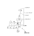
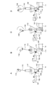
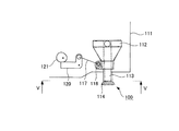
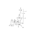
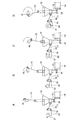
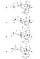
本発明に係る歯車形削り盤の主な実施形態を図1〜6に基づいて説明する。
1B ワーク(円環状)
100 歯車形削り盤
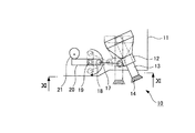
111 ハウジング
111a 開口部
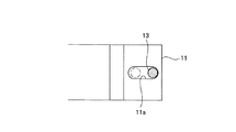
112 カッタヘッド
113 主軸
114 ピニオンカッタ
115 ロッド
116 クランク
117 ロッド
118 アーム
120 レバー
121 カム
Claims (2)
- ピニオンカッタを用いてワークに外歯及び内歯を創成歯切りすることにより歯車を作製する歯車形削り盤であって、
先端に前記ピニオンカッタを取り付けられる主軸と、
先端側から前記主軸の先端側を突出させるように当該主軸を回転可能及び昇降移動可能に支持すると共に、基端側を回動可能に支持されたカッタヘッドと、
前記主軸を回転駆動させる回転駆動手段と、
前記主軸を昇降移動させる昇降移動手段と、
前記主軸が下降移動するときに、前記ワークに接触する加工側位置に前記ピニオンカッタを位置させるように前記カッタヘッドの先端側を揺動移動させると共に当該ピニオンカッタを直線的に下降移動させる一方、前記主軸が上昇移動するときに、前記ワークから離れた退避側位置に前記ピニオンカッタを位置させるように前記カッタヘッドの先端側を揺動移動させると共に当該ピニオンカッタを直線的に上昇移動させるリリービング手段と
を備え、
前記リリービング手段が、
回転可能に設けられて所定のプロファイルのカム面を有するカムと、
一方側が揺動できると共に他方側が前記カムのカム面に常に当接するように回動可能に支持されたレバーと、
一方側が前記カッタヘッドに回動可能に連結されて回動方向一方側と他方側との二位置に位置決め固定できると共に他方側が前記レバーの一方側に対して回動可能に連結された揺動具と
を備えることにより、
前記リリービング手段が、前記ワークに外歯を創成歯切りするときに、前記ピニオンカッタの径方向一方側に前記加工側位置を位置させると共に当該ピニオンカッタを前記ワークの軸心に対して平行に下降移動させる一方、前記ワークに内歯を創成歯切りするときに、前記ピニオンカッタの径方向他方側に前記加工側位置を位置させると共に当該ピニオンカッタを前記ワークの軸心に対して平行に下降移動させるように、前記ピニオンカッタの昇降移動サイクル及び前記ワークの軸心に対する当該ピニオンカッタの移動軌跡の傾斜角度を切り換えるものである
ことを特徴とする歯車形削り盤。 - 請求項1に記載の歯車形削り盤において、
前記揺動具が、
前記カッタヘッドに一方側を回動可能に連結されて回動方向一方側と他方側との二位置に他方側を位置決め固定可能なアームと、
前記アームの他方側に一方側を回動可能に連結されると共に前記レバーの一方側に他方側を回動可能に連結されたロッドと
を備えていることを特徴とする歯車形削り盤。
Priority Applications (7)
| Application Number | Priority Date | Filing Date | Title |
|---|---|---|---|
| JP2010023746A JP5422425B2 (ja) | 2010-02-05 | 2010-02-05 | 歯車形削り盤 |
| US13/504,849 US9108257B2 (en) | 2010-02-05 | 2010-09-09 | Gear shaping machine |
| BR112012010095A BR112012010095A2 (pt) | 2010-02-05 | 2010-09-09 | máquina de conformação de engrenagem |
| PCT/JP2010/065463 WO2011096104A1 (ja) | 2010-02-05 | 2010-09-09 | 歯車形削り盤 |
| EP10845236A EP2532463A1 (en) | 2010-02-05 | 2010-09-09 | Gear shaping machine |
| CN2010800492646A CN102596471A (zh) | 2010-02-05 | 2010-09-09 | 插齿机 |
| TW099131454A TWI421139B (zh) | 2010-02-05 | 2010-09-16 | Gear planer |
Applications Claiming Priority (1)
| Application Number | Priority Date | Filing Date | Title |
|---|---|---|---|
| JP2010023746A JP5422425B2 (ja) | 2010-02-05 | 2010-02-05 | 歯車形削り盤 |
Publications (2)
| Publication Number | Publication Date |
|---|---|
| JP2011161525A JP2011161525A (ja) | 2011-08-25 |
| JP5422425B2 true JP5422425B2 (ja) | 2014-02-19 |
Family
ID=44355126
Family Applications (1)
| Application Number | Title | Priority Date | Filing Date |
|---|---|---|---|
| JP2010023746A Expired - Fee Related JP5422425B2 (ja) | 2010-02-05 | 2010-02-05 | 歯車形削り盤 |
Country Status (7)
| Country | Link |
|---|---|
| US (1) | US9108257B2 (ja) |
| EP (1) | EP2532463A1 (ja) |
| JP (1) | JP5422425B2 (ja) |
| CN (1) | CN102596471A (ja) |
| BR (1) | BR112012010095A2 (ja) |
| TW (1) | TWI421139B (ja) |
| WO (1) | WO2011096104A1 (ja) |
Families Citing this family (9)
| Publication number | Priority date | Publication date | Assignee | Title |
|---|---|---|---|---|
| JP5693685B2 (ja) * | 2013-09-06 | 2015-04-01 | 三菱重工業株式会社 | 歯車加工機械 |
| JP2016034686A (ja) * | 2014-08-04 | 2016-03-17 | 株式会社 神崎高級工機製作所 | 削り盤 |
| CN104841997B (zh) * | 2015-05-20 | 2017-05-10 | 重庆富川古圣机电有限公司 | 插床进让刀机构 |
| CN105728859B (zh) * | 2016-04-11 | 2017-09-22 | 宜昌长机科技有限责任公司 | 一种插齿机刀架体前后摆动导向机构 |
| CN108311761B (zh) * | 2018-03-26 | 2023-07-11 | 宜昌长机科技有限责任公司 | 插齿机让刀系统及方法 |
| CN109648720B (zh) * | 2018-12-19 | 2021-04-13 | 廊坊市鼎鑫联拓工贸有限公司 | 基于保证同一个pdc钻头中所有刀翼加工成型精度的方法 |
| US12350749B2 (en) * | 2020-04-23 | 2025-07-08 | Jtekt Corporation | Gear machining apparatus |
| DE102021002058A1 (de) * | 2021-04-19 | 2022-10-20 | Gleason-Pfauter Maschinenfabrik Gmbh | Verfahren zum Wälzstoßen einer periodischen Struktur, insbesondere einer Verzahnung, und Abhebenocken |
| CN114226877B (zh) * | 2021-12-27 | 2023-06-30 | 机械科学研究总院青岛分院有限公司 | 一种防伤表面的齿轮加工用插齿机床辅助机构 |
Family Cites Families (12)
| Publication number | Priority date | Publication date | Assignee | Title |
|---|---|---|---|---|
| DE1627370A1 (de) * | 1966-03-18 | 1971-07-08 | Tos Czelakovice N P | Anordnung zum Zufuehren und Entfernen eines Werkzeuges gegenueber dem Werkstueck an Abwaelzstossmaschinen |
| DE2148801C3 (de) | 1971-09-30 | 1974-08-29 | Maschinenfabrik Lorenz Ag, 7505 Ettlingen | Abhebeeinrichtung für das Schneidrad einer Zahnradwälzstoßmaschine |
| JPS502298A (ja) | 1973-05-15 | 1975-01-10 | ||
| JPS5015888A (ja) | 1973-06-11 | 1975-02-19 | ||
| CH629133A5 (de) * | 1978-06-02 | 1982-04-15 | Maag Zahnraeder & Maschinen Ag | Vorrichtung zum innenverzahnen grosser werkstuecke an einer zahnradstossmaschine. |
| DE3623125A1 (de) * | 1985-08-13 | 1987-02-26 | Mitsubishi Heavy Ind Ltd | Fuehrungsvorrichtung fuer eine hobel- und stossmaschine zur fertigung von insbesondere schraegverzahnten zahnraedern |
| CH673800A5 (ja) | 1988-03-08 | 1990-04-12 | Maag Zahnraeder & Maschinen Ag | |
| DE10209971A1 (de) * | 2002-03-07 | 2003-10-02 | Liebherr Verzahntech Gmbh | Wälzstoßmaschine und Verfahren zum Betrieb einer Wälzstoßmaschine |
| JP2004154921A (ja) * | 2002-11-08 | 2004-06-03 | Mitsubishi Heavy Ind Ltd | 工作機械 |
| CN2757980Y (zh) * | 2004-12-07 | 2006-02-15 | 宜昌长机科技有限责任公司 | 插齿机的曲柄滑动复合运动装置 |
| JP4247760B2 (ja) * | 2005-11-09 | 2009-04-02 | 株式会社ニイガタマシンテクノ | マシニングセンタによる歯車の加工方法 |
| DE102006052474A1 (de) * | 2006-11-07 | 2008-05-08 | Liebherr-Verzahntechnik Gmbh | Wälzstoßmaschine |
-
2010
- 2010-02-05 JP JP2010023746A patent/JP5422425B2/ja not_active Expired - Fee Related
- 2010-09-09 US US13/504,849 patent/US9108257B2/en not_active Expired - Fee Related
- 2010-09-09 WO PCT/JP2010/065463 patent/WO2011096104A1/ja not_active Ceased
- 2010-09-09 EP EP10845236A patent/EP2532463A1/en not_active Withdrawn
- 2010-09-09 CN CN2010800492646A patent/CN102596471A/zh active Pending
- 2010-09-09 BR BR112012010095A patent/BR112012010095A2/pt not_active IP Right Cessation
- 2010-09-16 TW TW099131454A patent/TWI421139B/zh not_active IP Right Cessation
Also Published As
| Publication number | Publication date |
|---|---|
| US20120301241A1 (en) | 2012-11-29 |
| WO2011096104A1 (ja) | 2011-08-11 |
| BR112012010095A2 (pt) | 2016-05-31 |
| EP2532463A1 (en) | 2012-12-12 |
| TWI421139B (zh) | 2014-01-01 |
| JP2011161525A (ja) | 2011-08-25 |
| TW201134585A (en) | 2011-10-16 |
| US9108257B2 (en) | 2015-08-18 |
| CN102596471A (zh) | 2012-07-18 |
Similar Documents
| Publication | Publication Date | Title |
|---|---|---|
| JP5422425B2 (ja) | 歯車形削り盤 | |
| JP5529125B2 (ja) | 工作機械用の工具交換装置 | |
| TWI661896B (zh) | 工具刀庫之換刀裝置 | |
| TWI454328B (zh) | Tool machine control method and tool machine | |
| US9254543B2 (en) | Machine tool | |
| JP2009125852A (ja) | 工作機械、およびセンサモジュール | |
| JP2018103330A (ja) | 工作機械 | |
| JP5774740B2 (ja) | ツール修整機能を含んだ歯車研削装置 | |
| JP2007062052A5 (ja) | ||
| JP2006062073A5 (ja) | ||
| WO2011067949A1 (ja) | 歯車加工機械 | |
| CN101637833B (zh) | 斜断锯 | |
| JP2011189352A (ja) | 溶接装置 | |
| CN110549017A (zh) | 一种内置式管道切割机的调节装置 | |
| JP5709624B2 (ja) | 歯車形削盤 | |
| CN101642829B (zh) | 斜断锯 | |
| JP2019123028A (ja) | ワーク加工装置 | |
| JPH01301039A (ja) | 工作機械 | |
| JP5244108B2 (ja) | 管切断機械用の回転式スイベル | |
| CN216030207U (zh) | 一种基于数控机床水切割用的角度调整装置 | |
| TWM617577U (zh) | 具換向結構之動力工具 | |
| JP2008173679A (ja) | 溶接トーチの移動装置 | |
| CN111451712B (zh) | 一种叶片用超声波加工设备 | |
| CN101648297B (zh) | 往复切割工具 | |
| JP5288319B2 (ja) | 電動工具 |
Legal Events
| Date | Code | Title | Description |
|---|---|---|---|
| A621 | Written request for application examination |
Free format text: JAPANESE INTERMEDIATE CODE: A621 Effective date: 20120220 |
|
| A131 | Notification of reasons for refusal |
Free format text: JAPANESE INTERMEDIATE CODE: A131 Effective date: 20130528 |
|
| A521 | Request for written amendment filed |
Free format text: JAPANESE INTERMEDIATE CODE: A523 Effective date: 20130710 |
|
| TRDD | Decision of grant or rejection written | ||
| A01 | Written decision to grant a patent or to grant a registration (utility model) |
Free format text: JAPANESE INTERMEDIATE CODE: A01 Effective date: 20131029 |
|
| A61 | First payment of annual fees (during grant procedure) |
Free format text: JAPANESE INTERMEDIATE CODE: A61 Effective date: 20131125 |
|
| R151 | Written notification of patent or utility model registration |
Ref document number: 5422425 Country of ref document: JP Free format text: JAPANESE INTERMEDIATE CODE: R151 |
|
| S111 | Request for change of ownership or part of ownership |
Free format text: JAPANESE INTERMEDIATE CODE: R313111 |
|
| R350 | Written notification of registration of transfer |
Free format text: JAPANESE INTERMEDIATE CODE: R350 |
|
| R250 | Receipt of annual fees |
Free format text: JAPANESE INTERMEDIATE CODE: R250 |
|
| LAPS | Cancellation because of no payment of annual fees |