JP4805598B2 - 雌雄部材組立体 - Google Patents
雌雄部材組立体 Download PDFInfo
- Publication number
- JP4805598B2 JP4805598B2 JP2005117828A JP2005117828A JP4805598B2 JP 4805598 B2 JP4805598 B2 JP 4805598B2 JP 2005117828 A JP2005117828 A JP 2005117828A JP 2005117828 A JP2005117828 A JP 2005117828A JP 4805598 B2 JP4805598 B2 JP 4805598B2
- Authority
- JP
- Japan
- Prior art keywords
- male
- male member
- end opening
- annular groove
- female
- Prior art date
- Legal status (The legal status is an assumption and is not a legal conclusion. Google has not performed a legal analysis and makes no representation as to the accuracy of the status listed.)
- Active
Links
Images


Classifications
-
- F—MECHANICAL ENGINEERING; LIGHTING; HEATING; WEAPONS; BLASTING
- F16—ENGINEERING ELEMENTS AND UNITS; GENERAL MEASURES FOR PRODUCING AND MAINTAINING EFFECTIVE FUNCTIONING OF MACHINES OR INSTALLATIONS; THERMAL INSULATION IN GENERAL
- F16L—PIPES; JOINTS OR FITTINGS FOR PIPES; SUPPORTS FOR PIPES, CABLES OR PROTECTIVE TUBING; MEANS FOR THERMAL INSULATION IN GENERAL
- F16L15/00—Screw-threaded joints; Forms of screw-threads for such joints
- F16L15/006—Screw-threaded joints; Forms of screw-threads for such joints with straight threads
- F16L15/008—Screw-threaded joints; Forms of screw-threads for such joints with straight threads with sealing rings
-
- F—MECHANICAL ENGINEERING; LIGHTING; HEATING; WEAPONS; BLASTING
- F16—ENGINEERING ELEMENTS AND UNITS; GENERAL MEASURES FOR PRODUCING AND MAINTAINING EFFECTIVE FUNCTIONING OF MACHINES OR INSTALLATIONS; THERMAL INSULATION IN GENERAL
- F16J—PISTONS; CYLINDERS; SEALINGS
- F16J15/00—Sealings
- F16J15/02—Sealings between relatively-stationary surfaces
- F16J15/06—Sealings between relatively-stationary surfaces with solid packing compressed between sealing surfaces
- F16J15/061—Sealings between relatively-stationary surfaces with solid packing compressed between sealing surfaces with positioning means
-
- F—MECHANICAL ENGINEERING; LIGHTING; HEATING; WEAPONS; BLASTING
- F16—ENGINEERING ELEMENTS AND UNITS; GENERAL MEASURES FOR PRODUCING AND MAINTAINING EFFECTIVE FUNCTIONING OF MACHINES OR INSTALLATIONS; THERMAL INSULATION IN GENERAL
- F16J—PISTONS; CYLINDERS; SEALINGS
- F16J15/00—Sealings
- F16J15/02—Sealings between relatively-stationary surfaces
- F16J15/06—Sealings between relatively-stationary surfaces with solid packing compressed between sealing surfaces
- F16J15/062—Sealings between relatively-stationary surfaces with solid packing compressed between sealing surfaces characterised by the geometry of the seat
-
- F—MECHANICAL ENGINEERING; LIGHTING; HEATING; WEAPONS; BLASTING
- F16—ENGINEERING ELEMENTS AND UNITS; GENERAL MEASURES FOR PRODUCING AND MAINTAINING EFFECTIVE FUNCTIONING OF MACHINES OR INSTALLATIONS; THERMAL INSULATION IN GENERAL
- F16L—PIPES; JOINTS OR FITTINGS FOR PIPES; SUPPORTS FOR PIPES, CABLES OR PROTECTIVE TUBING; MEANS FOR THERMAL INSULATION IN GENERAL
- F16L21/00—Joints with sleeve or socket
- F16L21/02—Joints with sleeve or socket with elastic sealing rings between pipe and sleeve or between pipe and socket, e.g. with rolling or other prefabricated profiled rings
- F16L21/035—Joints with sleeve or socket with elastic sealing rings between pipe and sleeve or between pipe and socket, e.g. with rolling or other prefabricated profiled rings placed around the spigot end before connection
-
- F—MECHANICAL ENGINEERING; LIGHTING; HEATING; WEAPONS; BLASTING
- F16—ENGINEERING ELEMENTS AND UNITS; GENERAL MEASURES FOR PRODUCING AND MAINTAINING EFFECTIVE FUNCTIONING OF MACHINES OR INSTALLATIONS; THERMAL INSULATION IN GENERAL
- F16L—PIPES; JOINTS OR FITTINGS FOR PIPES; SUPPORTS FOR PIPES, CABLES OR PROTECTIVE TUBING; MEANS FOR THERMAL INSULATION IN GENERAL
- F16L41/00—Branching pipes; Joining pipes to walls
- F16L41/08—Joining pipes to walls or pipes, the joined pipe axis being perpendicular to the plane of the wall or to the axis of another pipe
- F16L41/10—Joining pipes to walls or pipes, the joined pipe axis being perpendicular to the plane of the wall or to the axis of another pipe the extremity of the pipe being screwed into the wall
Description
前端開口から後方へ延びる雄部材受入孔を有し、該雄部材受入孔が該前端開口から後方に向けて所定の長さにわたる前端開口部分と、該前端開口部分よりも小径とされ該前端開口部分に続き後方へ延びる雄部材受入部分とを有してなる雌部材と、
該雄部材受入孔内に、該前端開口から挿入される雄部材であって、該雄部材受入孔内に挿入された状態で該雄部材受入部分の内壁面に隣接する外周面と、該外周面に形成された環状溝とを有する雄部材と、
該雄部材の環状溝に嵌合されて、該雄部材が該雄部材受入孔内に挿入された状態で、該雄部材受入部分の内壁面により押圧変形されて該内壁面と該環状溝との間を密封するシールリングと、
該雄部材が雄部材受入孔内に挿入された状態で該シールリングよりも該雄部材受入孔の前端開口側の位置で、該シールリングに接するようにして該環状溝に嵌合されているバックアップリングと、
を有する雌雄部材組立体における雌部材であって、
該雄部材の該雄部材受入孔への挿入が進むにつれてシールリングが変形されることにより該バックアップリングが該環状溝から半径方向外側に押圧変位されるときに、該バックアップリングが該前端開口部分の内壁面に係合することにより、該環状溝から半径方向外側に外れるのを阻止されるようにしたことを特徴とする雌雄部材組立体における雌部材を提供する。
該前端開口部分の径が、該環状溝に嵌合された該シールリングの外径よりも大とされ、該前端開口部分の内壁面と該雄部材の外周面との間の隙間が、該バックアップリングの半径方向厚さよりも小さくしたものとすることができる。
雄部材受入孔を有する雌部材と、
該雄部材受入孔内に、前端部分から挿入される雄部材であって、該雄部材が雄部材受入孔内に挿入された状態で該雄部材受入孔の内壁面に隣接する外周面と、該外周面に形成された環状溝とを有する雄部材と、
該雄部材の環状溝に嵌合されて、該雄部材が雄部材受入孔内に挿入された状態で、雄部材受入孔の内壁面により押圧変形されて該内壁面と該環状溝との間を密封するシールリングと、
該雄部材における該シールリングよりも後側位置で該シールリングに隣接するようにして該環状溝に嵌合されるバックアップリングと、
を有する雌雄部材組立体における雄部材であって、
前記環状溝が該雄部材の前後方向において間隔をおいて位置する前側環状側壁面及び後側環状側壁面、並びに、該前側環状側壁面及び後側環状側壁面の間に延びる底壁面によって画定されており、
該後側環状側壁面が底壁面から該雄部材の前方に傾斜し、該雄部材の該雄部材受入孔への挿入が進むにつれてシールリングが変形されることにより該バックアップリングが該環状溝から半径方向外側に押圧されるときに、該バックアップリングが該後側環状側壁面に係合して、該環状溝から半径方向外側に外れるのを阻止されるようにしたことを特徴とする雌雄部材組立体における雄部材を提供する。
本発明は、該雄部材を雄型継手部材、該雌部材を雌型継手部材とした管継手に適用することができる。
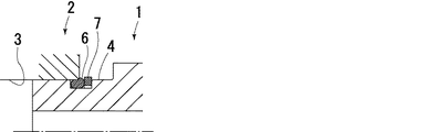
図4は、本発明を適用した管継手10における雄型継手部材12と雌型継手部材14との結合状態を示しており、図5ないし図8は、雄型継手部材12を雌型継手部材14に連結するときのシールリング16及びバックアップリング18の変化を示している。
すなわち、この管継手では、雄型継手部材12の挿入部22に設けられる環状溝24の前側環状側壁面24−1及び後側環状側壁面24−2を、環状溝24の底壁面24−3から当該雄型継手部材の前方に傾斜させている。すなわち、この管継手においては、環状溝24の環状側壁面、特に後側環状側壁面24−2を前方に向けて傾斜させることにより、雄型継手部材12の挿入部22を雌型継手部材14の雄型継手部材受入孔20内に挿入する場合にシールリング16が変形してバックアップリング18を半径方向外方へ押し出そうとしても、該後側環状側壁面24−2がバックアップリング18の動きを抑えて、該バックアップリングが環状溝24から外側に外れるのを阻止するようにしている。
12 雄型継手部材
14 雌型継手部材
16 シールリング
18 バックアップリング
20 雄型継手部材受入孔
20−1 前端開口部分
20−2 雄部材受入部分
20−3 内壁面
22 挿入部
22−1 挿入部の外周面
24 環状溝
Claims (3)
- 前端開口から後方へ延びる雄部材受入孔を有し、該雄部材受入孔が該前端開口から後方に向けて所定の長さにわたる前端開口部分と、該前端開口部分よりも小径とされ該前端開口部分に続き後方へ延びる雄部材受入部分とを有してなる雌部材と、
該雄部材受入孔内に、該前端開口から挿入される雄部材であって、該雄部材受入孔内に挿入された状態で該雄部材受入部分の内壁面に隣接する外周面と、該外周面に形成された環状溝とを有する雄部材と、
該雄部材の環状溝に嵌合されたシールリングであって、該雄部材受入部分の内径よりも大きな外径を有し、該雄部材が該雄部材受入孔内に挿入されると、該雄部材受入部分の内壁面により押圧変形されて該内壁面と該環状溝との間を密封するシールリングと、
該シールリングよりも該雄部材受入孔の前端開口側の位置で、該シールリングに接するようにして該環状溝に嵌合されたバックアップリングであって、スプリットリングとされ雄部材受入部分の内径よりも小径とされたバックアップリングと、
を有する雌雄部材組立体における雌部材であって、
該雄部材受入部分と該前端開口部分との間が該前端開口の内壁面から該雄部材受入部分の内壁面にいたるテーパ面とされており、該前端開口部分の内壁面と該雄部材の外周面との間の間隔が、該バックアップリングの半径方向厚さよりも小さくされており、該雄部材が前記テーパ面を通って前記雄部材受入部分内に圧入されるときに、シールリングが変形されることにより該バックアップリングが該環状溝から半径方向外側に押圧変位され、該バックアップリングが該前端開口部分の内壁面に係合することにより、該環状溝から半径方向外側に外れるのを阻止されるようにしたことを特徴とする雌雄部材組立体における雌部材。 - 該前端開口部分の内周面が、該環状溝に嵌合された該シールリングよりも大径とされている請求項1に記載の雌部材。
- 該雌雄部材組立体が管継手とされ、該管継手の雌型継手部材とされる請求項1又は2のいずれかに記載の雌部材。
Priority Applications (6)
| Application Number | Priority Date | Filing Date | Title |
|---|---|---|---|
| JP2005117828A JP4805598B2 (ja) | 2005-04-15 | 2005-04-15 | 雌雄部材組立体 |
| US11/918,479 US7641239B2 (en) | 2005-04-15 | 2006-04-11 | Assembly of male and female members |
| PCT/JP2006/307643 WO2006112301A1 (ja) | 2005-04-15 | 2006-04-11 | 雌雄部材組立体 |
| EP06731590A EP1870623B1 (en) | 2005-04-15 | 2006-04-11 | Assembly of male and female members |
| CN2006800168788A CN101175939B (zh) | 2005-04-15 | 2006-04-11 | 阴阳部件组装体及该组装体中的阴部件 |
| US12/620,858 US20100059997A1 (en) | 2005-04-15 | 2009-11-18 | Assembly of male and female members |
Applications Claiming Priority (1)
| Application Number | Priority Date | Filing Date | Title |
|---|---|---|---|
| JP2005117828A JP4805598B2 (ja) | 2005-04-15 | 2005-04-15 | 雌雄部材組立体 |
Publications (3)
| Publication Number | Publication Date |
|---|---|
| JP2006300082A JP2006300082A (ja) | 2006-11-02 |
| JP2006300082A5 JP2006300082A5 (ja) | 2007-11-29 |
| JP4805598B2 true JP4805598B2 (ja) | 2011-11-02 |
Family
ID=37115026
Family Applications (1)
| Application Number | Title | Priority Date | Filing Date |
|---|---|---|---|
| JP2005117828A Active JP4805598B2 (ja) | 2005-04-15 | 2005-04-15 | 雌雄部材組立体 |
Country Status (5)
| Country | Link |
|---|---|
| US (2) | US7641239B2 (ja) |
| EP (1) | EP1870623B1 (ja) |
| JP (1) | JP4805598B2 (ja) |
| CN (1) | CN101175939B (ja) |
| WO (1) | WO2006112301A1 (ja) |
Families Citing this family (12)
| Publication number | Priority date | Publication date | Assignee | Title |
|---|---|---|---|---|
| JP4901686B2 (ja) * | 2007-10-12 | 2012-03-21 | 株式会社酒井製作所 | 軸継ぎ手 |
| US20100051528A1 (en) * | 2008-08-26 | 2010-03-04 | Clark Filter, Inc. | Seal Improvement for Lube Filter |
| JP5965580B2 (ja) * | 2010-12-22 | 2016-08-10 | 株式会社ダイゾー | 容器口部のシール構造 |
| CN103328347B (zh) | 2010-12-22 | 2015-05-27 | 株式会社大造 | 阀总成以及使用它的空气溶胶容器、空气溶胶制品及其制造方法 |
| JP5374559B2 (ja) * | 2011-09-20 | 2013-12-25 | 本田技研工業株式会社 | 封止構造体 |
| JP6081095B2 (ja) * | 2012-07-17 | 2017-02-15 | Nok株式会社 | シール構造 |
| DE102012108566B4 (de) * | 2012-09-13 | 2016-01-28 | Dionex Softron Gmbh | Steckereinheit und Verbindungseinrichtung für Flüssigkeit führende Komponenten, insbesondere für die Hochleistungsflüssigkeitschromatographie |
| DE102013222508B4 (de) * | 2013-11-06 | 2023-07-27 | Robert Bosch Gmbh | Ventil zum Zumessen von unter Hochdruck stehendem Fluid |
| JP6643131B2 (ja) * | 2016-02-12 | 2020-02-12 | Kyb株式会社 | 変速機及び変速機を備えた駆動装置 |
| WO2018195090A1 (en) | 2017-04-20 | 2018-10-25 | Olivia Garden International Inc. | Hair brush with ejection system |
| CN109373070B (zh) * | 2018-10-22 | 2024-02-09 | 苏州德森福汽车科技有限公司 | 一种联接器的组装结构 |
| CN114135731B (zh) * | 2021-11-30 | 2023-09-29 | 西北工业大学上海闵行协同创新中心 | 一种管接头环榫确定方法及带环榫的管接头 |
Family Cites Families (33)
| Publication number | Priority date | Publication date | Assignee | Title |
|---|---|---|---|---|
| US3273919A (en) * | 1965-03-16 | 1966-09-20 | Sloan Valve Co | Adjustable plumbing fittings |
| FR1557910A (ja) * | 1968-01-09 | 1969-02-21 | ||
| US4027816A (en) * | 1975-04-18 | 1977-06-07 | Bowen Tools, Inc. | Seal assembly |
| US4402773A (en) * | 1977-09-15 | 1983-09-06 | Smith International, Inc. | Remote automatic make-up stab-in sealing system |
| DE2911156C2 (de) * | 1979-03-22 | 1981-10-01 | Martin Merkel Kg, 2102 Hamburg | Doppeltwirkende Dichtungsanordnung |
| US4548431A (en) * | 1981-12-17 | 1985-10-22 | Hughes Tool Company - Usa | Tool joint with internal/external make-up shoulders |
| US4733890A (en) * | 1984-07-09 | 1988-03-29 | Stratoflex, Inc. | Formed fluid coupling apparatus |
| US5004273A (en) * | 1989-06-26 | 1991-04-02 | Baugh Benton F | Tieback thread with angular freedom |
| JPH04127460U (ja) * | 1991-05-13 | 1992-11-19 | 日本鋼管株式会社 | シール用oリングの溝 |
| US5364131A (en) * | 1993-02-01 | 1994-11-15 | Ford Motor Company | Quick-connect tubular coupling |
| CN2186840Y (zh) * | 1994-03-30 | 1995-01-04 | 梁启海 | 光管快速接头 |
| CN2247752Y (zh) * | 1996-04-12 | 1997-02-19 | 杜茂林 | 可调密封间隙的管材接头 |
| JP3532714B2 (ja) * | 1996-06-21 | 2004-05-31 | Nok株式会社 | シール装置 |
| JPH11304002A (ja) * | 1998-04-15 | 1999-11-05 | Kawamoto Pump Mfg Co Ltd | Oリングを用いたシール構造 |
| JP3543617B2 (ja) | 1998-04-30 | 2004-07-14 | Nok株式会社 | 密封装置 |
| US6443502B1 (en) * | 1999-04-22 | 2002-09-03 | Denso Corporation | Leakage restriction device for refrigeration cycle |
| US6173968B1 (en) * | 1999-04-27 | 2001-01-16 | Trw Inc. | Sealing ring assembly |
| JP2001124277A (ja) * | 1999-10-29 | 2001-05-11 | Nitto Kohki Co Ltd | 管継手 |
| IT1318179B1 (it) * | 2000-07-17 | 2003-07-23 | Dalmine Spa | Giunzione filettata integrale per tubi. |
| IT1318753B1 (it) * | 2000-08-09 | 2003-09-10 | Dalmine Spa | Giunzione filettata integrale a profilo continuo pr tubi |
| JP2002106763A (ja) | 2000-09-29 | 2002-04-10 | Toto Ltd | フラッシュバルブ用差込継手 |
| KR200232262Y1 (ko) * | 2001-02-19 | 2001-09-25 | 진보정밀공업 주식회사 | 튜브 커플러 |
| US20020163193A1 (en) * | 2001-03-30 | 2002-11-07 | Abuellel Adel A. | Pipe coupling |
| JP4184066B2 (ja) * | 2002-12-20 | 2008-11-19 | 株式会社ケンウッド | 部材間の密着構造 |
| WO2004061353A1 (ja) * | 2002-12-27 | 2004-07-22 | Nok Corporation | 接続装置 |
| JP4096832B2 (ja) * | 2003-07-22 | 2008-06-04 | 株式会社デンソー | 冷凍サイクル用配管継手 |
| JP4030478B2 (ja) * | 2003-07-29 | 2008-01-09 | 株式会社デンソー | 冷凍サイクル用配管継手 |
| US20050116468A1 (en) * | 2003-11-28 | 2005-06-02 | Otten Gregory K. | Threaded connectors for axial alignment of tubular components, and method of installing pipe sections employing such connectors |
| US7249789B2 (en) * | 2004-10-14 | 2007-07-31 | Johnson Screens, Inc. | Water well casing |
| AU2005302599B2 (en) * | 2004-10-29 | 2009-02-12 | The Gates Corporation | Quick connect coupling |
| US7527304B2 (en) * | 2004-12-30 | 2009-05-05 | Hydril Llc | Floating wedge thread for tubular connection |
| US7533907B2 (en) * | 2005-03-11 | 2009-05-19 | The Gates Corporation Ip Law Dept. | Pressure activated disconnect lock coupling |
| US7780202B2 (en) * | 2007-09-05 | 2010-08-24 | Grant Prideco, Lp | Oilfield tubular connection with increased compression capacity |
-
2005
- 2005-04-15 JP JP2005117828A patent/JP4805598B2/ja active Active
-
2006
- 2006-04-11 US US11/918,479 patent/US7641239B2/en active Active
- 2006-04-11 CN CN2006800168788A patent/CN101175939B/zh active Active
- 2006-04-11 WO PCT/JP2006/307643 patent/WO2006112301A1/ja active Application Filing
- 2006-04-11 EP EP06731590A patent/EP1870623B1/en active Active
-
2009
- 2009-11-18 US US12/620,858 patent/US20100059997A1/en not_active Abandoned
Also Published As
| Publication number | Publication date |
|---|---|
| EP1870623A1 (en) | 2007-12-26 |
| US20100059997A1 (en) | 2010-03-11 |
| US20090026762A1 (en) | 2009-01-29 |
| US7641239B2 (en) | 2010-01-05 |
| EP1870623A4 (en) | 2010-07-21 |
| CN101175939A (zh) | 2008-05-07 |
| WO2006112301A1 (ja) | 2006-10-26 |
| EP1870623B1 (en) | 2012-02-01 |
| JP2006300082A (ja) | 2006-11-02 |
| CN101175939B (zh) | 2010-09-29 |
Similar Documents
| Publication | Publication Date | Title |
|---|---|---|
| JP4805598B2 (ja) | 雌雄部材組立体 | |
| US8720952B2 (en) | Connector | |
| JP3882169B2 (ja) | カップリング組立体 | |
| US6869109B2 (en) | Pipe joint | |
| JP4845635B2 (ja) | 離脱防止管継手 | |
| KR100989423B1 (ko) | 실링부재 및 이러한 실링부재가 적용된 관체 | |
| JP2017180472A (ja) | 管継手および管の接合方法 | |
| US5127682A (en) | Joint | |
| TWI628386B (zh) | 管子接頭、脫離防止構件、及管子接合方法 | |
| JP2008240771A (ja) | フレキシブル管用継手のシール方法およびシール構造 | |
| JP5455381B2 (ja) | シール材 | |
| JP2006118712A (ja) | 結合インジケータ付カップリングアセンブリ | |
| JP2008089095A (ja) | 管継手およびそれに用いられるバックアップリング | |
| JP5455383B2 (ja) | 管継手 | |
| JP6735124B2 (ja) | 管継手および離脱防止部材 | |
| JP5003952B2 (ja) | 管継手 | |
| WO2011043113A1 (ja) | 離脱防止機能付きシール材および離脱防止管継手 | |
| JP4982321B2 (ja) | クイックコネクタ | |
| JP6764668B2 (ja) | 管継手および管の接合方法 | |
| JP4213055B2 (ja) | 配管接続部のシール構造 | |
| JP2758098B2 (ja) | 離脱防止管継手 | |
| JP2006307923A (ja) | 管継手 | |
| JP3702671B2 (ja) | クイックコネクター | |
| JP2005337269A (ja) | 離脱防止管継手 | |
| JP5377095B2 (ja) | 管継手構造および接続管 |
Legal Events
| Date | Code | Title | Description |
|---|---|---|---|
| A621 | Written request for application examination |
Free format text: JAPANESE INTERMEDIATE CODE: A621 Effective date: 20060829 |
|
| A521 | Request for written amendment filed |
Free format text: JAPANESE INTERMEDIATE CODE: A523 Effective date: 20071010 |
|
| A131 | Notification of reasons for refusal |
Free format text: JAPANESE INTERMEDIATE CODE: A131 Effective date: 20090812 |
|
| A521 | Request for written amendment filed |
Free format text: JAPANESE INTERMEDIATE CODE: A523 Effective date: 20091008 |
|
| A131 | Notification of reasons for refusal |
Free format text: JAPANESE INTERMEDIATE CODE: A131 Effective date: 20100216 |
|
| A131 | Notification of reasons for refusal |
Free format text: JAPANESE INTERMEDIATE CODE: A131 Effective date: 20100831 |
|
| A521 | Request for written amendment filed |
Free format text: JAPANESE INTERMEDIATE CODE: A523 Effective date: 20101101 |
|
| A131 | Notification of reasons for refusal |
Free format text: JAPANESE INTERMEDIATE CODE: A131 Effective date: 20110301 |
|
| A521 | Request for written amendment filed |
Free format text: JAPANESE INTERMEDIATE CODE: A523 Effective date: 20110428 |
|
| TRDD | Decision of grant or rejection written | ||
| A01 | Written decision to grant a patent or to grant a registration (utility model) |
Free format text: JAPANESE INTERMEDIATE CODE: A01 Effective date: 20110802 |
|
| A01 | Written decision to grant a patent or to grant a registration (utility model) |
Free format text: JAPANESE INTERMEDIATE CODE: A01 |
|
| A61 | First payment of annual fees (during grant procedure) |
Free format text: JAPANESE INTERMEDIATE CODE: A61 Effective date: 20110811 |
|
| R150 | Certificate of patent or registration of utility model |
Ref document number: 4805598 Country of ref document: JP Free format text: JAPANESE INTERMEDIATE CODE: R150 Free format text: JAPANESE INTERMEDIATE CODE: R150 |
|
| FPAY | Renewal fee payment (event date is renewal date of database) |
Free format text: PAYMENT UNTIL: 20140819 Year of fee payment: 3 |
|
| R250 | Receipt of annual fees |
Free format text: JAPANESE INTERMEDIATE CODE: R250 |
|
| R250 | Receipt of annual fees |
Free format text: JAPANESE INTERMEDIATE CODE: R250 |
|
| R250 | Receipt of annual fees |
Free format text: JAPANESE INTERMEDIATE CODE: R250 |
|
| R250 | Receipt of annual fees |
Free format text: JAPANESE INTERMEDIATE CODE: R250 |
|
| R250 | Receipt of annual fees |
Free format text: JAPANESE INTERMEDIATE CODE: R250 |
|
| R250 | Receipt of annual fees |
Free format text: JAPANESE INTERMEDIATE CODE: R250 |
|
| R250 | Receipt of annual fees |
Free format text: JAPANESE INTERMEDIATE CODE: R250 |
|
| R250 | Receipt of annual fees |
Free format text: JAPANESE INTERMEDIATE CODE: R250 |
|
| R250 | Receipt of annual fees |
Free format text: JAPANESE INTERMEDIATE CODE: R250 |
|
| R250 | Receipt of annual fees |
Free format text: JAPANESE INTERMEDIATE CODE: R250 |