EP1870623B1 - Assembly of male and female members - Google Patents
Assembly of male and female members Download PDFInfo
- Publication number
- EP1870623B1 EP1870623B1 EP06731590A EP06731590A EP1870623B1 EP 1870623 B1 EP1870623 B1 EP 1870623B1 EP 06731590 A EP06731590 A EP 06731590A EP 06731590 A EP06731590 A EP 06731590A EP 1870623 B1 EP1870623 B1 EP 1870623B1
- Authority
- EP
- European Patent Office
- Prior art keywords
- male member
- male
- end opening
- annular groove
- wall surface
- Prior art date
- Legal status (The legal status is an assumption and is not a legal conclusion. Google has not performed a legal analysis and makes no representation as to the accuracy of the status listed.)
- Active
Links
Images


Classifications
-
- F—MECHANICAL ENGINEERING; LIGHTING; HEATING; WEAPONS; BLASTING
- F16—ENGINEERING ELEMENTS AND UNITS; GENERAL MEASURES FOR PRODUCING AND MAINTAINING EFFECTIVE FUNCTIONING OF MACHINES OR INSTALLATIONS; THERMAL INSULATION IN GENERAL
- F16L—PIPES; JOINTS OR FITTINGS FOR PIPES; SUPPORTS FOR PIPES, CABLES OR PROTECTIVE TUBING; MEANS FOR THERMAL INSULATION IN GENERAL
- F16L15/00—Screw-threaded joints; Forms of screw-threads for such joints
- F16L15/006—Screw-threaded joints; Forms of screw-threads for such joints with straight threads
- F16L15/008—Screw-threaded joints; Forms of screw-threads for such joints with straight threads with sealing rings
-
- F—MECHANICAL ENGINEERING; LIGHTING; HEATING; WEAPONS; BLASTING
- F16—ENGINEERING ELEMENTS AND UNITS; GENERAL MEASURES FOR PRODUCING AND MAINTAINING EFFECTIVE FUNCTIONING OF MACHINES OR INSTALLATIONS; THERMAL INSULATION IN GENERAL
- F16J—PISTONS; CYLINDERS; SEALINGS
- F16J15/00—Sealings
- F16J15/02—Sealings between relatively-stationary surfaces
- F16J15/06—Sealings between relatively-stationary surfaces with solid packing compressed between sealing surfaces
- F16J15/061—Sealings between relatively-stationary surfaces with solid packing compressed between sealing surfaces with positioning means
-
- F—MECHANICAL ENGINEERING; LIGHTING; HEATING; WEAPONS; BLASTING
- F16—ENGINEERING ELEMENTS AND UNITS; GENERAL MEASURES FOR PRODUCING AND MAINTAINING EFFECTIVE FUNCTIONING OF MACHINES OR INSTALLATIONS; THERMAL INSULATION IN GENERAL
- F16J—PISTONS; CYLINDERS; SEALINGS
- F16J15/00—Sealings
- F16J15/02—Sealings between relatively-stationary surfaces
- F16J15/06—Sealings between relatively-stationary surfaces with solid packing compressed between sealing surfaces
- F16J15/062—Sealings between relatively-stationary surfaces with solid packing compressed between sealing surfaces characterised by the geometry of the seat
-
- F—MECHANICAL ENGINEERING; LIGHTING; HEATING; WEAPONS; BLASTING
- F16—ENGINEERING ELEMENTS AND UNITS; GENERAL MEASURES FOR PRODUCING AND MAINTAINING EFFECTIVE FUNCTIONING OF MACHINES OR INSTALLATIONS; THERMAL INSULATION IN GENERAL
- F16L—PIPES; JOINTS OR FITTINGS FOR PIPES; SUPPORTS FOR PIPES, CABLES OR PROTECTIVE TUBING; MEANS FOR THERMAL INSULATION IN GENERAL
- F16L21/00—Joints with sleeve or socket
- F16L21/02—Joints with sleeve or socket with elastic sealing rings between pipe and sleeve or between pipe and socket, e.g. with rolling or other prefabricated profiled rings
- F16L21/035—Joints with sleeve or socket with elastic sealing rings between pipe and sleeve or between pipe and socket, e.g. with rolling or other prefabricated profiled rings placed around the spigot end before connection
-
- F—MECHANICAL ENGINEERING; LIGHTING; HEATING; WEAPONS; BLASTING
- F16—ENGINEERING ELEMENTS AND UNITS; GENERAL MEASURES FOR PRODUCING AND MAINTAINING EFFECTIVE FUNCTIONING OF MACHINES OR INSTALLATIONS; THERMAL INSULATION IN GENERAL
- F16L—PIPES; JOINTS OR FITTINGS FOR PIPES; SUPPORTS FOR PIPES, CABLES OR PROTECTIVE TUBING; MEANS FOR THERMAL INSULATION IN GENERAL
- F16L41/00—Branching pipes; Joining pipes to walls
- F16L41/08—Joining pipes to walls or pipes, the joined pipe axis being perpendicular to the plane of the wall or to the axis of another pipe
- F16L41/10—Joining pipes to walls or pipes, the joined pipe axis being perpendicular to the plane of the wall or to the axis of another pipe the extremity of the pipe being screwed into the wall
Definitions
- the present invention relates to a seal that is set between a male member subjected to a high-pressure fluid and a female member connected to the male member such as a male coupling member and a female coupling member of a pipe coupling used, for example, in a high-pressure fluid circuit.
- a seal ring and a backup ring that supports the seal ring are, generally, set between a male coupling member and a female coupling member to prevent leakage of a high-pressure fluid from therebetween in a state where the male coupling member has been inserted into and connected to the female coupling member (see Japanese Patent Application Publication No. 2005-42815 and corresponding US 2005/0023828A1 ).
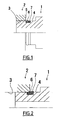
- Figs. 1 to 3 show an example of a way in which a male coupling member 1 is inserted into a female coupling member 2 in a conventional pipe coupling.
- the male coupling member 1 has an insert part 4 having substantially the same diameter as that of a male member reception hole 3 of the female coupling member 2.
- the insert part 4 has an annular groove 5 on the outer peripheral surface thereof.
- An elastic seal ring 6 and a backup ring 7 are set in the annular groove 5.
- the seal ring 6 is formed of a rubber or other material.
- the backup ring 7 is formed of a plastic or other material to have a relatively high rigidity.
- the seal ring 6, however, is deformed by engagement with the end opening section of the male member reception hole 3 of the female coupling member 2 from the point of time when the insert part 4 of the male coupling member 1 begins to be inserted into the male member reception hole 3 of the female coupling member 2, and this causes the backup ring 7 to be pressed radially outward.
- the backup ring 7 is a split ring (i.e. a ring having a split, or cut, in a part thereof) to allow it to be inserted into the annular groove 5.
- Document US 4 027 816 A discloses an improved seal assembly for sealing between relatively movable members in an oil tool or the like including a split protective ring held in position by a seal ring having a circumferential locking shoulder.
- an object of the present invention is to make it possible to readily and reliably install a seal ring and a backup ring that are provided to effect sealing between a male member such as a male coupling member that is subjected to a high-pressure fluid and a female member such as a female coupling member that is connected to the male member.
- the present invention provides a male and female member assembly according to claim 1.
- the seal ring is inserted into the front end opening section without substantially encountering resistance and hence without being deformed. Even when the seal ring is inserted further rearward (inward) from the front end opening section and deformed to press the backup ring to come out of the annular groove, the inner wall surface of the front end opening section engages the backup ring. Thus, the backup ring can be prevented from becoming dislodged from the annular groove.
- the backup ring even if the backup ring is pressed to come out of the annular groove by deformation of the seal ring, the backup ring thus pressed is received in the front end opening section of the male member reception hole and retained by the inner wall surface of the front end opening section, thereby being prevented from becoming dislodged from the annular groove.
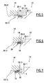
- Fig. 4 shows a pipe coupling 10 to which the present invention is applied in a state where a male coupling member 12 and a female coupling member 14 are connected to each other.
- Figs. 5 to 8 show the way in which a seal ring 16 and a backup ring 18 change when the male coupling member 12 is connected to the female coupling member 14.
- the male coupling member 12 has an insert part 22 of substantially the same diameter as that of a male member reception hole 20 in the same way as in the foregoing conventional pipe coupling.
- the insert part 22 has an annular groove 24 formed on the outer peripheral surface 22-1 thereof.
- the seal ring 16 and the backup ring 18 are set in the annular groove 24.
- the female coupling member 14 has a front end opening section 20-1 extending rearward over a predetermined length from the front end opening of the male member reception hole 20.
- the front end opening section 20-1 has a diameter larger than that of a male member reception section 20-2 of the male member reception hole 20 that follows the front end opening section 20-1.
- the diameter of the front end opening section 20-1 is set slightly larger than the outer diameter of the seal ring 16 as fitted in the annular groove 24 of the insert part 22 of the male coupling member 12 and undeformed.
- the front end opening section 20-1 has a predetermined axial length to allow the backup ring 18 to engage the inner wall surface 20-3 of the front end opening section 20-1 as the backup ring 18 is pressed radially outward from the annular groove 24 by the seal ring 16 deformed by engagement with the inner wall surface of the male member reception hole 20 when the male coupling member 12 has begun to be inserted into the male member reception hole 20, thereby preventing the backup ring 18 from coming out radially outward from the annular groove 24.
- the greater part of the backup ring 18 is located within the front end opening section 20-1 as the seal ring 16 set in the annular groove 24 of the male coupling member 12 begins to be forced into the male member reception section 20-2 of the male member reception hole 20.
- the diameter of the front end opening section 20-1 is set larger than the outer diameter of the seal ring 16 as fitted in the annular groove 24 as has been stated above.
- the spacing s ( Fig. 6 ) between the inner wall surface 20-3 of the front end opening section 20-1 and the outer peripheral surface of the insert part 22 of the male coupling member 12 is set smaller than the radial thickness t ( Fig. 7 ) of the backup ring 18.
- a rearwardly tapered surface is provided to connect between the front end opening section 20-1 and the male member reception section 20-2 that follows it, thereby facilitating the entry of the seal ring 16 and the backup ring 18 into the male member reception section 20-2.
- the backup ring 18 is rigid. Therefore, the outer diameter of the backup ring 18 as fitted in the annular groove 24 is set smaller than the diameter of the male member reception section 20-2 to allow the backup ring 18 to be inserted into the male member reception section 20-2.
- Figs. 9 to 11 show a pipe coupling not forming part of the present invention.
- the annular groove 24 provided on the insert part 22 of the male coupling member 12 has a front annular side wall surface 24-1 and a rear annular side wall surface 24-2 that are inclined forward of the male coupling member 12 from a bottom wall surface 24-3 of the annular groove 24.
- the annular side wall surfaces of the annular groove 24, particularly the rear annular side wall surface 24-2 are inclined forward, whereby when the insert part 22 of the male coupling member 12 is inserted into the male member reception hole 20 of the female coupling member 14, even if the seal ring 16 is deformed so as to press the backup ring 18 radially outward, the rear annular side wall surface 24-2 restrains the radially outward movement of the backup ring 18 and thus prevents the backup ring 18 from becoming dislodged outward from the annular groove 24.
Abstract
Description
- The present invention relates to a seal that is set between a male member subjected to a high-pressure fluid and a female member connected to the male member such as a male coupling member and a female coupling member of a pipe coupling used, for example, in a high-pressure fluid circuit.
- In a pipe coupling used in a high-pressure fluid circuit, a seal ring and a backup ring that supports the seal ring are, generally, set between a male coupling member and a female coupling member to prevent leakage of a high-pressure fluid from therebetween in a state where the male coupling member has been inserted into and connected to the female coupling member (see Japanese Patent Application Publication No.
2005-42815 US 2005/0023828A1 ). - There is a method of setting a seal ring and a backup ring wherein after the seal ring and the backup ring have been fitted in an annular groove formed on the outer peripheral surface of a male coupling member, the male coupling member is inserted into and connected to a female coupling member. This method suffers, however, from the following problem.
-
Figs. 1 to 3 show an example of a way in which amale coupling member 1 is inserted into afemale coupling member 2 in a conventional pipe coupling. Themale coupling member 1 has aninsert part 4 having substantially the same diameter as that of a malemember reception hole 3 of thefemale coupling member 2. Theinsert part 4 has an annular groove 5 on the outer peripheral surface thereof. Anelastic seal ring 6 and abackup ring 7 are set in the annular groove 5. Theseal ring 6 is formed of a rubber or other material. Thebackup ring 7 is formed of a plastic or other material to have a relatively high rigidity. When theinsert part 4 of themale coupling member 1 is inserted into the malemember reception hole 3 of thefemale coupling member 2, theseal ring 6 is pressed between the inner wall surface of the malemember reception hole 3 and the annular groove 5 and thus elastically deformed to effect sealing. - The
seal ring 6, however, is deformed by engagement with the end opening section of the malemember reception hole 3 of thefemale coupling member 2 from the point of time when theinsert part 4 of themale coupling member 1 begins to be inserted into the malemember reception hole 3 of thefemale coupling member 2, and this causes thebackup ring 7 to be pressed radially outward. Thebackup ring 7 is a split ring (i.e. a ring having a split, or cut, in a part thereof) to allow it to be inserted into the annular groove 5. Accordingly, if a radially outward pressure is applied to thebackup ring 7 by the deformation of theseal ring 6, thebackup ring 7 expands radially outward and may become dislodged outward from the annular groove 5 under certain circumstances before being inserted into the male member reception hole 3 (Figs. 2 and3 ).
DocumentUS 4 027 816 A discloses an improved seal assembly for sealing between relatively movable members in an oil tool or the like including a split protective ring held in position by a seal ring having a circumferential locking shoulder. - The present invention has been made in view of the above-described circumstances. Accordingly, an object of the present invention is to make it possible to readily and reliably install a seal ring and a backup ring that are provided to effect sealing between a male member such as a male coupling member that is subjected to a high-pressure fluid and a female member such as a female coupling member that is connected to the male member.
- That is, the present invention provides a male and female member assembly according to
claim 1. - That is, in this male and female member assembly, even if the backup ring is pressed to come out of the annular groove by deformation of the seal ring, the backup ring thus pressed is received in the front end opening section of the male member reception hole and retained by the inner wall surface of the front end opening section, thereby being prevented from becoming dislodged from the annular groove.
- Other features of the male and female member assembly according to the invention are present in the dependent claims.
- With the above-described arrangement, the seal ring is inserted into the front end opening section without substantially encountering resistance and hence without being deformed. Even when the seal ring is inserted further rearward (inward) from the front end opening section and deformed to press the backup ring to come out of the annular groove, the inner wall surface of the front end opening section engages the backup ring. Thus, the backup ring can be prevented from becoming dislodged from the annular groove.
- In the male and female member assembly according to the present invention, even if the backup ring is pressed to come out of the annular groove by deformation of the seal ring, the backup ring thus pressed is received in the front end opening section of the male member reception hole and retained by the inner wall surface of the front end opening section, thereby being prevented from becoming dislodged from the annular groove.
-
- [
Fig. 1] Fig. 1 is a fragmentary sectional view of a conventional pipe coupling, showing a state where a male coupling member has begun to be inserted into a female coupling member. - [
Fig. 2] Fig. 2 is a fragmentary sectional view of the pipe coupling inFig. 1 , showing a state where the male coupling member has been further inserted into the female coupling member. - [
Fig. 3] Fig. 3 is a fragmentary sectional view of the pipe coupling inFig. 1 , showing a state where the male coupling member has been even further inserted into the female coupling member (further than the position shown inFig. 2 ). - [
Fig. 4] Fig. 4 is a fragmentary sectional view of a pipe coupling according to the present invention. - [
Fig. 5] Fig. 5 is a fragmentary sectional view of the pipe coupling inFig. 4 , showing a state where a male coupling member has begun to be inserted into a female coupling member. - [
Fig. 6] Fig. 6 is a fragmentary sectional view showing a state where the male coupling member has been inserted into the female coupling member further than the position shown inFig. 5 . - [
Fig. 7] Fig. 7 is a fragmentary sectional view showing a state where the male coupling member has been inserted into the female coupling member further than the position shown inFig. 6 . - [
Fig. 8] Fig. 8 is a fragmentary sectional view of the pipe coupling inFig. 4 , showing a state where the insertion of the male coupling member into the female coupling member has been completed. - [
Fig. 9] Fig. 9 is a fragmentary sectional view of a pipe coupling not forming part of the present invention, showing a state where a male coupling member has begun to be inserted into a female coupling member. - [
Fig. 10] Fig. 10 is a fragmentary sectional view showing a state where the male coupling member has been inserted into the female coupling member further than the position shown inFig. 9 . - [
Fig. 11] Fig. 11 is a fragmentary sectional view showing a state where the male coupling member has been inserted into the female coupling member further than the position shown inFig. 10 . -
- 10: pipe coupling
- 12: male coupling member
- 14: female coupling member
- 16: seal ring
- 18: backup ring
- 20: male member reception hole
- 20-1: front end opening section
- 20-2: male member reception section
- 20-3: inner wall surface
- 22: insert part
- 22-1: outer peripheral surface of insert part
- 24: annular groove
- Embodiments of the present invention will be described below with reference to the accompanying drawings.
Fig. 4 shows apipe coupling 10 to which the present invention is applied in a state where amale coupling member 12 and afemale coupling member 14 are connected to each other.Figs. 5 to 8 show the way in which aseal ring 16 and abackup ring 18 change when themale coupling member 12 is connected to thefemale coupling member 14. - The
male coupling member 12 has aninsert part 22 of substantially the same diameter as that of a malemember reception hole 20 in the same way as in the foregoing conventional pipe coupling. Theinsert part 22 has anannular groove 24 formed on the outer peripheral surface 22-1 thereof. Theseal ring 16 and thebackup ring 18 are set in theannular groove 24. - The
female coupling member 14 has a front end opening section 20-1 extending rearward over a predetermined length from the front end opening of the malemember reception hole 20. The front end opening section 20-1 has a diameter larger than that of a male member reception section 20-2 of the malemember reception hole 20 that follows the front end opening section 20-1. - In the illustrated example, the diameter of the front end opening section 20-1 is set slightly larger than the outer diameter of the
seal ring 16 as fitted in theannular groove 24 of theinsert part 22 of themale coupling member 12 and undeformed. - The front end opening section 20-1 has a predetermined axial length to allow the
backup ring 18 to engage the inner wall surface 20-3 of the front end opening section 20-1 as thebackup ring 18 is pressed radially outward from theannular groove 24 by theseal ring 16 deformed by engagement with the inner wall surface of the malemember reception hole 20 when themale coupling member 12 has begun to be inserted into the malemember reception hole 20, thereby preventing thebackup ring 18 from coming out radially outward from theannular groove 24. In the illustrated example, the greater part of thebackup ring 18 is located within the front end opening section 20-1 as theseal ring 16 set in theannular groove 24 of themale coupling member 12 begins to be forced into the male member reception section 20-2 of the malemember reception hole 20. - Specifically, the diameter of the front end opening section 20-1 is set larger than the outer diameter of the
seal ring 16 as fitted in theannular groove 24 as has been stated above. The spacing s (Fig. 6 ) between the inner wall surface 20-3 of the front end opening section 20-1 and the outer peripheral surface of theinsert part 22 of themale coupling member 12 is set smaller than the radial thickness t (Fig. 7 ) of thebackup ring 18. - In the illustrated example, a rearwardly tapered surface is provided to connect between the front end opening section 20-1 and the male member reception section 20-2 that follows it, thereby facilitating the entry of the
seal ring 16 and thebackup ring 18 into the male member reception section 20-2. Thebackup ring 18 is rigid. Therefore, the outer diameter of thebackup ring 18 as fitted in theannular groove 24 is set smaller than the diameter of the male member reception section 20-2 to allow thebackup ring 18 to be inserted into the male member reception section 20-2. - In the foregoing pipe coupling, when the
insert part 22 of themale coupling member 12 is inserted into the malemember reception hole 20 of thefemale coupling member 14, even if theseal ring 16 on theinsert part 22 is deformed so as to press thebackup ring 18 radially outward, the inner wall surface 20-3 of the front end opening section 20-1 restrains the radially outward movement of thebackup ring 18, thereby allowing thebackup ring 18 to be inserted into the malemember reception hole 20, together with theseal ring 16. -
Figs. 9 to 11 show a pipe coupling not forming part of the present invention.
In this pipe coupling, theannular groove 24 provided on theinsert part 22 of themale coupling member 12 has a front annular side wall surface 24-1 and a rear annular side wall surface 24-2 that are inclined forward of themale coupling member 12 from a bottom wall surface 24-3 of theannular groove 24. That is, in this pipe coupling, the annular side wall surfaces of theannular groove 24, particularly the rear annular side wall surface 24-2, are inclined forward, whereby when theinsert part 22 of themale coupling member 12 is inserted into the malemember reception hole 20 of thefemale coupling member 14, even if theseal ring 16 is deformed so as to press thebackup ring 18 radially outward, the rear annular side wall surface 24-2 restrains the radially outward movement of thebackup ring 18 and thus prevents thebackup ring 18 from becoming dislodged outward from theannular groove 24.
Claims (3)
- A male and female member assembly comprising:a female member (14) that has a male member reception hole (20) extending rearward from a front end opening thereof,a male member (12) adapted to be inserted into the male member reception hole (20) from the front end opening, the male member (12) having an outer peripheral surface (22-1) and an annular groove (24) formed on the outer peripheral surface (22-1), the annular grove (24) having a bottom wall surface extending parallel to a longitudinal axis of the male member, a front annular side wall surface extending from and normal to a front end of the bottom wall surface to the outer peripheral surface (22-1) and a rear annular side wall surface extending from and normal to a rear end of the bottom wall surface to the outer peripheral surface (22-1);a seal ring (16) fitted into the annular groove (24) of the male member (12); anda backup ring (18) fitted into the annular groove (24) in contact with the seal ring (16) at a position closer to the front end opening of the male member reception hole (20) than the seal ring (16) when the male member (12) has been inserted into the male member reception hole (20), the backup ring being in the shape of a split ring; whereinthe male member reception hole (20) has a front end opening section (20-1) extending rearward over a predetermined length from the front end opening and a male member reception section (20-2) extending rearward next to the front end opening section (20-1), the male member reception section (20-2) having a diameter smaller than that of the front end opening section (20-1);the front end opening section (20-1) has an inner wall surface (20-3) having a diameter larger than that of the seal ring (16) as fitted in the annular groove (24) wherein a spacing between the inner wall surface (20-3) of the front end opening section (20-1) and the outer peripheral surface (22-1) of the male member (12) is (t) smaller than a radial thickness (t) of the backup ring (18); and,the male member reception section (20-2) has an inner wall surface that the outer peripheral surface (22-1) of the male member adjoins when the male member (12) has been inserted into the male member reception hole (20), the inner wall surface of the male member reception section (20-2) having a diameter smaller than the seal ring (16) as fitted in the annular groove (24) so that the seal ring (16) is deformed as insertion of the male member (12) into the male member reception hole (20) progresses to advance the seal ring (16) into the male member reception section (20-2) and then the seal ring (16) presses and displaces the backup ring (18) radially outward from the annular groove (24), the backup ring (18) displaced radially outward being engageable with the inner wall surface (20-3) of the front end opening section (20-1) while remaining in said annular groove (24) to prevent the backup ring (18) from becoming dislodged radially outward from the annular groove (24).
- The male and female member assembly of claim 1, wherein the male member reception section (20-2) and the front end opening section (20-1) are connected by a tapered surface extending from the inner wall surface (20-3) of the front end opening section (20-1) to the inner wall portion of the male member reception section (20-2).
- The male and female member assembly of claim 1 or 2, wherein the male and female member assembly is a pipe coupling.
Applications Claiming Priority (2)
| Application Number | Priority Date | Filing Date | Title |
|---|---|---|---|
| JP2005117828A JP4805598B2 (en) | 2005-04-15 | 2005-04-15 | Male / female member assembly |
| PCT/JP2006/307643 WO2006112301A1 (en) | 2005-04-15 | 2006-04-11 | Assembly of male and female members |
Publications (3)
| Publication Number | Publication Date |
|---|---|
| EP1870623A1 EP1870623A1 (en) | 2007-12-26 |
| EP1870623A4 EP1870623A4 (en) | 2010-07-21 |
| EP1870623B1 true EP1870623B1 (en) | 2012-02-01 |
Family
ID=37115026
Family Applications (1)
| Application Number | Title | Priority Date | Filing Date |
|---|---|---|---|
| EP06731590A Active EP1870623B1 (en) | 2005-04-15 | 2006-04-11 | Assembly of male and female members |
Country Status (5)
| Country | Link |
|---|---|
| US (2) | US7641239B2 (en) |
| EP (1) | EP1870623B1 (en) |
| JP (1) | JP4805598B2 (en) |
| CN (1) | CN101175939B (en) |
| WO (1) | WO2006112301A1 (en) |
Families Citing this family (12)
| Publication number | Priority date | Publication date | Assignee | Title |
|---|---|---|---|---|
| JP4901686B2 (en) * | 2007-10-12 | 2012-03-21 | 株式会社酒井製作所 | Shaft coupling |
| US20100051528A1 (en) * | 2008-08-26 | 2010-03-04 | Clark Filter, Inc. | Seal Improvement for Lube Filter |
| EP2657151B1 (en) | 2010-12-22 | 2020-10-21 | Daizo Corporation | Valve assembly and aerosol container equipped with same, and aerosol product and process for production thereof |
| JP5965580B2 (en) * | 2010-12-22 | 2016-08-10 | 株式会社ダイゾー | Container mouth seal structure |
| JP5374559B2 (en) * | 2011-09-20 | 2013-12-25 | 本田技研工業株式会社 | Sealing structure |
| JP6081095B2 (en) * | 2012-07-17 | 2017-02-15 | Nok株式会社 | Seal structure |
| DE102012108566B4 (en) * | 2012-09-13 | 2016-01-28 | Dionex Softron Gmbh | Connector assembly and connector for fluid carrying components, especially for high performance liquid chromatography |
| DE102013222508B4 (en) * | 2013-11-06 | 2023-07-27 | Robert Bosch Gmbh | Valve for metering fluid under high pressure |
| JP6643131B2 (en) * | 2016-02-12 | 2020-02-12 | Kyb株式会社 | Transmission and drive apparatus provided with transmission |
| US10602835B2 (en) | 2017-04-20 | 2020-03-31 | Olivia Garden International, Inc. | Hair brush with ejection system |
| CN109373070B (en) * | 2018-10-22 | 2024-02-09 | 苏州德森福汽车科技有限公司 | Assembling structure of coupler |
| CN114135731B (en) * | 2021-11-30 | 2023-09-29 | 西北工业大学上海闵行协同创新中心 | Pipe joint ring tenon determination method and pipe joint with ring tenon |
Family Cites Families (33)
| Publication number | Priority date | Publication date | Assignee | Title |
|---|---|---|---|---|
| US3273919A (en) * | 1965-03-16 | 1966-09-20 | Sloan Valve Co | Adjustable plumbing fittings |
| FR1557910A (en) * | 1968-01-09 | 1969-02-21 | ||
| US4027816A (en) * | 1975-04-18 | 1977-06-07 | Bowen Tools, Inc. | Seal assembly |
| US4402773A (en) * | 1977-09-15 | 1983-09-06 | Smith International, Inc. | Remote automatic make-up stab-in sealing system |
| DE2911156C2 (en) * | 1979-03-22 | 1981-10-01 | Martin Merkel Kg, 2102 Hamburg | Double acting seal arrangement |
| US4548431A (en) * | 1981-12-17 | 1985-10-22 | Hughes Tool Company - Usa | Tool joint with internal/external make-up shoulders |
| US4733890A (en) * | 1984-07-09 | 1988-03-29 | Stratoflex, Inc. | Formed fluid coupling apparatus |
| US5004273A (en) * | 1989-06-26 | 1991-04-02 | Baugh Benton F | Tieback thread with angular freedom |
| JPH04127460U (en) * | 1991-05-13 | 1992-11-19 | 日本鋼管株式会社 | Seal O-ring groove |
| US5364131A (en) * | 1993-02-01 | 1994-11-15 | Ford Motor Company | Quick-connect tubular coupling |
| CN2186840Y (en) * | 1994-03-30 | 1995-01-04 | 梁启海 | Photoelectric tube quick joint |
| CN2247752Y (en) * | 1996-04-12 | 1997-02-19 | 杜茂林 | Adjustable seal gap pipe connector |
| JP3532714B2 (en) * | 1996-06-21 | 2004-05-31 | Nok株式会社 | Sealing device |
| JPH11304002A (en) * | 1998-04-15 | 1999-11-05 | Kawamoto Pump Mfg Co Ltd | Seal structure using o-ring |
| JP3543617B2 (en) * | 1998-04-30 | 2004-07-14 | Nok株式会社 | Sealing device |
| US6443502B1 (en) * | 1999-04-22 | 2002-09-03 | Denso Corporation | Leakage restriction device for refrigeration cycle |
| US6173968B1 (en) * | 1999-04-27 | 2001-01-16 | Trw Inc. | Sealing ring assembly |
| JP2001124277A (en) * | 1999-10-29 | 2001-05-11 | Nitto Kohki Co Ltd | Pipe joint |
| IT1318179B1 (en) * | 2000-07-17 | 2003-07-23 | Dalmine Spa | INTEGRAL THREADED JOINT FOR PIPES. |
| IT1318753B1 (en) * | 2000-08-09 | 2003-09-10 | Dalmine Spa | INTEGRAL THREADED JOINT WITH CONTINUOUS PROFILE PIPES |
| JP2002106763A (en) * | 2000-09-29 | 2002-04-10 | Toto Ltd | Bell and spigot joint for flush valve |
| KR200232262Y1 (en) * | 2001-02-19 | 2001-09-25 | 진보정밀공업 주식회사 | tube coupler |
| US20020163193A1 (en) * | 2001-03-30 | 2002-11-07 | Abuellel Adel A. | Pipe coupling |
| JP4184066B2 (en) * | 2002-12-20 | 2008-11-19 | 株式会社ケンウッド | Close contact structure between members |
| US20060232066A1 (en) * | 2002-12-27 | 2006-10-19 | Hidekazu Kanagae | Connection device |
| JP4096832B2 (en) * | 2003-07-22 | 2008-06-04 | 株式会社デンソー | Piping joint for refrigeration cycle |
| JP4030478B2 (en) * | 2003-07-29 | 2008-01-09 | 株式会社デンソー | Piping joint for refrigeration cycle |
| US20050116468A1 (en) * | 2003-11-28 | 2005-06-02 | Otten Gregory K. | Threaded connectors for axial alignment of tubular components, and method of installing pipe sections employing such connectors |
| US7249789B2 (en) * | 2004-10-14 | 2007-07-31 | Johnson Screens, Inc. | Water well casing |
| RU2344333C1 (en) * | 2004-10-29 | 2009-01-20 | Дзе Гейтс Корпорейшн | Quick connect coupling |
| US7527304B2 (en) * | 2004-12-30 | 2009-05-05 | Hydril Llc | Floating wedge thread for tubular connection |
| US7533907B2 (en) * | 2005-03-11 | 2009-05-19 | The Gates Corporation Ip Law Dept. | Pressure activated disconnect lock coupling |
| US7780202B2 (en) * | 2007-09-05 | 2010-08-24 | Grant Prideco, Lp | Oilfield tubular connection with increased compression capacity |
-
2005
- 2005-04-15 JP JP2005117828A patent/JP4805598B2/en active Active
-
2006
- 2006-04-11 WO PCT/JP2006/307643 patent/WO2006112301A1/en active Application Filing
- 2006-04-11 US US11/918,479 patent/US7641239B2/en active Active
- 2006-04-11 CN CN2006800168788A patent/CN101175939B/en active Active
- 2006-04-11 EP EP06731590A patent/EP1870623B1/en active Active
-
2009
- 2009-11-18 US US12/620,858 patent/US20100059997A1/en not_active Abandoned
Also Published As
| Publication number | Publication date |
|---|---|
| EP1870623A4 (en) | 2010-07-21 |
| CN101175939A (en) | 2008-05-07 |
| US20090026762A1 (en) | 2009-01-29 |
| JP2006300082A (en) | 2006-11-02 |
| US7641239B2 (en) | 2010-01-05 |
| WO2006112301A1 (en) | 2006-10-26 |
| CN101175939B (en) | 2010-09-29 |
| JP4805598B2 (en) | 2011-11-02 |
| EP1870623A1 (en) | 2007-12-26 |
| US20100059997A1 (en) | 2010-03-11 |
Similar Documents
| Publication | Publication Date | Title |
|---|---|---|
| EP1870623B1 (en) | Assembly of male and female members | |
| EP2503207B1 (en) | Pipe joint | |
| CN100402912C (en) | Pipe joint | |
| US6749231B2 (en) | Fluid coupling plug | |
| US8720952B2 (en) | Connector | |
| EP3392533B1 (en) | Sealing device | |
| KR20100112182A (en) | Socket for pipe coupling and pipe coupling | |
| EP2180224B1 (en) | Pipe joint | |
| KR20100126325A (en) | Socket for pipe joint and pipe joint | |
| US8801045B2 (en) | Pipe joint | |
| US11384875B2 (en) | Pipe joint, separation prevention member, and method of connecting pipes | |
| US7712201B2 (en) | Method for installing a seal | |
| JP4887168B2 (en) | Pipe fitting | |
| US20110068573A1 (en) | Pipe joint | |
| JP2006118712A (en) | Coupling assembly with connection indicator | |
| JP2008138694A (en) | Pipe joint | |
| JP5003952B2 (en) | Pipe fitting | |
| EP4018101B1 (en) | Sealing plug | |
| JP5455383B2 (en) | Pipe fitting | |
| JP2004211831A (en) | Pipe joint structure | |
| JP2005337269A (en) | Separation preventing pipe joint | |
| JP5300539B2 (en) | Pipe fittings | |
| JP2009002456A (en) | Insertion type pipe joint | |
| JP2011106585A (en) | Pipe joint | |
| JP2005282843A (en) | Pipe joint |
Legal Events
| Date | Code | Title | Description |
|---|---|---|---|
| PUAI | Public reference made under article 153(3) epc to a published international application that has entered the european phase |
Free format text: ORIGINAL CODE: 0009012 |
|
| 17P | Request for examination filed |
Effective date: 20071017 |
|
| AK | Designated contracting states |
Kind code of ref document: A1 Designated state(s): FR |
|
| RBV | Designated contracting states (corrected) |
Designated state(s): FR |
|
| DAX | Request for extension of the european patent (deleted) | ||
| A4 | Supplementary search report drawn up and despatched |
Effective date: 20100618 |
|
| RIC1 | Information provided on ipc code assigned before grant |
Ipc: F16J 15/10 20060101ALI20100614BHEP Ipc: F16L 41/10 20060101ALI20100614BHEP Ipc: F16L 15/04 20060101AFI20061113BHEP |
|
| RIC1 | Information provided on ipc code assigned before grant |
Ipc: F16L 15/04 20060101AFI20110428BHEP Ipc: F16J 15/10 20060101ALI20110428BHEP Ipc: F16L 41/10 20060101ALI20110428BHEP |
|
| GRAP | Despatch of communication of intention to grant a patent |
Free format text: ORIGINAL CODE: EPIDOSNIGR1 |
|
| GRAS | Grant fee paid |
Free format text: ORIGINAL CODE: EPIDOSNIGR3 |
|
| GRAA | (expected) grant |
Free format text: ORIGINAL CODE: 0009210 |
|
| AK | Designated contracting states |
Kind code of ref document: B1 Designated state(s): FR |
|
| PLBE | No opposition filed within time limit |
Free format text: ORIGINAL CODE: 0009261 |
|
| STAA | Information on the status of an ep patent application or granted ep patent |
Free format text: STATUS: NO OPPOSITION FILED WITHIN TIME LIMIT |
|
| 26N | No opposition filed |
Effective date: 20121105 |
|
| REG | Reference to a national code |
Ref country code: FR Ref legal event code: PLFP Year of fee payment: 11 |
|
| REG | Reference to a national code |
Ref country code: FR Ref legal event code: PLFP Year of fee payment: 12 |
|
| REG | Reference to a national code |
Ref country code: FR Ref legal event code: PLFP Year of fee payment: 13 |
|
| PGFP | Annual fee paid to national office [announced via postgrant information from national office to epo] |
Ref country code: FR Payment date: 20230420 Year of fee payment: 18 |