JP5965580B2 - Container mouth seal structure - Google Patents
Container mouth seal structure Download PDFInfo
- Publication number
- JP5965580B2 JP5965580B2 JP2010286748A JP2010286748A JP5965580B2 JP 5965580 B2 JP5965580 B2 JP 5965580B2 JP 2010286748 A JP2010286748 A JP 2010286748A JP 2010286748 A JP2010286748 A JP 2010286748A JP 5965580 B2 JP5965580 B2 JP 5965580B2
- Authority
- JP
- Japan
- Prior art keywords
- seal
- container
- mouth
- lid
- container body
- Prior art date
- Legal status (The legal status is an assumption and is not a legal conclusion. Google has not performed a legal analysis and makes no representation as to the accuracy of the status listed.)
- Active
Links
Images


Landscapes
- Containers And Packaging Bodies Having A Special Means To Remove Contents (AREA)
- Closures For Containers (AREA)
- Nozzles (AREA)
Description
本発明は容器口部のシール構造に関する。さらに詳しくは、エアゾール容器など、加圧状態で密封する容器に適する容器口部のシール構造に関する。 The present invention relates to a seal structure for a container mouth. More specifically, the present invention relates to a sealing structure of a container mouth portion suitable for a container that is sealed in a pressurized state, such as an aerosol container.
容器本体の口部は、通常は環状のシールパッキンを容器本体の上面と蓋体の内底面やフランジとの間に介在させ、両者で挟圧することによりシールしている。たとえば特許文献1には、金属製の容器本体の開口端に設けたビード部と、そのビード部を覆うマウンティングカップの被せ部との間にOリングなどのシール部材を介在させ、マウンティングカップをクリンチすることにより容器本体に取り付けるシール構造が開示されている。このものは内圧の変化に関わらず、所定のシール圧を維持しうる利点がある。
The mouth of the container body is usually sealed by interposing an annular seal packing between the upper surface of the container body and the inner bottom surface or flange of the lid, and clamping between the two. For example, in
また、同じ特許文献1の図6などには、ビード部を有しない金属製の容器本体の開口部に合成樹脂製のキャップを嵌入し、その周囲に金属製のカバー(マウンティングキャップ)を被せて固定するシール構造が開示されている。このものはキャップの外周に形成した環状溝にシール材を装着し、キャップで開口部を閉じるときに、容器本体の内面に形成した段部にシール材を押し当ててマウンティングカップをクリンプするときにシール材を上下に圧縮してシールするようにしている。
Further, in FIG. 6 of
他方、特許文献2には、金属製または合成樹脂製の容器本体の口部にねじ締め式のキャップを取り付けると共に、口部とキャップの間にシール材を介在させ、キャップをねじ締めするときにシール材を上下に挟圧するねじ締め式のバルブ取り付け構造が開示されている。
On the other hand, in
前述のビード部を有する金属製の容器本体の口部と、それにクリンチされる金属製のマウンティングキャップとの組合せは、長期にわたって安定したシール機能を発揮するが、容器口部の外周に被せるキャップを用いる場合は採用できない。また、合成樹脂製のキャップと金属製のカバーを用いるシール構造は、比較的小型の容器には対応できるが、口径が大きいエアゾール容器の場合は均一なシール圧を得るのが難しく、量産化が困難である。また、ねじ締め式の製品はシール材を保護しながらキャップを回転して装着するのが難しく、量産化しにくい。 The combination of the mouth part of the metal container body having the above-mentioned bead part and the metal mounting cap that is clinched to it provides a stable sealing function over a long period of time. Cannot be used if used. In addition, the seal structure using a cap made of synthetic resin and a metal cover can be used for relatively small containers, but it is difficult to obtain a uniform sealing pressure in the case of an aerosol container with a large diameter, which makes mass production difficult. Have difficulty. In addition, it is difficult to rotate and attach the cap while protecting the sealing material, and it is difficult to mass-produce the screw-tightening type product.
本発明は、比較的口径が大きい容器本体を用いても均一なシール圧を得ることができ、外周に被せるカバーキャップにも対応することができ、量産が容易な容器口部のシール構造を提供することを技術課題としている。 The present invention provides a sealing structure for a container mouth portion that can obtain a uniform sealing pressure even when a container body having a relatively large diameter is used, can be applied to a cover cap that covers the outer periphery, and is easily mass-produced. It is a technical issue to do.
本発明の容器口部のシール構造(請求項1)は、容器本体の上端に開口する口部と、その口部を閉じる蓋体と、それらの間に介在されるシール部材とを備えた容器口部のシール構造であって、前記口部の内周面が平滑な円筒状であり、前記蓋体が口部の内部に嵌入される周壁を備え、前記蓋体の周壁の外周面に前記シール部材を保持する環状のシール溝が形成されており、前記シール部材が前記蓋体の周壁のシール溝の底面と前記容器本体の口部の内周面との間に介在され、半径方向に加圧されることにより弾性変形するリング状の部材であり、さらに前記蓋体を前記容器本体の上端に固着するためのカバー部材を備えており、前記容器本体の外周に係止段部が設けられており、前記カバー部材の下端周縁がその係止段部にかしめられており、前記蓋体がエアゾールバルブを保持するバルブホルダーであり、前記容器本体が耐圧容器であることを特徴としている。 A container mouth seal structure according to the present invention (Claim 1) includes a mouth opening at the upper end of a container body, a lid for closing the mouth, and a sealing member interposed therebetween. The sealing structure of the mouth part, the inner peripheral surface of the mouth part is a smooth cylindrical shape, the cover body includes a peripheral wall fitted into the mouth part, the outer peripheral surface of the peripheral wall of the lid body An annular seal groove for holding the seal member is formed, and the seal member is interposed between the bottom surface of the seal groove on the peripheral wall of the lid and the inner peripheral surface of the mouth of the container body, and is arranged in the radial direction. It is a ring-shaped member that is elastically deformed when pressurized, and further includes a cover member for fixing the lid to the upper end of the container body, and a locking step is provided on the outer periphery of the container body. The lower edge of the cover member is caulked to the locking step. The lid is a bulb holder for holding the aerosol valve is characterized in that the container body is a pressure vessel.
このような容器口部のシール構造では、前記蓋体が容器本体の上端面に当接する環状の当接部を備えているものが好ましい(請求項2)。その場合、前記容器本体の上端面またはそれに対応する蓋体の当接部に、ガスが通る溝を形成することができる(請求項3)。 In such a container mouth portion sealing structure, it is preferable that the lid body includes an annular contact portion that contacts the upper end surface of the container body. In that case, a groove through which gas passes can be formed in the upper end surface of the container main body or the contact portion of the lid corresponding thereto .
さらに本前記いずれのシール構造においても、前記シール溝の上下寸法を、半径方向に圧縮変形したシール部材の上下寸法より大きくするのが好ましい(請求項4)。 Also in addition the said one of the seal structure, the vertical dimension of the front Symbol seal groove, preferably greater than the vertical dimension of the sealing member which is compressed and deformed in the radial direction (claim 4).
また、前記蓋体の周壁に、シール部材を半径方向に圧縮するためのシール部と、そのシール部の下方に設けられる、シール部より小径のシール解除部とが設けられているものが好ましい(請求項5)。その場合、前記蓋体の周壁のシール溝の底面が、シール部からシール解除部にかけて、下方に向かって次第に小径となるテーパ状を呈しているものが好ましい(請求項6)。 Further, it is preferable that the peripheral wall of the lid body is provided with a seal part for compressing the seal member in the radial direction and a seal release part having a smaller diameter than the seal part provided below the seal part ( Claim 5 ). In that case, it is preferable that the bottom surface of the seal groove on the peripheral wall of the lid body has a taper shape with a gradually decreasing diameter from the seal portion to the seal release portion (Claim 6 ).
前記いずれの容器口部のシール構造においても、前記口部の内周面の上方に、拡径するように形成されたシール部材を逃がすため切り欠き段部が設けられてもよい(請求項7)。
前記いずれの容器口部のシール構造においても、前記容器本体が合成樹脂製のボトルであってもよい(請求項8)。その場合、前記容器本体が上端外周に外方に突出するフランジが形成された筒状の首部を有しており、前記首部の内部が口部となっており、前記フランジの下面が係止段部となっており、前記前記蓋体の周壁のシール溝がフランジの下面に対応する位置に設けられているものが好ましい(請求項9)。
また前記いずれの容器口部のシール構造においても、前記容器本体が金属製の缶であってもよい(請求項10)。
Also in the sealing structure of the previous SL any container opening, above the inner circumferential surface of the mouth portion, the step portion cut away to release the formed seal member may be provided so as to diameter (aspect 7 ).
Wherein also in the seal structure of any container opening, said container body may be a bottle made of synthetic resin (claim 8). In this case, the container main body has a cylindrical neck portion formed with a flange projecting outward on the outer periphery of the upper end, the inside of the neck portion is a mouth portion, and the lower surface of the flange is a locking step. It has become part, that the sealing groove of the peripheral wall of the said lid body is provided at a position corresponding to the lower surface of the flange is preferably (claim 9).
Also in the sealing structure of the any of the container mouth portion, the container body may be a metal can (claim 10).
本発明の容器口部のシール構造(請求項1)は、口部の内周面とその中に嵌入される蓋体の周壁のシール溝の底面とでシール部材を挟圧し、半径方向に加圧する。そしてその加圧力によってシール材を弾性変形させ、復元力によりシール圧を得ることができる。そのため、シール圧は蓋体を口部に押圧する力から独立しており、長期間にわたって安定したシール機能を奏する。また、シール部材を支持する周壁のシール溝の底面の形状を工夫することにより、種々のシール機能をもたらすことができる。さらに、容器口部の大きさに関係なく、高いシール性が得られる。また、前記蓋体の周壁の環状のシール溝でシール部材を保持するため、蓋体の搬送時やガス充填のときに、シール部材が蓋体から脱落しにくい。
また、前記容器口部の外周に係止段部が設けられており、前記カバー部材の下端周縁がその係止段部にかしめられているため、カバー部材の固定が確実であり、さらに従来の装置を用いて容易にガス充填を行うことができる。
さらに、前記蓋体がエアゾールバルブを保持するバルブホルダーであり、前記容器本体が耐圧容器であるため、大口径で、しかもシール機能が優れたエアゾール容器を得ることができる。
The container mouth seal structure according to the present invention (Claim 1) presses the seal member between the inner peripheral surface of the mouth portion and the bottom surface of the seal groove of the peripheral wall of the lid body and presses the seal member radially. Press. The sealing material can be elastically deformed by the applied pressure, and the sealing pressure can be obtained by the restoring force. Therefore, the sealing pressure is independent of the force that presses the lid against the mouth, and provides a stable sealing function over a long period of time. Moreover, various sealing functions can be brought about by devising the shape of the bottom face of the sealing groove on the peripheral wall that supports the sealing member. Further, high sealing performance can be obtained regardless of the size of the container mouth. Further, since the sealing member is held by the annular sealing groove on the peripheral wall of the lid body, the sealing member is unlikely to fall off the lid body when the lid body is transported or when gas is filled.
Further, a locking step is provided on the outer periphery of the container mouth, and the lower end periphery of the cover member is caulked to the locking step, so that the cover member can be securely fixed, Gas filling can be easily performed using the apparatus.
Furthermore, since the lid is a valve holder for holding an aerosol valve and the container body is a pressure-resistant container, an aerosol container having a large diameter and an excellent sealing function can be obtained.
蓋体が容器本体の上端面に当接する当接部を備えている場合(請求項2)は、蓋体と容器口部との上下方向の位置関係が定まる。そしてその状態でカバー部材によって蓋体を容器本体に確実に固定することができる。その場合でも前述のように、所望のシール圧を得ることができる。 When the lid includes a contact portion that contacts the upper end surface of the container main body (Claim 2), the vertical positional relationship between the lid and the container mouth is determined. In this state, the lid can be reliably fixed to the container body by the cover member. Even in that case, a desired sealing pressure can be obtained as described above.
前記容器本体の上端面またはそれに当接する蓋体の当接部に、ガスが通る溝が形成されている場合(請求項3)は、蓋体を固着した後でも、蓋体と口部との隙間から噴射剤を充填することができる。また、高温の環境に晒されるなどによって内圧が異常に上昇した場合でも、溝からガスが逃げるため、蓋体の抜け飛びや容器本体の破裂が防止され、安全である。 When a groove through which gas passes is formed in the upper end surface of the container main body or the contact portion of the lid body that abuts on the container body (Claim 3), even after the lid body is fixed, the gap between the lid body and the mouth portion The propellant can be filled from the gap. Further, even when the internal pressure rises abnormally due to exposure to a high temperature environment, etc., gas escapes from the groove, so that it is safe to prevent the lid body from falling off and the container body from bursting.
前記シール溝の上下寸法が、半径方向に圧縮変形したシール部材の上下寸法より大きい場合(請求項4)は、その環状溝の範囲でシール部材が移動できる。そのため、蓋体をカバー部材で固着した後、ガス充填するときにシール部材が移動したり弾性変形したりするため、ガス充填しやすい。 When the vertical dimension of the seal groove is larger than the vertical dimension of the seal member compressed and deformed in the radial direction (Claim 4 ), the seal member can move within the range of the annular groove. Therefore, after the lid is fixed with the cover member, the gas is filled easily because the seal member moves or elastically deforms when filling the gas.
前記蓋体の周壁のシール溝の底面に、シール部材を半径方向に圧縮するためのシール部と、そのシール部の下方に設けられる、シール部より小径のシール解除部とが設けられている場合(請求項5)は、蓋体をカバー部材で固着した後、ガス充填するときに、シール部材がシール解除部まで移動する。それによりシール圧が減少し、ガス充填がスムーズになる。そしてガス充填が終わると、内圧でシール部材が再びシール部まで上昇し、シール機能が発揮される。すなわちシール部材、シール部、シール解除部は全体として簡易な逆止弁の機能を奏する。 When the bottom surface of the seal groove on the peripheral wall of the lid body is provided with a seal portion for compressing the seal member in the radial direction and a seal release portion having a smaller diameter than the seal portion provided below the seal portion (Claim 5 ) When the gas is charged after the lid is fixed with the cover member, the seal member moves to the seal release portion. As a result, the sealing pressure is reduced and gas filling is smooth. When the gas filling is finished, the sealing member rises again to the sealing portion by the internal pressure, and the sealing function is exhibited. That is, the seal member, the seal part, and the seal release part as a whole have a simple check valve function.
前記蓋体の周壁のシール溝の底面が、シール部からシール解除部にかけて、下方に向かって次第に小径となるテーパ状を呈している場合(請求項6)は、シール状態からシール解除状態への移行ならびにシール解除状態からシール状態への移行がスムーズである。 When the bottom surface of the seal groove on the peripheral wall of the lid body has a tapered shape that gradually decreases in diameter from the seal portion to the seal release portion (Claim 6 ), the state is changed from the seal state to the seal release state. The transition and the transition from the seal release state to the seal state are smooth.
前記口部の内周面の上方に、拡径するように形成されたシール部材を逃がすため切り欠き段部が設けられている場合(請求項7)は、環境温度が異常な高温に上がり内圧が異常に高くなったとき、内圧によりシール部材が口部の内周面から切り欠き部に押し出され、シールを解除し、蓋体が容器から抜け飛ぶことを防止できる。 Above the inner circumferential surface of the front Symbol mouth, if stepped portions cut away to release the formed seal member to diameter is provided (claim 7), the ambient temperature rises abnormally high temperature When the internal pressure becomes abnormally high, the seal member is pushed out from the inner peripheral surface of the mouth portion to the cutout portion by the internal pressure, the seal is released, and the lid body can be prevented from coming off from the container.
前記容器本体が合成樹脂製のボトルである場合(請求項8)は、開口部の肉厚を他の部位に比して厚くして剛性を高めることが比較的容易である。そのため、シール機能を向上することができ、カバー部材を高い強度でしっかり取り付けることができる。さらに係止段部を形成する場合は、段差が大きい係止段部とすることができ、カバー部材を一層確実に固着できる。
前記容器本体が合成樹脂製のボトルであり、前記容器本体が上端外周に外方に突出するフランジが形成された筒状の首部を有しており、前記首部の内部が口部となっており、前記フランジの下面が係止段部となっており、前記前記蓋体の周壁のシール溝がフランジの下面に対応する位置に設けられている場合(請求項9)、シール材が容器の肉厚が薄くなる位置(フランジの下部に対応する位置)に設けられているため、環境温度が異常な高温に上がり内圧が異常に高くなったとき、容器はシール材が当接している位置が変形し、シール材にかかる半径方向の加圧力が弱まり、シールが解除され、蓋体の抜け飛びを防止できる。
When the container body is a synthetic resin bottle (Claim 8 ), it is relatively easy to increase the rigidity by increasing the thickness of the opening compared to other parts. Therefore, the sealing function can be improved, and the cover member can be firmly attached with high strength. Furthermore, when forming a latching step part, it can be set as a latching step part with a large level | step difference, and a cover member can be fixed still more reliably.
The container body is a bottle made of synthetic resin, the container body has a cylindrical neck part formed with a flange projecting outward on the outer periphery of the upper end, and the inside of the neck part is a mouth part When the lower surface of the flange is a locking step and the sealing groove on the peripheral wall of the lid is provided at a position corresponding to the lower surface of the flange (Claim 9 ), the sealing material is the meat of the container. Since it is provided at a position where the thickness is reduced (a position corresponding to the lower part of the flange), when the environmental temperature rises to an abnormally high temperature and the internal pressure becomes abnormally high, the container is deformed at the position where the sealing material is in contact. In addition, the radial pressure applied to the seal material is weakened, the seal is released, and the cover body can be prevented from coming off.
前記容器本体が金属製の缶である場合(請求項10)は、合成樹脂製のボトルに比して薄い肉厚で同等の耐圧性を得ることができるため、口部の外径を小さくすることができる。それにより、カバー部材などの部品を小さくすることができる。 When the container body is a metal can (Claim 10 ), it is possible to obtain the same pressure resistance with a thin wall thickness as compared with a synthetic resin bottle, so the outer diameter of the mouth portion is reduced. be able to. Thereby, components, such as a cover member, can be made small.
図1は本発明のシール構造を2液吐出タイプの二重エアゾール容器に適用した実施形態を示す。このエアゾール容器10は、容器本体11と、その容器本体の上端開口部(以下、口部という)12を閉じるバルブホルダー13と、そのバルブホルダーに装着される2個のエアゾールバルブ(以下、単にバルブという)14、15と、バルブ14、15ごとバルブホルダー13を口部12の周囲に固着するカバー部材16を備えている。それぞれのバルブ14、15には、原液を充填するパウチ17、18が吊り上げ状態で取り付けられている。そしてバルブホルダー13と容器本体11との間をシール構造20でシールしている。
FIG. 1 shows an embodiment in which the seal structure of the present invention is applied to a two-liquid discharge type double aerosol container. The
前記容器本体11は、有底筒状の胴部21、その胴部の上端に設けられる肩部22、その肩部から上向きに延びる円筒状の首部23および首部の上端外周に設けられるフランジ24を備えた合成樹脂の一体成形品であり、耐圧性を備えた合成樹脂製のボトルである。首部23は胴部21に比して肉厚にしている。首部23の内部となる口部12は、2個のパウチ17、18を通すことができるように比較的大きい内径を有する。また口部12の内面は平滑な円筒状であり、そのまままっすぐに、すなわち段部などがない状態で上端まで達している。
The container body 11 includes a bottomed cylindrical body 21, a
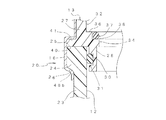
図2に示すように、首部23の上端面25は平坦にされ、フランジ24の外周面は円筒状である。フランジ24の下面は係止段部26であり、その係止段部は内側に向かって下がる傾斜面(テーパ面)にされている。ただし水平にしてもよく(図6参照)、内側に入るにしたがって上がっていく逆傾斜面にすることもできる。容器本体11はこの実施形態では、たとえばポリエチレンテレフタレート(PET)、ポリブチレンテレフタレート(
PBT)、ナイロン(NY)、ポリプロピレン(PP)などの強度および剛性が高い合成
樹脂で、2軸延伸ブロー成形などによって製造される。
As shown in FIG. 2, the
A synthetic resin having high strength and rigidity such as PBT), nylon (NY), and polypropylene (PP), and is manufactured by biaxial stretch blow molding or the like.
前記バルブホルダー13は、概略的には厚肉の円板状の天板27と、その天板の周囲から下方に延びる円筒状の周壁(嵌合部)28とからなる(図4a、図4b参照)。その周壁28の外周面には、Oリング30を装着するためのOリング溝31が形成されている。Oリング30は本発明におけるシール部材であり、Oリング溝(シール溝)31、口部12、フランジ24、係止段部26およびカバー部材16などと共にシール構造20を構成している。バルブホルダー13は合成樹脂によって形成するのが好ましい。それにより複雑な形状でも安価に製造することができる。ただし金属など、他の材料から構成することもできる。
The valve holder 13 is generally composed of a thick disk-shaped
図4aおよび図4bに示すように、バルブホルダー13の天板27の上面には、バルブ14、15を装着するための円筒状の凹所32が左右一対で形成されている。そしてそれぞれの凹所の底板33には、バルブ14、15の下部を容器の内部まで通すための開口34が凹所と同心状に形成されている。底板33における開口34の周縁は、バルブ14、15の段部35と係合する係合段部36である。バルブ14、15の段部35にシール材を設け、係合段部36と当接してシール機能を持たせることもできる。開口34の内周面
と周壁28の内周面との間に段差を設けている。面一とすることもできるが、図4aに示すように、一個所だけ面一になるだけで他の部位では面一にならない。
As shown in FIGS. 4 a and 4 b, a pair of left and right
この実施形態では、底板33の上面における開口34を囲む部位に、バルブ用のOリングなどのシール材(図2の符号37参照)を装着する段部38が形成されている。このOリング37はバルブ14、15とバルブホルダー13の間をシールするものであり、上下に挟圧してもよく、半径方向に挟圧してもよく、さらに両方で挟圧してもよい。他方、天板27の下面で周壁28の外側の部位は、容器本体11の首部の上端面25に当接する当接部40である。そしてこの実施形態では、当接部40は半径方向外向きに延長され、天板27の外周からいくらか突出するフランジないし段部41が形成されている。段部41の外径は容器本体11のフランジ24の外径と同一にしている。この段部41は、カバー部材16を容器本体の口部近辺にかしめ付けるときの係合部として作用する
In this embodiment, a
図1に戻って、前記バルブ14、15は、略円筒状のハウジング42と、そのハウジング内に上下移動自在に収容されるステム43と、そのステムを常時上向きに付勢するスプリングと、ハウジングの上端に設けられる前記ステム孔を開閉するステムラバーとを備えた従来公知のものである。さらにこの実施形態では、ステムラバーおよびステム43をスプリングの付勢力に抗してハウジングに保持させる保持カバー44を備えている。
Returning to FIG. 1, the
保持カバー44はブリキやアルミニウム、ステンレスなどの可塑性の金属薄板を有底筒状にプレス形成したもので、天面中央にステム43を通す開口が形成されている。この実施形態では、小型のエアゾール容器で容器本体の周囲に加締め付けるカバー部材として使用するものをそのまま転用している。2個のバルブ14、15は内部構造や外形が異なってもよい。また、保持カバー44は省略することもできる。その場合はカバー部材16によってガスケットやステム43をハウジング42に保持させる。
The holding cover 44 is formed by pressing a plastic thin metal plate such as tinplate, aluminum, or stainless steel into a bottomed cylindrical shape, and has an opening through which the stem 43 passes in the center of the top surface. In this embodiment, a small aerosol container used as a cover member that is crimped around the container body is used as it is. The two
前記カバー部材16は、図5a、図5bに示すように、上板45とその周囲の側壁46とからなる有底筒状に形成されている。上板45にはステム43を通す2個の開口47が形成されている。2個のバルブ14、15の形状が異なる場合は、それらの開口47の径や形状が異なってもよい。カバー部材16は金属薄板からプレス成形によって製造することができる。ただし合成樹脂によって成形することもできる。側壁46の途中には、バルブホルダー13の外周の段部41と係合する係合段部46aが形成されている。そして側壁46の下端近辺46bは、組付ける前は図5bのように円筒状で真っ直ぐ下に延びており、組付け時に図2に示すように、容器本体11の口部外周の係止段部26に加締め付けられる。加締め加工はたとえばクリンプ爪で内側に曲げたり、ロールフォーミングで密に曲げたりすることにより行う。
As shown in FIGS. 5 a and 5 b, the
前記パウチ17、18は、図1および図3に示すように、2枚のシートの周縁を接合して袋状にしたパウチ本体48と、その上端に取り付けられる筒状の連結部材49とを備えている。パウチ本体48を構成するシートは、ガスバリア性が高い基材、とくにアルミニウム箔などの金属箔と、その金属箔を保護すると共に熱接着性を付与する熱可塑性樹脂フィルムとからなるラミネートシートが好ましい。なおパウチは内容物の色や残量などの状態を目視で確認できるように、透光性の熱可塑性樹脂フィルムからなるシートを用いてもよい。パウチ17、18は可撓性を有し、その中に充填した原液は、容器本体11とパウチ17、18の間の空間に充填されている噴射ガスの圧力で外部に吐出される。熱可塑性樹脂フィルムは金属箔の両面に密に接合されており、周縁50では2枚のシートの内面同士が熱接着されている。金属箔を含むラミネートシートから形成したパウチは、原液の揮発成分がガス化した状態でも透過させない。原液の種類によっては、金属箔を備えない合成樹脂製の内袋、とくにブロー成形などで形成した内袋を採用することもできる。
As shown in FIGS. 1 and 3, each of the
連結部材49は、バルブのハウジング42の下部に突出する筒状突起51と嵌合する筒状部52と、その下端に設けられる舟形ないし菱形形状の接合部53とを有する。接合部53は、パウチ本体48のシート同士が接着される周縁50から連結部材49との接合部に滑らかに移行するように設けたものである。それにより連結部材49とパウチ本体48との接合強度が高くなる。なお接合部は円筒状でもよく楕円筒状でもよい。
The connecting
上記のように構成されるエアゾール容器10は、2個のパウチ17、18に互いに異なる薬剤、たとえば染毛第1剤と染毛第2剤を充填し、容器本体11内にパウチ17、18を加圧するための窒素ガス、炭酸ガス、圧縮空気などの圧縮ガスや、液化石油ガス、ジメチルエーテル、ハイドロフルオロオレフィンなどの液化ガスなどの噴射剤を充填することにより、2液吐出型のエアゾール製品となる。このものは図1に想像線で示すように、2本のステム43に共通のスパウト54付きの押しボタン55を取り付けて用いる。押しボタン55を押下げると、両方のバルブ14、15のステム孔が開き、スパウト54の口部から2液が同時に吐出される。スパウト54内に両方の流路を仕切る仕切り板を設ける場合は、2個の互いに独立したバルブ14、15を用いていることもあって、外部に出るまで内容物を分離させておくことができる。ただし仕切り板を設けないことにより、スパウト内で混合させることも可能である。
In the
各パウチ17、18へ原液を充填するときは、通常はバルブ14、15を取り付ける前に連結部材49から充填し、その後、バルブ14、15を連結部材49に取り付ける。しかしバルブ14、15に取り付けた後、バルブを介して原液を充填することもできる。噴射剤の充填は、カバー部材16を首部23上端に取り付け、加締め付ける前にカバー部材16およびバルブホルダー12を少し持ち上げて容器本体11の首部の上端面との隙間から充填し、その後に加締め付けてシールする、いわゆるアンダーカップ充填の方法を採用することもできる。さらにカバー部材16を加締め付けた後、アンダーカップ充填の場合と同様に、カバー部材16の上面と容器本体11の肩部22にそれぞれ環状のシール部材(図7の符号72、73参照)を当接し、それらの間に加圧した噴射剤を供給することにより、容器本体11とバルブホルダー13の隙間を通して充填することもできる。その場合は容器本体11とバルブホルダー13の間のOリング31が弾性変形して、あるいはシール機能が低下する位置に移動して、シール圧を低下させる。
When filling the
一旦充填した後は、容器本体内の圧力によりOリング30の形状や位置が元に戻り、首部23内面と周壁28外面の間で半径方向に挟圧されるOリング30によって、長期間にわたって安定したシール機能が得られる。さらに外部の温度が上昇するなどにより内圧が上昇してバルブホルダー13やカバー部材16が変形したり、いくらか押上げられても、シール機能にほとんど影響しない。また、カバー部材16の装着位置や装着力にばらつきがあっても、設計したシール圧が得られる。
Once filled, the shape and position of the O-
さらにバルブホルダー13は当接部40を備えているので、バルブホルダー13を安定して首部上端に固定することができる。また、容器本体11として合成樹脂製のボトルを用いているので、首部23の肉厚を他の部位より厚くして剛性を高めることが比較的容易である。そのため、シール構造20の機能を向上することができ、カバー部材16を高い強度でしっかり取り付けることができる。なお、バルブホルダー13にガス充填用の逆止弁を別個に設け、そのガス充填用の逆止弁からガスを充填することもできる。
Furthermore, since the valve holder 13 includes the
図6のエアゾール容器60は、内部に仕切り61を設けた1個のパウチ62を採用している点に特徴があり、他は図1のエアゾール容器10と実質的に同一である。すなわち図1のエアゾール容器10ではそれぞれのバルブ14、15にパウチ17、18を吊り下げているが、図6に示すエアゾール容器60のパウチ62は3枚のシートを重ねて周縁(図3の符号50参照)を接着し、それにより内部を仕切り61で2つの画室63、64に区
画している。そしてそれぞれの画室63、64とバルブ14、15とを1個の連結部材65で連結している。
The aerosol container 60 of FIG. 6 is characterized in that one pouch 62 having a partition 61 provided therein is employed, and the other is substantially the same as the
連結部材65にはそれぞれのバルブ14、15の筒状突起51と密に嵌合する嵌合穴66と、連通孔67が形成されている。さらに連結部材65の下面に段差を設け、それらの段差の間に形成される縦方向の面68に仕切り61の上端近辺を接着している。それにより仕切り61と連結部材65とを、より確実にシールすることができる。
The connecting member 65 is formed with a fitting hole 66 and a
図7に示すシール構造70では、バルブホルダー13の当接部40にガスを通す溝71が形成されている。その溝71は内外を連通していればよく、通常は1〜4本程度、半径方向ないし放射状に設ける。この溝71により、バルブホルダー13と容器本体11とをしっかり固着していても、ガス通路が確保され、カバー部材16を加締めた後でもガス充填をスムーズに行うことができる。図7の符号72,73は、ガス充填のときの充填装置のシールポイントを示している。ガスを通す溝71は、エアゾール製品が異常な高温に晒されたとき、ガスを逃がして破裂や蓋飛びを防止する機能をも奏しうる。ガスを通す溝は、容器本体11の首部の上端面25に形成してもよく、首部の上端面とバルブホルダー13の当接部40の両方に設けてもよい。また、フランジ部の外周面に縦方向に延びる溝を設けても良い。
In the
さらに図7のシール構造70では、バルブホルダー13の周壁28のOリング溝74として、上下に長く、下方にいくほど溝底面の外径が小さくなるように傾斜させたテーパ状のものを採用している。それにより、Oリング30が上方(シール部)のときはシールが確実で、ガス充填のときは、想像線のように下方(シール解除部)にずれるため、Oリング30の外周面と開口部12の内面との間のシール圧が減少し、隙間が生じやすくなる。それによりガス充填がスムーズになる。充填後は内圧でOリング30が上方に移動し、シール圧が高くなる。この上下に長いOリング溝74は、前述のガスを通す溝71と一緒に採用するのが好ましい。ただしガスを通す溝71および上下に長いテーパ状のOリング溝74はそれぞれ単独で採用することもできる。
Further, in the
前記Oリング溝74は、溝の底面が下方に行くに従って小径となるテーパ状であるが、上方(シール部)で径が大きく下方(シール解除部)で小径となるように2段に形成してもよい。ただしOリング30の移動がスムーズになるように、段部の境界は滑らかにする。バルブホルダー13の周壁28にOリング溝31、74を形成せず、単なるテーパ面とすることもできる。ただしOリング30が脱落しにくいように、周壁28の下方外周面に環状突起ないし段部を設けるのが好ましい。バルブホルダー13にOリング溝31、74を形成することに代えて、あるいは設けるのと共に、開口12の内面にOリング溝を形成することもできる。この場合もOリング30は半径方向に圧縮されて弾性変形し、シール作用を発揮する。また、開口12の内面にOリング溝を設ける場合は、上方(シール部)で小径とし、下方(シール解除部)で大径となるようにテーパ状ないし段状にするのが好ましい。
The O-
図7のシール構造70では、さらに容器本体11の首部23とフランジ24の境界部にガスを通す溝75を形成している。その溝75は首部23の周囲に複数個、縦向きに設ける。ただし環状の溝であってもよい。首部23の上端のフランジ24の外周面にガスを通す縦溝を形成してもよい。図7の実施形態では、カバー部材16の下端近辺46bはフランジ24の下面の係止段部26に沿わせず、ほぼ直角に曲げて加締め付けている。それにより係止段部26とカバー部材の下端近辺との間に隙間ができるが、これによりガス充填が容易になり、また、容器本体が熱と内圧により変形したときのガスの排出を確実に行える。
In the
図8a、図8bのシール構造76は、首部23の上端内面にOリング30を逃がすための切り欠き段部77がシール解除部として設けられている。さらにこの実施形態では、バルブホルダー13の周壁28にガスを逃がすための縦溝78が形成されている。このシール構造76は、通常の状態では図8aのように、首部23がほぼ真っ直ぐな円筒状であり、Oリング30はOリング溝31内に入っている。そして環境温度が異常な高温になり、合成樹脂製の容器本体11が図8bの矢印Pのように変形して下方に向かって拡がると、上昇した内圧により、Oリング30がもとのOリング溝31から押し出されて切り欠き段部77の中に移動する。そのとき、Oリング30の内周面と周壁28の表面の間は、縦溝78によって上下が連通している。そのため、容器本体11の内部のガスは、縦溝78を通り、さらに半径方向の溝71を通って外部に放出され、バルブホルダー13やカバー部材16などの蓋体が抜け飛ぶのが防止される。
8A and 8B is provided with a
図9に示すシール構造79は、Oリング溝31が容器本体11の肉厚が薄くなる位置、すなわちフランジ24の下部に対応する位置に設けられている。他の点は図2あるいは図7のシール構造と同様である。このものも異常な高温で合成樹脂製の容器本体11が想像線で示すように変形すると、Oリング30にかかる半径方向の加圧力が弱くなり、シールが解除され、ガスが抜け出る。それによりバルブホルダー13などが抜け飛ぶのが防止される。
The seal structure 79 shown in FIG. 9 is provided at a position where the O-ring groove 31 corresponds to the position where the thickness of the container body 11 becomes thin, that is, the lower portion of the
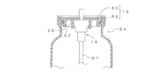
図10に示すエアゾール容器80は、バルブ14が1個であること、およびパウチなどの内袋を備えていないことを除けば、図1のエアゾール容器10と実質的に同一である。このエアゾール容器80は、パウチを備えていないので、内部には噴射剤と原液とを混合状態で充填する。また、パウチを備えないので、バルブ14の下端にディップチューブ81を連結している。上下を逆にして吐出するエアゾール容器では、ディップチューブは使用しない。
The aerosol container 80 shown in FIG. 10 is substantially the same as the
このエアゾール容器80のバルブホルダー13は、周壁28のほかに、バルブ14を保持するための円筒状のバルブ保持部82を設け、それらの間に放射状にリブ83を設けている。カバー部材16は図1の場合と同様のものを使用することができる。なお、バルブ14は、ガスケットやステムをハウジングに取り付けるための保持カバー(図1の符号44参照)を省略し、バルブホルダー13で固定させることもできる。
In addition to the
図11に示すエアゾール容器84は、カバー部材16が円板状の天板85とリング状の周辺部86とに分かれているほかは、図7のエアゾール容器80と実質的に同一である。周辺部86は、円筒状の部材でフランジ24やバルブホルダー13の周囲を囲んだ後、下端および上端をそれぞれ加締め付けることにより、固定する。図10および図11のエアゾール容器80、84において、バルブ14に1個のパウチなどの内袋を設けて二重エアゾール容器とすることもできる(図1のパウチ17参照)。また、このようなバルブが1個のエアゾール容器80、84においても、図2のシール構造20のほか、図7、図8、図9などの種々のシール構造70,76、79を採用することができる。
The aerosol container 84 shown in FIG. 11 is substantially the same as the aerosol container 80 of FIG. 7 except that the
図12に示すエアゾール容器88は、容器本体89として金属缶を採用しておいる。そしてバルブ14にパウチ17を吊り下げている。他の点は図10のエアゾール容器80と実質的に同一である。容器本体89は胴部90、肩部91および首部92を一体成形したモノブロック缶であり、首部の上端に環状のビード部93を設けている。底部、胴部、眼鏡部(ドーム)を備えたスリーピース缶であってもよい。眼鏡部にはビード部を設ける。このエアゾール容器88では、バルブ14に連結部材を介してパウチ17を取り付けており、それにより二重エアゾール容器としている。ビード部93は首部の上端を外向きにカール成形したものである。
The
さらにこの実施形態では、ビード部93を断面矩形状に塑性変形している。この実施形態ではビード部93は上面が平坦で、外周面が円筒状であり、下面もほぼ平坦である。それにより、カバー部材16の下端とビード部93の下面との係合が確実になり、バルブホルダー13の固着強度が高くなる。下面は図1と同様に外にいくほど上にいくテーパ状としてもよく、逆テーパ状とすることもできる。バルブホルダー13と容器本体89との間のシール構造20は、図1の場合と実質的に同一である。
Further, in this embodiment, the
図13に示すエアゾール容器94は、容器本体89として図11と同様の金属缶を採用しているほかは、図1のエアゾール容器10と実質的に同一である。容器本体89の上端のビード部93は断面略矩形状としている。また、2個のバルブ14、15およびバルブホルダー13、カバー部材16、連結部材49は図1の場合と同様である。図12、図13のエアゾール容器88、94についても、前述のいずれのシール構造も採用することができ、それぞれのシール構造の効果を奏することができる。
The
前記実施形態ではいずれも容器本体の上端の開口をバルブホルダーとバルブで塞いでいるが、本発明のシール構造はバルブを有しない単なる蓋体を閉じる場合にも採用することができる。また、カバー部材を容器本体に取り付ける構造としては、前述の加締めのほか、特許文献2のねじ締め式のキャップと同様にねじ締めを採用することも可能である。本発明のシール構造に用いるシール部材は、通常は断面円形で、全体が円形リング状のOリングであるが、断面角形や、全体の形状が楕円状など、他の形状のシール部材を採用することもできる。
In any of the above-described embodiments, the opening at the upper end of the container body is closed with a valve holder and a valve. However, the seal structure of the present invention can also be used when a simple lid having no valve is closed. Further, as a structure for attaching the cover member to the container main body, in addition to the above-described caulking, it is possible to employ screw tightening in the same manner as the screw tightening type cap disclosed in
10 二重エアゾール容器
11 容器本体
12 上端開口部(口部)
13 バルブホルダー
14、15 バルブ
16 カバー部材
17、18 パウチ
20 シール構造
21 胴部
22 肩部
23 首部
24 フランジ
25 上端面
26 係止段部
27 天板
28 周壁
30 Oリング
31 Oリング溝
32 凹所
33 底板
34 開口
35 段部
36 係合段部
37 バルブ用のOリング(シール材)
38 段部
40 当接部
41 段部
42 ハウジング
43 ステム
44 保持カバー
45 上板
46 側壁
46a 係合段部
46b 下端近辺
47 開口
48 パウチ本体
49 連結部材
50 周縁
51 筒状突起
52 筒状部
53 接合部
54 スパウト
55 押しボタン
60 エアゾール容器
61 仕切り
62 パウチ
63、64 画室
65 連結部材
66 嵌合穴
67 連通孔
68 縦方向の面
70 シール構造
71 溝
72、73 シールポイント
74 上下に長いOリング溝
75 (ガスを通す)溝
76 シール構造
77 切り欠き段部
78 縦溝
79 シール構造
80 エアゾール容器
81 ディップチューブ
82 バルブ保持部
83 リブ
84 エアゾール容器
85 天板
86 周辺部
88 エアゾール容器
89 容器本体
90 胴部
91 肩部
92 首部
93 ビード部
94 エアゾール容器
10 Double aerosol container 11 Container body 12 Upper end opening (mouth)
13
38
53 Joint part 54 Spout 55 Push button 60 Aerosol container 61 Partition 62
Claims (10)
前記口部の内周面が平滑な円筒状であり、
前記蓋体が口部の内部に嵌入される周壁を備え、
前記蓋体の周壁の外周面に前記シール部材を保持する環状のシール溝が形成されており、
前記シール部材が前記蓋体の周壁のシール溝の底面と前記容器本体の口部の内周面との間に介在され、半径方向に加圧されることにより弾性変形するリング状の部材であり、
さらに前記蓋体を前記容器本体の上端に固着するためのカバー部材を備えており、
前記容器本体の外周に係止段部が設けられており、前記カバー部材の下端周縁がその係止段部にかしめられており、
前記蓋体がエアゾールバルブを保持するバルブホルダーであり、前記容器本体が耐圧容器である容器口部のシール構造。 A container mouth seal structure comprising a mouth opening at the upper end of the container body, a lid for closing the mouth, and a seal member interposed therebetween,
The inner peripheral surface of the mouth is a smooth cylindrical shape,
The cover includes a peripheral wall that is inserted into the mouth,
An annular seal groove for holding the seal member is formed on the outer peripheral surface of the peripheral wall of the lid,
The seal member is a ring-shaped member that is interposed between the bottom surface of the seal groove on the peripheral wall of the lid and the inner peripheral surface of the mouth of the container body, and is elastically deformed by being pressurized in the radial direction. ,
Furthermore, a cover member for fixing the lid to the upper end of the container body is provided ,
A locking step is provided on the outer periphery of the container body, and the lower end periphery of the cover member is caulked to the locking step.
A container mouth seal structure in which the lid is a valve holder for holding an aerosol valve, and the container body is a pressure resistant container .
前記首部の内部が口部となっており、
前記フランジの下面が係止段部となっており、
前記蓋体の周壁のシール溝がフランジの下面に対応する位置に設けられている請求項8記載の容器口部のシール構造。The container body has a cylindrical neck portion formed with a flange projecting outward on the outer periphery of the upper end;
The inside of the neck is a mouth,
The lower surface of the flange is a locking step,
The seal structure of the container mouth part of Claim 8 with which the seal groove of the surrounding wall of the said cover body is provided in the position corresponding to the lower surface of a flange.
Priority Applications (9)
| Application Number | Priority Date | Filing Date | Title |
|---|---|---|---|
| JP2010286748A JP5965580B2 (en) | 2010-12-22 | 2010-12-22 | Container mouth seal structure |
| CN201180061656.9A CN103328347B (en) | 2010-12-22 | 2011-12-22 | Valve assembly and aerosol container equipped with same, and aerosol product and process for production thereof |
| PCT/JP2011/079944 WO2012086818A1 (en) | 2010-12-22 | 2011-12-22 | Valve assembly and aerosol container equipped with same, and aerosol product and process for production thereof |
| EP11850794.6A EP2657151B1 (en) | 2010-12-22 | 2011-12-22 | Valve assembly and aerosol container equipped with same, and aerosol product and process for production thereof |
| CN201811468858.5A CN109606931B (en) | 2010-12-22 | 2011-12-22 | Valve retainer |
| CN201510205795.4A CN105197430B (en) | 2010-12-22 | 2011-12-22 | The sealing structure and valve retainer of aerosol container |
| US13/996,752 US9475636B2 (en) | 2010-12-22 | 2011-12-22 | Valve assembly and aerosol container equipped with the same, and aerosol product and process for production thereof |
| AU2011345795A AU2011345795C1 (en) | 2010-12-22 | 2011-12-22 | Valve assembly and aerosol container equipped with same, and aerosol product and process for production thereof |
| US15/196,845 US9926130B2 (en) | 2010-12-22 | 2016-06-29 | Valve assembly and aerosol container equipped with the same, and aerosol product and process for production thereof |
Applications Claiming Priority (1)
| Application Number | Priority Date | Filing Date | Title |
|---|---|---|---|
| JP2010286748A JP5965580B2 (en) | 2010-12-22 | 2010-12-22 | Container mouth seal structure |
Publications (3)
| Publication Number | Publication Date |
|---|---|
| JP2012131553A JP2012131553A (en) | 2012-07-12 |
| JP2012131553A5 JP2012131553A5 (en) | 2014-01-16 |
| JP5965580B2 true JP5965580B2 (en) | 2016-08-10 |
Family
ID=46647635
Family Applications (1)
| Application Number | Title | Priority Date | Filing Date |
|---|---|---|---|
| JP2010286748A Active JP5965580B2 (en) | 2010-12-22 | 2010-12-22 | Container mouth seal structure |
Country Status (1)
| Country | Link |
|---|---|
| JP (1) | JP5965580B2 (en) |
Families Citing this family (6)
| Publication number | Priority date | Publication date | Assignee | Title |
|---|---|---|---|---|
| JP2014040270A (en) * | 2012-08-23 | 2014-03-06 | Daizo:Kk | Double aerosol container |
| WO2014077273A1 (en) | 2012-11-16 | 2014-05-22 | 株式会社ダイゾー | Discharge container and method for manufacturing discharge container |
| JP6389624B2 (en) * | 2014-03-11 | 2018-09-12 | 株式会社ダイゾー | O-ring seal structure and pressurized container using the same |
| WO2017134823A1 (en) * | 2016-02-05 | 2017-08-10 | ジャパンポーレックス株式会社 | Lid |
| EP3688332A2 (en) * | 2017-09-29 | 2020-08-05 | L'oreal | Drive shaft coupling |
| CN110789764A (en) * | 2019-10-23 | 2020-02-14 | 泛卡医药科技(上海)有限公司 | Rapid packaging method of aerosol packaging system |
Family Cites Families (9)
| Publication number | Priority date | Publication date | Assignee | Title |
|---|---|---|---|---|
| JPS4310851Y1 (en) * | 1965-03-18 | 1968-05-11 | ||
| JPS5655680Y2 (en) * | 1976-09-16 | 1981-12-25 | ||
| CH680359A5 (en) * | 1991-08-28 | 1992-08-14 | Supermatic Kunststoff Ag | |
| JPH09195870A (en) * | 1996-01-23 | 1997-07-29 | Aisin Takaoka Ltd | Intake manifold and its assembling method |
| JP3951038B2 (en) * | 1997-12-15 | 2007-08-01 | 株式会社ダイゾー | Lid fixing structure and pressure dispenser product |
| JP3749051B2 (en) * | 1999-10-29 | 2006-02-22 | 株式会社吉野工業所 | Aerosol container that prevents explosion |
| JP4931293B2 (en) * | 2001-07-05 | 2012-05-16 | 株式会社ダイゾー | Pressure vessel seal structure |
| JP4805598B2 (en) * | 2005-04-15 | 2011-11-02 | 日東工器株式会社 | Male / female member assembly |
| JP5283939B2 (en) * | 2008-03-19 | 2013-09-04 | 株式会社三谷バルブ | Aerosol container and aerosol product using the aerosol container |
-
2010
- 2010-12-22 JP JP2010286748A patent/JP5965580B2/en active Active
Also Published As
| Publication number | Publication date |
|---|---|
| JP2012131553A (en) | 2012-07-12 |
Similar Documents
| Publication | Publication Date | Title |
|---|---|---|
| JP5965580B2 (en) | Container mouth seal structure | |
| US20200140153A1 (en) | Container | |
| JP6140610B2 (en) | Two liquid discharge product | |
| CA2905117C (en) | Container | |
| CN110325474B (en) | Pail closure with integrated venting system | |
| JP6236247B2 (en) | Discharge container | |
| JP6480121B2 (en) | Discharge container and discharge product manufacturing method | |
| WO2014077273A1 (en) | Discharge container and method for manufacturing discharge container | |
| US5865351A (en) | Pressurized device for the dispensing of liquid of creamy products | |
| JP6147206B2 (en) | Double container | |
| JP4236693B2 (en) | Double aerosol container | |
| CN102741605A (en) | A gas cylinder, and a method for providing such cylinder | |
| JP4114725B2 (en) | Manufacturing method of double aerosol device and double aerosol container | |
| US4211344A (en) | Sack retention and pressurizing for aerosol type dispensers | |
| JP2013230852A (en) | Double aerosol product | |
| JP2004131187A (en) | Propellant filling method for double aerosol device | |
| JP5001680B2 (en) | Pressurized container for tube container and pressurized tube product using the same | |
| JP6691728B2 (en) | Discharge product manufacturing method | |
| JP6148456B2 (en) | Discharge container and method for manufacturing discharge container | |
| JP6108672B2 (en) | Valve assembly and discharge container using the same | |
| JP2021001023A (en) | Double structure container | |
| KR200446846Y1 (en) | High viscosity liquid vessel | |
| JP3441202B2 (en) | Double aerosol container | |
| JP7195043B2 (en) | Double container with outer case | |
| JP3984033B2 (en) | Pressure vessel seal structure |
Legal Events
| Date | Code | Title | Description |
|---|---|---|---|
| A521 | Request for written amendment filed |
Free format text: JAPANESE INTERMEDIATE CODE: A523 Effective date: 20131120 |
|
| A621 | Written request for application examination |
Free format text: JAPANESE INTERMEDIATE CODE: A621 Effective date: 20131120 |
|
| A131 | Notification of reasons for refusal |
Free format text: JAPANESE INTERMEDIATE CODE: A131 Effective date: 20141118 |
|
| A521 | Request for written amendment filed |
Free format text: JAPANESE INTERMEDIATE CODE: A523 Effective date: 20150114 |
|
| A521 | Request for written amendment filed |
Free format text: JAPANESE INTERMEDIATE CODE: A523 Effective date: 20150216 |
|
| A131 | Notification of reasons for refusal |
Free format text: JAPANESE INTERMEDIATE CODE: A131 Effective date: 20150901 |
|
| A521 | Request for written amendment filed |
Free format text: JAPANESE INTERMEDIATE CODE: A523 Effective date: 20151102 |
|
| TRDD | Decision of grant or rejection written | ||
| A01 | Written decision to grant a patent or to grant a registration (utility model) |
Free format text: JAPANESE INTERMEDIATE CODE: A01 Effective date: 20160621 |
|
| A61 | First payment of annual fees (during grant procedure) |
Free format text: JAPANESE INTERMEDIATE CODE: A61 Effective date: 20160704 |
|
| R150 | Certificate of patent or registration of utility model |
Ref document number: 5965580 Country of ref document: JP Free format text: JAPANESE INTERMEDIATE CODE: R150 |
|
| R250 | Receipt of annual fees |
Free format text: JAPANESE INTERMEDIATE CODE: R250 |
|
| R250 | Receipt of annual fees |
Free format text: JAPANESE INTERMEDIATE CODE: R250 |