JP4333709B2 - 筒内噴射式内燃機関の制御装置 - Google Patents
筒内噴射式内燃機関の制御装置 Download PDFInfo
- Publication number
- JP4333709B2 JP4333709B2 JP2006217652A JP2006217652A JP4333709B2 JP 4333709 B2 JP4333709 B2 JP 4333709B2 JP 2006217652 A JP2006217652 A JP 2006217652A JP 2006217652 A JP2006217652 A JP 2006217652A JP 4333709 B2 JP4333709 B2 JP 4333709B2
- Authority
- JP
- Japan
- Prior art keywords
- fuel
- pressure
- fuel injection
- control device
- injection
- Prior art date
- Legal status (The legal status is an assumption and is not a legal conclusion. Google has not performed a legal analysis and makes no representation as to the accuracy of the status listed.)
- Expired - Fee Related
Links
Images


Classifications
-
- F—MECHANICAL ENGINEERING; LIGHTING; HEATING; WEAPONS; BLASTING
- F02—COMBUSTION ENGINES; HOT-GAS OR COMBUSTION-PRODUCT ENGINE PLANTS
- F02D—CONTROLLING COMBUSTION ENGINES
- F02D41/00—Electrical control of supply of combustible mixture or its constituents
- F02D41/30—Controlling fuel injection
- F02D41/38—Controlling fuel injection of the high pressure type
- F02D41/3809—Common rail control systems
- F02D41/3836—Controlling the fuel pressure
-
- F—MECHANICAL ENGINEERING; LIGHTING; HEATING; WEAPONS; BLASTING
- F02—COMBUSTION ENGINES; HOT-GAS OR COMBUSTION-PRODUCT ENGINE PLANTS
- F02D—CONTROLLING COMBUSTION ENGINES
- F02D35/00—Controlling engines, dependent on conditions exterior or interior to engines, not otherwise provided for
- F02D35/02—Controlling engines, dependent on conditions exterior or interior to engines, not otherwise provided for on interior conditions
- F02D35/023—Controlling engines, dependent on conditions exterior or interior to engines, not otherwise provided for on interior conditions by determining the cylinder pressure
-
- F—MECHANICAL ENGINEERING; LIGHTING; HEATING; WEAPONS; BLASTING
- F02—COMBUSTION ENGINES; HOT-GAS OR COMBUSTION-PRODUCT ENGINE PLANTS
- F02D—CONTROLLING COMBUSTION ENGINES
- F02D41/00—Electrical control of supply of combustible mixture or its constituents
- F02D41/30—Controlling fuel injection
- F02D41/38—Controlling fuel injection of the high pressure type
- F02D41/3809—Common rail control systems
- F02D41/3836—Controlling the fuel pressure
- F02D41/3845—Controlling the fuel pressure by controlling the flow into the common rail, e.g. the amount of fuel pumped
Landscapes
- Engineering & Computer Science (AREA)
- Chemical & Material Sciences (AREA)
- Combustion & Propulsion (AREA)
- Mechanical Engineering (AREA)
- General Engineering & Computer Science (AREA)
- Electrical Control Of Air Or Fuel Supplied To Internal-Combustion Engine (AREA)
- Combined Controls Of Internal Combustion Engines (AREA)
- Fuel-Injection Apparatus (AREA)
Description
(特許文献1及び2参照)
505では、該AD変換された燃圧センサの入力値を一定の定期Job(例えば、2ms)毎に入力処理を行い、ブロック506にて物理値(センサ入力電圧mV→物理値MPa)に換算する。ブロック507では、燃料配管内の燃圧脈動(脈動が生じるのは、図4で説明した通りである)に対し、平均値を求めるために、フィルタリング処理(移動平均処理や加重平均処理)を行い、該フィルタリング処理された燃圧認識値に基づいて、目標燃圧になるように、ブロック508にて目標燃圧フィードバック制御を行う。該燃圧フィードバック制御と予め設定されたオープン制御により求められた高圧燃料ポンプの駆動タイミング(高圧燃料ポンプへ出力するパルスのタイミング)を算出して、ブロック501の駆動回路を介して、高圧燃料ポンプ内のソレノイドを駆動制御する。
509で算出された噴射パルス幅と、該噴射タイミングから、ブロック511にて噴射開始のタイミングと噴射終了のタイミングを算出する。ブロック512では、高圧燃料ポンプからの燃料噴射量と、前記ブロック511で算出された噴射開始と噴射終了のタイミングにより、予め設定されたポンプ吐出量マップから、ブロック513にて燃料噴射中の高圧ポンプからの燃料吐出量を算出する。また、燃料噴射量は、前記ブロック509で算出されており、該燃料噴射量と、ブロック513で算出した値により、ブロック516にて燃料噴射中の燃料配管内の燃料収支を演算する。一方、ブロック514では燃料噴射弁から燃料を噴射開始するタイミングで燃圧センサのサンプリングを行い、燃料噴射開始時の燃圧値として入力し、ブロック515にて、物理値(センサ入力電圧mV→物理値MPa)に換算する。ブロック517では、前記ブロック515で求めた燃料噴射開始時の燃圧と、前記ブロック516で算出した燃料収支から、燃料噴射弁に対する燃圧補正を行い、ブロック503の燃料噴射弁駆動回路を介して、燃料噴射弁(図中のインジェクタ)を駆動制御する。
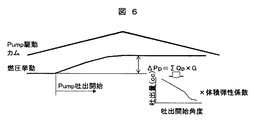
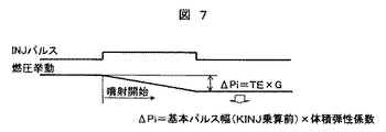
(例えば、2ms毎)にサンプリングを行う。ブロック1202では、前記ブロック1201によりサンプリングされた燃圧値に基づいて、高圧燃料ポンプのソレノイドを駆動するパルスタイミングを演算する。ブロック1203では、内燃機関の運転状態から要求燃料噴射パルス幅を算出する。ブロック1204では、前記ブロック1203で算出された噴射パルス幅に基づいて燃料噴射量を算出する。ここで、燃料噴射パルス幅から燃料噴射量への算出は、燃料噴射弁の流量特性に基づいて算出すれば良い。その関係は、前記図3の燃料噴射弁の流量特性から1次式の演算で算出可能である。例えば、燃料噴射弁の有効パルス幅(燃料噴射パルスに対し、実際に燃料噴射弁が開弁しているパルス幅)から燃圧特性を無次元化(本来の燃料噴射弁の燃圧補正を与えない)した演算を行い、これに燃料噴射弁特性の傾き特性値を予め求めておき、乗算すれば良く、前記図7で説明した通りである。
1209では、前記ブロック1207でサンプリングした燃料噴射弁から燃料噴射開始するタイミングでの燃圧値と前記ブロック1206で算出した前記燃料収支から、燃料噴射中の燃圧変化を演算する。ここで、燃料変化=燃料噴射開始時の燃圧+燃料噴射中の燃圧変化であり、燃料噴射中の燃圧変化は、燃料噴射中の燃料配管内の燃料収支から容易に算出可能であり、前記図6及び図7で説明した通りである。ブロック1210では、前記ブロック1209で算出した値、即ち前記図4で説明した燃料圧力重心点を算出した値もしくは、前記ブロック1208と1209より算出した燃料圧力値に対し予め定めた割合を乗算した値の燃圧値に基づいて、燃料噴射弁の燃圧補正を行う。ブロック1211では、前記ブロック1210で算出した燃圧補正演算を用いて燃料噴射弁に出力するパルス幅を算出して、ブロック1212にて、実際に燃料噴射弁に燃料噴射パルス幅を出力する。
Mpa)に保たれている。従って、燃料噴射弁からの燃料噴射量が多くても、燃料配管内の燃圧は最低でも前記フィード圧までしか低下しない。その為、前記図12及び図13で説明した燃料噴射中の燃料配管内の燃圧値演算を行う場合には、このようにフィード圧以上の制限をする必要があり、この制限を与えないと実際の燃料配管内の燃圧とは異なる演算をすることになり、その結果、該フィード圧近辺での燃圧での燃料噴射量制御の精度が悪化(燃料噴射量を多く制御)してしまうことになる。
Claims (14)
- 燃料ポンプにより燃料が供給される燃料配管と、
前記燃料配管の燃料圧力を検出する燃料圧力検出手段と、
前記燃料配管内の燃料を内燃機関の各気筒に噴射する燃料噴射弁と、
所定のタイミングで、前記燃料圧力をサンプリングする手段とを備える内燃機関の制御装置において、
前記制御装置は、
前記燃料噴射弁からの燃料噴射量を算定する燃料量算定手段と、
前記高圧燃料ポンプからの燃料配管に燃料を供給する吐出量を算定する手段と、
前記燃料噴射弁が噴射を開始してから終了するまでの前記燃料噴射量と前記吐出量との差分を予め求める手段とを有し、
前記燃料噴射弁が噴射を開始する時点での燃料圧力と前記差分とに基づいて、
前記燃料噴射弁を制御する基準燃圧値を求めると共に前記基準燃圧値に基づいて前記燃料噴射弁を制御することを特徴とする制御装置。 - 請求項1記載の制御装置において、
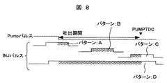
前記燃料噴射弁からの燃料噴射量を算定する手段は、他の気筒の燃料噴射弁と噴射期間が重なっているか否かを判定する判定手段を有し、前記判定手段の結果、他の気筒と噴射が重なっている場合には、前記重なり期間分の燃料噴射量を補正することを特徴とする制御装置。 - 請求項1記載の制御装置において、
前記燃料噴射期間における燃料吐出量を算定する手段は、予め設定された燃料ポンプからの吐出量特性をデータとして記録しておくと共に、前記データは、少なくても内燃機関のクランク角度と内燃機関の回転数の何れか1つ以上のパラメータにより、算定することを特徴とする制御装置。 - 請求項3記載の制御装置において、
前記燃料噴射期間中の吐出量を算定する手段は、燃料噴射開始のタイミングと燃料ポンプからの吐出タイミングの何れか遅い方と、燃料噴射弁からの噴射終了までの期間により吐出量を算定することを特徴とする制御装置。 - 請求項1から4の何れかに記載の制御装置において、
燃料噴射を終了するタイミングは、前記一定周期で検出した燃料圧力に基づいて算定された燃料噴射パルス幅に基づいて、算定することを特徴とする制御装置。 - 請求項1から5の何れかに記載の制御装置において、
燃料噴射弁を制御する基準燃圧値は、前記燃料噴射開始するタイミングでの燃料圧力と前記燃料噴射量と吐出量の差分値より求められる燃料噴射終了タイミングでの燃料圧力差により求められる燃料圧力に対し予め定める割合を乗じて算定した燃料圧力により燃料噴射弁制御の補正を行うことを特徴とする制御装置。 - 請求項1から5の何れかに記載の制御装置において、
燃料噴射弁を制御する基準燃圧値は、
前記燃料噴射開始するタイミングでの燃料圧力と、前記燃料噴射するタイミングでの前記燃料圧力差と前記噴射開始するタイミングでの燃料圧力より仮想的に求まる燃料圧力面積の圧力重心点を算定した燃料圧力により、燃料噴射弁制御の補正を行うことを特徴とする制御装置。 - 請求項1から6の何れかに記載の制御装置において、
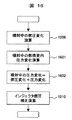
前記燃料圧力検出手段が異常又は故障と判定された場合には、前記燃料圧力検出値を固定値とすることを特徴とする制御装置。 - 請求項1から6の何れかに記載の制御装置において、
前記高圧燃料ポンプが異常又は故障と判定された場合には、前記燃料噴射中の吐出量を一定値として算出するまたは、高圧燃料ポンプからの燃料吐出タイミングを一定値とすると共に、前記一定値は、全吐出(フル吐出)と無吐出故障で各々別々の値とすることを特徴とする制御装置。 - 請求項2記載の制御装置において、前記補正は前記重なり期間分の燃料噴射量を加算し算出することを特徴とする制御装置。
- 請求項1又は2に記載の制御装置において、前記高圧ポンプからの燃料吐出量は、前記燃料噴射開始タイミングと上記燃料噴射される期間から求まる燃料噴射終了タイミングでの高圧ポンプ吐出量を引くことを特徴とする制御装置。
- 請求項11に記載の制御装置において、高圧ポンプの吐出量はクランク角度と内燃機関の回転数より算出することを特徴とする制御装置。
- 請求項1に記載の制御装置において、前記燃料量算出手段により求められる燃料噴射量は、上記噴射期間(パルス幅)から燃圧の補正量を除いた値から算出することを特徴とする制御装置。
- 請求項1に記載の制御装置において、前記燃料算出手段により求められる燃料噴射量は、燃料噴射中の燃圧変化を算出して、該燃圧変化量と噴射開始時の燃圧に基づいて、燃料噴射パルス幅を補正することを特徴とする制御装置。
Priority Applications (4)
| Application Number | Priority Date | Filing Date | Title |
|---|---|---|---|
| JP2006217652A JP4333709B2 (ja) | 2006-08-10 | 2006-08-10 | 筒内噴射式内燃機関の制御装置 |
| EP07015503.1A EP1892403B1 (en) | 2006-08-10 | 2007-08-07 | Control apparatus for direct injection type internal combustion engine |
| US11/834,951 US7418337B2 (en) | 2006-08-10 | 2007-08-07 | Control apparatus for direct injection type internal combustion engine |
| US12/164,555 US7610141B2 (en) | 2006-08-10 | 2008-06-30 | Control apparatus for direct injection type internal combustion engine |
Applications Claiming Priority (1)
| Application Number | Priority Date | Filing Date | Title |
|---|---|---|---|
| JP2006217652A JP4333709B2 (ja) | 2006-08-10 | 2006-08-10 | 筒内噴射式内燃機関の制御装置 |
Related Child Applications (1)
| Application Number | Title | Priority Date | Filing Date |
|---|---|---|---|
| JP2008321715A Division JP2009092075A (ja) | 2008-12-18 | 2008-12-18 | 筒内噴射式内燃機関の制御装置 |
Publications (2)
| Publication Number | Publication Date |
|---|---|
| JP2008038857A JP2008038857A (ja) | 2008-02-21 |
| JP4333709B2 true JP4333709B2 (ja) | 2009-09-16 |
Family
ID=38596015
Family Applications (1)
| Application Number | Title | Priority Date | Filing Date |
|---|---|---|---|
| JP2006217652A Expired - Fee Related JP4333709B2 (ja) | 2006-08-10 | 2006-08-10 | 筒内噴射式内燃機関の制御装置 |
Country Status (3)
| Country | Link |
|---|---|
| US (2) | US7418337B2 (ja) |
| EP (1) | EP1892403B1 (ja) |
| JP (1) | JP4333709B2 (ja) |
Families Citing this family (26)
| Publication number | Priority date | Publication date | Assignee | Title |
|---|---|---|---|---|
| JP2006029088A (ja) * | 2004-07-12 | 2006-02-02 | Yanmar Co Ltd | 蓄圧式燃料噴射装置及びその蓄圧式燃料噴射装置を備えた内燃機関 |
| JP2007332783A (ja) * | 2006-06-12 | 2007-12-27 | Nissan Motor Co Ltd | エンジンの燃料供給方法及びエンジンの燃料供給装置 |
| JP4333709B2 (ja) * | 2006-08-10 | 2009-09-16 | 株式会社日立製作所 | 筒内噴射式内燃機関の制御装置 |
| EP2058498B1 (en) * | 2007-11-09 | 2013-07-10 | Continental Automotive GmbH | Method to determine the fuel temperature in a common rail injection system |
| JP5105422B2 (ja) * | 2008-01-18 | 2012-12-26 | 三菱重工業株式会社 | 蓄圧式燃料噴射装置の蓄圧室圧力制御方法および制御装置 |
| JP2010025102A (ja) * | 2008-06-16 | 2010-02-04 | Hitachi Ltd | 内燃機関の制御診断装置 |
| DE102008035985B4 (de) * | 2008-08-01 | 2010-07-08 | Continental Automotive Gmbh | Verfahren und Vorrichtung zur Regelung des Kraftstoffdruckes im Druckspeicher eines Common-Rail-Einspritzsystems |
| JP5040884B2 (ja) * | 2008-10-09 | 2012-10-03 | 株式会社デンソー | 燃料噴射制御装置 |
| JP5045640B2 (ja) * | 2008-10-27 | 2012-10-10 | 株式会社デンソー | 筒内噴射式内燃機関の燃料噴射制御装置 |
| JP5126102B2 (ja) * | 2009-02-10 | 2013-01-23 | トヨタ自動車株式会社 | 内燃機関の燃料供給装置 |
| JP5191983B2 (ja) * | 2009-12-16 | 2013-05-08 | 日立オートモティブシステムズ株式会社 | 内燃機関の診断装置 |
| JP5519410B2 (ja) * | 2010-06-01 | 2014-06-11 | 本田技研工業株式会社 | 内燃機関の燃料供給装置 |
| WO2012040610A2 (en) * | 2010-09-23 | 2012-03-29 | Cummins Intellectual Property, Inc. | Variable flow fuel transfer pump system and method |
| GB2486197A (en) * | 2010-12-06 | 2012-06-13 | Gm Global Tech Operations Inc | A method of feed-forward control for an internal combustion engine |
| JP5582052B2 (ja) * | 2011-02-08 | 2014-09-03 | 株式会社デンソー | 燃料噴射システム、燃料噴射制御装置およびコンピュータプログラム |
| CN102434302B (zh) * | 2011-12-31 | 2016-01-06 | 中国第一汽车股份有限公司 | 缸内直喷汽油机高压起动控制方法 |
| US9371790B2 (en) * | 2012-01-19 | 2016-06-21 | Ford Global Technologies, Llc | Methods and systems for controlling fuel injection |
| US9541005B2 (en) * | 2012-09-28 | 2017-01-10 | Pratt & Whitney Canada Corp. | Adaptive fuel manifold filling function for improved engine start |
| CN103768876B (zh) * | 2013-04-26 | 2015-04-08 | 成都凯远流体控制工程有限公司 | 燃气多层过滤器及其设计工艺 |
| DE102013220780B4 (de) * | 2013-10-15 | 2021-05-27 | Vitesco Technologies GmbH | Kraftstoffeinspritzsystem |
| US10094320B2 (en) * | 2015-06-23 | 2018-10-09 | Ford Global Technologies, Llc | Methods and systems for dual fuel injection |
| JP2018053843A (ja) * | 2016-09-30 | 2018-04-05 | 日立オートモティブシステムズ株式会社 | 車両用制御装置 |
| JP2019190367A (ja) * | 2018-04-25 | 2019-10-31 | 三菱電機株式会社 | インジェクタ制御装置 |
| JP7776462B2 (ja) * | 2023-03-07 | 2025-11-26 | Astemo株式会社 | 内燃機関制御装置及び内燃機関制御方法 |
| JP2025187177A (ja) * | 2024-06-13 | 2025-12-25 | Astemo株式会社 | 内燃機関制御装置及び内燃機関制御方法 |
| CN119195931B (zh) * | 2024-11-15 | 2025-11-14 | 哈尔滨工程大学 | 一种基于压力波动虚拟预测的喷射器喷射量双模pid实时修正方法 |
Family Cites Families (11)
| Publication number | Priority date | Publication date | Assignee | Title |
|---|---|---|---|---|
| JPS58217759A (ja) * | 1982-06-11 | 1983-12-17 | Nippon Denso Co Ltd | 燃料噴射装置 |
| JPS6226339A (ja) * | 1985-07-25 | 1987-02-04 | Toyota Motor Corp | デイ−ゼルエンジンの燃料噴射量補正方法 |
| FR2803875B1 (fr) * | 2000-01-13 | 2002-07-19 | Magneti Marelli France | Procede de determination et de surveillance de la pression du carburant contenu dans une rampe d'alimentation d'un moteur a combustion interne |
| DE10030935A1 (de) * | 2000-06-24 | 2002-01-03 | Bosch Gmbh Robert | Verfahren und Vorrichtung zum Kalibrieren eines Drucksensors in einem Kraftstoffzumesssystem |
| JP3807270B2 (ja) * | 2001-08-31 | 2006-08-09 | 株式会社デンソー | 蓄圧式燃料噴射装置 |
| JP2003206789A (ja) * | 2002-01-15 | 2003-07-25 | Mitsubishi Electric Corp | 内燃機関の燃料噴射制御装置 |
| JP2004124842A (ja) * | 2002-10-03 | 2004-04-22 | Bosch Automotive Systems Corp | コモンレールシステム用燃料噴射装置 |
| EP1424480A1 (en) * | 2002-11-28 | 2004-06-02 | STMicroelectronics S.r.l. | Virtual pressure sensor for a common rail injection system |
| JP2004346852A (ja) | 2003-05-23 | 2004-12-09 | Mitsubishi Automob Eng Co Ltd | 内燃機関の燃料噴射制御装置 |
| JP4254657B2 (ja) | 2004-08-19 | 2009-04-15 | トヨタ自動車株式会社 | 筒内噴射式火花点火内燃機関の制御装置 |
| JP4333709B2 (ja) * | 2006-08-10 | 2009-09-16 | 株式会社日立製作所 | 筒内噴射式内燃機関の制御装置 |
-
2006
- 2006-08-10 JP JP2006217652A patent/JP4333709B2/ja not_active Expired - Fee Related
-
2007
- 2007-08-07 US US11/834,951 patent/US7418337B2/en active Active
- 2007-08-07 EP EP07015503.1A patent/EP1892403B1/en not_active Ceased
-
2008
- 2008-06-30 US US12/164,555 patent/US7610141B2/en active Active
Also Published As
| Publication number | Publication date |
|---|---|
| EP1892403B1 (en) | 2019-01-02 |
| US7418337B2 (en) | 2008-08-26 |
| EP1892403A2 (en) | 2008-02-27 |
| JP2008038857A (ja) | 2008-02-21 |
| US7610141B2 (en) | 2009-10-27 |
| EP1892403A3 (en) | 2014-02-26 |
| US20080270007A1 (en) | 2008-10-30 |
| US20080035118A1 (en) | 2008-02-14 |
Similar Documents
| Publication | Publication Date | Title |
|---|---|---|
| JP4333709B2 (ja) | 筒内噴射式内燃機関の制御装置 | |
| JP4428427B2 (ja) | 燃料噴射特性検出装置及び燃料噴射指令補正装置 | |
| RU2405957C2 (ru) | Двигатель, имеющий устройство для определения цетанового числа (варианты) | |
| EP1660767B1 (en) | Fuel injection system of internal combustion engine | |
| EP2167805B1 (en) | Fuel injection control apparatus and fuel injection control method for internal combustion engine | |
| US7835850B2 (en) | Injection characteristic detection apparatus, control system, and method for the same | |
| US7917281B2 (en) | Apparatus for controlling quantity of fuel to be actually sprayed from injector in multiple injection mode | |
| JP2005307747A (ja) | 内燃機関の燃料供給装置 | |
| JP4848046B2 (ja) | 内燃機関での噴射制御方法および内燃機関での噴射制御装置 | |
| US7706957B2 (en) | Apparatus for controlling quantity of fuel to be actually sprayed from injector in multiple injection mode | |
| JP4396510B2 (ja) | 内燃機関の制御装置 | |
| JP6087726B2 (ja) | 燃料噴射特性検出装置 | |
| JP2009092075A (ja) | 筒内噴射式内燃機関の制御装置 | |
| JP4470975B2 (ja) | 燃料噴射制御装置およびそれを用いた燃料噴射システム | |
| JP4214955B2 (ja) | 内燃機関の制御装置 | |
| JP4407427B2 (ja) | 内燃機関用燃料噴射制御装置 | |
| JP4292717B2 (ja) | 蓄圧式燃料噴射装置 | |
| JP2005163639A (ja) | 蓄圧式燃料噴射装置 | |
| JP2005201141A (ja) | 内燃機関の燃料噴射装置 | |
| JP4020048B2 (ja) | 内燃機関の燃料噴射装置 | |
| JP5267441B2 (ja) | 内燃機関の燃料噴射装置 | |
| JP4788700B2 (ja) | 燃料噴射制御装置およびそれを用いた燃料噴射システム | |
| JP6608777B2 (ja) | 内燃機関の燃料噴射制御装置 | |
| JP2010138754A (ja) | 内燃機関の燃料噴射制御装置 | |
| KR100860342B1 (ko) | 커먼레일 디젤엔진의 연료분사 제어장치 및 방법 |
Legal Events
| Date | Code | Title | Description |
|---|---|---|---|
| A621 | Written request for application examination |
Free format text: JAPANESE INTERMEDIATE CODE: A621 Effective date: 20080602 |
|
| A977 | Report on retrieval |
Free format text: JAPANESE INTERMEDIATE CODE: A971007 Effective date: 20081022 |
|
| A131 | Notification of reasons for refusal |
Free format text: JAPANESE INTERMEDIATE CODE: A131 Effective date: 20081111 |
|
| A521 | Request for written amendment filed |
Free format text: JAPANESE INTERMEDIATE CODE: A523 Effective date: 20081218 |
|
| A131 | Notification of reasons for refusal |
Free format text: JAPANESE INTERMEDIATE CODE: A131 Effective date: 20090303 |
|
| A521 | Request for written amendment filed |
Free format text: JAPANESE INTERMEDIATE CODE: A523 Effective date: 20090326 |
|
| TRDD | Decision of grant or rejection written | ||
| A01 | Written decision to grant a patent or to grant a registration (utility model) |
Free format text: JAPANESE INTERMEDIATE CODE: A01 Effective date: 20090602 |
|
| A01 | Written decision to grant a patent or to grant a registration (utility model) |
Free format text: JAPANESE INTERMEDIATE CODE: A01 |
|
| A61 | First payment of annual fees (during grant procedure) |
Free format text: JAPANESE INTERMEDIATE CODE: A61 Effective date: 20090615 |
|
| FPAY | Renewal fee payment (event date is renewal date of database) |
Free format text: PAYMENT UNTIL: 20120703 Year of fee payment: 3 |
|
| R151 | Written notification of patent or utility model registration |
Ref document number: 4333709 Country of ref document: JP Free format text: JAPANESE INTERMEDIATE CODE: R151 |
|
| FPAY | Renewal fee payment (event date is renewal date of database) |
Free format text: PAYMENT UNTIL: 20120703 Year of fee payment: 3 |
|
| FPAY | Renewal fee payment (event date is renewal date of database) |
Free format text: PAYMENT UNTIL: 20120703 Year of fee payment: 3 |
|
| S111 | Request for change of ownership or part of ownership |
Free format text: JAPANESE INTERMEDIATE CODE: R313111 |
|
| FPAY | Renewal fee payment (event date is renewal date of database) |
Free format text: PAYMENT UNTIL: 20120703 Year of fee payment: 3 |
|
| R350 | Written notification of registration of transfer |
Free format text: JAPANESE INTERMEDIATE CODE: R350 |
|
| FPAY | Renewal fee payment (event date is renewal date of database) |
Free format text: PAYMENT UNTIL: 20130703 Year of fee payment: 4 |
|
| S533 | Written request for registration of change of name |
Free format text: JAPANESE INTERMEDIATE CODE: R313533 |
|
| R350 | Written notification of registration of transfer |
Free format text: JAPANESE INTERMEDIATE CODE: R350 |
|
| LAPS | Cancellation because of no payment of annual fees |