JP4218506B2 - キャビンの窓開閉装置 - Google Patents
キャビンの窓開閉装置 Download PDFInfo
- Publication number
- JP4218506B2 JP4218506B2 JP2003389569A JP2003389569A JP4218506B2 JP 4218506 B2 JP4218506 B2 JP 4218506B2 JP 2003389569 A JP2003389569 A JP 2003389569A JP 2003389569 A JP2003389569 A JP 2003389569A JP 4218506 B2 JP4218506 B2 JP 4218506B2
- Authority
- JP
- Japan
- Prior art keywords
- window
- cabin
- arm
- holding
- lock striker
- Prior art date
- Legal status (The legal status is an assumption and is not a legal conclusion. Google has not performed a legal analysis and makes no representation as to the accuracy of the status listed.)
- Expired - Fee Related
Links
Images


Landscapes
- Window Of Vehicle (AREA)
Description
(作用)
以上のように構成したキャビンの窓開閉装置では、窓(3)側の係止アーム(4)を係脱自由に保持する保持アーム(7)を、窓(3)を半開状態に保持する場合は室外に突出させ、全閉状態に保持する場合ではキャビン内側に収納させた状態とする。
最初にトラクタ1とそのキャビン2の構成について説明する。
前記操作機構の一例ついて説明すると、図6と図7に示すように、トラクタ1のフロア17には、左右一側部にアクセルペダル18を備えると共に、同ペダル18の外側に操作フレーム24を立設して外部作業機の操作部19を備える構成となっている。また前記操作フレーム24は、前記フロア17に操作ワイヤーを挿通させる貫通穴22を設け、この貫通穴22の周囲にフランジ23を取り付けて平面視コの字状のフレームを立設する構成となっている。
前記リヤウインド3は、前記後支柱14Rの上端同士を接続する上部フレーム5にヒンジを介して後方側に開閉自在に支持し、ウインド下部には係止部材となる係止アーム4を有するL字状のハンドル29を回動操作自在に取り付ける構成となっている。
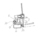
また前記保持アーム7の下面には、前記支点ピン30を中心にして外方に円弧状の案内溝31を形成し、その案内溝31の両端部に同アームを収納状態とキャビン外側へ突出した状態で固定できる位置決め穴31a,31bを設ける構成となっている。一方、前記ブラケット21側には前記各位置決め穴31a.31bに係合する位置決めピン27を備える構成となっている(位置決め機構)。
2 キャビン
3 リヤウインド
4 係止アーム
5 上部フレーム
6 下部フレーム
7 保持アーム
8 ハーフロックストライカ
9 フルロックストライカ
32 クッションゴム(弾性部材)
Claims (1)
- 車両(1)に搭載したキャビン(2)の開閉窓(3)を、キャビンフレーム(6)に対し密着させる全閉状態と、同キャビンフレーム(6)に対し間隙を介した半開状態とに選択保持させるキャビンの窓開閉装置において、
前記窓(3)の左右一側部若しくは上下一側部に、回転式ハンドル(29)と、同回転式ハンドル(29)の操作と一体で且つ前記窓(3)の面に沿って回転する一片状の係止アーム(4)を設ける一方、前記キャビンフレーム(6)には、支点ピン(30)を中心に回動自由に枢着され同キャビンフレーム(6)に沿わせた状態とキャビン外側へ突設させた状態に保持する位置決め機構(31)を備えた保持アーム(7)を設け、同保持アーム(7)の回転基部には、前記係止アーム(4)を係止することにより前記窓(3)を全閉状態に保持させるフルロックストライカ(9)を設けると共に、同保持アーム(7)の先端部には、前記係止アーム(4)を係止することにより前記窓(3)を半開状態に保持させるハーフロックストライカ(8)と同ハーフロックストライカ(8)に前記係止アーム(4)を係止させた時に前記窓(3)を圧着させる弾性部材(32)を備えたことを特徴とするキャビンの窓開閉装置。
Priority Applications (1)
| Application Number | Priority Date | Filing Date | Title |
|---|---|---|---|
| JP2003389569A JP4218506B2 (ja) | 2003-11-19 | 2003-11-19 | キャビンの窓開閉装置 |
Applications Claiming Priority (1)
| Application Number | Priority Date | Filing Date | Title |
|---|---|---|---|
| JP2003389569A JP4218506B2 (ja) | 2003-11-19 | 2003-11-19 | キャビンの窓開閉装置 |
Publications (3)
| Publication Number | Publication Date |
|---|---|
| JP2005146781A JP2005146781A (ja) | 2005-06-09 |
| JP2005146781A5 JP2005146781A5 (ja) | 2008-05-22 |
| JP4218506B2 true JP4218506B2 (ja) | 2009-02-04 |
Family
ID=34696274
Family Applications (1)
| Application Number | Title | Priority Date | Filing Date |
|---|---|---|---|
| JP2003389569A Expired - Fee Related JP4218506B2 (ja) | 2003-11-19 | 2003-11-19 | キャビンの窓開閉装置 |
Country Status (1)
| Country | Link |
|---|---|
| JP (1) | JP4218506B2 (ja) |
Families Citing this family (4)
| Publication number | Priority date | Publication date | Assignee | Title |
|---|---|---|---|---|
| EP2242889B1 (en) * | 2007-12-19 | 2015-10-21 | VKR Holding A/S | Weather shield |
| JP5836085B2 (ja) * | 2011-11-25 | 2015-12-24 | 株式会社クボタ | キャビンの窓開閉装置 |
| JP7110147B2 (ja) * | 2019-03-26 | 2022-08-01 | 株式会社クボタ | キャビンの窓開閉機構及び作業車 |
| KR102598456B1 (ko) * | 2019-05-15 | 2023-11-03 | 엘에스엠트론 주식회사 | 작업차량용 도어 개폐 장치 |
-
2003
- 2003-11-19 JP JP2003389569A patent/JP4218506B2/ja not_active Expired - Fee Related
Also Published As
| Publication number | Publication date |
|---|---|
| JP2005146781A (ja) | 2005-06-09 |
Similar Documents
| Publication | Publication Date | Title |
|---|---|---|
| JP4131865B2 (ja) | ワイパー装置 | |
| JP4835254B2 (ja) | 車両用ドアハンドル装置 | |
| JP4645324B2 (ja) | 車両用ドア | |
| JP4238167B2 (ja) | インサイドハンドル装置 | |
| JP4218506B2 (ja) | キャビンの窓開閉装置 | |
| JP2005146781A5 (ja) | ||
| JP2001280000A (ja) | 車両用開閉体の開閉装置 | |
| US20060249982A1 (en) | Side door arrangement of a motor vehicle | |
| JPH084366A (ja) | 自動車用ドアのアウタサイドハンドル構造 | |
| KR100535505B1 (ko) | 차량 도어 인사이드 핸들 로드의 압축 코일 스프링 적용구조 | |
| JP2525827Y2 (ja) | 自動車用ドアハンドル装置 | |
| JP2003155848A (ja) | 車両用ドアのアウトサイドハンドル装置 | |
| KR100229154B1 (ko) | 가스스프링이 구비된 자동차의 후드힌지구조 | |
| US20230202274A1 (en) | Vehicle rear door handle | |
| KR100534331B1 (ko) | 차량용 후드힌지의 각도조절구조 | |
| JP3917482B2 (ja) | 車両用ワイパ装置 | |
| JP2004251062A (ja) | キャビンの窓開閉装置 | |
| JP3724206B2 (ja) | 車両用収納装置 | |
| JP2951539B2 (ja) | トランクリッドのカーテシスイッチの取付構造 | |
| JP2004076449A (ja) | グローブボックスロック装置 | |
| JP5874277B2 (ja) | 車両用ドアハンドル装置 | |
| JP4203882B2 (ja) | 自動車ドアのチャイルドプルーフ機構 | |
| JP2005335482A (ja) | 窓ガラス開閉機構 | |
| JP2024055516A (ja) | 車両のドアハンドル | |
| KR20190078737A (ko) | 캐빈용 전면창 도어락 |
Legal Events
| Date | Code | Title | Description |
|---|---|---|---|
| A621 | Written request for application examination |
Free format text: JAPANESE INTERMEDIATE CODE: A621 Effective date: 20060227 |
|
| A977 | Report on retrieval |
Free format text: JAPANESE INTERMEDIATE CODE: A971007 Effective date: 20080221 |
|
| A521 | Written amendment |
Free format text: JAPANESE INTERMEDIATE CODE: A523 Effective date: 20080407 |
|
| A131 | Notification of reasons for refusal |
Free format text: JAPANESE INTERMEDIATE CODE: A131 Effective date: 20080422 |
|
| A521 | Written amendment |
Free format text: JAPANESE INTERMEDIATE CODE: A523 Effective date: 20080623 |
|
| TRDD | Decision of grant or rejection written | ||
| A01 | Written decision to grant a patent or to grant a registration (utility model) |
Free format text: JAPANESE INTERMEDIATE CODE: A01 Effective date: 20081021 |
|
| A01 | Written decision to grant a patent or to grant a registration (utility model) |
Free format text: JAPANESE INTERMEDIATE CODE: A01 |
|
| A61 | First payment of annual fees (during grant procedure) |
Free format text: JAPANESE INTERMEDIATE CODE: A61 Effective date: 20081103 |
|
| FPAY | Renewal fee payment (event date is renewal date of database) |
Free format text: PAYMENT UNTIL: 20111121 Year of fee payment: 3 |
|
| R150 | Certificate of patent or registration of utility model |
Free format text: JAPANESE INTERMEDIATE CODE: R150 |
|
| FPAY | Renewal fee payment (event date is renewal date of database) |
Free format text: PAYMENT UNTIL: 20141121 Year of fee payment: 6 |
|
| LAPS | Cancellation because of no payment of annual fees |