JP4115403B2 - 発光体基板及び画像表示装置 - Google Patents
発光体基板及び画像表示装置 Download PDFInfo
- Publication number
- JP4115403B2 JP4115403B2 JP2004040757A JP2004040757A JP4115403B2 JP 4115403 B2 JP4115403 B2 JP 4115403B2 JP 2004040757 A JP2004040757 A JP 2004040757A JP 2004040757 A JP2004040757 A JP 2004040757A JP 4115403 B2 JP4115403 B2 JP 4115403B2
- Authority
- JP
- Japan
- Prior art keywords
- substrate
- light emitter
- anode electrodes
- conductive region
- resistance value
- Prior art date
- Legal status (The legal status is an assumption and is not a legal conclusion. Google has not performed a legal analysis and makes no representation as to the accuracy of the status listed.)
- Expired - Fee Related
Links
- 239000000758 substrate Substances 0.000 title claims description 62
- 229910052751 metal Inorganic materials 0.000 claims description 19
- 239000002184 metal Substances 0.000 claims description 19
- 241001089723 Metaphycus omega Species 0.000 claims 1
- OAICVXFJPJFONN-UHFFFAOYSA-N Phosphorus Chemical compound [P] OAICVXFJPJFONN-UHFFFAOYSA-N 0.000 description 30
- 239000011159 matrix material Substances 0.000 description 27
- 238000000034 method Methods 0.000 description 27
- 239000011521 glass Substances 0.000 description 16
- 238000010586 diagram Methods 0.000 description 14
- 238000004519 manufacturing process Methods 0.000 description 7
- 238000005259 measurement Methods 0.000 description 7
- 230000001133 acceleration Effects 0.000 description 6
- 238000010894 electron beam technology Methods 0.000 description 6
- 238000000206 photolithography Methods 0.000 description 6
- 238000007650 screen-printing Methods 0.000 description 6
- 239000003086 colorant Substances 0.000 description 5
- 230000005684 electric field Effects 0.000 description 5
- 230000007547 defect Effects 0.000 description 4
- 230000000694 effects Effects 0.000 description 4
- 239000002245 particle Substances 0.000 description 4
- 239000000049 pigment Substances 0.000 description 4
- 229910052709 silver Inorganic materials 0.000 description 4
- OKTJSMMVPCPJKN-UHFFFAOYSA-N Carbon Chemical compound [C] OKTJSMMVPCPJKN-UHFFFAOYSA-N 0.000 description 3
- BQCADISMDOOEFD-UHFFFAOYSA-N Silver Chemical compound [Ag] BQCADISMDOOEFD-UHFFFAOYSA-N 0.000 description 3
- 239000012212 insulator Substances 0.000 description 3
- 230000000670 limiting effect Effects 0.000 description 3
- 239000000463 material Substances 0.000 description 3
- 230000008018 melting Effects 0.000 description 3
- 238000002844 melting Methods 0.000 description 3
- 239000002994 raw material Substances 0.000 description 3
- 230000001105 regulatory effect Effects 0.000 description 3
- 239000011347 resin Substances 0.000 description 3
- 229920005989 resin Polymers 0.000 description 3
- 239000004332 silver Substances 0.000 description 3
- 238000002347 injection Methods 0.000 description 2
- 239000007924 injection Substances 0.000 description 2
- 239000000203 mixture Substances 0.000 description 2
- BASFCYQUMIYNBI-UHFFFAOYSA-N platinum Chemical compound [Pt] BASFCYQUMIYNBI-UHFFFAOYSA-N 0.000 description 2
- 229910001925 ruthenium oxide Inorganic materials 0.000 description 2
- WOCIAKWEIIZHES-UHFFFAOYSA-N ruthenium(iv) oxide Chemical compound O=[Ru]=O WOCIAKWEIIZHES-UHFFFAOYSA-N 0.000 description 2
- 229920000049 Carbon (fiber) Polymers 0.000 description 1
- 229910045601 alloy Inorganic materials 0.000 description 1
- 239000000956 alloy Substances 0.000 description 1
- JRPBQTZRNDNNOP-UHFFFAOYSA-N barium titanate Chemical compound [Ba+2].[Ba+2].[O-][Ti]([O-])([O-])[O-] JRPBQTZRNDNNOP-UHFFFAOYSA-N 0.000 description 1
- 229910002113 barium titanate Inorganic materials 0.000 description 1
- 230000000903 blocking effect Effects 0.000 description 1
- 229910052799 carbon Inorganic materials 0.000 description 1
- 239000004917 carbon fiber Substances 0.000 description 1
- 239000002041 carbon nanotube Substances 0.000 description 1
- 229910021393 carbon nanotube Inorganic materials 0.000 description 1
- 239000011248 coating agent Substances 0.000 description 1
- 238000000576 coating method Methods 0.000 description 1
- 239000002772 conduction electron Substances 0.000 description 1
- 230000001276 controlling effect Effects 0.000 description 1
- 229910052802 copper Inorganic materials 0.000 description 1
- 238000005520 cutting process Methods 0.000 description 1
- 230000007423 decrease Effects 0.000 description 1
- 238000007598 dipping method Methods 0.000 description 1
- 239000000835 fiber Substances 0.000 description 1
- 229910002804 graphite Inorganic materials 0.000 description 1
- 239000010439 graphite Substances 0.000 description 1
- 229910052697 platinum Inorganic materials 0.000 description 1
- 229910021420 polycrystalline silicon Inorganic materials 0.000 description 1
- 229920005591 polysilicon Polymers 0.000 description 1
- 239000000843 powder Substances 0.000 description 1
- 238000003980 solgel method Methods 0.000 description 1
- 238000004544 sputter deposition Methods 0.000 description 1
- 238000002834 transmittance Methods 0.000 description 1
- 238000007740 vapor deposition Methods 0.000 description 1
Images
Classifications
-
- H—ELECTRICITY
- H01—ELECTRIC ELEMENTS
- H01J—ELECTRIC DISCHARGE TUBES OR DISCHARGE LAMPS
- H01J31/00—Cathode ray tubes; Electron beam tubes
- H01J31/08—Cathode ray tubes; Electron beam tubes having a screen on or from which an image or pattern is formed, picked up, converted, or stored
- H01J31/10—Image or pattern display tubes, i.e. having electrical input and optical output; Flying-spot tubes for scanning purposes
- H01J31/12—Image or pattern display tubes, i.e. having electrical input and optical output; Flying-spot tubes for scanning purposes with luminescent screen
-
- H—ELECTRICITY
- H01—ELECTRIC ELEMENTS
- H01J—ELECTRIC DISCHARGE TUBES OR DISCHARGE LAMPS
- H01J29/00—Details of cathode-ray tubes or of electron-beam tubes of the types covered by group H01J31/00
- H01J29/02—Electrodes; Screens; Mounting, supporting, spacing or insulating thereof
- H01J29/08—Electrodes intimately associated with a screen on or from which an image or pattern is formed, picked-up, converted or stored, e.g. backing-plates for storage tubes or collecting secondary electrons
- H01J29/085—Anode plates, e.g. for screens of flat panel displays
-
- H—ELECTRICITY
- H01—ELECTRIC ELEMENTS
- H01J—ELECTRIC DISCHARGE TUBES OR DISCHARGE LAMPS
- H01J1/00—Details of electrodes, of magnetic control means, of screens, or of the mounting or spacing thereof, common to two or more basic types of discharge tubes or lamps
- H01J1/02—Main electrodes
- H01J1/30—Cold cathodes, e.g. field-emissive cathode
-
- H—ELECTRICITY
- H01—ELECTRIC ELEMENTS
- H01J—ELECTRIC DISCHARGE TUBES OR DISCHARGE LAMPS
- H01J31/00—Cathode ray tubes; Electron beam tubes
- H01J31/08—Cathode ray tubes; Electron beam tubes having a screen on or from which an image or pattern is formed, picked up, converted, or stored
- H01J31/10—Image or pattern display tubes, i.e. having electrical input and optical output; Flying-spot tubes for scanning purposes
- H01J31/12—Image or pattern display tubes, i.e. having electrical input and optical output; Flying-spot tubes for scanning purposes with luminescent screen
- H01J31/123—Flat display tubes
- H01J31/125—Flat display tubes provided with control means permitting the electron beam to reach selected parts of the screen, e.g. digital selection
- H01J31/127—Flat display tubes provided with control means permitting the electron beam to reach selected parts of the screen, e.g. digital selection using large area or array sources, i.e. essentially a source for each pixel group
-
- H—ELECTRICITY
- H01—ELECTRIC ELEMENTS
- H01J—ELECTRIC DISCHARGE TUBES OR DISCHARGE LAMPS
- H01J2329/00—Electron emission display panels, e.g. field emission display panels
- H01J2329/18—Luminescent screens
- H01J2329/28—Luminescent screens with protective, conductive or reflective layers
Landscapes
- Cathode-Ray Tubes And Fluorescent Screens For Display (AREA)
Description
基板と、
前記基板上に配置された複数の発光体と、
前記基板上に配置され、前記発光体を収容した開口部を有する間隔規定部材と、
前記基板と前記間隔規定部材との間に配置された導電性領域と、
前記発光体を覆い、前記間隔規定部材を介して前記導電性領域により電位が規定される複数のアノード電極と、
を有する発光体基板であって、
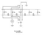
前記導電性領域と前記複数のアノード電極との間の抵抗値(Rz)の最小値よりも、前記複数のアノード電極のうちの隣り合う二つのアノード電極間の抵抗値(Rx)の最小値の方が高いことを特徴とする。
基板と、
前記基板上に配置された複数の発光体と、
前記基板上に配置され、前記発光体を収容した開口部を有する間隔規定部材と導電性領域とを備えた開孔部材と、
前記発光体を覆い、前記間隔規定部材を介して前記導電性領域により電位が規定される複数のアノード電極と、
を有する発光体基板であって、
前記導電性領域と前記複数のアノード電極との間の抵抗値(Rz)の最小値よりも、前記複数のアノード電極のうちの隣り合う二つのアノード電極間の抵抗値(Rx)の最小値の方が高いことを特徴とする。
本発明の第三は、上記本発明第一又は第二の発光体基板と、電子放出素子を配置したリアプレートとを有する画像表示装置である。
(1)放電時の電流制限が十分発揮されるような抵抗値であること、
(2)画像表示のために電子放出素子から注入される電流により電圧降下しない程度の抵抗値であること、
が求められる。
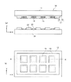
図1(a)、図4に示す表示パネルを備えた画像表示装置を作製した。
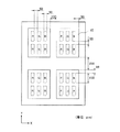
図6(a)に示す構成の表示パネルを備えた画像表示装置を作製した。図6(b)は、(a)のフェースプレート10をリアプレート21側から見た平面模式図であり、(a)は(b)のC−C’断面に相当する。また、図6(c)に(b)のD−D’断面を示す。
図7(a)に示す構成の表示パネルを備えた画像表示装置を作製した。図7(b)は、(a)のフェースプレート10をリアプレート21側から見た平面模式図であり、(a)は(b)のE−E’断面に相当する。また、図7(c)に(b)のF−F’断面を示す。
図8(a)に示す構成の表示パネルを備えた画像表示装置を作製した。図中、25はブラックマトリクス、26は絶縁部材である。また、図8(b)は、(a)のフェースプレート10をリアプレート21側から見た平面模式図であり、(a)は(b)のG−G’断面に相当する。また、図8(c)に(b)のH−H’断面を示す。
図9(a)に示す構成の表示パネルを備えた画像表示装置を作製した。図9(b)は、(a)のフェースプレート10をリアプレート21側から見た平面模式図であり、(a)は(b)のI−I’断面に相当する。また、図9(c)に(b)のJ−J’断面を示す。
図10(a)に示す構成の表示パネルを備えた画像表示装置を作製した。図中、27は金属板、28は高抵抗部材である。図10(b)は、(a)のフェースプレート10をリアプレート21側から見た平面模式図であり、(a)は(b)のK−K’断面に相当する。また、図10(c)に(b)のL−L’断面を示す。
図11に示すように、導電性膜15をR,G,Bの3絵素を一組とする1画素を覆う構成とした以外は、実施例1と同様にして画像表示装置を作製した。
図12に示すように、導電性膜15を2画素を覆う構成とした以外は、実施例1と同様にして画像表示装置を作製した。
11 基板
12 導電性領域
13 間隔規定部材
14 発光体
15 導電性膜
16 高圧電源
17 開口部材
18 側壁
19 電極パッド
21 リアプレート
22 列方向配線
23 素子
24 行方向配線
25 ブラックマトリクス
26 絶縁部材
27 金属板
28 高抵抗部材
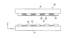
31 リアプレート
32 列方向配線
33 素子
34 行方向配線
40 フェースプレート
41 基板
43 間隔規定部材
44 蛍光体
45 メタルバック
46 高圧電源
47 蛍光体層
48 側壁
Claims (14)
- 基板と、
前記基板上に配置された複数の発光体と、
前記基板上に配置され、前記発光体を収容した開口部を有する間隔規定部材と、
前記基板と前記間隔規定部材との間に配置された導電性領域と、
前記発光体を覆い、前記間隔規定部材を介して前記導電性領域により電位が規定される複数のアノード電極と、
を有する発光体基板であって、
前記導電性領域と前記複数のアノード電極との間の抵抗値(Rz)の最小値よりも、前記複数のアノード電極のうちの隣り合う二つのアノード電極間の抵抗値(Rx)の最小値の方が高いことを特徴とする発光体基板。 - 前記導電性領域は、前記発光体と基板との間を除く位置に配置されていることを特徴とする請求項1に記載の発光体基板。
- 前記間隔規定部材が、隣り合うアノード電極間で分断されていることを特徴とする請求項1または2に記載の発光体基板。
- 基板と、
前記基板上に配置された複数の発光体と、
前記基板上に配置され、前記発光体を収容した開口部を有する間隔規定部材と導電性領域とを備えた開孔部材と、
前記発光体を覆い、前記間隔規定部材を介して前記導電性領域により電位が規定される複数のアノード電極と、
を有する発光体基板であって、
前記導電性領域と前記複数のアノード電極との間の抵抗値(Rz)の最小値よりも、前記複数のアノード電極のうちの隣り合う二つのアノード電極間の抵抗値(Rx)の最小値の方が高いことを特徴とする発光体基板。 - 前記間隔規定部材の前記基板側に前記導電性領域が設けられていることを特徴とする請求項4に記載の発光体基板。
- 前記間隔規定部材は、隣接する前記アノード電極間に介在する絶縁層を有することを特徴とする請求項1、2または5に記載の発光体基板。
- 前記開孔部材が、隣接するアノード電極間で分断されていることを特徴とする請求項1、2または5に記載の発光体基板。
- 前記開孔部材が、前記導電性領域である金属板と、該金属板を覆う、前記間隔規定部材である高抵抗部材とで構成されていることを特徴とする請求項4に記載の発光体基板。
- 前記複数のアノード電極に供給する電位を前記導電性領域に供給する電極パッドを有し、前記導電性領域から前記複数のアノード電極の各々までの抵抗値(Rz)よりも、前記導電性領域から前記電極パッドまでの抵抗値(Rp)の方が低いことを特徴とする請求項1乃至8のいずれか1項に記載の発光体基板。
- 前記導電性領域と前記複数のアノード電極との間の抵抗値の最小値が500Ωより大きいことを特徴とする請求項1乃至9のいずれか1項に記載の発光体基板。
- 前記導電性領域と前記複数のアノード電極との間の抵抗値の最小値が1MΩより小さいことを特徴とする請求項1乃至9のいずれか1項に記載の発光体基板。
- 前記複数のアノード電極のうち、隣り合う二つのアノード電極間の抵抗値の最小値が1kΩより大きいことを特徴とする請求項1乃至11のいずれか1項に記載の発光体基板。
- 前記複数のアノード電極のうち、隣り合う二つのアノード電極間の抵抗値の最小値が1MΩより大きいことを特徴とする請求項1乃至11のいずれか1項に記載の発光体基板。
- 発光体基板と、電子放出素子を複数備えたリアプレートとを有する画像表示装置であって、該発光基板が請求項1乃至13のいずれか1項に記載の発光体基板であることを特徴とする画像表示装置。
Priority Applications (5)
| Application Number | Priority Date | Filing Date | Title |
|---|---|---|---|
| JP2004040757A JP4115403B2 (ja) | 2004-02-18 | 2004-02-18 | 発光体基板及び画像表示装置 |
| US11/043,076 US7312770B2 (en) | 2004-02-18 | 2005-01-27 | Substrate having a light emitter and image display device |
| CNB2005100083791A CN100428501C (zh) | 2004-02-18 | 2005-02-17 | 具有发光体的基板以及图像显示装置 |
| KR1020050013384A KR100620961B1 (ko) | 2004-02-18 | 2005-02-18 | 발광체를 가진 기판 및 화상표시장치 |
| US11/937,574 US7679280B2 (en) | 2004-02-18 | 2007-11-09 | Substrate having a light emitter and image display device |
Applications Claiming Priority (1)
| Application Number | Priority Date | Filing Date | Title |
|---|---|---|---|
| JP2004040757A JP4115403B2 (ja) | 2004-02-18 | 2004-02-18 | 発光体基板及び画像表示装置 |
Publications (3)
| Publication Number | Publication Date |
|---|---|
| JP2005235470A JP2005235470A (ja) | 2005-09-02 |
| JP2005235470A5 JP2005235470A5 (ja) | 2008-02-07 |
| JP4115403B2 true JP4115403B2 (ja) | 2008-07-09 |
Family
ID=34836392
Family Applications (1)
| Application Number | Title | Priority Date | Filing Date |
|---|---|---|---|
| JP2004040757A Expired - Fee Related JP4115403B2 (ja) | 2004-02-18 | 2004-02-18 | 発光体基板及び画像表示装置 |
Country Status (4)
| Country | Link |
|---|---|
| US (2) | US7312770B2 (ja) |
| JP (1) | JP4115403B2 (ja) |
| KR (1) | KR100620961B1 (ja) |
| CN (1) | CN100428501C (ja) |
Families Citing this family (19)
| Publication number | Priority date | Publication date | Assignee | Title |
|---|---|---|---|---|
| JP2006114403A (ja) * | 2004-10-15 | 2006-04-27 | Toshiba Corp | 画像表示装置 |
| JP4551755B2 (ja) * | 2004-12-24 | 2010-09-29 | キヤノン株式会社 | 画像表示装置 |
| JP2006185614A (ja) * | 2004-12-24 | 2006-07-13 | Toshiba Corp | 表示装置 |
| JP4750413B2 (ja) * | 2004-12-27 | 2011-08-17 | キヤノン株式会社 | 画像表示装置 |
| JP4449835B2 (ja) * | 2005-06-27 | 2010-04-14 | ソニー株式会社 | 平面型表示装置用のアノードパネルの製造方法 |
| US20070018559A1 (en) * | 2005-07-20 | 2007-01-25 | Jeng-Ywan Jeng | Printer light source device |
| TW200725109A (en) * | 2005-12-29 | 2007-07-01 | Ind Tech Res Inst | Field emission backlight module |
| US8018133B2 (en) | 2006-12-25 | 2011-09-13 | Canon Kabushiki Kaisha | Image display apparatus |
| JP2008159449A (ja) * | 2006-12-25 | 2008-07-10 | Canon Inc | 表示装置 |
| US8169133B2 (en) | 2006-12-27 | 2012-05-01 | Canon Kabushiki Kaisha | Image display apparatus, manufacturing method of image display apparatus, and functional film |
| US8058789B2 (en) * | 2007-02-05 | 2011-11-15 | Vu1 Corporation | Cathodoluminescent phosphor lamp having extraction and diffusing grids and base for attachment to standard lighting fixtures |
| US8007333B2 (en) * | 2008-06-06 | 2011-08-30 | Xerox Corporation | Method of forming field emission light emitting device including the formation of an emitter within a nanochannel in a dielectric matrix |
| JP2009295532A (ja) * | 2008-06-09 | 2009-12-17 | Canon Inc | 発光体基板及びそれを用いた画像表示装置 |
| JP5281478B2 (ja) * | 2009-05-15 | 2013-09-04 | キヤノン株式会社 | 電子装置、回路基板、高圧電源装置、および、電子部品と圧電素子とを回路基板に半田付けする方法 |
| WO2014050183A1 (ja) * | 2012-09-28 | 2014-04-03 | シャープ株式会社 | 蛍光体含有封止材の製造方法、蛍光体含有封止材、発光装置の製造方法およびディスペンサー |
| KR101434953B1 (ko) * | 2013-02-15 | 2014-08-28 | 지스마트 주식회사 | 투명전광판을 구비한 탑승교 |
| KR101512661B1 (ko) * | 2013-12-10 | 2015-04-17 | 지스마트 주식회사 | 창틀에 설치가능한 복층 구조를 갖는 투명전광판 및 그 제조방법 |
| US11915623B2 (en) | 2020-06-09 | 2024-02-27 | Wuhan China Star Optoelectronics Semiconductor Display Technology Co., Ltd. | Flexible display panel, manufacturing method thereof, and flexible display device |
| CN111724680B (zh) * | 2020-06-09 | 2022-02-01 | 武汉华星光电半导体显示技术有限公司 | 柔性显示面板及其制备方法、柔性显示装置 |
Family Cites Families (16)
| Publication number | Priority date | Publication date | Assignee | Title |
|---|---|---|---|---|
| CN1161646C (zh) * | 1994-06-02 | 2004-08-11 | 株式会社半导体能源研究所 | 有源矩阵显示器和电光元件 |
| FR2725072A1 (fr) | 1994-09-28 | 1996-03-29 | Pixel Int Sa | Protection electrique d'une anode d'ecran plat de visualisation |
| FR2732160B1 (fr) * | 1995-03-22 | 1997-06-13 | Pixtech Sa | Anode d'ecran plat de visualisation a bandes resistives |
| JPH09321548A (ja) * | 1996-05-31 | 1997-12-12 | S I I R D Center:Kk | 半導体集積回路装置 |
| TW350059B (en) | 1996-07-23 | 1999-01-11 | Futaba Denshi Kogyo Kk | Field emission type image display panel and method of driving the same |
| JP3199682B2 (ja) | 1997-03-21 | 2001-08-20 | キヤノン株式会社 | 電子放出装置及びそれを用いた画像形成装置 |
| JP4258860B2 (ja) * | 1998-09-04 | 2009-04-30 | セイコーエプソン株式会社 | 光伝達手段を備えた装置 |
| JP2000251797A (ja) | 1999-02-25 | 2000-09-14 | Canon Inc | 画像形成装置 |
| US6771236B1 (en) | 1999-03-05 | 2004-08-03 | Sony Corporation | Display panel and display device to which the display panel is applied |
| JP4304809B2 (ja) | 1999-03-05 | 2009-07-29 | ソニー株式会社 | 表示用パネル及びこれを用いた表示装置 |
| JP2001126633A (ja) | 1999-10-22 | 2001-05-11 | Canon Inc | 画像表示装置及び画像表示装置の駆動方法 |
| JP4670137B2 (ja) * | 2000-03-10 | 2011-04-13 | ソニー株式会社 | 平面型表示装置 |
| JP2002164007A (ja) * | 2000-11-24 | 2002-06-07 | Toshiba Corp | 表示装置 |
| JP2002175764A (ja) | 2000-12-07 | 2002-06-21 | Sony Corp | 表示用パネル及びこれを用いた表示装置 |
| US8089888B2 (en) * | 2001-12-10 | 2012-01-03 | Qualcomm Incorporated | Method and apparatus for testing traffic and auxiliary channels in a wireless data communication system |
| JP2004047561A (ja) * | 2002-07-09 | 2004-02-12 | Olympus Corp | 光導電スイッチモジュールおよびその製造方法 |
-
2004
- 2004-02-18 JP JP2004040757A patent/JP4115403B2/ja not_active Expired - Fee Related
-
2005
- 2005-01-27 US US11/043,076 patent/US7312770B2/en not_active Expired - Fee Related
- 2005-02-17 CN CNB2005100083791A patent/CN100428501C/zh not_active Expired - Fee Related
- 2005-02-18 KR KR1020050013384A patent/KR100620961B1/ko not_active Expired - Fee Related
-
2007
- 2007-11-09 US US11/937,574 patent/US7679280B2/en not_active Expired - Fee Related
Also Published As
| Publication number | Publication date |
|---|---|
| JP2005235470A (ja) | 2005-09-02 |
| KR100620961B1 (ko) | 2006-09-14 |
| US7312770B2 (en) | 2007-12-25 |
| US20050179398A1 (en) | 2005-08-18 |
| US20080067913A1 (en) | 2008-03-20 |
| CN100428501C (zh) | 2008-10-22 |
| KR20060042949A (ko) | 2006-05-15 |
| CN1658403A (zh) | 2005-08-24 |
| US7679280B2 (en) | 2010-03-16 |
Similar Documents
| Publication | Publication Date | Title |
|---|---|---|
| JP4115403B2 (ja) | 発光体基板及び画像表示装置 | |
| US20120013582A1 (en) | Image display apparatus | |
| JP4027386B2 (ja) | 発光スクリーン構造及び画像形成装置 | |
| US7821191B2 (en) | Field emission display | |
| JP5317658B2 (ja) | 発光基板及びそれを用いた表示装置 | |
| KR100742096B1 (ko) | 화상 표시 장치 | |
| US8072133B2 (en) | Light emitter substrate and image displaying apparatus using the same | |
| US20080157666A1 (en) | Image display apparatus, manufacturing method of image display apparatus, and functional film | |
| US20110254434A1 (en) | Image display apparatus | |
| JP5183807B2 (ja) | 発光スクリーン及び画像表示装置 | |
| JP2005268109A (ja) | 発光体基板およびそれを用いた画像表示装置 | |
| JP5590830B2 (ja) | 発光体基板及びこれを用いた画像表示装置 | |
| US20100148670A1 (en) | Electron source substrate and image display apparatus | |
| EP2249371B1 (en) | Light-emitting substrate including light-emitting members and image display apparatus including the light-emitting substrate | |
| US8253319B2 (en) | Light emitter substrate with improved withstand discharge characteristics, and image displaying apparatus using the same | |
| US20110254821A1 (en) | Image display apparatus | |
| JP2008181857A (ja) | 画像表示装置、画像表示装置の製造方法、及び、機能付きフィルム | |
| TW200539213A (en) | Image display device | |
| JP2006092963A (ja) | 画像表示装置 | |
| JP2012018884A (ja) | 発光スクリーンおよび発光スクリーンの製造方法 | |
| JP2008282759A (ja) | 平面型画像表示装置及びその製造方法 | |
| JP2005259517A (ja) | 表示装置 | |
| JP2007035494A (ja) | 平面ディスプレイ | |
| JP2011238556A (ja) | 発光スクリーン及び画像表示装置の製造方法 | |
| JP2005235471A (ja) | 画像表示装置 |
Legal Events
| Date | Code | Title | Description |
|---|---|---|---|
| A621 | Written request for application examination |
Free format text: JAPANESE INTERMEDIATE CODE: A621 Effective date: 20061225 |
|
| A521 | Request for written amendment filed |
Free format text: JAPANESE INTERMEDIATE CODE: A523 Effective date: 20071214 |
|
| A131 | Notification of reasons for refusal |
Free format text: JAPANESE INTERMEDIATE CODE: A131 Effective date: 20080226 |
|
| A521 | Request for written amendment filed |
Free format text: JAPANESE INTERMEDIATE CODE: A523 Effective date: 20080317 |
|
| TRDD | Decision of grant or rejection written | ||
| A01 | Written decision to grant a patent or to grant a registration (utility model) |
Free format text: JAPANESE INTERMEDIATE CODE: A01 Effective date: 20080408 |
|
| A61 | First payment of annual fees (during grant procedure) |
Free format text: JAPANESE INTERMEDIATE CODE: A61 Effective date: 20080415 |
|
| FPAY | Renewal fee payment (event date is renewal date of database) |
Free format text: PAYMENT UNTIL: 20110425 Year of fee payment: 3 |
|
| R150 | Certificate of patent or registration of utility model |
Free format text: JAPANESE INTERMEDIATE CODE: R150 |
|
| FPAY | Renewal fee payment (event date is renewal date of database) |
Free format text: PAYMENT UNTIL: 20110425 Year of fee payment: 3 |
|
| FPAY | Renewal fee payment (event date is renewal date of database) |
Free format text: PAYMENT UNTIL: 20130425 Year of fee payment: 5 |
|
| FPAY | Renewal fee payment (event date is renewal date of database) |
Free format text: PAYMENT UNTIL: 20130425 Year of fee payment: 5 |
|
| FPAY | Renewal fee payment (event date is renewal date of database) |
Free format text: PAYMENT UNTIL: 20140425 Year of fee payment: 6 |
|
| LAPS | Cancellation because of no payment of annual fees |


