JP3787489B2 - Method and apparatus for breaking brittle substrate - Google Patents
Method and apparatus for breaking brittle substrate Download PDFInfo
- Publication number
- JP3787489B2 JP3787489B2 JP2000302059A JP2000302059A JP3787489B2 JP 3787489 B2 JP3787489 B2 JP 3787489B2 JP 2000302059 A JP2000302059 A JP 2000302059A JP 2000302059 A JP2000302059 A JP 2000302059A JP 3787489 B2 JP3787489 B2 JP 3787489B2
- Authority
- JP
- Japan
- Prior art keywords
- substrate
- brittle substrate
- brittle
- break
- scribe line
- Prior art date
- Legal status (The legal status is an assumption and is not a legal conclusion. Google has not performed a legal analysis and makes no representation as to the accuracy of the status listed.)
- Expired - Fee Related
Links
Images


Classifications
-
- H—ELECTRICITY
- H01—ELECTRIC ELEMENTS
- H01L—SEMICONDUCTOR DEVICES NOT COVERED BY CLASS H10
- H01L21/00—Processes or apparatus adapted for the manufacture or treatment of semiconductor or solid state devices or of parts thereof
- H01L21/70—Manufacture or treatment of devices consisting of a plurality of solid state components formed in or on a common substrate or of parts thereof; Manufacture of integrated circuit devices or of parts thereof
- H01L21/77—Manufacture or treatment of devices consisting of a plurality of solid state components or integrated circuits formed in, or on, a common substrate
- H01L21/78—Manufacture or treatment of devices consisting of a plurality of solid state components or integrated circuits formed in, or on, a common substrate with subsequent division of the substrate into plural individual devices
-
- C—CHEMISTRY; METALLURGY
- C03—GLASS; MINERAL OR SLAG WOOL
- C03B—MANUFACTURE, SHAPING, OR SUPPLEMENTARY PROCESSES
- C03B33/00—Severing cooled glass
- C03B33/02—Cutting or splitting sheet glass or ribbons; Apparatus or machines therefor
- C03B33/023—Cutting or splitting sheet glass or ribbons; Apparatus or machines therefor the sheet or ribbon being in a horizontal position
- C03B33/033—Apparatus for opening score lines in glass sheets
-
- B—PERFORMING OPERATIONS; TRANSPORTING
- B65—CONVEYING; PACKING; STORING; HANDLING THIN OR FILAMENTARY MATERIAL
- B65G—TRANSPORT OR STORAGE DEVICES, e.g. CONVEYORS FOR LOADING OR TIPPING, SHOP CONVEYOR SYSTEMS OR PNEUMATIC TUBE CONVEYORS
- B65G2249/00—Aspects relating to conveying systems for the manufacture of fragile sheets
- B65G2249/04—Arrangements of vacuum systems or suction cups
- B65G2249/045—Details of suction cups suction cups
Landscapes
- Chemical & Material Sciences (AREA)
- Engineering & Computer Science (AREA)
- Materials Engineering (AREA)
- Organic Chemistry (AREA)
- General Physics & Mathematics (AREA)
- Condensed Matter Physics & Semiconductors (AREA)
- Physics & Mathematics (AREA)
- Manufacturing & Machinery (AREA)
- Computer Hardware Design (AREA)
- Microelectronics & Electronic Packaging (AREA)
- Power Engineering (AREA)
- Re-Forming, After-Treatment, Cutting And Transporting Of Glass Products (AREA)
- Processing Of Stones Or Stones Resemblance Materials (AREA)
- Dicing (AREA)
- Perforating, Stamping-Out Or Severing By Means Other Than Cutting (AREA)
Description
【0001】
【発明の属する技術分野】
本発明は、スクライブラインが形成された脆性基板をそのスクライブラインに沿って分断するためのブレイク装置に関する。
脆性基板としては半導体ウェハ、ガラス基板、貼り合わせガラス基板やセラミック基板などが含まれる。
【0002】
【従来の技術】
図1に単板の脆性基板に対する分断システムを示している。スクライブ装置1にて、テーブル2上の脆性基板3に対し、所定の切り込み圧を加えた状態でカッターホイールチップ4を転動させることにより、脆性基板表面にスクライブラインSを形成する。
【0003】
その脆性基板3を反転させた状態でブレイク装置5のテーブル6上にクッションシート7を挟んでセットする。脆性基板下面にあるスクライブラインSの上方には、スクライブライン方向に延在する棒状のブレイクバー8が位置しており、このブレイクバー8をシリンダ9の駆動により下降させて脆性基板3を上方から押圧して、脆性基板3を弾性体のクッションシート7上で僅かにV字状に撓ませることにより、スクライブラインSのクラック(分断に寄与する垂直成分のクラック)を伸長させて脆性基板3をスクライブラインSに沿って分断する。
【0004】
図2は、液晶パネルのごとき貼り合わせガラス基板に対するブレイク方法を示している。
1.スクライブ装置1'にて、貼り合わせガラス基板3′のA面(この図ではA面が上側のガラス基板)に対してスクライブする(図2a)。
2.次にブレイク装置5'において、反転させた貼り合わせガラス基板のB面に対してブレイクバー8を押圧して下側のA面をブレイクする(図2b)。
3.その貼り合わせガラス基板3′を第2のスクライブ装置1”に移送し(または前記スクライブ装置1'に戻し)、B面に対してスクライブする(液晶パネルではガラス辺の一端に端子を形成する関係上、A面とB面とでスクライブ位置が互いにずれている(図2c))。
4.次に第2のブレイク装置5”(または前記ブレイク装置5')において、再度反転させた貼り合わせガラス基板3′のA面に対してブレイクバー8を押圧して下側のB面をブレイクする(図2d)。
【0005】
【発明が解決しようとする課題】
しかしながら、上述のごとく、スクライブ済みの脆性基板3をスクライブ装置からブレイク装置へ搬送する際に、脆性基板3の反転工程が不可欠であった。その反転を行うには、図3(a)のごとく、スクライブ済みの脆性基板3をロボットアーム10などで別の架台11などに一旦置き、次に図3(b)のようにその脆性基板3を今度は前記ロボットアーム10で下から持ち上げて(つまり持ち替えて)、図3(c)に示すようにブレイク装置のテーブル6にセットしていた。そのため、このような反転機構が必要となるだけでなく、作業効率も低いものであった。
又、従来はスクライブおよびブレイクのためにそれぞれ専用の反転装置を必要としたため、システムが大型化しコストも高くついた。
【0006】
本発明は、上述した課題を解決するためになされたものであり、スクライブ後スクライブ面を上向きにしたまま、ブレイクを行うことができ、もってスクライブ後の脆性基板の反転工程を不要とし、併せて、脆性基板のスクライブおよびブレイクを一つのテーブル上で行えるブレイク方法およびブレイク装置を提供することを目的とする。
【0007】
【課題を解決するための手段】
本発明は、脆性基板の上面に形成したスクライブラインに対し、そのスクライブラインを中央に含むようにして所定幅の領域を覆う閉空間を作り、その閉空間を減圧することにより、脆性基板を逆V字状に僅かに湾曲させてブレイクを行わせることを特徴とする。
【0008】
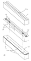
【発明の実施の形態】
図4は、本発明のブレイク方法に用いるブレイクバー25の組み立て図を示している。上図にあるように、アルミ材による柱状直方体21を用いる。その寸法は、加工対象に応じ、長さ300mm〜1000mm、幅10mm〜30mm、厚み10mm〜50mmのいずれかの値とする。その柱状直方体21の上面中央に幅6mm、深さ0.5mmの溝21aを柱方向に形成する。
【0009】
次いで中図にあるように、その溝21aの両端と、それぞれの両端から所定長内側とに、計4個の弾性体による仕切片22を埋め込む。それらの各仕切片22の厚さは前記溝21aの深さと同じにする。これらの仕切片22により、溝21aは直方体21の長手軸方向に3つの区間に区分けされる。それらの各区間における溝の底面から当該柱状直方体21の下面まで貫通する吸引孔23をそれぞれ形成する。
【0010】
そして下図にあるように、柱状直方体21の上面を弾性体による5mm厚の吸引シート24を接合する。これにより、上記の溝21aに3つの閉区間が形成される。そして、これらの3つの閉区間に対応して、吸引シート24の上面から下面に貫通する切り目24aをそれぞれの閉区間に形成する。このようにしてブレイクバー25を得る。ここでは切り目24aを前記3つの閉区間に対応して3本に区切って形成したが、1本の連続した切り目としても差し支えない。
【0011】
吸引シート24および仕切片22としては、経年劣化の少ない、高発泡シリコーンスポンジシート(スプリングかたさ試験(日本ゴム協会標準規格:SRIS 0101-1968)で5〜30のもの)を使用したが、適当な弾性係数を有する材質であればよい。
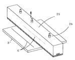
【0012】
ブレイク時には図5に示すように、吸引シート24の面を脆性基板3に当接させて用いる。上記吸引孔23の開口部に設けたプラグ26に真空引きを行うためのチューブが接続される。
【0013】
図5は、ブレイクバー長が脆性基板3のスクライブラインSの長さにほぼ等しい場合であり、このときは、3つのプラグ26から同時に真空引きを行うが、図6のように、脆性基板3″のスクライブライン長がブレイクバー長より短いときは、中央のプラグ26により、真空引きを行う。
【0014】
図4ではブレイクバーの閉区間が3つの場合を説明したが、閉区間を4〜20個として、脆性材料のスクライブライン長等の分断条件に合わせて、個々の区間の真空圧を個別に制御することがのぞましい。
【0015】
図7は、図5(図6でも同じ)のプラグ26の個所における垂直断面図を示している。脆性基板3のスクライブラインSに上記切り目24aのラインをほぼ合致させる。ここで注目すべきことは、スクライブラインSは脆性基板3の下面ではなく、上面にあり、又、脆性基板3とテーブル6との間にクッションシートが不要であることである。
【0016】
次に図8に示すように、プラグ26から真空引きを行うと、吸引シート24は逆V字状に僅かに変形し、それに追随して脆性基板3も変形し、この変形により、スクライブラインSのクラックが下方に成長して脆性基板3が分断される。吸引シート24に切り目24aを形成した理由は、図7のように、ブレイクバー25をその自重で脆性基板3に当接している状態で、両者の接合面で僅かながら存在する空隙部に残る空気を吸い込むことにより、両者間の吸引力を増すためである。この切り目24aに替えて、小孔を一列に設けてもよく、又、脆性基板3と吸引シート24との密着性が良い場合にはこのような切り目を備えなくてもほぼ期待できるような吸引力が得られる。
【0017】
図9は上述したブレイクバー25を用いたブレイク装置30の1実施形態を示した斜視図である。テーブル6は、Y方向に移動するとともに90度及びθ回転可能であり、そのテーブル面には脆性基板3が吸引固定される。ブリッジ31は、テーブル6上をまたぐようにして設けられたものであり、両側の支持板と、それに支持された水平X方向に延在する天板31aからなる。
【0018】
その天板31aの中央にエアシリンダ32が設けられ、そのエアシリンダ32から下方に向くシリンダ軸33の下端部がブレイクバー25を上面中央部で支持している。そのエアシリンダ32の駆動により、ブレイクバー25は上下動するが、下降時にブレイクバー25が脆性基板3に衝突しないように、部分拡大図のごとく、シリンダ軸33に固定された係止片34と、一方端が天板31aに固定されたL字型のストッパー35と、係止片34に設けたネジ穴に螺合し、下端部がストッパー35の水平部に上方から当接するネジ36とからなるストッパー機構37を備える。そのネジ36を、天板31aに設けた穴Qを通じてネジ回しなどで回すことにより、ブレイクバー25の下降位置をガラス板3の板厚に応じて調整する。尚、このストッパー機構37に替えて、ブレイクバー25が緩やかに下降できるように適当な制動機構を備えるようにしてもよい。
【0019】
ブレイクバー25は、その昇降時に平行移動させるためのガイド棒38が設けられている。3つ設けたプラグ26の内、中央のプラグはバルブV1を介して真空ポンプにつながれ、両端二つのプラグ26はバルブV2を介して真空ポンプにつながれる。図5のようなブレイク時にはバルブV1、V2が共に開にされ、図6のようなブレイク時にはバルブV1のみが開にされる。
【0020】
真空吸引時の真空圧は、ゲージ圧で−1.33×10²Pa(−1mmHg)〜−8.64×10⁴Pa(−650mmHg)の範囲に調節可能であり、一方、脆性基板3をテーブル6に吸引固定するための真空圧はゲージ圧で−1.33×10²Pa(−1mmHg)以下であり、テーブル6に形成した吸引穴はφ2mmであった。このガラス板固定用の真空圧を、ブレイク用の真空圧よりも小さく(より大気圧に近い)しておけば、スクライブラインの直下に吸引穴が位置していてもブレイクに差し支えない。
【0021】
図10は、上記ブレイク装置30を採用した脆性基板加工のシステム図を示す。給材搬送機などにより、貼り合わせガラス基板3′は、スクライブ装置S1のテーブルにセットされ、上側のA面に対してスクライブされる。スクライブ装置の機構については図11にて述べる。
【0022】
A面がスクライブされた貼り合わせガラス基板3′は、搬送機により、A面ブレイク装置B1(図9で示したブレイク装置)のテーブルにA面を上側にしたままでセットされ、本発明のブレイク法に従ってA面がブレイクされる。
【0023】
その貼り合わせガラス基板は、反転機により表裏を反転させてから第2のB面スクライブ装置S2のテーブルにセットされる(システムをスクライブ装置S1およびブレイク装置B1のみで構成するときはそのスクライブ装置S1に戻す)。そして上側に位置するB面に対してスクライブされる。
【0024】
B面がスクライブされた貼り合わせガラス基板は、搬送機により、第2のB面ブレイク装置B2(又は前記ブレイク装置B1)のテーブルにB面を上側にしたままでセットされ、B面がブレイクされる。これにて貼り合わせガラス基板の加工は終了し、除材搬送機により、次工程へ搬出される。
【0025】
図11は、脆性基板のスクライバーの装置でブレイクをも行えるようにしたスクライブ兼ブレイク装置40の1実施形態を示している。テーブル6上をまたぐようにして設けられたブリッジ41は、両側の支持柱とX方向に延在するガイドバー42とからなり、そのガイドバー42には、同バー方向にガイド42aが設けられている。スクライブヘッド43はホルダー支持体44を介して前記ガイド42aに沿って移動自在に設けられ、そのスクライブヘッド43の下部には、カッターホイールチップ45を回転自在に保持するチップホルダー46が設けられている。
【0026】
以上の要素からなるスクライブ機構の背後には、図9で説明したブリッジ31を含むブレイク機構が位置する。
【0027】
そのブレイク機構の背後には、脆性基板3に記されたアライメントマークを認識するために一対のカメラ51、52を備え、そのカメラで捕らえた画像はモニター53、54に表示されると共に、画像認識装置にて、アライメントマークが画像認識され、それの位置データが演算される。
【0028】
既述したように、本発明によれば、スクライブ後に脆性基板を反転させることなくブレイクを行え、かつ、そのブレイク装置においては図1で示したようなクッションシート7が不要なためにスクライブを行ったテーブルでブレイクをも行える。
【0029】
図12は、上記のスクライブ兼ブレイク装置40を採用した貼り合わせガラス基板の加工のシステム図を示す。給材搬送機などにより、貼り合わせガラス基板3′は、スクライブ兼ブレイク装置SB1のテーブルにセットされ、上側のA面に対してスクライブされた後、続いてブレイクも行われる。
【0030】
A面がスクライブおよびブレイクされた貼り合わせガラス基板3'は、表裏を反転させてから第2のスクライブ兼ブレイク装置SB2のテーブルにセットされる(システムをスクライブ兼ブレイク装置SB1のみで構成するときはそのスクライブ兼ブレイク装置SB1に戻す)。そして、上側に位置しているB面に対してスクライブおよびブレイクが行われ、次工程へ搬出される。
【0031】
単板の脆性基板及び貼り合わせ脆性基板を完全分断させるためには、分断条件および次行程の生産方式による条件により複数のブレイク装置が必要となる。例えば、単板の脆性基板のブレイクにおいては、第1の方向のブレイクと第1の方向と脆性基板の同一面上で90゜の角度を持つ第2の方向のブレイクに、それぞれ個別の本発明のブレイク装置を用いる。また、貼り合わせ脆性基板を短冊に分断して、次行程へ送る場合には、次行程へ送るまでに、脆性基板の表裏面に対して、それぞれ個別の本発明のブレイク装置を用いる。
【0032】
尚、本実施形態で採用した溝21aや吸引シート24(図4)の寸法は単なる一例であり、本発明の実施に適う寸法は以下の通りである。
溝の幅 :3mm〜10mm
溝の深さ :0.1mm〜1mm
シートの厚さ:1mm〜8mm
【0033】
【発明の効果】
以上説明したように、本発明は、スクライブ後の脆性基板を反転させずに、つまりスクライブラインを上側にしてブレイクできるので、脆性基板の加工のシステム形態を小さくでき、又、反転工程が不要となることにより、全加工に要するタイムを短縮できる。又、ブレイクの際には、脆性基板とテーブルとの間のクッション材が不要なため、スクライブ装置のテーブル上でブレイクも併せて行うことができ、その場合には、スクライブ済みの脆性基板をスクライブ装置からブレイク装置へ搬送する機構も不要となり、システムサイズおよび加工タイムを小さくできる。
【図面の簡単な説明】
【図1】 単板の脆性基板に対する従来のスクライブおよびブレイクを示した図
【図2】 貼り合わせガラス基板に対する従来のスクライブおよびブレイクを示した図
【図3】 脆性基板の表裏を反転させる反転工程を示した図
【図4】 本発明に係わるブレイクバーの組立図
【図5】 図4のブレイクバーのブレイク時の様子を示した図
【図6】 脆性基板のサイズが小さい時のブレイクの様子を示した図
【図7】 図5のプラグにおける縦断面図
【図8】 図5におけるブレイク時の様子を示した図
【図9】 上記ブレイクバーを採用したブレイク装置の1実施形態を示した斜視図
【図10】 上記ブレイク装置を用いて構成した脆性基板の加工のシステム図
【図11】 従来のスクライブ装置に図9のブレイク機構を具備したスクライブ兼ブレイク装置の1実施形態を示した斜視図
【図12】 上記スクライブ兼ブレイク装置を用いて構成した脆性基板の加工のシステム図
【符号の説明】
3 脆性基板
6 テーブル
21a 溝(閉空間形成手段)
22 仕切片(閉封部材、仕切り部材)
23 吸引孔
24 吸引シート(閉空間形成手段)
24a 切り目
25 ブレイクバー
26 プラグ
30 ブレイク装置
31 ブリッジ
32 エァシリンダ
33 シリンダ軸
34 係止片
35 ストッパー
36 ネジ
37 ストッパー機構
40 スクライブ兼ブレイク装置
41 ブリッジ
42 ガイドバー
43 スクライブヘッド
44 ホルダー支持体
45 カッターホイールチップ
46 チップホルダー
S スクライブライン[0001]
BACKGROUND OF THE INVENTION
The present invention relates to a break device for cutting a brittle substrate on which a scribe line is formed along the scribe line.
Examples of the brittle substrate include a semiconductor wafer, a glass substrate, a bonded glass substrate, and a ceramic substrate.
[0002]
[Prior art]
FIG. 1 shows a cutting system for a single brittle substrate. A scribe line S is formed on the surface of the brittle substrate by rolling the
[0003]
In a state where the
[0004]
FIG. 2 shows a breaking method for a laminated glass substrate such as a liquid crystal panel.
1. The scribing apparatus 1 'scribes the A side of the bonded glass substrate 3' (in this figure, the A side is the upper glass substrate) (Fig. 2a).
2. Next, in the
3. The
4). Next, in the second breaking
[0005]
[Problems to be solved by the invention]
However, as described above, when the scribed
Conventionally, a dedicated reversing device has been required for scribing and breaking, resulting in a large system and high cost.
[0006]
The present invention has been made to solve the above-described problems, and can be performed with the scribe surface facing upward after scribing, thereby eliminating the need for a step of reversing the brittle substrate after scribing. An object of the present invention is to provide a breaking method and a breaking apparatus that can scribe and break a brittle substrate on one table.
[0007]
[Means for Solving the Problems]
The present invention creates a closed space that covers a region of a predetermined width so as to include the scribe line in the center of the scribe line formed on the upper surface of the brittle substrate, and depressurizes the closed space, thereby making the brittle substrate an inverted V-shape. It is characterized in that a break is made by slightly curving the shape.
[0008]
DETAILED DESCRIPTION OF THE INVENTION
FIG. 4 shows an assembly diagram of the
[0009]
Next, as shown in the middle figure,
[0010]
And as shown in the following figure, the
[0011]
As the
[0012]
During break, as shown in FIG. 5, the surface of the
[0013]
FIG. 5 shows a case where the break bar length is substantially equal to the length of the scribe line S of the
[0014]
In FIG. 4, the case where there are three closed sections of the break bar has been described. However, the number of closed sections is set to 4 to 20, and the vacuum pressure of each section is individually controlled according to the cutting conditions such as the scribe line length of the brittle material. I want to do it.
[0015]
FIG. 7 shows a vertical sectional view of the
[0016]
Next, as shown in FIG. 8, when evacuation is performed from the
[0017]
FIG. 9 is a perspective view showing an embodiment of the
[0018]
An
[0019]
The
[0020]
The vacuum pressure at the time of vacuum suction can be adjusted in the range of −1.33 × 10 2 Pa (−1 mmHg) to −8.64 × 10 4 Pa (−650 mmHg) by gauge pressure, while the
[0021]
FIG. 10 shows a system diagram of brittle substrate processing employing the above-described
[0022]
The
[0023]
The bonded glass substrate is set on the table of the second B-side scribing device S2 after being reversed by a reversing machine (when the system is composed of only the scribing device S1 and the breaking device B1, the scribing device S1). Back to). And it is scribed with respect to B surface located in an upper side.
[0024]
The laminated glass substrate with the B-side scribed is set by the transport device on the table of the second B-side breaking device B2 (or the breaking device B1) with the B-side facing up, and the B-side is broken. The This completes the processing of the bonded glass substrate, and it is carried out to the next step by the material removal transporter.
[0025]
FIG. 11 shows an embodiment of a scribing /
[0026]
A break mechanism including the
[0027]
Behind the break mechanism is provided with a pair of
[0028]
As described above, according to the present invention, after the scribing, the breaking can be performed without inverting the brittle substrate, and the scribing apparatus performs the scribing because the cushion sheet 7 as shown in FIG. 1 is unnecessary. You can also break at the table.
[0029]
FIG. 12 shows a system diagram for processing a laminated glass substrate employing the scribe and break
[0030]
The
[0031]
In order to completely cut the single-plate brittle substrate and the bonded brittle substrate, a plurality of break devices are required depending on the cutting conditions and the conditions according to the production method of the next process. For example, in the break of the single-plate brittle substrate, the present invention is divided into a break in the first direction and a break in the second direction having an angle of 90 ° on the same plane of the first direction and the brittle substrate. Use the breaker. Further, when the bonded brittle substrate is divided into strips and sent to the next step, the individual break devices of the present invention are used for the front and back surfaces of the brittle substrate before sending to the next step.
[0032]
The dimensions of the
Groove width: 3 mm to 10 mm
Groove depth: 0.1 mm to 1 mm
Sheet thickness: 1mm to 8mm
[0033]
【The invention's effect】
As described above, the present invention is without inverting the brittle substrate after scribing, i.e. since the scribe lines can blanking Lake in the upper, can be reduced system embodiment of a processing of the brittle substrate, also reversing step unnecessary As a result, the time required for the entire processing can be shortened. In addition, since a cushioning material between the brittle substrate and the table is not required at the time of the break, the break can also be performed on the table of the scribe device. In that case, the scribed brittle substrate is scribed. A mechanism for conveying from the apparatus to the break apparatus is also unnecessary, and the system size and processing time can be reduced.
[Brief description of the drawings]
FIG. 1 is a diagram showing conventional scribes and breaks on a single brittle substrate. FIG. 2 is a diagram showing conventional scribes and breaks on a laminated glass substrate. FIG. FIG. 4 is an assembly view of the break bar according to the present invention. FIG. 5 is a view showing the state of the break bar of FIG. 4. FIG. 6 is a view of the break when the size of the brittle substrate is small. FIG. 7 is a longitudinal sectional view of the plug of FIG. 5. FIG. 8 is a diagram showing a state of the break in FIG. 5. FIG. 9 shows an embodiment of a break device employing the break bar. FIG. 10 is a system diagram for processing a brittle substrate formed using the above-described breaking device. FIG. 11 is a scribe and break device provided with the breaking mechanism of FIG. 9 in a conventional scribe device. System diagram of processing of the brittle substrate constituted by using the perspective view FIG. 12 the scribing and breaking apparatus showing one embodiment of the REFERENCE NUMERALS]
3
22 Partition piece (closing member, partition member)
23
Claims (16)
テーブル上に載置した貼り合わせ基板の上側の第1の脆性基板の表面にスクライブラインを形成し、該第1の脆性基板の表面上にスクライブラインをほぼ中央に含む所定幅の閉空間を形成し、該閉空間を減圧し、この減圧によりスクライブラインの両側において、貼り合わせ基板を逆 V 字状に変形させて第1の脆性基板をブレイクした後、貼り合わせ基板の表裏を反転して、上側に位置する第2の脆性基板に対して、第1の脆性基板と同様のスクライブとこれに続くブレイクを行って、貼り合わせ基板を最終的に分断することを特徴とする貼り合わせ基板の分断方法。The brittle substrate is a bonded substrate obtained by bonding two brittle substrates ,
A scribe line is formed on the surface of the first brittle substrate on the upper side of the bonded substrate placed on the table, and a closed space having a predetermined width is formed on the surface of the first brittle substrate. Then, the closed space is depressurized, and after the first brittle substrate is broken by deforming the bonded substrate into an inverted V shape on both sides of the scribe line by this depressurization, the front and back of the bonded substrate are reversed, Dividing the bonded substrate, characterized in that the second fragile substrate located on the upper side is subjected to scribing similar to the first fragile substrate and subsequent break to divide the bonded substrate finally. Method.
前記テーブル上に載置された脆性基板の表面に形成されたスクライブラインをほぼ中央に含む所定幅の閉空間を形成する閉空間形成手段と、
前記閉空間を減圧する真空ポンプとを備え、
前記真空ポンプにより前記閉空間を減圧することにより、スクライブラインの両側において、前記脆性基板を逆V字状に変形させてブレイクすることを特徴とするブレイク機構。 A table for placing a brittle substrate;
A closed space forming means for forming a closed space of a predetermined width including a scribe line formed on the surface of the brittle substrate placed on the table substantially at the center;
A vacuum pump for depressurizing the closed space,
Wherein by reducing the pressure of the closed space by a vacuum pump, disk on both sides of the scribe line, breaking mechanism, characterized the deformed allowed by the break to Turkey the brittle substrate in an inverted V-shape.
請求項5乃至11のいずれか1つに記載の脆性基板のブレイク機構とを具備したことを特徴とする脆性基板の分断システム。And Luz Clive means for forming a scribe line placed on brittle surfaces of the substrate on the table,
A brittle substrate cutting system comprising the brittle substrate breaking mechanism according to claim 5.
Priority Applications (5)
| Application Number | Priority Date | Filing Date | Title |
|---|---|---|---|
| JP2000302059A JP3787489B2 (en) | 2000-10-02 | 2000-10-02 | Method and apparatus for breaking brittle substrate |
| KR1020010059010A KR100573207B1 (en) | 2000-10-02 | 2001-09-24 | Method of scribing-breaking brittle sheets and breaking equipment therefor, scribing-breaking apparatus and scribing-breaking system |
| TW090123554A TW527328B (en) | 2000-10-02 | 2001-09-25 | Method and device for manufacturing brittle substrates |
| CNB011354437A CN1238167C (en) | 2000-10-02 | 2001-09-28 | Method and device for mfg. brittle substrates |
| HK02108249.0A HK1048280A1 (en) | 2000-10-02 | 2002-11-14 | A method of making a brittle substrate and an apparatus thereof |
Applications Claiming Priority (1)
| Application Number | Priority Date | Filing Date | Title |
|---|---|---|---|
| JP2000302059A JP3787489B2 (en) | 2000-10-02 | 2000-10-02 | Method and apparatus for breaking brittle substrate |
Publications (3)
| Publication Number | Publication Date |
|---|---|
| JP2002103295A JP2002103295A (en) | 2002-04-09 |
| JP2002103295A5 JP2002103295A5 (en) | 2005-02-03 |
| JP3787489B2 true JP3787489B2 (en) | 2006-06-21 |
Family
ID=18783487
Family Applications (1)
| Application Number | Title | Priority Date | Filing Date |
|---|---|---|---|
| JP2000302059A Expired - Fee Related JP3787489B2 (en) | 2000-10-02 | 2000-10-02 | Method and apparatus for breaking brittle substrate |
Country Status (5)
| Country | Link |
|---|---|
| JP (1) | JP3787489B2 (en) |
| KR (1) | KR100573207B1 (en) |
| CN (1) | CN1238167C (en) |
| HK (1) | HK1048280A1 (en) |
| TW (1) | TW527328B (en) |
Cited By (11)
| Publication number | Priority date | Publication date | Assignee | Title |
|---|---|---|---|---|
| JP2012218246A (en) * | 2011-04-06 | 2012-11-12 | Mitsuboshi Diamond Industrial Co Ltd | Disruption apparatus of brittle material substrate |
| JP2012218245A (en) * | 2011-04-06 | 2012-11-12 | Mitsuboshi Diamond Industrial Co Ltd | Break device, and break method |
| KR20140138021A (en) | 2013-05-24 | 2014-12-03 | 미쓰보시 다이야몬도 고교 가부시키가이샤 | Cutter wheel and method of manufacturing the same |
| KR20170003386A (en) | 2015-06-30 | 2017-01-09 | 미쓰보시 다이야몬도 고교 가부시키가이샤 | Cutter wheel and manufacturing method the same |
| KR20170015136A (en) | 2015-07-31 | 2017-02-08 | 미쓰보시 다이야몬도 고교 가부시키가이샤 | Cutter wheel |
| KR20170132665A (en) | 2016-05-24 | 2017-12-04 | 미쓰보시 다이야몬도 고교 가부시키가이샤 | Cutter wheel |
| KR20180077024A (en) | 2016-12-28 | 2018-07-06 | 미쓰보시 다이야몬도 고교 가부시키가이샤 | Cutter wheel |
| KR20180077025A (en) | 2016-12-28 | 2018-07-06 | 미쓰보시 다이야몬도 고교 가부시키가이샤 | Cutter wheel |
| KR20190024767A (en) | 2017-08-29 | 2019-03-08 | 미쓰보시 다이야몬도 고교 가부시키가이샤 | Breaking apparatus |
| KR20190024768A (en) | 2017-08-29 | 2019-03-08 | 미쓰보시 다이야몬도 고교 가부시키가이샤 | Breaking apparatus |
| KR20200057617A (en) | 2018-11-16 | 2020-05-26 | 미쓰보시 다이야몬도 고교 가부시키가이샤 | Method of scribing glass substrate having glass frit film |
Families Citing this family (26)
| Publication number | Priority date | Publication date | Assignee | Title |
|---|---|---|---|---|
| JP4169565B2 (en) | 2002-10-11 | 2008-10-22 | 三星ダイヤモンド工業株式会社 | Brittle material substrate break method, apparatus and processing apparatus therefor |
| KR100724474B1 (en) | 2002-10-22 | 2007-06-04 | 엘지.필립스 엘시디 주식회사 | Device for cutting liquid crystal display panel and method for cutting the same |
| CN101596719B (en) * | 2002-11-22 | 2011-12-14 | 三星钻石工业股份有限公司 | Substrate-cutting system |
| CN100382941C (en) * | 2003-04-18 | 2008-04-23 | 鸿富锦精密工业(深圳)有限公司 | Cutting method of optical element |
| CN1809512B (en) * | 2003-04-28 | 2012-11-21 | 三星钻石工业株式会社 | Brittle board dividing system and brittle board dividing method |
| JP4839007B2 (en) * | 2005-03-17 | 2011-12-14 | 株式会社尼崎工作所 | Laminated glass cutting device |
| JP2010232603A (en) * | 2009-03-30 | 2010-10-14 | Mitsuboshi Diamond Industrial Co Ltd | Substrate fixing device |
| JP5308892B2 (en) * | 2009-04-01 | 2013-10-09 | 三星ダイヤモンド工業株式会社 | Integrated thin film solar cell manufacturing equipment |
| JP5583478B2 (en) * | 2010-05-25 | 2014-09-03 | 株式会社シライテック | Panel splitting device |
| JP5210409B2 (en) * | 2011-04-06 | 2013-06-12 | 三星ダイヤモンド工業株式会社 | Break device |
| KR101329819B1 (en) * | 2012-01-31 | 2013-11-15 | 주식회사 티이에스 | Substrate breaking system and substrate breaking method |
| JP5981791B2 (en) * | 2012-07-18 | 2016-08-31 | 三星ダイヤモンド工業株式会社 | Breaking device for brittle material substrate |
| CN103586985A (en) * | 2012-08-17 | 2014-02-19 | 佳友科技有限公司 | Method and system for processing fragile material |
| JP6140012B2 (en) | 2013-07-08 | 2017-05-31 | 三星ダイヤモンド工業株式会社 | Breaking method for bonded substrates |
| JP6115438B2 (en) * | 2013-10-16 | 2017-04-19 | 三星ダイヤモンド工業株式会社 | Breaking device and cutting method |
| JP6213134B2 (en) * | 2013-10-16 | 2017-10-18 | 三星ダイヤモンド工業株式会社 | Elastic support plate, breaking device and dividing method |
| JP2015140289A (en) * | 2014-01-29 | 2015-08-03 | 三星ダイヤモンド工業株式会社 | Break apparatus |
| JP6387695B2 (en) | 2014-06-13 | 2018-09-12 | 三星ダイヤモンド工業株式会社 | Breaking device for brittle material substrate |
| FR3024136B1 (en) * | 2014-07-24 | 2021-04-30 | Saint Gobain | PROCESS FOR BREAKING A SHEET OF GLASS |
| JP6005708B2 (en) * | 2014-10-23 | 2016-10-12 | 三星ダイヤモンド工業株式会社 | Method and apparatus for dividing wafer laminate for image sensor |
| JP3195489U (en) * | 2014-11-05 | 2015-01-22 | 株式会社シライテック | Panel splitting device |
| FR3031102B1 (en) * | 2014-12-31 | 2017-01-27 | Saint Gobain | PROCESS FOR RIPPING AN INNER SHAPE IN A GLASS SHEET |
| JP6716900B2 (en) * | 2015-12-04 | 2020-07-01 | 三星ダイヤモンド工業株式会社 | Cutting device |
| JP2017112265A (en) * | 2015-12-17 | 2017-06-22 | 株式会社ディスコ | Wafer processing method |
| CN108423981B (en) * | 2018-05-21 | 2020-12-25 | 武汉华星光电半导体显示技术有限公司 | Method and device for splitting glass substrate |
| JP2024077175A (en) * | 2022-11-28 | 2024-06-07 | 日本電気硝子株式会社 | Apparatus and method for manufacturing glass article |
-
2000
- 2000-10-02 JP JP2000302059A patent/JP3787489B2/en not_active Expired - Fee Related
-
2001
- 2001-09-24 KR KR1020010059010A patent/KR100573207B1/en not_active IP Right Cessation
- 2001-09-25 TW TW090123554A patent/TW527328B/en not_active IP Right Cessation
- 2001-09-28 CN CNB011354437A patent/CN1238167C/en not_active Expired - Fee Related
-
2002
- 2002-11-14 HK HK02108249.0A patent/HK1048280A1/en unknown
Cited By (12)
| Publication number | Priority date | Publication date | Assignee | Title |
|---|---|---|---|---|
| JP2012218246A (en) * | 2011-04-06 | 2012-11-12 | Mitsuboshi Diamond Industrial Co Ltd | Disruption apparatus of brittle material substrate |
| JP2012218245A (en) * | 2011-04-06 | 2012-11-12 | Mitsuboshi Diamond Industrial Co Ltd | Break device, and break method |
| KR101323671B1 (en) * | 2011-04-06 | 2013-10-30 | 미쓰보시 다이야몬도 고교 가부시키가이샤 | Breaking apparatus and breaking method |
| KR20140138021A (en) | 2013-05-24 | 2014-12-03 | 미쓰보시 다이야몬도 고교 가부시키가이샤 | Cutter wheel and method of manufacturing the same |
| KR20170003386A (en) | 2015-06-30 | 2017-01-09 | 미쓰보시 다이야몬도 고교 가부시키가이샤 | Cutter wheel and manufacturing method the same |
| KR20170015136A (en) | 2015-07-31 | 2017-02-08 | 미쓰보시 다이야몬도 고교 가부시키가이샤 | Cutter wheel |
| KR20170132665A (en) | 2016-05-24 | 2017-12-04 | 미쓰보시 다이야몬도 고교 가부시키가이샤 | Cutter wheel |
| KR20180077024A (en) | 2016-12-28 | 2018-07-06 | 미쓰보시 다이야몬도 고교 가부시키가이샤 | Cutter wheel |
| KR20180077025A (en) | 2016-12-28 | 2018-07-06 | 미쓰보시 다이야몬도 고교 가부시키가이샤 | Cutter wheel |
| KR20190024767A (en) | 2017-08-29 | 2019-03-08 | 미쓰보시 다이야몬도 고교 가부시키가이샤 | Breaking apparatus |
| KR20190024768A (en) | 2017-08-29 | 2019-03-08 | 미쓰보시 다이야몬도 고교 가부시키가이샤 | Breaking apparatus |
| KR20200057617A (en) | 2018-11-16 | 2020-05-26 | 미쓰보시 다이야몬도 고교 가부시키가이샤 | Method of scribing glass substrate having glass frit film |
Also Published As
| Publication number | Publication date |
|---|---|
| KR20020026815A (en) | 2002-04-12 |
| CN1238167C (en) | 2006-01-25 |
| HK1048280A1 (en) | 2003-03-28 |
| JP2002103295A (en) | 2002-04-09 |
| TW527328B (en) | 2003-04-11 |
| CN1348850A (en) | 2002-05-15 |
| KR100573207B1 (en) | 2006-04-24 |
Similar Documents
| Publication | Publication Date | Title |
|---|---|---|
| JP3787489B2 (en) | Method and apparatus for breaking brittle substrate | |
| JP2002103295A5 (en) | ||
| JP4739024B2 (en) | Substrate processing method, substrate processing apparatus, substrate transport mechanism, and substrate separation apparatus | |
| KR101240681B1 (en) | Plate material cutting unit, cutting device having the cutting unit, and cutting facility having the cutting device | |
| US7699200B2 (en) | Scribing and breaking apparatus and system therefor | |
| KR100645499B1 (en) | A method of scribing and breaking brittle sheets and an apparatus therefor | |
| US8220685B1 (en) | System for breaking a semiconductor wafer or other workpiece along a scribe line | |
| KR100924290B1 (en) | A method of breaking brittle sheets, a breaking apparatus therefor and a processing apparatus therefor | |
| JP5210407B2 (en) | Break device and break method | |
| JP5210408B2 (en) | Fragment material substrate cutting device | |
| TW201000996A (en) | Method for processing a mother board | |
| KR102205577B1 (en) | Break method of bonded substrate | |
| JP6364789B2 (en) | Scribing equipment | |
| JP6259891B2 (en) | Substrate processing equipment | |
| CN106316089B (en) | Substrate dividing apparatus and substrate dividing method | |
| JP4447654B2 (en) | Scribing apparatus and scribing method | |
| TWI649279B (en) | Scribing device for brittle material substrate | |
| KR20140100893A (en) | Substrate processing apparatus | |
| TWI613057B (en) | Substrate breaking device | |
| KR100642902B1 (en) | Breaking system of glass | |
| JP6227098B2 (en) | Substrate processing equipment | |
| CN213184226U (en) | Protective tape sticking device | |
| JP2017100925A (en) | Cutting device | |
| KR20230098772A (en) | Plate glass manufacturing method, its manufacturing device, and plate glass | |
| KR20160123454A (en) | Scribing apparatus |
Legal Events
| Date | Code | Title | Description |
|---|---|---|---|
| A521 | Written amendment |
Free format text: JAPANESE INTERMEDIATE CODE: A523 Effective date: 20040225 |
|
| A621 | Written request for application examination |
Free format text: JAPANESE INTERMEDIATE CODE: A621 Effective date: 20040225 |
|
| A131 | Notification of reasons for refusal |
Free format text: JAPANESE INTERMEDIATE CODE: A131 Effective date: 20051220 |
|
| A521 | Written amendment |
Free format text: JAPANESE INTERMEDIATE CODE: A523 Effective date: 20060209 |
|
| TRDD | Decision of grant or rejection written | ||
| A01 | Written decision to grant a patent or to grant a registration (utility model) |
Free format text: JAPANESE INTERMEDIATE CODE: A01 Effective date: 20060307 |
|
| A61 | First payment of annual fees (during grant procedure) |
Free format text: JAPANESE INTERMEDIATE CODE: A61 Effective date: 20060327 |
|
| R150 | Certificate of patent or registration of utility model |
Free format text: JAPANESE INTERMEDIATE CODE: R150 |
|
| FPAY | Renewal fee payment (event date is renewal date of database) |
Free format text: PAYMENT UNTIL: 20100331 Year of fee payment: 4 |
|
| FPAY | Renewal fee payment (event date is renewal date of database) |
Free format text: PAYMENT UNTIL: 20100331 Year of fee payment: 4 |
|
| FPAY | Renewal fee payment (event date is renewal date of database) |
Free format text: PAYMENT UNTIL: 20110331 Year of fee payment: 5 |
|
| FPAY | Renewal fee payment (event date is renewal date of database) |
Free format text: PAYMENT UNTIL: 20110331 Year of fee payment: 5 |
|
| FPAY | Renewal fee payment (event date is renewal date of database) |
Free format text: PAYMENT UNTIL: 20130331 Year of fee payment: 7 |
|
| FPAY | Renewal fee payment (event date is renewal date of database) |
Free format text: PAYMENT UNTIL: 20130331 Year of fee payment: 7 |
|
| FPAY | Renewal fee payment (event date is renewal date of database) |
Free format text: PAYMENT UNTIL: 20140331 Year of fee payment: 8 |
|
| LAPS | Cancellation because of no payment of annual fees |