JP2017159385A - 圧入装置 - Google Patents
圧入装置 Download PDFInfo
- Publication number
- JP2017159385A JP2017159385A JP2016044343A JP2016044343A JP2017159385A JP 2017159385 A JP2017159385 A JP 2017159385A JP 2016044343 A JP2016044343 A JP 2016044343A JP 2016044343 A JP2016044343 A JP 2016044343A JP 2017159385 A JP2017159385 A JP 2017159385A
- Authority
- JP
- Japan
- Prior art keywords
- press
- fitting
- frame
- pusher
- fitting device
- Prior art date
- Legal status (The legal status is an assumption and is not a legal conclusion. Google has not performed a legal analysis and makes no representation as to the accuracy of the status listed.)
- Granted
Links
- 239000000463 material Substances 0.000 abstract description 2
- 238000002347 injection Methods 0.000 description 5
- 239000007924 injection Substances 0.000 description 5
- 238000001514 detection method Methods 0.000 description 2
- 210000003813 thumb Anatomy 0.000 description 2
- 238000011000 absolute method Methods 0.000 description 1
- 230000006835 compression Effects 0.000 description 1
- 238000007906 compression Methods 0.000 description 1
- 238000005259 measurement Methods 0.000 description 1
- 238000000034 method Methods 0.000 description 1
- 239000000725 suspension Substances 0.000 description 1
Images


Landscapes
- Automatic Assembly (AREA)
- Hand Tools For Fitting Together And Separating, Or Other Hand Tools (AREA)
Abstract
Description
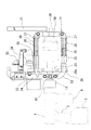
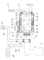
2 充電器
3 グリップ
4 オイルタンク
5 シリンダーシャフト
6 先端部
11 アタッチメント連結具
12 調整ピース
13 外装筒
14 補助シリンダー
15 補助シャフト
21 フレーム
22 枠材
23 プッシャー
24、24a ガイドアーム
25 鞘管
26 芯杆
27 ストッパー
28 リターンスプリング
29 ロードセル
30 端板
31 ハンドル
32 取付アーム
33 センサ本体
34 移動ヘッド
36 センサ本体
37 ロッド
38 センサブラケット
39、40 連結部
41 ロッド駆動アーム
43 第1スイッチ
44 補助アーム
45 補助グリップ
45a 第2スイッチ
46 表示盤
50 軸受部
51 ブシュ
Claims (7)
- 駆動機構を備えた装置本体と前記装置本体のアタッチメント取付部に取り付けられるアタッチメントとから成るハンドヘルド型圧入装置であって、
前記装置本体は、その下面に充電器を有するグリップとオイルタンクとを備え、その内部に駆動モータと、前記駆動モータによって駆動される油圧ポンプと、前記油圧ポンプによって進退駆動されるシリンダーシャフトが装備されて成り、
前記アタッチメントは、前記シリンダーシャフトに固定されるプッシャーと、前記プッシャーの上面及び下面に設けられるガイドアームを摺動させ得る間隔を保持して対設される一対の枠材から成るフレームとを備え、前記フレームの空間部内に部品圧入対象部を挿入した状態で前記プッシャーが前進することにより前記部品圧入対象部への部品圧入が行われることを特徴とする圧入装置。 - 前記アタッチメント取付部は、前記シリンダーシャフトのストローク調整ピースを介して前記本体に設置される、請求項1に記載の圧入装置。
- 前記ストローク調整ピースは、前記本体の先端部と前記アタッチメント取付部との間にネジ付けられる外装筒と、前記外装筒内に嵌装される補助シリンダーと、前記補助シリンダー内に摺動可能に配設されて、前記シリンダーシャフトに連結される補助シャフトとから成る、請求項1乃至3のいずれかに記載の圧入装置。
- 前記ガイドアームは水平方向に伸びる鞘管を有し、前記鞘管に、前記フレームの前端面側から前記鞘管に向かって水平方向に伸びて、一半部にリターンスプリングが巻装された芯杆の、前記リターンスプリングが巻装されていない他半部が挿入され、前記ガイドアームは前記鞘管を介して前記リターンスプリングによって常時復帰方向に付勢される、請求項1乃至3のいずれかに記載の圧入装置。
- 前記フレームに、前記プッシャーの移動量測定のためのセンサ機構が設置された、請求項1乃至4のいずれかに記載の圧入装置。
- 前記フレームの前端側内端面に、ロードセルが設置された、請求項1乃至5のいずれかに記載の圧入装置。
- 圧入作業時に握持するハンドルを備えた、請求項1乃至6のいずれかに記載の圧入装置。
Priority Applications (1)
| Application Number | Priority Date | Filing Date | Title |
|---|---|---|---|
| JP2016044343A JP6261635B2 (ja) | 2016-03-08 | 2016-03-08 | 圧入装置 |
Applications Claiming Priority (1)
| Application Number | Priority Date | Filing Date | Title |
|---|---|---|---|
| JP2016044343A JP6261635B2 (ja) | 2016-03-08 | 2016-03-08 | 圧入装置 |
Publications (2)
| Publication Number | Publication Date |
|---|---|
| JP2017159385A true JP2017159385A (ja) | 2017-09-14 |
| JP6261635B2 JP6261635B2 (ja) | 2018-01-17 |
Family
ID=59852971
Family Applications (1)
| Application Number | Title | Priority Date | Filing Date |
|---|---|---|---|
| JP2016044343A Active JP6261635B2 (ja) | 2016-03-08 | 2016-03-08 | 圧入装置 |
Country Status (1)
| Country | Link |
|---|---|
| JP (1) | JP6261635B2 (ja) |
Cited By (2)
| Publication number | Priority date | Publication date | Assignee | Title |
|---|---|---|---|---|
| CN110153678A (zh) * | 2019-05-29 | 2019-08-23 | 重庆市机电设计研究院 | 数控压力机 |
| CN116945103A (zh) * | 2023-09-20 | 2023-10-27 | 常州金土木工程仪器有限公司 | 一种传感器内芯衬套压配工装 |
Citations (4)
| Publication number | Priority date | Publication date | Assignee | Title |
|---|---|---|---|---|
| JPS6357074U (ja) * | 1986-10-03 | 1988-04-16 | ||
| JPH0570871U (ja) * | 1992-02-28 | 1993-09-24 | 寿一 小林 | パイプ用詰め栓打込み装置 |
| JPH0674272U (ja) * | 1993-03-31 | 1994-10-21 | 日産車体株式会社 | 圧入物交換器 |
| JPH0811065A (ja) * | 1994-06-28 | 1996-01-16 | Kandenko Co Ltd | 充電式油圧工具のオイルタンク構造 |
-
2016
- 2016-03-08 JP JP2016044343A patent/JP6261635B2/ja active Active
Patent Citations (4)
| Publication number | Priority date | Publication date | Assignee | Title |
|---|---|---|---|---|
| JPS6357074U (ja) * | 1986-10-03 | 1988-04-16 | ||
| JPH0570871U (ja) * | 1992-02-28 | 1993-09-24 | 寿一 小林 | パイプ用詰め栓打込み装置 |
| JPH0674272U (ja) * | 1993-03-31 | 1994-10-21 | 日産車体株式会社 | 圧入物交換器 |
| JPH0811065A (ja) * | 1994-06-28 | 1996-01-16 | Kandenko Co Ltd | 充電式油圧工具のオイルタンク構造 |
Cited By (3)
| Publication number | Priority date | Publication date | Assignee | Title |
|---|---|---|---|---|
| CN110153678A (zh) * | 2019-05-29 | 2019-08-23 | 重庆市机电设计研究院 | 数控压力机 |
| CN116945103A (zh) * | 2023-09-20 | 2023-10-27 | 常州金土木工程仪器有限公司 | 一种传感器内芯衬套压配工装 |
| CN116945103B (zh) * | 2023-09-20 | 2023-11-21 | 常州金土木工程仪器有限公司 | 一种传感器内芯衬套压配工装 |
Also Published As
| Publication number | Publication date |
|---|---|
| JP6261635B2 (ja) | 2018-01-17 |
Similar Documents
| Publication | Publication Date | Title |
|---|---|---|
| JP2008194801A5 (ja) | ||
| KR102315757B1 (ko) | 와이어 송급 기구 | |
| JP6261635B2 (ja) | 圧入装置 | |
| TW200628243A (en) | Bending machine with a controlled-return bending die | |
| JP2014205151A5 (ja) | ||
| WO2006002584A1 (fr) | Tete de machine a souder equipee d'un capteur de pression | |
| JP5717811B2 (ja) | ネジ締付装置を含むロボットシステム | |
| CN102699839B (zh) | 快速开合台钳及快速滑移和咬合部件 | |
| KR101183082B1 (ko) | 금속봉 가공 장치 | |
| EP1690625A4 (en) | CAP TIP REMOVAL MACHINE OF A WELDING MACHINE | |
| CA2970496C (en) | Apparatus and method for impact forming a cotter pin | |
| CN103707224A (zh) | 一种用于装配内孔衬套的夹具 | |
| CN210231632U (zh) | 一种辅助支架及手电钻 | |
| US8141859B2 (en) | Apparatus and method for effecting pin-to-shoulder tool separation for a friction stir welding pin tool | |
| JP6212309B2 (ja) | トグルクランプ | |
| CN103707264B (zh) | 一种射钉枪打钉深度调控装置 | |
| CN204183408U (zh) | 用于管材倒角的双工位夹紧装置 | |
| CN202964547U (zh) | 具有手动功能的销钉定位装置 | |
| CN204640015U (zh) | 双导杆气缸手动伸出机构 | |
| RU133768U1 (ru) | Съемник для выпрессовки втулок резцедержателей горных машин | |
| CN211464493U (zh) | 金属管无屑开料机的拉断装置 | |
| JP2010142847A (ja) | エコライズ装置を備えたc型溶接ガン | |
| CN203330955U (zh) | 一种用于汽车零件的定位装配装置 | |
| CN103101056A (zh) | 一种夹爪机构 | |
| CN104384905A (zh) | 一种可显示压入力值的压装设备 |
Legal Events
| Date | Code | Title | Description |
|---|---|---|---|
| A871 | Explanation of circumstances concerning accelerated examination |
Free format text: JAPANESE INTERMEDIATE CODE: A871 Effective date: 20170921 |
|
| A975 | Report on accelerated examination |
Free format text: JAPANESE INTERMEDIATE CODE: A971005 Effective date: 20171030 |
|
| A131 | Notification of reasons for refusal |
Free format text: JAPANESE INTERMEDIATE CODE: A131 Effective date: 20171117 |
|
| A521 | Request for written amendment filed |
Free format text: JAPANESE INTERMEDIATE CODE: A523 Effective date: 20171124 |
|
| TRDD | Decision of grant or rejection written | ||
| A01 | Written decision to grant a patent or to grant a registration (utility model) |
Free format text: JAPANESE INTERMEDIATE CODE: A01 Effective date: 20171204 |
|
| A61 | First payment of annual fees (during grant procedure) |
Free format text: JAPANESE INTERMEDIATE CODE: A61 Effective date: 20171212 |
|
| R150 | Certificate of patent or registration of utility model |
Ref document number: 6261635 Country of ref document: JP Free format text: JAPANESE INTERMEDIATE CODE: R150 |
|
| R250 | Receipt of annual fees |
Free format text: JAPANESE INTERMEDIATE CODE: R250 |
|
| R250 | Receipt of annual fees |
Free format text: JAPANESE INTERMEDIATE CODE: R250 |
|
| R250 | Receipt of annual fees |
Free format text: JAPANESE INTERMEDIATE CODE: R250 |
|
| R250 | Receipt of annual fees |
Free format text: JAPANESE INTERMEDIATE CODE: R250 |