JP2017159385A - Press-in device - Google Patents
Press-in device Download PDFInfo
- Publication number
- JP2017159385A JP2017159385A JP2016044343A JP2016044343A JP2017159385A JP 2017159385 A JP2017159385 A JP 2017159385A JP 2016044343 A JP2016044343 A JP 2016044343A JP 2016044343 A JP2016044343 A JP 2016044343A JP 2017159385 A JP2017159385 A JP 2017159385A
- Authority
- JP
- Japan
- Prior art keywords
- press
- fitting
- frame
- pusher
- fitting device
- Prior art date
- Legal status (The legal status is an assumption and is not a legal conclusion. Google has not performed a legal analysis and makes no representation as to the accuracy of the status listed.)
- Granted
Links
- 239000000463 material Substances 0.000 abstract description 2
- 238000002347 injection Methods 0.000 description 5
- 239000007924 injection Substances 0.000 description 5
- 238000001514 detection method Methods 0.000 description 2
- 210000003813 thumb Anatomy 0.000 description 2
- 238000011000 absolute method Methods 0.000 description 1
- 230000006835 compression Effects 0.000 description 1
- 238000007906 compression Methods 0.000 description 1
- 238000005259 measurement Methods 0.000 description 1
- 238000000034 method Methods 0.000 description 1
- 239000000725 suspension Substances 0.000 description 1
Images


Landscapes
- Automatic Assembly (AREA)
- Hand Tools For Fitting Together And Separating, Or Other Hand Tools (AREA)
Abstract
Description
本発明は、圧入装置に関するものであり、より詳細には、例えば、各種機械器具における軸孔やボスへのブシュ圧入作業等の部品圧入作業に用いる簡易な構成のハンドヘルド型圧入装置に関するものである。 The present invention relates to a press-fitting device, and more particularly, to a hand-held press-fitting device with a simple configuration used for parts press-fitting work such as bush press-fitting work to shaft holes and bosses in various machine tools. .
軸を備える各種機械器具、機械部品等においては、その軸孔内に軸を低摩擦支持するブシュが圧入される。通例、このブシュの圧入にはトン単位の圧入力が必要となるため、その圧入作業は容易ではない。 In various machine tools, machine parts, and the like including a shaft, a bush for supporting the shaft with low friction is press-fitted into the shaft hole. Usually, the press-fitting work is not easy because the press-fitting of this bush requires press-fitting in tons.
従来、このブシュの圧入作業を機械的に行うための種々のブシュ圧入装置が提唱されている(特開2005−324635号公報、特開2005−238397号公報、特開2001−62645号公報等)。しかし、従来提唱されているこれらのブシュ圧入装置は、いずれも大掛かりな構成で導入にコストがかかるものであり、手軽に利用し得るものではない。 Conventionally, various bush press-fitting devices for mechanically performing the bush press-fitting work have been proposed (Japanese Patent Laid-Open Nos. 2005-324635, 2005-23897, 2001-62645, etc.). . However, these bush press-fitting devices that have been proposed in the past are both large-scale and costly to introduce, and cannot be used easily.
上述したように、従来提唱されているブシュ圧入装置は、いずれも大掛かりな構成で導入にコストがかかり、手軽に利用し得るものではなかった。そこで本発明は、シンプル且つコンパクトな構成で比較的低コストにて供給でき、使い勝手がよく、トン単位の圧入力が必要なブシュの圧入作業等に用いるのに好適なハンドヘルド型圧入装置を提供することを課題とする。 As described above, all of the bush press-fitting devices that have been proposed in the past have a large-scale configuration and are expensive to introduce and cannot be easily used. Therefore, the present invention provides a hand-held press-fitting device that can be supplied at a relatively low cost with a simple and compact configuration, is easy to use, and is suitable for use in press-fitting a bush that requires press-fitting in tons. This is the issue.
上記課題を解決するための請求項1に記載の発明は、駆動機構を備えた装置本体と前記装置本体のアタッチメント取付部に取り付けられるアタッチメントとから成るハンドヘルド型圧入装置であって、前記装置本体は、その下面に充電器を有するグリップとオイルタンクとを備え、その内部に駆動モータと、前記駆動モータによって駆動される油圧ポンプと、前記油圧ポンプによって進退駆動されるシリンダーシャフトが装備されて成り、前記アタッチメントは、前記シリンダーシャフトに固定されるプッシャーと、前記プッシャーの上面及び下面に設けられるガイドアームを摺動させ得る間隔を保持して対設される一対の枠材から成るフレームとを備え、前記フレームの空間部内に部品圧入対象部を挿入した状態で前記プッシャーが前進することにより前記部品圧入対象部への部品圧入が行われることを特徴とする圧入装置である。 The invention according to claim 1 for solving the above problem is a hand-held press-fitting device comprising a device main body provided with a drive mechanism and an attachment attached to an attachment mounting portion of the device main body, , Comprising a grip and an oil tank having a charger on its lower surface, equipped with a drive motor, a hydraulic pump driven by the drive motor, and a cylinder shaft driven forward and backward by the hydraulic pump, The attachment includes a pusher fixed to the cylinder shaft, and a frame made of a pair of frame members provided so as to be opposed to each other with a distance at which guide arms provided on the upper and lower surfaces of the pusher can slide. The pusher moves forward with the part press-fitting target part inserted into the space of the frame. A press-fitting apparatus characterized by components pressed into the component press-object portion is carried out by.
一実施形態においては、前記アタッチメント取付部は、前記シリンダーシャフトのストローク調整ピースを介して前記本体に設置される。例えば、前記ストローク調整ピースは、前記本体の先端部と前記アタッチメント取付部との間にネジ付けられる外装筒と、前記外装筒内に嵌装される補助シリンダーと、前記補助シリンダー内に摺動可能に配設されて、前記シリンダーシャフトに連結される補助シャフトとで構成される。 In one embodiment, the attachment mounting portion is installed on the main body via a stroke adjusting piece of the cylinder shaft. For example, the stroke adjusting piece is slidable in an outer cylinder that is screwed between the tip of the main body and the attachment mounting portion, an auxiliary cylinder that is fitted in the outer cylinder, and the auxiliary cylinder. And an auxiliary shaft connected to the cylinder shaft.
一実施形態においては、前記ガイドアームは水平方向に伸びる鞘管を有し、前記鞘管に、前記フレームの前端面側から水平方向に伸びて一半部にリターンスプリングが巻装された芯杆の、前記リターンスプリングが巻装されていない他半部が挿入され、前記ガイドアームは前記鞘管を介して前記リターンスプリングによって常時復帰方向に付勢される。 In one embodiment, the guide arm has a sheath tube that extends in the horizontal direction, and the sheath tube extends in the horizontal direction from the front end surface side of the frame and has a return spring wound around one half thereof. The other half portion around which the return spring is not wound is inserted, and the guide arm is always urged in the return direction by the return spring through the sheath tube.
一実施形態においては、前記フレームに、前記プッシャーの移動量測定のためのセンサ機構が設置され、また、前記フレームの前端側内端面にロードセルが設置される。更に一実施形態においては、前記フレームに、圧入作業時に握持するハンドルが設置される。 In one embodiment, a sensor mechanism for measuring the amount of movement of the pusher is installed in the frame, and a load cell is installed on the front end side inner end surface of the frame. In one embodiment, the frame is provided with a handle for gripping during press-fitting work.
本発明は上述したとおりであって、シンプル且つコンパクトな構成であって、比較的低コストにて供給でき、使い勝手がよく、トン単位の圧入力が必要なブシュの圧入作業等に用いるのに好適なハンドヘルド型圧入装置を提供し得る効果がある。 The present invention is as described above, has a simple and compact configuration, can be supplied at a relatively low cost, is easy to use, and is suitable for use in press-fitting work of a bush that requires pressure input in tons. This can provide a simple handheld press-fitting device.
本発明を実施するための形態につき、添付図面を参照しつつ説明する。先ず、図1乃至図5に示される実施形態について説明する。本発明に係る圧入装置は、ガンタイプのハンドヘルド型圧入装置であって、その装置本体1の下面には、下端部に充電器2を備えたグリップ3と、オイルタンク4が設置される。図示してないが、装置本体1内には駆動モータと、該駆動モータによって駆動される油圧ポンプと、油圧ポンプによって進退駆動されるピストンが装備され、ピストンに連結されたシリンダーシャフト5が進退動作する。なお、装置本体1内の構成は一般的なものであるので、詳細な説明は省略する。
DESCRIPTION OF EMBODIMENTS Embodiments for carrying out the present invention will be described with reference to the accompanying drawings. First, the embodiment shown in FIGS. 1 to 5 will be described. The press-fitting device according to the present invention is a gun-type hand-held press-fitting device, and a
装置本体1の先端部6にはネジが切られ、そこにアタッチメント連結具11がねじ付け固定されるが、この構成では、シリンダーシャフト5のストロークが、本発明において企図するストロ−クに足りない場合が少なくない。そこで、本発明においては、装置本体1の先端部6とアタッチメント連結具11との間に、シリンダーシャフト5のストロークを伸長させるための調整ピース12を介在させることとする。即ち、装置本体1の先端部6からアタッチメント連結具11を外し、そこに調整ピース12の一端部をネジ付け、調整ピース12の他端部にアタッチメント連結具11をネジ付ける(図3参照)。
The
調整ピース12は、外装筒13と、その内側に嵌装される補助シリンダー14と、補助シリンダー14内に摺動自在に配設される補助シャフト15とで構成される。外装筒13は、後端部に装置本体1の先端部6をネジ込むためのメネジ部13aを備え、前端部にアタッチメント連結具11をネジ付けるためのオネジ部13bを備える。また、補助シャフト15は、後端部にシリンダーシャフト5の先端部をネジ込むためのメネジ部を備え、アタッチメント連結具11から伸び出るその先端部に、後述するプッシャー21をネジ付け固定するためのオネジ部15aを備える。
The
シリンダーシャフト5のストロークの所望伸長長さに対応し得るように、調整ピース12として長さの異なる複数種のものを用意して、選択交換可能にしてもよい。
A plurality of kinds of
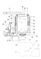
アタッチメント連結具11には、一対の枠材22を適宜間隔を置いて対設して成るフレーム21が固定される。通例、フレーム21の枠材22は中抜きの四角形状に形成されるが、そのサイズは、ブシュ51の圧入作業時においてその内側空間部に、種々の機器のブシュ51の圧入対象となる軸受部52を挿入するのに十分な大きさとされる(図4参照)。フレーム21の端板30の内側面にロードセル29が定着され、プッシャー23による圧縮荷重が検出される。
A
フレーム21内に臨む補助シャフト15の先端オネジ部15aにプッシャー23がネジ付け固定され、プッシャー23は補助シャフト15に駆動されてフレーム21の空間部内を進退動作する。プッシャー23の上面及び下面には、それぞれフレーム21の枠材22間を摺動するガイドアーム24、24aが設置される。
A
各ガイドアーム24、24aには、1本又は複数本の鞘管25が水平方向に突設され、各鞘管25内に芯杆26の前半部が挿通される。芯杆26は、枠材22の先端部間に設置されたストッパー27から鞘管25に向かって水平方向に伸び、その先端部は鞘管25を通り抜け、更に、ガイドアーム24、24aを突き抜ける位置まで伸びる。芯杆26の後半部には、リターンスプリング28が巻装される。リターンスプリング28は、その一端がストッパー27に当接して押え止められ、他端が鞘管25の端面に当接して押え止められることで、常時、鞘管25を押圧付勢するよう作用する。
Each
フレーム21には更に、圧入作業時に握持するハンドル31と、ガイドアーム24、24aの移動量、換言すれば、プッシャー23の移動量を検出するためのセンサ機構が設置される。ハンドル31は、フレーム21の端板30に取り付けられる。センサ機構は、各枠材22から上方に伸びるセンサ取付アーム32に設置されるセンサ本体33と、上側のガイドアーム24に設置される移動ヘッド34とから成る。移動ヘッド34はプッシャー23と一体に移動し、センサ本体33によってプッシャー23の移動距離が検出される。
The
そして、このプッシャー23の移動距離と、ロードセル29によって検出される当該移動距離に対応するプッシャー23の圧縮荷重とがトレースされることで、適正な押圧力を得るためのプッシャー23の移動量が取得され、それに基づいて、装置本体1内の駆動モータが制御される。
Then, the movement distance of the
上記構成の圧入装置を用いてブシュ51を軸受部50に圧入する作業を行うに当たっては、治具をセットしたブシュ51を軸受部50に仮嵌めし、装置本体1のグリップ3及びハンドル31を握持して、軸受部50をフレーム21内に進入させる(図4参照)。そこで、グリップ3に配備されているトリガー3aを引いて装置本体1内のモーターを始動すると、油圧ポンプ等が作動し、治具に当接しているプッシャー23が、シリンダーシャフト5及び補助シャフト15を介し、リターンスプリング28の付勢力に抗して前進し、フレーム21の端板30との間に軸受部50を挟み込んで強圧する。かくして、軸受部50に仮嵌めされているブシュ51が、軸受部50内に完全に圧入される。
In performing the work of press-fitting the
圧入作業終了後、トリガー3aを離して装置本体1内のモーターを停止させると、プッシャー23による軸受部50に対する押圧作用が解除されるに伴い、リターンスプリング28による付勢力がガイドアーム24,24aを介してプッシャー23に伝わることで、プッシャー23は元の位置に戻る。
When the trigger 3a is released after the press-fitting operation is finished and the motor in the apparatus main body 1 is stopped, the urging force of the
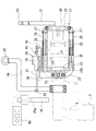
次いで、図5及び図6に示される第2の実施形態について説明する。この第2の実施形態は、上記第1の実施形態の構成に対し、主に、センサ機構の構成とスイッチ部分の構成を変更したものである。なお、第1の実施形態におけると同じ符号を付した部分は同じ構成部分を示しているので、詳細な説明は省略する。 Next, a second embodiment shown in FIGS. 5 and 6 will be described. In the second embodiment, the configuration of the sensor mechanism and the configuration of the switch portion are mainly changed from the configuration of the first embodiment. In addition, since the part which attached | subjected the same code | symbol as 1st Embodiment has shown the same component, detailed description is abbreviate | omitted.
第2の実施形態においては、直線型アブソリュート方式(0を基準にして、そこからの距離を表わす絶対番地方式)のエンコーダである位置検出センサ35が用いられる。図示した位置検出センサ35は、センサ本体36に2本のロッド37が摺動自在に挿通されたツインロッド方式のものであって、センサ本体36は、一対の枠材22の端部を跨ぐようにして枠材22に固定されるセンサブラケット38上に固定設置される。2本のロッド37の端部は連結部材39、40によって連結され、一方の連結部材40に、ガイドアーム24の上端から伸びるL字形のロッド駆動アーム41の先端部が固定される。
In the second embodiment, a
このセンサ機構の場合は、プッシャー23が進退動作すると、その動きに追随してガイドアーム24及びロッド駆動アーム41を介し、連結部材40に連結されている一対のロッド37が一体に進退動作する。その際センサ本体36は、センサブラケット38により固定支持されていて移動しないので、ロッド37がセンサ本体36内を摺動することになる。かくして、センサ本体36内においてロッド移動量、換言すれば、プッシャー23の移動量が検出され、第1の実施形態と同様に、そのプッシャー23の移動距離と共に、その移動距離に対応するプッシャー23の圧縮荷重が、ロードセル29によって検出される。
In the case of this sensor mechanism, when the
また、第2の実施形態においては、プッシャー23駆動のオン・オフ操作をするための第1スイッチ43が、ハンドル31の先端部に配備される。また、装置本体1の調整ピース12付近に上方に伸びる補助アーム44が設置され、それに、補助グリップ45と、オン・オフ表示ランプ、計測値表示窓等を備えた表示盤46とが取り付けられる。そして、補助グリップ45に第2スイッチ45aが配備される。なお、本装置はハンドヘルド型ではあるが、重量のあるものであるので、それを支持させて作業の円滑化を図るために、補助アーム44の先端部に吊下用リング47を配設し、そこに、作業場に掛け渡したワイヤー等を通すようにする。
In the second embodiment, a
この構成の場合は、操作時に一方の手でハンドル31を握持し、他方の手で補助グリップ45を握持することになるが、その場合、ハンドル31を握持した状態のまま、親指で第1スイッチ43を操作することが可能となり、また、補助グリップ45を握持した状態のまま、親指で第2スイッチ45aを操作することが可能となるので、操作性がよい。この場合、第1スイッチ43と第2スイッチ45aとをダブルスイッチにし、双方が押されない限り動作しないようにして、安全性を図るようにすることが好ましい。
In this configuration, the
本発明に係る圧入装置は、上記ブシュの圧入作業に好適なものであるが、これに限らず、他の種々の部品の圧入や、部位の強圧作業に用いることができることは言うまでもない。 The press-fitting device according to the present invention is suitable for the press-fitting work of the bush. However, the present invention is not limited to this, and it is needless to say that the press-fitting apparatus can be used for press-fitting other various parts and the strong press work of the part.
1 装置本体
2 充電器
3 グリップ
4 オイルタンク
5 シリンダーシャフト
6 先端部
11 アタッチメント連結具
12 調整ピース
13 外装筒
14 補助シリンダー
15 補助シャフト
21 フレーム
22 枠材
23 プッシャー
24、24a ガイドアーム
25 鞘管
26 芯杆
27 ストッパー
28 リターンスプリング
29 ロードセル
30 端板
31 ハンドル
32 取付アーム
33 センサ本体
34 移動ヘッド
36 センサ本体
37 ロッド
38 センサブラケット
39、40 連結部
41 ロッド駆動アーム
43 第1スイッチ
44 補助アーム
45 補助グリップ
45a 第2スイッチ
46 表示盤
50 軸受部
51 ブシュ
DESCRIPTION OF SYMBOLS 1 Apparatus
Claims (7)
前記装置本体は、その下面に充電器を有するグリップとオイルタンクとを備え、その内部に駆動モータと、前記駆動モータによって駆動される油圧ポンプと、前記油圧ポンプによって進退駆動されるシリンダーシャフトが装備されて成り、
前記アタッチメントは、前記シリンダーシャフトに固定されるプッシャーと、前記プッシャーの上面及び下面に設けられるガイドアームを摺動させ得る間隔を保持して対設される一対の枠材から成るフレームとを備え、前記フレームの空間部内に部品圧入対象部を挿入した状態で前記プッシャーが前進することにより前記部品圧入対象部への部品圧入が行われることを特徴とする圧入装置。 A handheld press-fitting device comprising a device main body provided with a drive mechanism and an attachment attached to an attachment mounting portion of the device main body,
The apparatus body includes a grip and an oil tank having a charger on its lower surface, and is equipped with a drive motor, a hydraulic pump driven by the drive motor, and a cylinder shaft driven forward and backward by the hydraulic pump. Made up of,
The attachment includes a pusher fixed to the cylinder shaft, and a frame made of a pair of frame members provided so as to be opposed to each other with a distance at which guide arms provided on the upper and lower surfaces of the pusher can slide. The press-fitting device, wherein the part press-fitting to the part press-fitting target part is performed by the pusher moving forward in a state where the part press-fitting target part is inserted into the space part of the frame.
Priority Applications (1)
| Application Number | Priority Date | Filing Date | Title |
|---|---|---|---|
| JP2016044343A JP6261635B2 (en) | 2016-03-08 | 2016-03-08 | Press-fitting device |
Applications Claiming Priority (1)
| Application Number | Priority Date | Filing Date | Title |
|---|---|---|---|
| JP2016044343A JP6261635B2 (en) | 2016-03-08 | 2016-03-08 | Press-fitting device |
Publications (2)
| Publication Number | Publication Date |
|---|---|
| JP2017159385A true JP2017159385A (en) | 2017-09-14 |
| JP6261635B2 JP6261635B2 (en) | 2018-01-17 |
Family
ID=59852971
Family Applications (1)
| Application Number | Title | Priority Date | Filing Date |
|---|---|---|---|
| JP2016044343A Active JP6261635B2 (en) | 2016-03-08 | 2016-03-08 | Press-fitting device |
Country Status (1)
| Country | Link |
|---|---|
| JP (1) | JP6261635B2 (en) |
Cited By (3)
| Publication number | Priority date | Publication date | Assignee | Title |
|---|---|---|---|---|
| CN110153678A (en) * | 2019-05-29 | 2019-08-23 | 重庆市机电设计研究院 | CNC press |
| CN110216445A (en) * | 2019-05-30 | 2019-09-10 | 北京航天斯达科技有限公司 | A kind of oil pipe compression bonding apparatus and compression bonding method |
| CN116945103A (en) * | 2023-09-20 | 2023-10-27 | 常州金土木工程仪器有限公司 | Press-fit tool for sensor inner core bushing |
Citations (4)
| Publication number | Priority date | Publication date | Assignee | Title |
|---|---|---|---|---|
| JPS6357074U (en) * | 1986-10-03 | 1988-04-16 | ||
| JPH0570871U (en) * | 1992-02-28 | 1993-09-24 | 寿一 小林 | Filling device for pipes |
| JPH0674272U (en) * | 1993-03-31 | 1994-10-21 | 日産車体株式会社 | Press fit matter exchanger |
| JPH0811065A (en) * | 1994-06-28 | 1996-01-16 | Kandenko Co Ltd | Oil tank structure for charging type hydraulic tool |
-
2016
- 2016-03-08 JP JP2016044343A patent/JP6261635B2/en active Active
Patent Citations (4)
| Publication number | Priority date | Publication date | Assignee | Title |
|---|---|---|---|---|
| JPS6357074U (en) * | 1986-10-03 | 1988-04-16 | ||
| JPH0570871U (en) * | 1992-02-28 | 1993-09-24 | 寿一 小林 | Filling device for pipes |
| JPH0674272U (en) * | 1993-03-31 | 1994-10-21 | 日産車体株式会社 | Press fit matter exchanger |
| JPH0811065A (en) * | 1994-06-28 | 1996-01-16 | Kandenko Co Ltd | Oil tank structure for charging type hydraulic tool |
Cited By (4)
| Publication number | Priority date | Publication date | Assignee | Title |
|---|---|---|---|---|
| CN110153678A (en) * | 2019-05-29 | 2019-08-23 | 重庆市机电设计研究院 | CNC press |
| CN110216445A (en) * | 2019-05-30 | 2019-09-10 | 北京航天斯达科技有限公司 | A kind of oil pipe compression bonding apparatus and compression bonding method |
| CN116945103A (en) * | 2023-09-20 | 2023-10-27 | 常州金土木工程仪器有限公司 | Press-fit tool for sensor inner core bushing |
| CN116945103B (en) * | 2023-09-20 | 2023-11-21 | 常州金土木工程仪器有限公司 | Press-fit tool for sensor inner core bushing |
Also Published As
| Publication number | Publication date |
|---|---|
| JP6261635B2 (en) | 2018-01-17 |
Similar Documents
| Publication | Publication Date | Title |
|---|---|---|
| JP2008194801A5 (en) | ||
| JP6261635B2 (en) | Press-fitting device | |
| CN107649813A (en) | A kind of spring catch stopping means | |
| KR102315757B1 (en) | Wire-advancing mechanism | |
| TW200628243A (en) | Bending machine with a controlled-return bending die | |
| JP2014205151A5 (en) | ||
| JP2015036180A (en) | Screw tightening device | |
| CN102699839B (en) | Quickly opened and closed bench clamp and quick sliding and engaging part | |
| EP1690625A4 (en) | Cap tip removing device of welding machine | |
| CN103707224A (en) | Clamp for assembling inner bore bush | |
| CA2970496C (en) | Apparatus and method for impact forming a cotter pin | |
| CN201023217Y (en) | A manual hydraulic booster vise | |
| CN210967742U (en) | Axle sleeve snatchs integrative mechanism of impressing | |
| CN210231632U (en) | Auxiliary support and electric hand drill | |
| US8141859B2 (en) | Apparatus and method for effecting pin-to-shoulder tool separation for a friction stir welding pin tool | |
| CN204127087U (en) | Optical axis clamp device | |
| JP6212309B2 (en) | Toggle Clamps | |
| CN104384905A (en) | Press fitting equipment capable of displaying press-in force value | |
| CN103707264B (en) | Nailing depth regulating device of nail gun | |
| CN204183408U (en) | For the double clamping device of tubing chamfering | |
| CN202964547U (en) | Dowel positioning device with manual function | |
| CN204640015U (en) | Two guide rod cylinder manually stretches out mechanism | |
| CN211464493U (en) | Stretch-breaking device of chipless metal pipe cutting machine | |
| JP2015049211A (en) | Gripper and material testing machine | |
| JP2010142847A (en) | C type welding gun equipped with equalizer |
Legal Events
| Date | Code | Title | Description |
|---|---|---|---|
| A871 | Explanation of circumstances concerning accelerated examination |
Free format text: JAPANESE INTERMEDIATE CODE: A871 Effective date: 20170921 |
|
| A975 | Report on accelerated examination |
Free format text: JAPANESE INTERMEDIATE CODE: A971005 Effective date: 20171030 |
|
| A131 | Notification of reasons for refusal |
Free format text: JAPANESE INTERMEDIATE CODE: A131 Effective date: 20171117 |
|
| A521 | Request for written amendment filed |
Free format text: JAPANESE INTERMEDIATE CODE: A523 Effective date: 20171124 |
|
| TRDD | Decision of grant or rejection written | ||
| A01 | Written decision to grant a patent or to grant a registration (utility model) |
Free format text: JAPANESE INTERMEDIATE CODE: A01 Effective date: 20171204 |
|
| A61 | First payment of annual fees (during grant procedure) |
Free format text: JAPANESE INTERMEDIATE CODE: A61 Effective date: 20171212 |
|
| R150 | Certificate of patent or registration of utility model |
Ref document number: 6261635 Country of ref document: JP Free format text: JAPANESE INTERMEDIATE CODE: R150 |
|
| R250 | Receipt of annual fees |
Free format text: JAPANESE INTERMEDIATE CODE: R250 |
|
| R250 | Receipt of annual fees |
Free format text: JAPANESE INTERMEDIATE CODE: R250 |
|
| R250 | Receipt of annual fees |
Free format text: JAPANESE INTERMEDIATE CODE: R250 |
|
| R250 | Receipt of annual fees |
Free format text: JAPANESE INTERMEDIATE CODE: R250 |
|
| R250 | Receipt of annual fees |
Free format text: JAPANESE INTERMEDIATE CODE: R250 |