JP2014532973A - 防水及び防塵形のイルミネーションスイッチ要素 - Google Patents
防水及び防塵形のイルミネーションスイッチ要素 Download PDFInfo
- Publication number
- JP2014532973A JP2014532973A JP2014540314A JP2014540314A JP2014532973A JP 2014532973 A JP2014532973 A JP 2014532973A JP 2014540314 A JP2014540314 A JP 2014540314A JP 2014540314 A JP2014540314 A JP 2014540314A JP 2014532973 A JP2014532973 A JP 2014532973A
- Authority
- JP
- Japan
- Prior art keywords
- switch element
- case
- switch
- cap
- element according
- Prior art date
- Legal status (The legal status is an assumption and is not a legal conclusion. Google has not performed a legal analysis and makes no representation as to the accuracy of the status listed.)
- Ceased
Links
Images


Classifications
-
- H—ELECTRICITY
- H01—ELECTRIC ELEMENTS
- H01H—ELECTRIC SWITCHES; RELAYS; SELECTORS; EMERGENCY PROTECTIVE DEVICES
- H01H13/00—Switches having rectilinearly-movable operating part or parts adapted for pushing or pulling in one direction only, e.g. push-button switch
- H01H13/02—Details
- H01H13/04—Cases; Covers
- H01H13/06—Dustproof, splashproof, drip-proof, waterproof or flameproof casings
-
- H—ELECTRICITY
- H01—ELECTRIC ELEMENTS
- H01H—ELECTRIC SWITCHES; RELAYS; SELECTORS; EMERGENCY PROTECTIVE DEVICES
- H01H9/00—Details of switching devices, not covered by groups H01H1/00 - H01H7/00
- H01H9/02—Bases, casings, or covers
- H01H9/04—Dustproof, splashproof, drip-proof, waterproof, or flameproof casings
- H01H9/047—Dustproof, splashproof, drip-proof, waterproof, or flameproof casings provided with venting means
-
- H—ELECTRICITY
- H01—ELECTRIC ELEMENTS
- H01H—ELECTRIC SWITCHES; RELAYS; SELECTORS; EMERGENCY PROTECTIVE DEVICES
- H01H13/00—Switches having rectilinearly-movable operating part or parts adapted for pushing or pulling in one direction only, e.g. push-button switch
- H01H13/02—Details
- H01H13/023—Light-emitting indicators
-
- H—ELECTRICITY
- H01—ELECTRIC ELEMENTS
- H01H—ELECTRIC SWITCHES; RELAYS; SELECTORS; EMERGENCY PROTECTIVE DEVICES
- H01H13/00—Switches having rectilinearly-movable operating part or parts adapted for pushing or pulling in one direction only, e.g. push-button switch
- H01H13/02—Details
- H01H13/10—Bases; Stationary contacts mounted thereon
-
- H—ELECTRICITY
- H01—ELECTRIC ELEMENTS
- H01H—ELECTRIC SWITCHES; RELAYS; SELECTORS; EMERGENCY PROTECTIVE DEVICES
- H01H9/00—Details of switching devices, not covered by groups H01H1/00 - H01H7/00
- H01H9/02—Bases, casings, or covers
- H01H9/04—Dustproof, splashproof, drip-proof, waterproof, or flameproof casings
- H01H2009/048—Dustproof, splashproof, drip-proof, waterproof, or flameproof casings using a sealing boot, e.g. the casing having separate elastic body surrounding the operating member and hermetically closing the opening for it
-
- H—ELECTRICITY
- H01—ELECTRIC ELEMENTS
- H01H—ELECTRIC SWITCHES; RELAYS; SELECTORS; EMERGENCY PROTECTIVE DEVICES
- H01H13/00—Switches having rectilinearly-movable operating part or parts adapted for pushing or pulling in one direction only, e.g. push-button switch
- H01H13/02—Details
- H01H13/023—Light-emitting indicators
- H01H2013/026—Light-emitting indicators with two or more independent lighting elements located inside the push button switch that illuminate separate zones of push buttons
-
- H—ELECTRICITY
- H01—ELECTRIC ELEMENTS
- H01H—ELECTRIC SWITCHES; RELAYS; SELECTORS; EMERGENCY PROTECTIVE DEVICES
- H01H2213/00—Venting
- H01H2213/002—Venting with external pressure
- H01H2213/006—Labyrinth
-
- H—ELECTRICITY
- H01—ELECTRIC ELEMENTS
- H01H—ELECTRIC SWITCHES; RELAYS; SELECTORS; EMERGENCY PROTECTIVE DEVICES
- H01H2219/00—Legends
- H01H2219/036—Light emitting elements
- H01H2219/048—Constituting key
-
- H—ELECTRICITY
- H01—ELECTRIC ELEMENTS
- H01H—ELECTRIC SWITCHES; RELAYS; SELECTORS; EMERGENCY PROTECTIVE DEVICES
- H01H2221/00—Actuators
- H01H2221/024—Transmission element
- H01H2221/03—Stoppers for on or off position
-
- H—ELECTRICITY
- H01—ELECTRIC ELEMENTS
- H01H—ELECTRIC SWITCHES; RELAYS; SELECTORS; EMERGENCY PROTECTIVE DEVICES
- H01H2223/00—Casings
- H01H2223/002—Casings sealed
-
- H—ELECTRICITY
- H01—ELECTRIC ELEMENTS
- H01H—ELECTRIC SWITCHES; RELAYS; SELECTORS; EMERGENCY PROTECTIVE DEVICES
- H01H2223/00—Casings
- H01H2223/002—Casings sealed
- H01H2223/006—Purge gas
-
- H—ELECTRICITY
- H01—ELECTRIC ELEMENTS
- H01H—ELECTRIC SWITCHES; RELAYS; SELECTORS; EMERGENCY PROTECTIVE DEVICES
- H01H2223/00—Casings
- H01H2223/044—Protecting cover
-
- H—ELECTRICITY
- H01—ELECTRIC ELEMENTS
- H01H—ELECTRIC SWITCHES; RELAYS; SELECTORS; EMERGENCY PROTECTIVE DEVICES
- H01H2229/00—Manufacturing
- H01H2229/044—Injection moulding
- H01H2229/046—Multi-colour or double shot injection moulding
-
- H—ELECTRICITY
- H01—ELECTRIC ELEMENTS
- H01H—ELECTRIC SWITCHES; RELAYS; SELECTORS; EMERGENCY PROTECTIVE DEVICES
- H01H2239/00—Miscellaneous
- H01H2239/034—Environmental protection
Abstract
Description
2 キャップ
3 端部ストッパ
4 ガイド
5 シリコンマット
6 プリント基板
7 圧力調整要素
8 接触子
9 ケース
10 フレーム
11 取り付けベゼル
12 保護隔壁
13 通気路
14 プラグ用外殻
15 ケースのガイド溝
16 ガイドのガイド輪郭
17 操作方向にあるケース内の端部ストッパ
18 操作方向にあるガイド内の端部ストッパ
19 フレームに当接する係止要素
20 取り付けベゼルに当接する係止フック
21 探照灯
22 機能灯
23 操作面
24 ケースの縁部
25 フレームの密封輪郭
26 フレームの縁部
27 取り付けベゼルに対する密封輪郭
28 シリコンマットの復原ドーム構造体
Claims (18)
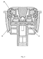
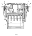
- 押しボタンスイッチの直線運動を切り替え用の電気信号に変換するための、ケースとこのケース内で2つの最終位置間の行程距離だけ軸方向に摺動可能なキャップとを有する、防水及び防塵形のイルミネーションスイッチ要素であって、前記キャップは、外側に対して密封する保護隔壁を有し、この保護隔壁は、複数要素射出成形法によってフレキシブルなプラスチック材料から構成されている当該スイッチ要素において、
前記スイッチ要素は、そのケース(9)の内部に、少なくとも4つの接触子(8)と、1つの圧力調整要素(7)と、1つのプリント基板(6)と、復原要素及び光仕切り要素としての1つのシリコンマット(5)と、1つのガイド(4)と、1つの端部ストッパ(3)と、成形された保護隔壁(12)を有する1つのキャップ(2)と、1つのフレーム(10)とを有し、前記少なくとも4つの接触子のうちの少なくとも2つの接触子が、同じ輪郭を成して形成されていて、当該4つの接触子(8)は、そのプラグ領域内での直線状の配置が、前記ケースの内部では当該4つの接触子を四角形の4つの角に設ける配置になるように屈曲されていて、少なくとも1つの押しボタンスイッチ及び少なくとも2つの照明器具が、前記プリント基板(6)上に配置されていることを特徴とするスイッチ要素。 - 前記スイッチ要素(1)の内部が、圧力調整要素(7)を介して通気路(13)を経由して前記スイッチ要素(1)の外気に通気されていることを特徴とする請求項1に記載のスイッチ要素。
- 前記通気路(13)は、蛇行状に形成されていることを特徴とする請求項2に記載のスイッチ要素。
- 前記フレーム(10)は、前記通気路(13)用の保護カバーを外側から形成することを特徴とする請求項3に記載のスイッチ要素。
- 前記ケース(9)は、プラグ用外殻(14)と一体的に形成されていることを特徴とする請求項1〜4のいずれか1項に記載のスイッチ要素。
- 少なくとも3つのガイド溝(15)が、前記ケース(9)の内部に配置されていて、これらのガイド溝(15)は、前記ガイド(4)のガイド輪郭(16)に一致することを特徴とする請求項1〜5のいずれか1項に記載のスイッチ要素。
- 前記ガイド輪郭(16)は、前記ケース(9)の内部のプラグ用外殻(14)から突出していることを特徴とする請求項1〜6のいずれか1項に記載のスイッチ要素。
- 前記圧力調整要素(7)と前記プリント基板(6)とのための収容領域が、前記ケース(9)の上方の開口部の近くに存在することを特徴とする請求項1〜7のいずれか1項に記載のスイッチ要素。
- 前記ガイド(4)は、少なくとも3つの端部ストッパ(18)を有し、これらの端部ストッパ(18)は、T字形の輪郭を成して前記ガイド輪郭(16)の上方に配置されていることを特徴とする請求項1〜8のいずれか1項に記載のスイッチ要素。
- 追加の工具なしに、前記スイッチ要素(1)の簡単な取り外しを可能にする輪郭が、前記取り付けベゼル(11)の係止フック(20)に形成されていることを特徴とする請求項1〜9のいずれか1項に記載のスイッチ要素。
- 前記フレーム(10)と前記取り付けベゼル(11)とが、それらの形状的に安定な輪郭によって当接して取り付けられていることを特徴とする請求項1〜10のいずれか1項に記載のスイッチ要素。
- フレキシブルなプラスチック材料から成る保護隔壁(12)と透光性の探照灯(21)と機能灯(22)とを有する前記キャップ(2)は、複数要素射出成形法で製造されていることを特徴とする請求項1〜11のいずれか1項に記載のスイッチ要素。
- 前記キャップ(2)は、成形された係止要素を介して前記ガイド(4)に一体的に結合可能であることを特徴とする請求項1〜12のいずれか1項に記載のスイッチ要素。
- 前記キャップ(2)の前記保護隔壁(12)は、その円周にわたって前記フレーム(10)の密封輪郭(25)と前記ケース(9)との間の一定の押圧力によって押圧されて密封されることを特徴とする請求項1〜13のいずれか1項に記載のスイッチ要素。
- 前記密封輪郭に続き且つその外側に存在する縁部(26)が、前記フレーム(10)に形成されていることを特徴とする請求項1〜14のいずれか1項に記載のスイッチ要素。
- 前記キャップ(2)の前記保護隔壁(12)は、その外側の円周面に密封輪郭(27)を有することを特徴とする請求項1〜15のいずれか1項に記載のスイッチ要素。
- 前記スイッチ要素(1)と前記取り付けベゼル(11)との双方が、ただ1つの保護隔壁(12)によって密封されることを特徴とする請求項1〜16のいずれか1項に記載のスイッチ要素。
- 前記保護隔壁(12)は、その円周面が前記取り付けベゼル(11)の高さから出発して前記スイッチ要素(1)の最初の位置の方向に均等に上昇するように形成されていることを特徴とする請求項1〜17のいずれか1項に記載のスイッチ要素。
Applications Claiming Priority (3)
| Application Number | Priority Date | Filing Date | Title |
|---|---|---|---|
| DE102011118178A DE102011118178B3 (de) | 2011-11-10 | 2011-11-10 | Beleuchtetes, wasser- und staubdichtes Schaltelement |
| DE102011118178.8 | 2011-11-10 | ||
| PCT/DE2012/000991 WO2013067984A1 (de) | 2011-11-10 | 2012-10-11 | Beleuchtetes, wasser- und staubdichtes schaltelement |
Publications (2)
| Publication Number | Publication Date |
|---|---|
| JP2014532973A true JP2014532973A (ja) | 2014-12-08 |
| JP2014532973A5 JP2014532973A5 (ja) | 2016-11-17 |
Family
ID=47148554
Family Applications (1)
| Application Number | Title | Priority Date | Filing Date |
|---|---|---|---|
| JP2014540314A Ceased JP2014532973A (ja) | 2011-11-10 | 2012-10-11 | 防水及び防塵形のイルミネーションスイッチ要素 |
Country Status (7)
| Country | Link |
|---|---|
| US (1) | US9368297B2 (ja) |
| EP (1) | EP2777056B8 (ja) |
| JP (1) | JP2014532973A (ja) |
| KR (1) | KR20140101770A (ja) |
| CN (1) | CN103946941A (ja) |
| DE (2) | DE102011118178B3 (ja) |
| WO (1) | WO2013067984A1 (ja) |
Families Citing this family (10)
| Publication number | Priority date | Publication date | Assignee | Title |
|---|---|---|---|---|
| KR20160125848A (ko) * | 2015-04-22 | 2016-11-01 | 엘에스산전 주식회사 | 전기차 충전기의 컨트롤박스 |
| US10204750B2 (en) * | 2016-11-04 | 2019-02-12 | Carling Technologies, Inc. | Illuminated switch actuator further surrounded by an illumination structure |
| JP6936760B2 (ja) | 2018-04-05 | 2021-09-22 | 株式会社東海理化電機製作所 | スイッチ装置 |
| JP6770548B2 (ja) | 2018-04-05 | 2020-10-14 | 株式会社東海理化電機製作所 | スイッチ装置 |
| CN109296985A (zh) * | 2018-09-27 | 2019-02-01 | 南通三辉电子有限公司 | 一种汽车组合开关用多色灯防散射导光柱结构 |
| IT201900002129A1 (it) * | 2019-02-14 | 2020-08-14 | Bticino Spa | Dispositivo elettronico modulare per impianti elettrici e/o domotici |
| DE102019104728A1 (de) * | 2019-02-25 | 2020-08-27 | Nidec Gpm Gmbh | Pumpeinheit aufweisend einen Steckverbinder mit Druckausgleichselement |
| FR3105557B1 (fr) * | 2019-12-20 | 2022-03-18 | Legrand France | Commutateur électrique étanche |
| GB2591263A (en) * | 2020-01-23 | 2021-07-28 | Continental Automotive Gmbh | IP69 Protection Illumination Push Button |
| KR20210108618A (ko) * | 2020-02-26 | 2021-09-03 | 현대자동차주식회사 | 스위치 구조 및 이의 제작 방법 |
Citations (2)
| Publication number | Priority date | Publication date | Assignee | Title |
|---|---|---|---|---|
| JP2000173386A (ja) * | 1998-12-09 | 2000-06-23 | Sanyo Electric Co Ltd | 押ボタン装置 |
| EP1233434A2 (en) * | 2001-02-14 | 2002-08-21 | Whirlpool Corporation | Pushbutton structure for electronic, electrical and/or mechanical appalications |
Family Cites Families (14)
| Publication number | Priority date | Publication date | Assignee | Title |
|---|---|---|---|---|
| DE3519872A1 (de) * | 1985-06-03 | 1986-12-04 | Zwicker + Hensel Elektronische Schalttechnik GmbH, 5960 Olpe | Scheibenschaltdruck-initiator |
| DE8630188U1 (ja) | 1986-11-11 | 1987-07-30 | Schurter Gmbh, 7833 Endingen, De | |
| DE3737119A1 (de) * | 1987-11-02 | 1989-05-11 | Motsch Alfons | Kurzhubdrucktaster |
| CN2874746Y (zh) * | 2005-12-29 | 2007-02-28 | 富士康(昆山)电脑接插件有限公司 | 开关 |
| DE102008034046B4 (de) * | 2007-07-26 | 2020-08-13 | Marquardt Gmbh | Elektrischer Schalter |
| WO2009062234A1 (en) * | 2007-11-12 | 2009-05-22 | Clipsal Australia Pty Ltd | Electric switch unit |
| DE102008015111B3 (de) | 2008-01-31 | 2009-06-10 | Preh Gmbh | Flüssigkeitsgeschütztes Bedienelement |
| EP2175462B1 (de) * | 2008-10-10 | 2013-12-11 | RAFI GmbH & Co. KG | Abgedichteter Schalter |
| CN201298476Y (zh) * | 2008-11-06 | 2009-08-26 | 深圳市航盛电子股份有限公司 | 一种密合式按键开关装置 |
| DE102009008537B3 (de) | 2009-02-11 | 2010-02-25 | Siemens Aktiengesellschaft | Drucktaster |
| DE102009029825B3 (de) | 2009-06-18 | 2010-10-28 | Gigaset Communications Gmbh | Tastenanordnung |
| DE102010008809C5 (de) | 2009-12-18 | 2016-01-07 | Helmut Birkelbach | Folienkondensator sowie Verfahren zur Herstellung eines Folienkondensators |
| TWM400080U (en) | 2010-09-09 | 2011-03-11 | jin-xiong Chu | Structure improvement of pressing-type switch |
| DE102011000112A1 (de) | 2011-01-13 | 2012-07-19 | Bundesdruckerei Gmbh | Verfahren zur Verifikation von Personendaten im Kundenverkehr |
-
2011
- 2011-11-10 DE DE102011118178A patent/DE102011118178B3/de not_active Expired - Fee Related
-
2012
- 2012-10-11 CN CN201280055101.8A patent/CN103946941A/zh active Pending
- 2012-10-11 KR KR1020147015754A patent/KR20140101770A/ko not_active Application Discontinuation
- 2012-10-11 WO PCT/DE2012/000991 patent/WO2013067984A1/de active Application Filing
- 2012-10-11 EP EP12783858.9A patent/EP2777056B8/de not_active Not-in-force
- 2012-10-11 JP JP2014540314A patent/JP2014532973A/ja not_active Ceased
- 2012-10-11 DE DE112012004712.5T patent/DE112012004712A5/de not_active Withdrawn
- 2012-10-11 US US14/357,716 patent/US9368297B2/en not_active Expired - Fee Related
Patent Citations (2)
| Publication number | Priority date | Publication date | Assignee | Title |
|---|---|---|---|---|
| JP2000173386A (ja) * | 1998-12-09 | 2000-06-23 | Sanyo Electric Co Ltd | 押ボタン装置 |
| EP1233434A2 (en) * | 2001-02-14 | 2002-08-21 | Whirlpool Corporation | Pushbutton structure for electronic, electrical and/or mechanical appalications |
Also Published As
| Publication number | Publication date |
|---|---|
| KR20140101770A (ko) | 2014-08-20 |
| DE112012004712A5 (de) | 2014-09-04 |
| WO2013067984A1 (de) | 2013-05-16 |
| US9368297B2 (en) | 2016-06-14 |
| EP2777056B8 (de) | 2017-01-04 |
| EP2777056A1 (de) | 2014-09-17 |
| EP2777056B1 (de) | 2016-11-09 |
| US20150060245A1 (en) | 2015-03-05 |
| DE102011118178B3 (de) | 2013-05-16 |
| CN103946941A (zh) | 2014-07-23 |
Similar Documents
| Publication | Publication Date | Title |
|---|---|---|
| JP2014532973A (ja) | 防水及び防塵形のイルミネーションスイッチ要素 | |
| JP2014532973A5 (ja) | ||
| US7938460B2 (en) | Latch release operating apparatus | |
| US7759592B2 (en) | Seal for electrical switch pad | |
| US6573466B1 (en) | Electrical switch | |
| US7485824B2 (en) | Electrical switch component | |
| JP2002529897A5 (ja) | ||
| TW201706756A (zh) | 防水筆記型電腦 | |
| US20110308925A1 (en) | Push switch | |
| CN114450184A (zh) | 充电或燃料补给凹口 | |
| JP6045114B2 (ja) | 防水防塵スイッチ | |
| JP2015165496A (ja) | 防水マイクロスイッチ | |
| ES2948770T3 (es) | Un interruptor de acción rápida y método de montaje del mismo | |
| JP2020020109A (ja) | バックドアハンドル装置及びその製造方法 | |
| TWI449069B (zh) | Waterproof micro switch | |
| KR101789925B1 (ko) | 푸시버튼 스위치 조립체 및 그의 제작 방법 | |
| KR101624729B1 (ko) | 차량용 도어 안테나 스위치 | |
| KR101816776B1 (ko) | 푸시 스위치 | |
| US9536688B2 (en) | Press button device and audio equipment having the press button device | |
| CN215344727U (zh) | 外壳组件及具有其的热成像摄像机 | |
| US8178807B2 (en) | Electrical switch | |
| JP2012134075A (ja) | プッシュスイッチ | |
| US11862425B2 (en) | Switch device, and opening and closing detection device | |
| JP3913058B2 (ja) | 携帯無線機の構造 | |
| US10923299B2 (en) | Switch including waterproof and light leak prevention structure |
Legal Events
| Date | Code | Title | Description |
|---|---|---|---|
| A521 | Request for written amendment filed |
Free format text: JAPANESE INTERMEDIATE CODE: A523 Effective date: 20150708 |
|
| A621 | Written request for application examination |
Free format text: JAPANESE INTERMEDIATE CODE: A621 Effective date: 20150708 |
|
| A977 | Report on retrieval |
Free format text: JAPANESE INTERMEDIATE CODE: A971007 Effective date: 20160425 |
|
| A131 | Notification of reasons for refusal |
Free format text: JAPANESE INTERMEDIATE CODE: A131 Effective date: 20160427 |
|
| A601 | Written request for extension of time |
Free format text: JAPANESE INTERMEDIATE CODE: A601 Effective date: 20160725 |
|
| A524 | Written submission of copy of amendment under article 19 pct |
Free format text: JAPANESE INTERMEDIATE CODE: A524 Effective date: 20160921 |
|
| A521 | Request for written amendment filed |
Free format text: JAPANESE INTERMEDIATE CODE: A523 Effective date: 20160923 |
|
| A01 | Written decision to grant a patent or to grant a registration (utility model) |
Free format text: JAPANESE INTERMEDIATE CODE: A01 Effective date: 20170222 |
|
| A045 | Written measure of dismissal of application [lapsed due to lack of payment] |
Free format text: JAPANESE INTERMEDIATE CODE: A045 Effective date: 20170628 |