JP2014532973A - Waterproof and dustproof illumination switch elements - Google Patents
Waterproof and dustproof illumination switch elements Download PDFInfo
- Publication number
- JP2014532973A JP2014532973A JP2014540314A JP2014540314A JP2014532973A JP 2014532973 A JP2014532973 A JP 2014532973A JP 2014540314 A JP2014540314 A JP 2014540314A JP 2014540314 A JP2014540314 A JP 2014540314A JP 2014532973 A JP2014532973 A JP 2014532973A
- Authority
- JP
- Japan
- Prior art keywords
- switch element
- case
- switch
- cap
- element according
- Prior art date
- Legal status (The legal status is an assumption and is not a legal conclusion. Google has not performed a legal analysis and makes no representation as to the accuracy of the status listed.)
- Ceased
Links
Images


Classifications
-
- H—ELECTRICITY
- H01—ELECTRIC ELEMENTS
- H01H—ELECTRIC SWITCHES; RELAYS; SELECTORS; EMERGENCY PROTECTIVE DEVICES
- H01H13/00—Switches having rectilinearly-movable operating part or parts adapted for pushing or pulling in one direction only, e.g. push-button switch
- H01H13/02—Details
- H01H13/04—Cases; Covers
- H01H13/06—Dustproof, splashproof, drip-proof, waterproof or flameproof casings
-
- H—ELECTRICITY
- H01—ELECTRIC ELEMENTS
- H01H—ELECTRIC SWITCHES; RELAYS; SELECTORS; EMERGENCY PROTECTIVE DEVICES
- H01H9/00—Details of switching devices, not covered by groups H01H1/00 - H01H7/00
- H01H9/02—Bases, casings, or covers
- H01H9/04—Dustproof, splashproof, drip-proof, waterproof, or flameproof casings
- H01H9/047—Dustproof, splashproof, drip-proof, waterproof, or flameproof casings provided with venting means
-
- H—ELECTRICITY
- H01—ELECTRIC ELEMENTS
- H01H—ELECTRIC SWITCHES; RELAYS; SELECTORS; EMERGENCY PROTECTIVE DEVICES
- H01H13/00—Switches having rectilinearly-movable operating part or parts adapted for pushing or pulling in one direction only, e.g. push-button switch
- H01H13/02—Details
- H01H13/023—Light-emitting indicators
-
- H—ELECTRICITY
- H01—ELECTRIC ELEMENTS
- H01H—ELECTRIC SWITCHES; RELAYS; SELECTORS; EMERGENCY PROTECTIVE DEVICES
- H01H13/00—Switches having rectilinearly-movable operating part or parts adapted for pushing or pulling in one direction only, e.g. push-button switch
- H01H13/02—Details
- H01H13/10—Bases; Stationary contacts mounted thereon
-
- H—ELECTRICITY
- H01—ELECTRIC ELEMENTS
- H01H—ELECTRIC SWITCHES; RELAYS; SELECTORS; EMERGENCY PROTECTIVE DEVICES
- H01H9/00—Details of switching devices, not covered by groups H01H1/00 - H01H7/00
- H01H9/02—Bases, casings, or covers
- H01H9/04—Dustproof, splashproof, drip-proof, waterproof, or flameproof casings
- H01H2009/048—Dustproof, splashproof, drip-proof, waterproof, or flameproof casings using a sealing boot, e.g. the casing having separate elastic body surrounding the operating member and hermetically closing the opening for it
-
- H—ELECTRICITY
- H01—ELECTRIC ELEMENTS
- H01H—ELECTRIC SWITCHES; RELAYS; SELECTORS; EMERGENCY PROTECTIVE DEVICES
- H01H13/00—Switches having rectilinearly-movable operating part or parts adapted for pushing or pulling in one direction only, e.g. push-button switch
- H01H13/02—Details
- H01H13/023—Light-emitting indicators
- H01H2013/026—Light-emitting indicators with two or more independent lighting elements located inside the push button switch that illuminate separate zones of push buttons
-
- H—ELECTRICITY
- H01—ELECTRIC ELEMENTS
- H01H—ELECTRIC SWITCHES; RELAYS; SELECTORS; EMERGENCY PROTECTIVE DEVICES
- H01H2213/00—Venting
- H01H2213/002—Venting with external pressure
- H01H2213/006—Labyrinth
-
- H—ELECTRICITY
- H01—ELECTRIC ELEMENTS
- H01H—ELECTRIC SWITCHES; RELAYS; SELECTORS; EMERGENCY PROTECTIVE DEVICES
- H01H2219/00—Legends
- H01H2219/036—Light emitting elements
- H01H2219/048—Constituting key
-
- H—ELECTRICITY
- H01—ELECTRIC ELEMENTS
- H01H—ELECTRIC SWITCHES; RELAYS; SELECTORS; EMERGENCY PROTECTIVE DEVICES
- H01H2221/00—Actuators
- H01H2221/024—Transmission element
- H01H2221/03—Stoppers for on or off position
-
- H—ELECTRICITY
- H01—ELECTRIC ELEMENTS
- H01H—ELECTRIC SWITCHES; RELAYS; SELECTORS; EMERGENCY PROTECTIVE DEVICES
- H01H2223/00—Casings
- H01H2223/002—Casings sealed
-
- H—ELECTRICITY
- H01—ELECTRIC ELEMENTS
- H01H—ELECTRIC SWITCHES; RELAYS; SELECTORS; EMERGENCY PROTECTIVE DEVICES
- H01H2223/00—Casings
- H01H2223/002—Casings sealed
- H01H2223/006—Purge gas
-
- H—ELECTRICITY
- H01—ELECTRIC ELEMENTS
- H01H—ELECTRIC SWITCHES; RELAYS; SELECTORS; EMERGENCY PROTECTIVE DEVICES
- H01H2223/00—Casings
- H01H2223/044—Protecting cover
-
- H—ELECTRICITY
- H01—ELECTRIC ELEMENTS
- H01H—ELECTRIC SWITCHES; RELAYS; SELECTORS; EMERGENCY PROTECTIVE DEVICES
- H01H2229/00—Manufacturing
- H01H2229/044—Injection moulding
- H01H2229/046—Multi-colour or double shot injection moulding
-
- H—ELECTRICITY
- H01—ELECTRIC ELEMENTS
- H01H—ELECTRIC SWITCHES; RELAYS; SELECTORS; EMERGENCY PROTECTIVE DEVICES
- H01H2239/00—Miscellaneous
- H01H2239/034—Environmental protection
Abstract
押しボタンスイッチの直線運動を切り替え用の電気信号に変換するための、ケースとこのケース内で2つの最終位置間の行程距離だけ軸方向に摺動可能なキャップとを有する、防水及び防塵形のイルミネーションスイッチ要素であって、前記キャップは、外側に対して密封する保護隔壁を有し、この保護隔壁は、複数要素射出成形法によってフレキシブルなプラスチック材料から構成されている。この場合、前記スイッチ要素は、そのケース9の内部に、少なくとも4つの接触子8と、1つの圧力調整要素7と、1つのプリント基板6と、復原要素及び光仕切り要素としての1つのシリコンマット5と、1つのガイド4と、1つの端部ストッパ3と、成形された保護隔壁12を有する1つのキャップ2と、1つのフレーム10とを有し、前記少なくとも4つの接触子のうちの少なくとも2つの接触子が、同じ輪郭を成して形成されていて、当該4つの接触子8は、そのプラグ領域内での直線状の配置が、前記ケースの内部では当該4つの接触子を四角形の4つの角に設ける配置になるように屈曲されていて、少なくとも1つの押しボタンスイッチ及び少なくとも2つの照明器具が、前記プリント基板6上に配置されていることを特徴とするスイッチ要素。A waterproof and dust-proof type having a case and a cap slidable in the axial direction by a stroke distance between two final positions in the case for converting the linear motion of the pushbutton switch into an electrical signal for switching. In the illumination switch element, the cap has a protective partition that seals against the outside, and the protective partition is made of a flexible plastic material by a multi-element injection molding method. In this case, the switch element includes at least four contacts 8, one pressure adjusting element 7, one printed circuit board 6, and one silicon mat as a restoration element and a light partition element inside the case 9. 5, one guide 4, one end stopper 3, one cap 2 having a molded protective partition 12, and one frame 10, at least of the at least four contacts. Two contacts are formed to have the same contour, and the four contacts 8 are arranged in a straight line within the plug region, and the four contacts are formed in a rectangular shape inside the case. It is bent so as to be arranged at four corners, and at least one push button switch and at least two luminaires are arranged on the printed circuit board 6. Switch element.
Description
本発明は、押しボタンスイッチの直線運動を切り替え用の電気信号に変換するための、ケースとこのケース内で2つの最終位置間の行程距離だけ軸方向に摺動可能なキャップとを有する、防水及び防塵形のイルミネーションスイッチ要素に関する。当該キャップは、外側に対して密封する保護隔壁を有する。当該保護隔壁は、複数要素射出成形法によってフレキシブルなプラスチック材料から構成されていて、特に車体の外側領域内での用途に対して電気モジュールの操作状態を切り替えために及び/又は表示するために使用される。 The present invention has a case for converting a linear motion of a push button switch into an electrical signal for switching, and a waterproofing cap having a case slidable in the axial direction by a stroke distance between two final positions in the case. And a dust-proof illumination switch element. The cap has a protective partition that seals against the outside. The protective partition is made of a flexible plastic material by a multi-element injection molding method and is used to switch and / or display the operating state of the electrical module, especially for applications in the outer area of the car body Is done.
防水及び防塵形のイルミネーションスイッチ要素は、車体において既に多様なバリエーションで使用され、したがって一般に公知である。 Waterproof and dustproof illumination switch elements are already used in various variations in the vehicle body and are therefore generally known.
欧州特許出願公開第2175462号明細書は、押しボタンスイッチの直線運動を切り替え用の電気信号に変換するための、ケース内で軸方向に可動に保持されている押しボタンスイッチを支持するこのケースとこの押しボタンスイッチに固着結合されているベゼルとこのベゼルを覆い且つ外側に対して密封されたフレキシブルなプラスチック材料から成る保護キャップとを有する、密封されたスイッチを開示する。当該スイッチの内部が、気密に且つ防水に密封されなければならず、押しボタンスイッチの操作時の切り替え特性が、可能な限り全行程距離にわたって均質にされなければならない。ベゼルが、スイッチの運動方向とは逆にドーム状又は半球状に外側に反り返っているので、保護キャップが、予応力下にあることによって、均一な切り替え特性が得られる。何故なら、この保護キャップの操作時の直後に、当該ベゼルが、その最初の位置から既に押圧されるからである。保護キャップとベゼルとが、切り替え接点の方向に移動される間に、大きいと予想される異なる操作力を印加する必要がない。何故なら、当該保護キャップは、上側の膨張点と下側の膨張点との間で移動されるからである。その結果、当該保護キャップの過膨張に起因して発生する追加の復原力が発生しない。さらに、当該保護キャップの継ぎ目なしに曲げられた表面が生じるので、汚れが付着せず、しかも簡単に拭き取られ得る。さらに、当該保護キャップには、上記予応力に起因して、汚染粒子の付着の原因になりうる変形部分、隆起部分等がない。 EP 2175462 discloses a case for supporting a push button switch held axially movable in the case for converting the linear movement of the push button switch into an electrical signal for switching. A sealed switch is disclosed having a bezel secured to the push button switch and a protective cap made of a flexible plastic material covering the bezel and sealed to the outside. The interior of the switch must be hermetically and waterproofly sealed and the switching characteristics when operating the push button switch must be as uniform as possible over the entire travel distance. Since the bezel is bent outward in a dome-like or hemispherical shape opposite to the direction of movement of the switch, the protective cap is under prestress, so that a uniform switching characteristic is obtained. This is because immediately after the operation of the protective cap, the bezel is already pressed from its initial position. While the protective cap and bezel are moved in the direction of the switching contact, there is no need to apply different operating forces that are expected to be large. This is because the protective cap is moved between an upper expansion point and a lower expansion point. As a result, no additional restoring force is generated due to overexpansion of the protective cap. Furthermore, since a bent surface is formed without a seam of the protective cap, dirt does not adhere and can be easily wiped off. Further, the protective cap does not have a deformed portion, a raised portion, or the like that can cause contamination particles to adhere due to the prestress.
電気スイッチが、独国特許出願公開第102008034046号明細書から公知である。この電気スイッチは、1つの開口部を有するケース内に存在する。接触系統が、このケース内に存在し、少なくとも部分的にこのケースから突出している操作機構が、シーソーのように当該接触系に接続するためにこのケースに配置されている。ベローズとして構成された密封部材が、その一方の端部によって操作機構に固定されていて、その他方の端部によってケースに固定されている。つまり、この密封部材が、上記開口部を基本的に覆うように、この密封部材は、その一方の端部によって操作機構に固定されていて、その他方の端部によってケースに固定されている。この操作機構は、2つの部品である内側シーソーと外側シーソーとから構成される。この場合、この密封部材は、当該2つの部品間で挟持されている結果、この操作機構内に組み込まれている。 An electrical switch is known from DE 102008034046. This electrical switch is present in a case having one opening. A contact system is present in the case and an operating mechanism at least partially protruding from the case is arranged in the case for connection to the contact system like a seesaw. A sealing member configured as a bellows is fixed to the operating mechanism by one end thereof, and is fixed to the case by the other end. That is, the sealing member is fixed to the operating mechanism by one end thereof and is fixed to the case by the other end so that the sealing member basically covers the opening. This operating mechanism is composed of two parts, an inner seesaw and an outer seesaw. In this case, the sealing member is incorporated in the operation mechanism as a result of being sandwiched between the two parts.
本発明の課題は、上記従来の技術から出発して、スイッチが、外側領域内で使用可能であり、凍結等のような外部の影響に対抗するロバスト性を有し、圧力調整要素を有し、取り付けられた状態で固定要素に対しても密封作用を有するように、冒頭で述べた種類のスイッチをさらに改良することにある。さらに、汚れ、砂、雪又は寒気から保護するため、当該スイッチ要素は、取り付けられた状態で、当該固定要素までの目視可能な隙間を有してはならない。 The object of the present invention is to start from the above prior art, the switch can be used in the outer region, has robustness against external influences such as freezing, etc., and has a pressure adjusting element. It is to further improve a switch of the kind mentioned at the outset so that it also has a sealing action against the fixing element in the mounted state. Furthermore, in order to protect against dirt, sand, snow or cold, the switch element must not have a visible gap to the fixed element when mounted.
本発明によれば、この課題は、スイッチ要素が、そのケースの内部に、少なくとも4つの接触子と、1つの圧力調整要素と、1つのプリント基板と、1つのシリコンマットと、1つのガイドと、1つの端部ストッパと、1つのキャップと、1つのフレームとを有し、前記少なくとも4つの接触子のうちの少なくとも2つの接触子が、同じ輪郭を成して形成されていて、当該4つの接触子は、そのプラグ領域内での直線状の配置が、前記ケースの内部では当該4つの接触子を四角形の4つの角に設ける配置になるように屈曲されている結果、対称な構造が、前記スイッチ要素の内部で可能であり、前記圧力調整要素が、その内側から熱間溶接又は超音波溶接され、且つ蛇行状の通気路によって外気に対する圧力補正を実施し、少なくとも1つの押しボタンスイッチ及び少なくとも2つの照明器具が、プリント基板上に配置されていて、前記シリコンマットが、復原要素として働き且つ光を仕切るために使用され、前記ガイドが、前記ケースのガイド溝内に係合する少なくとも3つのガイド輪郭を有し、このガイドが、前記端部ストッパの少なくとも3つの領域内で前記スイッチ要素の最終位置つまり静止位置を確定し、同様に光を仕切るために働き、前記キャップが、成形された保護隔壁と、インサート成形された探照灯及び機能灯とを有し、この保護隔壁が、前記スイッチ要素の密封機能と、取り付けベゼルに対する密封と、凍結に対するロバスト性とを実現することによって解決される。特に発光ダイオードが、照明器具として使用される。 According to the present invention, this problem is that the switch element has at least four contacts, one pressure regulating element, one printed circuit board, one silicon mat, one guide, inside the case. One end stopper, one cap, and one frame, and at least two of the at least four contacts are formed with the same contour, and the 4 The two contacts are bent so that the linear arrangement in the plug region is arranged in the four corners of the quadrilateral inside the case, resulting in a symmetrical structure. Possible inside the switch element, the pressure regulating element being hot-welded or ultrasonically welded from the inside, and performing a pressure correction to the outside air by means of a serpentine air passage, at least one A button switch and at least two luminaires are disposed on the printed circuit board, the silicon mat serves as a restoring element and is used to partition the light, and the guide engages in a guide groove in the case. At least three guide contours, which serve to define the final or rest position of the switch element in the at least three regions of the end stop and also to partition the light, the cap Has a molded protective partition, insert molded search and function lights, and this protective partition realizes the sealing function of the switch element, the sealing against the mounting bezel, and the robustness against freezing. Solved by. In particular, light emitting diodes are used as lighting fixtures.
当該本発明の構成の主な利点としては、当該構成により可能になるスイッチ要素のコンパクトな構造及び上記取り付けベゼルに対するスイッチ要素の簡単な取り付けを挙げられる。 The main advantages of the configuration of the invention include the compact structure of the switch element enabled by the configuration and the simple mounting of the switch element to the mounting bezel.
当該スイッチ要素は、特にその簡単で且つコンパクトな構造を特徴とし、開スイッチと閉スイッチとの双方で使用可能である。また、スイッチ要素の最小限の重量が、小さくて且つコンパクトな構造によって実現される。 The switch element is particularly characterized by its simple and compact structure and can be used both in open and closed switches. Also, the minimum weight of the switch element is realized by a small and compact structure.
本発明のその他の利点及びその他の構成は、従属請求項及び以下の実施の形態に記載されている。 Other advantages and other configurations of the invention are described in the dependent claims and in the following embodiments.
本発明を1つの実施の形態に基づいて詳しく説明する。 The present invention will be described in detail based on one embodiment.
図1及び2は、スイッチ要素1の斜視図及び展開図である。主に、スイッチ要素1は、構成部品である蓋2、端部ストッパ3、ガイド4、シリコンマット5、プリント基板6、圧力調整要素7、接触子8、ケース9及びフレーム10から構成される。
1 and 2 are a perspective view and a developed view of the
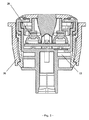
特にプラスチックの射出成形品から製造されているケース9内では、4つの接触子8が、このケース9の外部に向かって互いに並んで配置されていて、且つ屈曲させることによってこのケース9の内部に向かって四角形の4つの角に位置するように配置されている。当該四角形の4つの角に位置するような配置は、スイッチ要素1の内部に対称に配置される構造を可能にする。この場合、照明用の発光ダイオード及びそのスイッチが、中心に正確に配置され得る。これらの接触子8は、これらの接触子8ごとに対を成して同一部品として形成されている。このため、機器経費及び労働経費が削減され得る。これらの接触子8は、当該屈曲によってそのインサート成形された領域内に蛇行構造体を形成する。当該蛇行構造体は、ケース9内のプラグの押圧力に対する保護手段として機械的な固定を確実に達成し、水の浸入時の浸透経路が長くなる。同時に、接着剤が、当該インサート成形された領域内で接触子8を包囲するように塗布されてもよい。これにより、密封されたインサート成形が可能である。当該接触子8は、プラグを接続することによって接触される。この場合、一般に公知のその他の接続技術が使用されてもよい。圧力調整要素7(図3)が、ケース9の内側領域内に収容される。この圧力調整要素7は、熱間溶接又は超音波溶接によって、防水及び防塵式に固定される。スイッチ要素1の内部と外部の周囲条件との間の圧力補正が、ケース9内の、外側に向かって開口されている蛇行状の通気路13によって実施される。ケース9上に取り付けられ、同時に通気路13用の保護カバーを形成するフレーム10と協働して、圧力調整要素7が、外部の影響による損傷から保護される。第2の圧力調整要素又は別の容積補正要素が、例えばシリコン隔壁として、構造上対称な構成によって対向する側面に対して固定されてもよい。当該第2の圧力調整要素又は別の容積補正要素は、スイッチ要素1の操作時に、当該圧力調整要素が密封されているために圧縮される容積を補正する、すなわち当該補正がなければ弱まる空気の圧縮作用を補うように作用し、ひいては触覚特性を最適化する。
In particular, in the case 9 manufactured from a plastic injection-molded product, the four contacts 8 are arranged side by side toward the outside of the case 9 and are bent to be inside the case 9. It is arranged so as to be positioned at four corners of the quadrilateral. Arrangements such as those located at the four corners of the quadrangle allow a structure to be arranged symmetrically inside the
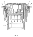
ケース9は、防水形プラグを収容するために適するプラグ用外殻14と一体的に形成されている。このケース9(図4)は、ガイド4のガイド輪郭16に一致する少なくとも3つのガイド溝15を有する。可能な限り長いガイドの場合に、短い装着深さ及びコンパクトな構造を実現するため、プラグ用外殻14が、防水用プラグを収容するためにスイッチ要素1の内側に向かって突出し、且つこれらの外部溝15が、外側に向かって当該プラグ用外殻から突出するように、これらのガイド溝15は、ケース9内に構造的に構成されている。この構造上の対策のさらなる利点は、圧力調整要素7用の収容領域とプリント基板6とが、ケース9の上側の開口部の近くに存在する点にある。このため、圧力調整要素7の最適な熱間溶接又は超音波溶接と、例えば半田接続によるプリント基板6に対する良好な結合とが達成される。別の結合技術、例えば接着も、圧力調整要素7を固定するために可能である。
The case 9 is formed integrally with a plug
ガイド4は、少なくとも3つの強固な端部ストッパ18を有する。これらの端部ストッパ18は、T字形の輪郭を成してガイド輪郭16の上方に形成されていて、スイッチ要素1を操作方向に操作するときにケース9の端部ストッパ17に当接する結果、このスイッチ要素1の最終位置を確定する。操作方向の少なくとも250ニュートンの誤操作時の力が、このスイッチ要素1の当該強固に形成された端部ストッパによって吸収され得る、つまりこのスイッチ要素の接触子に負荷がかかることなしに、且つこのスイッチ要素1の各構成要素を損傷することなしに吸収され得る。
The
当該スイッチ要素1は、フレーム10の外面に配置された3つの係止要素19によって取り付けベゼル11の固定要素に押さえ付けられる。したがって、スイッチ要素1の高さが、その取り付けられた状態で一定に形成されるように、フレーム10と取り付けベゼル11とが、それらの形状的に安定な輪郭にわたって当接する。当該高さの誤差が、取り付けベゼル11の係止フック20の斜角によって補正される。スイッチ要素1のコンパクトな構造が、当該弾性的な係止フック20を取り付けベゼル11に構造的に配置することによって得られる。何故なら、さもなければ、当該弾性的な係止フックの曲り撓みに備えるために、設置スペースが、スイッチ要素1に確保される必要があるからである。隣接した構造部品に対する電磁両立性を保証するため、当該係止結合部材は、好ましくはプラスチックから製作されている。したがって、当該設計は、例えば、電気自動車の外側領域内の充電キャップでの使用に適する。異なるスイッチ要素で使用するときに、取り付けベゼル11内への誤接続を回避するため、メカニカルコーディングが、フレーム10と取り付けベゼル11との間に設けられ得る。スイッチ要素1を取り付けベゼル11から取り外し可能であることを保証するため、或る輪郭が係止フック20に形成されている。この輪郭では、当該係止フック20が曲げて開かれ得る。したがって、スイッチ要素1が、取り付けベゼル11から取り外され得る。この設計の別の利点は、スイッチ要素1の取り付け方向と固定方向とが同じである点にある。これにより、このスイッチ要素1は、その操作ごとに最終位置に押圧され、その取り付け状態からの取り外れが起こり得ない。
The
図5は、キャップ2の斜視図である。周囲条件に対するスイッチ要素1の密封、凍結に対するロバスト性、スイッチ要素1の並進運動並びに探照灯21及び機能照明22を実現するため、このキャップ2は、複数要素射出成形法で製造されている。探照灯21の記号が、交換可能なインサートによって射出成形中に様々なバリエーションで製作され得、特に透光性の白色の材料で製作されている。機能灯22が、透光性で且つサブサーフィス散乱する材料で製造されていて、操作面23が、透光性の黒色の材料で製造されていて、保護隔壁12が、フレキシブルな黒色のプラスチック材料で製造されている。別の材料及び色彩も可能である。使用者に操作領域を示すため、例えば、保護隔壁12は、操作面23と異なる色で形成され得る。保護隔壁12の透過性の構造では、この保護隔壁12は、例えば、電気自動車の充電状態を示すために光を透過させてもよい。
FIG. 5 is a perspective view of the
したがって、全ての要素が、射出成形工程中の溶融によって、及びメカロックによって互いに固着し、一体的に且つ防水及び防塵式に互いに結合されている。当該キャップ2が、形成された係止要素を介してガイド4に取り付けられる。当該保護隔壁12が、プレストレスによってケース9の縁部上にわたって取り付けられる。その結果、当該保護隔壁12は、ケース9に一体的に密接する。プラグ側からケース9上に取り付けられるフレーム10と協働して、スイッチ要素1が密封される。したがって、密封輪郭25が、フレーム10の円周にわたって形成されているように、当該密封は、構造的に設計されている。この密封輪郭25は、弾性的な保護隔壁12に押し付けられ、その円周部分でケース9を一定の押圧力で引っ張る。当該円周部分にわたって迫上がり且つ外側に存在する縁部26が、この密封輪郭25(図6)から続いている。確実な取り付けが保証されるように、この縁部26は、フレーム10の取り付け時に保護隔壁12及び密封輪郭25を協働しいて位置決めする。したがって、さらに、当該取り付け工程を管理することが可能である。すなわち、フレーム10が、ケース9と保護隔壁12との間に挟持される結果、最終位置で遊びなしに嵌着する。保護隔壁12が、その外側の円周面に密封輪郭27を有するように、この保護隔壁12は構造的に形成されている。この密封輪郭27が、取り付け時に取り付けベゼル11にその外側で密着する結果、当該スイッチ要素をこの取り付けベゼル11に対して密接させる。したがって、さらに、スイッチ要素1を取り付けるために必要な取り付けベゼル11までの隙間が減少され、均質な全体像が、スイッチ要素1と取り付けベゼル11との間で得られる。このため、スイッチ要素1自体が、1つの密封部分だけによって保護され、取り付けベゼル11に対する密封も保証される。
Thus, all elements are secured to each other by melting during the injection molding process and by a mechanical lock and are joined together in a waterproof and dustproof manner. The
キャップ2の保護隔壁12が、その円周面を取り付けベゼル11の高さから出発してスイッチ要素1の最初の位置の方向に均等に上昇させるように形成されていることによって、このスイッチ要素1の凍結に対するロバスト性が実現される。したがって、当該上昇の高さは、少なくともスイッチ要素1の操作変位を示す。
The
スイッチ要素1の凍結時には、当該凍結は、キャップ2を操作することによって解除され、このキャップ2の並進運動が、切り替え用の電気信号に制限なしに変換される。当該スイッチ要素1の操作が、その凍結を解除するために、その復原も可能である。スイッチ要素1の操作面が、取り付けベゼルの高さに比べて高いために、手袋を用いて操作することも可能である。
When the
スイッチ系統を汚れ及び/又は液体から保護することを保証するため、圧力調整要素7とプリント基板6とシリコンマット5とガイド4と端部ストッパ2との収容領域が、ケース9とキャップ2との内部に完全に存在する。
In order to ensure that the switch system is protected from dirt and / or liquids, the accommodating area of the
シリコンマット5は、スイッチ要素1を復原するためと、探照灯21の光と機能灯22の光とを仕切るためとに使用される。押しボタンスイッチが、線形の力−変位特性を呈する少なくとも2つの復原ドーム構造体28(図3)によって均一な力で復原される。この代わりに、例えば、当該押しボタンスイッチに対する冗長性を保証するため、復原ドーム構造体28が、追加のスイッチ要素として使用されてもよい。別の構成では、当該押しボタンスイッチを、異なる力−変位特性で構成され得る、例えば、2段階又は3段階の力−変位特性で構成され得るシリコンマットに交換することが可能である。当該光の仕切りは、非透光性の材料を使用して探照灯21と機能灯22との間に雷文状の構造体を形成することによって実現される。端部ストッパ3が、スイッチ要素1の密封領域内に存在する、ケース9内の2つの凹部とプリント基板6上を押圧する弾性的なシリコンマット5との間に補強材として存在する。これにより、振動の影響下でも、スイッチ要素1の遊びなしで且つガタツキなしの構造が得られる。複数の端部ストッパが、シリコンマット28と押しボタンスイッチとの復原ドーム構造体の真上に存在するように、これらの端部ストッパは構造的に配置されている。押圧力が、保護隔壁12に印加されることなしに、これらの端部ストッパは、静止状態ではスイッチ要素1を保持する。したがって、この保護隔壁は、応力のない状態にある。当該状態は、触覚特性と視覚特性と寿命とに有効に作用する。
The silicon mat 5 is used to restore the
1 スイッチ要素
2 キャップ
3 端部ストッパ
4 ガイド
5 シリコンマット
6 プリント基板
7 圧力調整要素
8 接触子
9 ケース
10 フレーム
11 取り付けベゼル
12 保護隔壁
13 通気路
14 プラグ用外殻
15 ケースのガイド溝
16 ガイドのガイド輪郭
17 操作方向にあるケース内の端部ストッパ
18 操作方向にあるガイド内の端部ストッパ
19 フレームに当接する係止要素
20 取り付けベゼルに当接する係止フック
21 探照灯
22 機能灯
23 操作面
24 ケースの縁部
25 フレームの密封輪郭
26 フレームの縁部
27 取り付けベゼルに対する密封輪郭
28 シリコンマットの復原ドーム構造体
DESCRIPTION OF
Claims (18)
前記スイッチ要素は、そのケース(9)の内部に、少なくとも4つの接触子(8)と、1つの圧力調整要素(7)と、1つのプリント基板(6)と、復原要素及び光仕切り要素としての1つのシリコンマット(5)と、1つのガイド(4)と、1つの端部ストッパ(3)と、成形された保護隔壁(12)を有する1つのキャップ(2)と、1つのフレーム(10)とを有し、前記少なくとも4つの接触子のうちの少なくとも2つの接触子が、同じ輪郭を成して形成されていて、当該4つの接触子(8)は、そのプラグ領域内での直線状の配置が、前記ケースの内部では当該4つの接触子を四角形の4つの角に設ける配置になるように屈曲されていて、少なくとも1つの押しボタンスイッチ及び少なくとも2つの照明器具が、前記プリント基板(6)上に配置されていることを特徴とするスイッチ要素。 A waterproof and dust-proof type having a case and a cap slidable in the axial direction by a stroke distance between two final positions in the case for converting the linear motion of the pushbutton switch into an electrical signal for switching. An illumination switch element, wherein the cap has a protective partition that seals against the outside, the protective partition being made of a flexible plastic material by a multi-element injection molding process,
The switch element includes at least four contacts (8), one pressure adjusting element (7), one printed circuit board (6), a restoration element and a light partition element inside the case (9). One silicon mat (5), one guide (4), one end stopper (3), one cap (2) having a molded protective partition (12), and one frame ( 10), and at least two of the at least four contacts are formed with the same contour, and the four contacts (8) are within the plug region. The linear arrangement is bent so that the four contacts are arranged at the four corners of the quadrilateral inside the case, and at least one push button switch and at least two luminaires are arranged on the print. substrate Switch elements, characterized in that it is arranged on the 6).
Applications Claiming Priority (3)
| Application Number | Priority Date | Filing Date | Title |
|---|---|---|---|
| DE102011118178A DE102011118178B3 (en) | 2011-11-10 | 2011-11-10 | Illuminated, water and dustproof switching element |
| DE102011118178.8 | 2011-11-10 | ||
| PCT/DE2012/000991 WO2013067984A1 (en) | 2011-11-10 | 2012-10-11 | Illuminated, water- and dust-proof switching element |
Publications (2)
| Publication Number | Publication Date |
|---|---|
| JP2014532973A true JP2014532973A (en) | 2014-12-08 |
| JP2014532973A5 JP2014532973A5 (en) | 2016-11-17 |
Family
ID=47148554
Family Applications (1)
| Application Number | Title | Priority Date | Filing Date |
|---|---|---|---|
| JP2014540314A Ceased JP2014532973A (en) | 2011-11-10 | 2012-10-11 | Waterproof and dustproof illumination switch elements |
Country Status (7)
| Country | Link |
|---|---|
| US (1) | US9368297B2 (en) |
| EP (1) | EP2777056B8 (en) |
| JP (1) | JP2014532973A (en) |
| KR (1) | KR20140101770A (en) |
| CN (1) | CN103946941A (en) |
| DE (2) | DE102011118178B3 (en) |
| WO (1) | WO2013067984A1 (en) |
Families Citing this family (10)
| Publication number | Priority date | Publication date | Assignee | Title |
|---|---|---|---|---|
| KR20160125848A (en) * | 2015-04-22 | 2016-11-01 | 엘에스산전 주식회사 | Control box for electric vehicle charger |
| US10204750B2 (en) * | 2016-11-04 | 2019-02-12 | Carling Technologies, Inc. | Illuminated switch actuator further surrounded by an illumination structure |
| JP6770548B2 (en) | 2018-04-05 | 2020-10-14 | 株式会社東海理化電機製作所 | Switch device |
| JP6936760B2 (en) | 2018-04-05 | 2021-09-22 | 株式会社東海理化電機製作所 | Switch device |
| CN109296985A (en) * | 2018-09-27 | 2019-02-01 | 南通三辉电子有限公司 | A kind of automobile combined switch polychromatic light anti-scatter light guide column structure |
| IT201900002129A1 (en) * | 2019-02-14 | 2020-08-14 | Bticino Spa | Modular electronic device for electrical and / or home automation systems |
| DE102019104728A1 (en) * | 2019-02-25 | 2020-08-27 | Nidec Gpm Gmbh | Pump unit comprising a plug connector with pressure compensation element |
| FR3105557B1 (en) * | 2019-12-20 | 2022-03-18 | Legrand France | Waterproof electrical switch |
| GB2591263A (en) * | 2020-01-23 | 2021-07-28 | Continental Automotive Gmbh | IP69 Protection Illumination Push Button |
| KR20210108618A (en) * | 2020-02-26 | 2021-09-03 | 현대자동차주식회사 | Structure for a Switch and the Method thereof |
Citations (2)
| Publication number | Priority date | Publication date | Assignee | Title |
|---|---|---|---|---|
| JP2000173386A (en) * | 1998-12-09 | 2000-06-23 | Sanyo Electric Co Ltd | Push button device |
| EP1233434A2 (en) * | 2001-02-14 | 2002-08-21 | Whirlpool Corporation | Pushbutton structure for electronic, electrical and/or mechanical appalications |
Family Cites Families (14)
| Publication number | Priority date | Publication date | Assignee | Title |
|---|---|---|---|---|
| DE3519872A1 (en) * | 1985-06-03 | 1986-12-04 | Zwicker + Hensel Elektronische Schalttechnik GmbH, 5960 Olpe | Disk switching pressure initiator |
| DE8630188U1 (en) | 1986-11-11 | 1987-07-30 | Schurter Gmbh, 7833 Endingen, De | |
| DE8714573U1 (en) * | 1987-11-02 | 1988-01-14 | Motsch, Alfons, Dipl.-Ing., 5276 Wiehl, De | |
| CN2874746Y (en) * | 2005-12-29 | 2007-02-28 | 富士康(昆山)电脑接插件有限公司 | Switch |
| DE102008034046B4 (en) * | 2007-07-26 | 2020-08-13 | Marquardt Gmbh | Electric switch |
| AU2008323604B2 (en) * | 2007-11-12 | 2013-08-01 | Clipsal Australia Pty Ltd | Electric switch unit |
| DE102008015111B3 (en) | 2008-01-31 | 2009-06-10 | Preh Gmbh | Fluid protected control element for use in motor vehicle, has guide and groove walls extending in direction of rotary knob and pushbutton, and downpipe guiding fluid striking on guide plate onto printed circuit board's oppositely lying side |
| EP2175462B1 (en) * | 2008-10-10 | 2013-12-11 | RAFI GmbH & Co. KG | Sealed switch |
| CN201298476Y (en) * | 2008-11-06 | 2009-08-26 | 深圳市航盛电子股份有限公司 | Seal-fitting type push-button switch device |
| DE102009008537B3 (en) | 2009-02-11 | 2010-02-25 | Siemens Aktiengesellschaft | pushbutton |
| DE102009029825B3 (en) | 2009-06-18 | 2010-10-28 | Gigaset Communications Gmbh | Button i.e. rocker button, arrangement for use in side area of mobile telephone utilized in e.g. audio-and/or video entertainment technology, has sealing element fixed at housing via clamping element, which is fixed at resting nose |
| DE102010008809C5 (en) | 2009-12-18 | 2016-01-07 | Helmut Birkelbach | Film capacitor and method for producing a film capacitor |
| TWM400080U (en) | 2010-09-09 | 2011-03-11 | jin-xiong Chu | Structure improvement of pressing-type switch |
| DE102011000112A1 (en) | 2011-01-13 | 2012-07-19 | Bundesdruckerei Gmbh | Method for verifying personal data in customer traffic |
-
2011
- 2011-11-10 DE DE102011118178A patent/DE102011118178B3/en not_active Expired - Fee Related
-
2012
- 2012-10-11 CN CN201280055101.8A patent/CN103946941A/en active Pending
- 2012-10-11 EP EP12783858.9A patent/EP2777056B8/en not_active Not-in-force
- 2012-10-11 WO PCT/DE2012/000991 patent/WO2013067984A1/en active Application Filing
- 2012-10-11 DE DE112012004712.5T patent/DE112012004712A5/en not_active Withdrawn
- 2012-10-11 KR KR1020147015754A patent/KR20140101770A/en not_active Application Discontinuation
- 2012-10-11 US US14/357,716 patent/US9368297B2/en not_active Expired - Fee Related
- 2012-10-11 JP JP2014540314A patent/JP2014532973A/en not_active Ceased
Patent Citations (2)
| Publication number | Priority date | Publication date | Assignee | Title |
|---|---|---|---|---|
| JP2000173386A (en) * | 1998-12-09 | 2000-06-23 | Sanyo Electric Co Ltd | Push button device |
| EP1233434A2 (en) * | 2001-02-14 | 2002-08-21 | Whirlpool Corporation | Pushbutton structure for electronic, electrical and/or mechanical appalications |
Also Published As
| Publication number | Publication date |
|---|---|
| EP2777056A1 (en) | 2014-09-17 |
| KR20140101770A (en) | 2014-08-20 |
| EP2777056B8 (en) | 2017-01-04 |
| WO2013067984A1 (en) | 2013-05-16 |
| US20150060245A1 (en) | 2015-03-05 |
| CN103946941A (en) | 2014-07-23 |
| US9368297B2 (en) | 2016-06-14 |
| DE112012004712A5 (en) | 2014-09-04 |
| EP2777056B1 (en) | 2016-11-09 |
| DE102011118178B3 (en) | 2013-05-16 |
Similar Documents
| Publication | Publication Date | Title |
|---|---|---|
| JP2014532973A (en) | Waterproof and dustproof illumination switch elements | |
| JP2014532973A5 (en) | ||
| US7938460B2 (en) | Latch release operating apparatus | |
| US7759592B2 (en) | Seal for electrical switch pad | |
| US6573466B1 (en) | Electrical switch | |
| US7485824B2 (en) | Electrical switch component | |
| EP2418668B1 (en) | Push switch | |
| JP2002529897A5 (en) | ||
| TW201706756A (en) | Water-proof notebook computer | |
| US20110308925A1 (en) | Push switch | |
| CN114450184A (en) | Charging or refueling recess | |
| JP6045114B2 (en) | Waterproof dustproof switch | |
| JP2015165496A (en) | Water-tight micro-switch | |
| ES2948770T3 (en) | A snap-action switch and mounting method thereof | |
| JP2020020109A (en) | Back door handle device and manufacturing method therefor | |
| TWI449069B (en) | Waterproof micro switch | |
| KR101789925B1 (en) | Push button switch assembly and manufacturing method thereof | |
| KR101624729B1 (en) | Door Antenna Switch for Vehicle | |
| KR101816776B1 (en) | Push switch | |
| US9536688B2 (en) | Press button device and audio equipment having the press button device | |
| CN215344727U (en) | Shell subassembly and have its thermal imaging camera | |
| US8178807B2 (en) | Electrical switch | |
| JP2012134075A (en) | Push switch | |
| US11862425B2 (en) | Switch device, and opening and closing detection device | |
| JP3913058B2 (en) | Structure of portable radio |
Legal Events
| Date | Code | Title | Description |
|---|---|---|---|
| A521 | Request for written amendment filed |
Free format text: JAPANESE INTERMEDIATE CODE: A523 Effective date: 20150708 |
|
| A621 | Written request for application examination |
Free format text: JAPANESE INTERMEDIATE CODE: A621 Effective date: 20150708 |
|
| A977 | Report on retrieval |
Free format text: JAPANESE INTERMEDIATE CODE: A971007 Effective date: 20160425 |
|
| A131 | Notification of reasons for refusal |
Free format text: JAPANESE INTERMEDIATE CODE: A131 Effective date: 20160427 |
|
| A601 | Written request for extension of time |
Free format text: JAPANESE INTERMEDIATE CODE: A601 Effective date: 20160725 |
|
| A524 | Written submission of copy of amendment under article 19 pct |
Free format text: JAPANESE INTERMEDIATE CODE: A524 Effective date: 20160921 |
|
| A521 | Request for written amendment filed |
Free format text: JAPANESE INTERMEDIATE CODE: A523 Effective date: 20160923 |
|
| A01 | Written decision to grant a patent or to grant a registration (utility model) |
Free format text: JAPANESE INTERMEDIATE CODE: A01 Effective date: 20170222 |
|
| A045 | Written measure of dismissal of application [lapsed due to lack of payment] |
Free format text: JAPANESE INTERMEDIATE CODE: A045 Effective date: 20170628 |