JP2010014087A - 電磁式燃料噴射弁及びその製造方法 - Google Patents
電磁式燃料噴射弁及びその製造方法 Download PDFInfo
- Publication number
- JP2010014087A JP2010014087A JP2008177056A JP2008177056A JP2010014087A JP 2010014087 A JP2010014087 A JP 2010014087A JP 2008177056 A JP2008177056 A JP 2008177056A JP 2008177056 A JP2008177056 A JP 2008177056A JP 2010014087 A JP2010014087 A JP 2010014087A
- Authority
- JP
- Japan
- Prior art keywords
- cylindrical body
- valve
- nonmagnetic
- magnetic
- fixed core
- Prior art date
- Legal status (The legal status is an assumption and is not a legal conclusion. Google has not performed a legal analysis and makes no representation as to the accuracy of the status listed.)
- Granted
Links
Images

Classifications
-
- F—MECHANICAL ENGINEERING; LIGHTING; HEATING; WEAPONS; BLASTING
- F02—COMBUSTION ENGINES; HOT-GAS OR COMBUSTION-PRODUCT ENGINE PLANTS
- F02M—SUPPLYING COMBUSTION ENGINES IN GENERAL WITH COMBUSTIBLE MIXTURES OR CONSTITUENTS THEREOF
- F02M61/00—Fuel-injectors not provided for in groups F02M39/00 - F02M57/00 or F02M67/00
- F02M61/16—Details not provided for in, or of interest apart from, the apparatus of groups F02M61/02 - F02M61/14
- F02M61/18—Injection nozzles, e.g. having valve seats; Details of valve member seated ends, not otherwise provided for
- F02M61/1853—Orifice plates
-
- F—MECHANICAL ENGINEERING; LIGHTING; HEATING; WEAPONS; BLASTING
- F02—COMBUSTION ENGINES; HOT-GAS OR COMBUSTION-PRODUCT ENGINE PLANTS
- F02M—SUPPLYING COMBUSTION ENGINES IN GENERAL WITH COMBUSTIBLE MIXTURES OR CONSTITUENTS THEREOF
- F02M61/00—Fuel-injectors not provided for in groups F02M39/00 - F02M57/00 or F02M67/00
- F02M61/16—Details not provided for in, or of interest apart from, the apparatus of groups F02M61/02 - F02M61/14
- F02M61/168—Assembling; Disassembling; Manufacturing; Adjusting
-
- Y—GENERAL TAGGING OF NEW TECHNOLOGICAL DEVELOPMENTS; GENERAL TAGGING OF CROSS-SECTIONAL TECHNOLOGIES SPANNING OVER SEVERAL SECTIONS OF THE IPC; TECHNICAL SUBJECTS COVERED BY FORMER USPC CROSS-REFERENCE ART COLLECTIONS [XRACs] AND DIGESTS
- Y10—TECHNICAL SUBJECTS COVERED BY FORMER USPC
- Y10T—TECHNICAL SUBJECTS COVERED BY FORMER US CLASSIFICATION
- Y10T29/00—Metal working
- Y10T29/49—Method of mechanical manufacture
- Y10T29/49002—Electrical device making
- Y10T29/49009—Dynamoelectric machine
Landscapes
- Engineering & Computer Science (AREA)
- Chemical & Material Sciences (AREA)
- Combustion & Propulsion (AREA)
- Mechanical Engineering (AREA)
- General Engineering & Computer Science (AREA)
- Manufacturing & Machinery (AREA)
- Fuel-Injection Apparatus (AREA)
Abstract
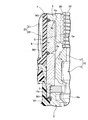
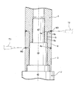
【解決手段】固定コア5の前端部には,非磁性円筒体4内に向かって突出する吸引筒部5aを突設して,この吸引筒部5aの前端と可動コア17の後端とを非磁性円筒体4内で相互に対向させた電磁式燃料噴射弁において,吸引筒部5aの外周面と非磁性円筒体4の内周面との間に,非磁性円筒体4及び固定コア5間の液密検査に使用する圧力流体の流入を許容する環状間隙Gを設けた。
【選択図】 図2
Description
G・・・・・環状間隙
J・・・・・治具
1・・・・・弁ハウジング
2・・・・・弁座部材
3・・・・・磁性円筒体
4・・・・・非磁性円筒体
4a・・・・テーパ面
5・・・・・固定コア
5a・・・・吸引筒部
8・・・・・弁座
15・・・・弁組立体
16・・・・弁体
17・・・・可動コア
46・・・・大径軸部
47・・・・小径軸部
Claims (3)
- 弁座(8)を前端部に有する筒状の弁座部材(2)と,この弁座部材(2)の後端部に同軸状に結合される磁性円筒体(3)と,この磁性円筒体(3)の後端に同軸状且つ液密に溶接される非磁性円筒体(4)と,非磁性円筒体(4)の後端に同軸状且つ液密に溶接される中空円筒状の固定コア(5)とで弁ハウジング(1)を構成し,この弁ハウジング(1)内に,前記弁座(8)に着座し得る弁体(16)と,この弁体(16)の後端に結合される可動コア(17)とで構成される弁組立体(15)を収容し,固定コア(5)の前端部には,非磁性円筒体(4)内に向かって突出する吸引筒部(5a)を突設して,この吸引筒部(5a)の前端と可動コア(17)の後端とを非磁性円筒体(4)内で相互に対向させた電磁式燃料噴射弁において,
前記吸引筒部(5a)の外周面と非磁性円筒体(4)の内周面との間に,非磁性円筒体(4)及び固定コア(5)間の液密検査に使用する圧力流体の流入を許容する環状間隙Gを設けたことを特徴とする電磁式燃料噴射弁。 - 請求項1記載の電磁式燃料噴射弁における磁性円筒体(3),非磁性円筒体(4)及び固定コア(5)の三者を溶接する際には,磁性円筒体(3)及び非磁性円筒体(4)の両内周面に密合し得る大径軸部(46)及び,固定コア(5)の内周面に密合し得る小径軸部(47)を相互に同軸状に結合してなる治具(J)を用意し,この治具(J)の大径軸部(46)の外周面に磁性円筒体(3)及び非磁性円筒体(4)の両内周面を密合すると共に,小径軸部(47)の外周面に固定コア(5)の内周面を密合した状態で,磁性円筒体(3),非磁性円筒体(4)及び固定コア(5)の三者の各軸方向突き当て部を溶接することを特徴とする,電磁式燃料噴射弁の製造方法。
- 請求項2記載の電磁式燃料噴射弁の製造方法において,
非磁性円筒体(4)の軸方向両端の内周縁部には,前記大径軸部(46)の非磁性円筒体(4)内への密合を誘導し得るテーパ面(4a,4a)を形成しておくことを特徴とする,電磁式燃料噴射弁の製造方法。
Priority Applications (3)
| Application Number | Priority Date | Filing Date | Title |
|---|---|---|---|
| JP2008177056A JP5072745B2 (ja) | 2008-07-07 | 2008-07-07 | 電磁式燃料噴射弁及びその製造方法 |
| US12/488,222 US8246005B2 (en) | 2008-07-07 | 2009-06-19 | Electromagnetic fuel injection valve and method of manufacturing the same |
| CN200910151051.3A CN101624954B (zh) | 2008-07-07 | 2009-07-07 | 电磁式燃料喷射阀及其制造方法 |
Applications Claiming Priority (1)
| Application Number | Priority Date | Filing Date | Title |
|---|---|---|---|
| JP2008177056A JP5072745B2 (ja) | 2008-07-07 | 2008-07-07 | 電磁式燃料噴射弁及びその製造方法 |
Publications (2)
| Publication Number | Publication Date |
|---|---|
| JP2010014087A true JP2010014087A (ja) | 2010-01-21 |
| JP5072745B2 JP5072745B2 (ja) | 2012-11-14 |
Family
ID=41463643
Family Applications (1)
| Application Number | Title | Priority Date | Filing Date |
|---|---|---|---|
| JP2008177056A Active JP5072745B2 (ja) | 2008-07-07 | 2008-07-07 | 電磁式燃料噴射弁及びその製造方法 |
Country Status (3)
| Country | Link |
|---|---|
| US (1) | US8246005B2 (ja) |
| JP (1) | JP5072745B2 (ja) |
| CN (1) | CN101624954B (ja) |
Cited By (1)
| Publication number | Priority date | Publication date | Assignee | Title |
|---|---|---|---|---|
| JP2012097721A (ja) * | 2010-11-05 | 2012-05-24 | Kumamoto Univ | インジェクションノズル |
Families Citing this family (5)
| Publication number | Priority date | Publication date | Assignee | Title |
|---|---|---|---|---|
| CN103184959B (zh) * | 2011-12-30 | 2017-01-18 | 联合汽车电子有限公司 | 衔铁‑针阀组件、其成型装配方法及装配工具 |
| DE102012210956A1 (de) * | 2012-06-27 | 2014-01-02 | Robert Bosch Gmbh | Verfahren zur Herstellung eines Gehäuses, insbesondere eines Ventilgehäuses |
| CN105658950B (zh) * | 2013-11-11 | 2018-11-06 | 恩普乐斯股份有限公司 | 燃料喷射装置用喷嘴板的安装构造 |
| WO2017168975A1 (ja) * | 2016-03-28 | 2017-10-05 | 日立オートモティブシステムズ株式会社 | 流量制御装置 |
| WO2019202829A1 (ja) * | 2018-04-20 | 2019-10-24 | 日立オートモティブシステムズ株式会社 | 流量制御装置の部品及び燃料噴射弁 |
Citations (4)
| Publication number | Priority date | Publication date | Assignee | Title |
|---|---|---|---|---|
| JP2003511604A (ja) * | 1999-10-07 | 2003-03-25 | ローベルト ボツシユ ゲゼルシヤフト ミツト ベシユレンクテル ハフツング | 燃料噴射弁 |
| JP2005240733A (ja) * | 2004-02-27 | 2005-09-08 | Keihin Corp | 電磁式燃料噴射弁およびその製造方法 |
| JP2005240732A (ja) * | 2004-02-27 | 2005-09-08 | Keihin Corp | 電磁式燃料噴射弁およびその製造方法 |
| WO2006035656A1 (ja) * | 2004-09-27 | 2006-04-06 | Keihin Corporation | 電磁式燃料噴射弁 |
Family Cites Families (12)
| Publication number | Priority date | Publication date | Assignee | Title |
|---|---|---|---|---|
| US2991347A (en) * | 1959-12-14 | 1961-07-04 | Hoffman Electronics Corp | Magnetic jig for alloying |
| JPS63235068A (ja) * | 1987-03-23 | 1988-09-30 | Toshiba Corp | ろう接用治具 |
| DE4008675A1 (de) * | 1990-03-17 | 1991-09-19 | Bosch Gmbh Robert | Elektromagnetisch betaetigbares ventil |
| DE4113682A1 (de) * | 1991-04-26 | 1992-10-29 | Bosch Gmbh Robert | Einspritzventil |
| JPH07289953A (ja) * | 1994-03-03 | 1995-11-07 | Nippondenso Co Ltd | 流体噴射ノズル |
| US5431331A (en) * | 1994-03-15 | 1995-07-11 | Ney; Robert | Thermal resilient multiple jaw braze fixture |
| US6676044B2 (en) * | 2000-04-07 | 2004-01-13 | Siemens Automotive Corporation | Modular fuel injector and method of assembling the modular fuel injector |
| JP3837283B2 (ja) * | 2000-10-24 | 2006-10-25 | 株式会社ケーヒン | 燃料噴射弁 |
| JP2003206820A (ja) * | 2002-01-17 | 2003-07-25 | Keihin Corp | 電磁式燃料噴射弁 |
| JP2005240731A (ja) * | 2004-02-27 | 2005-09-08 | Keihin Corp | 電磁式燃料噴射弁 |
| JP2006118415A (ja) * | 2004-10-21 | 2006-05-11 | Keihin Corp | 電磁式燃料噴射弁の製造方法 |
| CN101739084B (zh) * | 2008-11-25 | 2012-07-18 | 鸿富锦精密工业(深圳)有限公司 | 电子装置 |
-
2008
- 2008-07-07 JP JP2008177056A patent/JP5072745B2/ja active Active
-
2009
- 2009-06-19 US US12/488,222 patent/US8246005B2/en active Active
- 2009-07-07 CN CN200910151051.3A patent/CN101624954B/zh active Active
Patent Citations (5)
| Publication number | Priority date | Publication date | Assignee | Title |
|---|---|---|---|---|
| JP2003511604A (ja) * | 1999-10-07 | 2003-03-25 | ローベルト ボツシユ ゲゼルシヤフト ミツト ベシユレンクテル ハフツング | 燃料噴射弁 |
| JP2005240733A (ja) * | 2004-02-27 | 2005-09-08 | Keihin Corp | 電磁式燃料噴射弁およびその製造方法 |
| JP2005240732A (ja) * | 2004-02-27 | 2005-09-08 | Keihin Corp | 電磁式燃料噴射弁およびその製造方法 |
| WO2005083260A1 (ja) * | 2004-02-27 | 2005-09-09 | Keihin Corporation | 電磁式燃料噴射弁およびその製造方法 |
| WO2006035656A1 (ja) * | 2004-09-27 | 2006-04-06 | Keihin Corporation | 電磁式燃料噴射弁 |
Cited By (1)
| Publication number | Priority date | Publication date | Assignee | Title |
|---|---|---|---|---|
| JP2012097721A (ja) * | 2010-11-05 | 2012-05-24 | Kumamoto Univ | インジェクションノズル |
Also Published As
| Publication number | Publication date |
|---|---|
| CN101624954A (zh) | 2010-01-13 |
| US20100001214A1 (en) | 2010-01-07 |
| JP5072745B2 (ja) | 2012-11-14 |
| US8246005B2 (en) | 2012-08-21 |
| CN101624954B (zh) | 2012-07-04 |
Similar Documents
| Publication | Publication Date | Title |
|---|---|---|
| JP5072745B2 (ja) | 電磁式燃料噴射弁及びその製造方法 | |
| JP3837283B2 (ja) | 燃料噴射弁 | |
| KR101286437B1 (ko) | 가스 연료용 분사 밸브 | |
| JP2010014088A (ja) | 電磁式燃料噴射弁 | |
| JP5389560B2 (ja) | 電磁式燃料噴射弁 | |
| JP2004278464A (ja) | 燃料噴射弁 | |
| US11168656B2 (en) | Fuel injection valve and method for manufacturing fuel injection valve | |
| JP2010031674A (ja) | 電磁式燃料噴射弁 | |
| JP3803539B2 (ja) | 電磁式燃料噴射弁 | |
| JP3819741B2 (ja) | 電磁式燃料噴射弁 | |
| JP2010038109A (ja) | ガス燃料用噴射弁 | |
| US9103310B2 (en) | Fuel injector | |
| JP2008063952A (ja) | 電磁式燃料噴射弁 | |
| JP4669852B2 (ja) | 電磁式燃料噴射弁 | |
| JP2004068600A (ja) | 電磁式燃料噴射弁 | |
| US10247158B2 (en) | Fuel injection valve | |
| JP3837300B2 (ja) | 燃料噴射弁におけるエアアシストキャップの位置決め構造 | |
| JP7269155B2 (ja) | 電磁式燃料噴射弁 | |
| JP2002081356A (ja) | 電磁式燃料噴射弁 | |
| CN109642527B (zh) | 燃料喷射阀 | |
| JP6655575B2 (ja) | 電磁式燃料噴射弁 | |
| JP6817927B2 (ja) | 燃料噴射弁 | |
| JP2020161809A (ja) | ソレノイドチューブの製造方法 | |
| JP2001193608A (ja) | 燃料噴射弁の弁ハウジング及びその製造方法 | |
| JP2004060534A (ja) | 燃料噴射弁のoリング取り付け構造 |
Legal Events
| Date | Code | Title | Description |
|---|---|---|---|
| A621 | Written request for application examination |
Free format text: JAPANESE INTERMEDIATE CODE: A621 Effective date: 20110415 |
|
| A977 | Report on retrieval |
Free format text: JAPANESE INTERMEDIATE CODE: A971007 Effective date: 20120727 |
|
| TRDD | Decision of grant or rejection written | ||
| A01 | Written decision to grant a patent or to grant a registration (utility model) |
Free format text: JAPANESE INTERMEDIATE CODE: A01 Effective date: 20120801 |
|
| A01 | Written decision to grant a patent or to grant a registration (utility model) |
Free format text: JAPANESE INTERMEDIATE CODE: A01 |
|
| A61 | First payment of annual fees (during grant procedure) |
Free format text: JAPANESE INTERMEDIATE CODE: A61 Effective date: 20120821 |
|
| R150 | Certificate of patent or registration of utility model |
Ref document number: 5072745 Country of ref document: JP Free format text: JAPANESE INTERMEDIATE CODE: R150 Free format text: JAPANESE INTERMEDIATE CODE: R150 |
|
| FPAY | Renewal fee payment (event date is renewal date of database) |
Free format text: PAYMENT UNTIL: 20150831 Year of fee payment: 3 |
|
| R250 | Receipt of annual fees |
Free format text: JAPANESE INTERMEDIATE CODE: R250 |
|
| R250 | Receipt of annual fees |
Free format text: JAPANESE INTERMEDIATE CODE: R250 |
|
| R250 | Receipt of annual fees |
Free format text: JAPANESE INTERMEDIATE CODE: R250 |
|
| R250 | Receipt of annual fees |
Free format text: JAPANESE INTERMEDIATE CODE: R250 |
|
| R250 | Receipt of annual fees |
Free format text: JAPANESE INTERMEDIATE CODE: R250 |
|
| R250 | Receipt of annual fees |
Free format text: JAPANESE INTERMEDIATE CODE: R250 |
|
| S111 | Request for change of ownership or part of ownership |
Free format text: JAPANESE INTERMEDIATE CODE: R313111 |
|
| R350 | Written notification of registration of transfer |
Free format text: JAPANESE INTERMEDIATE CODE: R350 |
|
| R250 | Receipt of annual fees |
Free format text: JAPANESE INTERMEDIATE CODE: R250 |
|
| R250 | Receipt of annual fees |
Free format text: JAPANESE INTERMEDIATE CODE: R250 |
|
| R250 | Receipt of annual fees |
Free format text: JAPANESE INTERMEDIATE CODE: R250 |