JP2009509338A - Method for forming SiCMOSFET having large inversion layer mobility - Google Patents
Method for forming SiCMOSFET having large inversion layer mobility Download PDFInfo
- Publication number
- JP2009509338A JP2009509338A JP2008531214A JP2008531214A JP2009509338A JP 2009509338 A JP2009509338 A JP 2009509338A JP 2008531214 A JP2008531214 A JP 2008531214A JP 2008531214 A JP2008531214 A JP 2008531214A JP 2009509338 A JP2009509338 A JP 2009509338A
- Authority
- JP
- Japan
- Prior art keywords
- silicon carbide
- region
- annealing
- layer
- type
- Prior art date
- Legal status (The legal status is an assumption and is not a legal conclusion. Google has not performed a legal analysis and makes no representation as to the accuracy of the status listed.)
- Granted
Links
- 238000000034 method Methods 0.000 title claims abstract description 78
- 229910010271 silicon carbide Inorganic materials 0.000 claims abstract description 97
- HBMJWWWQQXIZIP-UHFFFAOYSA-N silicon carbide Chemical compound [Si+]#[C-] HBMJWWWQQXIZIP-UHFFFAOYSA-N 0.000 claims abstract description 93
- 238000000137 annealing Methods 0.000 claims abstract description 63
- 239000012298 atmosphere Substances 0.000 claims abstract description 29
- QVGXLLKOCUKJST-UHFFFAOYSA-N atomic oxygen Chemical compound [O] QVGXLLKOCUKJST-UHFFFAOYSA-N 0.000 claims description 20
- 229910052760 oxygen Inorganic materials 0.000 claims description 20
- 239000001301 oxygen Substances 0.000 claims description 20
- PNEYBMLMFCGWSK-UHFFFAOYSA-N aluminium oxide Inorganic materials [O-2].[O-2].[O-2].[Al+3].[Al+3] PNEYBMLMFCGWSK-UHFFFAOYSA-N 0.000 claims description 18
- 239000012535 impurity Substances 0.000 claims description 14
- 239000011248 coating agent Substances 0.000 claims description 8
- 238000000576 coating method Methods 0.000 claims description 8
- 238000005229 chemical vapour deposition Methods 0.000 claims description 6
- 229910021420 polycrystalline silicon Inorganic materials 0.000 claims description 6
- 229920005591 polysilicon Polymers 0.000 claims description 6
- 229910052751 metal Inorganic materials 0.000 claims description 5
- 239000002184 metal Substances 0.000 claims description 5
- VYPSYNLAJGMNEJ-UHFFFAOYSA-N Silicium dioxide Chemical compound O=[Si]=O VYPSYNLAJGMNEJ-UHFFFAOYSA-N 0.000 abstract description 5
- 229910052814 silicon oxide Inorganic materials 0.000 abstract 1
- MWUXSHHQAYIFBG-UHFFFAOYSA-N Nitric oxide Chemical compound O=[N] MWUXSHHQAYIFBG-UHFFFAOYSA-N 0.000 description 58
- 235000012431 wafers Nutrition 0.000 description 33
- 230000008569 process Effects 0.000 description 26
- 238000007254 oxidation reaction Methods 0.000 description 17
- 230000003647 oxidation Effects 0.000 description 15
- 239000002019 doping agent Substances 0.000 description 14
- 150000002500 ions Chemical class 0.000 description 13
- 238000010405 reoxidation reaction Methods 0.000 description 11
- 229910052782 aluminium Inorganic materials 0.000 description 10
- XAGFODPZIPBFFR-UHFFFAOYSA-N aluminium Chemical compound [Al] XAGFODPZIPBFFR-UHFFFAOYSA-N 0.000 description 10
- 239000000758 substrate Substances 0.000 description 10
- IJGRMHOSHXDMSA-UHFFFAOYSA-N Atomic nitrogen Chemical compound N#N IJGRMHOSHXDMSA-UHFFFAOYSA-N 0.000 description 8
- PXHVJJICTQNCMI-UHFFFAOYSA-N Nickel Chemical compound [Ni] PXHVJJICTQNCMI-UHFFFAOYSA-N 0.000 description 8
- 239000000463 material Substances 0.000 description 7
- 238000002513 implantation Methods 0.000 description 6
- 238000004519 manufacturing process Methods 0.000 description 6
- 239000004065 semiconductor Substances 0.000 description 6
- 229910004298 SiO 2 Inorganic materials 0.000 description 5
- XEEYBQQBJWHFJM-UHFFFAOYSA-N iron Substances [Fe] XEEYBQQBJWHFJM-UHFFFAOYSA-N 0.000 description 5
- 238000005259 measurement Methods 0.000 description 5
- 238000004458 analytical method Methods 0.000 description 4
- 238000009792 diffusion process Methods 0.000 description 4
- 238000005468 ion implantation Methods 0.000 description 4
- 229910052759 nickel Inorganic materials 0.000 description 4
- 229910052757 nitrogen Inorganic materials 0.000 description 4
- 238000004151 rapid thermal annealing Methods 0.000 description 4
- ZOXJGFHDIHLPTG-UHFFFAOYSA-N Boron Chemical compound [B] ZOXJGFHDIHLPTG-UHFFFAOYSA-N 0.000 description 3
- XUIMIQQOPSSXEZ-UHFFFAOYSA-N Silicon Chemical compound [Si] XUIMIQQOPSSXEZ-UHFFFAOYSA-N 0.000 description 3
- 229910052796 boron Inorganic materials 0.000 description 3
- 230000008859 change Effects 0.000 description 3
- 238000010586 diagram Methods 0.000 description 3
- 238000009826 distribution Methods 0.000 description 3
- 230000005669 field effect Effects 0.000 description 3
- 229910052742 iron Inorganic materials 0.000 description 3
- 229910052710 silicon Inorganic materials 0.000 description 3
- 239000010703 silicon Substances 0.000 description 3
- 235000012239 silicon dioxide Nutrition 0.000 description 3
- OAICVXFJPJFONN-UHFFFAOYSA-N Phosphorus Chemical compound [P] OAICVXFJPJFONN-UHFFFAOYSA-N 0.000 description 2
- 230000008901 benefit Effects 0.000 description 2
- 238000011109 contamination Methods 0.000 description 2
- 230000005684 electric field Effects 0.000 description 2
- 230000006872 improvement Effects 0.000 description 2
- 238000011065 in-situ storage Methods 0.000 description 2
- 230000005527 interface trap Effects 0.000 description 2
- 229910021421 monocrystalline silicon Inorganic materials 0.000 description 2
- 229910052698 phosphorus Inorganic materials 0.000 description 2
- 239000011574 phosphorus Substances 0.000 description 2
- 238000012545 processing Methods 0.000 description 2
- 239000010453 quartz Substances 0.000 description 2
- 238000012951 Remeasurement Methods 0.000 description 1
- 238000009825 accumulation Methods 0.000 description 1
- 230000003213 activating effect Effects 0.000 description 1
- 229910001423 beryllium ion Inorganic materials 0.000 description 1
- 238000009529 body temperature measurement Methods 0.000 description 1
- 239000003990 capacitor Substances 0.000 description 1
- 230000015556 catabolic process Effects 0.000 description 1
- 239000013078 crystal Substances 0.000 description 1
- 238000002484 cyclic voltammetry Methods 0.000 description 1
- 238000001514 detection method Methods 0.000 description 1
- 238000011161 development Methods 0.000 description 1
- 239000003989 dielectric material Substances 0.000 description 1
- 230000000694 effects Effects 0.000 description 1
- 238000005516 engineering process Methods 0.000 description 1
- 238000000605 extraction Methods 0.000 description 1
- 238000002347 injection Methods 0.000 description 1
- 239000007924 injection Substances 0.000 description 1
- 239000012212 insulator Substances 0.000 description 1
- 230000002427 irreversible effect Effects 0.000 description 1
- 230000007246 mechanism Effects 0.000 description 1
- 229910044991 metal oxide Inorganic materials 0.000 description 1
- 150000004706 metal oxides Chemical class 0.000 description 1
- 238000002488 metal-organic chemical vapour deposition Methods 0.000 description 1
- 239000012299 nitrogen atmosphere Substances 0.000 description 1
- 230000001590 oxidative effect Effects 0.000 description 1
- 230000003071 parasitic effect Effects 0.000 description 1
- 238000002161 passivation Methods 0.000 description 1
- -1 phosphorous ions Chemical class 0.000 description 1
- 230000000704 physical effect Effects 0.000 description 1
- 230000009467 reduction Effects 0.000 description 1
- 238000011160 research Methods 0.000 description 1
- 230000035945 sensitivity Effects 0.000 description 1
- 239000000377 silicon dioxide Substances 0.000 description 1
- 238000005245 sintering Methods 0.000 description 1
- 238000010408 sweeping Methods 0.000 description 1
- 238000012360 testing method Methods 0.000 description 1
- 238000003949 trap density measurement Methods 0.000 description 1
- 238000007740 vapor deposition Methods 0.000 description 1
- XLYOFNOQVPJJNP-UHFFFAOYSA-N water Chemical compound O XLYOFNOQVPJJNP-UHFFFAOYSA-N 0.000 description 1
- 238000009279 wet oxidation reaction Methods 0.000 description 1
Images


Classifications
-
- H—ELECTRICITY
- H01—ELECTRIC ELEMENTS
- H01L—SEMICONDUCTOR DEVICES NOT COVERED BY CLASS H10
- H01L29/00—Semiconductor devices adapted for rectifying, amplifying, oscillating or switching, or capacitors or resistors with at least one potential-jump barrier or surface barrier, e.g. PN junction depletion layer or carrier concentration layer; Details of semiconductor bodies or of electrodes thereof ; Multistep manufacturing processes therefor
- H01L29/66—Types of semiconductor device ; Multistep manufacturing processes therefor
- H01L29/68—Types of semiconductor device ; Multistep manufacturing processes therefor controllable by only the electric current supplied, or only the electric potential applied, to an electrode which does not carry the current to be rectified, amplified or switched
- H01L29/76—Unipolar devices, e.g. field effect transistors
- H01L29/772—Field effect transistors
- H01L29/78—Field effect transistors with field effect produced by an insulated gate
- H01L29/7801—DMOS transistors, i.e. MISFETs with a channel accommodating body or base region adjoining a drain drift region
- H01L29/7802—Vertical DMOS transistors, i.e. VDMOS transistors
-
- H—ELECTRICITY
- H01—ELECTRIC ELEMENTS
- H01L—SEMICONDUCTOR DEVICES NOT COVERED BY CLASS H10
- H01L21/00—Processes or apparatus adapted for the manufacture or treatment of semiconductor or solid state devices or of parts thereof
- H01L21/02—Manufacture or treatment of semiconductor devices or of parts thereof
- H01L21/02104—Forming layers
- H01L21/02107—Forming insulating materials on a substrate
- H01L21/02225—Forming insulating materials on a substrate characterised by the process for the formation of the insulating layer
- H01L21/02227—Forming insulating materials on a substrate characterised by the process for the formation of the insulating layer formation by a process other than a deposition process
- H01L21/0223—Forming insulating materials on a substrate characterised by the process for the formation of the insulating layer formation by a process other than a deposition process formation by oxidation, e.g. oxidation of the substrate
- H01L21/02233—Forming insulating materials on a substrate characterised by the process for the formation of the insulating layer formation by a process other than a deposition process formation by oxidation, e.g. oxidation of the substrate of the semiconductor substrate or a semiconductor layer
- H01L21/02236—Forming insulating materials on a substrate characterised by the process for the formation of the insulating layer formation by a process other than a deposition process formation by oxidation, e.g. oxidation of the substrate of the semiconductor substrate or a semiconductor layer group IV semiconductor
-
- H—ELECTRICITY
- H01—ELECTRIC ELEMENTS
- H01L—SEMICONDUCTOR DEVICES NOT COVERED BY CLASS H10
- H01L21/00—Processes or apparatus adapted for the manufacture or treatment of semiconductor or solid state devices or of parts thereof
- H01L21/02—Manufacture or treatment of semiconductor devices or of parts thereof
- H01L21/04—Manufacture or treatment of semiconductor devices or of parts thereof the devices having at least one potential-jump barrier or surface barrier, e.g. PN junction, depletion layer or carrier concentration layer
- H01L21/0445—Manufacture or treatment of semiconductor devices or of parts thereof the devices having at least one potential-jump barrier or surface barrier, e.g. PN junction, depletion layer or carrier concentration layer the devices having semiconductor bodies comprising crystalline silicon carbide
- H01L21/048—Making electrodes
- H01L21/049—Conductor-insulator-semiconductor electrodes, e.g. MIS contacts
-
- H—ELECTRICITY
- H01—ELECTRIC ELEMENTS
- H01L—SEMICONDUCTOR DEVICES NOT COVERED BY CLASS H10
- H01L29/00—Semiconductor devices adapted for rectifying, amplifying, oscillating or switching, or capacitors or resistors with at least one potential-jump barrier or surface barrier, e.g. PN junction depletion layer or carrier concentration layer; Details of semiconductor bodies or of electrodes thereof ; Multistep manufacturing processes therefor
- H01L29/66—Types of semiconductor device ; Multistep manufacturing processes therefor
- H01L29/66007—Multistep manufacturing processes
- H01L29/66053—Multistep manufacturing processes of devices having a semiconductor body comprising crystalline silicon carbide
- H01L29/66068—Multistep manufacturing processes of devices having a semiconductor body comprising crystalline silicon carbide the devices being controllable only by the electric current supplied or the electric potential applied, to an electrode which does not carry the current to be rectified, amplified or switched, e.g. three-terminal devices
-
- H—ELECTRICITY
- H01—ELECTRIC ELEMENTS
- H01L—SEMICONDUCTOR DEVICES NOT COVERED BY CLASS H10
- H01L29/00—Semiconductor devices adapted for rectifying, amplifying, oscillating or switching, or capacitors or resistors with at least one potential-jump barrier or surface barrier, e.g. PN junction depletion layer or carrier concentration layer; Details of semiconductor bodies or of electrodes thereof ; Multistep manufacturing processes therefor
- H01L29/02—Semiconductor bodies ; Multistep manufacturing processes therefor
- H01L29/06—Semiconductor bodies ; Multistep manufacturing processes therefor characterised by their shape; characterised by the shapes, relative sizes, or dispositions of the semiconductor regions ; characterised by the concentration or distribution of impurities within semiconductor regions
- H01L29/08—Semiconductor bodies ; Multistep manufacturing processes therefor characterised by their shape; characterised by the shapes, relative sizes, or dispositions of the semiconductor regions ; characterised by the concentration or distribution of impurities within semiconductor regions with semiconductor regions connected to an electrode carrying current to be rectified, amplified or switched and such electrode being part of a semiconductor device which comprises three or more electrodes
- H01L29/0843—Source or drain regions of field-effect devices
- H01L29/0847—Source or drain regions of field-effect devices of field-effect transistors with insulated gate
- H01L29/0852—Source or drain regions of field-effect devices of field-effect transistors with insulated gate of DMOS transistors
- H01L29/0873—Drain regions
- H01L29/0878—Impurity concentration or distribution
-
- H—ELECTRICITY
- H01—ELECTRIC ELEMENTS
- H01L—SEMICONDUCTOR DEVICES NOT COVERED BY CLASS H10
- H01L29/00—Semiconductor devices adapted for rectifying, amplifying, oscillating or switching, or capacitors or resistors with at least one potential-jump barrier or surface barrier, e.g. PN junction depletion layer or carrier concentration layer; Details of semiconductor bodies or of electrodes thereof ; Multistep manufacturing processes therefor
- H01L29/02—Semiconductor bodies ; Multistep manufacturing processes therefor
- H01L29/12—Semiconductor bodies ; Multistep manufacturing processes therefor characterised by the materials of which they are formed
- H01L29/16—Semiconductor bodies ; Multistep manufacturing processes therefor characterised by the materials of which they are formed including, apart from doping materials or other impurities, only elements of Group IV of the Periodic System
- H01L29/1608—Silicon carbide
Abstract
炭化珪素上に酸化膜層を形成する方法は酸化珪素層上に酸化膜層を熱的に成長させるステップと前記酸化膜層をNOを含む雰囲気中で1175℃より高い温度、最も好適には1300℃でアニールするステップとを含む。酸化膜層は炭化珪素でコートされた炭化珪素管中でNO雰囲気中でアニールしてもよい。酸化膜層を形成するためにはドライO2中で炭化珪素上に初期酸化膜層を熱的に成長し、前記初期酸化膜層をウェットO2中で再酸化してもよい。A method of forming an oxide film layer on silicon carbide includes a step of thermally growing an oxide film layer on the silicon oxide layer and a temperature higher than 1175 ° C. in an atmosphere containing NO, most preferably 1300. Annealing at C. The oxide film layer may be annealed in a NO atmosphere in a silicon carbide tube coated with silicon carbide. In order to form an oxide film layer, an initial oxide film layer may be thermally grown on silicon carbide in dry O 2 , and the initial oxide film layer may be re-oxidized in wet O 2 .
Description
本発明は、電力デバイスの製造方法およびその製造方法によって製造されるデバイスに関するものであり、より詳細には、炭化珪素の電力用デバイスおよび炭化珪素の電力用デバイスを製造する方法に関するものである。 The present invention relates to a power device manufacturing method and a device manufactured by the manufacturing method, and more particularly to a silicon carbide power device and a method of manufacturing a silicon carbide power device.
本出願は、2005年9月16日出願の米国特許仮出願第60/717,953号の利益と優先権を主張するものである。 This application claims the benefit and priority of US Provisional Application No. 60 / 717,953, filed Sep. 16, 2005.
本発明は、少なくとも部分的には、米国空軍契約番号FA8650−04−2−2410とARL/MTO契約番号W911NF−04−2−0022のもとでなされたものである。政府は本発明に関して一定の権利を有するものである。 The present invention was made, at least in part, under US Air Force contract number FA8650-04-2-2410 and ARL / MTO contract number W911NF-04-2-0022. The government has certain rights in this invention.
電力用半導体デバイスは、大電流を運び、高電圧を支えるために広く用いられている。最近の電力用デバイスは、一般に単結晶シリコン半導体材料から作られている。広く用いられている電力用デバイスの1つは電力用の金属酸化膜半導体電界効果トランジスタ(MOSFET)である。電力用のMOSFETでは、中間に介在するところの、ニ酸化シリコンであるがこれに限定されることはない絶縁物によって半導体表面とは分離されているゲート電極に制御信号が供給される。電流の伝導は多数キャリアの輸送によって行われ、バイポーラトランジスタの動作において用いられる少数キャリア注入は存在しない。電力用のMOSFETは優れた安全動作領域を提供することが出来、ユニットセル構造にて並列運転が可能である。 Power semiconductor devices carry wide currents and are widely used to support high voltages. Modern power devices are generally made from single crystal silicon semiconductor materials. One widely used power device is a power metal oxide semiconductor field effect transistor (MOSFET). In a power MOSFET, a control signal is supplied to a gate electrode separated from the semiconductor surface by an insulator, which is silicon dioxide, but is not limited to this, which is interposed in the middle. Current conduction occurs by majority carrier transport, and there is no minority carrier injection used in the operation of bipolar transistors. Power MOSFETs can provide an excellent safe operating area and can be operated in parallel in a unit cell structure.
当業者にはよく知られていることであるが、電力用のMOSFETは横型構造、或はたて型構造を含んでいる。横型構造では、ドレイン、ゲート、およびソース端子は基板の同じ表面上にある。これに対して、たて型構造では、ソースとドレインは基板の反対側の表面上にある。 As is well known to those skilled in the art, power MOSFETs include a lateral structure or a vertical structure. In the lateral structure, the drain, gate, and source terminals are on the same surface of the substrate. In contrast, in a vertical structure, the source and drain are on the opposite surface of the substrate.
広く用いられている電力用のシリコンMOSFETの1つは、2重拡散MOSFET(DMOSFET)であり、2重拡散工程を用いて作製される。これらのデバイスでは、p−ベース領域とn+ソース領域がマスクの共通の開口を通して拡散される。p−ベース領域はn+ソース領域よりも深くまで拡散される。p−ベース領域とn+ソース領域の横方向拡散距離の差が表面チャネル領域を形成する。 One widely used silicon MOSFET for power is a double diffusion MOSFET (DMOSFET), which is fabricated using a double diffusion process. In these devices, the p-base region and the n + source region are diffused through a common opening in the mask. The p-base region is diffused deeper than the n + source region. The difference in lateral diffusion distance between the p-base region and the n + source region forms the surface channel region.
電力用のデバイスの最近の発展努力の1つに、電力用デバイスとしての炭化珪素 (SiC) デバイスを用いる研究がある。炭化珪素 (SiC)は、高温、高電圧、高周波数、大電力の電子デバイス用の半導体材料として魅力的な電気的および物理的特性を合わせ持っている。このような特性として、バンドギャップが3.0eV、降伏電界が4MV/cm、熱伝導率が4.9W/cm・K,および電子のドリフト速度が2.0×107cm/sを示す。 One recent development effort for power devices is the use of silicon carbide (SiC) devices as power devices. Silicon carbide (SiC) combines attractive electrical and physical properties as a semiconductor material for high temperature, high voltage, high frequency, high power electronic devices. As such characteristics, the band gap is 3.0 eV, the breakdown electric field is 4 MV / cm, the thermal conductivity is 4.9 W / cm · K, and the electron drift velocity is 2.0 × 10 7 cm / s.
このように、これらの特性は、炭化珪素の電力用デバイスが従来のシリコン電力用デバイスよりもより高温で、より大きな電力レベルで、および/またはより小さな固有オン抵抗を持って動作する可能性を与える。炭化珪素デバイスのシリコンデバイスに比べた優位性に関する理論的な解析結果は非特許文献1に見ることが出来る。炭化珪素に作製された電力用MOSFETは、本発明の譲受人に譲渡された特許文献1に記述されている。
Thus, these characteristics make it possible for silicon carbide power devices to operate at higher temperatures, at higher power levels, and / or with lower specific on-resistance than conventional silicon power devices. give.
4H−SiC電力用DMOSFETは従来の高電圧Si電力用スイッチに比べて大きな利点を提供する可能性を持つものである。しかしながら残念なことには、これらのデバイスとして許容できる程度のゲート酸化膜を熱的に成長させることは困難である。デバイスのチャネル移動度(μCH)を向上させるためにSiC/SiO2界面での界面トラップ密度(DIT)を低減するために多くの努力がなされてきた。1,175℃での酸化窒素(NO)アニールはμCHを1桁台から約30cm2/Vsへと増加させた。例えば非特許文献2を参照のこと。研究者たちは、金属性不純物を含む雰囲気下での酸化工程により、更に大きなチャネル移動度(約150cm2/Vs)を実現してみせた。例えば特許文献2を参照のこと。しかしながら、そのような工程は酸化物に甚大な汚染を引き起こしかねず、制御できない酸化速度(tOX>1500Å)をもたらし、および/またはオーミック電極用のアニールに用いるような高温処理工程と融合しないことになる。
4H-SiC power DMOSFETs have the potential to provide significant advantages over conventional high voltage Si power switches. Unfortunately, however, it is difficult to thermally grow an acceptable gate oxide for these devices. Many efforts have been made to reduce the interface trap density (D IT ) at the SiC / SiO 2 interface to improve the channel mobility (μ CH ) of the device. Nitric oxide (NO) annealing at 1,175 ° C. increased the μ CH from single digit to about 30 cm 2 / Vs. For example, see Non-Patent
本発明のいくつかの実施形態による炭化珪素上に酸化膜層を形成する方法は、炭化珪素層上に酸化膜層を熱的に形成する工程と、1175℃より高い温度で、NOを含む雰囲気中でその酸化膜層をアニールする工程を含む。 A method of forming an oxide film layer on silicon carbide according to some embodiments of the present invention includes a step of thermally forming an oxide film layer on a silicon carbide layer and an atmosphere containing NO at a temperature higher than 1175 ° C. A step of annealing the oxide film layer.
酸化膜層をアニールする工程は、約1,200℃と約1、600℃の範囲の温度で、NOを含む雰囲気中で酸化膜層をアニールする工程を含む。特定の実施形態では、酸化膜層をアニールする工程は約1,300℃の温度で、NOを含む雰囲気中で酸化膜層をアニールする工程を含む。更に、酸化膜層は約2時間アニールするのがよい。 The step of annealing the oxide film layer includes the step of annealing the oxide film layer in an atmosphere containing NO at temperatures in the range of about 1,200 ° C. and about 1,600 ° C. In certain embodiments, annealing the oxide layer includes annealing the oxide layer in an atmosphere containing NO at a temperature of about 1300 degrees Celsius. In addition, the oxide layer should be annealed for about 2 hours.
この方法は、炭化珪素層上の酸化膜層を炭化珪素管内に配置する工程を更に含んでもよく、酸化膜層をアニールする工程は酸化膜層を炭化珪素管内でアニールする工程を含んでもよい。炭化珪素管は上に炭化珪素被覆膜を有する炭化珪素の管を含んでもよい。炭化珪素管上の炭化珪素被覆膜は炭化珪素管上に化学気相成膜法によって成膜された炭化珪素を含んでもよい。 This method may further include a step of disposing the oxide film layer on the silicon carbide layer in the silicon carbide tube, and the step of annealing the oxide film layer may include a step of annealing the oxide film layer in the silicon carbide tube. The silicon carbide tube may include a silicon carbide tube having a silicon carbide coating thereon. The silicon carbide coating film on the silicon carbide tube may include silicon carbide formed on the silicon carbide tube by a chemical vapor deposition method.
酸化膜を熱的に形成する工程は金属性不純物の存在下で酸化膜を熱的に成長させる工程を含んでもよい。特に、酸化膜を熱的に成長させる工程は金属性不純物を含むアルミナの存在下で該酸化膜を熱的に成長させる工程を含んでもよい。酸化膜層を熱的に成長させる工程は約500Åから900Åの範囲の厚さに酸化膜層を熱的に成長させる工程を含んでもよい。酸化膜層を熱的に成長させる工程は約1,200℃の温度で、ドライ酸素内で該炭化珪素層上に初期酸化膜層を熱的に成長させる工程と、約950℃の温度で、ウェット酸素中で初期酸化膜層を再酸化する工程とを含んでもよい。 The step of thermally forming the oxide film may include a step of thermally growing the oxide film in the presence of a metallic impurity. In particular, the step of thermally growing the oxide film may include the step of thermally growing the oxide film in the presence of alumina containing metallic impurities. The step of thermally growing the oxide layer may include the step of thermally growing the oxide layer to a thickness in the range of about 500 to 900 inches. The step of thermally growing the oxide film layer is at a temperature of about 1200 ° C., the step of thermally growing the initial oxide film layer on the silicon carbide layer in dry oxygen, and the temperature of about 950 ° C. And re-oxidizing the initial oxide film layer in wet oxygen.
炭化珪素層は(0001)面から約8度傾いた軸ずれ方位を持つ4Hp型炭化珪素のエピタキシャル層を含んでもよい。 The silicon carbide layer may include an epitaxial layer of 4Hp-type silicon carbide having an off-axis orientation inclined about 8 degrees from the (0001) plane.
本発明のいくつかの実施形態による炭化珪素MOS構造を形成する方法は、炭化珪素層上に酸化膜層を熱的に成長させる工程と、1,175℃よりも高い温度で、NOを含む雰囲気中で酸化膜層をアニールする工程と、酸化膜層上にゲート電極を形成する工程とを含む。 A method of forming a silicon carbide MOS structure according to some embodiments of the present invention includes a step of thermally growing an oxide layer on a silicon carbide layer and an atmosphere containing NO at a temperature greater than 1,175 ° C. A step of annealing the oxide film layer, and a step of forming a gate electrode on the oxide film layer.
この方法は、酸化膜層上にゲート電極を形成する工程を更に含み、ゲート電極は、ポリシリコンおよび/または金属を含むことを特徴とする。 The method further includes forming a gate electrode on the oxide film layer, and the gate electrode includes polysilicon and / or metal.
炭化珪素層は、p型炭化珪素の領域を含んでもよく、この方法は、p型炭化珪素領域内にn型領域を形成する工程を更に含んでもよい。酸化膜層を熱的に成長させる工程は、p型炭化珪素領域上と少なくとも部分的にn型領域上に酸化膜層を熱的に成長させる工程を含んでもよい。 The silicon carbide layer may include a p-type silicon carbide region, and the method may further include forming an n-type region in the p-type silicon carbide region. The step of thermally growing the oxide film layer may include the step of thermally growing the oxide film layer on the p-type silicon carbide region and at least partially on the n-type region.
p型炭化珪素領域は、p型エピタキシャル層を含んでもよく、n型領域はn型ソース領域を含んでもよい。この方法は、p型エピタキシャル層内にn型ドレイン領域を形成する工程を更に含んでもよい。n型ドレイン領域は、n型ソース領域からは隔たっていて、ソース領域とドレイン領域との間にチャネル領域を区画する。酸化膜層を熱的に成長させる工程は、チャネル領域上に酸化膜層を熱的に成長させる工程を含んでもよい。 The p-type silicon carbide region may include a p-type epitaxial layer, and the n-type region may include an n-type source region. The method may further include forming an n-type drain region in the p-type epitaxial layer. The n-type drain region is separated from the n-type source region and defines a channel region between the source region and the drain region. The step of thermally growing the oxide film layer may include a step of thermally growing the oxide film layer on the channel region.
この方法は、n型ソース領域とn型ドレイン領域の上にオーミック電極を形成する工程と、n型ソース領域とn型ドレイン領域の上のオーミック電極を少なくとも約500℃の温度でアニールする工程とをさらに含んでもよい。チャネル領域は、オーミック電極アニールの後で、室温にて少なくとも約40cm2/Vsのチャネル移動度をもつ。 The method includes forming an ohmic electrode on the n-type source region and the n-type drain region, annealing the ohmic electrode on the n-type source region and the n-type drain region at a temperature of at least about 500 ° C., and May further be included. The channel region has a channel mobility of at least about 40 cm 2 / Vs at room temperature after the ohmic electrode anneal.
p型炭化珪素領域は、イオン注入されたp型井戸領域を含んでもよく、n型領域は、n型ソース領域を含んでもよい。この方法は、n型JFET領域の近傍に、この構造の表面からp型井戸領域の下に配置されたドリフト領域まで伸びる、イオン注入されたp型井戸領域を形成する工程を更に含み、酸化膜層を熱的に成長させる工程は、p型井戸領域内で、ソース領域からJFET領域の間に伸びているチャネル領域上に酸化膜層を熱的に成長させる工程を含んでもよい。 The p-type silicon carbide region may include an ion-implanted p-type well region, and the n-type region may include an n-type source region. The method further includes forming an ion-implanted p-type well region in the vicinity of the n-type JFET region extending from the surface of the structure to a drift region disposed below the p-type well region, The step of thermally growing the layer may include the step of thermally growing an oxide layer on the channel region extending between the source region and the JFET region in the p-type well region.
この方法は、n型ソース領域上にオーム性電極を形成する工程と、n型ソース領域上のオーミック電極を少なくとも約500℃の温度でアニールする工程とを更に含んでもよい。チャネル領域は、オーミック電極のアニール後に室温で少なくとも約35cm2/Vsのチャンネル移動度を持つ。 The method may further include forming an ohmic electrode on the n-type source region and annealing the ohmic electrode on the n-type source region at a temperature of at least about 500 degrees Celsius. The channel region has a channel mobility of at least about 35 cm 2 / Vs at room temperature after annealing of the ohmic electrode.
本発明の実施例を示している添付の図面を参照して、本発明を以下により完全に記述する。しかしながら、本発明は色々異なる形態で実現されるため、ここに記述される実施例だけに限定されるものではない。むしろこれらの実施例は、この開示が十全なものとなり、本発明の技術範囲を当業者に完全に伝達するために示している。図に描かれた層や領域の厚さは、記述を明確にするために誇張して示されている。図においては、全体を通して、同様の数字は同様の要素を指している。 The invention will be described more fully hereinafter with reference to the accompanying drawings, in which embodiments of the invention are shown. However, the present invention can be implemented in various different forms and is not limited to the embodiments described herein. Rather, these embodiments are provided so that this disclosure will be thorough and complete, and will fully convey the scope of the invention to those skilled in the art. The thickness of layers and regions depicted in the figures are exaggerated for clarity of description. In the drawings, like numerals refer to like elements throughout.
ここに用いられるように、「および/または」という用語は、関連して列挙された事項の1つ以上の任意の、および全ての組み合わせを含むものである。「第1の」、「第2の」、「第3の」などの用語は、ここでは、色々な要素、部品、領域、材料、層および/または区画を記述するために用いられているが、これらの要素、部品、領域、層および/または区画はこれらの用語によって制限されるべきではないと理解されたい。これらの用語は1つの要素、部品、領域、層、材料または区画を他の要素、部品、領域、層、材料、あるいは区画と区別するために用いられているに過ぎない。このように、本発明の教えるところを逸脱すること無しに、以下に議論する第1の要素、部品、領域、層、材料または区画は第2の要素、部品、領域、層、材料または区画と呼ぶことも出来るであろう。 As used herein, the term “and / or” is intended to include any and all combinations of one or more of the associated listed items. Although terms such as “first”, “second”, “third” and the like are used herein to describe various elements, parts, regions, materials, layers and / or compartments It should be understood that these elements, parts, regions, layers and / or compartments should not be limited by these terms. These terms are only used to distinguish one element, part, region, layer, material or section from another element, part, region, layer, material or section. Thus, without departing from the teachings of the present invention, the first element, part, region, layer, material or compartment discussed below is the second element, part, region, layer, material or compartment. You could call it.
ここに用いられる用語は、特定の実施例を記述する目的のためだけであり、本発明を限定しようとするものではない。ここで用いられるように、単数形「ひとつの」「該」は、文脈から明らかにそうでないと示されている場合を除いては、複数形も含んでいるものとしている。この明細書にて用いられるときに、「含む」、「含んでいる」、「を備えている」および/または「を含んで構成されている」という用語は記述された特徴物、整数、工程、操作、要素、および/または部品の存在を規定しているが、1つ以上の他の特徴物、整数、工程、操作、要素、部品および/またはそれらの集合が存在することを、或いは付加されることを排除するものではないことは、更に理解するべきである。 The terminology used herein is for the purpose of describing particular embodiments only and is not intended to be limiting of the invention. As used herein, the singular forms “a” and “the” are intended to include the plural forms as well, unless the context clearly indicates otherwise. As used herein, the terms “comprising”, “comprising”, “comprising” and / or “comprising” are described features, integers, steps Prescribes the presence of an operation, element, and / or part, but the addition or presence of one or more other features, integers, steps, operations, elements, parts, and / or collections thereof It should be further understood that this does not exclude what is done.
本発明の実施例は、ここでは、本発明の理想化された実施例(およびその中間段階の構造)を概略的に表わす断面図を参照して記述される。層および領域の厚さを明瞭にするために、図中では誇張して描かれている。さらに、例えば製造技術および/または許容公差の結果として、図示の形状からの変化が予想されよう。このように本発明の実施例は、ここに示された特定の領域の形に限定しようとするものではなく、例えば製造から来る形の変形を含むべきものである。例えば、長方形として示されたイオン注入された領域は、イオン注入領域から非注入領域へ不連続的に変化するのではなく、実際には通常は丸い、或いは曲がった特徴を持ち、そして/または、端部でイオン注入された濃度が勾配を持って変化する。同様に、注入によって形成された埋込領域は、或る種の注入では、埋込領域と注入が行われた表面との間に或る領域を形成する場合もある。このように、図示された領域は当然のことながら概略的であり、その形はデバイスの領域の正確な形を示すように意図されたものではなく、本発明の技術範囲を制限しようとするものでもない。 Embodiments of the present invention will now be described with reference to cross-sectional views schematically representing idealized embodiments of the present invention (and intermediate structure thereof). In order to clarify the thickness of the layers and regions, they are exaggerated in the drawings. In addition, changes from the illustrated shape may be expected, for example, as a result of manufacturing techniques and / or tolerances. Thus, embodiments of the present invention are not intended to be limited to the particular area shapes shown herein but are to include variations in shapes that result, for example, from manufacturing. For example, an ion-implanted region shown as a rectangle does not change discontinuously from an ion-implanted region to a non-implanted region, but actually has a round or curved feature and / or The concentration of ions implanted at the end changes with a gradient. Similarly, the buried region formed by implantation may form a region between the buried region and the surface where the implantation is performed in some types of implantation. Thus, the illustrated regions are, of course, schematic and the shape is not intended to illustrate the exact shape of the device region, but is intended to limit the scope of the invention. not.
或る層、領域、或いは基板などの要素が他の要素の「上に」ある、「上に」伸びているという場合には、それが他の要素の直接的に上にある、或いは上に伸びていることもあるし、或いは介在する要素が存在してもよいものと理解されよう。対照的に、或る要素が他の要素の「直接上に」ある、あるいは「直接上に」伸びているという場合には、介在する要素は存在しない。また、或る要素が他の要素に「接続している」あるいは「結合している」という場合は、他の要素に直接的に接続していたり結合していたりしてもよいし、介在する要素が存在していてもよいものと理解されよう。これに対して、或る要素が他の要素に「直接接続している」或いは「直接結合している」という場合には、介在する要素は存在しない。 When an element such as a layer, region, or substrate is “on” or extending “on” another element, it is directly above or above another element It will be understood that there may be stretched or intervening elements. In contrast, if an element is “directly above” or extends “directly above” another element, there are no intervening elements present. When an element is “connected” or “coupled” to another element, it may be directly connected to or coupled to another element. It will be understood that the element may be present. On the other hand, when an element is “directly connected” or “directly coupled” to another element, there is no intervening element.
そうでないと規定された場合を除いては、(技術用語及び科学用語を含んで)ここで用いる全ての用語は、本発明が属する技術分野の通常の技術を持つ者が共通して理解するようなものと同じ意味を持つものである。さらに、共通に用いられる辞書に定義されているような用語は、この明細書の文脈の意味が関連技術文献と矛盾のない意味を持つものと解釈されるべきであり、ここで明確に規定されていない場合は、理想化された、或いは過度に公式的な意味で解釈されるべきではない、ということは理解されよう。 Unless otherwise specified, all terms used herein (including technical and scientific terms) are understood by those of ordinary skill in the art to which this invention belongs. It has the same meaning as anything. Furthermore, terms such as those defined in commonly used dictionaries should be construed to have the meaning of the context of this specification consistent with the relevant technical literature and are clearly defined here. If not, it will be understood that it should not be interpreted in an idealized or overly formal sense.
本発明の実施形態は、金属促進酸化(MEO)膜の熱的成長工程と高温(>1,175℃)NOアニール工程を用いて形成したDMOSFETデバイスを提供する。両工程は伝導帯(Ec)の付近でのDITを低減し、イオン注入によって形成した、或はエピタキシャルのチャネルを持つデバイスの大きな反転層移動度の実現を可能とするものである。更に、本発明のいくつかの実施形態によるMEOおよび/またはNO工程は、制御された酸化速度(tOX〜600−900Å)および/または温度安定性を示し、そのことがこれらの工程を4H−SiC電力用MOSFETの製造に適した工程とするものである。 Embodiments of the present invention provide DMOSFET devices formed using a metal-enhanced oxidation (MEO) film thermal growth process and a high temperature (> 1,175 ° C.) NO annealing process. Both processes reduce DIT in the vicinity of the conduction band (E c ) and enable realization of large inversion layer mobility in devices formed by ion implantation or having an epitaxial channel. Furthermore, MEO and / or NO processes according to some embodiments of the present invention exhibit controlled oxidation rates (t OX ~ 600-900Å) and / or temperature stability, which makes these processes 4H- This is a process suitable for manufacturing a SiC power MOSFET.
図1を参照すると、本発明のいくつかの実施形態による横型のMOSFETの実施形態が示されている。
図1に示されるように、n−チャネル横型MOSFET10は8度の軸ずれを持つ(0001)面をもち、導電性をもち、4H型の、p−型SiC結晶であってもよいところの基板12上に成長したp型エピタキシャル層14を含む。基板12としては他の多形および/または軸ずれ値の炭化珪素を用いてもよい。いくつかの実施形態では、エピタキシャル層14は約5μmまたはそれ以上の厚さを持ち、例えば、MOCVD工程を用いて形成され、ホウ素および/またはアルミニウムのようなp型不純物を約5×1015−1×1016cm-3の範囲の濃度でドープされていてもよい。エピタキシャル層14は或る場合には5μm以下の厚さを持っていてもよい。特定の実施形態では、エピタキシャル層14は約5μmの厚さを持ち、約5×1015cm-3のドーパント濃度を持っている。いくつかの実施形態では、エピタキシャル層14のチャネル領域はイオン注入によってドープされて、約1×1016cm-3から1×1019cm-3の範囲のドーパント濃度を持ってもよい。
Referring to FIG. 1, an embodiment of a lateral MOSFET according to some embodiments of the present invention is shown.
As shown in FIG. 1, the n-
窒素および/または燐イオンをエピタキシャル層14にイオン注入してn+ソース/ドレイン領域16を形成して、n+ソース/ドレイン領域が約1×1019cm-3またはそれ以上のドーパント濃度を持つようにする。しかしながら、もしソース/ドレイン領域16のドーパント濃度が1×1020cm-3以下の場合には、その上にオーミック電極を形成するために熱アニールが必要になるであろう。特定の実施形態では、n+ソース/ドレイン領域16は燐が約1×1020cm-3のドーパント濃度でドープされる。イオン注入領域は例えばSiの加圧下での1,650℃、Ar雰囲気中アニールによって活性化される。0.5μm厚さに成膜された酸化膜層は(不図示の)フィールド酸化膜として働く。制御用酸化膜(すなわちゲート酸化膜)層18はエピタキシャル層14上に、ソース/ドレイン領域16間およびその上に広がって形成される。制御用酸化膜層18の厚さはデバイスの所望の動作パラメータに依存する。例えば、最大電界強度が3MV/cmとなるように酸化膜の厚さを選択するのが適当であろう。特定の実施形態では、制御用酸化膜層18は最大ゲート電圧15Vに対応する約500Åの厚さをもつのがよい。
Nitrogen and / or phosphorous ions are ion implanted into the
制御用酸化膜層18は、例えば、ドライ酸素中での酸化工程と、その後のウェット酸素中での再酸化工程(ReOx)を含む多段階酸化工程を用いて成長してもよい。この工程は、例えば特許文献3に記述されていて、その開示事項は参照することによって全文がここに取り込まれているものとする。
The control
例えば、制御用酸化膜層18は、ドライ酸素中で厚い酸化膜を成長し、その後、ウェット酸素中でその厚い酸化膜をアニールする工程を含むドライ−ウェット酸化工程によって成長されてもよい。ここで用いられるように、ウェット酸素中で酸化膜をアニールすることは、O2と水蒸気H2Oの両方を含んでいる雰囲気中で酸化膜をアニールすることを指している。ドライ酸化膜成長とウェット酸化膜アニールの間に不活性雰囲気中で更なるアニールを行ってもよい。ドライ酸素中での酸化膜成長は、例えば、石英管中で、約1,200℃までの温度で、ドライ酸素雰囲気中で、少なくとも約2.5時間行えばよい。ドライ酸化膜成長は厚い酸化膜層を所望の厚さに成長させるために行われる。ドライ酸化膜成長の温度は酸化膜の成長速度に影響する。例えば、処理温度が高いと酸化膜成長速度が大きくなる。最高成長温度は用いるシステムに依存する。
For example, the
いくつかの実施形態では、ドライ酸素雰囲気中の酸化膜成長は約1,200℃の温度で、ドライ酸素雰囲気中で、約2.5時間行われる。その結果できる酸化膜層を約1,200℃迄の温度で、不活性雰囲気中でアニールする。特定の実施形態では、出来上がる酸化膜層を約1,175℃の温度でAr雰囲気中で約1時間アニールする。ウェット酸素雰囲気中の酸化膜アニール(ReOx)は約950℃またはそれ以下の温度で少なくとも約1時間行われる。ウェット酸素中のアニールの温度は、SiC/SiO2界面で更なる酸化膜の成長を抑制するために制限される。この酸化膜成長は更なる界面準位の導入を招くであろう。特定の実施形態では、ウェット酸素中のアニールはウェット酸素中で、約950℃の温度で、約3時間行われる。出来上がる制御用酸化膜層18は約500Åの厚さを持つ。
In some embodiments, oxide film growth in a dry oxygen atmosphere is performed at a temperature of about 1200 ° C. in a dry oxygen atmosphere for about 2.5 hours. The resulting oxide film layer is annealed at a temperature up to about 1200 ° C. in an inert atmosphere. In a particular embodiment, the resulting oxide layer is annealed at a temperature of about 1,175 ° C. in an Ar atmosphere for about 1 hour. Oxide film annealing (ReOx) in a wet oxygen atmosphere is performed at a temperature of about 950 ° C. or lower for at least about 1 hour. The temperature of annealing in wet oxygen is limited to suppress further oxide film growth at the SiC / SiO 2 interface. This oxide film growth will lead to the introduction of further interface states. In certain embodiments, annealing in wet oxygen is performed in wet oxygen at a temperature of about 950 ° C. for about 3 hours. The resulting
ゲート電極20が制御用酸化膜層18上に形成される。ゲート電極20は、例えば、ホウ素ドープのポリシリコンおよび/または蒸着されたアルミニウムを含んでもよい。ホウ素ドープのポリシリコンはデバイスの閾値電圧を所望のレベルに調整する助けとして用いられる。n型不純物を含む他の不純物をドープしたポリシリコンもゲート電極20として用いてもよい。いくつかの実施形態では、工程の熱量が関心事になる場合がある。そのような場合は、蒸着されたアルミニウムが熱量を低下させるのに役立つ。ニッケルのソース/ドレイン電極22、24がソース/ドレイン領域16上に形成される。特定の実施形態では、n+ソース/ドレイン領域16上に形成されたニッケル電極22、24はアニールをしなくてもオーミック特性を示す。
A
図2に、本発明のいくつかの実施形態による縦型、電力用MOSFET30を示す。縦型炭化珪素MOSFETは一般に単位セルで繰り返される。図示が簡単なため、単一の単位セル縦型MOSFETのみを描画している。
FIG. 2 illustrates a vertical,
図2に見られるように、本発明の実施形態によるMOSFET30はn+単結晶炭化珪素基板32を含んでいる。n−炭化珪素ドリフト層34が基板32の第一面上に備えられる。ドリフト層34のドーピングと厚さはデバイスの所望の遮断電圧を考慮に入れて決められる。例えば、高電圧デバイスでは、ドリフト層34は約5μmから約100μmの範囲の厚さと約8×1015cm-3から1×1016cm-3の範囲のドーピング濃度を持ってよい。第1および第2のイオン注入されたp型井戸36がn−層34内に形成される。p型井戸36はアルミニウムのイオン注入を用いて形成される。その結果、ドーパント濃度は1×1017cm-3から1×1019cm-3の範囲になる。特定の実施形態では、p型井戸36は約1×1018cm-3のドーパント濃度を持つ。p+炭化珪素のイオン注入された電極領域38がp型井戸36内に備えられる。イオン注入された電極領域38は、例えば、ホウ素および/またはアルミニウムのようなアクセプタイオンを注入することによって形成され、約1×1020cm-3のドーパント密度を持つ領域38が作られる。特定の実施形態では、SiC中ではアルミニウムの拡散係数が小さいので、イオン注入されたアルミニウムは電極領域38にはより適している。
As seen in FIG. 2,
第1と第2のn+ソース領域40が電極領域38に隣接してp型井戸36内に備えられる。イオン注入されたソース領域40は、例えば、約1×1019cm-3或はそれ以上のドーパント濃度を持つ領域40を作製するためにドナーイオンを注入することによって形成される。
First and second n + source regions 40 are provided in p-type well 36 adjacent to electrode
n型炭化珪素JFET領域41はn+ソース領域40に隣接している。JFET領域41はp型井戸36内のチャネル領域43によってソース領域40からは隔てられている。n−層34まで伸びているJFET領域41はドリフト層34と同程度のドーパント濃度を持っていてもよい。しかしながら、いくつかの実施形態では、JFET領域41はドリフト層34よりも高いドーパント濃度を持つようにn型不純物でイオン注入されていてもよい。たとえば、JFET領域41は約1×1016cm-3から約1×1017cm-3までの範囲のドーパント濃度を持つようにドナーイオンで注入されてもよい。実際に選ばれるドーパント濃度はデバイスの所望の動作特性に依存する。
N-type silicon
SiO2のような適当な誘電体材料の制御用酸化膜層42はJFET領域41とチャネル領域43の上をn+ソース領域40迄伸びている。制御用酸化膜層42は約500Åから約800Åまでの範囲の厚さを持っていてよい。特定の実施形態では、約500Åの厚さを持っている。
A control oxide layer 42 of a suitable dielectric material such as SiO 2 extends over the
ゲート電極46は制御用酸化膜層42上でチャネル領域43の反対側に備えられる。ソース電極44はn+ソース領域40上に形成される。ソース電極44はまたp+電極領域38上に形成されてn+ソース領域をp-井戸領域36へ短絡する。p-井戸領域36はソース領域40、井戸領域36およびドリフト層34で形成される寄生npnトランジスタがオンになるのを低減および/または防ぐために比較的高濃度にドープされる。例えば、p-井戸領域36は約1×1015cm-3から約1×1018cm-3またはそれ以上の範囲のドーパント濃度を持ってよい。ドレイン電極48は基板32のp型井戸36の反対側の面上に設けられる。ドレイン電極48は例えばニッケルを用いて形成される。
The
いくつかの実施形態では、図1のデバイス10の熱的に成長した制御用酸化膜層18および/または図2のデバイス30の熱的に成長した制御用酸化膜層42は酸化窒素(NO)雰囲気中で約1,175℃以上の温度でアニールされる。いくつかの実施形態では、制御用酸化膜層18、42はNO中で、約1,175℃以上の温度で、かつ該酸化膜が物理的に分解を始める温度、それは例えば約1,500℃と約1,600℃またはそれ以上の範囲の温度であるが、この温度以下でアニールされる。いくつかの実施形態では、制御用酸化膜層18、42はNO中で、約1,200℃から約1,500℃の範囲の温度でアニールされてもよい。特定の実施形態では、制御用酸化膜層18、42はNO中で約1,300℃の温度でアニールされてもよい。アニール時間は選択されたアニール温度に依存する。例えば、1,300℃アニールの場合、アニール時間は約2時間である。
In some embodiments, the thermally grown
いくつかの実施形態では、特許文献4に記載されているようにアルミナの存在下でデバイス10、30のチャネル領域を酸化することによって制御用酸化膜層18、42中に金属性の不純物を導入する。特許文献4は本出願とともに譲渡されたものであり、その開示事項は参照することによってここに全体として取り込まれているものとする。特定の実施形態では、酸化すべきウェーハに隣接してアルミナ円盤を搭載することによって酸化用チャンバー内にアルミナを備えている。いくつかの実施形態では、アニールシステム内に存在する唯一のアルミナはこのアルミナ円盤である。システム内のアルミナをアルミナ円盤に制限することによって、酸化速度を制御および/または制限することが出来る。
In some embodiments, metallic impurities are introduced into the control oxide layers 18, 42 by oxidizing the channel regions of the
特定の実施形態では、酸化されるべきSiC基板の近傍に99.8%の純度のアルミナ円盤を置くことによってMEO酸化工程が行われる。これを達成する1つの方法はアニール管の中にウェーハに平行に隣接してアルミナ円盤を搭載することである。アルミナ円盤に接近しているSiC基板の領域が酸化が促進されることが示される。 In a particular embodiment, the MEO oxidation process is performed by placing an alumina disk with a purity of 99.8% in the vicinity of the SiC substrate to be oxidized. One way to achieve this is to mount an alumina disk in the annealing tube adjacent to and parallel to the wafer. The region of the SiC substrate that is close to the alumina disk is shown to promote oxidation.
縦型MOSFET構造は、特許文献5に記述されているように、エピタキシャルp型層を用いて形成することも出来る。特許文献5の開示事項は参照することによってここに全体が取り込まれているものとする。
The vertical MOSFET structure can also be formed using an epitaxial p-type layer as described in
実験の結果
以下の実験結果は、例として提供するものであり、本発明を限定するものと見てはいけない。n−チャネル横型MOSFETは8°の軸ずれを持つ(0001)面、導電性4HP基板上に成長した厚さ5μm、濃度5×1015cm-3のp型エピタキシャル層上にテスト構造として作製された。ソース/ドレイン領域を形成するために燐をイオン注入した。デバイス(すなわちイオン注入されたチャンネルを持つデバイス)の半分をDMOSFETのp-井戸領域に類似させるために、アルミニウムを高ドーズ(1×1018cm-3箱型分布)でイオン注入した。注入領域はAr雰囲気中、Siの加圧下で約5分から約1時間の間、1,650℃でのアニールによって活性化した。注入領域を活性化した後、エピタキシャル層の表面を改良するために犠牲酸化を行ってもよい。さらに、フィールド酸化膜を成長してデバイスの活性領域を露出させるようにパターン化してもよい。フィールド酸化膜の成長はデバイスの活性領域上に犠牲熱酸化膜を導入してもよい。
Experimental Results The following experimental results are provided as examples and should not be construed as limiting the invention. An n-channel lateral MOSFET is fabricated as a test structure on a p-type epitaxial layer having a thickness of 5 μm and a concentration of 5 × 10 15 cm −3 grown on a conductive 4HP substrate with a (0001) plane having an axis deviation of 8 °. It was. Phosphorus was ion implanted to form the source / drain regions. Aluminum was ion-implanted at a high dose (1 × 10 18 cm −3 box distribution) in order to make half of the devices (ie devices with ion-implanted channels) similar to the p-well region of the DMOSFET. The implanted region was activated by annealing at 1,650 ° C. in an Ar atmosphere for about 5 minutes to about 1 hour under Si pressure. After activating the implantation region, sacrificial oxidation may be performed to improve the surface of the epitaxial layer. Further, a field oxide film may be grown and patterned to expose the active region of the device. The growth of the field oxide film may introduce a sacrificial thermal oxide film on the active region of the device.
次に0.5μm厚の酸化膜層をフィールド酸化膜として成膜してパターン化した。或るウェーハでは、500Å厚の制御用酸化膜層を1,200℃でドライ酸素中で成長させ、その後、950℃のウェット再酸化(ReOx)工程を行った(ここではこのウェーハをReOxウェーハと呼ぶことにする。)。或るウェーハは、約600Åから約900Åの範囲の厚さtOXを持つ制御用酸化膜層を形成するために、金属性不純物の存在する中で熱酸化を行った(これをMEOウェーハと呼ぶことにする。)。或るウェーハでは、上記の再酸化工程と、引き続くその場アニールを用いて制御用酸化膜層を成長させた。このその場アニールは、化学気相成膜法によって成膜した高品質炭化珪素を被覆した炭化珪素管内で、NO雰囲気中、1,300℃で行った(ここではこれをNOウェーハと呼ぶことにする。)。 Next, an oxide film layer having a thickness of 0.5 μm was formed as a field oxide film and patterned. For some wafers, a control oxide layer having a thickness of 500 mm was grown in dry oxygen at 1,200 ° C., and then a wet reoxidation (ReOx) process at 950 ° C. was performed (here, this wafer is referred to as a ReOx wafer). I will call it.) Some wafers were thermally oxidized in the presence of metallic impurities to form a control oxide layer having a thickness t OX in the range of about 600 to about 900 mm (this is referred to as a MEO wafer). I will decide.) For some wafers, a control oxide layer was grown using the re-oxidation process described above followed by in situ annealing. This in-situ annealing was performed at 1300 ° C. in a NO atmosphere in a silicon carbide tube coated with high-quality silicon carbide formed by a chemical vapor deposition method. To do.)
MEOウェーハを形成するためには、酸化すべき複数枚のSiCウェーハをSiCの「へら」上のSiCボートの中に置いた。純度99.8%のアルミナ円盤を各ボート間に垂直に、ボート内の円盤に平行に搭載した。ボート、SiCウェーハおよびアルミナ円盤を含む「へら」をN2とO2が流れている中で800℃の装填温度でSiCアニール管内へ挿入した。アニール管内の温度を1,000℃迄上昇させて、SiCウェーハを約6.5時間酸化した。次に、SiCウェーハをN2雰囲気中で約5.5時間1,000℃でアニールし、次にアニール管を2時間かけて冷却した。 To form an MEO wafer, a plurality of SiC wafers to be oxidized were placed in a SiC boat on a SiC “spar”. A 99.8% purity alumina disc was mounted vertically between each boat and parallel to the discs in the boat. A “spar” containing a boat, a SiC wafer and an alumina disk was inserted into the SiC anneal tube at a charging temperature of 800 ° C. in a flow of N 2 and O 2 . The temperature in the annealing tube was raised to 1,000 ° C., and the SiC wafer was oxidized for about 6.5 hours. Next, the SiC wafer was annealed at 1,000 ° C. in an N 2 atmosphere for about 5.5 hours, and then the annealed tube was cooled for 2 hours.
ReOxとNOウェーハに対してゲート電極を形成するためにホウ素ドープのポリシリコンを成膜した。一方、熱量を低減し、或は最小にするために、MEOウェーハに対しては蒸着アルミニウムを用いた。ニッケル電極をソース/ドレイン領域上に蒸着とリフトオフ法によって形成した。MEOウェーハでは、電極をオーミックにするために、電極を約500℃でアニールした。MEOウェーハのアニールはアルミニウムゲートを保護するために500℃に制限される。NOウェーハに対しては、電極をより高い温度(たとえば約825℃)でアニールしてもよい。一緒のn型ウェーハも酸化し、金属膜を設けて比較目的のnMOSキャパシタを形成した。チャンネル抵抗が支配的になって電界効果移動度の抽出と容量−電圧(C−V)特性の測定を容易にするために、横型MOSFETは400μm×400μmのチャンネル寸法で形成した。 Boron-doped polysilicon was deposited to form gate electrodes for ReOx and NO wafers. On the other hand, vapor deposited aluminum was used for MEO wafers to reduce or minimize the amount of heat. Nickel electrodes were formed on the source / drain regions by vapor deposition and lift-off. For MEO wafers, the electrodes were annealed at about 500 ° C. to make the electrodes ohmic. The annealing of the MEO wafer is limited to 500 ° C. to protect the aluminum gate. For NO wafers, the electrodes may be annealed at a higher temperature (eg, about 825 ° C.). The n-type wafer was also oxidized, and a metal film was provided to form an nMOS capacitor for comparison purposes. In order to facilitate the extraction of field effect mobility and the measurement of capacitance-voltage (CV) characteristics due to the dominant channel resistance, the lateral MOSFET was formed with a channel size of 400 μm × 400 μm.
デバイスの電界効果移動度の測定はソース電極とウェーハの裏面を接地して、ドレイン電極に50mVという一定電圧を印加して行われた。ゲート電圧を掃印してIds−VG曲線を求めた。そこで、抽出されたデータから移動度の値を計算した。 The field effect mobility of the device was measured by grounding the source electrode and the back surface of the wafer and applying a constant voltage of 50 mV to the drain electrode. The gate voltage is swept to determine the I ds -V G curve. Therefore, the mobility value was calculated from the extracted data.
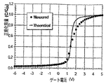
図3A−3CはそれぞれReOx、NOおよびMEOウェーハに対してのnMOSのC−V測定値と理論的C−V曲線を示す。理想的なC−Vは金属−半導体仕事関数差(φMS)と実効固定電荷密度(QF)を考慮に入れて定式化したものである。ReOxとMEOの試料はそれぞれ−1.6×1012cm-2と−6.5×1011cm-2という負の値のQFを持ち、そのことは、測定の掃印中に占有率を変えることのない負電荷のミッドギャップ準位が高濃度に存在することを示すものである。これに反して、NO試料は8.3×1011cm-2という正の値のQFを有する。図3Aに示すように、ReOx試料はEc近くの界面トラップ準位によるフラットバンドから蓄積側へ大きな伸び(ストレッチ・アウト)も示している。NO試料(図3B)は顕著に改良されて、少しだけの伸びに留まり、一方、MEO試料(図3C)のC−V曲線は実際的に理論曲線に一致している。 3A-3C show nMOS CV measurements and theoretical CV curves for ReOx, NO and MEO wafers, respectively. The ideal CV is formulated taking into account the metal-semiconductor work function difference (φ MS ) and the effective fixed charge density (Q F ). The ReOx and MEO samples have negative Q F values of −1.6 × 10 12 cm −2 and −6.5 × 10 11 cm −2 , respectively, which means that the occupancy during measurement sweeping This shows that the mid-gap level of the negative charge that does not change is present at a high concentration. In contrast, the NO sample has a positive Q F of 8.3 × 10 11 cm −2 . As shown in FIG. 3A, the ReOx sample also shows a large stretch (stretch out) from the flat band to the accumulation side due to the interface trap level near E c . The NO sample (FIG. 3B) is significantly improved and stays only slightly stretched, while the CV curve of the MEO sample (FIG. 3C) is practically consistent with the theoretical curve.
図4はMEO、NOおよびReOxウェーハによるMOSFETデバイスに対する、伝導帯から測定したエネルギー準位に対する界面状態密度(DIT)のグラフである。図4に示す室温ACコンダクタンス測定結果は(Ecの下0.2eVまでの)測定可能なエネルギー範囲でNOおよびMEOウェーハとも比較的低い界面準位密度(DIT)を示している。C−V曲線とコンダクタンス測定結果の間のこの明らかな矛盾は、伝導帯エッジに近づくにつれてNOのトラップ分布がMEOの分布よりもより急速に増加するならば解消することになるであろう。 FIG. 4 is a graph of interface state density (D IT ) versus energy level measured from the conduction band for MOSFET devices with MEO, NO and ReOx wafers. The room temperature AC conductance measurement results shown in FIG. 4 show relatively low interface state densities (D IT ) for both NO and MEO wafers in the measurable energy range (up to 0.2 eV under E c ). This apparent discrepancy between the CV curve and the conductance measurement results will be resolved if the NO trap distribution increases more rapidly than the MEO distribution as the conduction band edge is approached.
MEO工程では酸化速度の増大が観測された。しかしながら、許容範囲である600〜900Åの範囲の厚さのゲート酸化膜を作製するためには、この効果は制御できる。MEOの酸化速度は、ウェーハをアルミナに晒すのを制限/制御することによって制御/低減できるものと現在は信じられている。例えば、上記したように、酸化工程中に存在するアルミナは酸化されるべきSiCウェーハの近くに配置されたアルミナ円盤のみに限定された。 In the MEO process, an increase in oxidation rate was observed. However, this effect can be controlled in order to produce a gate oxide film having a thickness in the allowable range of 600 to 900 mm. It is currently believed that the MEO oxidation rate can be controlled / reduced by limiting / controlling the exposure of the wafer to alumina. For example, as described above, the alumina present during the oxidation process was limited to only an alumina disk located near the SiC wafer to be oxidized.
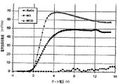
図5はエピタキシャル成長のチャネル(すなわち横型)のMEO、NOおよびReOxウェーハによるMOSFETデバイスに対する室温で測定したチャネル移動度対ゲート電圧のグラフである。MEOとNOウェーハによるMOSFETはどちらも改良されたターン・オン特性を示し、ピークμCHはそれぞれ69と49cm2/Vsである。MEOに対するピークチャネル移動度μCHは非特許文献3にてオラフソン(Olafsson)が報告している値のほぼ50%である。しかしながら、MEOウェーハによる横型MOSFETデバイスに対して色々な温度で測定したチャネル移動度対ゲート電圧のグラフである図6に示すように、MEOデバイスの低電界移動度は150℃の測定温度で160cm2/Vsにまで増加し、これは熱サイクルの後にオラフソンが観測した33%の非可逆的移動度低下と対比すべきものである。(図6に示した高温測定の後で)室温でMEOウェーハによるMOSFETを再測定した結果は、元の室温曲線と同形を示したが、数ボルトシフトした。これは多分可動イオンの動きによるものであろう。
FIG. 5 is a graph of channel mobility versus gate voltage measured at room temperature for MOSFET devices with epitaxially grown channel (ie, lateral) MEO, NO, and ReOx wafers. MOSFET according MEO and NO wafer indicates the turn-on characteristic were both improved peak mu CH are respectively 69 and 49cm 2 / Vs. The peak channel mobility μ CH with respect to MEO is approximately 50% of the value reported by Olafson in
NOウェーハに対するピークチャネル移動度μCHは上記のチュン(Chung)が報告している値の67%増を示す。図7に示すように、ターン・オン特性はイオン注入されたチャンネルを持つMOSFETでは少しだけ減少するが、1×1018cm-3のAlの注入にもかかわらず、MEOとNOに対してそれぞれ48と34cm2/Vsという印象的ともいえるピークチャネル移動度μCHを示す。 The peak channel mobility μ CH for the NO wafer shows a 67% increase over the value reported by Chung above. As shown in FIG. 7, the turn-on characteristics are slightly reduced for MOSFETs with ion-implanted channels, but for MEO and NO, respectively, despite Al implantation of 1 × 10 18 cm −3. The peak channel mobility μ CH which can be said to be impressive of 48 and 34 cm 2 / Vs is shown.
オラフソンはMEO酸化膜の急速熱アニール(RTA)に対する敏感さも報告している。良好な電力用のMOSFETを形成するためには、低抵抗で、電気的に安定で、および/または構造的な完全性のためにオーミック電極を焼結する目的でRTAを用いることが望ましいであろう。MEOの場合は、特定の機構がよくわかってはいないが、その高品質MOS界面が高温RTAに耐え抜いてMOSFET特性に大きな変化を与えることはなかったことを特記しておこう。 Olafson also reports the sensitivity of MEO oxide to rapid thermal annealing (RTA). In order to form a good power MOSFET, it is desirable to use RTA for the purpose of sintering ohmic electrodes for low resistance, electrical stability and / or structural integrity. Let's go. In the case of MEO, the specific mechanism is not well understood, but it should be noted that its high quality MOS interface has survived high temperature RTA and did not significantly change MOSFET characteristics.
MEOウェーハによるMOSFETの特性向上に照らして、MEO酸化膜の研究が行われた。SIMS解析の結果は、たった1018cm-3程度の窒素の濃度が酸化膜中に一様に分布していた。この値は窒素に対するSIMS検出限界に近く、4H−SiCMOS界面を有効に窒素でパッシベーションするために必要な1020cm-3台半ばの濃度に比べると桁違いに低い。これより、窒化はMEOウェーハにおける移動度増大の原因ではないように思われる。図8に示したSIMS解析結果は、特許文献2に記載されているように高濃度の金属不純物(FeとCr)が存在することを確認するものである。注目すべきは鉄は高濃度で存在するだけでなく、高濃度の鉄がSiO2/SiC界面にまでずっと拡がっていることである。
In light of the improvement in MOSFET characteristics with MEO wafers, research on MEO oxide films was conducted. As a result of SIMS analysis, a nitrogen concentration of only about 10 18 cm −3 was uniformly distributed in the oxide film. This value is close to the SIMS detection limit for nitrogen, and is orders of magnitude lower than the concentration in the mid 10 20 cm −3 range necessary for effective passivation of the 4H-SiCMOS interface with nitrogen. Thus, nitridation does not appear to be a cause of increased mobility in MEO wafers. The SIMS analysis result shown in FIG. 8 confirms the presence of high-concentration metal impurities (Fe and Cr) as described in
本発明の実施形態によれば、NOとMEOの工程の両方を用いてよりよい4H−SiCMOS界面が得られた。NOアニールはより高温でよりよい結果が得られることが知られている。しかしながら、以前の工程は石英炉管の温度制限のために1,175℃に制限されていた。本発明のいくつかの実施形態では、化学気相成膜法(CVD)を用いてSiCで被覆されたSiC管内で熱酸化とNOアニールを行うと従来の工程技術の制限を乗り越えて、例えば1,300℃またはそれ以上のプロセス温度を可能にする。その結果、1,175℃NOアニールをしのぐ大きな改良をもたらすことになり、或る場合には、Ecの下0.2eVでのDITに関して50%の低減と、反転層チャネル移動度において67%の増加である49cm2/Vsという値をもたらすことになる。本発明のいくつかの実施形態では、MEO工程では更によい特性をもたらし、室温で69cm2/Vsというピークチャネル移動度が150℃では160cm2/Vsに増大する。1×1018cm-3のAlを注入したチャネルを持つMEOウェーハによるMOSFETでは、移動度はまずまずの値48cm2/Vsである。しかしながら、MEO工程のいくつかの変形では、閾値電圧に影響を与える、SiO2−SiC界面での可動電荷を供給することになる望ましからざる汚染をゲート酸化膜から取り除くことが望ましい。 According to embodiments of the present invention, a better 4H-SiCMOS interface was obtained using both NO and MEO processes. NO annealing is known to give better results at higher temperatures. However, the previous process was limited to 1,175 ° C. due to the temperature limitation of the quartz furnace tube. In some embodiments of the present invention, performing thermal oxidation and NO annealing in a SiC coated SiC tube using chemical vapor deposition (CVD) overcomes the limitations of conventional process technology, for example, 1 , Allowing process temperatures of 300 ° C. or higher. The result is a significant improvement over the 1,175 ° C. NO anneal, in some cases a 50% reduction in D IT at 0.2 eV under E c and 67% in inversion layer channel mobility. % Increase of 49 cm 2 / Vs. In some embodiments of the present invention, the MEO process provides better properties, increasing the peak channel mobility of 69 cm 2 / Vs at room temperature to 160 cm 2 / Vs at 150 ° C. In a MOSFET using an MEO wafer having a channel implanted with Al of 1 × 10 18 cm −3 , the mobility is a reasonable value of 48 cm 2 / Vs. However, in some variations of the MEO process, it affects the threshold voltage, it is desirable to remove the undesired contamination would supply mobile charge in the SiO 2 -SiC interface from the gate oxide film.
(1,300℃で、NO中でのアニール工程を含む)本発明の実施形態により形成され、1×1018cm-3のチャネルドーピングを有するイオン注入したチャンネルを持つMOSFETデバイスは35cm2/Vsのチャネル移動度μCHを示した。イオン注入したチャネルを持つデバイスのチャネル移動度は注入損傷のためにエピタキシャルチャンネルデバイスよりは低くなるであろうと予想される。 A MOSFET device having an ion-implanted channel formed according to an embodiment of the present invention (including an annealing step in NO at 1,300 ° C.) having a channel doping of 1 × 10 18 cm −3 is 35 cm 2 / Vs. channel mobility exhibited mu CH. It is expected that the channel mobility of devices with ion implanted channels will be lower than epitaxial channel devices due to implantation damage.
図面と明細書において本発明の典型的な実施形態が開示された。専門的な用語が用いられたけれども、それらは一般的で記述目的のためだけに用いられたものであり、限定しようとするために用いられたものではない。本発明の技術範囲は請求項に記述されているものである。 In the drawings and specification, there have been disclosed exemplary embodiments of the invention. Although technical terms were used, they were general and used only for descriptive purposes, not for limiting purposes. The technical scope of the present invention is described in the claims.
添付図面は、本発明のよりよき理解を提供するために含まれているものであり、本申請書の1部に取り込まれて構成されているが、本発明のある実施形態を示すものである。 The accompanying drawings are included to provide a better understanding of the invention, and are incorporated in and constitute a part of this application, but illustrate certain embodiments of the invention. .
Claims (30)
炭化珪素層上に酸化膜層を熱的に成長させる工程と、
NOを含む雰囲気中で1,175℃より高い温度で前記酸化膜層をアニールする工程と、
を含む方法。 A method of forming an oxide film layer on silicon carbide,
Thermally growing an oxide film layer on the silicon carbide layer;
Annealing the oxide layer at a temperature higher than 1,175 ° C. in an atmosphere containing NO;
Including methods.
前記炭化珪素層上に初期酸化膜層をドライ酸素雰囲気中で約1200℃の温度にて熱的に成長させる工程と、
前記初期酸化膜層をウェット酸素雰囲気中で約950℃の温度で再酸化する工程と、
を含むことを特徴とする、請求項1に記載の方法。 The step of thermally growing the oxide film layer includes:
Thermally growing an initial oxide film layer on the silicon carbide layer in a dry oxygen atmosphere at a temperature of about 1200 ° C .;
Reoxidizing the initial oxide layer at a temperature of about 950 ° C. in a wet oxygen atmosphere;
The method of claim 1, comprising:
炭化珪素の層上に酸化膜層を熱的に成長させる工程と、
1175℃より高い温度で、NOを含む雰囲気中で前記酸化膜層をアニールする工程と、
前記酸化膜層上にゲート電極を形成する工程と、
を含むことを特徴とする方法。 A method of forming a silicon carbide MOS structure comprising:
Thermally growing an oxide film layer on the silicon carbide layer;
Annealing the oxide film layer in an atmosphere containing NO at a temperature higher than 1175 ° C .;
Forming a gate electrode on the oxide layer;
A method comprising the steps of:
前記炭化珪素層上に初期酸化膜層をドライ酸素雰囲気中で約1200℃の温度にて熱的に成長させる工程と、
前記初期酸化膜層をウェット酸素雰囲気中で約950℃の温度で再酸化する工程と、
を含むことを特徴とする、請求項13に記載の方法。 The step of thermally growing the oxide film layer includes:
Thermally growing an initial oxide film layer on the silicon carbide layer in a dry oxygen atmosphere at a temperature of about 1200 ° C .;
Reoxidizing the initial oxide layer at a temperature of about 950 ° C. in a wet oxygen atmosphere;
The method of claim 13, comprising:
前記p型炭化珪素領域内にn型領域を形成する工程を更に含んで、
前記酸化膜層を熱的に成長させる工程は前記p型炭化珪素領域上と前記n型領域上の少なくとも1部分とに前記酸化膜層を熱的に成長させる工程を含むことを特徴とする、請求項25に記載の方法。 The silicon carbide layer includes a region of p-type silicon carbide, the method comprising:
Further comprising forming an n-type region in the p-type silicon carbide region,
The step of thermally growing the oxide film layer includes the step of thermally growing the oxide film layer on at least a part on the p-type silicon carbide region and the n-type region, 26. The method of claim 25.
前記n型領域は、n型ソース領域を含むことを特徴とする方法であって、
前記方法は、前記p型エピタキシャル層内に前記n型ソース領域からは隔たっているn型ドレイン領域であって、前記ソース領域と前記ドレイン領域との間にチャネル領域を区画するところのn型ドレイン領域を形成する工程を更に含み、
前記酸化膜層を熱的に成長させる工程は、前記酸化膜層を前記チャネル領域上に熱的に成長させる工程を含むことを特徴とする、請求項26に記載の方法。 The p-type silicon carbide region includes a p-type epitaxial layer,
The n-type region includes an n-type source region,
In the method, the n-type drain region is separated from the n-type source region in the p-type epitaxial layer, and a channel region is defined between the source region and the drain region. Further comprising forming a region,
27. The method of claim 26, wherein the step of thermally growing the oxide layer includes the step of thermally growing the oxide layer on the channel region.
前記n型ソース領域と前記n型 ドレイン領域上の前記オーム性電極を少なくとも約500℃の温度でアニールする工程と、
を更に含み、前記チャネル領域が、前記オーム性電極のアニール後に室温で少なくとも約40cm2/Vsのチャンネル移動度を有することを特徴とする、請求項27に記載の方法。 Forming an ohmic electrode on the n-type source region and the n-type drain region, and annealing the ohmic electrode on the n-type source region and the n-type drain region at a temperature of at least about 500 ° C .; ,
28. The method of claim 27, wherein the channel region has a channel mobility of at least about 40 cm < 2 > / Vs at room temperature after annealing of the ohmic electrode.
前記n型領域は、n型ソース領域を含むことを特徴とする方法であって、
前記方法は、n型JFET領域の近傍に、前記構造の表面から前記p型井戸領域の下に配置されたドリフト領域まで伸びる、イオン注入されたp型井戸領域を形成する工程を更に含み、
前記酸化膜層を熱的に成長させる工程は、前記p型井戸領域内で、前記ソース領域から前記JFET領域の間に伸びているチャネル領域上に前記酸化膜層を熱的に成長させる工程を含むことを特徴とする、請求項26に記載の方法。 The p-type silicon carbide region includes an ion-implanted p-type well region,
The n-type region includes an n-type source region,
The method further includes forming an ion-implanted p-type well region in the vicinity of the n-type JFET region that extends from the surface of the structure to a drift region disposed below the p-type well region;
The step of thermally growing the oxide layer includes the step of thermally growing the oxide layer on a channel region extending between the source region and the JFET region in the p-type well region. 27. The method of claim 26, comprising:
前記n型ソース領域上の前記オーム性電極を少なくとも約500℃の温度でアニールする工程と、
を更に含み、前記チャネル領域が、前記オーム性電極のアニール後に室温で少なくとも約35cm2/Vsのチャンネル移動度を持つことを特徴とする、請求項27に記載の方法。 Forming an ohmic electrode on the n-type source region;
Annealing the ohmic electrode on the n-type source region at a temperature of at least about 500 ° C .;
28. The method of claim 27, further comprising: the channel region having a channel mobility of at least about 35 cm 2 / Vs at room temperature after annealing of the ohmic electrode.
Applications Claiming Priority (5)
| Application Number | Priority Date | Filing Date | Title |
|---|---|---|---|
| US71795305P | 2005-09-16 | 2005-09-16 | |
| US60/717,953 | 2005-09-16 | ||
| US11/486,752 US7727904B2 (en) | 2005-09-16 | 2006-07-14 | Methods of forming SiC MOSFETs with high inversion layer mobility |
| US11/486,752 | 2006-07-14 | ||
| PCT/US2006/035285 WO2007035304A1 (en) | 2005-09-16 | 2006-09-12 | Methods of forming sic mosfets with high inversion layer mobility |
Publications (3)
| Publication Number | Publication Date |
|---|---|
| JP2009509338A true JP2009509338A (en) | 2009-03-05 |
| JP2009509338A5 JP2009509338A5 (en) | 2009-11-05 |
| JP5603008B2 JP5603008B2 (en) | 2014-10-08 |
Family
ID=37561035
Family Applications (1)
| Application Number | Title | Priority Date | Filing Date |
|---|---|---|---|
| JP2008531214A Active JP5603008B2 (en) | 2005-09-16 | 2006-09-12 | Method for forming SiCMOSFET having large inversion layer mobility |
Country Status (6)
| Country | Link |
|---|---|
| US (2) | US7727904B2 (en) |
| EP (1) | EP1938363B1 (en) |
| JP (1) | JP5603008B2 (en) |
| CN (1) | CN101283439B (en) |
| TW (1) | TW200731406A (en) |
| WO (1) | WO2007035304A1 (en) |
Cited By (3)
| Publication number | Priority date | Publication date | Assignee | Title |
|---|---|---|---|---|
| WO2014024568A1 (en) * | 2012-08-07 | 2014-02-13 | 住友電気工業株式会社 | Silicon-carbide semiconductor device and manufacturing method therefor |
| WO2014046073A1 (en) * | 2012-09-24 | 2014-03-27 | 住友電気工業株式会社 | Silicon carbide semiconductor device and fabrication method for same |
| US9935170B2 (en) | 2014-11-06 | 2018-04-03 | Mitsubishi Electric Corporation | Silicon carbide semiconductor device and method for manufacturing same |
Families Citing this family (28)
| Publication number | Priority date | Publication date | Assignee | Title |
|---|---|---|---|---|
| JP5183913B2 (en) * | 2006-11-24 | 2013-04-17 | 住友電工デバイス・イノベーション株式会社 | Manufacturing method of semiconductor device |
| JP5728153B2 (en) * | 2008-09-26 | 2015-06-03 | 株式会社東芝 | Manufacturing method of semiconductor device |
| US8536582B2 (en) * | 2008-12-01 | 2013-09-17 | Cree, Inc. | Stable power devices on low-angle off-cut silicon carbide crystals |
| JP5699628B2 (en) * | 2010-07-26 | 2015-04-15 | 住友電気工業株式会社 | Semiconductor device |
| JP2012064873A (en) * | 2010-09-17 | 2012-03-29 | Rohm Co Ltd | Semiconductor device and method of manufacturing the same |
| US8890169B2 (en) * | 2010-11-08 | 2014-11-18 | Hitachi, Ltd. | Semiconductor device |
| CN102169104A (en) * | 2010-12-22 | 2011-08-31 | 重庆邮电大学 | SiC-based MOSFET (metal-oxide -semiconductor field effect transistor) oxysensible sensor for automobile engine |
| CN102184964B (en) * | 2011-05-12 | 2013-03-20 | 西安电子科技大学 | N-channel accumulative SiC IEMOSFET (Implantation and Epitaxial Metal-Oxide-Semiconductor Field Effect Transistor) device and manufacturing method thereof |
| US9396946B2 (en) * | 2011-06-27 | 2016-07-19 | Cree, Inc. | Wet chemistry processes for fabricating a semiconductor device with increased channel mobility |
| US9984894B2 (en) | 2011-08-03 | 2018-05-29 | Cree, Inc. | Forming SiC MOSFETs with high channel mobility by treating the oxide interface with cesium ions |
| US9257283B2 (en) | 2012-08-06 | 2016-02-09 | General Electric Company | Device having reduced bias temperature instability (BTI) |
| JP2014154667A (en) * | 2013-02-07 | 2014-08-25 | Sumitomo Electric Ind Ltd | Semiconductor device |
| JP6189131B2 (en) * | 2013-08-01 | 2017-08-30 | 株式会社東芝 | Semiconductor device and manufacturing method thereof |
| US9991376B2 (en) | 2013-09-20 | 2018-06-05 | Monolith Semiconductor Inc. | High voltage MOSFET devices and methods of making the devices |
| US9214572B2 (en) * | 2013-09-20 | 2015-12-15 | Monolith Semiconductor Inc. | High voltage MOSFET devices and methods of making the devices |
| JP6158153B2 (en) * | 2014-09-19 | 2017-07-05 | 株式会社東芝 | Semiconductor device and manufacturing method thereof |
| CN104658903A (en) * | 2015-01-30 | 2015-05-27 | 株洲南车时代电气股份有限公司 | Method for preparing SiC MOSFET gate oxide layer |
| JP6584966B2 (en) * | 2016-01-12 | 2019-10-02 | 株式会社東芝 | Semiconductor device, semiconductor device manufacturing method, inverter circuit, drive device, vehicle, and elevator |
| US10020243B2 (en) | 2016-03-08 | 2018-07-10 | Toyota Motor Engineering & Manufacturing North America, Inc. | Power electronics assemblies having a wide bandgap semiconductor device and an integrated fluid channel system |
| CN105957898B (en) * | 2016-07-05 | 2019-09-24 | 安徽工业大学 | A kind of low-power consumption 4H-SiC voltage-controlled type power semiconductor and preparation method thereof |
| US10121729B2 (en) * | 2016-07-25 | 2018-11-06 | Toyota Motor Engineering & Manufacturing North America, Inc. | Power electronics assemblies having a semiconductor device with metallized embedded cooling channels |
| CN107393814B (en) * | 2017-08-10 | 2020-03-24 | 中国科学院上海微系统与信息技术研究所 | MOS power device and preparation method thereof |
| CN111725330A (en) * | 2019-03-21 | 2020-09-29 | 中国科学院微电子研究所 | Preparation method of silicon carbide MOS capacitor gate oxide layer |
| CN110783173A (en) * | 2019-10-22 | 2020-02-11 | 中国电子科技集团公司第五十五研究所 | Method for manufacturing gate oxide layer on silicon carbide material |
| JP7259139B2 (en) | 2020-03-17 | 2023-04-17 | ヒタチ・エナジー・スウィツァーランド・アクチェンゲゼルシャフト | Insulated gate structure, wide bandgap material power device with the same, and manufacturing method thereof |
| CN111403280A (en) * | 2020-03-31 | 2020-07-10 | 中国科学院微电子研究所 | Silicon carbide MOS capacitor device and manufacturing method thereof |
| JP7271484B2 (en) * | 2020-09-15 | 2023-05-11 | 株式会社東芝 | Semiconductor device, method for manufacturing semiconductor device, inverter circuit, drive device, vehicle, and elevator |
| CN113035709B (en) * | 2021-03-01 | 2022-11-08 | 同辉电子科技股份有限公司 | Method for improving interface characteristics of SiC device |
Citations (8)
| Publication number | Priority date | Publication date | Assignee | Title |
|---|---|---|---|---|
| JPH09235163A (en) * | 1995-12-26 | 1997-09-09 | Tokai Carbon Co Ltd | Heat-treatment jig and production thereof |
| JP2002274983A (en) * | 2001-03-12 | 2002-09-25 | Tokai Konetsu Kogyo Co Ltd | Member for semiconductor manufacturing apparatus coated with sic film and method of manufacturing the same |
| JP2003086792A (en) * | 2001-09-10 | 2003-03-20 | National Institute Of Advanced Industrial & Technology | Manufacturing method for semiconductor device |
| JP2004511101A (en) * | 2000-10-03 | 2004-04-08 | クリー インコーポレイテッド | Method for producing oxide layer on silicon carbide layer using N2O |
| JP2004281672A (en) * | 2003-03-14 | 2004-10-07 | Hitachi Kokusai Electric Inc | Heat treatment equipment and method for manufacturing substrate |
| JP2004533727A (en) * | 2001-06-28 | 2004-11-04 | コーニンクレッカ フィリップス エレクトロニクス エヌ ヴィ | Method for increasing mobility of inversion layer of silicon carbide metal oxide semiconductor field effect transistor |
| JP2005109396A (en) * | 2003-10-02 | 2005-04-21 | National Institute Of Advanced Industrial & Technology | Manufacturing method of semiconductor device, and insulating film forming system |
| JP2005166930A (en) * | 2003-12-02 | 2005-06-23 | Matsushita Electric Ind Co Ltd | Sic-misfet and its manufacturing method |
Family Cites Families (85)
| Publication number | Priority date | Publication date | Assignee | Title |
|---|---|---|---|---|
| US3924024A (en) | 1973-04-02 | 1975-12-02 | Ncr Co | Process for fabricating MNOS non-volatile memories |
| CA1075437A (en) | 1975-07-28 | 1980-04-15 | Malcolm E. Washburn | Porous silicon oxynitride refractory shapes |
| US4466172A (en) | 1979-01-08 | 1984-08-21 | American Microsystems, Inc. | Method for fabricating MOS device with self-aligned contacts |
| JPS648633A (en) | 1987-07-01 | 1989-01-12 | Hitachi Ltd | Semiconductor device |
| JPS648633U (en) | 1987-09-16 | 1989-01-18 | ||
| US4875083A (en) | 1987-10-26 | 1989-10-17 | North Carolina State University | Metal-insulator-semiconductor capacitor formed on silicon carbide |
| US5030600A (en) | 1988-10-06 | 1991-07-09 | Benchmark Structural Ceramics Corp. | Novel sialon composition |
| JPH0766971B2 (en) | 1989-06-07 | 1995-07-19 | シャープ株式会社 | Silicon carbide semiconductor device |
| JPH03157974A (en) | 1989-11-15 | 1991-07-05 | Nec Corp | Vertical type field effect transistor |
| JPH0718056B2 (en) | 1990-04-27 | 1995-03-01 | 株式会社コロイドリサーチ | Method for producing oxynitride ceramic fiber |
| JP2542448B2 (en) | 1990-05-24 | 1996-10-09 | シャープ株式会社 | Field effect transistor and method of manufacturing the same |
| US5170455A (en) | 1991-10-30 | 1992-12-08 | At&T Bell Laboratories | Optical connective device |
| US5459107A (en) | 1992-06-05 | 1995-10-17 | Cree Research, Inc. | Method of obtaining high quality silicon dioxide passivation on silicon carbide and resulting passivated structures |
| US6344663B1 (en) | 1992-06-05 | 2002-02-05 | Cree, Inc. | Silicon carbide CMOS devices |
| US5726463A (en) | 1992-08-07 | 1998-03-10 | General Electric Company | Silicon carbide MOSFET having self-aligned gate structure |
| US5587870A (en) | 1992-09-17 | 1996-12-24 | Research Foundation Of State University Of New York | Nanocrystalline layer thin film capacitors |
| US5506421A (en) | 1992-11-24 | 1996-04-09 | Cree Research, Inc. | Power MOSFET in silicon carbide |
| KR100305123B1 (en) | 1992-12-11 | 2001-11-22 | 비센트 비.인그라시아, 알크 엠 아헨 | Static Random Access Memory Cells and Semiconductor Devices Containing These |
| JP3494304B2 (en) | 1993-02-01 | 2004-02-09 | 富士ゼロックス株式会社 | Method for manufacturing thin film semiconductor device |
| JP2531572B2 (en) | 1993-08-09 | 1996-09-04 | 東芝セラミックス株式会社 | Method for oxynitriding quartz glass and method for surface treatment |
| US5479316A (en) | 1993-08-24 | 1995-12-26 | Analog Devices, Inc. | Integrated circuit metal-oxide-metal capacitor and method of making same |
| US5510630A (en) | 1993-10-18 | 1996-04-23 | Westinghouse Electric Corporation | Non-volatile random access memory cell constructed of silicon carbide |
| JPH07221038A (en) | 1994-02-04 | 1995-08-18 | Matsushita Electron Corp | Heat treating furnace |
| JP3521246B2 (en) | 1995-03-27 | 2004-04-19 | 沖電気工業株式会社 | Field effect transistor and method of manufacturing the same |
| JPH11261061A (en) | 1998-03-11 | 1999-09-24 | Denso Corp | Silicon carbide semiconductor device and its manufacture |
| JP4001960B2 (en) | 1995-11-03 | 2007-10-31 | フリースケール セミコンダクター インコーポレイテッド | Method for manufacturing a semiconductor device having a nitrided oxide dielectric layer |
| US5972801A (en) | 1995-11-08 | 1999-10-26 | Cree Research, Inc. | Process for reducing defects in oxide layers on silicon carbide |
| US6136728A (en) | 1996-01-05 | 2000-10-24 | Yale University | Water vapor annealing process |
| JPH09205202A (en) | 1996-01-26 | 1997-08-05 | Matsushita Electric Works Ltd | Semiconductor device |
| US5877045A (en) | 1996-04-10 | 1999-03-02 | Lsi Logic Corporation | Method of forming a planar surface during multi-layer interconnect formation by a laser-assisted dielectric deposition |
| US5763905A (en) | 1996-07-09 | 1998-06-09 | Abb Research Ltd. | Semiconductor device having a passivation layer |
| US6002159A (en) | 1996-07-16 | 1999-12-14 | Abb Research Ltd. | SiC semiconductor device comprising a pn junction with a voltage absorbing edge |
| US5939763A (en) | 1996-09-05 | 1999-08-17 | Advanced Micro Devices, Inc. | Ultrathin oxynitride structure and process for VLSI applications |
| US6130160A (en) * | 1996-10-02 | 2000-10-10 | Micron Technology, Inc. | Methods, complexes and system for forming metal-containing films |
| US6091077A (en) | 1996-10-22 | 2000-07-18 | Matsushita Electric Industrial Co., Ltd. | MIS SOI semiconductor device with RTD and/or HET |
| US6028012A (en) | 1996-12-04 | 2000-02-22 | Yale University | Process for forming a gate-quality insulating layer on a silicon carbide substrate |
| US5837572A (en) | 1997-01-10 | 1998-11-17 | Advanced Micro Devices, Inc. | CMOS integrated circuit formed by using removable spacers to produce asymmetrical NMOS junctions before asymmetrical PMOS junctions for optimizing thermal diffusivity of dopants implanted therein |
| JP3206727B2 (en) | 1997-02-20 | 2001-09-10 | 富士電機株式会社 | Silicon carbide vertical MOSFET and method of manufacturing the same |
| DE19809554B4 (en) | 1997-03-05 | 2008-04-03 | Denso Corp., Kariya | silicon carbide semiconductor device |
| US6063698A (en) | 1997-06-30 | 2000-05-16 | Motorola, Inc. | Method for manufacturing a high dielectric constant gate oxide for use in semiconductor integrated circuits |
| JP3180895B2 (en) | 1997-08-18 | 2001-06-25 | 富士電機株式会社 | Method for manufacturing silicon carbide semiconductor device |
| EP1010204A1 (en) | 1997-08-20 | 2000-06-21 | Siemens Aktiengesellschaft | Semiconductor structure comprising an alpha silicon carbide zone, and use of said semiconductor structure |
| US6239463B1 (en) | 1997-08-28 | 2001-05-29 | Siliconix Incorporated | Low resistance power MOSFET or other device containing silicon-germanium layer |
| SE9704150D0 (en) | 1997-11-13 | 1997-11-13 | Abb Research Ltd | Semiconductor device of SiC with insulating layer a refractory metal nitride layer |
| JPH11191559A (en) | 1997-12-26 | 1999-07-13 | Matsushita Electric Works Ltd | Manufacture of mosfet |
| JPH11251592A (en) | 1998-01-05 | 1999-09-07 | Denso Corp | Carbon silicon semiconductor device |
| JP3216804B2 (en) | 1998-01-06 | 2001-10-09 | 富士電機株式会社 | Manufacturing method of silicon carbide vertical FET and silicon carbide vertical FET |
| JPH11266017A (en) | 1998-01-14 | 1999-09-28 | Denso Corp | Silicon carbide semiconductor device and manufacture thereof |
| JPH11238742A (en) | 1998-02-23 | 1999-08-31 | Denso Corp | Manufacture of silicon carbide semiconductor device |
| JP3893725B2 (en) | 1998-03-25 | 2007-03-14 | 株式会社デンソー | Method for manufacturing silicon carbide semiconductor device |
| US6627539B1 (en) | 1998-05-29 | 2003-09-30 | Newport Fab, Llc | Method of forming dual-damascene interconnect structures employing low-k dielectric materials |
| US6107142A (en) | 1998-06-08 | 2000-08-22 | Cree Research, Inc. | Self-aligned methods of fabricating silicon carbide power devices by implantation and lateral diffusion |
| US6100169A (en) | 1998-06-08 | 2000-08-08 | Cree, Inc. | Methods of fabricating silicon carbide power devices by controlled annealing |
| JP4123636B2 (en) | 1998-06-22 | 2008-07-23 | 株式会社デンソー | Silicon carbide semiconductor device and manufacturing method thereof |
| US5960289A (en) | 1998-06-22 | 1999-09-28 | Motorola, Inc. | Method for making a dual-thickness gate oxide layer using a nitride/oxide composite region |
| JP3959856B2 (en) | 1998-07-31 | 2007-08-15 | 株式会社デンソー | Silicon carbide semiconductor device and manufacturing method thereof |
| JP2000106371A (en) | 1998-07-31 | 2000-04-11 | Denso Corp | Fabrication of silicon carbide semiconductor device |
| US6221700B1 (en) | 1998-07-31 | 2001-04-24 | Denso Corporation | Method of manufacturing silicon carbide semiconductor device with high activation rate of impurities |
| US6246076B1 (en) | 1998-08-28 | 2001-06-12 | Cree, Inc. | Layered dielectric on silicon carbide semiconductor structures |
| JP2000133633A (en) | 1998-09-09 | 2000-05-12 | Texas Instr Inc <Ti> | Etching of material using hard mask and plasma activating etchant |
| US6048766A (en) | 1998-10-14 | 2000-04-11 | Advanced Micro Devices | Flash memory device having high permittivity stacked dielectric and fabrication thereof |
| US6204203B1 (en) | 1998-10-14 | 2001-03-20 | Applied Materials, Inc. | Post deposition treatment of dielectric films for interface control |
| JP2000201050A (en) | 1998-11-02 | 2000-07-18 | Ngk Insulators Ltd | Substrate for surface acoustic wave device and manufacture of the same |
| US6190973B1 (en) | 1998-12-18 | 2001-02-20 | Zilog Inc. | Method of fabricating a high quality thin oxide |
| US6228720B1 (en) | 1999-02-23 | 2001-05-08 | Matsushita Electric Industrial Co., Ltd. | Method for making insulated-gate semiconductor element |
| JP3443589B2 (en) | 1999-03-01 | 2003-09-02 | 独立行政法人産業技術総合研究所 | Method for manufacturing semiconductor device |
| US6261976B1 (en) | 1999-03-18 | 2001-07-17 | Chartered Semiconductor Manufacturing Ltd. | Method of forming low pressure silicon oxynitride dielectrics having high reliability |
| US6238967B1 (en) | 1999-04-12 | 2001-05-29 | Motorola, Inc. | Method of forming embedded DRAM structure |
| JP2000349081A (en) | 1999-06-07 | 2000-12-15 | Sony Corp | Method for formation of oxide film |
| JP4531164B2 (en) | 1999-08-23 | 2010-08-25 | 株式会社半導体エネルギー研究所 | Method for manufacturing semiconductor device |
| JP4192353B2 (en) | 1999-09-21 | 2008-12-10 | 株式会社デンソー | Silicon carbide semiconductor device and manufacturing method thereof |
| US6524877B1 (en) | 1999-10-26 | 2003-02-25 | Semiconductor Energy Laboratory Co., Ltd. | Semiconductor device, and method of fabricating the same |
| US7148153B2 (en) * | 2000-06-20 | 2006-12-12 | Agere Systems Inc. | Process for oxide fabrication using oxidation steps below and above a threshold temperature |
| DE10036208B4 (en) | 2000-07-25 | 2007-04-19 | Siced Electronics Development Gmbh & Co. Kg | Semiconductor structure with buried island area and contact area |
| US6956238B2 (en) | 2000-10-03 | 2005-10-18 | Cree, Inc. | Silicon carbide power metal-oxide semiconductor field effect transistors having a shorting channel and methods of fabricating silicon carbide metal-oxide semiconductor field effect transistors having a shorting channel |
| US7067176B2 (en) | 2000-10-03 | 2006-06-27 | Cree, Inc. | Method of fabricating an oxide layer on a silicon carbide layer utilizing an anneal in a hydrogen environment |
| US6610366B2 (en) * | 2000-10-03 | 2003-08-26 | Cree, Inc. | Method of N2O annealing an oxide layer on a silicon carbide layer |
| US6767843B2 (en) | 2000-10-03 | 2004-07-27 | Cree, Inc. | Method of N2O growth of an oxide layer on a silicon carbide layer |
| US6593620B1 (en) | 2000-10-06 | 2003-07-15 | General Semiconductor, Inc. | Trench DMOS transistor with embedded trench schottky rectifier |
| US6600138B2 (en) | 2001-04-17 | 2003-07-29 | Mattson Technology, Inc. | Rapid thermal processing system for integrated circuits |
| US6707011B2 (en) | 2001-04-17 | 2004-03-16 | Mattson Technology, Inc. | Rapid thermal processing system for integrated circuits |
| US6632747B2 (en) | 2001-06-20 | 2003-10-14 | Texas Instruments Incorporated | Method of ammonia annealing of ultra-thin silicon dioxide layers for uniform nitrogen profile |
| EP1271636A1 (en) * | 2001-06-22 | 2003-01-02 | Infineon Technologies AG | Thermal oxidation process control by controlling oxidation agent partial pressure |
| US7022378B2 (en) | 2002-08-30 | 2006-04-04 | Cree, Inc. | Nitrogen passivation of interface states in SiO2/SiC structures |
| US7709403B2 (en) | 2003-10-09 | 2010-05-04 | Panasonic Corporation | Silicon carbide-oxide layered structure, production method thereof, and semiconductor device |
-
2006
- 2006-07-14 US US11/486,752 patent/US7727904B2/en active Active
- 2006-09-12 WO PCT/US2006/035285 patent/WO2007035304A1/en active Application Filing
- 2006-09-12 JP JP2008531214A patent/JP5603008B2/en active Active
- 2006-09-12 CN CN2006800341315A patent/CN101283439B/en active Active
- 2006-09-12 EP EP06814442.7A patent/EP1938363B1/en active Active
- 2006-09-15 TW TW095134218A patent/TW200731406A/en unknown
-
2010
- 2010-05-10 US US12/776,831 patent/US8536066B2/en active Active
Patent Citations (8)
| Publication number | Priority date | Publication date | Assignee | Title |
|---|---|---|---|---|
| JPH09235163A (en) * | 1995-12-26 | 1997-09-09 | Tokai Carbon Co Ltd | Heat-treatment jig and production thereof |
| JP2004511101A (en) * | 2000-10-03 | 2004-04-08 | クリー インコーポレイテッド | Method for producing oxide layer on silicon carbide layer using N2O |
| JP2002274983A (en) * | 2001-03-12 | 2002-09-25 | Tokai Konetsu Kogyo Co Ltd | Member for semiconductor manufacturing apparatus coated with sic film and method of manufacturing the same |
| JP2004533727A (en) * | 2001-06-28 | 2004-11-04 | コーニンクレッカ フィリップス エレクトロニクス エヌ ヴィ | Method for increasing mobility of inversion layer of silicon carbide metal oxide semiconductor field effect transistor |
| JP2003086792A (en) * | 2001-09-10 | 2003-03-20 | National Institute Of Advanced Industrial & Technology | Manufacturing method for semiconductor device |
| JP2004281672A (en) * | 2003-03-14 | 2004-10-07 | Hitachi Kokusai Electric Inc | Heat treatment equipment and method for manufacturing substrate |
| JP2005109396A (en) * | 2003-10-02 | 2005-04-21 | National Institute Of Advanced Industrial & Technology | Manufacturing method of semiconductor device, and insulating film forming system |
| JP2005166930A (en) * | 2003-12-02 | 2005-06-23 | Matsushita Electric Ind Co Ltd | Sic-misfet and its manufacturing method |
Non-Patent Citations (1)
| Title |
|---|
| JPN7013002921; G. Y. Chung et al.: 'Effect of nitric oxide annealing on the interface trap densities near the band edges in the 4H polyt' APPLIED PHYSICS LETTERS Vol. 76, No. 13, 20000327, 1713-1715 |
Cited By (7)
| Publication number | Priority date | Publication date | Assignee | Title |
|---|---|---|---|---|
| WO2014024568A1 (en) * | 2012-08-07 | 2014-02-13 | 住友電気工業株式会社 | Silicon-carbide semiconductor device and manufacturing method therefor |
| JP2014036032A (en) * | 2012-08-07 | 2014-02-24 | Sumitomo Electric Ind Ltd | Silicon carbide semiconductor device and method of manufacturing the same |
| US9147731B2 (en) | 2012-08-07 | 2015-09-29 | Sumitomo Electric Industries, Ltd. | Silicon carbide semiconductor device and method for manufacturing same |
| US9425263B2 (en) | 2012-08-07 | 2016-08-23 | Sumitomo Electric Industries, Ltd. | Silicon carbide semiconductor device and method for manufacturing same |
| US9627488B2 (en) | 2012-08-07 | 2017-04-18 | Sumitomo Electric Industries, Ltd. | Silicon carbide semiconductor device and method for manufacturing same |
| WO2014046073A1 (en) * | 2012-09-24 | 2014-03-27 | 住友電気工業株式会社 | Silicon carbide semiconductor device and fabrication method for same |
| US9935170B2 (en) | 2014-11-06 | 2018-04-03 | Mitsubishi Electric Corporation | Silicon carbide semiconductor device and method for manufacturing same |
Also Published As
| Publication number | Publication date |
|---|---|
| CN101283439B (en) | 2010-12-08 |
| EP1938363A1 (en) | 2008-07-02 |
| US8536066B2 (en) | 2013-09-17 |
| US20080233285A1 (en) | 2008-09-25 |
| EP1938363B1 (en) | 2014-06-25 |
| US20100221924A1 (en) | 2010-09-02 |
| WO2007035304A1 (en) | 2007-03-29 |
| US7727904B2 (en) | 2010-06-01 |
| TW200731406A (en) | 2007-08-16 |
| CN101283439A (en) | 2008-10-08 |
| JP5603008B2 (en) | 2014-10-08 |
Similar Documents
| Publication | Publication Date | Title |
|---|---|---|
| JP5603008B2 (en) | Method for forming SiCMOSFET having large inversion layer mobility | |
| JP5306193B2 (en) | Silicon carbide switching device including p-type channel and method of forming the same | |
| US7381992B2 (en) | Silicon carbide power devices with self-aligned source and well regions | |
| JP6052911B2 (en) | Formation of SiC MOSFET with high channel mobility by treating oxide interface with cesium ions | |
| US9012984B2 (en) | Field effect transistor devices with regrown p-layers | |
| US6559068B2 (en) | Method for improving inversion layer mobility in a silicon carbide metal-oxide semiconductor field-effect transistor | |
| JP4549167B2 (en) | Method for manufacturing silicon carbide semiconductor device | |
| JP2014222735A (en) | Semiconductor device and manufacturing method thereof | |
| JP2003243653A (en) | Method for manufacturing silicon carbide semiconductor device | |
| US8536583B2 (en) | MOSFET and method for manufacturing MOSFET | |
| JP3941641B2 (en) | Silicon carbide semiconductor device manufacturing method and silicon carbide semiconductor device manufactured by the manufacturing method | |
| EP1908118B1 (en) | Method for producing a semiconductor device | |
| Williams et al. | Nitrogen passivation of the interface states near the conduction band edge in 4H-silicon carbide | |
| JP2024032679A (en) | How to manufacture ohmic contacts for electronic devices with thermal budget optimization |
Legal Events
| Date | Code | Title | Description |
|---|---|---|---|
| A521 | Request for written amendment filed |
Free format text: JAPANESE INTERMEDIATE CODE: A523 Effective date: 20090914 |
|
| A621 | Written request for application examination |
Free format text: JAPANESE INTERMEDIATE CODE: A621 Effective date: 20090914 |
|
| RD04 | Notification of resignation of power of attorney |
Free format text: JAPANESE INTERMEDIATE CODE: A7424 Effective date: 20110223 |
|
| RD02 | Notification of acceptance of power of attorney |
Free format text: JAPANESE INTERMEDIATE CODE: A7422 Effective date: 20110209 |
|
| A131 | Notification of reasons for refusal |
Free format text: JAPANESE INTERMEDIATE CODE: A131 Effective date: 20120807 |
|
| A977 | Report on retrieval |
Free format text: JAPANESE INTERMEDIATE CODE: A971007 Effective date: 20120809 |
|
| A601 | Written request for extension of time |
Free format text: JAPANESE INTERMEDIATE CODE: A601 Effective date: 20121107 |
|
| A602 | Written permission of extension of time |
Free format text: JAPANESE INTERMEDIATE CODE: A602 Effective date: 20121114 |
|
| A601 | Written request for extension of time |
Free format text: JAPANESE INTERMEDIATE CODE: A601 Effective date: 20121207 |
|
| A602 | Written permission of extension of time |
Free format text: JAPANESE INTERMEDIATE CODE: A602 Effective date: 20121214 |
|
| A601 | Written request for extension of time |
Free format text: JAPANESE INTERMEDIATE CODE: A601 Effective date: 20130107 |
|
| A602 | Written permission of extension of time |
Free format text: JAPANESE INTERMEDIATE CODE: A602 Effective date: 20130115 |
|
| A521 | Request for written amendment filed |
Free format text: JAPANESE INTERMEDIATE CODE: A523 Effective date: 20130207 |
|
| A02 | Decision of refusal |
Free format text: JAPANESE INTERMEDIATE CODE: A02 Effective date: 20130308 |
|
| A521 | Request for written amendment filed |
Free format text: JAPANESE INTERMEDIATE CODE: A523 Effective date: 20130708 |
|
| A911 | Transfer to examiner for re-examination before appeal (zenchi) |
Free format text: JAPANESE INTERMEDIATE CODE: A911 Effective date: 20130717 |
|
| A912 | Re-examination (zenchi) completed and case transferred to appeal board |
Free format text: JAPANESE INTERMEDIATE CODE: A912 Effective date: 20130802 |
|
| A601 | Written request for extension of time |
Free format text: JAPANESE INTERMEDIATE CODE: A601 Effective date: 20131118 |
|
| A602 | Written permission of extension of time |
Free format text: JAPANESE INTERMEDIATE CODE: A602 Effective date: 20131121 |
|
| A601 | Written request for extension of time |
Free format text: JAPANESE INTERMEDIATE CODE: A601 Effective date: 20131216 |
|
| A602 | Written permission of extension of time |
Free format text: JAPANESE INTERMEDIATE CODE: A602 Effective date: 20131219 |
|
| A601 | Written request for extension of time |
Free format text: JAPANESE INTERMEDIATE CODE: A601 Effective date: 20140116 |
|
| A602 | Written permission of extension of time |
Free format text: JAPANESE INTERMEDIATE CODE: A602 Effective date: 20140121 |
|
| A521 | Request for written amendment filed |
Free format text: JAPANESE INTERMEDIATE CODE: A523 Effective date: 20140627 |
|
| A61 | First payment of annual fees (during grant procedure) |
Free format text: JAPANESE INTERMEDIATE CODE: A61 Effective date: 20140821 |
|
| R150 | Certificate of patent or registration of utility model |
Ref document number: 5603008 Country of ref document: JP Free format text: JAPANESE INTERMEDIATE CODE: R150 |
|
| R250 | Receipt of annual fees |
Free format text: JAPANESE INTERMEDIATE CODE: R250 |
|
| R250 | Receipt of annual fees |
Free format text: JAPANESE INTERMEDIATE CODE: R250 |
|
| R250 | Receipt of annual fees |
Free format text: JAPANESE INTERMEDIATE CODE: R250 |
|
| R250 | Receipt of annual fees |
Free format text: JAPANESE INTERMEDIATE CODE: R250 |
|
| R250 | Receipt of annual fees |
Free format text: JAPANESE INTERMEDIATE CODE: R250 |
|
| R250 | Receipt of annual fees |
Free format text: JAPANESE INTERMEDIATE CODE: R250 |
|
| R250 | Receipt of annual fees |
Free format text: JAPANESE INTERMEDIATE CODE: R250 |