JP2006158181A - 三相磁石式発電機 - Google Patents
三相磁石式発電機 Download PDFInfo
- Publication number
- JP2006158181A JP2006158181A JP2005219318A JP2005219318A JP2006158181A JP 2006158181 A JP2006158181 A JP 2006158181A JP 2005219318 A JP2005219318 A JP 2005219318A JP 2005219318 A JP2005219318 A JP 2005219318A JP 2006158181 A JP2006158181 A JP 2006158181A
- Authority
- JP
- Japan
- Prior art keywords
- terminal
- core
- lead wire
- phase magnet
- magnet generator
- Prior art date
- Legal status (The legal status is an assumption and is not a legal conclusion. Google has not performed a legal analysis and makes no representation as to the accuracy of the status listed.)
- Granted
Links
Images


Classifications
-
- H—ELECTRICITY
- H02—GENERATION; CONVERSION OR DISTRIBUTION OF ELECTRIC POWER
- H02K—DYNAMO-ELECTRIC MACHINES
- H02K3/00—Details of windings
- H02K3/46—Fastening of windings on the stator or rotor structure
- H02K3/52—Fastening salient pole windings or connections thereto
- H02K3/521—Fastening salient pole windings or connections thereto applicable to stators only
- H02K3/522—Fastening salient pole windings or connections thereto applicable to stators only for generally annular cores with salient poles
Landscapes
- Engineering & Computer Science (AREA)
- Power Engineering (AREA)
- Insulation, Fastening Of Motor, Generator Windings (AREA)
- Permanent Magnet Type Synchronous Machine (AREA)
Abstract
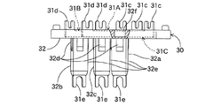
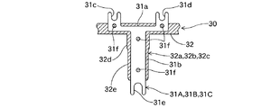
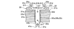
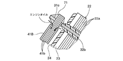
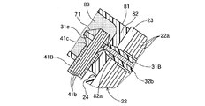
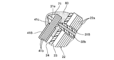
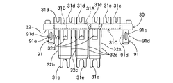
【解決手段】端子板セット30は、貫通取付孔27A、27B、27Cに取付脚部32a、32b、32cを圧入固定したとき、各端子板31A、31B、31Cの横棒部31aの2つのターミナル部31c、31dが回転子1の奥側に位置するとともに各端子板31A、31B、31Cの縦棒部31bの1つのターミナル部31eが回転子1の開放側に位置するよう構成され、かつ、各端子板31A、31B、31Cの横棒部31aの2つのターミナル部31c、31dが各々当該ターミナル部31c、31dに結線されるコイル引出線25a、25bの端部近くに位置するよう横棒部31aの長さが予め調節されている。
【選択図】図9
Description
しかし、出力電流が40A以上になると、コイル26の径φは1.3mm以上必要になり太くなるため、コイル引出線25を這い回して位置Aに集める作業を手作業で行ったり、図27,28に示すようにコイル26にコイル引出線25を固定するためにコイル引出線25を互いに巻きつけて束ねる作業を手作業で行うと、作業者の手が痛くなるという問題が発生する。
また、出力電流を増大させると出力用リード線41も太くする必要があるため、2本の太いコイル引出線25と1本の太い出力用リード線41とを一体に結線すると結線箇所の剛性が増大し、この結線箇所に半田付けを行う作業やこの結線箇所を図29に示すようなクリップ43で固定する作業を手作業で行う際、コイル引出線25が硬くて容易に動かないため作業者の手が痛くなるという問題が発生する。
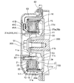
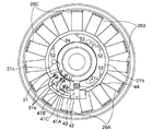
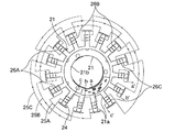
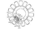
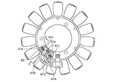
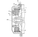
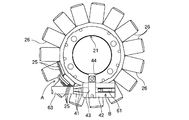
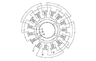
1 回転子
2 固定子
13 希土類磁石
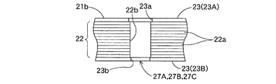
21 コア
21a 巻線部
21b 環状部
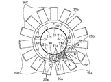
25A、25B、25C 銅線
25a、25b コイル引出線
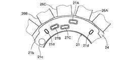
26A、26B、26C コイル群
27A、27B、27C 貫通取付孔
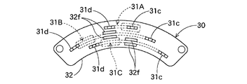
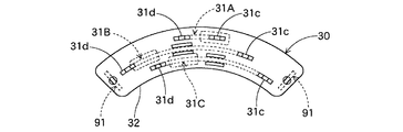
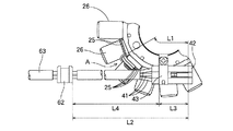
30 端子板セット
31A、31B、31C 端子板
31a 横棒部
31b 縦棒部
31c、31d ターミナル部
31e ターミナル部
31f 結合孔
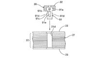
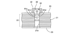
32 樹脂成形体(結合部)
32a、32b、32c 取付脚部(圧入樹脂部)
41A、41B、41C 出力用リード線
41c 切口部
83 シール材
91 保持金具部
Claims (6)
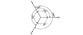
- 希土類磁石を用い極数が4n(n:4〜8のいずれかの整数)の回転子と、3つのコイル群を有し極数が3nの固定子とを備え、前記各コイル群は、粉体樹脂塗装されたコアの巻線部に径φが1.3mm〜2mmの銅線を2コイル飛びに同じ方向に集中巻して構成されるとともに、電気角位相差が約240°となるよう互いにデルタ結線される三相磁石式発電機であって、
前記コアの巻線部の基端側の環状部に貫通取付孔を形成するとともに、該貫通取付孔に固着される端子板セットを設け、
前記端子板セットは、
各々横棒部と縦棒部とからなる略T字形の3個の端子板と、該3個の端子板を固定保持する樹脂成形体とにより構成され、
前記各端子板は、前記横棒部にコイル引出線結線用の2つのターミナル部を有するとともに前記縦棒部の先端に出力用リード線結線用の1つのターミナル部を有し、
前記樹脂成形体は、前記横棒部の2つのターミナル部と前記縦棒部の1つのターミナル部とを除いて前記3個の端子板を囲包み固定するとともに前記縦棒部の周囲に前記貫通取付孔に圧入固定される取付脚部が形成されており、
前記端子板セットは、前記貫通取付孔に前記取付脚部を圧入固定したとき、前記各端子板の横棒部の2つのターミナル部が回転子の奥側に位置するとともに前記各端子板の縦棒部の1つのターミナル部が回転子の開放側に位置するよう構成され、かつ、前記各端子板の横棒部の2つのターミナル部が各々当該ターミナル部に結線されるコイル引出線の端部近くに位置するよう横棒部の長さが予め調節されて構成されている
ことを特徴とする三相磁石式発電機。 - 前記各端子板に、樹脂が充填された結合孔が形成されていることを特徴とする請求項1に記載の三相磁石式発電機。
- コイル引出線の集約部をコアの一端側に配すると共に、出力用リード線との接続をコアの他端側で行う三相磁石式発電機であって、
前記集約部から前記コア他端側に接続するための複数のターミナル部と、このターミナル部を一体的に結合する結合部とを備えることを特徴とする三相磁石式発電機。 - 前記結合部は、該結合部を前記コアに固定するための保持金具部を有していることを特徴とする請求項3に記載の三相磁石式発電機。
- 前記ターミナル部は、該ターミナル部の前記コアへの結合強度を高めるための圧入樹脂部を有していることを特徴とする請求項3又は4に記載の三相磁石式発電機。
- 前記出力用リード線の切口部はシール材で覆われることを特徴とする請求項3に記載の三相磁石式発電機。
Priority Applications (2)
| Application Number | Priority Date | Filing Date | Title |
|---|---|---|---|
| JP2005219318A JP4660310B2 (ja) | 2004-11-04 | 2005-07-28 | 三相磁石式発電機 |
| US11/256,165 US7501729B2 (en) | 2004-11-04 | 2005-10-24 | Three-phase magnetic generator |
Applications Claiming Priority (2)
| Application Number | Priority Date | Filing Date | Title |
|---|---|---|---|
| JP2004320629 | 2004-11-04 | ||
| JP2005219318A JP4660310B2 (ja) | 2004-11-04 | 2005-07-28 | 三相磁石式発電機 |
Publications (2)
| Publication Number | Publication Date |
|---|---|
| JP2006158181A true JP2006158181A (ja) | 2006-06-15 |
| JP4660310B2 JP4660310B2 (ja) | 2011-03-30 |
Family
ID=36260997
Family Applications (1)
| Application Number | Title | Priority Date | Filing Date |
|---|---|---|---|
| JP2005219318A Expired - Fee Related JP4660310B2 (ja) | 2004-11-04 | 2005-07-28 | 三相磁石式発電機 |
Country Status (2)
| Country | Link |
|---|---|
| US (1) | US7501729B2 (ja) |
| JP (1) | JP4660310B2 (ja) |
Cited By (7)
| Publication number | Priority date | Publication date | Assignee | Title |
|---|---|---|---|---|
| JP2009189156A (ja) * | 2008-02-06 | 2009-08-20 | Mitsuba Corp | 回転電機及び回転電機のシール方法 |
| JP2010273482A (ja) * | 2009-05-22 | 2010-12-02 | Denso Trim Kk | 三相磁石発電機 |
| JP2013158144A (ja) * | 2012-01-30 | 2013-08-15 | Mitsuba Corp | インシュレータ、及び回転電機 |
| WO2016129287A1 (ja) * | 2015-02-12 | 2016-08-18 | デンソートリム株式会社 | 内燃機関用回転電機およびそのステータ |
| JP2016171641A (ja) * | 2015-03-12 | 2016-09-23 | 本田技研工業株式会社 | 多極三相式回転電機 |
| WO2017154466A1 (ja) * | 2016-03-10 | 2017-09-14 | デンソートリム株式会社 | 回転電機 |
| JP2018029478A (ja) * | 2015-10-28 | 2018-02-22 | デンソートリム株式会社 | 内燃機関用回転電機 |
Families Citing this family (17)
| Publication number | Priority date | Publication date | Assignee | Title |
|---|---|---|---|---|
| JP4081100B2 (ja) * | 2005-03-28 | 2008-04-23 | 松下電器産業株式会社 | 三相dcブラシレスモータ及び巻線方法 |
| US7615899B2 (en) * | 2005-12-13 | 2009-11-10 | Mitsubishi Electric Corporation | Magneto generator with arrangements for lead wires of three-phase windings |
| US7808137B2 (en) * | 2006-10-05 | 2010-10-05 | Remy Technologies, L.L.C. | Single track layer stator terminal assembly |
| CN101826761B (zh) * | 2009-03-05 | 2012-11-07 | 中山大洋电机股份有限公司 | 一种注塑定子 |
| US9318936B2 (en) * | 2010-07-21 | 2016-04-19 | Romaine Electric | Alternator stator lead and terminal insulator assembly |
| JP2012110188A (ja) * | 2010-11-19 | 2012-06-07 | Nippon Densan Corp | 中間接続部材、ステータ及びモータ |
| KR101750116B1 (ko) * | 2010-11-30 | 2017-06-22 | 엘지이노텍 주식회사 | 후크 터미널 |
| JP5263368B2 (ja) * | 2011-03-08 | 2013-08-14 | 株式会社豊田自動織機 | 電動圧縮機、及び電動圧縮機の組付方法 |
| JP5506836B2 (ja) * | 2012-02-10 | 2014-05-28 | デンソートリム株式会社 | 磁石式発電機 |
| WO2013146401A1 (ja) * | 2012-03-30 | 2013-10-03 | 本田技研工業株式会社 | 回転電機 |
| JP5490290B1 (ja) | 2013-06-06 | 2014-05-14 | 三菱電機株式会社 | 電動パワーアシスト用モータ装置の給電部構造 |
| JP5897062B2 (ja) * | 2014-05-08 | 2016-03-30 | 三菱電機株式会社 | 圧縮機用電動機及び圧縮機及び冷凍サイクル装置及び圧縮機用電動機の製造方法 |
| JP6382698B2 (ja) * | 2014-11-26 | 2018-08-29 | トヨタ自動車株式会社 | 三相回転電機 |
| CN107689700B (zh) * | 2016-08-05 | 2021-06-04 | 德昌电机(深圳)有限公司 | 定子及应用该定子的电机 |
| WO2018105596A1 (ja) * | 2016-12-06 | 2018-06-14 | デンソートリム株式会社 | 内燃機関用回転電機およびそのステータ |
| KR102852657B1 (ko) * | 2021-01-29 | 2025-08-29 | 현대모비스 주식회사 | 모터용 터미널 블록 |
| US12451756B2 (en) * | 2022-06-16 | 2025-10-21 | Ford Global Technologies, Llc | Electric machine |
Citations (3)
| Publication number | Priority date | Publication date | Assignee | Title |
|---|---|---|---|---|
| JPS59162756A (ja) * | 1983-03-03 | 1984-09-13 | Nippon Denso Co Ltd | 磁石発電機の固定子 |
| JPH02303341A (ja) * | 1989-05-17 | 1990-12-17 | Kusatsu Denki Kk | 電動機 |
| JP2003047189A (ja) * | 2001-07-30 | 2003-02-14 | Tamagawa Seiki Co Ltd | プリント基板を有するステータ構造 |
Family Cites Families (5)
| Publication number | Priority date | Publication date | Assignee | Title |
|---|---|---|---|---|
| JP2528848Y2 (ja) * | 1988-09-29 | 1997-03-12 | 株式会社三協精機製作所 | 外転型ブラシレスモータ |
| MY109836A (en) * | 1991-04-30 | 1997-08-30 | Kk Sankyo Seiki Seisakusho | Stator of rotating electric machine. |
| JP3491510B2 (ja) * | 1997-12-05 | 2004-01-26 | 国産電機株式会社 | 磁石発電機用固定子 |
| JPH11103551A (ja) * | 1997-09-29 | 1999-04-13 | Sawafuji Electric Co Ltd | アウタロータ型多極発電機におけるコイル接続構造 |
| JP2003259588A (ja) | 2002-02-28 | 2003-09-12 | Mitsuba Corp | ターミナル挿通部を有するコイルボビン |
-
2005
- 2005-07-28 JP JP2005219318A patent/JP4660310B2/ja not_active Expired - Fee Related
- 2005-10-24 US US11/256,165 patent/US7501729B2/en active Active
Patent Citations (3)
| Publication number | Priority date | Publication date | Assignee | Title |
|---|---|---|---|---|
| JPS59162756A (ja) * | 1983-03-03 | 1984-09-13 | Nippon Denso Co Ltd | 磁石発電機の固定子 |
| JPH02303341A (ja) * | 1989-05-17 | 1990-12-17 | Kusatsu Denki Kk | 電動機 |
| JP2003047189A (ja) * | 2001-07-30 | 2003-02-14 | Tamagawa Seiki Co Ltd | プリント基板を有するステータ構造 |
Cited By (13)
| Publication number | Priority date | Publication date | Assignee | Title |
|---|---|---|---|---|
| JP2009189156A (ja) * | 2008-02-06 | 2009-08-20 | Mitsuba Corp | 回転電機及び回転電機のシール方法 |
| JP2010273482A (ja) * | 2009-05-22 | 2010-12-02 | Denso Trim Kk | 三相磁石発電機 |
| JP2013158144A (ja) * | 2012-01-30 | 2013-08-15 | Mitsuba Corp | インシュレータ、及び回転電機 |
| JP6079944B2 (ja) * | 2015-02-12 | 2017-02-15 | デンソートリム株式会社 | 内燃機関用回転電機およびそのステータ |
| WO2016129287A1 (ja) * | 2015-02-12 | 2016-08-18 | デンソートリム株式会社 | 内燃機関用回転電機およびそのステータ |
| CN107210660A (zh) * | 2015-02-12 | 2017-09-26 | 电装多利牡株式会社 | 内燃机用旋转电机及其定子 |
| JP2016171641A (ja) * | 2015-03-12 | 2016-09-23 | 本田技研工業株式会社 | 多極三相式回転電機 |
| CN105978205A (zh) * | 2015-03-12 | 2016-09-28 | 本田技研工业株式会社 | 多极三相式旋转电机 |
| JP2018029478A (ja) * | 2015-10-28 | 2018-02-22 | デンソートリム株式会社 | 内燃機関用回転電機 |
| CN108352757A (zh) * | 2015-10-28 | 2018-07-31 | 电装多利牡株式会社 | 内燃机用旋转电机 |
| CN108352757B (zh) * | 2015-10-28 | 2020-03-31 | 电装多利牡株式会社 | 内燃机用旋转电机 |
| WO2017154466A1 (ja) * | 2016-03-10 | 2017-09-14 | デンソートリム株式会社 | 回転電機 |
| JPWO2017154466A1 (ja) * | 2016-03-10 | 2018-09-13 | デンソートリム株式会社 | 回転電機 |
Also Published As
| Publication number | Publication date |
|---|---|
| US7501729B2 (en) | 2009-03-10 |
| JP4660310B2 (ja) | 2011-03-30 |
| US20060091746A1 (en) | 2006-05-04 |
Similar Documents
| Publication | Publication Date | Title |
|---|---|---|
| JP4660310B2 (ja) | 三相磁石式発電機 | |
| US11444502B2 (en) | Coil bobbin, stator core of distributed winding radial gap-type rotating electric machine, and distributed winding radial gap-type rotating electric machine | |
| KR101865230B1 (ko) | 분할 코어 형 모터 및 분할 코어 형 모터의 전기자의 제조 방법 | |
| US6566779B2 (en) | Coil winding for DC machine | |
| US6664677B2 (en) | Vehicle-onboard AC generator | |
| JP5506836B2 (ja) | 磁石式発電機 | |
| US6137198A (en) | Stator for a magneto generator | |
| US6278206B1 (en) | Electrical connection apparatus and method for connecting an alternator stator | |
| JP4344695B2 (ja) | アウタロータ型多極発電機用ステータ及びその組立方法 | |
| JP6499371B2 (ja) | 回転電機 | |
| WO2013118777A1 (ja) | 磁石式発電機 | |
| JP2011055654A (ja) | 電動機の冷却構造 | |
| JP2008029127A (ja) | 車両用回転電機 | |
| EP1168570A2 (en) | Coil winding for DC machine | |
| JP2013027118A (ja) | ステータおよび回転電機 | |
| US7095144B2 (en) | Rectifying apparatus of AC generator for vehicle | |
| JP2010074877A (ja) | 回転電機および整流器用ヒートシンクの製造方法 | |
| JP7150171B2 (ja) | 回転電機の固定子、端子台及び回転電機 | |
| JP5159658B2 (ja) | 回転電機 | |
| JP7774498B2 (ja) | 回転電機のステータ構造 | |
| CN106921265B (zh) | 转子及其制造方法、以及dc电动机 | |
| JP2020171110A (ja) | 回転電機 | |
| JP7768812B2 (ja) | アウタロータ型回転電機用ステータおよびその組立方法 | |
| JP7787006B2 (ja) | 回転電機のステータ構造 | |
| WO2024185370A1 (ja) | 回転電機、回転電機用ステータ、回転電機用ステータの中性点ターミナル、及び回転電機用ステータの製造方法 |
Legal Events
| Date | Code | Title | Description |
|---|---|---|---|
| A621 | Written request for application examination |
Free format text: JAPANESE INTERMEDIATE CODE: A621 Effective date: 20071011 |
|
| A977 | Report on retrieval |
Free format text: JAPANESE INTERMEDIATE CODE: A971007 Effective date: 20100706 |
|
| A131 | Notification of reasons for refusal |
Free format text: JAPANESE INTERMEDIATE CODE: A131 Effective date: 20100713 |
|
| A521 | Written amendment |
Free format text: JAPANESE INTERMEDIATE CODE: A523 Effective date: 20100903 |
|
| TRDD | Decision of grant or rejection written | ||
| A01 | Written decision to grant a patent or to grant a registration (utility model) |
Free format text: JAPANESE INTERMEDIATE CODE: A01 Effective date: 20101207 |
|
| A01 | Written decision to grant a patent or to grant a registration (utility model) |
Free format text: JAPANESE INTERMEDIATE CODE: A01 |
|
| A61 | First payment of annual fees (during grant procedure) |
Free format text: JAPANESE INTERMEDIATE CODE: A61 Effective date: 20101228 |
|
| FPAY | Renewal fee payment (event date is renewal date of database) |
Free format text: PAYMENT UNTIL: 20140107 Year of fee payment: 3 |
|
| R150 | Certificate of patent or registration of utility model |
Free format text: JAPANESE INTERMEDIATE CODE: R150 |
|
| LAPS | Cancellation because of no payment of annual fees |