JP2005299875A - ボルト締結構造 - Google Patents
ボルト締結構造 Download PDFInfo
- Publication number
- JP2005299875A JP2005299875A JP2004120030A JP2004120030A JP2005299875A JP 2005299875 A JP2005299875 A JP 2005299875A JP 2004120030 A JP2004120030 A JP 2004120030A JP 2004120030 A JP2004120030 A JP 2004120030A JP 2005299875 A JP2005299875 A JP 2005299875A
- Authority
- JP
- Japan
- Prior art keywords
- bolt
- protrusion
- fastening structure
- bolts
- connecting plate
- Prior art date
- Legal status (The legal status is an assumption and is not a legal conclusion. Google has not performed a legal analysis and makes no representation as to the accuracy of the status listed.)
- Granted
Links
Images


Landscapes
- Connection Of Plates (AREA)
Abstract
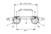
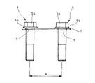
【解決手段】被締結部材11,12に穿設してあるボルト孔13,14に挿通可能な二本のボルト5と、連結プレート15とを備え、連結プレート15の各端部にボルト5の頭部5aにボルト軸線に対して偏心した突起16を設け、この突起16を連結プレート15に枢着している。
これにより、二本のボルト5を連結プレート15に保持しつつ、ボルト5の間隔の拡縮を許容する。
【選択図】図1
Description
{W1−(W2+W3)}≦W0≦(W1+W2+W3)
の範囲で拡縮することとなる。
W1:連結プレート15における突起16の枢支点間隔
W2:一方のボルト5のボルト軸線に対する突起16の偏心量
W3:他方のボルト5のボルト軸線に対する突起16の偏心量
5a 頭部
11 被締結部材
12 被締結部材
13 ボルト孔
14 ボルト孔
15 連結プレート
16 突起
Claims (4)
- 平行に並び且つ被締結部材に穿設してあるボルト孔に挿通可能な複数のボルトと、連結プレートとを備え、当該連結プレートに各ボルトの頭部を、ボルト軸線に対して偏心するように枢着したことを特徴とするボルト締結構造。
- 各ボルトの頭部にボルト軸線に対して偏心した突起を設け、当該突起を連結プレートに枢着した請求項1に記載のボルト締結構造。
- 突起をボルトの頭部に一体的に形成した請求項2に記載のボルト締結構造。
- ボルトの頭部に別部材を固着して突起とした請求項2に記載のボルト締結構造。
Priority Applications (1)
| Application Number | Priority Date | Filing Date | Title |
|---|---|---|---|
| JP2004120030A JP4568012B2 (ja) | 2004-04-15 | 2004-04-15 | ボルト締結構造 |
Applications Claiming Priority (1)
| Application Number | Priority Date | Filing Date | Title |
|---|---|---|---|
| JP2004120030A JP4568012B2 (ja) | 2004-04-15 | 2004-04-15 | ボルト締結構造 |
Publications (2)
| Publication Number | Publication Date |
|---|---|
| JP2005299875A true JP2005299875A (ja) | 2005-10-27 |
| JP4568012B2 JP4568012B2 (ja) | 2010-10-27 |
Family
ID=35331640
Family Applications (1)
| Application Number | Title | Priority Date | Filing Date |
|---|---|---|---|
| JP2004120030A Expired - Fee Related JP4568012B2 (ja) | 2004-04-15 | 2004-04-15 | ボルト締結構造 |
Country Status (1)
| Country | Link |
|---|---|
| JP (1) | JP4568012B2 (ja) |
Cited By (1)
| Publication number | Priority date | Publication date | Assignee | Title |
|---|---|---|---|---|
| GB2495742A (en) * | 2011-10-19 | 2013-04-24 | Simpson Strong Tie Co Inc | Securing device for a tensioning system for reinforcing trusses in a roof |
Families Citing this family (1)
| Publication number | Priority date | Publication date | Assignee | Title |
|---|---|---|---|---|
| SE541741C2 (en) * | 2016-08-22 | 2019-12-03 | Scania Cv Ab | A locking plate unit comprising a locking plate and two adhered fasteners and a vehicle comprising such a locking plate unit |
Citations (7)
| Publication number | Priority date | Publication date | Assignee | Title |
|---|---|---|---|---|
| JPS5675313U (ja) * | 1979-11-12 | 1981-06-19 | ||
| JPS6391716U (ja) * | 1986-12-04 | 1988-06-14 | ||
| JPH0165917U (ja) * | 1987-10-16 | 1989-04-27 | ||
| JPH0231912U (ja) * | 1988-08-23 | 1990-02-28 | ||
| JPH04129915U (ja) * | 1991-05-24 | 1992-11-30 | 石川島播磨重工業株式会社 | ボルト・ナツトの落下防止装置 |
| JPH1186920A (ja) * | 1997-09-11 | 1999-03-30 | Showa Electric Wire & Cable Co Ltd | ケーブル終端接続部の連結電極 |
| JP2002250327A (ja) * | 2001-02-22 | 2002-09-06 | Takeshita:Kk | 連結金具 |
-
2004
- 2004-04-15 JP JP2004120030A patent/JP4568012B2/ja not_active Expired - Fee Related
Patent Citations (7)
| Publication number | Priority date | Publication date | Assignee | Title |
|---|---|---|---|---|
| JPS5675313U (ja) * | 1979-11-12 | 1981-06-19 | ||
| JPS6391716U (ja) * | 1986-12-04 | 1988-06-14 | ||
| JPH0165917U (ja) * | 1987-10-16 | 1989-04-27 | ||
| JPH0231912U (ja) * | 1988-08-23 | 1990-02-28 | ||
| JPH04129915U (ja) * | 1991-05-24 | 1992-11-30 | 石川島播磨重工業株式会社 | ボルト・ナツトの落下防止装置 |
| JPH1186920A (ja) * | 1997-09-11 | 1999-03-30 | Showa Electric Wire & Cable Co Ltd | ケーブル終端接続部の連結電極 |
| JP2002250327A (ja) * | 2001-02-22 | 2002-09-06 | Takeshita:Kk | 連結金具 |
Cited By (1)
| Publication number | Priority date | Publication date | Assignee | Title |
|---|---|---|---|---|
| GB2495742A (en) * | 2011-10-19 | 2013-04-24 | Simpson Strong Tie Co Inc | Securing device for a tensioning system for reinforcing trusses in a roof |
Also Published As
| Publication number | Publication date |
|---|---|
| JP4568012B2 (ja) | 2010-10-27 |
Similar Documents
| Publication | Publication Date | Title |
|---|---|---|
| US10508741B2 (en) | Coupling device for the rotary coupling of a pivot shaft of a flap diaphragm of an exhaust gas flap with a drive element | |
| JP3228322U (ja) | 操作ヘッドを備えるハンドツール | |
| WO2011152103A1 (ja) | 解体切断機 | |
| JP4568012B2 (ja) | ボルト締結構造 | |
| JP2001020392A (ja) | 構造部材の接合構造 | |
| JPH11138362A (ja) | C形リング部材着脱治具 | |
| JP2003306095A (ja) | 車両用バンパ取付構造 | |
| JP2004116516A (ja) | エンジンのシリンダヘッドカバー及びその組立方法 | |
| JP7034282B2 (ja) | ミキサー車 | |
| JP4849361B2 (ja) | 自動車のフードヒンジ取付構造 | |
| JP3711395B2 (ja) | 共回り防止キャップ | |
| JP4412308B2 (ja) | ストッパ構造及びストッパ部材取付け構造 | |
| JP6548983B2 (ja) | ライセンスプレートブラケットの取付構造 | |
| JP7146476B2 (ja) | 鋼管杭と鉄筋の定着方法 | |
| JP2007153111A (ja) | ワイパ装置 | |
| JP6407068B2 (ja) | コンバイン | |
| JP4863368B2 (ja) | 金具及びそれを用いたリップを有する溝形鋼の接合方法 | |
| JP2003011633A (ja) | 産業車両の操舵装置 | |
| JP6623975B2 (ja) | 車両組立装置、ロボット用補強治具 | |
| JP2004132518A (ja) | 固定具 | |
| JP3317081B2 (ja) | チルト式ステアリング装置 | |
| JP5297115B2 (ja) | 破砕装置 | |
| JP4643946B2 (ja) | 鉄骨軸組架構の接合部構造およびワンサイドボルトシステム | |
| JP2026007017A (ja) | カシメ加工装置 | |
| JP3111961U (ja) | エアインパクトレンチの打撃部の構造 |
Legal Events
| Date | Code | Title | Description |
|---|---|---|---|
| A621 | Written request for application examination |
Free format text: JAPANESE INTERMEDIATE CODE: A621 Effective date: 20070326 |
|
| A977 | Report on retrieval |
Free format text: JAPANESE INTERMEDIATE CODE: A971007 Effective date: 20090401 |
|
| A131 | Notification of reasons for refusal |
Free format text: JAPANESE INTERMEDIATE CODE: A131 Effective date: 20100216 |
|
| A521 | Written amendment |
Free format text: JAPANESE INTERMEDIATE CODE: A523 Effective date: 20100414 |
|
| TRDD | Decision of grant or rejection written | ||
| A01 | Written decision to grant a patent or to grant a registration (utility model) |
Free format text: JAPANESE INTERMEDIATE CODE: A01 Effective date: 20100803 |
|
| A01 | Written decision to grant a patent or to grant a registration (utility model) |
Free format text: JAPANESE INTERMEDIATE CODE: A01 |
|
| A61 | First payment of annual fees (during grant procedure) |
Free format text: JAPANESE INTERMEDIATE CODE: A61 Effective date: 20100806 |
|
| R150 | Certificate of patent or registration of utility model |
Ref document number: 4568012 Country of ref document: JP Free format text: JAPANESE INTERMEDIATE CODE: R150 Free format text: JAPANESE INTERMEDIATE CODE: R150 |
|
| FPAY | Renewal fee payment (event date is renewal date of database) |
Free format text: PAYMENT UNTIL: 20130813 Year of fee payment: 3 |
|
| LAPS | Cancellation because of no payment of annual fees |