EP4528123A2 - Kraftübertragungsvorrichtung - Google Patents
Kraftübertragungsvorrichtung Download PDFInfo
- Publication number
- EP4528123A2 EP4528123A2 EP25155601.5A EP25155601A EP4528123A2 EP 4528123 A2 EP4528123 A2 EP 4528123A2 EP 25155601 A EP25155601 A EP 25155601A EP 4528123 A2 EP4528123 A2 EP 4528123A2
- Authority
- EP
- European Patent Office
- Prior art keywords
- clutch
- cam
- clutch plates
- pressure member
- side clutch
- Prior art date
- Legal status (The legal status is an assumption and is not a legal conclusion. Google has not performed a legal analysis and makes no representation as to the accuracy of the status listed.)
- Pending
Links
Images


Classifications
-
- F—MECHANICAL ENGINEERING; LIGHTING; HEATING; WEAPONS; BLASTING
- F16—ENGINEERING ELEMENTS AND UNITS; GENERAL MEASURES FOR PRODUCING AND MAINTAINING EFFECTIVE FUNCTIONING OF MACHINES OR INSTALLATIONS; THERMAL INSULATION IN GENERAL
- F16D—COUPLINGS FOR TRANSMITTING ROTATION; CLUTCHES; BRAKES
- F16D13/00—Friction clutches
- F16D13/22—Friction clutches with axially-movable clutching members
- F16D13/38—Friction clutches with axially-movable clutching members with flat clutching surfaces, e.g. discs
- F16D13/52—Clutches with multiple lamellae ; Clutches in which three or more axially moveable members are fixed alternately to the shafts to be coupled and are pressed from one side towards an axially-located member
- F16D13/54—Clutches with multiple lamellae ; Clutches in which three or more axially moveable members are fixed alternately to the shafts to be coupled and are pressed from one side towards an axially-located member with means for increasing the effective force between the actuating sleeve or equivalent member and the pressure member
- F16D13/56—Clutches with multiple lamellae ; Clutches in which three or more axially moveable members are fixed alternately to the shafts to be coupled and are pressed from one side towards an axially-located member with means for increasing the effective force between the actuating sleeve or equivalent member and the pressure member in which the clutching pressure is produced by springs only
-
- F—MECHANICAL ENGINEERING; LIGHTING; HEATING; WEAPONS; BLASTING
- F16—ENGINEERING ELEMENTS AND UNITS; GENERAL MEASURES FOR PRODUCING AND MAINTAINING EFFECTIVE FUNCTIONING OF MACHINES OR INSTALLATIONS; THERMAL INSULATION IN GENERAL
- F16D—COUPLINGS FOR TRANSMITTING ROTATION; CLUTCHES; BRAKES
- F16D13/00—Friction clutches
- F16D13/22—Friction clutches with axially-movable clutching members
- F16D13/38—Friction clutches with axially-movable clutching members with flat clutching surfaces, e.g. discs
- F16D13/52—Clutches with multiple lamellae ; Clutches in which three or more axially moveable members are fixed alternately to the shafts to be coupled and are pressed from one side towards an axially-located member
-
- F—MECHANICAL ENGINEERING; LIGHTING; HEATING; WEAPONS; BLASTING
- F16—ENGINEERING ELEMENTS AND UNITS; GENERAL MEASURES FOR PRODUCING AND MAINTAINING EFFECTIVE FUNCTIONING OF MACHINES OR INSTALLATIONS; THERMAL INSULATION IN GENERAL
- F16D—COUPLINGS FOR TRANSMITTING ROTATION; CLUTCHES; BRAKES
- F16D23/00—Details of mechanically-actuated clutches not specific for one distinct type
- F16D23/12—Mechanical clutch-actuating mechanisms arranged outside the clutch as such
-
- F—MECHANICAL ENGINEERING; LIGHTING; HEATING; WEAPONS; BLASTING
- F16—ENGINEERING ELEMENTS AND UNITS; GENERAL MEASURES FOR PRODUCING AND MAINTAINING EFFECTIVE FUNCTIONING OF MACHINES OR INSTALLATIONS; THERMAL INSULATION IN GENERAL
- F16D—COUPLINGS FOR TRANSMITTING ROTATION; CLUTCHES; BRAKES
- F16D13/00—Friction clutches
- F16D13/22—Friction clutches with axially-movable clutching members
- F16D13/38—Friction clutches with axially-movable clutching members with flat clutching surfaces, e.g. discs
- F16D13/52—Clutches with multiple lamellae ; Clutches in which three or more axially moveable members are fixed alternately to the shafts to be coupled and are pressed from one side towards an axially-located member
- F16D13/54—Clutches with multiple lamellae ; Clutches in which three or more axially moveable members are fixed alternately to the shafts to be coupled and are pressed from one side towards an axially-located member with means for increasing the effective force between the actuating sleeve or equivalent member and the pressure member
- F16D13/56—Clutches with multiple lamellae ; Clutches in which three or more axially moveable members are fixed alternately to the shafts to be coupled and are pressed from one side towards an axially-located member with means for increasing the effective force between the actuating sleeve or equivalent member and the pressure member in which the clutching pressure is produced by springs only
- F16D2013/565—Clutches with multiple lamellae ; Clutches in which three or more axially moveable members are fixed alternately to the shafts to be coupled and are pressed from one side towards an axially-located member with means for increasing the effective force between the actuating sleeve or equivalent member and the pressure member in which the clutching pressure is produced by springs only with means for releasing the clutch pressure in case of back torque
-
- F—MECHANICAL ENGINEERING; LIGHTING; HEATING; WEAPONS; BLASTING
- F16—ENGINEERING ELEMENTS AND UNITS; GENERAL MEASURES FOR PRODUCING AND MAINTAINING EFFECTIVE FUNCTIONING OF MACHINES OR INSTALLATIONS; THERMAL INSULATION IN GENERAL
- F16D—COUPLINGS FOR TRANSMITTING ROTATION; CLUTCHES; BRAKES
- F16D23/00—Details of mechanically-actuated clutches not specific for one distinct type
- F16D23/12—Mechanical clutch-actuating mechanisms arranged outside the clutch as such
- F16D2023/123—Clutch actuation by cams, ramps or ball-screw mechanisms
Definitions
- the present invention relates to a power transmission device that is capable of appropriately transmitting or cutting off rotational power of an input member to an output member.
- a motorcycle has a power transmission device for appropriately transmitting or cutting off driving power of an engine to a transmission and a driving wheel.
- the power transmission device includes an input member coupled to the engine side, an output member coupled to the transmission and driving wheel side, a clutch member coupled to an output member, and a pressure member that is capable of pressing clutch plates (drive-side clutch plates and driven-side clutch plates) against each other or releasing a press-contact force.
- the power transmission device is configured to transmit power by pressing the drive-side clutch plates and the driven-side clutch plates against each other and to cut off power by releasing the press-contact force.
- a receiving member is attached to the pressure member, and a clutch spring (urging means) contained in the receiving member urges the pressure member in a direction such that the drive-side clutch plates and the driven-side clutch plates are pressed against each other.
- One cam surface is formed in the receiving member, and the other cam surface, which faces the one cam surface, is formed in the clutch member.
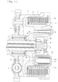
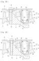
- the pressure member 5 is configured to be capable of pressing the drive-side clutch plates 6 and the driven-side clutch plates 7 against each other or releasing the press-contact force in accordance with movement thereof relative to the clutch member 4 in the axial direction.
- the push rod 9 and the pressed member E which are activated by an operation performed by a driver and which can release the press-contact force between the drive-side clutch plates 6 and the driven-side clutch plates 7 by moving the pressure member 5 against the urging force of the clutch spring 10 (urging means) as described above, constitute “activation means" of the present invention.
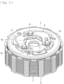
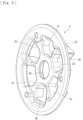
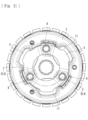
- the attachment holes 5b are formed in the pressure member 5 at a plurality of (three) positions on the same circle at regular intervals, and the receiving member 11 is attached to each of the attachment holes 5b.
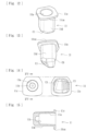
- the receiving member 11, which is attached to the attachment hole 5b of the pressure member 5, can make contact with one end of the clutch spring 10 and receive the urging force thereof, and is separate from the pressure member 5.
- the receiving members 11 are moved in the direction ⁇ in Fig. 19 by the cam function of the first cam surfaces C1 and the second cam surfaces C2 so as to reduce the urging force of the clutch springs 10 transmitted to the pressure member 5, and thereby the press-contact force between the drive-side clutch plates 6 and the driven-side clutch plates 7 is reduced.
- Reduction of the press-contact force refers to a state in which rotational-power transmitting capacity is reduced due to sliding of the drive-side clutch plates 6 and the driven-side clutch plates 7 over each other.
- the fifth cam surface C5 is formed on a side opposite from the first cam surface C1; and the sixth cam surfaces C6 (see Fig. 11 ), each of which faces the fifth cam surface C5, is formed in the pressure member 5. That is, in both side surfaces of the bottom portion of each of the receiving members 11, the first cam surface C1 and the fifth cam surface C5 are respectively formed; and the back-torque limiting cam is constituted by the first cam surfaces C1, the second cam surfaces C2, the fifth cam surfaces C5, and the sixth cam surfaces C6.
- the pressure member 5, and the receiving members 11 When assembling the clutch member 4, the pressure member 5, and the receiving members 11 together, the first cam surfaces C1 formed in the receiving members 11 and the second cam surfaces C2 formed in the clutch member 4 are disposed so as to face each other, and the fifth cam surfaces C5 formed in the receiving members 11 and the sixth cam surfaces C6 formed in the pressure member 5 are disposed so as to face each other.
- the receiving members 11 are moved in the direction ⁇ in Fig.
- the present embodiment includes the rotation restricting portion 8a that is capable of restricting rotation, relative to the clutch member 4, (rotation in a direction such that the first cam surface C1 and the second cam surface C2 become closer to each other) of the pressure member 5 that has moved due to activation of activation means (the push rod 9 and the pressed member E) and is capable of maintaining the clearance between the pair of cam surfaces (the first cam surface C1 and the second cam surface C2) that constitute the back-torque limiting cam. Therefore, with the present embodiment, by restricting rotation of the pressure member 5 when a driver disengages the clutch, it is possible to improve responsiveness when the driver subsequently engages the clutch and to improve operability.
- the present embodiment includes the receiving member 11 that is constituted by a separate member attached to the pressure member 5, that receives an urging force of the clutch spring 10 (urging means) on the pressure member 5 side, and that is capable of transmitting the urging force to the pressure member 5; and the back-torque limiting cam has the first cam surface C1, which is one cam surface, formed in the receiving member 11 and the second cam surface C2, which is the other cam surface, formed in the clutch member 4.
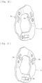
- the rotation restricting portion 8a is formed in a predetermined part of the fixing member 8 (in particular, integrally formed by bending a predetermined part of the fixing member 8). Therefore, by performing replacement to the fixing member 8 having the rotation restricting portion 8a in an existing power transmission device, it is possible to restrict rotation of the pressure member 5 when a driver disengages the clutch, and it is possible to improve responsiveness when the driver subsequently engages the clutch and to improve operability.
- a power transmission device is disposed in a vehicle, such as a motorcycle, and appropriately transmits or cuts off driving power of an engine to the transmission and driving wheel side.
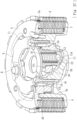
- the power transmission device is mainly composed of: a clutch housing 2 on which a gear 1 as an input member is formed, a clutch member 4 coupled to a shaft 3 as an output member, a pressure member 5 formed on the right-end side of the clutch member 4 in the figure, drive-side clutch plates 6 coupled to the clutch housing 2 side, driven-side clutch plates 7 coupled to the clutch member 4 side, a fixing member 8, a push rod 9, clutch springs 10 as urging means, and receiving members 11.
- Elements that are the same as those of the first embodiment will be denoted by the same numerals, and detailed descriptions of such elements will be omitted.
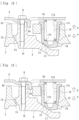
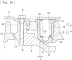
- the press-contact assisting cam is configured as follows: when assembling the clutch member 4 and the pressure member 5 together, the third cam surfaces C3 formed in the pressure member 5 and the fourth cam surfaces C4 formed in the clutch member 4 are disposed so as to face each other; thus, if the pressure member 5 and the clutch member 4 rotate relative to each other when rotational power input to the gear 1 becomes capable of being transmitted to the shaft 3, the pressure member 5 is moved in the direction ⁇ in Fig. 23 by the cam function of the third cam surfaces C3 and the fourth cam surfaces C4 so that the pressure member 5 becomes closer to the clutch member 4; and thereby the press-contact force between the drive-side clutch plates 6 and the driven-side clutch plates 7 is increased.
- the back-torque limiting cam is configured as follows: when assembling the clutch member 4, the pressure member 5, and the receiving members 11 together, the first cam surfaces C1 formed in the bottom side surfaces of the receiving members 11 and the second cam surfaces C2 formed in the clutch member 4 are disposed so as to face each other; thus, if the pressure member 5 and the clutch member 4 rotate relative to each other when the rotation speed of the shaft 3 exceeds the rotation speed of the gear 1, the receiving members 11 are moved in the direction ⁇ in Fig.
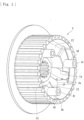
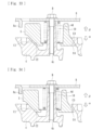
- a rotation restricting portion 5e is integrally formed in a predetermined part of the pressure member 5 according to the present embodiment.
- the rotation restricting portion 5e is capable of restricting rotation, relative to the clutch member 4, of the pressure member 5 that has moved due to activation of the push rod 9 and the pressed member E (activation means) and is capable of maintaining the clearance t (see Fig. 25 ) between a pair of cam surfaces (the first cam surface C1 and the second cam surface C2) that constitute the back-torque limiting cam.
- the rotation restricting portion 5e is formed by causing a predetermined part of the pressure member 5 to protrude in the rotation direction of the pressure member 5.
- the rotation restricting portion 5e is configured to be capable of preventing the pressure member 5 from rotating and the receiving member 11 from becoming stuck onto the second cam surface C2 when the activation means (the push rod 9 and the pressed member E) are activated.
- a part that interferes with the rotation restricting portion 5e is not limited to the boss portion 4d of the clutch member 4, and may be another part (including a separately and newly formed part).
- the present embodiment includes the rotation restricting portion 5e that is capable of restricting rotation, relative to the clutch member 4, (rotation in a direction such that the first cam surface C1 and the second cam surface C2 become closer to each other) of the pressure member 5 that has moved due to activation of activation means (the push rod 9 and the pressed member E) and is capable of maintaining the clearance between the pair of cam surfaces (the first cam surface C1 and the second cam surface C2) that constitute the back-torque limiting cam. Therefore, with the present embodiment, by restricting rotation of the pressure member 5 when a driver disengages the clutch, it is possible to improve responsiveness when the driver subsequently engages the clutch and to improve operability.
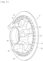
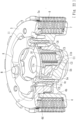
- a rotation restricting portion 4e is integrally formed in a predetermined part of the clutch member 4 according to the present embodiment.
- the rotation restricting portion 4e is capable of restricting rotation, relative to the clutch member 4, of the pressure member 5 that has moved due to activation of the push rod 9 and the pressed member E (activation means) and is capable of maintaining the clearance t (see Fig. 30 ) between a pair of cam surfaces (the first cam surface C1 and the second cam surface C2) that constitute the back-torque limiting cam.
- the rotation restricting portion 4e is formed by causing a predetermined part of the clutch member 4 (a predetermined part of the boss portion 4d in the present embodiment) to protrude in the rotation direction of the pressure member 5.
- the present embodiment includes the receiving member 11 that is constituted by a separate member attached to the pressure member 5, that receives an urging force of the clutch spring 10 (urging means) on the pressure member 5 side, and that is capable of transmitting the urging force to the pressure member 5; and the back-torque limiting cam has the first cam surface C1, which is one cam surface, formed in the receiving member 11 and the second cam surface C2, which is the other cam surface, formed in the clutch member 4.
- the rotation restricting portion 4e is formed in a predetermined part of the clutch member 4, and the pressure member 5 that has moved due to activation of activation means (the push rod 9 and the pressed member E) interferes with the rotation restricting portion 4e formed in the clutch member 4 and restricts rotation of the pressure member 5. Therefore, by partially changing the shape of the clutch member 4, it is possible to restrict rotation of the pressure member 5 when a driver disengages the clutch, and it is possible to improve responsiveness when the driver subsequently engages the clutch and to improve operability.
- a power transmission device is disposed in a vehicle, such as a motorcycle, and appropriately transmits or cuts off driving power of an engine to the transmission and driving wheel side.
- the power transmission device is mainly composed of: a clutch housing 2 on which a gear 1 as an input member is formed, a clutch member 4 coupled to a shaft 3 as an output member, a pressure member 5 formed on the right-end side of the clutch member 4 in the figure, drive-side clutch plates 6 coupled to the clutch housing 2 side, driven-side clutch plates 7 coupled to the clutch member 4 side, a fixing member 8, a push rod 9, and clutch springs 10 as urging means.
- Elements that are the same as those of the first embodiment will be denoted by the same numerals, and detailed descriptions of such elements will be omitted.
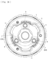
- the power transmission device according to the present embodiment does not have the receiving members 11 included in the first to third embodiments.
- the press-contact assisting cam is configured as follows: when assembling the clutch member 4 and the pressure member 5 together, the third cam surfaces C3 formed in the pressure member 5 and the fourth cam surfaces C4 formed in the clutch member 4 are disposed so as to face each other; thus, if the pressure member 5 and the clutch member 4 rotate relative to each other when rotational power input to the gear 1 becomes capable of being transmitted to the shaft 3, the pressure member 5 is moved in the direction ⁇ in Fig. 33 by the cam function of the third cam surfaces C3 and the fourth cam surfaces C4 so that the pressure member 5 becomes closer to the clutch member 4; and thereby the press-contact force between the drive-side clutch plates 6 and the driven-side clutch plates 7 is increased.
- the back-torque limiting cam is configured as follows: when assembling the clutch member 4 and the pressure member 5 together, the first cam surfaces C1 formed in the pressure member 5 and the second cam surfaces C2 formed in the clutch member 4 are disposed so as to face each other; thus, if the pressure member 5 and the clutch member 4 rotate relative to each other when the rotation speed of the shaft 3 exceeds the rotation speed of the gear 1, the pressure member 5 is moved in the direction ⁇ in Fig. 34 by the cam function of the first cam surfaces C 1 and the second cam surfaces C2; and thereby the press-contact force between the drive-side clutch plates 6 and the driven-side clutch plates 7 is reduced.
- a rotation restricting portion 8a is integrally formed in a predetermined part of the fixing member 8 according to the present embodiment.
- the rotation restricting portion 8a is capable of restricting rotation, relative to the clutch member 4, of the pressure member 5 that has moved due to activation of the push rod 9 and the pressed member E (activation means) and is capable of maintaining the clearance t (see Fig. 35 ) between a pair of cam surfaces (the first cam surface C1 and the second cam surface C2) that constitute the back-torque limiting cam.
- the rotation restricting portion 8a is formed by bending a predetermined part of the fixing member 8.
Landscapes
- Engineering & Computer Science (AREA)
- General Engineering & Computer Science (AREA)
- Mechanical Engineering (AREA)
- Mechanical Operated Clutches (AREA)
- One-Way And Automatic Clutches, And Combinations Of Different Clutches (AREA)
- Glass Compositions (AREA)
Applications Claiming Priority (4)
| Application Number | Priority Date | Filing Date | Title |
|---|---|---|---|
| JP2018002703A JP7217588B2 (ja) | 2018-01-11 | 2018-01-11 | 動力伝達装置 |
| EP19738506.5A EP3739231B1 (de) | 2018-01-11 | 2019-01-09 | Leistungsübertragungsvorrichtung |
| PCT/JP2019/000382 WO2019139045A1 (ja) | 2018-01-11 | 2019-01-09 | 動力伝達装置 |
| EP23214354.5A EP4310355A3 (de) | 2018-01-11 | 2019-01-09 | Kraftübertragungsvorrichtung |
Related Parent Applications (2)
| Application Number | Title | Priority Date | Filing Date |
|---|---|---|---|
| EP19738506.5A Division EP3739231B1 (de) | 2018-01-11 | 2019-01-09 | Leistungsübertragungsvorrichtung |
| EP23214354.5A Division EP4310355A3 (de) | 2018-01-11 | 2019-01-09 | Kraftübertragungsvorrichtung |
Publications (2)
| Publication Number | Publication Date |
|---|---|
| EP4528123A2 true EP4528123A2 (de) | 2025-03-26 |
| EP4528123A3 EP4528123A3 (de) | 2025-06-04 |
Family
ID=67219493
Family Applications (3)
| Application Number | Title | Priority Date | Filing Date |
|---|---|---|---|
| EP25155601.5A Pending EP4528123A3 (de) | 2018-01-11 | 2019-01-09 | Kraftübertragungsvorrichtung |
| EP19738506.5A Active EP3739231B1 (de) | 2018-01-11 | 2019-01-09 | Leistungsübertragungsvorrichtung |
| EP23214354.5A Pending EP4310355A3 (de) | 2018-01-11 | 2019-01-09 | Kraftübertragungsvorrichtung |
Family Applications After (2)
| Application Number | Title | Priority Date | Filing Date |
|---|---|---|---|
| EP19738506.5A Active EP3739231B1 (de) | 2018-01-11 | 2019-01-09 | Leistungsübertragungsvorrichtung |
| EP23214354.5A Pending EP4310355A3 (de) | 2018-01-11 | 2019-01-09 | Kraftübertragungsvorrichtung |
Country Status (6)
| Country | Link |
|---|---|
| US (1) | US11149799B2 (de) |
| EP (3) | EP4528123A3 (de) |
| JP (1) | JP7217588B2 (de) |
| CN (1) | CN111615595B (de) |
| TW (1) | TWI790322B (de) |
| WO (1) | WO2019139045A1 (de) |
Families Citing this family (4)
| Publication number | Priority date | Publication date | Assignee | Title |
|---|---|---|---|---|
| JP6894792B2 (ja) * | 2017-07-27 | 2021-06-30 | 株式会社エフ・シー・シー | 動力伝達装置 |
| JP6903020B2 (ja) * | 2018-01-11 | 2021-07-14 | 株式会社エフ・シー・シー | 動力伝達装置 |
| US11835097B2 (en) * | 2020-04-13 | 2023-12-05 | Kabushiki Kaisha F.C.C. | Power transmission apparatus |
| JP7581288B2 (ja) * | 2022-07-21 | 2024-11-12 | 株式会社エフ・シー・シー | クラッチ装置 |
Citations (1)
| Publication number | Priority date | Publication date | Assignee | Title |
|---|---|---|---|---|
| WO2016024557A1 (ja) | 2014-08-12 | 2016-02-18 | 株式会社エフ・シ-・シ- | 動力伝達装置 |
Family Cites Families (22)
| Publication number | Priority date | Publication date | Assignee | Title |
|---|---|---|---|---|
| JP3378097B2 (ja) * | 1994-09-29 | 2003-02-17 | 本田技研工業株式会社 | 摩擦クラッチ |
| JP3378100B2 (ja) * | 1994-10-28 | 2003-02-17 | 本田技研工業株式会社 | クラッチ構造 |
| JP4252026B2 (ja) * | 2004-11-09 | 2009-04-08 | 株式会社エフ・シー・シー | 動力伝達装置の製造方法 |
| JP4364170B2 (ja) * | 2005-07-14 | 2009-11-11 | 株式会社エフ・シー・シー | 動力伝達装置 |
| JP2011021719A (ja) * | 2009-07-17 | 2011-02-03 | Exedy Corp | 自動二輪車用クラッチ装置 |
| JP5502507B2 (ja) * | 2010-01-27 | 2014-05-28 | 株式会社エフ・シー・シー | 動力伝達装置 |
| JP5995439B2 (ja) * | 2011-12-28 | 2016-09-21 | 株式会社エフ・シー・シー | 動力伝達装置 |
| JP5272089B1 (ja) * | 2012-03-09 | 2013-08-28 | 株式会社エクセディ | モータサイクル用クラッチ装置 |
| JP5854900B2 (ja) | 2012-03-16 | 2016-02-09 | 株式会社エフ・シー・シー | 動力伝達装置 |
| JP5998571B2 (ja) * | 2012-03-28 | 2016-09-28 | 株式会社ジェイテクト | 駆動力伝達装置及びこれを備えた四輪駆動車 |
| FR2990899B1 (fr) * | 2012-05-24 | 2015-07-24 | Poclain Hydraulics Ind | Appareil hydraulique comprenant un assemblage amélioré d'une machine hydraulique et d'un embrayage. |
| CN202746439U (zh) * | 2012-09-14 | 2013-02-20 | 李德军 | 星型摩擦离合器 |
| US20140158489A1 (en) * | 2012-12-06 | 2014-06-12 | Tai-Her Yang | Clutch actuated by inertia mass and friction damping |
| DE102013000975A1 (de) * | 2013-01-22 | 2014-07-24 | Licos Trucktec Gmbh | "Reibschaltkupplung" |
| DE102014203954A1 (de) * | 2013-03-15 | 2014-09-18 | Schaeffler Technologies Gmbh & Co. Kg | Kupplungseinrichtung |
| JP5626936B1 (ja) * | 2013-06-03 | 2014-11-19 | ヤマハ発動機株式会社 | クラッチ及びそれを備える鞍乗型車両 |
| JP6295690B2 (ja) * | 2014-02-04 | 2018-03-20 | スズキ株式会社 | バックトルクリミッターを有するクラッチ |
| JP6104959B2 (ja) * | 2015-02-09 | 2017-03-29 | 本田技研工業株式会社 | クラッチ装置 |
| JP6501354B2 (ja) * | 2015-05-12 | 2019-04-17 | 株式会社エフ・シー・シー | 車両用動力伝達システム |
| JP6801956B2 (ja) * | 2015-12-04 | 2020-12-16 | 株式会社エクセディ | モータサイクル用クラッチ装置 |
| US10161426B2 (en) * | 2016-03-25 | 2018-12-25 | Ford Global Technologies, Llc | Transmission and transmission clutch system |
| JP6710709B2 (ja) * | 2018-01-10 | 2020-06-17 | 本田技研工業株式会社 | 多板式摩擦クラッチ |
-
2018
- 2018-01-11 JP JP2018002703A patent/JP7217588B2/ja active Active
- 2018-12-05 TW TW107143667A patent/TWI790322B/zh active
-
2019
- 2019-01-09 CN CN201980007774.8A patent/CN111615595B/zh active Active
- 2019-01-09 EP EP25155601.5A patent/EP4528123A3/de active Pending
- 2019-01-09 WO PCT/JP2019/000382 patent/WO2019139045A1/ja not_active Ceased
- 2019-01-09 EP EP19738506.5A patent/EP3739231B1/de active Active
- 2019-01-09 EP EP23214354.5A patent/EP4310355A3/de active Pending
-
2020
- 2020-07-10 US US16/925,794 patent/US11149799B2/en active Active
Patent Citations (1)
| Publication number | Priority date | Publication date | Assignee | Title |
|---|---|---|---|---|
| WO2016024557A1 (ja) | 2014-08-12 | 2016-02-18 | 株式会社エフ・シ-・シ- | 動力伝達装置 |
Also Published As
| Publication number | Publication date |
|---|---|
| EP4310355A3 (de) | 2024-04-10 |
| JP7217588B2 (ja) | 2023-02-03 |
| EP3739231A1 (de) | 2020-11-18 |
| EP3739231A4 (de) | 2021-09-29 |
| TWI790322B (zh) | 2023-01-21 |
| US20200340537A1 (en) | 2020-10-29 |
| EP4528123A3 (de) | 2025-06-04 |
| TW201937076A (zh) | 2019-09-16 |
| EP3739231B1 (de) | 2023-12-06 |
| JP2019120393A (ja) | 2019-07-22 |
| CN111615595B (zh) | 2022-07-26 |
| WO2019139045A1 (ja) | 2019-07-18 |
| CN111615595A (zh) | 2020-09-01 |
| US11149799B2 (en) | 2021-10-19 |
| EP4310355A2 (de) | 2024-01-24 |
Similar Documents
| Publication | Publication Date | Title |
|---|---|---|
| JP5502507B2 (ja) | 動力伝達装置 | |
| EP3181933B1 (de) | Leistungsübertragungsvorrichtung | |
| EP2778457B1 (de) | Stromübertragungsvorrichtung | |
| JP4452301B2 (ja) | 動力伝達装置 | |
| EP3739232B1 (de) | Leistungsübertragungsvorrichtung | |
| US11149799B2 (en) | Power transmission device | |
| JP6603143B2 (ja) | 動力伝達装置 | |
| JP6502443B2 (ja) | 動力伝達装置 | |
| JP2019044869A (ja) | 動力伝達装置 | |
| JP2009063023A (ja) | 動力伝達装置 | |
| CN115263943A (zh) | 动力传递装置 | |
| CN115628269B (zh) | 动力传递装置 | |
| JP2009068577A (ja) | 動力伝達装置 | |
| JP4975723B2 (ja) | モータサイクル用クラッチ装置 | |
| JP4669359B2 (ja) | 動力伝達装置 | |
| JP2007205387A (ja) | 動力伝達装置 | |
| JP5324345B2 (ja) | 動力伝達装置 |
Legal Events
| Date | Code | Title | Description |
|---|---|---|---|
| PUAI | Public reference made under article 153(3) epc to a published international application that has entered the european phase |
Free format text: ORIGINAL CODE: 0009012 |
|
| STAA | Information on the status of an ep patent application or granted ep patent |
Free format text: STATUS: THE APPLICATION HAS BEEN PUBLISHED |
|
| AC | Divisional application: reference to earlier application |
Ref document number: 3739231 Country of ref document: EP Kind code of ref document: P Ref document number: 4310355 Country of ref document: EP Kind code of ref document: P |
|
| AK | Designated contracting states |
Kind code of ref document: A2 Designated state(s): AL AT BE BG CH CY CZ DE DK EE ES FI FR GB GR HR HU IE IS IT LI LT LU LV MC MK MT NL NO PL PT RO RS SE SI SK SM TR |
|
| REG | Reference to a national code |
Ref country code: DE Ref legal event code: R079 Free format text: PREVIOUS MAIN CLASS: F16D0013560000 Ipc: F16D0023120000 |
|
| PUAL | Search report despatched |
Free format text: ORIGINAL CODE: 0009013 |
|
| AK | Designated contracting states |
Kind code of ref document: A3 Designated state(s): AL AT BE BG CH CY CZ DE DK EE ES FI FR GB GR HR HU IE IS IT LI LT LU LV MC MK MT NL NO PL PT RO RS SE SI SK SM TR |
|
| RIC1 | Information provided on ipc code assigned before grant |
Ipc: F16D 13/56 20060101ALI20250430BHEP Ipc: F16D 23/12 20060101AFI20250430BHEP |
|
| STAA | Information on the status of an ep patent application or granted ep patent |
Free format text: STATUS: REQUEST FOR EXAMINATION WAS MADE |
|
| 17P | Request for examination filed |
Effective date: 20251203 |