EP4527358A2 - Stent - Google Patents
Stent Download PDFInfo
- Publication number
- EP4527358A2 EP4527358A2 EP25156374.8A EP25156374A EP4527358A2 EP 4527358 A2 EP4527358 A2 EP 4527358A2 EP 25156374 A EP25156374 A EP 25156374A EP 4527358 A2 EP4527358 A2 EP 4527358A2
- Authority
- EP
- European Patent Office
- Prior art keywords
- stent
- clause
- lattice
- circumferential
- helical
- Prior art date
- Legal status (The legal status is an assumption and is not a legal conclusion. Google has not performed a legal analysis and makes no representation as to the accuracy of the status listed.)
- Pending
Links
Images


Classifications
-
- A—HUMAN NECESSITIES
- A61—MEDICAL OR VETERINARY SCIENCE; HYGIENE
- A61F—FILTERS IMPLANTABLE INTO BLOOD VESSELS; PROSTHESES; DEVICES PROVIDING PATENCY TO, OR PREVENTING COLLAPSING OF, TUBULAR STRUCTURES OF THE BODY, e.g. STENTS; ORTHOPAEDIC, NURSING OR CONTRACEPTIVE DEVICES; FOMENTATION; TREATMENT OR PROTECTION OF EYES OR EARS; BANDAGES, DRESSINGS OR ABSORBENT PADS; FIRST-AID KITS
- A61F2/00—Filters implantable into blood vessels; Prostheses, i.e. artificial substitutes or replacements for parts of the body; Appliances for connecting them with the body; Devices providing patency to, or preventing collapsing of, tubular structures of the body, e.g. stents
- A61F2/82—Devices providing patency to, or preventing collapsing of, tubular structures of the body, e.g. stents
- A61F2/86—Stents in a form characterised by the wire-like elements; Stents in the form characterised by a net-like or mesh-like structure
- A61F2/88—Stents in a form characterised by the wire-like elements; Stents in the form characterised by a net-like or mesh-like structure the wire-like elements formed as helical or spiral coils
-
- A—HUMAN NECESSITIES
- A61—MEDICAL OR VETERINARY SCIENCE; HYGIENE
- A61F—FILTERS IMPLANTABLE INTO BLOOD VESSELS; PROSTHESES; DEVICES PROVIDING PATENCY TO, OR PREVENTING COLLAPSING OF, TUBULAR STRUCTURES OF THE BODY, e.g. STENTS; ORTHOPAEDIC, NURSING OR CONTRACEPTIVE DEVICES; FOMENTATION; TREATMENT OR PROTECTION OF EYES OR EARS; BANDAGES, DRESSINGS OR ABSORBENT PADS; FIRST-AID KITS
- A61F2/00—Filters implantable into blood vessels; Prostheses, i.e. artificial substitutes or replacements for parts of the body; Appliances for connecting them with the body; Devices providing patency to, or preventing collapsing of, tubular structures of the body, e.g. stents
- A61F2/82—Devices providing patency to, or preventing collapsing of, tubular structures of the body, e.g. stents
-
- A—HUMAN NECESSITIES
- A61—MEDICAL OR VETERINARY SCIENCE; HYGIENE
- A61F—FILTERS IMPLANTABLE INTO BLOOD VESSELS; PROSTHESES; DEVICES PROVIDING PATENCY TO, OR PREVENTING COLLAPSING OF, TUBULAR STRUCTURES OF THE BODY, e.g. STENTS; ORTHOPAEDIC, NURSING OR CONTRACEPTIVE DEVICES; FOMENTATION; TREATMENT OR PROTECTION OF EYES OR EARS; BANDAGES, DRESSINGS OR ABSORBENT PADS; FIRST-AID KITS
- A61F2/00—Filters implantable into blood vessels; Prostheses, i.e. artificial substitutes or replacements for parts of the body; Appliances for connecting them with the body; Devices providing patency to, or preventing collapsing of, tubular structures of the body, e.g. stents
- A61F2/02—Prostheses implantable into the body
- A61F2/04—Hollow or tubular parts of organs, e.g. bladders, tracheae, bronchi or bile ducts
- A61F2/06—Blood vessels
- A61F2/07—Stent-grafts
-
- A—HUMAN NECESSITIES
- A61—MEDICAL OR VETERINARY SCIENCE; HYGIENE
- A61F—FILTERS IMPLANTABLE INTO BLOOD VESSELS; PROSTHESES; DEVICES PROVIDING PATENCY TO, OR PREVENTING COLLAPSING OF, TUBULAR STRUCTURES OF THE BODY, e.g. STENTS; ORTHOPAEDIC, NURSING OR CONTRACEPTIVE DEVICES; FOMENTATION; TREATMENT OR PROTECTION OF EYES OR EARS; BANDAGES, DRESSINGS OR ABSORBENT PADS; FIRST-AID KITS
- A61F2/00—Filters implantable into blood vessels; Prostheses, i.e. artificial substitutes or replacements for parts of the body; Appliances for connecting them with the body; Devices providing patency to, or preventing collapsing of, tubular structures of the body, e.g. stents
- A61F2/82—Devices providing patency to, or preventing collapsing of, tubular structures of the body, e.g. stents
- A61F2/844—Devices providing patency to, or preventing collapsing of, tubular structures of the body, e.g. stents folded prior to deployment
-
- A—HUMAN NECESSITIES
- A61—MEDICAL OR VETERINARY SCIENCE; HYGIENE
- A61F—FILTERS IMPLANTABLE INTO BLOOD VESSELS; PROSTHESES; DEVICES PROVIDING PATENCY TO, OR PREVENTING COLLAPSING OF, TUBULAR STRUCTURES OF THE BODY, e.g. STENTS; ORTHOPAEDIC, NURSING OR CONTRACEPTIVE DEVICES; FOMENTATION; TREATMENT OR PROTECTION OF EYES OR EARS; BANDAGES, DRESSINGS OR ABSORBENT PADS; FIRST-AID KITS
- A61F2/00—Filters implantable into blood vessels; Prostheses, i.e. artificial substitutes or replacements for parts of the body; Appliances for connecting them with the body; Devices providing patency to, or preventing collapsing of, tubular structures of the body, e.g. stents
- A61F2/82—Devices providing patency to, or preventing collapsing of, tubular structures of the body, e.g. stents
- A61F2/86—Stents in a form characterised by the wire-like elements; Stents in the form characterised by a net-like or mesh-like structure
- A61F2/90—Stents in a form characterised by the wire-like elements; Stents in the form characterised by a net-like or mesh-like structure characterised by a net-like or mesh-like structure
- A61F2/91—Stents in a form characterised by the wire-like elements; Stents in the form characterised by a net-like or mesh-like structure characterised by a net-like or mesh-like structure made from perforated sheets or tubes, e.g. perforated by laser cuts or etched holes
- A61F2/915—Stents in a form characterised by the wire-like elements; Stents in the form characterised by a net-like or mesh-like structure characterised by a net-like or mesh-like structure made from perforated sheets or tubes, e.g. perforated by laser cuts or etched holes with bands having a meander structure, adjacent bands being connected to each other
-
- A—HUMAN NECESSITIES
- A61—MEDICAL OR VETERINARY SCIENCE; HYGIENE
- A61F—FILTERS IMPLANTABLE INTO BLOOD VESSELS; PROSTHESES; DEVICES PROVIDING PATENCY TO, OR PREVENTING COLLAPSING OF, TUBULAR STRUCTURES OF THE BODY, e.g. STENTS; ORTHOPAEDIC, NURSING OR CONTRACEPTIVE DEVICES; FOMENTATION; TREATMENT OR PROTECTION OF EYES OR EARS; BANDAGES, DRESSINGS OR ABSORBENT PADS; FIRST-AID KITS
- A61F2/00—Filters implantable into blood vessels; Prostheses, i.e. artificial substitutes or replacements for parts of the body; Appliances for connecting them with the body; Devices providing patency to, or preventing collapsing of, tubular structures of the body, e.g. stents
- A61F2/95—Instruments specially adapted for placement or removal of stents or stent-grafts
- A61F2/962—Instruments specially adapted for placement or removal of stents or stent-grafts having an outer sleeve
- A61F2/966—Instruments specially adapted for placement or removal of stents or stent-grafts having an outer sleeve with relative longitudinal movement between outer sleeve and prosthesis, e.g. using a push rod
-
- A—HUMAN NECESSITIES
- A61—MEDICAL OR VETERINARY SCIENCE; HYGIENE
- A61F—FILTERS IMPLANTABLE INTO BLOOD VESSELS; PROSTHESES; DEVICES PROVIDING PATENCY TO, OR PREVENTING COLLAPSING OF, TUBULAR STRUCTURES OF THE BODY, e.g. STENTS; ORTHOPAEDIC, NURSING OR CONTRACEPTIVE DEVICES; FOMENTATION; TREATMENT OR PROTECTION OF EYES OR EARS; BANDAGES, DRESSINGS OR ABSORBENT PADS; FIRST-AID KITS
- A61F2/00—Filters implantable into blood vessels; Prostheses, i.e. artificial substitutes or replacements for parts of the body; Appliances for connecting them with the body; Devices providing patency to, or preventing collapsing of, tubular structures of the body, e.g. stents
- A61F2/02—Prostheses implantable into the body
- A61F2/04—Hollow or tubular parts of organs, e.g. bladders, tracheae, bronchi or bile ducts
- A61F2/06—Blood vessels
- A61F2/07—Stent-grafts
- A61F2002/075—Stent-grafts the stent being loosely attached to the graft material, e.g. by stitching
-
- A—HUMAN NECESSITIES
- A61—MEDICAL OR VETERINARY SCIENCE; HYGIENE
- A61F—FILTERS IMPLANTABLE INTO BLOOD VESSELS; PROSTHESES; DEVICES PROVIDING PATENCY TO, OR PREVENTING COLLAPSING OF, TUBULAR STRUCTURES OF THE BODY, e.g. STENTS; ORTHOPAEDIC, NURSING OR CONTRACEPTIVE DEVICES; FOMENTATION; TREATMENT OR PROTECTION OF EYES OR EARS; BANDAGES, DRESSINGS OR ABSORBENT PADS; FIRST-AID KITS
- A61F2/00—Filters implantable into blood vessels; Prostheses, i.e. artificial substitutes or replacements for parts of the body; Appliances for connecting them with the body; Devices providing patency to, or preventing collapsing of, tubular structures of the body, e.g. stents
- A61F2/82—Devices providing patency to, or preventing collapsing of, tubular structures of the body, e.g. stents
- A61F2/86—Stents in a form characterised by the wire-like elements; Stents in the form characterised by a net-like or mesh-like structure
- A61F2/90—Stents in a form characterised by the wire-like elements; Stents in the form characterised by a net-like or mesh-like structure characterised by a net-like or mesh-like structure
- A61F2/91—Stents in a form characterised by the wire-like elements; Stents in the form characterised by a net-like or mesh-like structure characterised by a net-like or mesh-like structure made from perforated sheets or tubes, e.g. perforated by laser cuts or etched holes
- A61F2/915—Stents in a form characterised by the wire-like elements; Stents in the form characterised by a net-like or mesh-like structure characterised by a net-like or mesh-like structure made from perforated sheets or tubes, e.g. perforated by laser cuts or etched holes with bands having a meander structure, adjacent bands being connected to each other
- A61F2002/9155—Adjacent bands being connected to each other
- A61F2002/91558—Adjacent bands being connected to each other connected peak to peak
-
- A—HUMAN NECESSITIES
- A61—MEDICAL OR VETERINARY SCIENCE; HYGIENE
- A61F—FILTERS IMPLANTABLE INTO BLOOD VESSELS; PROSTHESES; DEVICES PROVIDING PATENCY TO, OR PREVENTING COLLAPSING OF, TUBULAR STRUCTURES OF THE BODY, e.g. STENTS; ORTHOPAEDIC, NURSING OR CONTRACEPTIVE DEVICES; FOMENTATION; TREATMENT OR PROTECTION OF EYES OR EARS; BANDAGES, DRESSINGS OR ABSORBENT PADS; FIRST-AID KITS
- A61F2/00—Filters implantable into blood vessels; Prostheses, i.e. artificial substitutes or replacements for parts of the body; Appliances for connecting them with the body; Devices providing patency to, or preventing collapsing of, tubular structures of the body, e.g. stents
- A61F2/82—Devices providing patency to, or preventing collapsing of, tubular structures of the body, e.g. stents
- A61F2/86—Stents in a form characterised by the wire-like elements; Stents in the form characterised by a net-like or mesh-like structure
- A61F2/90—Stents in a form characterised by the wire-like elements; Stents in the form characterised by a net-like or mesh-like structure characterised by a net-like or mesh-like structure
- A61F2/91—Stents in a form characterised by the wire-like elements; Stents in the form characterised by a net-like or mesh-like structure characterised by a net-like or mesh-like structure made from perforated sheets or tubes, e.g. perforated by laser cuts or etched holes
- A61F2/915—Stents in a form characterised by the wire-like elements; Stents in the form characterised by a net-like or mesh-like structure characterised by a net-like or mesh-like structure made from perforated sheets or tubes, e.g. perforated by laser cuts or etched holes with bands having a meander structure, adjacent bands being connected to each other
- A61F2002/9155—Adjacent bands being connected to each other
- A61F2002/91575—Adjacent bands being connected to each other connected peak to trough
-
- A—HUMAN NECESSITIES
- A61—MEDICAL OR VETERINARY SCIENCE; HYGIENE
- A61F—FILTERS IMPLANTABLE INTO BLOOD VESSELS; PROSTHESES; DEVICES PROVIDING PATENCY TO, OR PREVENTING COLLAPSING OF, TUBULAR STRUCTURES OF THE BODY, e.g. STENTS; ORTHOPAEDIC, NURSING OR CONTRACEPTIVE DEVICES; FOMENTATION; TREATMENT OR PROTECTION OF EYES OR EARS; BANDAGES, DRESSINGS OR ABSORBENT PADS; FIRST-AID KITS
- A61F2/00—Filters implantable into blood vessels; Prostheses, i.e. artificial substitutes or replacements for parts of the body; Appliances for connecting them with the body; Devices providing patency to, or preventing collapsing of, tubular structures of the body, e.g. stents
- A61F2/95—Instruments specially adapted for placement or removal of stents or stent-grafts
- A61F2/958—Inflatable balloons for placing stents or stent-grafts
- A61F2002/9583—Means for holding the stent on the balloon, e.g. using protrusions, adhesives or an outer sleeve
-
- A—HUMAN NECESSITIES
- A61—MEDICAL OR VETERINARY SCIENCE; HYGIENE
- A61F—FILTERS IMPLANTABLE INTO BLOOD VESSELS; PROSTHESES; DEVICES PROVIDING PATENCY TO, OR PREVENTING COLLAPSING OF, TUBULAR STRUCTURES OF THE BODY, e.g. STENTS; ORTHOPAEDIC, NURSING OR CONTRACEPTIVE DEVICES; FOMENTATION; TREATMENT OR PROTECTION OF EYES OR EARS; BANDAGES, DRESSINGS OR ABSORBENT PADS; FIRST-AID KITS
- A61F2220/00—Fixations or connections for prostheses classified in groups A61F2/00 - A61F2/26 or A61F2/82 or A61F9/00 or A61F11/00 or subgroups thereof
- A61F2220/0025—Connections or couplings between prosthetic parts, e.g. between modular parts; Connecting elements
- A61F2220/005—Connections or couplings between prosthetic parts, e.g. between modular parts; Connecting elements using adhesives
-
- A—HUMAN NECESSITIES
- A61—MEDICAL OR VETERINARY SCIENCE; HYGIENE
- A61F—FILTERS IMPLANTABLE INTO BLOOD VESSELS; PROSTHESES; DEVICES PROVIDING PATENCY TO, OR PREVENTING COLLAPSING OF, TUBULAR STRUCTURES OF THE BODY, e.g. STENTS; ORTHOPAEDIC, NURSING OR CONTRACEPTIVE DEVICES; FOMENTATION; TREATMENT OR PROTECTION OF EYES OR EARS; BANDAGES, DRESSINGS OR ABSORBENT PADS; FIRST-AID KITS
- A61F2220/00—Fixations or connections for prostheses classified in groups A61F2/00 - A61F2/26 or A61F2/82 or A61F9/00 or A61F11/00 or subgroups thereof
- A61F2220/0025—Connections or couplings between prosthetic parts, e.g. between modular parts; Connecting elements
- A61F2220/0075—Connections or couplings between prosthetic parts, e.g. between modular parts; Connecting elements sutured, ligatured or stitched, retained or tied with a rope, string, thread, wire or cable
-
- A—HUMAN NECESSITIES
- A61—MEDICAL OR VETERINARY SCIENCE; HYGIENE
- A61F—FILTERS IMPLANTABLE INTO BLOOD VESSELS; PROSTHESES; DEVICES PROVIDING PATENCY TO, OR PREVENTING COLLAPSING OF, TUBULAR STRUCTURES OF THE BODY, e.g. STENTS; ORTHOPAEDIC, NURSING OR CONTRACEPTIVE DEVICES; FOMENTATION; TREATMENT OR PROTECTION OF EYES OR EARS; BANDAGES, DRESSINGS OR ABSORBENT PADS; FIRST-AID KITS
- A61F2230/00—Geometry of prostheses classified in groups A61F2/00 - A61F2/26 or A61F2/82 or A61F9/00 or A61F11/00 or subgroups thereof
- A61F2230/0002—Two-dimensional shapes, e.g. cross-sections
- A61F2230/0028—Shapes in the form of latin or greek characters
- A61F2230/0054—V-shaped
-
- A—HUMAN NECESSITIES
- A61—MEDICAL OR VETERINARY SCIENCE; HYGIENE
- A61F—FILTERS IMPLANTABLE INTO BLOOD VESSELS; PROSTHESES; DEVICES PROVIDING PATENCY TO, OR PREVENTING COLLAPSING OF, TUBULAR STRUCTURES OF THE BODY, e.g. STENTS; ORTHOPAEDIC, NURSING OR CONTRACEPTIVE DEVICES; FOMENTATION; TREATMENT OR PROTECTION OF EYES OR EARS; BANDAGES, DRESSINGS OR ABSORBENT PADS; FIRST-AID KITS
- A61F2250/00—Special features of prostheses classified in groups A61F2/00 - A61F2/26 or A61F2/82 or A61F9/00 or A61F11/00 or subgroups thereof
- A61F2250/0014—Special features of prostheses classified in groups A61F2/00 - A61F2/26 or A61F2/82 or A61F9/00 or A61F11/00 or subgroups thereof having different values of a given property or geometrical feature, e.g. mechanical property or material property, at different locations within the same prosthesis
- A61F2250/0029—Special features of prostheses classified in groups A61F2/00 - A61F2/26 or A61F2/82 or A61F9/00 or A61F11/00 or subgroups thereof having different values of a given property or geometrical feature, e.g. mechanical property or material property, at different locations within the same prosthesis differing in bending or flexure capacity
-
- A—HUMAN NECESSITIES
- A61—MEDICAL OR VETERINARY SCIENCE; HYGIENE
- A61F—FILTERS IMPLANTABLE INTO BLOOD VESSELS; PROSTHESES; DEVICES PROVIDING PATENCY TO, OR PREVENTING COLLAPSING OF, TUBULAR STRUCTURES OF THE BODY, e.g. STENTS; ORTHOPAEDIC, NURSING OR CONTRACEPTIVE DEVICES; FOMENTATION; TREATMENT OR PROTECTION OF EYES OR EARS; BANDAGES, DRESSINGS OR ABSORBENT PADS; FIRST-AID KITS
- A61F2250/00—Special features of prostheses classified in groups A61F2/00 - A61F2/26 or A61F2/82 or A61F9/00 or A61F11/00 or subgroups thereof
- A61F2250/0014—Special features of prostheses classified in groups A61F2/00 - A61F2/26 or A61F2/82 or A61F9/00 or A61F11/00 or subgroups thereof having different values of a given property or geometrical feature, e.g. mechanical property or material property, at different locations within the same prosthesis
- A61F2250/0036—Special features of prostheses classified in groups A61F2/00 - A61F2/26 or A61F2/82 or A61F9/00 or A61F11/00 or subgroups thereof having different values of a given property or geometrical feature, e.g. mechanical property or material property, at different locations within the same prosthesis differing in thickness
Definitions
- the invention relates generally to medical implants for supporting, maintaining, or repairing a lumen, passageway or opening in a living body and to methods of using them.
- the invention relates to medical devices that are designed to be inserted endoluminally into a body.
- Medical stents are generally known.
- One use for medical stents is to expand a body lumen, such as a blood vessel, which has contracted in diameter through, for example, the effects of lesions called atheroma or the occurrence of cancerous tumors.
- Atheroma refers to lesions within arteries that include plaque accumulations that can obstruct blood flow through the vessel. Over time, the plaque can increase in size and thickness and can eventually lead to clinically significant narrowing of the artery, or even complete occlusion.
- the medical stents When expanded against the body lumen, which has contracted in diameter, the medical stents provide a tube-like support structure inside the body lumen.
- Stents in combination with coverings, also can be used for the endovascular repair of aneurysms, an abnormal widening or ballooning of a portion of a body lumen which can be related to weakness in the wall of the body lumen.
- Various stent designs are known in the art. Stents typically are tubular, and are expandable or self-expand from a relatively small diameter to a large diameter.
- Devices according to this application are suitable for implantation into various body vessels or openings, such as the carotid artery.
- One exemplary device is a stent having a body with distal and proximal ends and defines a central lumen along a longitudinal axis.
- the body has an insertion configuration with a reduced profile, and a deployed configuration with an enlarged profile greater than the insertion profile.
- the body includes spaced apart, undulating circumferential members, as well as an undulating helical element.
- the helical element extends helically about the longitudinal axis, and is axially interposed between and directly connected to the circumferential members.
- the helical element defines open cells, while the circumferential members define closed cells.
- Another exemplary device is a stent having distal and proximal ends, and defining a central lumen along a longitudinal axis.
- the stent has an insertion configuration with a reduced profile and a deployed configuration with an enlarged profile greater than the reduced profile.
- the stent has several portions.
- the stent has a plurality of spaced apart, undulating circumferential members with one undulating helical turn and one or more undulating circumferential rings.
- the stent also has a helical element extending along the longitudinal axis axially interposed between the undulating circumferential members with a plurality of helical turns.
- the undulating helical turn of the circumferential member is directly connected to the helical body. Together, the undulating helical turn and the helical body defined a uniform apex geometry.
- Another exemplary device is a stent having distal and proximal ends and defining a central lumen along a longitudinal axis.
- the stent has an insertion configuration with a reduced profile and a deployed configuration with an enlarged profile greater than the reduced profile.
- the stent has a plurality of spaced apart, undulating circumferential members having one undulating helical turn and one or more undulating circumferential rings that define a closed cell structure, and a helical element extending along the longitudinal axis axially and interposed between the undulating circumferential members.
- the helical element has one helical turn or less than one helical turn, such as a portion of a helical turn, that define an open cell structure.
- the undulating helical turn of the circumferential member is directly connected to the helical body. Together, the undulating helical turn and the helical body defined a uniform apex geometry.
- Yet another exemplary device is an endovascular prosthesis with a stent.
- the prosthesis has a lattice, which defines a plurality of openings.
- the lattice has at least two continuous longitudinal segments, and at least two continuous circumferential segments.
- the longitudinal segments are substantially parallel to a longitudinal axis of the prosthesis.
- the circumferential segments are oriented at an angle of between about 45° and about 90° with respect to the longitudinal axis.
- Yet still another exemplary device is an endovascular prosthesis having a lumen defining a longitudinal axis.
- the prosthesis has a stent having a framework of struts including a plurality of longitudinal connectors.
- the prosthesis also has a polymeric lattice that defines a plurality of openings.
- the lattice has a plurality of continuous longitudinal segments that extend in a direction that is substantially parallel to the longitudinal axis of the stent.
- the lattice also has a plurality of continuous circumferential segments at an angle with respect to the longitudinal axis of the stent. At least a portion of the longitudinal segments is aligned with and affixed to the longitudinal connectors of the stent.
- the devices described herein have various uses.
- An exemplary use is in a method of treating stenosis in a carotid artery.
- the device is a stent with an insertion configuration with a reduced profile and a deployed configuration with an enlarged profile greater than the insertion profile.
- the stent also has a plurality of spaced apart, undulating circumferential members, and an undulating helical element extending helically about the longitudinal axis.
- the undulating helical element is axially interposed between and directly connected to the circumferential members.
- the undulating helical element defines a plurality of open cells.
- the circumferential member defines a plurality of closed cells.
- a stent is a device adapted to be inserted into a body and then deployed within the body, such as the carotid artery.
- a stent has a framework of struts or relatively rigid sections. Most generally, stents assist in structurally supporting the host vessel lumen, maintaining patency through the vessel, passageway or opening, repairing vessels having an intimal flap or dissection, or isolating sections of a host vessel lumen, such as aneurysms.
- Stents can be formed from either an elastic or springy material that will self-expand in place following placement or a plastically deformable material that is expanded in place using a balloon or similar device.
- a sheath can compress the stent so that it can be inserted into a patient, and removal of the compressive force applied by the sheath (such as by retracting the sheath) allows the stent to self-expend for deployment.
- the stents can also be configured to have a covering, to be a permanent implant, or to erode/resorb over time, and/or to have a substrate for elution of drugs.
- the stent has an insertion configuration with a reduced profile that permits intraluminal or endoluminal delivery of the stent into a vessel lumen, and a deployed configuration with an enlarged profile greater than the insertion profile that provides structural support for the vessel.
- a stent has a tubular body capable of self-expanding from a reduced diameter insertion configuration to an enlarged diameter deployed configuration at, for example, a temperature of about 10 °C, about 20 °C, or about 34 °C.
- the reduced and enlarged profiles can include various shapes, including circular profiles and non-circular profiles (such as ovals, for example).
- the length of the stent remains relatively constant as the stent transforms from the insertion configuration to the deployed configuration; it does not substantially foreshorten.
- the overall length of the stent in the deployed configuration is within, for example, ⁇ 10%, ⁇ 5%, ⁇ 4%, or ⁇ 2% of the length of the stent in the insertion configuration. It is possible, however, to design a stent in accordance with this disclosure that does foreshorten by more than 10% if that is deemed desirable.
- the reduced and enlarged profiles can be generally circular.
- the stent body has a first diameter (d1) in the deployed configuration, and a second diameter (d2) in the insertion configuration.
- a ratio of the first diameter to the second diameter (d1:d2) can be greater than about 2:1, between 3.6:1 and 10:1, or between 4:1 and 7:1.
- the illustrated stents have circumferential members and helical elements that have undulations.
- the undulations are formed by struts interconnected at bends or apices of the stent body, and arranged into wave-like configurations.
- the undulations can form various patterns, such as sinusoidal patterns, zigzag patterns or similar geometric patterns.
- the undulations of the helical element can form a series of rows or turns along the length of the stent body.
- connectors extend between portions of the circumferential members and portions of the helical elements, or between various portions of the helical elements. Peaks are formed where a connector extends outwardly from an apex. Valleys are formed where a connector extends into an apex.
- the stents described herein have a closed cell portion and an open cell portion. Connections between longitudinally adjacent portions of the stent body define the open and closed cells.
- there are intermittent regular connections for example, connectors are provided at every second apex
- intermittent irregular connections for example, connectors are provided at the first, third, seventh, tenth apex. That is, at least some apices are not connected to longitudinally adjacent rows.
- In the portion of the stent with closed cells there are regular connections between longitudinally adjacent rows. Each of the apices in a closed cell structure is connected to a longitudinally adjacent turn.
- the stent Due to its open cell portion with only intermittent connections between the undulations of each adjacent row, the stent can have a relatively high degree of longitudinal flexibility before expansion. Such flexibility can permit advancement through torturous pathways of relatively small diameter.
- the open cell portion of the stent also can have a high degree of longitudinal flexibility after expansion. Such flexibility can provide a high degree of conformance with various vessel shapes.
- the stent can have enhanced crush-resistance and fatigue performance to maintain patency of the lumen into which it is implanted.
- the stent can have a single circumferential member (CM) that defines closed cell structures, and a single helical element (HE) that defines open cell structure as follows: CM-HE
- stents can have three portions.
- Circumferential members can be provided at the ends. Between these circumferential members is a generally helical element with a series of helical turns, as follows: CM-HE-CM
- the stent can have more than three portions.
- three circumferential members can be provided at the distal and proximal ends and also between those ends. These circumferential members are interconnected via two generally helical elements with a series of helical turns: CM-HE-CM-HE-CM
- the circumferential members and the helical elements are directly connected.
- a continuous pattern of undulations joins the circumferential member to the helical elements.
- the circumferential member has an undulating circumferential ring and a helical turn attached to the ring
- a continuous helical pattern is formed about the longitudinal axis between the helical element and the helical turns of the circumferential members. There are no intermediate or transition stages between the helical element and the circumferential members.
- stents can be joined together various ways to form, for example, a bifurcated stent device, or stent device with a side branch, or other complex structure.
- the stents can be joined together by one or more sutures, or polymeric or metallic hinges.
- the stents can be joined together by flexible polymeric connecting elements (polymeric webs) that connect adjacent, spaced-apart stent elements (shown as ⁇ ).
- a prosthesis having the following stent structure can be formed by adhering a covering (described below) to join the end circumferential members to the central stent: CM ⁇ CM - HE - CM ⁇ CM
- Another option is to weld the multiple stents together.
- a further option is to assemble the stents endovascularly in an overlapping fashion.
- cover materials include bioabsorbable polymer (such as polylactic acid, poly(trimethylene carbonate) or PGA/TMC), fluoropolymer (such as fluorinated ethylene propylene or FEP, polytetrafluoroethylene or PTFE and expanded fluoropolymer, such as expanded polytetrafluoroethylene or ePTFE), fluoroelastomer (for example, TFE/PMVE copolymers), polyester (such as polyethylene terephthalate or PET), polyethylene, polypropylene, polyurethane, metal mesh (such as a woven or cut nitinol sheet) silicone, etc.
- bioabsorbable polymer such as polylactic acid, poly(trimethylene carbonate) or PGA/TMC
- fluoropolymer such as fluorinated ethylene propylene or FEP, polytetrafluoroethylene or PTFE and expanded fluoropolymer, such as expanded polytetrafluoroethylene or ePTFE
- FIG. 1 depicts a self-expanding stent 100 with a cylindrical body 101.
- the stent can be made in various forms including various lengths and inside diameters. It can also be tapered along all or a portion of its length so that the inside diameter changes along the length. A tapered length section may be located closer to either end of the graft, or the taper may exist as a uniform, gradual taper extending between the graft ends.
- a continuous pattern of undulations 106 forms a series of helical turns about the longitudinal axis 102.
- Those helical turns 121, 122 can form a substantially cylindrical, tubular helical element 120.
- the helical turns 121, 122 can form a tapered, tubular helical element.
- the helical turns 121, 122 have a number of apices 123. These apices 123 are formed where two or more struts 124 interconnect.
- the stent illustrated in FIG. 1 can be called an eleven-apex stent, because it has eleven apices per circumferential row facing in a single direction (either facing distally or proximally).
- the helical element 120 is axially interposed between and directly connected to the circumferential members 110 (p - proximal and d - distal).
- Each of the circumferential members 110p or 110d has one undulating helical turn 112p or 112d with a pattern of undulations 106 connected to an undulating circumferential ring 111p or 111d with a pattern of undulations 107.
- the circumferential member 110p or 110d and the helical body 120 meet at division 103.
- various connecting struts can be provided to contribute to longitudinal stability to the stent.
- these connecting struts or connectors can join adjacent structures, turns or rows of the stent.
- the undulations 106 and 107 in the stent body 101 form peaks 106' or 107' where a connector 118, 125 extends outwardly from an apex, and form valleys 106" where a connector 125 extends into an apex.
- closed cell connectors 118 join the helical turn 112p or 112d and the circumferential ring 111p or 111d formed by undulations 107 on the circumferential member 110p or 110d.
- Axial connectors 125 join adjacent undulations 106 of the helical element 120, and also join the helical turn 112p or 112d of the circumferential member 110p or 110d and undulations 106 of the helical element 120 (connections between 112p-121p, 121p-122 ... 122-121d,and 121d-112d).
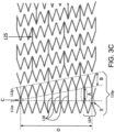
- the lengths of closed cell connectors 118 vary. As depicted, the lengths of the closed cell connectors 118 can increase uniformly along a circumferential direction of the stent from the closed cell connector 118 at region C, which can have lengths of about 0.3 mm to about 3.0 mm, and a width about the same as the width of the axial connector 125 (see Table 1). On the other hand, the closed cell connector 118 at region A can have the same or substantially the same length as the amplitude B of each undulation 107 in the helical turn 112p of the circumferential member 11 0p. Region E defines a notch 119 as shown in FIG. 3A .
- the lengths of the closed cell connectors 118 can adjusted so that one or more of the circumferential rings 111p (or 111d as shown in FIG. 3B ) at the end of the stent define a plane orthogonal to the longitudinal axis.
- the closed cell connectors 118 and axial connectors 125 of FIGs. 3A and 3B are depicted extending substantially parallel to the longitudinal axis 102 of the stent body 101.
- the closed cell connectors 118, axial connectors 125, or both need not be parallel to the longitudinal axis and can extend in a direction to the longitudinal axis at any angle (such as between about -90° and about 90° from the longitudinal axis), or may not even be substantially straight.
- the closed cell connectors 118 can extend substantially parallel to the longitudinal axis 102, while the axial connectors 125 form an angle to the longitudinal axis 102 of the stent body 101.
- the axial connectors 125 can extend substantially parallel to the longitudinal axis 102, while the closed cell connectors 118 form an angle to the longitudinal axis 102 of the stent body 101. Further still, the closed cell connectors 118 can be bent, for example roughly in the shape of the letter V or can include one or more curved portions.
- the circumferential members 110p and 110d have closed cells 104 in the stent shown in FIGs. 3A and 3B .
- the closed cells can have six sides or less. A side may be straight or have curvature. As depicted, some of the closed cells have a substantially hexagonal shape, and others have a substantially rhombic shape. Other shapes or combinations of shapes are possible such as various regular or irregular shapes.
- an undulating circumferential ring 111p or 111d of the circumferential member 110p or 110d has a series of apices 114 in each undulation 107.
- An undulating helical turn 112p or 112d of the circumferential member 110p or 110d also has a series of apices 116 in each undulation 106.
- Closed cell connectors 118 extend between peaks 106' of the undulating helical turn 112p or 112d and peaks 107' of the adjacent undulating circumferential ring 111p or 111d at the proximal and distal ends of the stent 100, respectively.
- the closed cell connectors 118 within the undulating circumferential members 110p and 110d can extend from a valley to a valley, from a peak to a valley, or from a valley to a peak.
- the stent of FIGs. 3A and 3B also has open cells 105.
- the open cells 105 can have seven sides or more.
- Axial connectors 125 extend intermittently between longitudinally adjacent turns of the undulating helical element 120. These axial connectors 125 join pairs undulations 106 on the adjacent turns [112p-121p, 121p-122 ... 122-121d, and 121d-112d].
- the shape of the open cells depicted in these figures is exemplary.
- the open cells shown in FIGs. 3A and 3B are defined by regular, intermittent axial connectors 125.
- the open cells can be formed by irregular, intermittent axial connectors.
- FIGs. 3A and 3 B further illustrate direct connections between the helical element 120 and the circumferential members 110p and 110d.
- the undulating helical element 120 has a series of helical turns [121p, 121d, 122, etc] about the longitudinal axis 102.
- the circumferential member 110p or 110d also has an undulating helical turn 112p or 112d.
- the undulations 106 of the helical turn 121p or 121d of the undulating helical element 120 form continuous helical pattern with the undulations 106 of the undulating helical turn 112p or 112d of the circumferential member 110p or 110d without any intermediate or transition stages in-between.
- Such continuous helical pattern defines a direct connection between the helical element 120 and the circumferential members 110p and 110d.
- FIGs. 3A and 3B also illustrate apex geometry.
- Apex geometry refers to configuration of the apices 114, 116, 123 where two or more struts 115, 117, 124 meet, respectively.
- Each strut and each apex has a cross-section with a width, and a thickness (into the page).
- Apex radius, width, and thickness (see FIGs. 4A-4C ), and the angles of the struts forming those apices substantially define the apex geometry.
- the undulating helical turn 112p or 112d of the circumferential member 110p or 110d and the helical turns 121p, 121d, 122 of the helical element 120 have a substantially uniform apex geometry.
- the circumferential ring 111p or 111d also has the same apex geometry as the undulating helical turn 112p or 112d of the circumferential member 110p or 110d and the helical turns 121p, 121d, 122 of the helical element 120. It is also possible for the apex geometry to be varied. For example, the circumferential ring 111p or 111d, undulating helical turn 112p or 112d of the circumferential member 110p or 110d and the helical turns 121p, 121d, 122 of the helical element 120 can each have different apex geometries.
- the circumferential members 110p and 110d have at least two undulating structures.
- the circumferential members 110p and 110d are depicted with one undulating helical turn 112p or 112d and an undulating circumferential ring 111p or 111d.
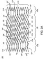
- the circumferential member 110p or 110d of FIG. 2A has the same number apices in the undulating helical turn 112p or 112d and the circumferential ring 111p or 111d.
- the amplitudes of the undulating helical turn 112p or 112d and the circumferential ring 111p or 111d are substantially the same. It is possible, however, that the circumferential ring 111p or 111d can have a greater or lesser number of apices than the helical turn 112p or 112d.
- the circumferential ring 111p or 111d can have a greater or lesser amplitude than the helical turn 112p or 112d.
- the circumferential members 110p and 110d at the distal and proximal ends of the stent that can define a plane orthogonal to the longitudinal axis 102.
- the circumferential rings define a plane orthogonal to the longitudinal axis 102 when the circumferential member 110p or 110d includes a circumferential ring 111p or 111d and a helical turn 112p or 112d.
- the ends of the stent can define other angles with respect to the longitudinal axis.
- One or more of the circumferential members 110p or 110d can be flared. That is, a diameter at an end of the stent 100 is greater than a diameter defined at the direct connection of the circumferential member 110p or 110d and the helical element 120.
- circumferential members 110p and 110d at both ends of the stent can be flared.
- apices of the circumferential ring 111p or 111d can be out of phase with apices of the helical turn 112p or 112d by about a half of wave period and the number of apices is equal. This can provide, for example, a peak to valley arrangement of apices in the circumferential member 110p or 110d.
- the helical turns of the helical element and the undulated helical turn of circumferential member can have constant and identical amplitude throughout the winding of the helical body of the stent.
- the lengths of the closed cell connectors 118 vary.
- the lengths of the closed cell connectors 118 can uniformly increase along a circumferential direction of stent.
- the lengths of closed cell connectors 118 need not uniformly increase.
- the closed cell connectors 118 can be placed at various locations between the undulations 107 of the helical turn 112p or 112d and the circumferential ring 111p or 111d, which will vary their lengths accordingly.
- the widths of the closed cell connectors 118 can be varied. For example, in FIGs. 3A and 3B , the widths of all but one of the closed connectors are substantially the same.
- the shortest of the closed cell connectors joins two struts 115 that form the apex 114 of the circumferential ring 111p or 111d, and the last strut 117 of the apex 116 of the helical turn 112p or 112d. That closed cell connector can have a greater width than the other closed cell connectors 118, and can, for example, have a width approximately twice that of the other closed cell connectors.
- Individual closed cell connectors 118 also can have variable widths.
- the shortest closed cell connector 118 has a variable width.
- a portion of the length of that closed cell connector can be narrowed to provide a notch 119.
- the shown notch is directly adjacent to the apex of the adjoining circumferential ring 111p or 111d and can have length and width that is approximately equal to the width of apex junction as shown in FIG. 4A , although these parameters can also be varied beyond the width of the apex junction.
- That notch can be provided anywhere along the length of that closed cell connector, however.
- the notch can act as a hinge and facilitate bending at that point, or can reduce stresses and strains around the area when the stent is deformed.
- bending or stress/strain relief can be facilitated by other means, such as by varying the thickness of the strut locally at that point.
- Exemplary dimensions of aspects of the circumferential ring are shown in Table 1 below. Table 1 - Exemplary Closed Cell Connector Dimensions Measurement Approximate Dimension (millimeters) Length (shortest closed cell connector) 0.4 Length (longest closed cell connector) 3.0 Incremental Length Increase (closed cell connector) 0.3 Width (closed cell connector) 0.1 Length (notch) 0.4 Width (notch) 0.1
- the lengths and widths of the axial connectors 125 are shown to be substantially uniform throughout the stent.
- the lengths and widths of axial connectors 125 can vary.
- the axial connectors 125 can be placed at various locations between the undulations 106 of the adjacent helical turns, which will vary their lengths.
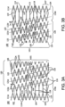
- the number of axial connectors 125 in the stent is variable. Two to six axial connectors are provided per helical turn, with a ratio of about 2.5 to 2.75 axial connectors per helical turn is shown in FIGs. 2A , 2B .
- the axial connectors 125 can be connected between adjacent apices of the undulating helical turns.
- the axial connectors 125 in one helical turn pair, 121p-122 can be offset from the axial connectors 125 in the immediately adjacent helical turn pair.
- the placement of axial connectors, while offset in the immediately preceding and/or following helical turn pairs, can remain in the same longitudinal arrangement in the alternating pairs (see FIGs. 2A and 2B ), every second helical turn pair.
- the axial connectors 125 have a specific offset arrangement.
- the axial connectors 125 in the immediately adjacent helical turn pair can have the same offset arrangement.
- the arrangement maintains the axial bending flexibility of the stent in virtually all directions.
- Other axial connector placements are also envisioned.
- the axial connectors 125 extend between peaks and valleys. Between about two and six axial connectors 125 can be provided per helical turn to maintain flexibility.
- the placement of the axial connectors 125 in the stent body 101 can be varied from distal to proximal end (left to right in FIG. 2A or 3A ). For example, some of the axial connectors 125 can be offset by about half an undulation period as compared to other of the axial connectors 125 of the stent body 101. This can help to avoid numerous four-strut junctions between the helical element 120 and the circumferential member 110d and to maintain the axial bending flexibility of the stent in virtually all directions.
- the exemplary stent 100 defines the circumference of the stent body 101 by 10 distal facing apices ("10-apices") or, as illustrated in FIGs. 6A and 6B , by 11 distal facing apices ("11-apices").
- a smaller diameter stent can be a "10-apices” design with a deployed diameter of about 5 to 8 mm.
- a stent can have an undulating helical element 120 that comprises about one helical turn or a portion of one helical turn such as about 4 5 , 3 ⁇ 4, or 1 ⁇ 2 of a helical turn. An example of such a stent is shown in FIG. 9 .
- the stent can have a deployed diameter of about 3 mm to about 6 mm, including about 3 mm, 3.5 mm, 4 mm, 4.5 mm, 5 mm, 5.5 mm, and 6 mm.
- a stent can have a length of about 15 mm and an insertion, pre-deployed diameter of about 1.0 mm to about 2.3 mm.
- a larger stent can be an "11-apices" design with a deployed diameter of about 9 to 10 mm. However, 6-, 8-, 9-, 12-, 13-, 14-, 15-, 16-, 18- and more apices are also envisioned and encompassed.
- the number of closed cell connectors 118 depends on the number of apices in the stent body. In FIGs. 2A and 2B , there are ten closed cell connectors 118. In FIGs. 6A and 6B , there are eleven closed cell connectors 118. Increasing the number of closed cell connectors can increase the axial stiffness and columnar strength of the distal and proximal undulating circumferential members at the ends of the stent 100. This can decrease the overall tendency for the stent 100 migration along the vessel lumen and further reduces, for example, the tendency of the stent to either move into the site of the aneurysm or follow the path of the expanded vessel.
- the closed cell and axial connectors 118, 125 have a tendency to maintain axial spacing of the helical turns at their connection points, act as springs in this situation, store mechanical energy which then acts to restore the stent to an unbuckled state.
- Table 2 Exemplary dimensions of aspects of the undulating helical element are shown in Table 2 below: Table 2 - Exemplary Undulating Helical Element Dimensions Measurement Approximate Dimension (millimeters) Length (short strut) 2.6 Length (long strut) 2.9 Strut Width 0.1 Length (axial connector) 3.1 Width (axial connector) 0.1 Radius (apex) 0.2 Width (apex) 0.2
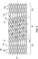
- FIG. 5 shows a variation of the circumferential members.
- the circumferential member is provided with additional circumferential rings 113p or 113d at the ends.
- additional circumferential rings are shown as 113p and 113d.
- the number of circumferential rings 111p and 113p, or 111d and 113d at the distal and proximal ends can be the same or different.
- the stent 100 can be formed from a wide variety of materials or combinations of materials, including metals and plastics.
- metals that can be used are stainless steel, titanium, tantalum, alloys such as Elgiloy ® and Phynox ® spring alloys, 316 stainless steel, MP35N ® alloy, and Nitinol nickel-titanium alloy.
- super-elastic versions or shape memory versions of the mentioned alloys can also be used.
- Use of nitinol alloys can impart the self-expanding characteristic to the stent.
- the phase behavior of the material can be selected and the stent treated so that the stent has a tendency to transform from the insertion configuration to deployed configuration when unconstrained at body temperature.
- the active A f (austenitic transformation finish) temperature for nitinol of the completed stent assembly can be less than about 35 °C, be between about 0 °C and about 25 °C, or be between about 10 °C and about 17 °C, as determined by a bend and free recovery test known in the art (see ASTM standard no. F2028-01).
- plastics useful for fabricating the stents are PTFE, other fluoropolymers, or other plastics (such as PET).
- resorbable materials polymers or copolymers possessing one or more of the following monomeric components: glycolide (glycolic acid); lactide (d-lactide, l-lactide, d,l-lactide); trimethylene carbonate; p-dioxanone; caprolactone, hydroxybutyrate, hydroxyvalerate. These identified materials are exemplary and any material suitable for implantation can be used.
- the stents can be cut from a continuous tube of material into the desired pattern, such as through use of a laser.
- the stents can also be constructed by various known techniques such as machining, chemical etching, laser ablation, die-cutting, plasma etching, stamping, water jet cutting or any other suitable means as long as the required stent structure can be achieved.
- the stents can also be formed from a flat sheet of material that is cut into the desired pattern and then bonded together to form a tube having a seam.
- the stents can be constructed from wires or ribbons that are formed into the desired shapes and then bonded together, for example by welding, into the final pattern.
- Coverings can be provided for the stent.
- the use of coverings in combination with the stent can help, for example, to (1) minimize or at least reduce the risk of introduction of emboli into a bloodstream, (2) resist tissue encroachment into the lumen defined by the stent, and (3) reduce pressure on a weakened part of a blood vessel to reduce the risk of vessel rupture.
- Coverings can be made from continuous materials with no holes visible without magnification.
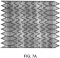
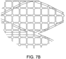
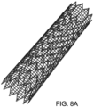
- FIGs. 7A and 7C illustrate two kinds of other coverings, which can be termed to be lattices. These lattices are unitary structures. A series of interconnected, continuous segments define one or more patterns of openings in the lattice. The width of the lattice segments ranges between about 0.02 mm and about 0.2 mm, between about 0.02 mm and about 0.1 mm, or about 0.05 mm. The thickness of the lattice segments ranges between about 0.02 mm and about 0.2 mm, between about 0.02 mm and about 0.1 mm, or about 0.05 mm.
- the lattice opening size is the diameter of the largest inscribed circle, and ranges between about 40 ⁇ m and about 1 mm, between about 50 ⁇ m and about 800 ⁇ m, between about 100 ⁇ m and about 750 ⁇ m, or between about 200 ⁇ m and about 500 ⁇ m.
- the lattice opening size can be the size of the smallest kerf width of a laser.
- a lattice opening for use in an application such as aneurysm exclusion can be between about 10 ⁇ m and about 40 ⁇ m, between about 12 ⁇ m and about 30 ⁇ m, or between about 15 ⁇ m and about 20 ⁇ m.
- the lattice openings can be arranged in various regular and irregular patterns to provide diametrically stable functionality.
- the openings can have various shapes, such as triangles, squares, diamonds, parallelograms, hexagons, circles, or any other geometric shape, or combinations of shapes.
- FIGs. 7A and 7C show illustrative square and diamond-shaped openings, respectively.
- the square-shaped lattice of FIG. 7A has a series of continuous longitudinal segments that extend in a direction that is substantially parallel to a longitudinal axis of the stent, and a series of continuous circumferential segments that extend in a direction that is at an angle approximately transverse to the longitudinal axis of the stent.
- the square-shaped openings have four equal or substantially equal sides and its interior angles are all at or approximately right angles (90°).
- the arrangement of the square-shaped lattice of FIG. 7A can provide longitudinal segments with substantially constant length in an insertion or constrained configuration (when the stent has a reduced profile), and in a deployed configuration (when the stent has an enlarged profile greater than the insertion profile).
- the longitudinal segments of the lattice can have lengths ⁇ 5% in the insertion configuration, ⁇ 4% in the insertion configuration or ⁇ 2% in the insertion configuration.
- the lattice covering can have parallelogram-shaped openings.
- Continuous longitudinal segments extend in a direction that is substantially parallel to the longitudinal axis of the stent.
- Continuous circumferential segments extend at an angle with respect to the longitudinal axis that is greater than 0° and less than about 90° with respect to the longitudinal axis.
- the circumferential segments can be oriented at an angle of about 45° with respect to the longitudinal axis.
- Such a parallelogram-shaped lattice can be positioned with respect to the stent so that one or more of the longitudinal segments extend along the length of the closed cell connectors.
- the lattice covering can have diamond-shaped openings as shown in FIG. 7C .
- Two sets of continuous circumferential segments extend at different angles with respect to the longitudinal axis of the stent. For example, a first set of the circumferential segments is oriented at an angle of about 45° with respect to the longitudinal axis, while a second set of the circumferential segments is oriented at an angle of about -45° and about -90° with respect to the longitudinal axis. In the lattice depicted in FIG. 7C , there are no longitudinal segments.
- the lattice can have two sets of circumferential segments, as well as longitudinal segments.
- One set of the circumferential segments can be oriented at an angle of between about 45° and about 90° with respect to the longitudinal axis, while a second set of the circumferential segments can be oriented at an angle of between about -45° and about -90° with respect to the longitudinal axis.
- Longitudinal and/or circumferential lattice segments can be positioned to extend along one or more stent struts.
- longitudinal segments of the square-shaped openings extend along one of the closed cell connectors of the circumferential member, and are longitudinally aligned with it.
- the number of longitudinal segments of the lattice covering can be the same as or greater than the number of the closed cell connectors in each of the circumferential members.
- One, some, or all of the longitudinal members can be joined with the closed cell connectors.
- other shaped openings of the lattice can be aligned so that one or more sides extend along the length of one or more connector struts within the stent.
- the number of attachments between the stent and the lattice covering can be varied depending on various factors, such as the size of the stent openings, the size of the lattice openings, and the orientation of the lattice with respect to the stent.
- the closed cells 130 of the stent have a larger dimension along the longitudinal axis, and a shorter dimension transverse to the longitudinal axis.
- the square-shaped lattice covering is oriented with fewer lattice openings across the larger dimension of the closed cell 130, and an equal or fewer lattice openings across the smaller dimension of the closed cell 131.
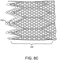
- the diamond-shaped lattice covering is oriented with more lattice openings across the smaller dimension of the closed cell (133) than in FIG. 8B .
- FIGs. 7A , 7B and 7C A substantially uniform lattice opening pattern is shown in FIGs. 7A , 7B and 7C .
- the size and shape of the openings is substantially uniform throughout.
- the lattice opening pattern also can be irregular.
- Lattice openings can be provided in one portion and not in the balance of the lattice.
- a first arc of the lattice can have openings along the entire length of the lattice while a second arc opposite of the first arc is substantially without openings.
- the lattice openings can be provided in along a spiral with respect to the longitudinal axis.
- the lattice can have a perfusion region within which the openings are provided and an excluding region devoid of openings, thus, configured to allow orientation of the perfusion region to be determined endovascularly.
- the lattice openings can have several patterns.
- the openings of similar size and shape can be grouped together to have at least two sets of openings with each set having a predetermined size and shape, or uniformly distributed throughout the lattice.
- lattice openings corresponding to the circumferential members can be square-shaped as depicted in FIG. 7A
- the lattice openings corresponding to the helical element can be diamond-shaped as depicted in FIG. 7C .
- the lattice can have three sets of openings distributed along the length of the lattice, one at the proximal end, one at the distal end and one in-between.
- the openings of the proximal set for example, can have diamond-shaped openings with a nominal diameter of about 300 ⁇ m as measured by the largest inscribed circle.
- the openings of the distal set for example, can also have diamond-shaped openings but with a nominal diameter of about 500 ⁇ m as measured by the largest inscribed circle.
- the openings of the central set those that span between the proximal and distal sets, can have squared-shaped openings with a nominal diameter of about 100 ⁇ m as measured by the largest inscribed circle.
- Other permutations, sets, and groupings are also envisioned.
- one or more large oval openings adapted to allow for side branch perfusion can be provided.
- the lattice can be produced by laser cutting, such as a CO 2 laser, from a longitudinally wrapped tube of, for example, six layers of biaxially-oriented film made from one suitable cover material or from a combination of suitable cover materials to produce a unitary structure, not woven.
- a lattice could have a nominal thickness between about 10 ⁇ m and about 250 ⁇ m, between about 20 ⁇ m and about 60 ⁇ m, or between about 35 m and about 50 ⁇ m.
- Other films can be used together with the biaxially-oriented films or in place of them to form the lattice.
- uniaxially-oriented or multiaxially-oriented films can be used. These films can be wrapped longitudinally as described above, or can be wrapped in other configurations.
- the films can be helically wound to form the tubular structure.
- Other methods of lattice preparation are also envisioned in accordance with the procedures described in U.S. Pat. Pub. No. 2008/0119943 to Armstrong et al., or U.S. Pat. 7,306,729 to Bacino et al. , the entire disclosures of which are incorporated herein by reference.
- Perforated covers were created by initially wrapping several layers of an ePTFE film that includes a discontinuous (porous) layer of FEP. Films made as taught by U.S. Pat. No. 5,476,589 to Bacino are suitable for FEP coating and use in this application.
- the film used ranged from 2.5 to 5 microns in thickness and had a density range of about 0.5 to 1.0 g/cc.
- the film was wrapped circumferentially, with the FEP side oriented outwards, onto a glass mandrel approximately 1 mm diameter larger than the outside stent diameter.
- Other materials, including biocompatible polymers and metals could be used for the perforated cover structure, with process parameters adjusted accordingly. Twelve layers of the film were wrapped around the mandrel surface, with a range of 2 to 100 layers considered desirable.
- the wrapped mandrel was placed in a convection oven set at 320 °C for 12 minutes, and then allowed to cool to about ambient temperature. While the perforations may be formed by various methods including the use of, for example, mechanical punches, laser cutting is preferred for speed and precision.
- a lattice can also be formed from a fiber by techniques such a knitting, weaving, or crocheting.
- Conformability of the stent with and without the lattice can be measured according various known test methods.
- ISO 25539-2 (2008) describes one protocol for assessing the ability of medical devices to conform to vessel walls and is incorporated in and constitutes a part of this specification.
- the test method measures the smallest radius of curvature that a stent can withstand without kinking. A more conformable stent will have greater ability to conform to bends having a smaller radius of curvature without kinking, and a less conformable stent will have a lesser ability to conform to such bends without kinking.
- Flexibility of the stent with and without the lattice can be assessed by a three-point bend test on deployed stents.
- One method for such testing is set forth in ASTM F2606-08, the entire disclosure of which is incorporated herein by reference. Most generally, after the stent is placed into a specific three-point bend fixture, the amount of force required to bend the stent is measured. The resulting load-deflection curves can be used to assess flexibility of stents. A more flexible stent will have greater ability to bend at lower forces, and a less flexible stent will have a lesser ability to bend at lower forces.
- the stent and the lattice can be sized to be the same or different.
- the lattice covering shown in FIGs. 7A , 7C , 8A and 8B does not notably constrain the stent, and for example, the stent has an outer diameter of about 8 mm, and the lattice has an inner diameter of about 8 mm.
- the lattice can resist full expansion of the stent, depending upon lattice geometry and material chosen. This can be achieved by oversizing the stent with respect to the lattice covering.
- the stent can have an outer diameter that is oversized with respect to the lattice covering in an amount of about 10% to about 100%, between about 20% and about 70%, or between 30% and about 50%.
- the self-expanding stent can have an outer diameter of about 10 mm, and the lattice can have an inner diameter of about 8 mm.
- An effect of oversizing the stent as compared to the lattice is to provide a final self-expanding device that resists forces tending to collapse the deployed stent.
- the amount of force needed to reduce the diameter of the deployed stent is higher when an oversized self-expanding stent is used as compared with the same stent that is not oversized.
- the lattice can be made from a distensible material.
- a distensible material for the lattice can be made according to various known techniques, such as in accordance with the procedures described in U.S. Pat. Nos. 4,877,661 and 5,026,513 to House et al. , the entire disclosures of which are incorporated herein by reference. Using this method, a liquid lubricant is mixed with a commercially available powder of PTFE, and the mixture is extruded by a ram-type extruder or other type of extruder.
- the material is then expanded by rapid stretching either uniaxially, biaxially, or multiaxially after the liquid lubricant is removed from it.
- the material after stretching is then heated while restrained to a temperature above its crystalline melt point of the polymer and held there for a period of time.
- the time and temperature will vary depending on the amount of material being heated. In general, the higher the temperature used, the shorter the time.
- a strong porous material is produced.
- This material having undergone uniaxial expansion has a microstructure of nodes interconnected by fibrils that are essentially parallel and straight.
- the lattice made from distensible material can have a rapid recovery of greater than about 5.5%, greater than about 15%, or greater than about 30%.
- the stent can be sized to have an outer diameter of about 8 mm, and the distensible lattice can be sized to have an inner diameter of about 6 mm.
- FIG. 11A is a partial view of a lattice covering prior to micro-catheter advancement.
- FIG 11B is a partial view of the lattice with a micro-catheter advancing through one of the lattice openings and showing the opening deforming to take the shape of the outer diameter of the micro-catheter.
- FIG 11C is a partial view of the same lattice in FIG 11B after the micro-catheter is removed and shows that the lattice opening has substantially returned to its original size and shape. The lattice would substantially return to its structure, size and shape once the side branch or additional device is deployed and that deployment system removed from the lattice.
- a lattice covering can be formed from longitudinal strips of any of the cover materials described herein including by bonding or weaving into a basket weave, mesh, or lattice pattern.
- a stent can be covered with multiple layers of coverings.
- a lattice can be formed by two or more layers of lattice coverings. Two or more layers can be bonded together with openings aligned or offset. One or more of the layers can have elastic properties.
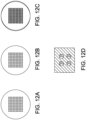
- Two lattice coverings as shown in Figures 12A and 12B can be layered such that the openings are offset or staggered as shown in FIG. 12C .
- the resulting open area, as shown in FIG. 2D, may provide smaller trans-mural porosity than may be achieved by utilizing a single lattice covering.
- a lattice can be imbibed with PVA (polyvinyl alcohol) or other materials (e.g., gold, platinum/iridium, or the like) to aid the physician during imaging (e.g., ultrasound, fluoroscopy, MRI, or the like).
- a lattice can be imbibed with one or more therapeutic agents.
- the term "imbibed or imbibing" as used herein is meant to describe any means for at least partially filling a portion of the pores of a porous material such as ePTFE or the like. This can be done during manufacturing by, for example imbibing, or it can be done during catheter flushing which may imbibe or coat one or more therapeutic agents into or onto the lattice.
- a therapeutic agent can be a drug or other pharmaceutical product such as a non-genetic agents, genetic agents, cellular material, etc.
- suitable non-genetic therapeutic agents include but are not limited to: anti-thrombogenic agents such as heparin, heparin derivatives, vascular cell growth promoters, growth factor inhibitors, paclitaxel, etc.
- an agent includes a genetic therapeutic agent
- such a genetic agent may include but is not limited to: DNA, RNA and their respective derivatives and/or components: hedgehog proteins, etc.
- a therapeutic agent includes a cellular material
- the cellular material may include but is not limited to: cells of human origin and/or non-human origin as well as their respective components and/or derivatives thereof.
- the therapeutic agent includes a polymer agent
- the polymer agent may be a polystyrene-polyisobutylene-polystyrene triblock copolymer (SIBS), polyethylene oxide, silicone rubber and/or any other suitable substrate.
- SIBS polystyrene-polyisobutylene-polystyrene triblock copolymer
- the polymer agent can be biodegradable such as PLA, PLGA, etc.
- a therapeutic agent can also be a coating material as described herein.
- a lattice can also be imbibed with an alginate.
- the alginate can be imbibed throughout the lattice or selectively to one or more portions of the lattice.
- the alginate can be cross-linked by delivering divalent or trivalent cations (for example, calcium) though a catheter or the stent delivery system to the stent delivery site.
- the cross-linked alginate portion of the lattice can be used to relieve pressure from weakened portions of a blood vessel (for example, to treat a cerebral aneurysm) or to occlude other openings or vessels adjacent to the sidewall of the stent.
- a lattice can be imbibed with calcium.
- An alginate can be delivered to the calcium imbibed lattice through the stent delivery system or by another catheter system to cause crosslinking on or in close proximity to the lattice.
- a stent with a calcium imbibed lattice can be placed over an aneurysm neck and then one can introduce the alginate through the lattice and into the aneurysm. While flowing through the calcium imbibed lattice, the alginate can react with the calcium to cause formation of a gel in the aneurysm sac.
- the lattice is shown to be generally uniform.
- the lattice covering can be varied along its length.
- the size of the openings, the orientation of the openings and their shapes need not be uniform throughout the lattice covering.
- a portion of the lattice covering can have square-shaped openings and another portion of the lattice covering can have diamond-shaped openings.
- coverings can be joined to the stent over all or over only a portion of the device length.
- the coverings can be joined intermittently.
- a lattice covering can be joined only at the ends of the stent, at the closed cell portions of the stent, or only at the closed cell connectors.
- the covering can be on the outside of the stent elements; it can be on the inside of the stent; or it can be on both.
- the attachment of the stent and the covering can be accomplished by mechanical means such as fiber, braiding a lattice into the stent, or discrete mechanical attachment points (clips, etc.). These components also can be bonded together through heat treatment (such as, sintering of the materials together) or through use of a wrap (for instance a tube, tape, or membrane) around the outside of the stent and cover (either continuous or discontinuous), that is adhered through either a thermoplastic or thermoset adhesive to the stent and cover.
- the covering also can be attached to the stent by adhering the two together through use of a suitable adhesive. Combinations of these methods also can be used. These methods and combinations of these methods can be used to attach the stent and covering while under inert gas conditions as commonly known in the art.
- thermoplastic adhesives such as fluorinated ethylene propylene (FEP), polyurethane, cyanoacrylate, thermoplastic fluoropolymer, including flouroelastomers such as those disclosed in U.S. Pat. No. 7,049,380 [TFE/PMVE], etc.
- FEP fluorinated ethylene propylene
- polyurethane polyurethane
- cyanoacrylate thermoplastic fluoropolymer
- thermoplastic fluoropolymer including flouroelastomers such as those disclosed in U.S. Pat. No. 7,049,380 [TFE/PMVE], etc.
- Copolymer contains between about 40 and 80 weight percent perfluoromethyl vinyl ether and complementally 60 and 20 weight percent tetrafluoroethylene, wherein said copolymer contains fewer than about 50 parts per million by weight of fluorinated anionic surfactant.
- Thermoset adhesives are also useful, such as silicone including room temperature vulcanizing (RTV) silicone.
- the cover is a PTFE lattice
- fluorinated ethylene propylene (FEP) can be used as an adhesive.
- FEP fluorinated ethylene propylene
- Such a coating can be applied by various methods including extrusion over the covering, powder coating with powdered FEP that is subsequently melted to flow over the lattice surface, or running the covering through a bath of molten FEP optionally followed by pulling the covering through a die to achieve uniformity of the coating.
- the stent can be provided with a coating of adhesive such as by powder coating with FEP in a continuous or discontinuous fashion, or through use of an FEP wrap (for instance a tube, tape, or membrane).
- a cover can be provided that allows the stent to be embedded within the cover material, such as through use of a silicone or other elastomeric material.
- Covers can be coextensive with the length of the stent, as shown in FIGs. 7A-7C and 8A-8C, or they can be either longer or shorter than the stent. Covers can also cover only a portion of the stent, or can cover separately two or more portions of the stent. If multiple portions are covered, covers can also overlap on the stent.
- the stent, the covering or both can be provided with additional treatment or therapeutic agents, such a drugs, radiation, radiopaque markers or coatings, or other agents to enhance visualization in-vivo.
- additional treatment or therapeutic agents such as drugs, radiation, radiopaque markers or coatings, or other agents to enhance visualization in-vivo.
- various coatings can be provided on all or some of the stent surface, the covering or both.
- Suitable coating materials include fluoroelastomer, ceramic, silicone, polyethylene, carbon, gold, heparin, hydrogel, lubricious coatings, antibiotics, anticoagulant agents, anti-inflammatory agents, antimetabolic agents, antimicrobial agents, antimigratory agents, antiplatelet agents, antiproliferative agents, antisense agents, cytostatic agents, nitric oxide releasing agents, pro-endothelial agents, selective gene delivery vectors, super oxide dismutases, super oxide dismutases mimics, vasoactive agents, and combinations thereof, such as, for example, actinomycin-D, ciclosporin, clobetasol, dexamethasone, estradiol, everolimus, heparin, paclitaxel, pimecrolimus, rapamycin, sirolimus, tacrolimus, and derivatives of these compounds.
- Coating materials can provide numerous benefits, including protecting the underlying stent material, providing a substrate for delivery of drugs or other therapeutic substances, isolating the stent material from interaction with surrounding cells, improving fluoroscopic visualization. Coatings can be applied in any material-appropriate manner, such as dip-coating, spray-coating, electro-deposit, or chemical vapor deposition.
- Such a stent can be used to treat various body lumens, including, the aortoiliac, carotid, cerebral, coronary, hepatic, infrainguinal, mesenteric, renal, splenic, subclavian, and superior mesenteric arteries.
- Such a stent's configuration allows it to conform to the native anatomy of blood vessels or other body lumens, while also enhancing the stent's fatigue performance and crush-resistance.
- a stent as described herein can be used for treating stenosis in a carotid artery of a patient.
- a stent is provided having an insertion configuration with a reduced profile and a deployed configuration with an enlarged profile greater than the insertion profile.
- the stent can be a nitinol stent which is capable of self-expanding to the deployed configuration when a constraint is removed.
- the stent has at least two spaced apart, undulating circumferential members, and an undulating helical element extending helically about the longitudinal axis, axially interposed between and directly connected to the circumferential members.
- the undulating helical element defines a plurality of open cells, and the circumferential member defines a plurality of closed cells.
- the stent is inserted into the vasculature of the patient. The stent is then positioned and deployed within the patient's carotid artery, for example, at a position where plaque has caused a narrowing of the artery.
- the stent can be delivered by catheter.
- the stent can be radially compressed and placed within a sheath.
- the sheath can be subsequently mounted on a 5F (for 6-8 mm) or 6F (for 9-10 mm) introducer-sheath compatible delivery system.
- one or more radiopaque markers can be integrated into the delivery system.
- one radiopaque marker such as BaSO 4
- Another radiopaque marker such as a platinum / iridium band, can be incorporated into the sheath material to indicate progression of the sheath retraction during stent deployment.
- two markers such as gold, platinum, or tantalum, can be placed adjacent to the proximal and distal ends of the compressed stent to aid in positioning.
- Exemplary deployment systems that can be used in conjunction with the stents discloses herein include U.S. Pat. Nos. 6,139,572 ; 6,352,561 and 7,198,636 which are incorporated by reference herein.
- the system comprises a guidewire having a hollow, bullet-shaped distal end, a balloon catheter and separate inflation means for the balloon catheter and for deployment of an intraluminal graft.
- Deployment as used herein describes the process of causing an intraluminal graft to fit coaxially in close contact with the luminal surface of the conduit within which the graft has been placed, with little or no wrinkling of the intraluminal graft. Deployment may involve the circumferential distension of the graft or may involve unfolding of a graft previously folded into a compact volume for insertion.
- the hollow, bullet-shaped distal end encloses the balloon and the distal end of the intraluminal graft, allowing for easy insertion of the delivery system into the vascular system.
- the guidewire is located within a lumen of the catheter shaft of the balloon catheter to allow axial movement of the hollow, bullet-shaped end with respect to the balloon and the intraluminal graft.
- Balloon inflation means such as a syringe is fitted to the proximal end of the balloon catheter to accomplish inflation of the balloon located at the distal end.
- Separate inflation means such as a second syringe is provided for deployment of the intraluminal graft.
- the delivery system is inserted further into the vascular system until the desired location for the intraluminal graft is reached, which may be verified by conventional imaging techniques such as angiography in that portions of the system may be made to be radiopaque.
- the hollow, bullet-shaped tip is extended distally beyond the balloon by axial movement of the guidewire, after which the balloon is inflated causing deployment of the distal end of the intraluminal graft.
- the balloon is adequately inflated to cause the end of the intraluminal graft to be secured against the lumen of the conduit in which it is located and thereby sealed to the lumen.
- the intraluminal graft is then held captive between the balloon at the distal end and its attachment to a seal fitting located at the proximal end of the graft.
- the means for deploying the intraluminal graft is then activated, introducing a volume of an inflating medium, preferably a liquid such as saline into the interior of the tubular intraluminal graft between its ends adequate to cause deployment of the intraluminal graft, thereby bringing it into contact with the lumen of the living vessel.
- the pressure within both the balloon and the intraluminal graft is then released, leaving the intraluminal graft deployed outwardly against the lumen of the conduit.
- the proximal end of the intraluminal graft is transected even with the transected end of the conduit.
- the hollow, bullet-shaped end is moved in a proximal direction to enclose the deflated balloon, after which the delivery system is withdrawn leaving the intraluminal graft behind.
- the proximal end and optionally the distal end of the intraluminal graft are then secured using sutures if such an attachment is desired.
- the proximal end and optionally the distal end of the intraluminal graft may be secured using expandable stents, which offer the advantage of accomplishing attachment of the intraluminal graft via transluminal placement.
- An attaching stent may be deployed during inflation of the balloon portion of the delivery system, or alternatively may be separately deployed to attach the intraluminal graft subsequent to its delivery and deployment.
- the system generally comprises a sheet of material adapted to extend around at least a portion of a collapsed implant, such as a collapsed stent or stent-graft.
- the sheet of material may form a tubular member when extending around at least a portion of a collapsed member.
- the system also may include a coupling member for coupling portions of the sheet together to maintain the implant in its collapsed state during delivery to a desired site in a mammalian body. With this construction a smooth interface between the collapsed stent and a vessel lumen, as compared to thread-like restraining members, may be achieved.
- the sheet may be constructed of a thin material which does not significantly contribute to the structural rigidity or cross-sectional profile to the delivery assembly.
- This construction may also eliminate the need for external sheathing or a guide catheter and is believed to advantageously increase the ability of the surgeon to deliver the device to relatively remote sites and through small tortuous vasculature.
- the sheet may comprise implantable material so that after release it may remain with the stent at the desired site.
- the deployment system includes a confining sheath placed around a compacted endoluminal device.
- a deployment line is provided in the system that is an integral extension of the sheath.
- the sheath retracts from around the compacted endoluminal device.
- material from the sheath may be converted into deployment line.
- the endoluminal device expands in configuration and repairs vascular or cardiac structures of an implant recipient. Any remaining sheath material is removed from the implantation site along with the deployment line.
- Alternate deployment systems can be adapted for access in arteries or veins above the pelvis; for example, from the radial, brachial, and common carotid arteries.
- the access site arteries listed above are close to the carotid bifurcation and an alternate delivery system as shown in Fig. 10 can be used.
- the stent can be compressed and mounted on a delivery system as described previously.
- the common carotid artery can be punctured at a location just above the collarbone. In this instance, the distance from the puncture site to the carotid bifurcation is less than 20 cm.
- a conventional carotid stent delivery system in this instance would leave a significant length of redundant catheter thus necessitating the use of an assistant to stabilize and deploy the stent.
- An alternate deployment system can allow a single operator. Any stent can be delivered with such a delivery system.
- An example of a stent that can be delivered with such a delivery system would be a self-expanding stent including stents described herein, stents having a high radial force upon delivery, stents with a small circular cell size between expanded metal struts, and/or stents designed to be deployed to a heavily calcified region of vasculature.
- a delivery system adapted for access from the radial, brachial and carotid arteries can range from about 15 cm to about 80 cm in length and can be no longer than about 45 cm (or about 60cm or about 30cm or about 20 cm) for ease of use and operation by one operator.
- a delivery system can have a handle housing 300, a locking mechanism 302, flushing port 304, strain relief 306, catheter shaft 308, retractable sheath 310 covering stent, and a mechanism for operation of the deployment such as a thumb wheel 312.
- a cover can provide a scaffold to reduce the risk of introduction of emboli being released into a bloodstream.
- a cover also can resist tissue encouragement into the lumen defined by the stent.
- a cover can help to reduce pressure on a weakened part of a blood vessel, which in turn can reduce the risk of vessel rupture.
- the stent with a lattice can be useful for treating carotid stenosis.
- the lattice covered stent retains its flexibility and conforms to the anatomy, yet retains plaque due to a substantially smaller effective opening size of the lattice (as small as 0.04 mm).
- a stent is provided as described above having at least two spaced apart, undulating circumferential members, and an undulating helical element extending helically about the longitudinal axis, axially interposed between and directly connected to the circumferential members.
- the undulating helical element defines a plurality of open cells, and the circumferential member defines a plurality of closed cells.
- the stent is inserted into the patient while the stent is in an insertion configuration with a reduced profile.
- the stent is moved through the patients vasculature and positioned with the portion of the carotid artery to be treated.
- the stent is deployed so that it assumes an enlarged profile greater than the insertion profile.
- the stent can include a lattice covering to provide further emboli protection.
- the stent and lattice are configured and positioned after deployment so that the stent provides scaffolding necessary to hold the artery open and ensure adequate blood flow, while the lattice in combination with the stent simultaneously provides plaque stabilization.
- the lattice openings can further provide perfusion to a side branch vessel in this application when properly positioned.
- a lattice can have a perfusion region with openings and an excluding region substantially without the openings.
- the lattice covered stent can be positioned so that the perfusion region allows side branch perfusion. Orientation can be determined by fluoroscopic visualization of one or more radiopaque markers incorporated within the lattice.
- a lattice covered stent can be used in conjunction with balloon catheters and/or guidewires, for example, to provide perfusion to a side branch vessel.
- a balloon catheter can be endovascularly introduced into a one of the openings of the lattice, and expanded to distend or disrupt lattice covering. This allows endovascular modification of the size and shape of at least that one opening. Again, this can help to provide side branch perfusion among other uses.
- This self-expanding stent device is diametrically compacted at ambient temperature. Compaction is effected using a collet or iris type of diametrical compaction device, such as taught by U.S. Pat. No. 6,629,350 . The compacted stent device is inserted directly from the compaction device into a length of capture tubing to retain the stent device in its compacted state..
- a lattice of the type shown in FIGs. 7A and 8B with square-shaped openings is prepared.
- a mandrel is wrapped with an ePTFE film with a discontinuous FEP coating to a thickness of approximately 0.05 mm.
- the film-mandrel assembly is placed into an oven at 320 °C for 12 minutes to bond the layers.
- the assembly is removed from the oven and allowed to cool at room temperature to provide an ePTFE tube.
- Using a CO 2 laser a pattern of regular square openings is cut into the tube.
- the openings are square-shaped with a size of less than about 0.5 mm.
- the width of the lattice segments is greater than about 0.05 mm (see FIG. 7B ).
- the prepared square shaped lattice is placed in a convection oven set at 370 °C for 12 minutes.
- the material shrinks during heating to form squares that are approximately 0.5 mm diameter inscribed circle and lattice segments that are approximately 0.05 mm wide.
- a lattice of the type shown in FIGs. 7B and 8C with diamond-shaped openings is prepared.
- An oversized mandrel that is approximately 25% larger than the nominal stent diameter is wrapped with an ePTFE film with a discontinuous FEP coating to a thickness of approximately 0.05 mm.
- the film-mandrel assembly is placed into an oven at 320 °C for 12 minutes to bond the layers.
- the assembly is removed from the oven and allowed to cool at room temperature to provide an ePTFE tube.
- a pattern of slits approximately 40% longer than the final inscribed circle diameter are oriented transverse to the longitudinal axis of the mandrel are cut into the tube.
- the tube with slits is removed from the mandrel and stretched over the nominal stent diameter mandrel and the slits open to form diamond shapes.
- the tube ends are temporarily fixed to length on the mandrel by ePTFE tape.
- the assembly is then placed into a convection oven set at 370 °C for 12 minutes.
- the material shrinks to form diamonds that are approximately 0.5 mm diameter inscribed circle and lattice segments are approximately 0.05 mm wide.
- the obtained stent of Example 1 or 2 is powder coated with a thin layer of FEP powder (DuPont ® FEP Fluoropolymer Resin, Product Type 5101) in a tabletop blender within which the stent is suspended. After the stent is placed within the blender with FEP powder, the blender is activated. The powder disperses into the volume of the blender chamber and the stent is powder coated. After approximately 3 seconds, the stent is removed, and is placed into a convection oven set at 320 °C for 5 minutes. After this time, the stent is removed and allowed to air cool.
- FEP powder DuPont ® FEP Fluoropolymer Resin, Product Type 5101
- the stent is then placed on a mandrel having an outer diameter approximately equal to the inner diameter of the stent.
- the mandrel is covered on its outer diameter with polyimide film.
- the stent is placed in a convection oven set at 320 °C for 4 minutes.
- a square-shaped opening lattice according to Example 3 is coaxially positioned over the stent.
- the lattice is axially tensioned over the stent and comes in full contact with the outer diameter of the stent.
- the cover ends are temporarily fixed to length on the mandrel by ePTFE tape.
- a temporary layer of ePTFE film is then tightly wrapped around the assembly.
- the perforated cover is then placed within a convection oven set at 320 °C oven for 12 minutes to adhere the cover to the stent. After removal from the oven and being allowed to cool to ambient temperature, the temporary film wrapping is removed, and the stent and lattice covering are removed from the mandrel. The lattice is then trimmed flush with the end of the stent.
- the obtained stent of Example 1 or 2 is powder coated as described in Example 3 above.
- the prepared diamond-shaped opening lattice of Example 4 is coaxially positioned over the stent.
- the lattice is axially tensioned over the stent, causing it to decrease in diameter and to come in full contact with the outer diameter of the stent.
- the lattice ends are temporarily fixed to length on the mandrel by ePTFE tape.
- a temporary layer of ePTFE film is then tightly wrapped around the assembly.
- the lattice is then placed within a convection oven set at 320 °C oven for 12 minutes. After removal from the oven and being allowed to cool to ambient temperature, the temporary film wrapping is removed, and the stent and lattice covering are removed from the mandrel.
- the lattice is then trimmed flush with the end of the stent.
Landscapes
- Health & Medical Sciences (AREA)
- Engineering & Computer Science (AREA)
- Biomedical Technology (AREA)
- Cardiology (AREA)
- Oral & Maxillofacial Surgery (AREA)
- Transplantation (AREA)
- Heart & Thoracic Surgery (AREA)
- Vascular Medicine (AREA)
- Life Sciences & Earth Sciences (AREA)
- Animal Behavior & Ethology (AREA)
- General Health & Medical Sciences (AREA)
- Public Health (AREA)
- Veterinary Medicine (AREA)
- Gastroenterology & Hepatology (AREA)
- Pulmonology (AREA)
- Physics & Mathematics (AREA)
- Optics & Photonics (AREA)
- Prostheses (AREA)
- Media Introduction/Drainage Providing Device (AREA)
Applications Claiming Priority (5)
| Application Number | Priority Date | Filing Date | Title |
|---|---|---|---|
| US201161433069P | 2011-01-14 | 2011-01-14 | |
| US201161523115P | 2011-08-12 | 2011-08-12 | |
| US13/298,060 US9839540B2 (en) | 2011-01-14 | 2011-11-16 | Stent |
| EP11791383.0A EP2663266B1 (de) | 2011-01-14 | 2011-11-17 | Stent |
| PCT/US2011/061165 WO2012096716A2 (en) | 2011-01-14 | 2011-11-17 | Stent |
Related Parent Applications (1)
| Application Number | Title | Priority Date | Filing Date |
|---|---|---|---|
| EP11791383.0A Division EP2663266B1 (de) | 2011-01-14 | 2011-11-17 | Stent |
Publications (2)
| Publication Number | Publication Date |
|---|---|
| EP4527358A2 true EP4527358A2 (de) | 2025-03-26 |
| EP4527358A3 EP4527358A3 (de) | 2025-06-18 |
Family
ID=45094790
Family Applications (2)
| Application Number | Title | Priority Date | Filing Date |
|---|---|---|---|
| EP11791383.0A Active EP2663266B1 (de) | 2011-01-14 | 2011-11-17 | Stent |
| EP25156374.8A Pending EP4527358A3 (de) | 2011-01-14 | 2011-11-17 | Stent |
Family Applications Before (1)
| Application Number | Title | Priority Date | Filing Date |
|---|---|---|---|
| EP11791383.0A Active EP2663266B1 (de) | 2011-01-14 | 2011-11-17 | Stent |
Country Status (11)
| Country | Link |
|---|---|
| US (6) | US9839540B2 (de) |
| EP (2) | EP2663266B1 (de) |
| JP (2) | JP6174492B2 (de) |
| KR (1) | KR101869998B1 (de) |
| CN (2) | CN107149513A (de) |
| AU (2) | AU2011354638A1 (de) |
| BR (1) | BR112013017365A2 (de) |
| CA (1) | CA2822321C (de) |
| ES (1) | ES3023707T3 (de) |
| RU (1) | RU2013137864A (de) |
| WO (1) | WO2012096716A2 (de) |
Families Citing this family (170)
| Publication number | Priority date | Publication date | Assignee | Title |
|---|---|---|---|---|
| US20040267349A1 (en) | 2003-06-27 | 2004-12-30 | Kobi Richter | Amorphous metal alloy medical devices |
| US8382821B2 (en) | 1998-12-03 | 2013-02-26 | Medinol Ltd. | Helical hybrid stent |
| CA2503258C (en) * | 2002-08-28 | 2011-08-16 | Heart Leaflet Technologies, Inc. | Method and device for treating diseased valve |
| US6878162B2 (en) | 2002-08-30 | 2005-04-12 | Edwards Lifesciences Ag | Helical stent having improved flexibility and expandability |
| US9155639B2 (en) * | 2009-04-22 | 2015-10-13 | Medinol Ltd. | Helical hybrid stent |
| US9039755B2 (en) * | 2003-06-27 | 2015-05-26 | Medinol Ltd. | Helical hybrid stent |
| US7763067B2 (en) | 2004-09-01 | 2010-07-27 | C. R. Bard, Inc. | Stent and method for manufacturing the stent |
| US8862243B2 (en) | 2005-07-25 | 2014-10-14 | Rainbow Medical Ltd. | Electrical stimulation of blood vessels |
| MX2008009866A (es) * | 2006-02-14 | 2008-10-14 | Angiomed Ag | Stent altamente flexible y metodo para fabricacion. |
| WO2007146021A2 (en) * | 2006-06-06 | 2007-12-21 | Cook Incorporated | Stent with a crush-resistant zone |
| US8538535B2 (en) | 2010-08-05 | 2013-09-17 | Rainbow Medical Ltd. | Enhancing perfusion by contraction |
| US10028747B2 (en) | 2008-05-01 | 2018-07-24 | Aneuclose Llc | Coils with a series of proximally-and-distally-connected loops for occluding a cerebral aneurysm |
| US10716573B2 (en) | 2008-05-01 | 2020-07-21 | Aneuclose | Janjua aneurysm net with a resilient neck-bridging portion for occluding a cerebral aneurysm |
| US20110067471A1 (en) * | 2009-09-18 | 2011-03-24 | Medtronic Vascular, Inc. | Method and Apparatus for Creating Formed Elements Used to Make Wound Stents |
| US9358140B1 (en) | 2009-11-18 | 2016-06-07 | Aneuclose Llc | Stent with outer member to embolize an aneurysm |
| US8961590B2 (en) * | 2010-08-02 | 2015-02-24 | Cordis Corporation | Flexible helical stent having different helical regions |
| US10166128B2 (en) | 2011-01-14 | 2019-01-01 | W. L. Gore & Associates. Inc. | Lattice |
| US9839540B2 (en) | 2011-01-14 | 2017-12-12 | W. L. Gore & Associates, Inc. | Stent |
| EP2872070B1 (de) | 2011-09-09 | 2018-02-07 | Enopace Biomedical Ltd. | Elektroden für einen drahtlosen endovaskulären stent |
| US9492296B2 (en) * | 2011-10-25 | 2016-11-15 | The Royal Institution For The Advancement Of Learning/Mcgill University | Stent devices made of a lattice with smooth shape cells improving stent fatigue life |
| US8771341B2 (en) * | 2011-11-04 | 2014-07-08 | Reverse Medical Corporation | Protuberant aneurysm bridging device and method of use |
| US9072620B2 (en) | 2011-11-04 | 2015-07-07 | Covidien Lp | Protuberant aneurysm bridging device deployment method |
| US8840678B2 (en) * | 2012-02-10 | 2014-09-23 | Abbott Cardiovascular Systems Inc. | Drug-eluting bioabsorbable renal artery stent for renal cancer and inflammatory disorders |
| DE202012002340U1 (de) * | 2012-03-03 | 2012-04-16 | Peter Osypka | Gefäßstütze hoher Flexibilität mit Sollbruchstelle |
| US8911490B2 (en) * | 2012-03-27 | 2014-12-16 | Medtronic Vascular, Inc. | Integrated mesh high metal to vessel ratio stent and method |
| US20140005764A1 (en) * | 2012-06-30 | 2014-01-02 | Cordis Corporation | Sealing mechanism for expandable vascular device |
| US9283072B2 (en) | 2012-07-25 | 2016-03-15 | W. L. Gore & Associates, Inc. | Everting transcatheter valve and methods |
| US10376360B2 (en) | 2012-07-27 | 2019-08-13 | W. L. Gore & Associates, Inc. | Multi-frame prosthetic valve apparatus and methods |
| US8834556B2 (en) * | 2012-08-13 | 2014-09-16 | Abbott Cardiovascular Systems Inc. | Segmented scaffold designs |
| US9931193B2 (en) | 2012-11-13 | 2018-04-03 | W. L. Gore & Associates, Inc. | Elastic stent graft |
| US9144492B2 (en) | 2012-12-19 | 2015-09-29 | W. L. Gore & Associates, Inc. | Truncated leaflet for prosthetic heart valves, preformed valve |
| US9101469B2 (en) | 2012-12-19 | 2015-08-11 | W. L. Gore & Associates, Inc. | Prosthetic heart valve with leaflet shelving |
| US10321986B2 (en) | 2012-12-19 | 2019-06-18 | W. L. Gore & Associates, Inc. | Multi-frame prosthetic heart valve |
| US9737398B2 (en) | 2012-12-19 | 2017-08-22 | W. L. Gore & Associates, Inc. | Prosthetic valves, frames and leaflets and methods thereof |
| US9968443B2 (en) | 2012-12-19 | 2018-05-15 | W. L. Gore & Associates, Inc. | Vertical coaptation zone in a planar portion of prosthetic heart valve leaflet |
| US10966820B2 (en) | 2012-12-19 | 2021-04-06 | W. L. Gore & Associates, Inc. | Geometric control of bending character in prosthetic heart valve leaflets |
| US20150245911A1 (en) * | 2013-03-01 | 2015-09-03 | Shih-Liang Stanley Yang | Reinforced multi-layered membrane |
| US9180031B2 (en) | 2013-03-15 | 2015-11-10 | Covidien Lp | Stent with varying radius between struts |
| US9545301B2 (en) | 2013-03-15 | 2017-01-17 | Covidien Lp | Coated medical devices and methods of making and using same |
| US9259335B2 (en) | 2013-03-15 | 2016-02-16 | Covidien Lp | Stent |
| WO2015026968A1 (en) * | 2013-08-20 | 2015-02-26 | Brigham Young University | Surgical retractor |
| WO2015039880A1 (en) * | 2013-09-17 | 2015-03-26 | Cortronik GmbH | Intraluminal endoprosthesis with optimized active ingredient distribution |
| US20150105852A1 (en) * | 2013-10-16 | 2015-04-16 | Covidien Lp | Vascular Stent |
| CN105899166B (zh) * | 2013-11-06 | 2018-07-06 | 伊诺佩斯生医有限公司 | 无线型血管内基于支架的电极 |
| US9668890B2 (en) | 2013-11-22 | 2017-06-06 | Covidien Lp | Anti-thrombogenic medical devices and methods |
| US10842918B2 (en) | 2013-12-05 | 2020-11-24 | W.L. Gore & Associates, Inc. | Length extensible implantable device and methods for making such devices |
| WO2015086037A1 (en) * | 2013-12-13 | 2015-06-18 | Vac Stent Medtec Ag | Suction stent, stent system, and method for sealing a leakage |
| US11839698B2 (en) | 2014-03-13 | 2023-12-12 | W. L. Gore & Associates, Inc. | Drug composition and coating |
| EP3119354B1 (de) * | 2014-03-18 | 2018-06-06 | Boston Scientific Scimed, Inc. | Stententwurf für reduzierte granulierung und entzündung |
| US11439396B2 (en) | 2014-05-02 | 2022-09-13 | W. L. Gore & Associates, Inc. | Occluder and anastomosis devices |
| US9993251B2 (en) | 2014-05-02 | 2018-06-12 | W. L. Gore & Associates, Inc. | Anastomosis devices |
| US11712230B2 (en) | 2014-05-02 | 2023-08-01 | W. L. Gore & Associates, Inc. | Occluder and anastomosis devices |
| WO2015190541A1 (ja) * | 2014-06-12 | 2015-12-17 | 国立研究開発法人国立循環器病研究センター | ステント |
| US20150374485A1 (en) * | 2014-06-27 | 2015-12-31 | Cordis Corporation | Targeted perforations in endovascular device |
| CN107072799A (zh) * | 2014-09-04 | 2017-08-18 | 波士顿科学国际有限公司 | 生物可腐蚀聚合物支架的骨架图样 |
| US9827094B2 (en) | 2014-09-15 | 2017-11-28 | W. L. Gore & Associates, Inc. | Prosthetic heart valve with retention elements |
| EP3206631B1 (de) * | 2014-10-13 | 2022-07-06 | Boston Scientific Limited | Kathetereinführungssystem für eine stentklappe |
| DE102014116012A1 (de) * | 2014-11-04 | 2016-05-04 | Jotec Gmbh | Modulares Stentgraft-System |
| KR101664009B1 (ko) * | 2015-02-26 | 2016-10-10 | 전북대학교산학협력단 | 비혈관용 이동방지 스텐트 및 이의 제조방법 |
| EP3265025B1 (de) | 2015-03-05 | 2022-04-13 | Merit Medical Systems, Inc. | Vorrichtung zur freisetzung einer gefässprothese |
| RU2686483C2 (ru) | 2015-03-12 | 2019-04-29 | Утах-Инха Ддс Энд Эдвансд Терапьютикс Рисёч Сентер | Стент с покрытием из функционального материала на ячейках стента |
| CN104831841B (zh) * | 2015-03-13 | 2017-06-16 | 合肥浦发建筑装饰工程有限责任公司 | 一种陶土百叶 |
| JP6828990B2 (ja) * | 2015-04-07 | 2021-02-10 | ニプロ株式会社 | ステント |
| WO2016163339A1 (ja) * | 2015-04-07 | 2016-10-13 | 二プロ株式会社 | ステント |
| WO2016210363A1 (en) | 2015-06-24 | 2016-12-29 | Endologix, Inc. | Endoluminal prosthesis systems and methods |
| ES2758705T5 (es) | 2015-07-23 | 2022-11-16 | Optimed Medizinische Instr Gmbh | Procedimiento para la fabricación de un stent |
| CN105213077B (zh) * | 2015-08-19 | 2018-02-02 | 中国人民解放军第二军医大学 | 一种覆网支架 |
| CN108348315B (zh) | 2015-08-25 | 2020-03-10 | 尹诺文有限责任公司 | 静脉瓣膜假体 |
| US10912647B2 (en) | 2015-08-25 | 2021-02-09 | Innovein, Inc. | Vascular valve prosthesis |
| US10470906B2 (en) | 2015-09-15 | 2019-11-12 | Merit Medical Systems, Inc. | Implantable device delivery system |
| CN105147424A (zh) * | 2015-09-25 | 2015-12-16 | 北京工业大学 | 新型血管支架 |
| AU2017241911B2 (en) | 2016-03-31 | 2021-10-28 | Vesper Medical, Inc. | Intravascular implants |
| EP3435928B1 (de) * | 2016-03-31 | 2023-09-13 | Cordis US Corp. | Spiralförmiger stent mit ultrageringer verkürzung |
| EP4652972A3 (de) | 2016-04-21 | 2026-01-14 | W. L. Gore & Associates, Inc. | Diametral einstellbare endoprothesen |
| US10792149B2 (en) * | 2016-04-27 | 2020-10-06 | Strait Access Technologies Holdings (Pty) Ltd | Expandable stent and methods of crimping and expanding such stent |
| IL246009B (en) * | 2016-06-02 | 2018-11-29 | Ezer Haim | Method and system for monitoring condition of cerebral aneurysms |
| DE102016110410B4 (de) * | 2016-06-06 | 2023-03-02 | Acandis Gmbh | Stent, Herstellungsverfahren und Behandlungssystem |
| US20180055669A1 (en) * | 2016-09-01 | 2018-03-01 | Veinovo, LLC | Luminal implant for the correction of occlusions |
| AU2017335843B2 (en) | 2016-09-29 | 2023-01-05 | Merit Medical Systems, Inc. | Pliant members for receiving and aiding in the deployment of vascular prostheses |
| EP3532120B1 (de) | 2016-10-25 | 2024-05-01 | Magenta Medical Ltd. | Ventrikelunterstützungsvorrichtung |
| AR106485A1 (es) * | 2016-10-28 | 2018-01-17 | Barone Hector Daniel | Prótesis para la reparación de un vaso sanguíneo y método de implante |
| US10449069B2 (en) | 2016-11-14 | 2019-10-22 | Covidien Lp | Stent |
| US10258488B2 (en) | 2016-11-14 | 2019-04-16 | Covidien Lp | Stent |
| US10905572B2 (en) | 2016-11-14 | 2021-02-02 | Covidien Lp | Stent |
| EP3570777B1 (de) | 2017-01-20 | 2024-08-28 | W. L. Gore & Associates, Inc. | Emboliefiltersystem |
| US10966849B2 (en) | 2017-03-08 | 2021-04-06 | Yamaguchi University | Indwelling medical device having bistable structure in lumen organ |
| EP3595596B1 (de) | 2017-03-15 | 2023-09-06 | Merit Medical Systems, Inc. | Transluminale freisetzungsvorrichtungen sowie zugehörige kits |
| US10744009B2 (en) | 2017-03-15 | 2020-08-18 | Merit Medical Systems, Inc. | Transluminal stents and related methods |
| USD836194S1 (en) | 2017-03-21 | 2018-12-18 | Merit Medical Systems, Inc. | Stent deployment device |
| WO2018174127A1 (ja) | 2017-03-23 | 2018-09-27 | ニプロ株式会社 | ステント |
| CN107242922A (zh) * | 2017-06-03 | 2017-10-13 | 常州乐奥医疗科技股份有限公司 | 一种超顺应性镍钛合金血管支架 |
| US10849769B2 (en) | 2017-08-23 | 2020-12-01 | Vesper Medical, Inc. | Non-foreshortening stent |
| US11357650B2 (en) | 2019-02-28 | 2022-06-14 | Vesper Medical, Inc. | Hybrid stent |
| US11628076B2 (en) | 2017-09-08 | 2023-04-18 | Vesper Medical, Inc. | Hybrid stent |
| US10271977B2 (en) | 2017-09-08 | 2019-04-30 | Vesper Medical, Inc. | Hybrid stent |
| CN111182856B (zh) | 2017-09-12 | 2022-04-29 | W.L.戈尔及同仁股份有限公司 | 用于假体瓣膜的瓣叶框架附连件 |
| CA3073831C (en) * | 2017-09-12 | 2022-07-26 | W. L. Gore & Associates, Inc. | Substrate with rotatable struts for medical device |
| CN111132636B (zh) | 2017-09-27 | 2022-04-08 | W.L.戈尔及同仁股份有限公司 | 带有可扩张框架的假体瓣膜以及相关系统和方法 |
| CN111163728B (zh) | 2017-09-27 | 2022-04-29 | W.L.戈尔及同仁股份有限公司 | 具有机械联接的瓣叶的假体瓣膜 |
| US12357446B2 (en) | 2017-10-09 | 2025-07-15 | W. L. Gore & Associates, Inc. | Matched stent cover |
| US11090153B2 (en) | 2017-10-13 | 2021-08-17 | W. L. Gore & Associates, Inc. | Telescoping prosthetic valve and delivery system |
| US11123183B2 (en) | 2017-10-31 | 2021-09-21 | W. L. Gore & Associates, Inc. | Prosthetic heart valve |
| EP3703615B1 (de) | 2017-10-31 | 2024-05-15 | W. L. Gore & Associates, Inc. | Transkathetereinsetzsysteme und zugehörige verfahren |
| US11439502B2 (en) | 2017-10-31 | 2022-09-13 | W. L. Gore & Associates, Inc. | Medical valve and leaflet promoting tissue ingrowth |
| CN109793600B (zh) * | 2017-11-17 | 2024-09-13 | 杭州唯强医疗科技有限公司 | 一种用于近分叉部位病变的支架 |
| US10905808B2 (en) | 2018-01-10 | 2021-02-02 | Magenta Medical Ltd. | Drive cable for use with a blood pump |
| CN115192896A (zh) | 2018-01-10 | 2022-10-18 | 马真塔医药有限公司 | 心室辅助装置 |
| SG11202007265WA (en) * | 2018-01-30 | 2020-08-28 | Univ Nanyang Tech | Scaffold for vascular prothesis and a method of fabricating thereof |
| EP4085965A1 (de) | 2018-02-01 | 2022-11-09 | Shifamed Holdings, LLC | Intravaskuläre blutpumpen und verfahren zur verwendung und herstellung |
| US11364134B2 (en) | 2018-02-15 | 2022-06-21 | Vesper Medical, Inc. | Tapering stent |
| US10500078B2 (en) | 2018-03-09 | 2019-12-10 | Vesper Medical, Inc. | Implantable stent |
| US12161857B2 (en) | 2018-07-31 | 2024-12-10 | Shifamed Holdings, Llc | Intravascular blood pumps and methods of use |
| CN109223266B (zh) * | 2018-08-20 | 2024-09-20 | 北京美迪微科技有限责任公司 | 一种静脉血管支架及其输送器 |
| US10932927B2 (en) | 2018-08-29 | 2021-03-02 | DePuy Synthes Products, Inc. | Stent with longitudinal variable width struts |
| JP2020044335A (ja) | 2018-09-20 | 2020-03-26 | デピュイ・シンセス・プロダクツ・インコーポレイテッド | 成形されたワイヤを有するステント |
| CN109512546B (zh) * | 2018-09-29 | 2021-05-04 | 北京航空航天大学 | 覆膜支架及其制作方法 |
| WO2020073047A1 (en) | 2018-10-05 | 2020-04-09 | Shifamed Holdings, Llc | Intravascular blood pumps and methods of use |
| DE102018131269B4 (de) * | 2018-12-07 | 2021-08-05 | Acandis Gmbh | Medizinische Vorrichtung zur Einfuhr in ein Körperhohlorgan und Herstellungsverfahren |
| WO2020150557A1 (en) | 2019-01-18 | 2020-07-23 | W. L. Gore & Associates, Inc. | Bioabsorbable medical devices |
| WO2020150558A1 (en) * | 2019-01-18 | 2020-07-23 | W. L. Gore & Associates, Inc. | Bioabsorbable filament medical devices |
| EP3858422B1 (de) | 2019-01-24 | 2022-11-02 | Magenta Medical Ltd. | Ventrikelunterstützungsvorrichtung |
| CN109662820B (zh) * | 2019-01-31 | 2023-06-16 | 深圳市科奕顿生物医疗科技有限公司 | 一种自扩张支架及其制备方法和应用 |
| CN113413256B (zh) * | 2019-01-31 | 2023-06-02 | 深圳市科奕顿生物医疗科技有限公司 | 一种自扩张支架 |
| US12521225B2 (en) | 2019-01-31 | 2026-01-13 | Becton, Dickinson And Company | Mixed-frame intraluminal prosthesis and methods thereof |
| EP3920855B1 (de) * | 2019-02-07 | 2025-07-23 | NXT Biomedical, LLC | Niet-shunt |
| US10702407B1 (en) | 2019-02-28 | 2020-07-07 | Renata Medical, Inc. | Growth stent for congenital narrowings |
| US11497601B2 (en) | 2019-03-01 | 2022-11-15 | W. L. Gore & Associates, Inc. | Telescoping prosthetic valve with retention element |
| JP7381601B2 (ja) | 2019-04-12 | 2023-11-15 | エドワーズ ライフサイエンシーズ コーポレイション | マルチパートフレーム及び関連するレジリエントブリッジ特徴部を備えた弁 |
| CN110037839B (zh) * | 2019-05-28 | 2024-03-12 | 南微医学科技股份有限公司 | 一种腔内支架及其制备方法 |
| CN114206408A (zh) * | 2019-06-05 | 2022-03-18 | 施菲姆德控股有限责任公司 | 导管血泵及其使用和制造方法 |
| EP3996797A4 (de) | 2019-07-12 | 2023-08-02 | Shifamed Holdings, LLC | Intravaskuläre blutpumpen und verfahren zur herstellung und verwendung |
| EP4010046A4 (de) | 2019-08-07 | 2023-08-30 | Calomeni, Michael | Katheterblutpumpen und zusammenklappbare pumpengehäuse |
| US20210085495A1 (en) * | 2019-09-24 | 2021-03-25 | Medtronic, Inc. | Prosthesis with beneficial compression characteristics and method of manufacture |
| US12102815B2 (en) | 2019-09-25 | 2024-10-01 | Shifamed Holdings, Llc | Catheter blood pumps and collapsible pump housings |
| US12121713B2 (en) | 2019-09-25 | 2024-10-22 | Shifamed Holdings, Llc | Catheter blood pumps and collapsible blood conduits |
| EP4034686A1 (de) | 2019-09-27 | 2022-08-03 | W.L. Gore & Associates, Inc. | Drähte aus nickel-titan-legierung und verfahren zu deren herstellung |
| AU2020353148B2 (en) | 2019-09-27 | 2024-01-04 | W. L. Gore & Associates, Inc. | Wires of superelastic nickel-titanium alloy and methods of forming the same |
| EP4072650A4 (de) | 2019-12-11 | 2024-01-10 | Shifamed Holdings, LLC | Absteigende aorten- und hohlvenenblutpumpen |
| WO2021127503A1 (en) | 2019-12-19 | 2021-06-24 | Shifamed Holdings, Llc | Intravascular blood pumps, motors, and fluid control |
| US12478488B2 (en) | 2020-02-19 | 2025-11-25 | Medinol Ltd. | Helical stent with enhanced crimping |
| EP3984589B1 (de) | 2020-04-07 | 2023-08-23 | Magenta Medical Ltd. | Magnetische phasenmessung |
| US12090038B2 (en) | 2020-07-24 | 2024-09-17 | Merit Medical Systems , Inc. | Esophageal stents and related methods |
| US11986408B2 (en) * | 2020-07-24 | 2024-05-21 | Medtronic Vascular, Inc. | Stent with mid-crowns |
| US11998464B2 (en) | 2020-07-24 | 2024-06-04 | Medtronic Vascular, Inc. | Stent with angled struts and crowns |
| AU2021356662A1 (en) | 2020-10-07 | 2023-06-15 | Canary Medical Switzerland Ag | Providing medical devices with sensing functionality |
| CA3194910A1 (en) | 2020-10-26 | 2022-05-05 | Tiffany ETHRIDGE | Esophageal stents with helical thread |
| EP4243727A1 (de) * | 2020-11-13 | 2023-09-20 | Xeltis AG | Transplantatvorrichtung zur endogenen gewebewiederherstellung zwischen zwei röhrenförmigen strukturen |
| KR102270438B1 (ko) * | 2020-12-14 | 2021-06-29 | 주식회사 제가텍 | 육각 메쉬 스텐트 및 그 제조 방법 |
| US11951004B2 (en) | 2021-02-28 | 2024-04-09 | Medtronic, Inc. | Prosthetic valve device resistant to backfolding and buckling |
| EP4218900B1 (de) | 2021-03-09 | 2025-05-21 | Magenta Medical Ltd. | Ventrikuläre hilfsvorrichtung |
| CN113151980A (zh) * | 2021-03-19 | 2021-07-23 | 苏州大学 | Ptfe管状覆膜支架及其制备方法 |
| CN113133856B (zh) * | 2021-04-20 | 2022-12-13 | 北京弘海微创科技有限公司 | 一种z型编织支架 |
| KR102586295B1 (ko) * | 2021-05-13 | 2023-10-11 | 전남대학교산학협력단 | 생분해성 스텐트 및 이의 제조방법 |
| US12263104B2 (en) * | 2021-05-20 | 2025-04-01 | Cook Medical Technologies Llc | Self expanding stents and methods |
| WO2022245435A1 (en) * | 2021-05-20 | 2022-11-24 | Cook Medical Technologies Llc | Self expanding stent and method of loading same into a catheter |
| US11400299B1 (en) | 2021-09-14 | 2022-08-02 | Rainbow Medical Ltd. | Flexible antenna for stimulator |
| WO2023046301A1 (en) * | 2021-09-27 | 2023-03-30 | Angiomed Gmbh & Co.Medizintechnik Kg | Implant and method of making an implant |
| CN115998498A (zh) * | 2021-12-30 | 2023-04-25 | 元心科技(深圳)有限公司 | 一种血管支架 |
| KR102896802B1 (ko) * | 2022-05-03 | 2025-12-05 | 한국과학기술원 | 광생체조절을 위한 무선 발광 스텐트, 메디컬 시스템, 및 방법 |
| EP4467828A3 (de) | 2022-09-14 | 2025-02-12 | Magenta Medical Ltd. | Kupplung zwischen welle und antriebskabel |
| KR102873406B1 (ko) * | 2022-09-26 | 2025-10-20 | 전북대학교산학협력단 | 형상 기억 물질을 이용한 관형 가요성 스텐트 |
| KR102526066B1 (ko) * | 2022-09-28 | 2023-04-26 | 엘아이지넥스원 주식회사 | 상변환을 이용한 메쉬 직조 방법 및 이에 의해 직조된 메쉬 |
| IL321224A (en) | 2022-12-09 | 2025-07-01 | Renata Medical Inc | Center-penetrating growth device and treatment methods according to Norwood, Glenn and Fontan |
| EP4709325A2 (de) * | 2023-05-11 | 2026-03-18 | Elixir Medical Corporation | Stents und stent-transplantate mit hochdichten stützgerüsten |
| US12114880B1 (en) * | 2023-08-03 | 2024-10-15 | Nventric Corporation | Thrombectomy device having open frame cell ring |
| WO2025063140A1 (ja) * | 2023-09-19 | 2025-03-27 | テルモ株式会社 | 生体留置物 |
| CN117442406B (zh) * | 2023-12-25 | 2024-03-22 | 北京华脉泰科医疗器械股份有限公司 | 网格支架和网格支架植入系统 |
| US20250248833A1 (en) * | 2024-02-07 | 2025-08-07 | DyQure LLC | Conical stent for intracranial angioplasty and methods of stent placement for prevention and treatment of ischemic stroke |
| DE102024108419A1 (de) * | 2024-03-25 | 2025-09-25 | Acandis Gmbh | Medizinische Vorrichtung zur Behandlung von Gefäßläsionen |
| US12458535B1 (en) | 2025-04-25 | 2025-11-04 | Michael Reynard | Endothelial-integrated stent for Schlemm's canal and controlled aqueous humor outflow |
Citations (10)
| Publication number | Priority date | Publication date | Assignee | Title |
|---|---|---|---|---|
| US4877661A (en) | 1987-10-19 | 1989-10-31 | W. L. Gore & Associates, Inc. | Rapidly recoverable PTFE and process therefore |
| US5026513A (en) | 1987-10-19 | 1991-06-25 | W. L. Gore & Associates, Inc. | Process for making rapidly recoverable PTFE |
| US5476589A (en) | 1995-03-10 | 1995-12-19 | W. L. Gore & Associates, Inc. | Porpous PTFE film and a manufacturing method therefor |
| US6139572A (en) | 1995-09-18 | 2000-10-31 | W. L. Gore & Associates, Inc. | Delivery system for intraluminal vascular grafts |
| US6352561B1 (en) | 1996-12-23 | 2002-03-05 | W. L. Gore & Associates | Implant deployment apparatus |
| US6629350B2 (en) | 2000-06-08 | 2003-10-07 | Tom Motsenbocker | Stent crimping apparatus and method |
| US7049380B1 (en) | 1999-01-19 | 2006-05-23 | Gore Enterprise Holdings, Inc. | Thermoplastic copolymer of tetrafluoroethylene and perfluoromethyl vinyl ether and medical devices employing the copolymer |
| US7198636B2 (en) | 2003-01-17 | 2007-04-03 | Gore Enterprise Holdings, Inc. | Deployment system for an endoluminal device |
| US7306729B2 (en) | 2005-07-18 | 2007-12-11 | Gore Enterprise Holdings, Inc. | Porous PTFE materials and articles produced therefrom |
| US20080119943A1 (en) | 2006-11-16 | 2008-05-22 | Armstrong Joseph R | Stent having flexibly connected adjacent stent elements |
Family Cites Families (208)
| Publication number | Priority date | Publication date | Assignee | Title |
|---|---|---|---|---|
| SE392582B (sv) | 1970-05-21 | 1977-04-04 | Gore & Ass | Forfarande vid framstellning av ett porost material, genom expandering och streckning av en tetrafluoretenpolymer framstelld i ett pastabildande strengsprutningsforfarande |
| DE2947743C2 (de) | 1978-11-30 | 1983-12-08 | Sumitomo Electric Industries, Ltd., Osaka | Einheitliches, poröses röhrenförmiges Gebilde aus Polytetrafluoräthylen |
| US5071609A (en) | 1986-11-26 | 1991-12-10 | Baxter International Inc. | Process of manufacturing porous multi-expanded fluoropolymers |
| US4816339A (en) | 1987-04-28 | 1989-03-28 | Baxter International Inc. | Multi-layered poly(tetrafluoroethylene)/elastomer materials useful for in vivo implantation |
| DE3879613T2 (de) | 1987-10-19 | 1993-10-07 | Gore & Ass | Schnellrückstellbares PTFE und Verfahren zu dessen Herstellung. |
| US4955899A (en) | 1989-05-26 | 1990-09-11 | Impra, Inc. | Longitudinally compliant vascular graft |
| US5064435A (en) | 1990-06-28 | 1991-11-12 | Schneider (Usa) Inc. | Self-expanding prosthesis having stable axial length |
| US6128068A (en) | 1991-02-22 | 2000-10-03 | Canon Kabushiki Kaisha | Projection exposure apparatus including an illumination optical system that forms a secondary light source with a particular intensity distribution |
| US5342305A (en) | 1992-08-13 | 1994-08-30 | Cordis Corporation | Variable distention angioplasty balloon assembly |
| US5628782A (en) | 1992-12-11 | 1997-05-13 | W. L. Gore & Associates, Inc. | Method of making a prosthetic vascular graft |
| US5772884A (en) | 1993-01-25 | 1998-06-30 | Daikin Industries, Ltd. | Porous polytetrafluoroethylene film and process for preparation thereof |
| US6027779A (en) | 1993-08-18 | 2000-02-22 | W. L. Gore & Associates, Inc. | Thin-wall polytetrafluoroethylene tube |
| CA2169549C (en) | 1993-08-18 | 2000-07-11 | James D. Lewis | A tubular intraluminal graft |
| WO1995009586A1 (en) | 1993-10-01 | 1995-04-13 | Emory University | Self-expanding intraluminal composite prosthesis |
| US5549663A (en) | 1994-03-09 | 1996-08-27 | Cordis Corporation | Endoprosthesis having graft member and exposed welded end junctions, method and procedure |
| CA2189662C (en) | 1994-05-06 | 2004-12-14 | William M. Colone | Radially expandable polytetrafluoroethylene |
| US6013854A (en) | 1994-06-17 | 2000-01-11 | Terumo Kabushiki Kaisha | Indwelling stent and the method for manufacturing the same |
| JPH10505266A (ja) | 1994-09-02 | 1998-05-26 | ダブリュ.エル.ゴア アンド アソシエイツ,インコーポレイティド | 非対称の多孔質ポリテトラフルオロエチレン成形体とその製造方法 |
| AU688404B2 (en) | 1994-09-02 | 1998-03-12 | W.L. Gore & Associates, Inc. | Porous polytetrafluoroethylene compositions |
| CA2301351C (en) | 1994-11-28 | 2002-01-22 | Advanced Cardiovascular Systems, Inc. | Method and apparatus for direct laser cutting of metal stents |
| US6896696B2 (en) | 1998-11-20 | 2005-05-24 | Scimed Life Systems, Inc. | Flexible and expandable stent |
| US6451047B2 (en) | 1995-03-10 | 2002-09-17 | Impra, Inc. | Encapsulated intraluminal stent-graft and methods of making same |
| US5534007A (en) | 1995-05-18 | 1996-07-09 | Scimed Life Systems, Inc. | Stent deployment catheter with collapsible sheath |
| US5766201A (en) | 1995-06-07 | 1998-06-16 | Boston Scientific Corporation | Expandable catheter |
| US5814405A (en) | 1995-08-04 | 1998-09-29 | W. L. Gore & Associates, Inc. | Strong, air permeable membranes of polytetrafluoroethylene |
| US5868704A (en) | 1995-09-18 | 1999-02-09 | W. L. Gore & Associates, Inc. | Balloon catheter device |
| US5752934A (en) | 1995-09-18 | 1998-05-19 | W. L. Gore & Associates, Inc. | Balloon catheter device |
| US20060271091A1 (en) | 1995-09-18 | 2006-11-30 | Campbell Carey V | Balloon catheter device |
| US5824037A (en) | 1995-10-03 | 1998-10-20 | Medtronic, Inc. | Modular intraluminal prostheses construction and methods |
| US6193745B1 (en) | 1995-10-03 | 2001-02-27 | Medtronic, Inc. | Modular intraluminal prosteheses construction and methods |
| US6689162B1 (en) | 1995-10-11 | 2004-02-10 | Boston Scientific Scimed, Inc. | Braided composite prosthesis |
| US5788626A (en) | 1995-11-21 | 1998-08-04 | Schneider (Usa) Inc | Method of making a stent-graft covered with expanded polytetrafluoroethylene |
| US6042605A (en) | 1995-12-14 | 2000-03-28 | Gore Enterprose Holdings, Inc. | Kink resistant stent-graft |
| US5843158A (en) | 1996-01-05 | 1998-12-01 | Medtronic, Inc. | Limited expansion endoluminal prostheses and methods for their use |
| US5747128A (en) | 1996-01-29 | 1998-05-05 | W. L. Gore & Associates, Inc. | Radially supported polytetrafluoroethylene vascular graft |
| JPH09241412A (ja) | 1996-03-07 | 1997-09-16 | Sumitomo Electric Ind Ltd | 延伸ポリテトラフルオロエチレンチューブとその製造方法 |
| US5843161A (en) | 1996-06-26 | 1998-12-01 | Cordis Corporation | Endoprosthesis assembly for percutaneous deployment and method of deploying same |
| US5769884A (en) | 1996-06-27 | 1998-06-23 | Cordis Corporation | Controlled porosity endovascular implant |
| US5749852A (en) | 1996-07-23 | 1998-05-12 | Medtronic, Inc. | Sheath system for autoperfusion dilatation catheter balloon |
| US6174329B1 (en) * | 1996-08-22 | 2001-01-16 | Advanced Cardiovascular Systems, Inc. | Protective coating for a stent with intermediate radiopaque coating |
| US6261320B1 (en) | 1996-11-21 | 2001-07-17 | Radiance Medical Systems, Inc. | Radioactive vascular liner |
| US6010529A (en) | 1996-12-03 | 2000-01-04 | Atrium Medical Corporation | Expandable shielded vessel support |
| US6315791B1 (en) | 1996-12-03 | 2001-11-13 | Atrium Medical Corporation | Self-expanding prothesis |
| US5925061A (en) | 1997-01-13 | 1999-07-20 | Gore Enterprise Holdings, Inc. | Low profile vascular stent |
| US5957974A (en) | 1997-01-23 | 1999-09-28 | Schneider (Usa) Inc | Stent graft with braided polymeric sleeve |
| US5853419A (en) * | 1997-03-17 | 1998-12-29 | Surface Genesis, Inc. | Stent |
| CA2235911C (en) | 1997-05-27 | 2003-07-29 | Schneider (Usa) Inc. | Stent and stent-graft for treating branched vessels |
| US6203536B1 (en) | 1997-06-17 | 2001-03-20 | Medtronic, Inc. | Medical device for delivering a therapeutic substance and method therefor |
| US6500174B1 (en) | 1997-07-08 | 2002-12-31 | Atrionix, Inc. | Circumferential ablation device assembly and methods of use and manufacture providing an ablative circumferential band along an expandable member |
| US6042606A (en) | 1997-09-29 | 2000-03-28 | Cook Incorporated | Radially expandable non-axially contracting surgical stent |
| US6161399A (en) | 1997-10-24 | 2000-12-19 | Iowa-India Investments Company Limited | Process for manufacturing a wire reinforced monolayer fabric stent |
| US5931865A (en) | 1997-11-24 | 1999-08-03 | Gore Enterprise Holdings, Inc. | Multiple-layered leak resistant tube |
| US6626939B1 (en) | 1997-12-18 | 2003-09-30 | Boston Scientific Scimed, Inc. | Stent-graft with bioabsorbable structural support |
| US6190406B1 (en) | 1998-01-09 | 2001-02-20 | Nitinal Development Corporation | Intravascular stent having tapered struts |
| US6488701B1 (en) | 1998-03-31 | 2002-12-03 | Medtronic Ave, Inc. | Stent-graft assembly with thin-walled graft component and method of manufacture |
| US6042588A (en) | 1998-03-03 | 2000-03-28 | Scimed Life Systems, Inc | Stent delivery system |
| US5935162A (en) | 1998-03-16 | 1999-08-10 | Medtronic, Inc. | Wire-tubular hybrid stent |
| JP4222655B2 (ja) | 1998-04-06 | 2009-02-12 | ジャパンゴアテックス株式会社 | 医療用チューブ |
| US6217609B1 (en) | 1998-06-30 | 2001-04-17 | Schneider (Usa) Inc | Implantable endoprosthesis with patterned terminated ends and methods for making same |
| US6156064A (en) | 1998-08-14 | 2000-12-05 | Schneider (Usa) Inc | Stent-graft-membrane and method of making the same |
| US6755856B2 (en) | 1998-09-05 | 2004-06-29 | Abbott Laboratories Vascular Enterprises Limited | Methods and apparatus for stenting comprising enhanced embolic protection, coupled with improved protection against restenosis and thrombus formation |
| US7815763B2 (en) | 2001-09-28 | 2010-10-19 | Abbott Laboratories Vascular Enterprises Limited | Porous membranes for medical implants and methods of manufacture |
| NO984143L (no) | 1998-09-09 | 2000-03-10 | Norsk Hydro As | Ny prosess for å fremstille overflatemodifiserende stoffer |
| US6336937B1 (en) | 1998-12-09 | 2002-01-08 | Gore Enterprise Holdings, Inc. | Multi-stage expandable stent-graft |
| US6350277B1 (en) | 1999-01-15 | 2002-02-26 | Scimed Life Systems, Inc. | Stents with temporary retaining bands |
| US6673102B1 (en) | 1999-01-22 | 2004-01-06 | Gore Enterprises Holdings, Inc. | Covered endoprosthesis and delivery system |
| WO2000042947A2 (en) | 1999-01-22 | 2000-07-27 | Gore Enterprise Holdings, Inc. | Covered endoprosthesis and delivery system |
| US6398803B1 (en) | 1999-02-02 | 2002-06-04 | Impra, Inc., A Subsidiary Of C.R. Bard, Inc. | Partial encapsulation of stents |
| WO2000047271A1 (en) | 1999-02-11 | 2000-08-17 | Gore Enterprise Holdings, Inc. | Multiple-layered leak-resistant tube |
| US6245012B1 (en) | 1999-03-19 | 2001-06-12 | Nmt Medical, Inc. | Free standing filter |
| GB2352205A (en) | 1999-06-28 | 2001-01-24 | Nestle Sa | Chilled roller for moulding a food product |
| US6890350B1 (en) | 1999-07-28 | 2005-05-10 | Scimed Life Systems, Inc. | Combination self-expandable, balloon-expandable endoluminal device |
| US6673107B1 (en) | 1999-12-06 | 2004-01-06 | Advanced Cardiovascular Systems, Inc. | Bifurcated stent and method of making |
| US6740962B1 (en) | 2000-02-24 | 2004-05-25 | Micron Technology, Inc. | Tape stiffener, semiconductor device component assemblies including same, and stereolithographic methods for fabricating same |
| US6756094B1 (en) | 2000-02-28 | 2004-06-29 | Scimed Life Systems, Inc. | Balloon structure with PTFE component |
| US6379382B1 (en) | 2000-03-13 | 2002-04-30 | Jun Yang | Stent having cover with drug delivery capability |
| US6436132B1 (en) | 2000-03-30 | 2002-08-20 | Advanced Cardiovascular Systems, Inc. | Composite intraluminal prostheses |
| US6352552B1 (en) * | 2000-05-02 | 2002-03-05 | Scion Cardio-Vascular, Inc. | Stent |
| US7419678B2 (en) | 2000-05-12 | 2008-09-02 | Cordis Corporation | Coated medical devices for the prevention and treatment of vascular disease |
| US6423091B1 (en) * | 2000-05-16 | 2002-07-23 | Cordis Corporation | Helical stent having flat ends |
| US8252044B1 (en) | 2000-11-17 | 2012-08-28 | Advanced Bio Prosthestic Surfaces, Ltd. | Device for in vivo delivery of bioactive agents and method of manufacture thereof |
| US6554841B1 (en) | 2000-09-22 | 2003-04-29 | Scimed Life Systems, Inc. | Striped sleeve for stent delivery |
| US8690910B2 (en) | 2000-12-07 | 2014-04-08 | Integrated Vascular Systems, Inc. | Closure device and methods for making and using them |
| DE10061936A1 (de) | 2000-12-13 | 2002-07-04 | Valentin Kramer | Gegenstand aus ePTFE und Verfahren zum Herstellen desselben |
| US7083642B2 (en) | 2000-12-22 | 2006-08-01 | Avantec Vascular Corporation | Delivery of therapeutic capable agents |
| US20020161388A1 (en) | 2001-02-27 | 2002-10-31 | Samuels Sam L. | Elastomeric balloon support fabric |
| US6716239B2 (en) | 2001-07-03 | 2004-04-06 | Scimed Life Systems, Inc. | ePTFE graft with axial elongation properties |
| EP1414369A2 (de) | 2001-07-27 | 2004-05-06 | Medtronic, Inc. | Poröse endoprothese verstärkt mit einer ungleichmässigen gewebesruktur |
| US7288105B2 (en) | 2001-08-01 | 2007-10-30 | Ev3 Endovascular, Inc. | Tissue opening occluder |
| US20030045923A1 (en) | 2001-08-31 | 2003-03-06 | Mehran Bashiri | Hybrid balloon expandable/self expanding stent |
| US6827737B2 (en) | 2001-09-25 | 2004-12-07 | Scimed Life Systems, Inc. | EPTFE covering for endovascular prostheses and method of manufacture |
| EP1450727B1 (de) | 2001-10-04 | 2010-06-16 | Neovasc Medical Ltd. | Flussverringerndes implantat |
| US6541589B1 (en) | 2001-10-15 | 2003-04-01 | Gore Enterprise Holdings, Inc. | Tetrafluoroethylene copolymer |
| US6946173B2 (en) | 2002-03-21 | 2005-09-20 | Advanced Cardiovascular Systems, Inc. | Catheter balloon formed of ePTFE and a diene polymer |
| EP1487353A4 (de) | 2002-03-25 | 2008-04-16 | Nmt Medical Inc | Klemmen zum verschluss eines patenten foramen ovale (pfo) |
| US7789908B2 (en) | 2002-06-25 | 2010-09-07 | Boston Scientific Scimed, Inc. | Elastomerically impregnated ePTFE to enhance stretch and recovery properties for vascular grafts and coverings |
| US20040024448A1 (en) | 2002-08-05 | 2004-02-05 | Chang James W. | Thermoplastic fluoropolymer-coated medical devices |
| EP1550477B1 (de) | 2002-08-23 | 2015-11-04 | National Cerebral and Cardiovascular Center | Stent und verfahren zu seiner herstellung |
| US7273492B2 (en) * | 2002-08-27 | 2007-09-25 | Advanced Cardiovascular Systems Inc. | Stent for treating vulnerable plaque |
| US6878162B2 (en) * | 2002-08-30 | 2005-04-12 | Edwards Lifesciences Ag | Helical stent having improved flexibility and expandability |
| AU2003270817B2 (en) | 2002-09-26 | 2009-09-17 | Vactronix Scientific, Llc | High strength vacuum deposited nitionol alloy films, medical thin film graft materials and method of making same |
| US8282678B2 (en) | 2002-11-13 | 2012-10-09 | Allium Medical Solutions Ltd. | Endoluminal lining |
| US7001425B2 (en) | 2002-11-15 | 2006-02-21 | Scimed Life Systems, Inc. | Braided stent method for its manufacture |
| US7105018B1 (en) | 2002-12-30 | 2006-09-12 | Advanced Cardiovascular Systems, Inc. | Drug-eluting stent cover and method of use |
| US9125733B2 (en) | 2003-01-14 | 2015-09-08 | The Cleveland Clinic Foundation | Branched vessel endoluminal device |
| JP2004248978A (ja) * | 2003-02-21 | 2004-09-09 | Nipro Corp | 均一に拡張する柔軟なステント |
| US20070207816A1 (en) | 2003-02-24 | 2007-09-06 | Polaris Wireless, Inc. | Location Estimation of Wireless Terminals Based on Combinations of Signal-Strength Measurements and Geometry-of-Arrival Measurements |
| US7011646B2 (en) | 2003-06-24 | 2006-03-14 | Advanced Cardiovascular Systems, Inc. | Balloon catheter having a balloon with a thickened wall portion |
| US8682424B2 (en) * | 2003-07-31 | 2014-03-25 | Dst Delta Segments Technology, Inc. | Noninvasive multi-channel monitoring of hemodynamic parameters |
| US7967829B2 (en) | 2003-10-09 | 2011-06-28 | Boston Scientific Scimed, Inc. | Medical device delivery system |
| US7763011B2 (en) | 2003-12-22 | 2010-07-27 | Boston Scientific Scimed, Inc. | Variable density braid stent |
| EP1725188A1 (de) | 2004-03-02 | 2006-11-29 | Boston Scientific Scimed, Inc. | Medizinprodukte mit metallfilmen und herstellungsverfahren dafür |
| US20050273149A1 (en) | 2004-06-08 | 2005-12-08 | Tran Thomas T | Bifurcated stent delivery system |
| US7794490B2 (en) | 2004-06-22 | 2010-09-14 | Boston Scientific Scimed, Inc. | Implantable medical devices with antimicrobial and biodegradable matrices |
| EP1768612A1 (de) | 2004-07-07 | 2007-04-04 | Cook Incorporated | Implantat, stentimplantat und herstellungsverfahren |
| US8308789B2 (en) | 2004-07-16 | 2012-11-13 | W. L. Gore & Associates, Inc. | Deployment system for intraluminal devices |
| US8029563B2 (en) | 2004-11-29 | 2011-10-04 | Gore Enterprise Holdings, Inc. | Implantable devices with reduced needle puncture site leakage |
| US8262720B2 (en) | 2004-12-02 | 2012-09-11 | Nitinol Development Corporation | Prosthesis comprising dual tapered stent |
| US20060135985A1 (en) | 2004-12-21 | 2006-06-22 | Cox Daniel L | Vulnerable plaque modification methods and apparatuses |
| US20060161241A1 (en) | 2005-01-14 | 2006-07-20 | Denise Barbut | Methods and devices for treating aortic atheroma |
| US20060190070A1 (en) | 2005-02-23 | 2006-08-24 | Dieck Martin S | Rail stent and methods of use |
| US20060276883A1 (en) | 2005-06-01 | 2006-12-07 | Cook Incorporated | Tapered and distally stented elephant trunk stent graft |
| US7637939B2 (en) * | 2005-06-30 | 2009-12-29 | Boston Scientific Scimed, Inc. | Hybrid stent |
| US7531611B2 (en) | 2005-07-05 | 2009-05-12 | Gore Enterprise Holdings, Inc. | Copolymers of tetrafluoroethylene |
| DE602006012687D1 (de) | 2005-08-17 | 2010-04-15 | Bard Inc C R | Stentabgabesystem mit variabler geschwindigkeit |
| DE602006011632D1 (de) * | 2005-10-14 | 2010-02-25 | Gore Enterprise Holdings Inc | Vorrichtung zur ablage eines implantierbaren medizinprodukts |
| US8956400B2 (en) | 2005-10-14 | 2015-02-17 | Flexible Stenting Solutions, Inc. | Helical stent |
| EP1965730A4 (de) * | 2005-12-30 | 2009-06-17 | Bard Inc C R | Stent mit bioresorbierbarem konnektor und entsprechende verfahren |
| US8778008B2 (en) | 2006-01-13 | 2014-07-15 | Aga Medical Corporation | Intravascular deliverable stent for reinforcement of vascular abnormalities |
| WO2007083288A2 (en) | 2006-01-23 | 2007-07-26 | Atria Medical Inc. | Heart anchor device |
| ES2335520T3 (es) | 2006-02-24 | 2010-03-29 | National University Of Ireland, Galway | Dispositivo de tratamiento intravascular minimamente invasivo. |
| EP1991164B1 (de) | 2006-02-28 | 2017-06-14 | Angiomed GmbH & Co. Medizintechnik KG | Flexibles dehnbares stenttransplantat |
| US8025693B2 (en) | 2006-03-01 | 2011-09-27 | Boston Scientific Scimed, Inc. | Stent-graft having flexible geometries and methods of producing the same |
| US8585753B2 (en) | 2006-03-04 | 2013-11-19 | John James Scanlon | Fibrillated biodegradable prosthesis |
| US8721704B2 (en) | 2006-04-21 | 2014-05-13 | W. L. Gore & Associates, Inc. | Expandable stent with wrinkle-free elastomeric cover |
| US8425584B2 (en) | 2006-04-21 | 2013-04-23 | W. L. Gore & Associates, Inc. | Expandable covered stent with wide range of wrinkle-free deployed diameters |
| US20070254012A1 (en) | 2006-04-28 | 2007-11-01 | Ludwig Florian N | Controlled degradation and drug release in stents |
| US9114194B2 (en) | 2006-05-12 | 2015-08-25 | W. L. Gore & Associates, Inc. | Immobilized biologically active entities having high biological activity following mechanical manipulation |
| US7785290B2 (en) | 2006-08-07 | 2010-08-31 | Gore Enterprise Holdings, Inc. | Non-shortening high angle wrapped balloons |
| US20080140173A1 (en) | 2006-08-07 | 2008-06-12 | Sherif Eskaros | Non-shortening wrapped balloon |
| US8882826B2 (en) | 2006-08-22 | 2014-11-11 | Abbott Cardiovascular Systems Inc. | Intravascular stent |
| US8500793B2 (en) | 2006-09-07 | 2013-08-06 | C. R. Bard, Inc. | Helical implant having different ends |
| CA2663573C (en) | 2006-09-21 | 2015-04-07 | Cleveny Technologies | A specially configured and surface modified medical device with certain design features that utilize the intrinsic properties of tungsten, zirconium, tantalum and/or niobium |
| US20080097401A1 (en) | 2006-09-22 | 2008-04-24 | Trapp Benjamin M | Cerebral vasculature device |
| US20080097582A1 (en) * | 2006-10-18 | 2008-04-24 | Conor Medsystems, Inc. | Stent with flexible hinges |
| US8545545B2 (en) * | 2006-10-18 | 2013-10-01 | Innovational Holdings Llc | Stent with flexible hinges |
| ES2441801T3 (es) | 2007-02-05 | 2014-02-06 | Boston Scientific Limited | Válvula percutánea y sistema de suministro |
| JP2010517703A (ja) | 2007-02-09 | 2010-05-27 | タヘリ ラドュカ エルエルシー | 血管移植片およびそれを加工する方法 |
| US8057531B2 (en) | 2007-06-29 | 2011-11-15 | Abbott Cardiovascular Systems Inc. | Stent having circumferentially deformable struts |
| US9669191B2 (en) | 2008-02-05 | 2017-06-06 | Silk Road Medical, Inc. | Interventional catheter system and methods |
| US20100094405A1 (en) | 2008-10-10 | 2010-04-15 | Orbusneich Medical, Inc. | Bioabsorbable Polymeric Medical Device |
| US7988723B2 (en) | 2007-08-02 | 2011-08-02 | Flexible Stenting Solutions, Inc. | Flexible stent |
| US8679519B2 (en) | 2007-10-23 | 2014-03-25 | Abbott Cardiovascular Systems Inc. | Coating designs for the tailored release of dual drugs from polymeric coatings |
| US8317857B2 (en) | 2008-01-10 | 2012-11-27 | Telesis Research, Llc | Biodegradable self-expanding prosthesis |
| US8926688B2 (en) | 2008-01-11 | 2015-01-06 | W. L. Gore & Assoc. Inc. | Stent having adjacent elements connected by flexible webs |
| WO2009108355A1 (en) | 2008-02-28 | 2009-09-03 | Medtronic, Inc. | Prosthetic heart valve systems |
| EP2106820A1 (de) | 2008-03-31 | 2009-10-07 | Torsten Heilmann | Dehnbare, biokompatible Beschichtungen mit einer biologisch aktiven Substanz |
| US11484322B2 (en) | 2018-01-03 | 2022-11-01 | Aneuclose Llc | Aneurysm neck bridge with a closeable opening or lumen through which embolic material is inserted into the aneurysm sac |
| EP2145917B1 (de) | 2008-07-17 | 2012-06-06 | W.L. Gore & Associates GmbH | Polymerbeschichtung mit einem Komplex aus Ionfluorpolyether und einem Gegenionwirkstoff |
| JP2012501803A (ja) | 2008-09-10 | 2012-01-26 | イーブイ3 インコーポレイテッド | 改良ステント配備を有するステントおよびカテーテル |
| US9149376B2 (en) | 2008-10-06 | 2015-10-06 | Cordis Corporation | Reconstrainable stent delivery system |
| WO2010048177A2 (en) | 2008-10-20 | 2010-04-29 | IMDS, Inc. | Systems and methods for aneurysm treatment and vessel occlusion |
| US7968190B2 (en) | 2008-12-19 | 2011-06-28 | Gore Enterprise Holdings, Inc. | PTFE fabric articles and method of making same |
| US8764813B2 (en) | 2008-12-23 | 2014-07-01 | Cook Medical Technologies Llc | Gradually self-expanding stent |
| US9168161B2 (en) * | 2009-02-02 | 2015-10-27 | Cordis Corporation | Flexible stent design |
| US8353956B2 (en) | 2009-02-17 | 2013-01-15 | Valtech Cardio, Ltd. | Actively-engageable movement-restriction mechanism for use with an annuloplasty structure |
| US8888836B2 (en) | 2009-04-07 | 2014-11-18 | Medtronic Vascular, Inc. | Implantable temporary flow restrictor device |
| KR101314224B1 (ko) * | 2009-04-24 | 2013-10-04 | 플렉서블 스텐딩 솔루션즈 인크 | 플렉서블 장치 |
| US9572693B2 (en) | 2009-05-14 | 2017-02-21 | Orbusneich Medical, Inc. | Self-expanding stent with polygon transition zone |
| CA3009244C (en) | 2009-06-23 | 2020-04-28 | Endospan Ltd. | Vascular prostheses for treating aneurysms |
| WO2010151382A1 (en) | 2009-06-26 | 2010-12-29 | Wilson-Cook Medical Inc. | Linear clamps for anastomosis |
| US9327060B2 (en) | 2009-07-09 | 2016-05-03 | CARDINAL HEALTH SWITZERLAND 515 GmbH | Rapamycin reservoir eluting stent |
| US8435282B2 (en) | 2009-07-15 | 2013-05-07 | W. L. Gore & Associates, Inc. | Tube with reverse necking properties |
| US8936634B2 (en) | 2009-07-15 | 2015-01-20 | W. L. Gore & Associates, Inc. | Self constraining radially expandable medical devices |
| US8474120B2 (en) | 2009-10-09 | 2013-07-02 | W. L. Gore & Associates, Inc. | Bifurcated highly conformable medical device branch access |
| AU2010315651B2 (en) | 2009-11-03 | 2014-08-07 | Cook Medical Technologies Llc | Planar clamps for anastomosis |
| EP2533821B1 (de) | 2010-02-12 | 2016-07-13 | Aesculap AG | Medizinische vorrichtung aus teilweise mit antimikrobiellem material beschichtetem eptfe |
| CN101926699A (zh) | 2010-07-13 | 2010-12-29 | 北京迈迪顶峰医疗科技有限公司 | 房间隔造孔支架及其输送器 |
| EP2596765B1 (de) | 2010-07-20 | 2017-01-04 | Kyoto Medical Planning Co., Ltd. | Stentvorrichtung |
| CN201744060U (zh) | 2010-08-17 | 2011-02-16 | 天健医疗科技(苏州)有限公司 | 阶梯型动脉球囊扩张导管 |
| CN103533911A (zh) | 2011-01-13 | 2014-01-22 | 因诺维亚有限责任公司 | 腔内涂药器及治疗身体的患病脉管的方法 |
| US10166128B2 (en) | 2011-01-14 | 2019-01-01 | W. L. Gore & Associates. Inc. | Lattice |
| US9839540B2 (en) | 2011-01-14 | 2017-12-12 | W. L. Gore & Associates, Inc. | Stent |
| AU2012207362B2 (en) | 2011-01-18 | 2016-07-14 | Loma Vista Medical, Inc. | Inflatable medical devices |
| US9744033B2 (en) | 2011-04-01 | 2017-08-29 | W.L. Gore & Associates, Inc. | Elastomeric leaflet for prosthetic heart valves |
| US9937255B2 (en) | 2011-05-18 | 2018-04-10 | Nectero Medical, Inc. | Coated balloons for blood vessel stabilization |
| US10016579B2 (en) | 2011-06-23 | 2018-07-10 | W.L. Gore & Associates, Inc. | Controllable inflation profile balloon cover apparatus |
| CN104066401B (zh) | 2011-11-16 | 2016-11-09 | 波顿医疗公司 | 用于主动脉分支血管的修复的装置和方法 |
| US9510935B2 (en) | 2012-01-16 | 2016-12-06 | W. L. Gore & Associates, Inc. | Articles including expanded polytetrafluoroethylene membranes with serpentine fibrils and having a discontinuous fluoropolymer layer thereon |
| US20130183515A1 (en) | 2012-01-16 | 2013-07-18 | Charles F. White | Articles including expanded polytetrafluoroethylene membranes with serpentine fibrils |
| BR112014017472A8 (pt) | 2012-01-16 | 2017-07-04 | Gore & Ass | artigos incluindo membranas de politetrafluoretileno expandido com fibrilas em serpentina e com uma camada de fluoropolímero descontínua nela |
| CN104487024B (zh) | 2012-03-16 | 2017-08-29 | 微仙美国有限公司 | 支架和支架送递装置 |
| US9301831B2 (en) | 2012-10-30 | 2016-04-05 | Covidien Lp | Methods for attaining a predetermined porosity of a vascular device |
| US9931193B2 (en) | 2012-11-13 | 2018-04-03 | W. L. Gore & Associates, Inc. | Elastic stent graft |
| EP2931273A1 (de) | 2012-12-12 | 2015-10-21 | The Charlotte-Mecklenburg Hospital Authority D/B/A Carolinas Healthcare System | Verfahren zur behandlung von portaler hypertonie |
| US10279084B2 (en) | 2012-12-19 | 2019-05-07 | W. L. Gore & Associates, Inc. | Medical balloon devices and methods |
| US9855160B2 (en) | 2013-03-14 | 2018-01-02 | W. L. Gore & Associates, Inc. | Endoprosthesis delivery systems with deployment aids |
| US10905539B2 (en) | 2013-03-15 | 2021-02-02 | W. L. Gore & Associates, Inc. | Self-expanding, balloon expandable stent-grafts |
| CA3246817A1 (en) | 2013-07-22 | 2025-10-31 | Atrium Medical Corporation | Graft with expandable region and methods of making and using the same |
| US10842918B2 (en) | 2013-12-05 | 2020-11-24 | W.L. Gore & Associates, Inc. | Length extensible implantable device and methods for making such devices |
| WO2016009337A2 (en) | 2014-07-15 | 2016-01-21 | Koninklijke Philips N.V. | Devices and methods for intrahepatic shunts |
| JP6470150B2 (ja) | 2015-09-03 | 2019-02-13 | 日本ライフライン株式会社 | ステントおよび医療機器 |
| US9789294B2 (en) | 2015-10-07 | 2017-10-17 | Edwards Lifesciences Corporation | Expandable cardiac shunt |
| US10004617B2 (en) | 2015-10-20 | 2018-06-26 | Cook Medical Technologies Llc | Woven stent device and manufacturing method |
| EP4652972A3 (de) | 2016-04-21 | 2026-01-14 | W. L. Gore & Associates, Inc. | Diametral einstellbare endoprothesen |
| US12357446B2 (en) | 2017-10-09 | 2025-07-15 | W. L. Gore & Associates, Inc. | Matched stent cover |
| US20200179663A1 (en) | 2018-12-11 | 2020-06-11 | W. L. Gore & Associates, Inc. | Medical devices for shunts, occluders, fenestrations and related systems and methods |
| JP7436007B2 (ja) | 2020-02-04 | 2024-02-21 | 豊丸産業株式会社 | 遊技機 |
-
2011
- 2011-11-16 US US13/298,060 patent/US9839540B2/en active Active
- 2011-11-17 WO PCT/US2011/061165 patent/WO2012096716A2/en not_active Ceased
- 2011-11-17 CN CN201710438576.XA patent/CN107149513A/zh active Pending
- 2011-11-17 CA CA2822321A patent/CA2822321C/en active Active
- 2011-11-17 BR BR112013017365A patent/BR112013017365A2/pt not_active Application Discontinuation
- 2011-11-17 EP EP11791383.0A patent/EP2663266B1/de active Active
- 2011-11-17 CN CN201180064658.3A patent/CN103313681B/zh active Active
- 2011-11-17 AU AU2011354638A patent/AU2011354638A1/en not_active Abandoned
- 2011-11-17 JP JP2013549406A patent/JP6174492B2/ja active Active
- 2011-11-17 EP EP25156374.8A patent/EP4527358A3/de active Pending
- 2011-11-17 ES ES11791383T patent/ES3023707T3/es active Active
- 2011-11-17 KR KR1020137021325A patent/KR101869998B1/ko not_active Expired - Fee Related
- 2011-11-17 RU RU2013137864/14A patent/RU2013137864A/ru not_active Application Discontinuation
-
2013
- 2013-03-11 US US13/793,188 patent/US9795496B2/en active Active
- 2013-03-11 US US13/793,493 patent/US9737422B2/en active Active
-
2015
- 2015-08-07 AU AU2015210440A patent/AU2015210440B2/en active Active
-
2017
- 2017-07-06 JP JP2017132928A patent/JP6434574B2/ja active Active
- 2017-11-22 US US15/820,615 patent/US10335298B2/en active Active
-
2019
- 2019-06-26 US US16/453,316 patent/US11523919B2/en active Active
-
2022
- 2022-11-23 US US17/993,435 patent/US12232987B2/en active Active
Patent Citations (10)
| Publication number | Priority date | Publication date | Assignee | Title |
|---|---|---|---|---|
| US4877661A (en) | 1987-10-19 | 1989-10-31 | W. L. Gore & Associates, Inc. | Rapidly recoverable PTFE and process therefore |
| US5026513A (en) | 1987-10-19 | 1991-06-25 | W. L. Gore & Associates, Inc. | Process for making rapidly recoverable PTFE |
| US5476589A (en) | 1995-03-10 | 1995-12-19 | W. L. Gore & Associates, Inc. | Porpous PTFE film and a manufacturing method therefor |
| US6139572A (en) | 1995-09-18 | 2000-10-31 | W. L. Gore & Associates, Inc. | Delivery system for intraluminal vascular grafts |
| US6352561B1 (en) | 1996-12-23 | 2002-03-05 | W. L. Gore & Associates | Implant deployment apparatus |
| US7049380B1 (en) | 1999-01-19 | 2006-05-23 | Gore Enterprise Holdings, Inc. | Thermoplastic copolymer of tetrafluoroethylene and perfluoromethyl vinyl ether and medical devices employing the copolymer |
| US6629350B2 (en) | 2000-06-08 | 2003-10-07 | Tom Motsenbocker | Stent crimping apparatus and method |
| US7198636B2 (en) | 2003-01-17 | 2007-04-03 | Gore Enterprise Holdings, Inc. | Deployment system for an endoluminal device |
| US7306729B2 (en) | 2005-07-18 | 2007-12-11 | Gore Enterprise Holdings, Inc. | Porous PTFE materials and articles produced therefrom |
| US20080119943A1 (en) | 2006-11-16 | 2008-05-22 | Armstrong Joseph R | Stent having flexibly connected adjacent stent elements |
Also Published As
Similar Documents
| Publication | Publication Date | Title |
|---|---|---|
| US12232987B2 (en) | Stent | |
| US12156824B2 (en) | Lattice | |
| US20250057673A1 (en) | Lattice | |
| AU2015268627B2 (en) | Lattice |
Legal Events
| Date | Code | Title | Description |
|---|---|---|---|
| PUAI | Public reference made under article 153(3) epc to a published international application that has entered the european phase |
Free format text: ORIGINAL CODE: 0009012 |
|
| STAA | Information on the status of an ep patent application or granted ep patent |
Free format text: STATUS: REQUEST FOR EXAMINATION WAS MADE |
|
| 17P | Request for examination filed |
Effective date: 20250206 |
|
| AC | Divisional application: reference to earlier application |
Ref document number: 2663266 Country of ref document: EP Kind code of ref document: P |
|
| AK | Designated contracting states |
Kind code of ref document: A2 Designated state(s): AL AT BE BG CH CY CZ DE DK EE ES FI FR GB GR HR HU IE IS IT LI LT LU LV MC MK MT NL NO PL PT RO RS SE SI SK SM TR |
|
| REG | Reference to a national code |
Ref country code: DE Ref legal event code: R079 Free format text: PREVIOUS MAIN CLASS: A61F0002820000 Ipc: A61F0002900000 |
|
| PUAL | Search report despatched |
Free format text: ORIGINAL CODE: 0009013 |
|
| AK | Designated contracting states |
Kind code of ref document: A3 Designated state(s): AL AT BE BG CH CY CZ DE DK EE ES FI FR GB GR HR HU IE IS IT LI LT LU LV MC MK MT NL NO PL PT RO RS SE SI SK SM TR |
|
| RIC1 | Information provided on ipc code assigned before grant |
Ipc: A61F 2/88 20060101ALI20250515BHEP Ipc: A61F 2/82 20130101ALI20250515BHEP Ipc: A61F 2/06 20130101ALI20250515BHEP Ipc: A61F 2/90 20130101AFI20250515BHEP |