EP3265025B1 - Vorrichtung zur freisetzung einer gefässprothese - Google Patents
Vorrichtung zur freisetzung einer gefässprothese Download PDFInfo
- Publication number
- EP3265025B1 EP3265025B1 EP16759580.0A EP16759580A EP3265025B1 EP 3265025 B1 EP3265025 B1 EP 3265025B1 EP 16759580 A EP16759580 A EP 16759580A EP 3265025 B1 EP3265025 B1 EP 3265025B1
- Authority
- EP
- European Patent Office
- Prior art keywords
- actuator
- deployment device
- housing
- carrier
- ratchet slide
- Prior art date
- Legal status (The legal status is an assumption and is not a legal conclusion. Google has not performed a legal analysis and makes no representation as to the accuracy of the status listed.)
- Active
Links
- 230000002792 vascular Effects 0.000 title description 6
- 238000006073 displacement reaction Methods 0.000 claims description 46
- 230000008901 benefit Effects 0.000 claims description 7
- 230000003993 interaction Effects 0.000 description 24
- 239000000463 material Substances 0.000 description 8
- 239000012530 fluid Substances 0.000 description 7
- 238000012546 transfer Methods 0.000 description 7
- 230000000994 depressogenic effect Effects 0.000 description 6
- 230000008878 coupling Effects 0.000 description 5
- 238000010168 coupling process Methods 0.000 description 5
- 238000005859 coupling reaction Methods 0.000 description 5
- 210000005166 vasculature Anatomy 0.000 description 5
- 238000004891 communication Methods 0.000 description 4
- 230000000875 corresponding effect Effects 0.000 description 4
- 238000004519 manufacturing process Methods 0.000 description 4
- 238000013461 design Methods 0.000 description 3
- 238000003780 insertion Methods 0.000 description 3
- 230000037431 insertion Effects 0.000 description 3
- 230000007246 mechanism Effects 0.000 description 3
- 238000000034 method Methods 0.000 description 3
- 238000013519 translation Methods 0.000 description 3
- 230000000007 visual effect Effects 0.000 description 3
- 230000000712 assembly Effects 0.000 description 2
- 238000000429 assembly Methods 0.000 description 2
- 229920001778 nylon Polymers 0.000 description 2
- 238000002560 therapeutic procedure Methods 0.000 description 2
- 210000003484 anatomy Anatomy 0.000 description 1
- 238000007664 blowing Methods 0.000 description 1
- 210000001072 colon Anatomy 0.000 description 1
- 230000006835 compression Effects 0.000 description 1
- 238000007906 compression Methods 0.000 description 1
- 230000002596 correlated effect Effects 0.000 description 1
- 230000000881 depressing effect Effects 0.000 description 1
- 230000000694 effects Effects 0.000 description 1
- 210000003238 esophagus Anatomy 0.000 description 1
- 238000001125 extrusion Methods 0.000 description 1
- 210000001035 gastrointestinal tract Anatomy 0.000 description 1
- 210000000936 intestine Anatomy 0.000 description 1
- 210000004072 lung Anatomy 0.000 description 1
- HLXZNVUGXRDIFK-UHFFFAOYSA-N nickel titanium Chemical compound [Ti].[Ti].[Ti].[Ti].[Ti].[Ti].[Ti].[Ti].[Ti].[Ti].[Ti].[Ni].[Ni].[Ni].[Ni].[Ni].[Ni].[Ni].[Ni].[Ni].[Ni].[Ni].[Ni].[Ni].[Ni] HLXZNVUGXRDIFK-UHFFFAOYSA-N 0.000 description 1
- 229910001000 nickel titanium Inorganic materials 0.000 description 1
- 230000002265 prevention Effects 0.000 description 1
- 230000008569 process Effects 0.000 description 1
- 230000002787 reinforcement Effects 0.000 description 1
- 230000003014 reinforcing effect Effects 0.000 description 1
- 210000002345 respiratory system Anatomy 0.000 description 1
- 230000004044 response Effects 0.000 description 1
- 229910001220 stainless steel Inorganic materials 0.000 description 1
- 239000010935 stainless steel Substances 0.000 description 1
- 230000001954 sterilising effect Effects 0.000 description 1
- 238000004659 sterilization and disinfection Methods 0.000 description 1
- 210000002784 stomach Anatomy 0.000 description 1
- 210000003437 trachea Anatomy 0.000 description 1
- 230000007704 transition Effects 0.000 description 1
- 230000000472 traumatic effect Effects 0.000 description 1
- 210000000626 ureter Anatomy 0.000 description 1
- 210000003708 urethra Anatomy 0.000 description 1
Images


Classifications
-
- A—HUMAN NECESSITIES
- A61—MEDICAL OR VETERINARY SCIENCE; HYGIENE
- A61F—FILTERS IMPLANTABLE INTO BLOOD VESSELS; PROSTHESES; DEVICES PROVIDING PATENCY TO, OR PREVENTING COLLAPSING OF, TUBULAR STRUCTURES OF THE BODY, e.g. STENTS; ORTHOPAEDIC, NURSING OR CONTRACEPTIVE DEVICES; FOMENTATION; TREATMENT OR PROTECTION OF EYES OR EARS; BANDAGES, DRESSINGS OR ABSORBENT PADS; FIRST-AID KITS
- A61F2/00—Filters implantable into blood vessels; Prostheses, i.e. artificial substitutes or replacements for parts of the body; Appliances for connecting them with the body; Devices providing patency to, or preventing collapsing of, tubular structures of the body, e.g. stents
- A61F2/95—Instruments specially adapted for placement or removal of stents or stent-grafts
- A61F2/962—Instruments specially adapted for placement or removal of stents or stent-grafts having an outer sleeve
- A61F2/966—Instruments specially adapted for placement or removal of stents or stent-grafts having an outer sleeve with relative longitudinal movement between outer sleeve and prosthesis, e.g. using a push rod
-
- A—HUMAN NECESSITIES
- A61—MEDICAL OR VETERINARY SCIENCE; HYGIENE
- A61F—FILTERS IMPLANTABLE INTO BLOOD VESSELS; PROSTHESES; DEVICES PROVIDING PATENCY TO, OR PREVENTING COLLAPSING OF, TUBULAR STRUCTURES OF THE BODY, e.g. STENTS; ORTHOPAEDIC, NURSING OR CONTRACEPTIVE DEVICES; FOMENTATION; TREATMENT OR PROTECTION OF EYES OR EARS; BANDAGES, DRESSINGS OR ABSORBENT PADS; FIRST-AID KITS
- A61F2/00—Filters implantable into blood vessels; Prostheses, i.e. artificial substitutes or replacements for parts of the body; Appliances for connecting them with the body; Devices providing patency to, or preventing collapsing of, tubular structures of the body, e.g. stents
- A61F2/82—Devices providing patency to, or preventing collapsing of, tubular structures of the body, e.g. stents
- A61F2/844—Devices providing patency to, or preventing collapsing of, tubular structures of the body, e.g. stents folded prior to deployment
-
- A—HUMAN NECESSITIES
- A61—MEDICAL OR VETERINARY SCIENCE; HYGIENE
- A61F—FILTERS IMPLANTABLE INTO BLOOD VESSELS; PROSTHESES; DEVICES PROVIDING PATENCY TO, OR PREVENTING COLLAPSING OF, TUBULAR STRUCTURES OF THE BODY, e.g. STENTS; ORTHOPAEDIC, NURSING OR CONTRACEPTIVE DEVICES; FOMENTATION; TREATMENT OR PROTECTION OF EYES OR EARS; BANDAGES, DRESSINGS OR ABSORBENT PADS; FIRST-AID KITS
- A61F2/00—Filters implantable into blood vessels; Prostheses, i.e. artificial substitutes or replacements for parts of the body; Appliances for connecting them with the body; Devices providing patency to, or preventing collapsing of, tubular structures of the body, e.g. stents
- A61F2/95—Instruments specially adapted for placement or removal of stents or stent-grafts
- A61F2/9517—Instruments specially adapted for placement or removal of stents or stent-grafts handle assemblies therefor
Definitions
- the present disclosure relates generally to medical devices. More specifically, the present disclosure relates vascular prosthesis deployment devices, including deployment devices for self-expanding vascular prosthesis such as stents and stent-grafts.
- vascular prosthesis deployment devices including deployment devices for self-expanding vascular prosthesis such as stents and stent-grafts.
- EP2522316 teaches a stent graft introducer including a first and second ratchet slide, the first ratchet slide is retractable into the second ratchet slide.
- Deployment devices may be configured to deliver a medical appliance to a location within a patient's body and deploy the medical appliance within the patient's body.
- specific examples recited herein may refer to deployment of devices within the vasculature, analogous concepts and devices may be used in various other locations within the body, including for placement and deployment of medical appliances in the gastrointestinal tract (including, for example, within the esophagus, intestines, stomach, small bowel, colon, and biliary duct); the respiratory system (including, for example, within the trachea, bronchial tubes, lungs, nasal passages, and sinuses); or any other location within the body, both within bodily lumens (for example, the ureter, the urethra, and/or any of the lumens discussed above) and within other bodily structures.
- the gastrointestinal tract including, for example, within the esophagus, intestines, stomach, small bowel, colon, and biliary duct
- the respiratory system
- deployment of vascular prosthesis such as stents
- deployment of a wide variety of medical appliances are within the scope of this disclosure, including, stents, stent-grafts, shunts, grafts, and so forth.
- the deployment device disclosed herein may be configured to deliver and deploy self-expanding medical appliances, including stents configured to expand within a bodily lumen upon deployment.
- delivery of a medical appliance generally refers to placement of a medical appliance in the body, including displacement of the appliance along a bodily lumen to a treatment site.
- delivery includes displacement of a crimped stent along a vascular lumen from an insertion site to a treatment location.
- Deployment of a medical appliance refers to placement of the medical appliance within the body such that the medical appliance interacts with the body at the point of treatment.
- deployment includes releasing a crimped or otherwise constrained self-expanding stent from a deployment device such that the stent expands and contacts a lumen of the vasculature.
- Deployment devices within the scope of this disclosure may be configured to incrementally deploy a medical appliance. Incremental deployment may facilitate desired placement of the medical appliance due to the degree of control afforded a practitioner during deployment.
- a practitioner may, for example, desire to deploy a portion of a stent, make adjustments to placement within the vasculature or confirm the location of the stent, prior to deploying the remaining portion of the stent.
- Such processes may be iterative, with a practitioner deploying a portion of a stent, confirming placement, deploying an additional portion, again confirming placement, and so forth until the stent is fully deployed.
- Deployment devices within the scope of this disclosure may be configured to provided visual, audible, tactile, or other feedback relating to the degree to which a medical appliance has been deployed. Multiple types of feedback may enhance a practitioner's level of control over the procedure due to the multiple indications regarding location or degree of deployment of the medical appliance.
- deployment devices within the scope of this disclosure may provide a degree of mechanical advantage during deployment, for example, through use of levers to decrease the force used to deploy a device. Mechanical advantage may thus increase a user's comfort and level of control during use. Still further, deployment devices within the scope of this disclosure may be ergonomically designed, presenting an actuation input disposed such that a practitioner can directly engage and utilize the device, without reposition his or her hand or body. Deployment devices within the scope of this disclosure may also be configured for one handed actuation and may be configured for ambidextrous use.
- phrases “connected to” and “coupled to” refer to any form of interaction between two or more entities, including mechanical, electrical, magnetic, electromagnetic, fluidic, and thermal interaction.
- Two components may be coupled to each other even though they are not in direct contact with each other.
- two components may be coupled to each other through an intermediate component.
- proximal and distal are used herein to refer to opposite locations on a medical device.
- the proximal end of the device is defined as the end of the device closest to the practitioner when the device is in use by the practitioner.
- the distal end is the end opposite the proximal end, along the longitudinal direction of the device, or the end furthest from the practitioner.
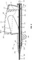
- FIG. 1 is a perspective view of a deployment device 100.
- the deployment device 100 comprises a handle assembly 102 adjacent the proximal end of the deployment device 100.
- An elongate delivery catheter assembly 104 extends distally from the handle assembly 102 to a delivery tip.
- the handle assembly 102 may provide a proximal user input, with one or more components configured to allow a practitioner to deploy or otherwise manipulate a stent disposed within the delivery catheter assembly 104.
- the handle assembly 102 may be disposed outside of a patient's body, while the delivery catheter assembly 104 is advanced to a treatment location within the patient's body.
- the delivery catheter assembly 104 may be advanced from an insertion site (such as, for example, a femoral or jugular insertion site) to a treatment location within the vasculature.
- the delivery catheter assembly 104 may be configured to be advanced through bends, turns, or other structures within the anatomy of the vasculature.
- a stent may be disposed within a portion of the delivery catheter assembly 104 such that a practitioner may deploy the stent from a distal end of the delivery catheter assembly 104 through manipulation of one or more components of the handle assembly 102.
- Figure 2 is a cross-sectional view of a portion of the deployment device 100 of Figure 1 .
- Figure 2 is a side view of a portion of the deployment device 100 of Figure 1 , taken through a cross-sectional plane extending vertically and intersecting a longitudinal axis of the deployment device 100, when the deployment device 100 is positioned as shown in Figure 1 .
- the longitudinal axis of the deployment device 100 extends along the center of the delivery catheter assembly 104, including along the center of components of the delivery catheter assembly 104 which overlap with the handle 102 assembly, such as the intermediate sheath 160, as shown in Figure 2 .
- the delivery catheter assembly 104 extends in a distal direction away from the handle assembly 102.
- the proximal direction is opposite, correlating to a direction defined along the longitudinal axis, extending from the delivery tip 174 toward the handle assembly 104.
- Figure 2 depicts various internal components of the handle assembly 102, exposed by the cross-sectional view. A portion of the delivery catheter assembly 104 is also shown extending from the handle assembly 102.
- the handle assembly 102 comprises a housing 110.
- the housing 110 surrounds certain components of the handle assembly 102, as shown, providing a grip surface for a practitioner.
- the housing 110 is operably coupled to an actuator 120. Manipulation of the actuator 120 with respect to the housing 110 may be configured to deploy the stent, as further detailed below.
- the actuator 120 is rotatably coupled to the housing 110 by a pin 112.
- the pin 112 extends from the housing 120 and may be integrally formed with one or more other portions of the housing 110. As shown, the pin 112 extends through a pin aperture 122 in the actuator 120.
- the pin 112 may be integral with a portion of the actuator 120 and may be received in an opening, sleeve, or aperture formed in the housing 110.
- Other types of designs of rotatable couplings, including a separate coupling component such as a hinge are within the scope of this disclosure.
- a compliant mechanism such as deformable flange, may be utilized to rotatably couple the actuator 120 and the housing 110, including compliant couplings integrally formed with the actuator 120, the housing 110, or both.
- the actuator 120 comprises an input portion 121 extending from the aperture 122.
- the input portion 121 comprises a surface, at least partially exposed with respect to the housing 110.
- a user may manipulate the actuator 120 by exerting a force on the input portion 121, illustrated by the arrow labeled "input” in Figure 2 , displacing the input portion 121 generally toward the longitudinal axis of the deployment device (100 of Figure 1 ) and causing the actuator 120 to rotate about the pin 112 with respect to the housing 110.
- Displacement of the actuator 120 due to a force such as illustrated by the arrow labeled "input” corresponds to "depression" of the actuator 120 or "depression of the actuator 120 with respect to the housing 110.”
- the actuator 120 may further comprise a transfer arm 123 extending from the pin aperture 122.
- the transfer arm 123 may be rigidly coupled to the input portion 121, including embodiments wherein both the transfer arm 123 and the input portion 121 are integrally formed with the rest of the actuator 120.
- the transfer arm 123 extends to a ratchet slide engaging portion 124. Depression of the input portion 121, in the direction shown by the arrow labeled "input" displaces the transfer arm 123 as the actuator 120 is rotated about the pin 112.
- Depression of the input portion 121 thus causes displacement of the ratchet slide engaging portion 124 with respect to the housing 110.
- This displacement of the ratchet slide engaging portion 124 can be understood as rotation about the pin 112 having a proximal translation component and a vertical translation component, as rotation of the input portion 121 in the direction indicated by the arrow labeled "input” will displace (with respect to the housing 110) the ratchet slide engaging portion 124 both proximally and vertically.
- a spring 115 may be disposed between the actuator 120 and the housing 110.
- the spring 115 may be configured to resist displacement of the actuator 120 in the direction indicated by the arrow labeled "input" and may be configured to return the actuator to the relative position shown in Figure 2 after it has been depressed by a user. When the handle assembly 102 is unconstrained, the spring 115 may thus maintain (or return to) the relative position of the actuator 120 with respect to the handle 110 as shown in Figure 2 .
- the spring 115 engages with a spring ledge 125 of the actuator 120 and spring protrusions 111 of the housing 110.
- the spring protrusions 111 may provide a bearing surface for the spring 115 offset from movable internal components of the handle assembly 102 (such as the carrier 140 further detailed below). Though three spring protrusions 111 are shown in the depicted embodiment, more or few protrusions, or use of other features such as ridges, ledges, shoulders, and so forth are within the scope of this disclosure.
- the depicted embodiment comprises a leaf spring 115.
- Other biasing elements such as coil springs, piston assemblies, compliant mechanisms, and so forth are likewise within the scope of this disclosure.
- a compliant portion of one or both of the housing 110 and actuator 120 may provide a biasing force analogous to that provided by the spring 115.
- Leaf springs, such as spring 115 may be configured to provide a relatively constant biasing force notwithstanding compression of the spring 115 as the actuator 120 is rotated depressed with respect to the housing 110.
- the spring 115 compresses and the ratchet slide engaging portion 124 is displaced as described above.
- the displacement of the ratchet slide engaging portion 124 with respect to the housing 110 can be understood as having a proximal component and a vertical component.
- the ratchet slide engaging portion 124 may be operably coupled to a ratchet slide 130 such that displacement of the ratchet slide engaging portion 124 likewise displaces the ratchet slide 130.
- the ratchet slide 130 may be constrained such that the ratchet slide 130 is configured only for proximal or distal displacement with respect to the housing 110.
- operable coupling of the ratchet slide engaging portion 124 to the ratchet slide 130 may allow for sliding interaction between the ratchet slide engaging portion 124 and the ratchet slide 130 such that only that proximal or distal component of the displacement of the ratchet slide engaging portion 124 is transferred to the ratchet slide 130.
- the ratchet slide 130 may be displaced in a direction parallel to the longitudinal axis of the deployment device 100 while the input displacement may be at an angle to the longitudinal axis of the deployment device 100.
- the safety member 180 may prevent proximal displacement of the ratchet slide 130.
- the safety member 180 including removal thereof, is discussed in more detail below. Discussion herein relating to displacement of the ratchet slide 130 and related components, may thus be understood as disclosure relevant to a configuration of the handle assembly 102 in which the safety member 180 has been removed.
- the ratchet slide 130 may thus be proximally displaced with respect to the housing 110.
- One or both of the ratchet slide 130 and actuator 120 may also interact with the housing 110 such that there is a positive stop to arrest the depression of the actuator 120 and/or proximal displacement of the ratchet slide 130.
- This positive stop may be an engaging ledge, shoulder, lug, detent, or other feature coupled to the housing 110, including features integrally formed on the housing 110.
- a full stroke of the actuator 120 may thus correspond to displacement from the unconstrained position shown in Figure 2 , to the positive stop caused by interaction with the housing 110 when the actuator 120 is depressed. Release of the actuator 120 following a full or a partial stroke may then result in return of the actuator 120 to the unconstrained state, due to the biasing force provided by the spring 115.
- the unconstrained state shown in Figure 2 refers to lack of constraint due to user input. In this state, the spring 115 may be partially compressed, and interaction between the actuator 120 and the housing 110 may prevent rotation of the actuator 120 about the pin 112 in the opposite direction to depression of the actuator 120, or the return direction. In other words, interaction between the actuator 120 and the housing 110 (or features of the housing 110) may create a positive stop to the return motion of the actuator 120 as well.
- the actuator 120 and the housing 110 may be coupled such that pinching of external materials (such as a practitioner's hand or a surgical drape) is minimized when the actuator 120 is depressed or returned.
- the actuator 120 may comprise a shell configured to mate with, and slide into, the housing 110. Though the components may slide and rotated with respect to each other, the interface of the components may be sufficiently close and/or smooth to minimize pinching or other engagement of external materials. This close and/or smooth interface may refer to interaction at the edges of the actuator 120 as it is displaced into the housing 110 and/or to interaction at the portion of the actuator 120 near the pin 112, as the actuator 120 returns to the unconstrained position.
- the input portion 121 of the actuator 120 may also comprise ridges or other features to facilitate handling or gripping of the actuator 120 during use.
- the ratchet slide 130 may thus be proximally displaced during depression of the actuator 120. Again, such displacement may correspond to a configuration in which the safety member 180 shown in Figure 2 has been removed. Proximal displacement of the ratchet slide 130 may also proximally displace the carrier 140 due to interaction between one or more carrier engaging ratchet lugs 136 on the ratchet slide 130 and a ratchet slide engaging arm 146 coupled to the carrier 140.
- Figure 3A is a perspective view of the ratchet slide 130 of the deployment device 100 of Figures 1 and 2 .
- Figure 3B is a cross-sectional view of the ratchet slide 130 of Figure 3A , taken through a vertical plane disposed along a longitudinal centerline of the ratchet slide 130. When the ratchet slide 130 is disposed within the handle assembly 102 of Figure 2 , this cross-sectional plane would intersect the longitudinal axis of the deployment device 100.
- the ratchet slide 130 may comprise a plurality of carrier engaging ratchet lugs 136.
- the carrier engaging ratchet lugs 136 may be spaced at even intervals along the longitudinal direction of the ratchet slide 130.
- exemplary carrier engaging ratchet lugs are denoted with reference numeral 136, while the distal most carrier engaging ratchet lug, disposed at the distal end of the ratchet slide 130 is denoted with reference numeral 136a.
- the ratchet slide 130 further comprises a ratchet slide safety opening 139 and an actuator engaging opening 134. These features are discussed in more detail below.
- interaction between the ratchet slide engaging portion 124 of the actuator 120 and the ratchet slide 130 may proximally displace the ratchet slide 130 with respect to the housing 110.
- Engagement between the carrier 140 and one of the carrier engaging ratchet lugs 136 may also proximally displace the carrier 140 as the ratchet slide 130 is proximally displaced with respect to the housing 110.
- the ratchet slide engaging arm 146 of the carrier 140 is engaged with the distal most carrier engaging ratchet lug 136a.
- Figure 4 is a side view of the carrier 140 of the deployment device 100 of Figures 1 and 2 .
- the ratchet slide engaging arm 146 extends radially away from a longitudinal axis of the carrier 140.
- the longitudinal axis of the carrier 140 is disposed along the longitudinal axis of the deployment device 100.
- Figure 5 is a cross-sectional view of a portion of the deployment device 100 shown in Figures 1 and 2 . Specifically, the actuator 120, ratchet slide 130, and carrier 140 are shown in Figure 5 , in the same relative positions, and along the same cross-sectional plane as in Figure 2 .
- the actuator 120 rotates around the pin aperture 122. This rotation causes displacement of the ratchet slide engaging portion 124 of the actuator 120.
- the component of this displacement correlating to proximal displacement of the ratchet slide engaging portion 124 also proximally translates the ratchet slide 130 due to interaction between the ratchet slide engaging portion 124 of the actuator 120 and the actuator engaging opening 134 of the ratchet slide 130.
- the walls or faces that define the actuatory engaging opening 134 may contact the ratchet slide engaging portion 124 such that the ratchet slide 130 is displaced when the actuator 120 is displced.
- Proximal displacement of the ratchet slide 130 also proximally displaces the carrier 140 due to interaction between the carrier engaging ratchet lugs 136 and the ratchet slide engaging arm 146.
- a distal surface of the ratchet slide engaging arm 146 is in contact with a proximal face of the distal most carrier engaging ratchet lug 136a. This contact exerts proximal force on the distal surface of the ratchet slide engaging arm 146, displacing the carrier 140 in a proximal direction. Accordingly, the ratchet slide 130 and carrier 140, will move proximally until the actuator 120 reaches the end of the stroke.
- Figure 6 is a cross-sectional view of the housing 110 and the carrier 140 in the same relative positions shown in Figure 2 .
- the cross-sectional plane of Figure 6 extends along the longitudinal axis of the deployment device, however, the cross-sectional plane of Figure 6 extends horizontally, orthogonal to the cross-sectional planes of Figures 2 , 3B , and 5 .
- the carrier 140 comprises a housing engaging arm 148 extending radially away from a longitudinal axis of the carrier 140.
- the housing 110 comprises a plurality of carrier engaging housing lugs 118.
- exemplary carrier engaging housing lugs are denoted by reference numeral 118, with the distal most carrier engaging housing lug denoted by reference numeral 118a.
- the housing engaging arm 148 (shown in Figure 6 ) of the carrier 140 will deflect radially inward due to contact with one of the carrier engaging housing lugs 118.
- the distal most carrier engaging ratchet lug 136a and the ratchet slide engaging arm 146 of the carrier 140 draws the carrier 140 proximally, the distal most carrier engaging housing lug 118a causes the housing engaging arm 148 to displace radially inward.
- the housing engaging arm 148 will continue to deflect radially inward until the distal end of the housing engaging arm 148 is positioned proximal of the distal most carrier engaging housing lug 118a, at which point the housing engaging arm 148 will return to the radially outward configuration shown in Figure 6 .
- the point at which the housing engaging arm 148 moves proximally of the distal most carrier engaging housing lug 118a may correspond to the stroke of the actuator 120, such that engagement between the housing engaging arm 148 and the next carrier engaging housing lug 118 (moving in a proximal direction) occurs at the end of the stroke, which may correspond to contact between the ratchet slide 130 and/or actuator 120 and a positive stop on the housing 110 defining the end of the stroke.
- distal displacement of the ratchet slide 130 with respect to the carrier 140 creates interaction between the carrier engaging ratchet lugs 136 and the ratchet slide engaging arm 146 causing the ratchet slide engaging arm 146 to displace radially inward.
- the proximal facing surface of the carrier engaging ratchet lugs 136 may be angled to facilitate this interaction.
- the ratchet slide engaging arm 136 returns to a radially outward position (analogous to that shown in Figure 5 ) though the distal surface of the ratchet slide engaging arm 136 is now engaged with a proximal face of the next carrier engaging ratchet lug 136 (again in a proximal direction). Displacement of the ratchet slide 130 sufficient to move to engagement with a subsequent carrier engaging ratchet lug 136 may correspond with the magnitude of ratchet slide 130 displacement corresponding to a return of the actuator 120. Subsequent returns of the actuator 120 following strokes move the ratchet slide 130 such that the plurality of carrier engaging ratchet lugs 136 may serially engage the carrier 140, stroke after stroke.
- depressing the actuator 120 for a full stroke then allowing the actuator 120 to return to the unconstrained position, displaces the carrier 140 with respect to the housing 110 in discrete increments, corresponding to the distance between adjacent carrier engaging housing lugs 118 along the longitudinal direction.
- Interaction of the actuator 120, positive stops associated with the housing 110, carrier arms 134, 136, and lugs 118, 136 may also combine to give a user tactile and audible feedback as the carrier 140 is incrementally displaced.
- one or more opening in the housing 110 may allow a user to observe the relative position of the carrier 140 providing further feedback as to carrier 140 position.
- the relative position of the carrier 140 with respect to the housing 110 may correlate to the degree of deployment of a stent from the deployment device 100.
- visual, audible, and tactile feedback as to the position of the carrier 140 provides a user with information regarding stent deployment during use of the deployment device 100. This information may correlated to increased control during deployment as the practitioner quickly and intuitively can surmise the degree of stent deployment.
- tactile and/or audible feedback back result from the interactions of the carrier 140, ratchet slide 130, housing 110, and/or actuator 120.
- the ratchet slide engaging arm 146 or housing engaging arm 148 of the carrier 140 deflect radially inward then return outward, there may be an auible and/or tactile response.
- the device may be configured for visual feedback of relating to the relative deployment of a stent.
- the housing 110 may comprise viewing windows to allow a practitioner to observe the position of the carrier 140 relative to the housing 110. Further, indicia on the housing 110 may correlate the position of the carrier 140 to the degree of deployment of a stent.
- the increments of displacement of the carrier 140 may correlate to standard stent lengths or units of measure. For example, many stents are sized in 1 cm increments. Configuration of the increments of displacement on the carrier 140 in 1 cm increments would thus directly correlate with stent length at a 1:1 ratio. Any other ratio, including embodiment wherein a stroke correlates to a greater length (such as 2, 3, 4, or 5 cm) or a lesser length (such as 0.25, 0.5, or 0.75 cm) are likewise within the scope of this disclosure.
- the deployment device 100 may be configured as a universal device operable with various stent lengths. In some embodiments a practitioner may directly equate the number of strokes needed to deploy a stent with the length of the stent loaded in the deployment device 100 (such as four strokes for a four centimeter stent). Further, a single design of deployment device 100 may be utilized with various lengths of stents, with a maximum length related to the maximum length of travel of the carrier 140.
- depression of the actuator 120 may facilitate one handed operation and may be ergonomically designed. First, a practitioner need only grip the deployment device with one hand to depress the actuator, leaving a second hand free for other therapy needs. Further, the direction with which the deployment device is gripped, with the practitioner's hand extending laterally away from the longitudinal axis of the deployment device and the lateral direction of depression, as opposed, for example to longitudinal gripping to actuate, may be ergonomically desirable. Lateral gripping and input may more readily present the deployment device 100 for use when the delivery catheter assembly 104 is disposed within a patient's body, not requiring the practitioner to move to an awkward stance with respect to other therapy tools. Further, the input portion 121 of the actuator 120 may provided additional surface for a practitioner to grip, facilitating use of a greater portion of a practitioner's hand for actuation, as compared to a finger trigger or similar actuation mechanism.
- the incremental displacement of the carrier 140 may further facilitate partial deployment of a stent, allowing a practitioner to deploy the stent in increments, potential adjusting or confirming the position of the stent between these increments.
- the deployment device 100 may be configured for use with either the right or left hand, or gripped with the fingers or palm in contact with the actuator 120 without changing the design of the deployment device 100. These features may further increase user comfort and control. Viewing windows in the housing 110 to confirm the position on the carrier 140 may be located on one or both sides of the housing 110 and may be associated with indicia correlating to stent length or other factors.
- the relative lengths of the input portion 121 and transfer arm 123 of the actuator 120 may be configured to provide mechanical advantage when deploying a stent. This may increase comfort and control during use.
- the ratio of the length of the input portion 121-from its distal end to the pin aperture 122-to the length of the transfer arm 123-from the pin aperture 122 to the ratchet slide engaging portion 124- may be greater than or equal to 1.5:1, including 2:1, 2.5:1, 3:1, 3.5:1 or greater. This ratio correlates to the mechanical advantage provided by the device. In some instances the mechanical advantage provided may be 1.5:1, 2:1, 2.5:1, 3:1, 3.5:1 or greater.
- the ratio of length of travel of the input portion 121 to the corresponding length of travel of the ratchet slide engaging portion 124 may be 1.5:1, 2:1, 2.5:1, 3:1, 3.5:1 or greater. Accordingly, the input force applied against the input portion 121 may result in a greater force exerted by the ratchet slide engaging portion 124 on the ratchet slide 130.
- the ratio of the force exerted on the ratchet slide 130 to the input force may be 1.5:1, 2:1, 2.5:1, 3:1, 3.5:1 or greater.
- Figure 7 is a front view of the deployment device 100, illustrating two cross-sectional planes. Specifically, plane A-A extends vertically along the longitundal axis of the deployment device 100 viewing the exposed components in a right to left direction. Plane A-A corresponds to the cross-sectional plane of Figures 2 , 3B , and 5 . Plane B-B also extends from the longitudinal axis of the deployment device 100, though Plane B-B extends horizontally therefrom. Plane B-B corresponds to the cross-sectional plane of Figure 6 , and is viewed from a top to bottom direction. The longitudinal axis of the deployment device 100 is in both planes A-A and B-B, with the line defined as the intersection between these planes being the same line as the longitudinal axis as referenced herein.
- the deployment device 100 may comprise a safety member 180.
- Figure 8 is a perspective view of the safety member 180 of the deployment device 100.
- the safety member 180 may be configured with a circular or partially circular opening configured to snap onto an outside surface of a portion of the deployment device 100.
- the safety member 180 may comprise a safety lug 189 that extends through a ratchet slide safety opening (139 of Figure 3A ) and a similar safety opening in the housing 110 (not shown). When the safety lug 189 is disposed within these openings, the safety lug 189 may prevent proximal displacement of the carrier 140 and the ratchet slide 130, thus preventing inadvertent deployment of a stent.
- a practitioner may leave the safety member 180 in place during displacement of the delivery catheter assembly 104 to a treatment region. Due to interactions between the carrier 140, ratchet slide 130, and actuator 120, the safety member 180 likewise prevents displacement of the actuator 120 when the safety lug 189 extends through the openings.
- the safety lug 189 extends through a bottom portion of the housing 110 and ratchet slide 130. In other embodiments, the safety lug 189 may extend through a top surface of the housing 110, interacting with the carrier 140 but not directly with the ratchet slide 130. Nevertheless, prevention of proximal displacement on the carrier 140 only, will also prevent displacement of the ratchet slide 130 and the actuator 120 due to the interaction between these elements.
- the safety member 180 may be tethered to the deployment device 100, or may comprise a sliding switch or other element operably coupled to the housing 110 or other components of the deployment device 100. In the depicted embodiment, the safety member 180 is removably coupled.
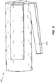
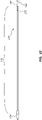
- Figure 9 is a side view of a portion of the delivery catheter assembly 104 of the deployment device 100. Specifically, Figure 9 is a side view of a distal section of the delivery catheter assembly 104. Figure 10 is a side view of the same longitudinal section of the delivery catheter assembly 104 as shown in Figure 9 , however, the outer sheath (150 of Figure 9 ) has been removed to show other components.
- the delivery catheter assembly 104 may be configured to deploy a stent as the deployment device 100 is manipulated, as discussed above.
- the delivery catheter assembly 104 may comprise an outer sheath 150, extending from the handle assembly 102.
- the outer sheath 150 may be fixedly coupled to the carrier 140.
- the delivery catheter assembly 104 may further comprise an intermediate sheath 160 and an inner sheath 170, both disposed within the outer sheath 150, and both fixedly coupled to the housing 110.
- proximal displacement of the carrier 140 with respect to the housing 110 will proximally displace the outer sheath 150 with respect to both the intermediate sheath 160 and the inner sheath 170.
- the outer sheath 150 may comprise a shaft section 156 extending from the carrier 140 in a distal direction. At the distal end of the shaft section 156 the outer sheath 150 may comprise a flex zone 154 extending from the shaft section 156 in a distal direction. Finally, the outer sheath 150 may comprise a pod 152 extending from the flex zone 154 in a distal direction. (As shown in Figure 9 , the pod 152 may be transparent.)
- the shaft section 156 of the outer sheath 150 may have a different stiffness and/or durometer than the flex zone 154 and/or the pod 152.
- the flexibility toward the distal end of the outer sheath 150 may improve trackability of the delivery catheter assembly 104 over a guidewire and may be less traumatic, while a stiffer shaft may be more kink resistant and/or transmit displacement and/or torque along the shaft section 156.
- the pod 152 may be configured to retain a crimped or otherwise constrained stent. Removal of the pod 152 from the stent may allow the stent to self-expand, and thereby deploy. It is within the scope of this disclosure for the pod 152 to be any relative length, the flex zone 154 to be any relative length, and the shaft section 156 to be any relative length. Thus, in some instances, a constrained stent may be in one, two, or all three of these portions of the outer sheath 150.
- an annular space 176 (described further below), configured to receive a crimped stent extend along the pod 152 as well as portions of the flex zone 154 and shaft section 156. In other embodiments, the annular space 176 may correlate just to the pod 152 segment, meaning the device is configured to retain a crimped stent only within the pod 152 segment.
- the distal tip 174 of the delivery sheath assembly 104 may be coupled to and/or integrally formed with the inner sheath 170.
- a lumen 172 may extend along the inner sheath 170 from the proximal end of the deployment device 100 to the distal tip 174.
- a luer fitting 113 coupled to the housing 110 may be in communication with the lumen 172.
- a guidewire may thus extend through the luer fitting 113 through the lumen 172 and out of the distal tip 174. Further, fluid introduced into the luer fitting 113 may be utilized to flush the lumen 172.
- the inner sheath 170 may be fixed to the housing, for example, at the proximal end of the inner sheath 170.
- An intermediate sheath 160 also fixed to the housing 110, may extend over a portion of the inner sheath 170.
- the intermediate sheath 160 and inner sheath 170 may or may not be directly fixed to each other.
- the intermediate sheath 160 may be a close slip fit over the inner sheath 170.
- the inner sheath 170 extends distally beyond a distal end of the intermediate sheath 160, creating an annular space 176 between the inner sheath 170 and the outer sheath 150 adjacent the distal tip 174, extending proximally to the distal end of the intermediate sheath 160.
- This annular space 176 may be configured to retain a crimped stent.
- the outer sheath 150 is incrementally displaced proximally with respect to the inner sheath 170 and intermediate sheath 160.
- the distal end of the intermediate sheath 160 interacts with the proximal end of the stent, preventing the stent from being drawn back with the outer sheath 150.
- the stent is incrementally exposed, and allowed to self-expand and deploy.
- a fluid aperture 162 in the intermediate sheath 160 may extend through the wall of the intermediate sheath 160 and the wall of the inner sheath 170, into fluid communication with the inner lumen 172.
- This fluid aperture 162 may thus provide fluid communication between the annular space 176 and the inner lumen 172, as fluid within the inner lumen 172 can move through the fluid aperture 162 and into the annular space 176.
- This communication may be used to flush the annular space 176, during use, which may be configured to remove air or other unwanted materials in the annular space 176 or around the crimped stent.
- the distal tip 174 may comprise a flexible material and may be configured to be atraumatic.
- the distal tip 174 may comprise nylons including PBAX.
- braided or coil reinforcements may be added to the outer sheath 150, the intermediate sheath 160, and/or the inner sheath 170 to increase kink resistance and/or elongation.
- Reinforcing members may comprise stainless steel, nitinol, or other materials and may be round, flat, rectangular in cross section, and so forth.
- One, two, or all of the outer sheath 150, the intermediate sheath 160, and/or the inner sheath 170 may be configured with varying durometers or other properties along the length thereof.
- the outer sheath 150 may be configured with a proximal section with a durometer between 72 and 100 on the Shore D scale or may be greater than 100 on the Shore D scale.
- a second portion of the outer sheath 150 may comprise a durometer of 63 on the Shore D scale, and a distal section with a durometer between 40 and 55 on the Shore D scale. Any of these values, or the limits of any of the ranges may vary by 15 units in either direction.
- the second portion will begin about 6 inches from the distal end of the outer sheath 150 and the distal section will begin about three inches from the distal end of the outer sheath 150.
- These sections may or may not correspond to the shaft section 156, the flex zone 154, and the pod 152 as described above.
- the intermediate sheath 160 may be configured with varying durometer zones within the same ranges of hardness and length.
- any of the inner sheath 170, intermediate sheath 160, and outer sheath 150 may have differing durometer or flex zones along their lengths, and these zones may overlap in various ways to create various stress/strain profiles for the overall delivery catheter assembly 104. Overlapping of such zones may reduce tendency to kink, including tendency to kink at transition zones. Further the housing 110 may be coupled to a strain relief member 116 (as shown in Figure 2 ).
- outer sheath 150, the intermediate sheath 160, and the inner sheath 170 may be comprised of nylons, including PBAX. Further, during manufacture, any of these members may be configured with a low friction outer surface, including through "frosting” the materials, or blowing air across the material during extrusion.
- the distal tip 174 may be pulled into interference with the outer sheath 150, prestressing the inner sheath 170 in tension. This may reduce any effects of material creep or elongation during sterilization, keeping the distal tip 174 snugly nested with the outer sheath 150.
- the interface zone between the outer sheath 150 and the carrier 140 may be configured with a tolerance zone, meaning the outer sheath 150 can be coupled to the carrier 140 at multiple points along an inside diameter of the carrier 140. This tolerance may enable manufacturing discrepancies or variations to be taken up during assembly to ensure a snug nest between the distal tip 174 and the outer sheath 150.
- the same tolerance fit may be applied to the inner sheath 170 and/or the intermediate sheath 160 wherein these members couple to the housing 110, including a fit zone along an inside diameter of the luer fitting 113.
- the outer sheath 150 may include indicia correlating to the degree to which a stent has been deployed. These indicia may correspond to the position of the outer sheath 150 with respect to the housing 110, as the outer sheath 150 is drawn into the housing 110, different indicia are exposed and/or covered, for example.
- the deployment device 100 may be configured such that the outer sheath 150 may be distally displaced after the stent is deployed to nest the distal tip 174 in the outer sheath 150 during withdrawal of the deployment device 100 from a patient.
- Such configurations may include features of the handle assembly 102 that disengage the carrier 140 from one or more elements after stent deployment.
Claims (9)
- Prothesenplatziervorrichtung (100), die Folgendes umfasst:eine langgestreckte Einführkatheteranordnung (104), die dazu konfiguriert ist, eine Prothese zu halten und zu platzieren;ein Gehäuse (110), das betriebsfähig an die Einführkatheteranordnung (104) gekoppelt ist; undeinen Aktor (120), der betriebsfähig derart an das Gehäuse (110) gekoppelt ist, dass eine Auslenkung des Aktors (120) einen Abschnitt der Einführkatheteranordnung (104) auslenkt, um die Prothese zu platzieren,dadurch gekennzeichnet, dass:die Auslenkung der Einführkatheteranordnung (104), um die Prothese zu platzieren in einer Richtung parallel zu einer Längsachse der Platziervorrichtung erfolgt und die Auslenkung des Aktors (120), um den Abschnitt der Einführkatheteranordnung (104) auszulenken, in einer unter einem Winkel zu der Längsachse der Platziervorrichtung angeordneten Richtung erfolgt,wobei die Auslenkung einer Ratschengleitschiene (130) einen Träger (140) entlang der Ratschengleitschiene (130) inkrementell voranbewegt, undwobei der Träger (140) einen Ratschengleitschienen-Eingriffsarm (146), der sich von dem Träger (140) erstreckt, um in die Ratschengleitschiene (130) einzugreifen, und einen Gehäuseeingriffsarm (148), der sich von dem Träger (140) erstreckt, um in das Gehäuse (110) einzugreifen, umfasst, wobei sich der Aktor (120) um einen Zapfen (112) dreht, wenn der Aktor (120) verschoben wird, um die Prothese zu platzieren, undwobei der Aktor (120) derart an die Ratschengleitschiene (130) gekoppelt ist, dass die Drehung des Aktors (120) um den Zapfen (112) die Ratschengleitschiene (130) parallel zu der Längsachse der Platziervorrichtung (100) auslenkt.
- Prothesenplatziervorrichtung (100) nach Anspruch 1, wobei die Einführkatheteranordnung (104) eine äußere Hülse (150) umfasst und die äußere Hülse (150) feststehend an den Träger (140) gekoppelt ist.
- Prothesenplatziervorrichtung (100) nach Anspruch 2, wobei die Einführkatheteranordnung (104) innere äußere Hülse (170) umfasst, die feststehend an das Gehäuse (110) gekoppelt ist.
- Prothesenplatziervorrichtung (100) nach einem der Ansprüche 1 bis 3, wobei die Platziervorrichtung eine mechanische Kraftverstärkung derart bereitstellt, dass eine auf den Abschnitt der Einführkatheteranordnung (104) übertragene Ausgangskraft zum Platzieren der Prothese größer ist als eine Eingangskraft zum Auslenken des Aktors (120).
- Prothesenplatziervorrichtung (100) nach Anspruch 4, wobei das Verhältnis der Ausgangskraft zu der Eingangskraft größer als 1,5 : 1 ist.
- Prothesenplatziervorrichtung (100) nach einem der Ansprüche 1 bis 5, wobei der Aktor (120) die Prothese inkrementell platziert.
- Prothesenplatziervorrichtung (100) nach Anspruch 6, wobei der Aktor (120) dazu konfiguriert ist, entlang eines Hubs auslenkbar zu sein und wobei ein Hub des Aktors (120) nur einen Abschnitt der Prothese platziert.
- Prothesenplatziervorrichtung (100) nach Anspruch 7, wobei die Platziervorrichtung (100) eine hörbare Rückmeldung am Ende eines Hubs bereitstellt.
- Prothesenplatziervorrichtung (100) nach einem der Ansprüche 7 bis 8, wobei die Platziervorrichtung (100) eine tastbare Rückmeldung am Ende eines Hubs bereitstellt.
Applications Claiming Priority (2)
| Application Number | Priority Date | Filing Date | Title |
|---|---|---|---|
| US201562129006P | 2015-03-05 | 2015-03-05 | |
| PCT/US2016/020900 WO2016141295A1 (en) | 2015-03-05 | 2016-03-04 | Vascular prosthesis deployment device and method of use |
Publications (3)
| Publication Number | Publication Date |
|---|---|
| EP3265025A1 EP3265025A1 (de) | 2018-01-10 |
| EP3265025A4 EP3265025A4 (de) | 2018-10-24 |
| EP3265025B1 true EP3265025B1 (de) | 2022-04-13 |
Family
ID=56848698
Family Applications (1)
| Application Number | Title | Priority Date | Filing Date |
|---|---|---|---|
| EP16759580.0A Active EP3265025B1 (de) | 2015-03-05 | 2016-03-04 | Vorrichtung zur freisetzung einer gefässprothese |
Country Status (6)
| Country | Link |
|---|---|
| US (1) | US10285834B2 (de) |
| EP (1) | EP3265025B1 (de) |
| JP (1) | JP2018507056A (de) |
| KR (1) | KR102541896B1 (de) |
| CA (1) | CA2977681A1 (de) |
| WO (1) | WO2016141295A1 (de) |
Families Citing this family (7)
| Publication number | Priority date | Publication date | Assignee | Title |
|---|---|---|---|---|
| EP3215072B1 (de) * | 2014-11-04 | 2021-03-10 | Abbott Cardiovascular Systems Inc. | System zur freisetzung eines implantats |
| US10799378B2 (en) * | 2016-09-29 | 2020-10-13 | Merit Medical Systems, Inc. | Pliant members for receiving and aiding in the deployment of vascular prostheses |
| US10940030B2 (en) * | 2017-03-10 | 2021-03-09 | Serenity Medical, Inc. | Method and system for delivering a self-expanding stent to the venous sinuses |
| US10744009B2 (en) | 2017-03-15 | 2020-08-18 | Merit Medical Systems, Inc. | Transluminal stents and related methods |
| US11628078B2 (en) | 2017-03-15 | 2023-04-18 | Merit Medical Systems, Inc. | Transluminal delivery devices and related kits and methods |
| US11013627B2 (en) * | 2018-01-10 | 2021-05-25 | Boston Scientific Scimed, Inc. | Stent delivery system with displaceable deployment mechanism |
| WO2023156879A1 (en) * | 2022-02-15 | 2023-08-24 | Medtronic, Inc. | Cardiac prosthesis delivery device having device position feedback |
Family Cites Families (151)
| Publication number | Priority date | Publication date | Assignee | Title |
|---|---|---|---|---|
| SE8803444D0 (sv) | 1988-09-28 | 1988-09-28 | Medinvent Sa | A device for transluminal implantation or extraction |
| US5591172A (en) | 1991-06-14 | 1997-01-07 | Ams Medinvent S.A. | Transluminal implantation device |
| FR2688401B1 (fr) | 1992-03-12 | 1998-02-27 | Thierry Richard | Endoprothese expansible pour organe tubulaire humain ou animal, et outil de mise en place. |
| US5201757A (en) | 1992-04-03 | 1993-04-13 | Schneider (Usa) Inc. | Medial region deployment of radially self-expanding stents |
| ATE247435T1 (de) | 1992-05-08 | 2003-09-15 | Schneider Usa Inc | Stent für den oesophagus |
| DE9209908U1 (de) | 1992-07-23 | 1992-09-17 | Neuss, Malte, Dipl.-Ing. (Fh), 5300 Bonn, De | |
| ES2135520T3 (es) | 1993-11-04 | 1999-11-01 | Bard Inc C R | Protesis vascular no migrante. |
| US5591196A (en) | 1994-02-10 | 1997-01-07 | Endovascular Systems, Inc. | Method for deployment of radially expandable stents |
| US5824041A (en) | 1994-06-08 | 1998-10-20 | Medtronic, Inc. | Apparatus and methods for placement and repositioning of intraluminal prostheses |
| ES2340142T3 (es) | 1994-07-08 | 2010-05-31 | Ev3 Inc. | Sistema para llevar a cabo un procedimiento intravascular. |
| US6123715A (en) | 1994-07-08 | 2000-09-26 | Amplatz; Curtis | Method of forming medical devices; intravascular occlusion devices |
| US6579314B1 (en) | 1995-03-10 | 2003-06-17 | C.R. Bard, Inc. | Covered stent with encapsulated ends |
| US5571168A (en) | 1995-04-05 | 1996-11-05 | Scimed Lifesystems Inc | Pull back stent delivery system |
| DE69526857T2 (de) | 1995-11-27 | 2003-01-02 | Schneider Europ Gmbh Buelach | Stent zur Anwendung in einem körperlichen Durchgang |
| CN1218414A (zh) | 1996-02-02 | 1999-06-02 | 血管转换公司 | 连接在相邻血管或其它解剖学结构上形成的开口的方法与装置 |
| US6273912B1 (en) | 1996-02-28 | 2001-08-14 | Impra, Inc. | Flanged graft for end-to-side anastomosis |
| US6702846B2 (en) | 1996-04-09 | 2004-03-09 | Endocare, Inc. | Urological stent therapy system and method |
| US6413269B1 (en) | 2000-07-06 | 2002-07-02 | Endocare, Inc. | Stent delivery system |
| US5830179A (en) | 1996-04-09 | 1998-11-03 | Endocare, Inc. | Urological stent therapy system and method |
| US6629981B2 (en) | 2000-07-06 | 2003-10-07 | Endocare, Inc. | Stent delivery system |
| US6254628B1 (en) | 1996-12-09 | 2001-07-03 | Micro Therapeutics, Inc. | Intracranial stent |
| US5968052A (en) * | 1996-11-27 | 1999-10-19 | Scimed Life Systems Inc. | Pull back stent delivery system with pistol grip retraction handle |
| US5868755A (en) | 1997-01-16 | 1999-02-09 | Atrion Medical Products, Inc. | Sheath retractor mechanism and method |
| US6241757B1 (en) | 1997-02-04 | 2001-06-05 | Solco Surgical Instrument Co., Ltd. | Stent for expanding body's lumen |
| US6143016A (en) | 1997-04-21 | 2000-11-07 | Advanced Cardiovascular Systems, Inc. | Sheath and method of use for a stent delivery system |
| US5916147A (en) | 1997-09-22 | 1999-06-29 | Boury; Harb N. | Selectively manipulable catheter |
| US20100030256A1 (en) | 1997-11-12 | 2010-02-04 | Genesis Technologies Llc | Medical Devices and Methods |
| DE69836764T2 (de) | 1997-11-14 | 2007-10-04 | Boston Scientific Ltd., St. Michael | Katheter mit mehrfachhülle zur einführung einer prothese |
| US6776791B1 (en) | 1998-04-01 | 2004-08-17 | Endovascular Technologies, Inc. | Stent and method and device for packing of same |
| US6143021A (en) | 1998-07-10 | 2000-11-07 | American Medical Systems, Inc. | Stent placement instrument and method of assembly |
| US5944727A (en) * | 1998-09-02 | 1999-08-31 | Datascope Investment Corp. | Stent/graft catheter handle |
| US6093194A (en) | 1998-09-14 | 2000-07-25 | Endocare, Inc. | Insertion device for stents and methods for use |
| US6162231A (en) | 1998-09-14 | 2000-12-19 | Endocare, Inc. | Stent insertion device |
| US6547814B2 (en) | 1998-09-30 | 2003-04-15 | Impra, Inc. | Selective adherence of stent-graft coverings |
| MXPA01003283A (es) * | 1998-09-30 | 2002-07-02 | Impra Inc | Mecanismo de suministro para un dispositivo de stent implantable. |
| CA2593763C (en) | 1998-12-31 | 2008-11-18 | Kensey Nash Corporation | Tissue fastening devices and delivery means |
| US7018401B1 (en) | 1999-02-01 | 2006-03-28 | Board Of Regents, The University Of Texas System | Woven intravascular devices and methods for making the same and apparatus for delivery of the same |
| US6309350B1 (en) | 1999-05-03 | 2001-10-30 | Tricardia, L.L.C. | Pressure/temperature/monitor device for heart implantation |
| US6146415A (en) | 1999-05-07 | 2000-11-14 | Advanced Cardiovascular Systems, Inc. | Stent delivery system |
| US6726712B1 (en) | 1999-05-14 | 2004-04-27 | Boston Scientific Scimed | Prosthesis deployment device with translucent distal end |
| SE515405C2 (sv) | 2000-01-25 | 2001-07-30 | Gudmar Olovson | Nålskyddsarrangemang |
| DK1263349T3 (da) | 2000-03-14 | 2009-10-19 | Cook Inc | Endovaskulær stentgraft |
| US20030135268A1 (en) | 2000-04-11 | 2003-07-17 | Ashvin Desai | Secure stent for maintaining a lumenal opening |
| US6821295B1 (en) | 2000-06-26 | 2004-11-23 | Thoratec Corporation | Flared coronary artery bypass grafts |
| US20020193863A1 (en) | 2000-09-18 | 2002-12-19 | Endotex Interventional Systems, Inc. | Apparatus for delivering endoluminal prosthesis and methods for preparing such apparatus for delivery |
| US6428566B1 (en) | 2000-10-31 | 2002-08-06 | Advanced Cardiovascular Systems, Inc. | Flexible hoop and link sheath for a stent delivery system |
| GB0110551D0 (en) * | 2001-04-30 | 2001-06-20 | Angiomed Ag | Self-expanding stent delivery service |
| US6926732B2 (en) | 2001-06-01 | 2005-08-09 | Ams Research Corporation | Stent delivery device and method |
| US6599296B1 (en) * | 2001-07-27 | 2003-07-29 | Advanced Cardiovascular Systems, Inc. | Ratcheting handle for intraluminal catheter systems |
| US6755854B2 (en) * | 2001-07-31 | 2004-06-29 | Advanced Cardiovascular Systems, Inc. | Control device and mechanism for deploying a self-expanding medical device |
| US6770101B2 (en) | 2001-10-09 | 2004-08-03 | Scimed Life Systems, Inc. | Prostatic stent and delivery system |
| US6866669B2 (en) | 2001-10-12 | 2005-03-15 | Cordis Corporation | Locking handle deployment mechanism for medical device and method |
| US6939352B2 (en) | 2001-10-12 | 2005-09-06 | Cordis Corporation | Handle deployment mechanism for medical device and method |
| US7309350B2 (en) | 2001-12-03 | 2007-12-18 | Xtent, Inc. | Apparatus and methods for deployment of vascular prostheses |
| US20030135265A1 (en) | 2002-01-04 | 2003-07-17 | Stinson Jonathan S. | Prostheses implantable in enteral vessels |
| US6893413B2 (en) | 2002-01-07 | 2005-05-17 | Eric C. Martin | Two-piece stent combination for percutaneous arterialization of the coronary sinus and retrograde perfusion of the myocardium |
| US7578843B2 (en) | 2002-07-16 | 2009-08-25 | Medtronic, Inc. | Heart valve prosthesis |
| US7001422B2 (en) | 2002-09-23 | 2006-02-21 | Cordis Neurovascular, Inc | Expandable stent and delivery system |
| JP4995420B2 (ja) | 2002-09-26 | 2012-08-08 | アドヴァンスド バイオ プロスセティック サーフェシーズ リミテッド | 高強度の真空堆積されたニチノール合金フィルム、医療用薄膜グラフト材料、およびそれを作製する方法。 |
| JP4648704B2 (ja) | 2002-09-30 | 2011-03-09 | ボード・オブ・リージエンツ,ザ・ユニバーシテイ・オブ・テキサス・システム | ステントデリバリーシステムとその使用方法。 |
| US7637942B2 (en) | 2002-11-05 | 2009-12-29 | Merit Medical Systems, Inc. | Coated stent with geometry determinated functionality and method of making the same |
| US7959671B2 (en) | 2002-11-05 | 2011-06-14 | Merit Medical Systems, Inc. | Differential covering and coating methods |
| US7637934B2 (en) | 2003-03-31 | 2009-12-29 | Merit Medical Systems, Inc. | Medical appliance optical delivery and deployment apparatus and method |
| US20040267281A1 (en) | 2003-06-25 | 2004-12-30 | Eran Harari | Delivery system for self-expandable diverter |
| US20060155368A1 (en) | 2003-07-29 | 2006-07-13 | Kyoung-Min Shin | Self-expandable stent |
| US7758625B2 (en) | 2003-09-12 | 2010-07-20 | Abbott Vascular Solutions Inc. | Delivery system for medical devices |
| US7635382B2 (en) | 2003-10-22 | 2009-12-22 | Medtronic Vascular, Inc. | Delivery system for long self-expanding stents |
| US20050125050A1 (en) | 2003-12-04 | 2005-06-09 | Wilson Cook Medical Incorporated | Biliary stent introducer system |
| US7887574B2 (en) | 2003-12-23 | 2011-02-15 | Scimed Life Systems, Inc. | Stent delivery catheter |
| US20070156225A1 (en) * | 2003-12-23 | 2007-07-05 | Xtent, Inc. | Automated control mechanisms and methods for custom length stent apparatus |
| JP5016310B2 (ja) | 2004-01-08 | 2012-09-05 | メリット・メディカル・システムズ・インコーポレイテッド | 移植可能装置送達システムのハンドルと使用方法 |
| US8425539B2 (en) | 2004-04-12 | 2013-04-23 | Xlumena, Inc. | Luminal structure anchoring devices and methods |
| US20050278010A1 (en) | 2004-05-27 | 2005-12-15 | Scimed Life Systems, Inc. | Stent delivery system with imaging capability |
| JP4901087B2 (ja) | 2004-09-24 | 2012-03-21 | オリンパス株式会社 | ステント導入部材、ステントデリバリーカテーテル、及び内視鏡処置システム |
| US7632313B2 (en) | 2005-04-29 | 2009-12-15 | Jmea Corporation | Disc repair system |
| EP1885287A2 (de) | 2005-05-13 | 2008-02-13 | Alveolus Inc. | Vorrichtung zur freisetzung eines endovaskulären implantats mit verankerungen und entsprechendes verfahren |
| US8986360B2 (en) | 2005-05-13 | 2015-03-24 | Merit Medical Systems, Inc. | Delivery device with shortened inner tube and associated method |
| US7731654B2 (en) | 2005-05-13 | 2010-06-08 | Merit Medical Systems, Inc. | Delivery device with viewing window and associated method |
| DE102005051469B4 (de) * | 2005-10-21 | 2011-07-28 | JOTEC GmbH, 72379 | Vorrichtung zum Einführen eines selbstexpandierenden Stents in ein Körpergefäß |
| US20070179590A1 (en) | 2005-12-29 | 2007-08-02 | Wenfeng Lu | Hybrid intraluminal device with varying expansion force |
| US20070208350A1 (en) | 2006-03-06 | 2007-09-06 | Gunderson Richard C | Implantable medical endoprosthesis delivery systems |
| EA013420B1 (ru) | 2006-03-20 | 2010-04-30 | Медикал Дивайс Воркс Нв Са | Прибор для медицинского лечения |
| US7591848B2 (en) | 2006-04-06 | 2009-09-22 | Medtronic Vascular, Inc. | Riveted stent valve for percutaneous use |
| US8221390B2 (en) | 2006-04-20 | 2012-07-17 | Cook Medical Technologies Llc | Medical device delivery system having a sheath with a flared strain relief member operatively coupled by a unidirectional handle |
| US7594928B2 (en) | 2006-05-17 | 2009-09-29 | Boston Scientific Scimed, Inc. | Bioabsorbable stents with reinforced filaments |
| US8535368B2 (en) | 2006-05-19 | 2013-09-17 | Boston Scientific Scimed, Inc. | Apparatus for loading and delivering a stent |
| BRPI0602379A (pt) | 2006-06-06 | 2008-01-22 | Luiz Gonzaga Granja Jr | prótese para anastomose |
| EP2591751B1 (de) | 2006-06-06 | 2018-11-28 | Cook Medical Technologies LLC | Stent mit stossfestem Bereich |
| US20080082159A1 (en) | 2006-09-28 | 2008-04-03 | Cook Incorporated | Stent for Endovascular Procedures |
| US8052732B2 (en) | 2006-11-14 | 2011-11-08 | Medtronic Vascular, Inc. | Delivery system for stent-graft with anchoring pins |
| US20080228256A1 (en) | 2007-03-13 | 2008-09-18 | Medtronic Vascular, Inc. | Braided Flange Branch Graft for Branch Vessel |
| EP3150171A1 (de) | 2007-05-15 | 2017-04-05 | JenaValve Technology, Inc. | Handgriff zur manipulation einer katheterspitze, kathetersystem und medizinisches einführungssystem zur einführung eines selbstexpandierenden herzklappenstents |
| US7766953B2 (en) | 2007-05-16 | 2010-08-03 | Med Institute, Inc. | Deployment system for an expandable stent |
| US8906081B2 (en) | 2007-09-13 | 2014-12-09 | W. L. Gore & Associates, Inc. | Stented vascular graft |
| US8518099B2 (en) | 2007-10-10 | 2013-08-27 | C. R. Bard, Inc. | Low friction vascular implant delivery device |
| US8043301B2 (en) | 2007-10-12 | 2011-10-25 | Spiration, Inc. | Valve loader method, system, and apparatus |
| US9414842B2 (en) | 2007-10-12 | 2016-08-16 | St. Jude Medical, Cardiology Division, Inc. | Multi-component vascular device |
| US20090143759A1 (en) | 2007-11-30 | 2009-06-04 | Jacques Van Dam | Methods, Devices, Kits and Systems for Defunctionalizing the Cystic Duct |
| CZ303081B6 (cs) | 2007-12-13 | 2012-03-21 | Ella-Cs, S. R. O. | Zpusob výroby samoexpanzního biodegradabilního stentu |
| US8075607B2 (en) * | 2007-12-27 | 2011-12-13 | Cook Medical Technologies Llc | Control handle |
| CA3010828A1 (en) | 2008-01-17 | 2009-07-23 | Boston Scientific Scimed, Inc. | Stent with anti-migration feature |
| CA2711755A1 (en) | 2008-01-24 | 2009-07-30 | Boston Scientific Scimed, Inc. | Apparatus and method for loading and delivering a stent having improved handles to control relative catheter component movement |
| US20090281379A1 (en) | 2008-05-12 | 2009-11-12 | Xlumena, Inc. | System and method for transluminal access |
| US8454632B2 (en) | 2008-05-12 | 2013-06-04 | Xlumena, Inc. | Tissue anchor for securing tissue layers |
| US9820746B2 (en) | 2008-07-28 | 2017-11-21 | Incube Laboratories LLC | System and method for scaffolding anastomoses |
| DK2313032T3 (da) | 2008-08-19 | 2021-02-15 | Merit Medical Systems Inc | Tilførselsanordning med et beskytttende element |
| US8359721B2 (en) | 2008-09-04 | 2013-01-29 | Cook Medical Technologies Llc | Sliding split-sleeve implant compressor |
| US8151682B2 (en) | 2009-01-26 | 2012-04-10 | Boston Scientific Scimed, Inc. | Atraumatic stent and method and apparatus for making the same |
| US9066785B2 (en) | 2009-04-06 | 2015-06-30 | Medtronic Vascular, Inc. | Packaging systems for percutaneously deliverable bioprosthetic valves |
| WO2010128501A1 (en) | 2009-05-04 | 2010-11-11 | V-Wave Ltd. | Device and method for regulating pressure in a heart chamber |
| WO2010130297A1 (en) | 2009-05-15 | 2010-11-18 | Jenavalve Technology Inc. | Device for compressing a stent and a system as well as a method for loading a stent into a medical delivery system |
| WO2010138277A1 (en) | 2009-05-29 | 2010-12-02 | Xlumena, Inc. | Apparatus and method for deploying stent across adjacent tissue layers |
| US8241345B2 (en) | 2009-07-30 | 2012-08-14 | Stryker Corporation | Stent delivery system |
| US8372133B2 (en) | 2009-10-05 | 2013-02-12 | 480 Biomedical, Inc. | Polymeric implant delivery system |
| WO2011060173A1 (en) | 2009-11-11 | 2011-05-19 | Alphatec Spine, Inc. | Instrument for insertion and deployment of features of an implant |
| US9414914B2 (en) | 2010-02-24 | 2016-08-16 | Medtronic Ventor Technologies Ltd. | Catheter assembly with valve crimping accessories |
| US20120046731A1 (en) | 2010-04-14 | 2012-02-23 | Abbott Vascular | Intraluminal scaffold with conforming axial strut |
| WO2011133792A1 (en) | 2010-04-23 | 2011-10-27 | Medtronic Inc. | Delivery systems and methods of implantation for prosthetic heart valves |
| WO2011137318A2 (en) | 2010-04-30 | 2011-11-03 | Boston Scientific Scimed, Inc. | Stent for repair of anastomasis surgery leaks |
| WO2011137043A1 (en) | 2010-04-30 | 2011-11-03 | Boston Scientific Scimed, Inc. | Apparatus and method for manufacturing a single wire stent |
| US8790386B2 (en) | 2010-05-14 | 2014-07-29 | Medtronic Vascular, Inc. | Catheter handle and methods of operating |
| US8814833B2 (en) | 2010-05-19 | 2014-08-26 | Tangent Medical Technologies Llc | Safety needle system operable with a medical device |
| WO2012003150A1 (en) | 2010-06-28 | 2012-01-05 | Cook Medical Technologies Llc | Covered stent |
| JP5926265B2 (ja) | 2010-09-24 | 2016-05-25 | シメティス・ソシエテ・アノニムSymetis Sa | ステント弁、送達装置、および送達方法 |
| WO2012062603A1 (de) | 2010-11-08 | 2012-05-18 | Völker AG | Höhenverstellbares untergestell für ein bett |
| CA2818687C (en) | 2010-12-07 | 2020-04-28 | Merit Medical Systems, Inc. | Stent delivery systems and methods |
| US9839540B2 (en) | 2011-01-14 | 2017-12-12 | W. L. Gore & Associates, Inc. | Stent |
| US20130018215A1 (en) | 2011-01-18 | 2013-01-17 | Merit Medical Systems, Inc. | Esophageal stent and methods for use of same |
| AU2011202174B1 (en) * | 2011-05-11 | 2011-08-25 | Cook Medical Technologies Llc | Introducer with ratchet handle drive |
| US8715334B2 (en) | 2011-07-14 | 2014-05-06 | Boston Scientific Scimed, Inc. | Anti-migration stent with quill filaments |
| US9387099B2 (en) | 2011-08-04 | 2016-07-12 | Cook Medical Technologies Llc | Non-woven helical wire stent |
| US20140364942A1 (en) | 2011-09-30 | 2014-12-11 | Jenavalve Technology Gmbh | System and method for loading a stent into a medical delivery system |
| US9320623B2 (en) | 2011-10-04 | 2016-04-26 | Cook Medical Technologies Llc | Reduced wire profile stent |
| US20130110221A1 (en) | 2011-10-27 | 2013-05-02 | Triona Campbell | Stent with Inwardly-Directed Protrusion |
| US9192496B2 (en) | 2011-10-31 | 2015-11-24 | Merit Medical Systems, Inc. | Systems and methods for sheathing an implantable device |
| US20130158673A1 (en) | 2011-12-15 | 2013-06-20 | Cook Medical Technologies Llc | Anti-Leakage Prosthesis |
| CN104114128A (zh) | 2011-12-19 | 2014-10-22 | 维斯拉生物医药有限公司 | 内腔假体和胃肠植入装置 |
| FR2984724B1 (fr) | 2011-12-23 | 2014-01-24 | Assist Publ Hopitaux De Paris | Prothese expansive destinee a etre implantee dans le tube digestif d'un patient. |
| US20150112377A1 (en) | 2012-05-08 | 2015-04-23 | The Curators Of The University Of Missouri | Embolic protection system |
| EP2854654B1 (de) | 2012-05-17 | 2019-11-06 | Boston Scientific Scimed, Inc. | Zugangsvorrichtungen zwischen aneinanderliegenden gewebeschichten |
| US20140074065A1 (en) | 2012-09-07 | 2014-03-13 | Acclarent, Inc. | Bioabsorbable Spacers and Spacer Delivery Systems for Use in the Ear, Nose and Throat |
| CA2870170C (en) | 2012-09-12 | 2018-06-12 | Boston Scientific Scimed, Inc. | Adhesive stent coating for anti-migration |
| CN102988122B (zh) | 2012-11-13 | 2013-11-06 | 浦易(上海)生物技术有限公司 | 一种用于治疗鼻窦炎或过敏性鼻炎的假体系统 |
| JP6342431B2 (ja) | 2013-02-21 | 2018-06-13 | ボストン サイエンティフィック サイムド,インコーポレイテッドBoston Scientific Scimed,Inc. | 吻合を形成するためのステントおよび同ステントを含む医療用具 |
| US9539126B2 (en) | 2013-02-28 | 2017-01-10 | Boston Scientific Scimed, Inc. | Medical devices for use along the biliary and/or pancreatic tract |
| US10087526B2 (en) | 2013-12-20 | 2018-10-02 | Microvention, Inc. | Stents, packaging, and substances used with stents |
| US11712230B2 (en) | 2014-05-02 | 2023-08-01 | W. L. Gore & Associates, Inc. | Occluder and anastomosis devices |
| US9993251B2 (en) | 2014-05-02 | 2018-06-12 | W. L. Gore & Associates, Inc. | Anastomosis devices |
| EP3193780A1 (de) | 2014-09-18 | 2017-07-26 | Boston Scientific Scimed Inc. | Vorrichtung zur ermöglichung der normalen funktion des magenpförtnermuskels für bariatrische stents |
| US20160081823A1 (en) | 2014-09-23 | 2016-03-24 | Cordis Corporation | Endoprosthesis with predetermined curvature formed by tri-tethers |
| EP3215072B1 (de) * | 2014-11-04 | 2021-03-10 | Abbott Cardiovascular Systems Inc. | System zur freisetzung eines implantats |
-
2016
- 2016-03-04 JP JP2017545633A patent/JP2018507056A/ja active Pending
- 2016-03-04 CA CA2977681A patent/CA2977681A1/en active Pending
- 2016-03-04 EP EP16759580.0A patent/EP3265025B1/de active Active
- 2016-03-04 KR KR1020177026786A patent/KR102541896B1/ko active IP Right Grant
- 2016-03-04 WO PCT/US2016/020900 patent/WO2016141295A1/en active Application Filing
- 2016-03-04 US US15/061,107 patent/US10285834B2/en active Active
Also Published As
| Publication number | Publication date |
|---|---|
| WO2016141295A1 (en) | 2016-09-09 |
| CA2977681A1 (en) | 2016-09-09 |
| US10285834B2 (en) | 2019-05-14 |
| KR20170125862A (ko) | 2017-11-15 |
| EP3265025A1 (de) | 2018-01-10 |
| JP2018507056A (ja) | 2018-03-15 |
| EP3265025A4 (de) | 2018-10-24 |
| KR102541896B1 (ko) | 2023-06-08 |
| US20160256306A1 (en) | 2016-09-08 |
Similar Documents
| Publication | Publication Date | Title |
|---|---|---|
| EP3265025B1 (de) | Vorrichtung zur freisetzung einer gefässprothese | |
| US10799378B2 (en) | Pliant members for receiving and aiding in the deployment of vascular prostheses | |
| US20220151778A1 (en) | Gripping and pushing device for medical instrument | |
| EP2480278B1 (de) | Schliessmechanismus für eine medizinische vorrichtung | |
| EP1701675B1 (de) | Griff für ein implantatablagesystem und anwendungsverfahren | |
| EP3120813B1 (de) | Vorrichtung zur katheterhüllenretraktion | |
| WO2010021836A1 (en) | Delivery device with a protective member | |
| WO2014159116A1 (en) | Valve loader method, system, and apparatus | |
| CN107427379A (zh) | 自扩张型支架输送系统 | |
| US20220273477A1 (en) | Devices and methods for deployment of a vascular prosthesis | |
| US20240000594A1 (en) | Integrated deployment balloon stent delivery | |
| EP2872076B1 (de) | Stenteinführvorrichtung | |
| US20240000591A1 (en) | Resilience adaptive stent delivery device and methods | |
| US20140239658A1 (en) | Release device for releasing a medical implant from an insertion device, and insertion device comprising a release device | |
| CN115151219A (zh) | 用于输送系统的可偏转轴 |
Legal Events
| Date | Code | Title | Description |
|---|---|---|---|
| STAA | Information on the status of an ep patent application or granted ep patent |
Free format text: STATUS: THE INTERNATIONAL PUBLICATION HAS BEEN MADE |
|
| PUAI | Public reference made under article 153(3) epc to a published international application that has entered the european phase |
Free format text: ORIGINAL CODE: 0009012 |
|
| STAA | Information on the status of an ep patent application or granted ep patent |
Free format text: STATUS: REQUEST FOR EXAMINATION WAS MADE |
|
| 17P | Request for examination filed |
Effective date: 20170906 |
|
| AK | Designated contracting states |
Kind code of ref document: A1 Designated state(s): AL AT BE BG CH CY CZ DE DK EE ES FI FR GB GR HR HU IE IS IT LI LT LU LV MC MK MT NL NO PL PT RO RS SE SI SK SM TR |
|
| AX | Request for extension of the european patent |
Extension state: BA ME |
|
| DAV | Request for validation of the european patent (deleted) | ||
| DAX | Request for extension of the european patent (deleted) | ||
| A4 | Supplementary search report drawn up and despatched |
Effective date: 20180924 |
|
| RIC1 | Information provided on ipc code assigned before grant |
Ipc: A61F 2/95 20130101AFI20180918BHEP Ipc: A61F 2/966 20130101ALN20180918BHEP |
|
| STAA | Information on the status of an ep patent application or granted ep patent |
Free format text: STATUS: EXAMINATION IS IN PROGRESS |
|
| 17Q | First examination report despatched |
Effective date: 20210504 |
|
| REG | Reference to a national code |
Ref country code: DE Ref legal event code: R079 Ref document number: 602016071055 Country of ref document: DE Free format text: PREVIOUS MAIN CLASS: A61F0002060000 Ipc: A61F0002950000 |
|
| RIC1 | Information provided on ipc code assigned before grant |
Ipc: A61F 2/966 20130101ALN20210819BHEP Ipc: A61F 2/95 20130101AFI20210819BHEP |
|
| GRAP | Despatch of communication of intention to grant a patent |
Free format text: ORIGINAL CODE: EPIDOSNIGR1 |
|
| STAA | Information on the status of an ep patent application or granted ep patent |
Free format text: STATUS: GRANT OF PATENT IS INTENDED |
|
| GRAJ | Information related to disapproval of communication of intention to grant by the applicant or resumption of examination proceedings by the epo deleted |
Free format text: ORIGINAL CODE: EPIDOSDIGR1 |
|
| GRAP | Despatch of communication of intention to grant a patent |
Free format text: ORIGINAL CODE: EPIDOSNIGR1 |
|
| STAA | Information on the status of an ep patent application or granted ep patent |
Free format text: STATUS: GRANT OF PATENT IS INTENDED |
|
| INTG | Intention to grant announced |
Effective date: 20211012 |
|
| INTG | Intention to grant announced |
Effective date: 20211027 |
|
| GRAS | Grant fee paid |
Free format text: ORIGINAL CODE: EPIDOSNIGR3 |
|
| GRAA | (expected) grant |
Free format text: ORIGINAL CODE: 0009210 |
|
| STAA | Information on the status of an ep patent application or granted ep patent |
Free format text: STATUS: THE PATENT HAS BEEN GRANTED |
|
| AK | Designated contracting states |
Kind code of ref document: B1 Designated state(s): AL AT BE BG CH CY CZ DE DK EE ES FI FR GB GR HR HU IE IS IT LI LT LU LV MC MK MT NL NO PL PT RO RS SE SI SK SM TR |
|
| REG | Reference to a national code |
Ref country code: GB Ref legal event code: FG4D |
|
| REG | Reference to a national code |
Ref country code: CH Ref legal event code: EP |
|
| REG | Reference to a national code |
Ref country code: DE Ref legal event code: R096 Ref document number: 602016071055 Country of ref document: DE |
|
| REG | Reference to a national code |
Ref country code: IE Ref legal event code: FG4D |
|
| REG | Reference to a national code |
Ref country code: AT Ref legal event code: REF Ref document number: 1482823 Country of ref document: AT Kind code of ref document: T Effective date: 20220515 |
|
| REG | Reference to a national code |
Ref country code: LT Ref legal event code: MG9D |
|
| REG | Reference to a national code |
Ref country code: NL Ref legal event code: MP Effective date: 20220413 |
|
| REG | Reference to a national code |
Ref country code: AT Ref legal event code: MK05 Ref document number: 1482823 Country of ref document: AT Kind code of ref document: T Effective date: 20220413 |
|
| PG25 | Lapsed in a contracting state [announced via postgrant information from national office to epo] |
Ref country code: NL Free format text: LAPSE BECAUSE OF FAILURE TO SUBMIT A TRANSLATION OF THE DESCRIPTION OR TO PAY THE FEE WITHIN THE PRESCRIBED TIME-LIMIT Effective date: 20220413 |
|
| PG25 | Lapsed in a contracting state [announced via postgrant information from national office to epo] |
Ref country code: SE Free format text: LAPSE BECAUSE OF FAILURE TO SUBMIT A TRANSLATION OF THE DESCRIPTION OR TO PAY THE FEE WITHIN THE PRESCRIBED TIME-LIMIT Effective date: 20220413 Ref country code: PT Free format text: LAPSE BECAUSE OF FAILURE TO SUBMIT A TRANSLATION OF THE DESCRIPTION OR TO PAY THE FEE WITHIN THE PRESCRIBED TIME-LIMIT Effective date: 20220816 Ref country code: NO Free format text: LAPSE BECAUSE OF FAILURE TO SUBMIT A TRANSLATION OF THE DESCRIPTION OR TO PAY THE FEE WITHIN THE PRESCRIBED TIME-LIMIT Effective date: 20220713 Ref country code: LT Free format text: LAPSE BECAUSE OF FAILURE TO SUBMIT A TRANSLATION OF THE DESCRIPTION OR TO PAY THE FEE WITHIN THE PRESCRIBED TIME-LIMIT Effective date: 20220413 Ref country code: HR Free format text: LAPSE BECAUSE OF FAILURE TO SUBMIT A TRANSLATION OF THE DESCRIPTION OR TO PAY THE FEE WITHIN THE PRESCRIBED TIME-LIMIT Effective date: 20220413 Ref country code: GR Free format text: LAPSE BECAUSE OF FAILURE TO SUBMIT A TRANSLATION OF THE DESCRIPTION OR TO PAY THE FEE WITHIN THE PRESCRIBED TIME-LIMIT Effective date: 20220714 Ref country code: FI Free format text: LAPSE BECAUSE OF FAILURE TO SUBMIT A TRANSLATION OF THE DESCRIPTION OR TO PAY THE FEE WITHIN THE PRESCRIBED TIME-LIMIT Effective date: 20220413 Ref country code: ES Free format text: LAPSE BECAUSE OF FAILURE TO SUBMIT A TRANSLATION OF THE DESCRIPTION OR TO PAY THE FEE WITHIN THE PRESCRIBED TIME-LIMIT Effective date: 20220413 Ref country code: BG Free format text: LAPSE BECAUSE OF FAILURE TO SUBMIT A TRANSLATION OF THE DESCRIPTION OR TO PAY THE FEE WITHIN THE PRESCRIBED TIME-LIMIT Effective date: 20220713 Ref country code: AT Free format text: LAPSE BECAUSE OF FAILURE TO SUBMIT A TRANSLATION OF THE DESCRIPTION OR TO PAY THE FEE WITHIN THE PRESCRIBED TIME-LIMIT Effective date: 20220413 |
|
| PG25 | Lapsed in a contracting state [announced via postgrant information from national office to epo] |
Ref country code: RS Free format text: LAPSE BECAUSE OF FAILURE TO SUBMIT A TRANSLATION OF THE DESCRIPTION OR TO PAY THE FEE WITHIN THE PRESCRIBED TIME-LIMIT Effective date: 20220413 Ref country code: PL Free format text: LAPSE BECAUSE OF FAILURE TO SUBMIT A TRANSLATION OF THE DESCRIPTION OR TO PAY THE FEE WITHIN THE PRESCRIBED TIME-LIMIT Effective date: 20220413 Ref country code: LV Free format text: LAPSE BECAUSE OF FAILURE TO SUBMIT A TRANSLATION OF THE DESCRIPTION OR TO PAY THE FEE WITHIN THE PRESCRIBED TIME-LIMIT Effective date: 20220413 Ref country code: IS Free format text: LAPSE BECAUSE OF FAILURE TO SUBMIT A TRANSLATION OF THE DESCRIPTION OR TO PAY THE FEE WITHIN THE PRESCRIBED TIME-LIMIT Effective date: 20220813 |
|
| REG | Reference to a national code |
Ref country code: DE Ref legal event code: R097 Ref document number: 602016071055 Country of ref document: DE |
|
| PG25 | Lapsed in a contracting state [announced via postgrant information from national office to epo] |
Ref country code: SM Free format text: LAPSE BECAUSE OF FAILURE TO SUBMIT A TRANSLATION OF THE DESCRIPTION OR TO PAY THE FEE WITHIN THE PRESCRIBED TIME-LIMIT Effective date: 20220413 Ref country code: SK Free format text: LAPSE BECAUSE OF FAILURE TO SUBMIT A TRANSLATION OF THE DESCRIPTION OR TO PAY THE FEE WITHIN THE PRESCRIBED TIME-LIMIT Effective date: 20220413 Ref country code: RO Free format text: LAPSE BECAUSE OF FAILURE TO SUBMIT A TRANSLATION OF THE DESCRIPTION OR TO PAY THE FEE WITHIN THE PRESCRIBED TIME-LIMIT Effective date: 20220413 Ref country code: EE Free format text: LAPSE BECAUSE OF FAILURE TO SUBMIT A TRANSLATION OF THE DESCRIPTION OR TO PAY THE FEE WITHIN THE PRESCRIBED TIME-LIMIT Effective date: 20220413 Ref country code: DK Free format text: LAPSE BECAUSE OF FAILURE TO SUBMIT A TRANSLATION OF THE DESCRIPTION OR TO PAY THE FEE WITHIN THE PRESCRIBED TIME-LIMIT Effective date: 20220413 Ref country code: CZ Free format text: LAPSE BECAUSE OF FAILURE TO SUBMIT A TRANSLATION OF THE DESCRIPTION OR TO PAY THE FEE WITHIN THE PRESCRIBED TIME-LIMIT Effective date: 20220413 |
|
| PLBE | No opposition filed within time limit |
Free format text: ORIGINAL CODE: 0009261 |
|
| STAA | Information on the status of an ep patent application or granted ep patent |
Free format text: STATUS: NO OPPOSITION FILED WITHIN TIME LIMIT |
|
| 26N | No opposition filed |
Effective date: 20230116 |
|
| PG25 | Lapsed in a contracting state [announced via postgrant information from national office to epo] |
Ref country code: AL Free format text: LAPSE BECAUSE OF FAILURE TO SUBMIT A TRANSLATION OF THE DESCRIPTION OR TO PAY THE FEE WITHIN THE PRESCRIBED TIME-LIMIT Effective date: 20220413 |
|
| PGFP | Annual fee paid to national office [announced via postgrant information from national office to epo] |
Ref country code: FR Payment date: 20230110 Year of fee payment: 8 |
|
| PG25 | Lapsed in a contracting state [announced via postgrant information from national office to epo] |
Ref country code: SI Free format text: LAPSE BECAUSE OF FAILURE TO SUBMIT A TRANSLATION OF THE DESCRIPTION OR TO PAY THE FEE WITHIN THE PRESCRIBED TIME-LIMIT Effective date: 20220413 |
|
| PGFP | Annual fee paid to national office [announced via postgrant information from national office to epo] |
Ref country code: IT Payment date: 20230213 Year of fee payment: 8 Ref country code: GB Payment date: 20230112 Year of fee payment: 8 Ref country code: DE Payment date: 20230110 Year of fee payment: 8 |
|
| P01 | Opt-out of the competence of the unified patent court (upc) registered |
Effective date: 20230516 |
|
| PG25 | Lapsed in a contracting state [announced via postgrant information from national office to epo] |
Ref country code: MC Free format text: LAPSE BECAUSE OF FAILURE TO SUBMIT A TRANSLATION OF THE DESCRIPTION OR TO PAY THE FEE WITHIN THE PRESCRIBED TIME-LIMIT Effective date: 20220413 |
|
| REG | Reference to a national code |
Ref country code: CH Ref legal event code: PL |
|
| REG | Reference to a national code |
Ref country code: BE Ref legal event code: MM Effective date: 20230331 |
|
| PG25 | Lapsed in a contracting state [announced via postgrant information from national office to epo] |
Ref country code: LU Free format text: LAPSE BECAUSE OF NON-PAYMENT OF DUE FEES Effective date: 20230304 |
|
| REG | Reference to a national code |
Ref country code: IE Ref legal event code: MM4A |
|
| PG25 | Lapsed in a contracting state [announced via postgrant information from national office to epo] |
Ref country code: LI Free format text: LAPSE BECAUSE OF NON-PAYMENT OF DUE FEES Effective date: 20230331 Ref country code: IE Free format text: LAPSE BECAUSE OF NON-PAYMENT OF DUE FEES Effective date: 20230304 Ref country code: CH Free format text: LAPSE BECAUSE OF NON-PAYMENT OF DUE FEES Effective date: 20230331 |
|
| PG25 | Lapsed in a contracting state [announced via postgrant information from national office to epo] |
Ref country code: BE Free format text: LAPSE BECAUSE OF NON-PAYMENT OF DUE FEES Effective date: 20230331 |