EP4516699A2 - Automatisiertes regalbedienungssystem mit einem zugangsstationsfach - Google Patents
Automatisiertes regalbedienungssystem mit einem zugangsstationsfach Download PDFInfo
- Publication number
- EP4516699A2 EP4516699A2 EP24218019.8A EP24218019A EP4516699A2 EP 4516699 A2 EP4516699 A2 EP 4516699A2 EP 24218019 A EP24218019 A EP 24218019A EP 4516699 A2 EP4516699 A2 EP 4516699A2
- Authority
- EP
- European Patent Office
- Prior art keywords
- access station
- compartment
- storage
- drawer
- framework structure
- Prior art date
- Legal status (The legal status is an assumption and is not a legal conclusion. Google has not performed a legal analysis and makes no representation as to the accuracy of the status listed.)
- Pending
Links
Images











Classifications
-
- B—PERFORMING OPERATIONS; TRANSPORTING
- B65—CONVEYING; PACKING; STORING; HANDLING THIN OR FILAMENTARY MATERIAL
- B65G—TRANSPORT OR STORAGE DEVICES, e.g. CONVEYORS FOR LOADING OR TIPPING, SHOP CONVEYOR SYSTEMS OR PNEUMATIC TUBE CONVEYORS
- B65G1/00—Storing articles, individually or in orderly arrangement, in warehouses or magazines
- B65G1/02—Storage devices
- B65G1/04—Storage devices mechanical
- B65G1/0485—Check-in, check-out devices
-
- B—PERFORMING OPERATIONS; TRANSPORTING
- B65—CONVEYING; PACKING; STORING; HANDLING THIN OR FILAMENTARY MATERIAL
- B65G—TRANSPORT OR STORAGE DEVICES, e.g. CONVEYORS FOR LOADING OR TIPPING, SHOP CONVEYOR SYSTEMS OR PNEUMATIC TUBE CONVEYORS
- B65G1/00—Storing articles, individually or in orderly arrangement, in warehouses or magazines
- B65G1/02—Storage devices
- B65G1/04—Storage devices mechanical
- B65G1/0464—Storage devices mechanical with access from above
-
- B—PERFORMING OPERATIONS; TRANSPORTING
- B65—CONVEYING; PACKING; STORING; HANDLING THIN OR FILAMENTARY MATERIAL
- B65G—TRANSPORT OR STORAGE DEVICES, e.g. CONVEYORS FOR LOADING OR TIPPING, SHOP CONVEYOR SYSTEMS OR PNEUMATIC TUBE CONVEYORS
- B65G1/00—Storing articles, individually or in orderly arrangement, in warehouses or magazines
- B65G1/02—Storage devices
- B65G1/04—Storage devices mechanical
- B65G1/0478—Storage devices mechanical for matrix-arrangements
-
- B—PERFORMING OPERATIONS; TRANSPORTING
- B65—CONVEYING; PACKING; STORING; HANDLING THIN OR FILAMENTARY MATERIAL
- B65G—TRANSPORT OR STORAGE DEVICES, e.g. CONVEYORS FOR LOADING OR TIPPING, SHOP CONVEYOR SYSTEMS OR PNEUMATIC TUBE CONVEYORS
- B65G1/00—Storing articles, individually or in orderly arrangement, in warehouses or magazines
- B65G1/02—Storage devices
- B65G1/04—Storage devices mechanical
- B65G1/06—Storage devices mechanical with means for presenting articles for removal at predetermined position or level
-
- B—PERFORMING OPERATIONS; TRANSPORTING
- B65—CONVEYING; PACKING; STORING; HANDLING THIN OR FILAMENTARY MATERIAL
- B65G—TRANSPORT OR STORAGE DEVICES, e.g. CONVEYORS FOR LOADING OR TIPPING, SHOP CONVEYOR SYSTEMS OR PNEUMATIC TUBE CONVEYORS
- B65G1/00—Storing articles, individually or in orderly arrangement, in warehouses or magazines
- B65G1/02—Storage devices
- B65G1/04—Storage devices mechanical
- B65G1/06—Storage devices mechanical with means for presenting articles for removal at predetermined position or level
- B65G1/065—Storage devices mechanical with means for presenting articles for removal at predetermined position or level with self propelled cars
-
- B—PERFORMING OPERATIONS; TRANSPORTING
- B65—CONVEYING; PACKING; STORING; HANDLING THIN OR FILAMENTARY MATERIAL
- B65G—TRANSPORT OR STORAGE DEVICES, e.g. CONVEYORS FOR LOADING OR TIPPING, SHOP CONVEYOR SYSTEMS OR PNEUMATIC TUBE CONVEYORS
- B65G1/00—Storing articles, individually or in orderly arrangement, in warehouses or magazines
- B65G1/02—Storage devices
- B65G1/04—Storage devices mechanical
- B65G1/10—Storage devices mechanical with relatively movable racks to facilitate insertion or removal of articles
-
- B—PERFORMING OPERATIONS; TRANSPORTING
- B65—CONVEYING; PACKING; STORING; HANDLING THIN OR FILAMENTARY MATERIAL
- B65G—TRANSPORT OR STORAGE DEVICES, e.g. CONVEYORS FOR LOADING OR TIPPING, SHOP CONVEYOR SYSTEMS OR PNEUMATIC TUBE CONVEYORS
- B65G1/00—Storing articles, individually or in orderly arrangement, in warehouses or magazines
- B65G1/02—Storage devices
- B65G1/04—Storage devices mechanical
- B65G1/137—Storage devices mechanical with arrangements or automatic control means for selecting which articles are to be removed
- B65G1/1373—Storage devices mechanical with arrangements or automatic control means for selecting which articles are to be removed for fulfilling orders in warehouses
- B65G1/1378—Storage devices mechanical with arrangements or automatic control means for selecting which articles are to be removed for fulfilling orders in warehouses the orders being assembled on fixed commissioning areas remote from the storage areas
-
- B—PERFORMING OPERATIONS; TRANSPORTING
- B65—CONVEYING; PACKING; STORING; HANDLING THIN OR FILAMENTARY MATERIAL
- B65G—TRANSPORT OR STORAGE DEVICES, e.g. CONVEYORS FOR LOADING OR TIPPING, SHOP CONVEYOR SYSTEMS OR PNEUMATIC TUBE CONVEYORS
- B65G61/00—Use of pick-up or transfer devices or of manipulators for stacking or de-stacking articles not otherwise provided for
-
- B—PERFORMING OPERATIONS; TRANSPORTING
- B65—CONVEYING; PACKING; STORING; HANDLING THIN OR FILAMENTARY MATERIAL
- B65G—TRANSPORT OR STORAGE DEVICES, e.g. CONVEYORS FOR LOADING OR TIPPING, SHOP CONVEYOR SYSTEMS OR PNEUMATIC TUBE CONVEYORS
- B65G2201/00—Indexing codes relating to handling devices, e.g. conveyors, characterised by the type of product or load being conveyed or handled
- B65G2201/02—Articles
- B65G2201/0235—Containers
Definitions
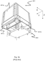
- Fig. 1 discloses a prior art automated storage and retrieval system 1 with a framework structure 100 and Figs. 2, 3a and 3b disclose three different prior art container handling vehicles 201,301,401 suitable for operating on such a system 1.
- the framework structure 100 comprises upright members 102 and a storage volume comprising storage columns 105 arranged in rows between the upright members 102.
- storage columns 105 storage containers 106, also known as bins, are stacked one on top of one another to form stacks 107.
- the members 102 may typically be made of metal, e.g. extruded aluminum profiles.
- the framework structure 100 of the automated storage and retrieval system 1 comprises a rail system 108 arranged across the top of framework structure 100, on which rail system 108 a plurality of container handling vehicles 201,301,401 may be operated to raise storage containers 106 from, and lower storage containers 106 into, the storage columns 105, and also to transport the storage containers 106 above the storage columns 105.
- the rail system 108 comprises a first set of parallel rails 110 arranged to guide movement of the container handling vehicles 201,301,401 in a first direction X across the top of the frame structure 100, and a second set of parallel rails 111 arranged perpendicular to the first set of rails 110 to guide movement of the container handling vehicles 201,301,401 in a second direction Y which is perpendicular to the first direction X.
- Containers 106 stored in the columns 105 are accessed by the container handling vehicles 201,301,401 through access openings 112 in the rail system 108.
- the container handling vehicles 201,301,401 can move laterally above the storage columns 105, i.e. in a plane which is parallel to the horizontal X-Y plane.
- the upright members 102 of the framework structure 100 may be used to guide the storage containers during raising of the containers out from and lowering of the containers into the columns 105.
- the stacks 107 of containers 106 are typically self-supporting.
- each storage column 105 can be identified by its X and Y coordinates.
- Each prior art container handling vehicle 201,301,401 comprises a storage compartment or space for receiving and stowing a storage container 106 when transporting the storage container 106 across the rail system 108.
- the storage space may comprise a cavity arranged internally within the vehicle body 201a,401a as shown in Figs. 2 and 3b and as described in e.g. WO2015/193278A1 and WO2019/206487A1 , the contents of which are incorporated herein by reference.
- Fig. 3a shows an alternative configuration of a container handling vehicle 301 with a cantilever construction.
- a container handling vehicle 301 with a cantilever construction.
- Such a vehicle is described in detail in e.g. NO317366 , the contents of which are also incorporated herein by reference.
- the cavity container handling vehicle 201 shown in Fig. 2 may have a footprint that covers an area with dimensions in the X and Y directions which is generally equal to the lateral extent of a storage column 105, e.g. as is described in WO2015/193278A1 , the contents of which are incorporated herein by reference.
- the term ⁇ lateral' used herein may mean 'horizontal'.
- WO2018/146304A1 illustrates a typical configuration of rail system 108 comprising rails and parallel tracks in both X and Y directions.
- columns 105 In the framework structure 100, a majority of the columns 105 are storage columns 105, i.e. columns 105 where storage containers 106 are stored in stacks 107. However, some columns 105 may have other purposes.
- columns 119 and 120 are such special-purpose columns used by the container handling vehicles 201,301,401 to drop off and/or pick up storage containers 106 so that they can be transported to an access station (not shown) where the storage containers 106 can be accessed from outside of the framework structure 100 or transferred out of or into the framework structure 100.
- such a location is normally referred to as a 'port' and the column in which the port is located may be referred to as a ⁇ port column' 119,120.
- the transportation to the access station may be in any direction that is horizontal, tilted and/or vertical.
- the storage containers 106 may be placed in a random or dedicated column 105 within the framework structure 100, then picked up by any container handling vehicle and transported to a port column 119,120 for further transportation to an access station.
- the transportation from the port to the access station may require movement along various different directions, by means such as delivery vehicles, trolleys or other transportation lines.
- the term 'tilted' means transportation of storage containers 106 having a general transportation orientation somewhere between horizontal and vertical.
- the access station may typically be a picking or a stocking station where product items are removed from or positioned into the storage containers 106.
- the storage containers 106 are normally not removed from the automated storage and retrieval system 1, but are returned into the framework structure 100 again once accessed.
- a port can also be used for transferring storage containers to another storage facility (e.g. to another framework structure or to another automated storage and retrieval system), to a transport vehicle (e.g. a train or a lorry), or to a production facility.
- a conveyor system comprising conveyors is normally employed to transport the storage containers between the port columns 119,120 and the access station.
- the conveyor system may be arranged to transfer storage containers 106 between different framework structures, e.g. as is described in WO2014/075937A1 , the contents of which are incorporated herein by reference.
- the operation also involves temporarily moving the above-positioned storage containers prior to lifting the target storage container 106 from the storage column 105.
- This step which is sometimes referred to as "digging" within the art, may be performed with the same container handling vehicle that is subsequently used for transporting the target storage container to the drop-off port column 119, or with one or a plurality of other cooperating container handling vehicles.
- the automated storage and retrieval system 1 may have container handling vehicles 201,301,401 specifically dedicated to the task of temporarily removing storage containers 106 from a storage column 105. Once the target storage container 106 has been removed from the storage column 105, the temporarily removed storage containers 106 can be repositioned into the original storage column 105. However, the removed storage containers 106 may alternatively be relocated to other storage columns 105.
- the access station disclosed in WO2020/074717 also has many moving or rotating components, particularly associated with the conveyors, that are prone to wear and regularly require maintenance.
- a further obj ective of the present invention is to reduce the complexity of the access station, particularly regarding the number of moving components.
- the present invention relates to a an automated storage and retrieval system comprising a framework structure, wherein the framework structure comprises:
- the framework structure comprises outer panels secured between at least some of the peripherical upright members and wherein the access station is insertable into and retrievable out from the access station compartment via a side opening in one of the panels.
- the present invention also relates to a an automated storage and retrieval system according any one of the above claims, wherein the access station compartment has a width being larger than a distance between two upright members, wherein the width is measured in a direction coinciding with or in a direction parallel with the distance.
- the width and the distance are measured perpendicular to the direction of horizontal movement of the storage container in the access station.
- the framework structure comprises a receptacle frame defining the access station compartment, wherein the receptacle frame is forming a support for a plurality of upright members.
- the receptacle frame comprises upright frame members and cross-members connected between the upright frame members.
- the access station compartment is located in the periphery of the framework structure.
- the access station is situated outside of the access station compartment during maintenance, repair and/or service of the access station.
- the access station comprises an access module comprising a frame, wherein the access station comprises wheels secured to the frame for rolling the access station into and out from the access station compartment via the side opening.
- the access station comprises:
- the main module is surrounding the side opening. Hence, the only way to access a storage container received within the main module is through the top cover.
- the main module is secured to the panel and/or to upright members of the framework structure.
- the main module is a wall hanging module.
- the main module is a floor standing module comprising for example legs or another type of base structure.
- the main module is a furniture-like structure, such as a cabinet.
- the access station comprises a top opening alignable below one of the columns when the access station is inserted into the access station compartment, wherein at least one of the container handling vehicles is configured to supply a storage container to the access station through the column and/or to retrieve a storage container from the access station through the column when the access station is inserted into the access station compartment and aligned with the column.
- the framework structure comprises horizontal members connected between the upright members at a height that permits the access station to be inserted into the access station compartment underneath the horizontal members.
- the access station comprises a jack for elevating an upper portion of the access station upwardly within the access station compartment.
- access station compartment comprises a roof portion.
- the roof portion may be formed by downwardly facing surfaces of the horizontal members.
- the top opening is located between horizontal members.
- the jack may be configured to elevate the access station up towards the roof portion within the access station compartment once inserted therein.
- the frame is defining a drawer compartment provided within the frame; wherein the access station comprises:
- the access station comprises a front opening through which the drawer moves between the presentation position and retracted position, wherein the front opening is alignable with a side opening of the access station compartment in the framework structure.
- the drawer front is aligned with the front opening when the drawer is in the retracted position.
- the vertical side guiding plates and the horizontal lower guiding plate may extend/protrude from the access station compartment when the access station is inserted into the access station compartment.
- a storage container retrievable from the drawer via the top opening and/or the drawer can receive a storage container via the top opening.
- the front position is located below the top opening when the drawer is in the retracted position and wherein the rear position is located below the top opening when the drawer is in the presentation position.
- the access station is configured to:
- the second actuator is configured to move the storage container from the front position to the rear position when the drawer is in the retracted position or when the drawer is moving from the presentation position to the retracted position.
- the frame comprises a guard defining an upper border of the front opening.
- the safety mechanism is configured to prevent an object from being squeezed between the drawer front and the guard during movement of the drawer from the presentation position to the retracted position.
- the safety mechanism comprises:
- the flap element is movably connected to a flap holding structure secured to the frame.
- the flap holding structure is a supporting structure for a user interface system.
- the support comprises rollers for supporting the storage container in the rear position.
- the support comprises a weight sensor for measuring a weight of the storage container when supporting the storage container in the front position.
- the second actuator comprises an electric motor and an actuating element movable by means of the electric motor.
- the drawer front and the guard are vertically aligned when the drawer is in the retracted position.
- the drawer comprises a container stop for preventing movement of the storage container from the front position towards the rear position when the drawer is in the presentation position.
- other parts of the framework structure comprises horizontal members.
- such horizontal members are integrated with the rail system.
- the system may comprise an initial number of access stations and an initial number of container handling vehicles.
- the capacity of the system may be increased by providing the side opening for the access station compartment in the panel and then inserting the access station. Before installation of the access station 10, the columns of the access station compartment may be used for stacking storage containers. Container handling vehicles may or may not be added as well.
- the access station compartment is located below at least one column of the framework structure.
- the column may be a port column, i.e. which are not intended for a stack of storage containers, or a storage column which are intended for a stack of storage containers.
- the term "access station” is a station enabling access to a storage container.
- the station is typically enabling access for an operator to the storage container, but may also enabling access for a robot, for example a picking robot, to the storage container.
- the access station may typically be a picking or a stocking station where product items are removed from or positioned into the storage container. In a picking or a stocking station, the storage containers are normally not removed from the automated storage and retrieval system, but are returned into the framework structure again once accessed.
- the present invention also relates to a method for installation and/or de-installation of an access station in an automated storage and retrieval system, wherein the method comprises the following steps:
- the step of inserting the access station comprises:
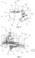
- the access station 10 comprises a top opening indicated as a dashed rectangle 26.
- the top opening 26 is provided in a horizontal plane.
- the access station 10 comprises an access opening 46 through which the content of the storage container 106 is accessible for the picker P.
- the access station 10 further comprises a first actuator 62 for moving the drawer 40 relative to the frame 21 between two positions referred to as a presentation position PP and a retracted position RP.
- the presentation position PP is shown in fig. 5 and 7a .
- the drawer 40 is protruding from the drawer compartment 25 and a storage container 106 is presented to a picker P.
- the retracted position RP is shown in fig. 7b and 7c .
- the drawer 40 is retracted within the drawer compartment 25 and hence, no storage container 106 is presented to the picker P.
- the access station 10 further comprises a second actuator 64.
- the second actuator 64 and other details of the access station 10 will be described in detail below.
- the access station 10 may also comprise a control system CS for controlling the first and second actuators 62, 64.
- the control system CS may be a part of the control system 500 for the automated storage and retrieval system, or the control system CS may be a separate control system in communication with the control system 500 for the automated storage and retrieval system.
- the drawer 40 comprises a drawer base 41 movably connected to the frame 21 and a drawer front 42.
- the drawer base 41 comprises a support 50 on which two storage containers 106 can be supported, as shown in fig. 7c and 7d .
- the position of the storage container 106 being located closest to the front 42 is referred to as a front position P1
- the position of the storage container 106 being located distant from the front 42 is referred to as a rear position P2.
- the electric motor 64a is here a linear motor. However, the electric motor 64a could also be a rotating motor for moving the actuating element 64b by means of a chain drive, a belt drive etc.
- the drawer 40 is provided within the drawer compartment 25 in the retracted position RP and at least partially protruding from the framework structure 100 in the presentation position PP.
- the storage container in the first position P1 is accessible for the picker P, while the storage container in the second position P2 is still provided withing the drawer compartment 25.
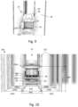
- the rear side RS is shown in fig. 10 .
- the frame 21 comprises lintels 102a for supporting upright members 102 of the framework structure 100.
- the frame 21 is forming a support for some of the upright members 102 of the framework structure 100.
- a row of storage columns 105A are located adjacent to the panels PA.
- the next row of storage columns is indicated as storage columns 105B, and the next row of storage columns again is referred to as storage columns 105C.
- the side guiding plates 22b and the lower guiding plate 22c are fixed in relation to the access station and the automated storage and retrieval system 1 and is therefore visible for the picker P and other persons working near the framework of the system 1. Hence, when the drawer 40 is moved from the retracted position RP to the presentation position PP, this movement will not create a surprising obstacle for nearby personnel, as the drawer front 42 is moved in the space between the vertical guiding plates 22b and the lower, horizontal guiding plate 22c.
- the frame 21 comprises a guard 22d defining an upper border of the front opening 22.
- the side guiding plates 22b, the lower guiding plate 22c and the guard 22d in the vertical plane P22 together define the borders of the front opening 22, as indicated in fig. 5 and in fig. 9 .
- the first actuator 62 is mounted to the lower cross plate 24c2 and comprises a linear motor 62a, an actuator element 62b and a guide 62c for guiding the linear movement of the actuator element 62b.
- the actuator element 62b is connected to the underside of the drawer 40, as shown in fig. 7c and fig. 10 .
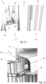
- the access station 10 comprises a safety mechanism 66 for preventing an object (typically the pickers fingers/hands) from being squeezed between the drawer front 42 and the guard 22d during movement of the drawer 40 from the presentation position PP to the retracted position RP.
- an object typically the pickers fingers/hands
- the safety mechanism 66 comprises a flap element 66a provided adjacent to, and on the front side FS of, the guard 22d, and a sensor 66b for sensing movement of the flap element 66a relative to the guard 22d.
- the flap element 66a is movably connected to a flap holding structure 66c secured to the frame 21 by means of one or more hinges 66d.
- the flap holding structure 66c is secured to the guard 22d.
- the flap element 66a is movably connected to the flap holding structure 66c by means of one or more hinges 66d.
- the flap holding structure 66c is a supporting structure for a user interface system 60, for example comprising a touch screen or other type of user interface.
- the sensor 66b may be an integrated circuit type of sensor, such as an accelerometer etc., connected to the first actuator 62.
- the sensor 66b may be a push-button type of security switch, which are activated by the movement of the flap element 66a. Sensors 66b of this type are known to a person skilled in the art.
- the sensor 66b When activated, the sensor 66b controls the first actuator 62 to stop the movement of the drawer or controls the first actuator 62 to move the drawer 40 out from the compartment 25 again.
- the sensor 66b may also control the second actuator 64 to stop the movement of the actuating element 64b or to move in the reverse direction.
- the sensor 66b may be connected directly to the first and/or second actuator 62,64. Alternatively, the sensor 66b is connected to the first and/or second actuator 62,64 via the control system CS.
- the first double-headed arrow indicates a first distance DA between the flap element 66a and the storage container in 106 in the front position P1. This distance is needed to be able to obtain access to the storage container 106 in the first position when the drawer 40 is in the presentation position PP and to be able to lift the storage container in the first position P1 up/down through the top opening 26 when the drawer is in the retracted position RP.
- the second double-headed arrow indicates a second distance DB between the storage container 106 in the front position P1 and storage container 106 in the rear position P2. This distance is needed to be able to be able to lift the storage container in the second position P2 up/down through the top opening 26 when the drawer is in the presentation position PP.
- the first distance DA is equal to, or substantially equal to the second distance DB.
- the plate 24d described above may allow storage containers to be stacked also in the third column 105C, the third column 105C having a reduced stacking height corresponding to the height H20 of the frame 21.
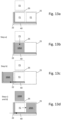
- a) ( fig. 13b ) the access station 10 receives a first storage container 106A.
- a container handling vehicle 201, 301 is controlled to pick a first storage container 106A from one of the storage columns 105 in the framework structure 100 and to lower it down into the front position P1 of the drawer 40. On its way down the storage column 105A, the first storage container 106A will pass the buffer position P3.
- a second step b) ( fig. 13c ), the first actuator 62 is controlled to move the drawer 40 to the presentation position PP.
- the first storage container 106A is presented to the picker P.
- step c) ( fig. 13d )
- the first actuator 62 is controlled to move the drawer 40 to the retracted position RP within the access module 20.
- step d the second actuator 64 is controlled to move the first storage container 106A from the front position P1 to the rear position P2 of the drawer 40.
- step c) may be performed before step d).
- step c) and d) may be performed simultaneously or substantially simultaneously.
- the safety mechanism will stop the movement of the drawer 40 if a finger/hand is located within the storage container on its way into the compartment 25 and will also stop the movement of the drawer 40 if a finger/hand is located between the front plate and the storage container on its way into the compartment 25.
- step c) and d the drawer 40 is in the retracted position RP and the first storage container 106A is in the rear position P2.
- the actuator element 64b will now return to its original position close to the front 42 of the drawer 40.
- the container handling vehicle 201, 301 may be controlled to pick a second storage container 106B from one of the storage columns 105 in the framework structure 100 and to lower it down to the buffer position P3.
- a next step e) ( fig. 13e ), the access station 10 receives the second storage container 106B from the buffer position P3.
- the second storage container 106B is lowered down into the front position P1 of the drawer 40.
- the container handling vehicle 201, 301 may hold the second storage container 106B stationary in the buffer position P3 while waiting for steps c) and d).
- the container handling vehicle 201, 301 may also be coordinated with the access station 10 so that there is no waiting time for the second storage container 106B in the buffer position P3.
- a next step f) ( fig. 13f ), the first actuator 62 is controlled to move the drawer 40 to the presentation position PP in which the second storage container 106B is presented to the picker P.
- the first storage container 106A is retrieved from the rear position P2 by means of a container handling vehicle 201, 301.
- a next step g) ( fig. 13h ), the first actuator 62 is controlled to move the drawer 40 to the retracted position RP within the access module 20.
- the second actuator 64 is controlled to move the second storage container 106B from the front position P1 to the rear position P2 of the drawer 40.
- steps g) and h) are similar to the above steps c) and d).
- the container handling vehicle 201, 301 may be controlled to pick a third storage container 106C from one of the storage columns 105 in the framework structure 100 and to lower it down to the buffer position P3.
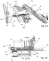
- the rear wheels 44 are running on top of the profile 81.
- the drawer In fig. 17 the drawer is in the presentation position (PP).
- the rear wheels 44 are located on the elevated profile section 81b, causing the rear part of the wheel connector member 83 to tilt upwardly, and hence causing the container stop element 82 to protrude up on the rear side of the storage container 106 in the front position P1. Movement of the storage container 106 from the front position to the rear position (for example by a person trying to push the storage container) is now prevented. It is also possible for the container stop element 82 to prevent the storage container 106 to be lifted up from the drawer in the presentation position (to prevent theft etc).
- the drawer is in the retracted position (RP).
- the rear wheels 44 are located on the lowered profile section 81a, causing the rear part of the wheel connector member 83 to tilt downwardly, and hence causing the container stop element 82 to retract down from the rear side of the storage container 106 in the front position P1. Movement of the storage container 106 from the front position to the rear position by means of the second actuator 64 is now allowed.
- the frame 21 is not supporting the upright members 102 from below.
- the access module 20 is one single independent access module with a self-supporting frame 21 provided with wheels 11.
- the framework structure 100 comprises an access station compartment 90 having a side opening 91 which can be covered by a panel (PA) when not in use.
- the access station 10 is then insertable into and retrievable from the access station compartment 90 by rolling the access station 10 into and out from the side opening 91.
- the access station 10 may comprise a jack for elevating an upper portion of the access station 10 upwardly within the access station compartment 90, for example up towards a roof portion 93 within the access station compartment 90, the roof portion 93 being defined by the downwardly facing surfaces of the horizontal members 103. It is also shown in fig. 14 that a support plate 92 is secured below the lower ends of the upright members 95a. The wheels 11 of the access station 10 are supported onto this support plate 92 when inserted into the access station compartment 90.
- receptacle frame 95 A similar embodiment of the receptacle frame 95 is shown in fig. 24a and fig. 24b . Also here, the receptacle frame 95 comprises upright frame members 95a and cross-members 95b. It is also here shown how the receptacle frame 95 is forming a support for a plurality of upright members 102 of the framework structure 100.
- the width D90 of the access station compartment 90 is larger than a distance D102 between two upright members 102.
- the upright frame members 102 are used to guide the storage containers vertically.
- the width D10 of the access station 10 must be wider than the distance D102 between two upright members 102.
- the width D90 and the distance D102 are measured perpendicular to the direction of horizontal movement HM of the storage container 106 in the access station 10 (as indicated in fig. 24a and fig. 24b ).
- an access station 10 comprising three modules.
- the first module is referred to as a main module 12 secured to the outside of the framework structure 100.
- the main module 12 receives a storage container 106 during a picking/supply operation.
- the main module 12 is surrounding the opening 91 to the access station compartment 90.
- the second module is a cover module 14 provided above the main module 12 for controlling access to the storage container 106 when received by the main module 12.
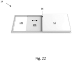
- the second module 14 is shown from below in fig. 22 and comprises an opening 14a which can be closed and opened by a movable cover 14b.
- the control system CS of the access station 10 is also integrated in the cover module 14.
- the actuator (not shown) operating the movable cover 14b is provided as a part of the control system CS. It should be noted that the movable cover 14b is provided with a safety mechanism 66 to prevent pinch injuries etc.
- the third module is a conveyor module 16.
- the conveyor module 16 comprises a conveyor belt, rollers and motors for powering the conveyor belt.
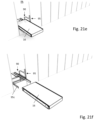
- the conveyor module 16 can easily be mounted to the receptacle frame 95 by means of drawer slides 95c ( fig. 21f ). As shown in fig. 24a , the conveyor module 16 will be located below the top opening 26. Hence, storage containers 106 will be lowered onto the conveyor module 16 via the column 105 and the top opening 26 by means of container handling vehicles similar to the embodiments described above, and storage containers 106 will be elevated from the conveyor module 16 through the top opening 26 and the column 105 by means of container handling vehicles similar to the embodiments described above.
- the control system CS is connected to the conveyor module 16 and also to the central control system 500 of the automated storage and retrieval system 1.
- the access station 10 further comprises a user interface 60 in the form of a computer terminal having a display, keyboard and mouse.
- the user interface 60 may be integrated in the cover module 14.
- fig. 21a-i the sequence of removing the access station 10 is shown.
- the cover module 14 is removed from the main module 12.
- the main module 12 is removed from the opening 91.
- the conveyor module 16 is retrieved from the opening 91.
- a new conveyor module 16 may now be inserted into the opening.
- the drawer slides 65c may be pushed into the compartment 90 and the opening 91 may be closed by means of a panel hatch.
- the vertical movement of the storage containers through the top opening 26 is performed by container handling vehicles 201, 301.
- a type of container lift may be used to move the storage containers vertically to and from the access station 10.
- the access station 10 occupies one storage column 105A for vertical transportation of storage containers, and two other storage columns 105B, 105C has reduced storage capacity due to the footprint areas A20, A40.
- One such possible safety mechanism is a movement detection type of sensor, for example a photoelectric sensor for sensing whether or not a finger/hand is present in the area close to the access opening 46 and or the front opening 22 during movement of the drawer 40 towards the retracted position RP.
- fig. 23 Here it is shown several access stations 10 of the above type, mounted adjacent to each other. As shown, the orientation of the openings 14a differ from each other due to the orientation of the storage containers 106 within the framework structure 100. The access stations on the left side receives the narrow side of the storage containers while the access stations on the right side receives the wide side of the storage containers.
Landscapes
- Engineering & Computer Science (AREA)
- Mechanical Engineering (AREA)
- Physics & Mathematics (AREA)
- Mathematical Physics (AREA)
- Warehouses Or Storage Devices (AREA)
Applications Claiming Priority (3)
| Application Number | Priority Date | Filing Date | Title |
|---|---|---|---|
| NO20201433A NO346540B1 (en) | 2020-12-23 | 2020-12-23 | An access station for an automated storage and retrieval system and method for using same |
| PCT/EP2021/087074 WO2022136423A1 (en) | 2020-12-23 | 2021-12-21 | Automated storage and retrieval system comprising an access station compartment |
| EP21843723.4A EP4267495B1 (de) | 2020-12-23 | 2021-12-21 | Automatisiertes regalbedienungssystem mit einem zugangsstationsfach |
Related Parent Applications (2)
| Application Number | Title | Priority Date | Filing Date |
|---|---|---|---|
| EP21843723.4A Division EP4267495B1 (de) | 2020-12-23 | 2021-12-21 | Automatisiertes regalbedienungssystem mit einem zugangsstationsfach |
| EP21843723.4A Division-Into EP4267495B1 (de) | 2020-12-23 | 2021-12-21 | Automatisiertes regalbedienungssystem mit einem zugangsstationsfach |
Publications (2)
| Publication Number | Publication Date |
|---|---|
| EP4516699A2 true EP4516699A2 (de) | 2025-03-05 |
| EP4516699A3 EP4516699A3 (de) | 2025-05-07 |
Family
ID=79602256
Family Applications (3)
| Application Number | Title | Priority Date | Filing Date |
|---|---|---|---|
| EP21843681.4A Pending EP4267494A1 (de) | 2020-12-23 | 2021-12-20 | Zugangsstation für ein automatisiertes regalbedienungssystem und verfahren zu deren verwendung |
| EP24218019.8A Pending EP4516699A3 (de) | 2020-12-23 | 2021-12-21 | Automatisiertes regalbedienungssystem mit einem zugangsstationsfach |
| EP21843723.4A Active EP4267495B1 (de) | 2020-12-23 | 2021-12-21 | Automatisiertes regalbedienungssystem mit einem zugangsstationsfach |
Family Applications Before (1)
| Application Number | Title | Priority Date | Filing Date |
|---|---|---|---|
| EP21843681.4A Pending EP4267494A1 (de) | 2020-12-23 | 2021-12-20 | Zugangsstation für ein automatisiertes regalbedienungssystem und verfahren zu deren verwendung |
Family Applications After (1)
| Application Number | Title | Priority Date | Filing Date |
|---|---|---|---|
| EP21843723.4A Active EP4267495B1 (de) | 2020-12-23 | 2021-12-21 | Automatisiertes regalbedienungssystem mit einem zugangsstationsfach |
Country Status (10)
| Country | Link |
|---|---|
| US (2) | US12583673B2 (de) |
| EP (3) | EP4267494A1 (de) |
| JP (2) | JP7819190B2 (de) |
| KR (2) | KR20230119231A (de) |
| CN (3) | CN116745219B (de) |
| CA (2) | CA3197569A1 (de) |
| ES (1) | ES3054798T3 (de) |
| NO (1) | NO346540B1 (de) |
| PL (1) | PL4267495T3 (de) |
| WO (2) | WO2022136299A1 (de) |
Families Citing this family (12)
| Publication number | Priority date | Publication date | Assignee | Title |
|---|---|---|---|---|
| US20230406639A1 (en) * | 2022-04-29 | 2023-12-21 | Kenton Brett | System and method for local tube transport |
| NO20220878A1 (en) * | 2022-08-12 | 2024-02-13 | Autostore Tech As | An automated storage and retrieval system having a container transfer apparatus, and a method thereof |
| NO347965B1 (en) * | 2022-10-28 | 2024-06-03 | Autostore Tech As | A device and method for inserting storage containers into an automated storage and retrieval system |
| NO20221406A1 (en) * | 2022-12-23 | 2024-06-24 | Autostore Tech As | Method, system and computer program product for moving a storage container |
| JP2026509185A (ja) | 2023-02-27 | 2026-03-17 | オートストアー テクノロジー アーエス | 保管コンテナを移動させるためのアクチュエータ |
| NO20230191A1 (en) | 2023-02-27 | 2024-08-28 | Autostore Tech As | Access station for an automated storage and retrieval system |
| NO20230482A1 (en) * | 2023-04-28 | 2024-10-29 | Autostore Tech As | Access station with stopper mechanism |
| NO348399B1 (en) | 2023-06-01 | 2025-01-06 | Autostore Tech As | A container transfer station, a storage system and a method for buffering storage container in a storage system |
| GB2641904A (en) * | 2024-06-17 | 2025-12-24 | Ocado Innovation Ltd | Inventory handling station assembly |
| EP4703291A1 (de) * | 2024-08-27 | 2026-03-04 | AutoStore Technology AS | Container-zugangsstation |
| EP4703294A1 (de) * | 2024-08-29 | 2026-03-04 | AutoStore Technology AS | Zugangsstation |
| EP4714863A1 (de) * | 2024-09-18 | 2026-03-25 | AutoStore Technology AS | Fördersystem |
Citations (6)
| Publication number | Priority date | Publication date | Assignee | Title |
|---|---|---|---|---|
| WO2014075937A1 (en) | 2012-11-13 | 2014-05-22 | Jakob Hatteland Logistics As | Storage system |
| WO2014090684A1 (en) | 2012-12-10 | 2014-06-19 | Jakob Hatteland Logistics As | Robot for transporting storage bins |
| WO2015193278A1 (en) | 2014-06-19 | 2015-12-23 | Jakob Hatteland Logistics As | Robot for transporting storage bins |
| WO2018146304A1 (en) | 2017-02-13 | 2018-08-16 | Autostore Technology AS | Rail arrangement for a storage system |
| WO2019206487A1 (en) | 2018-04-25 | 2019-10-31 | Autostore Technology AS | Container handling vehicle with first and second sections and lifting device motor in second section |
| WO2020074717A1 (en) | 2018-10-12 | 2020-04-16 | Autostore Technology AS | Access station for picking storage containers |
Family Cites Families (39)
| Publication number | Priority date | Publication date | Assignee | Title |
|---|---|---|---|---|
| US2499498A (en) * | 1947-04-29 | 1950-03-07 | Jr John Hays Hammond | Mobile housing unit |
| GB1181434A (en) * | 1967-02-03 | 1970-02-18 | Elliotts Of Peterborough Ltd | Improvements in or relating to Prefabricated Buildings and their Assembly |
| GB1449266A (en) * | 1973-11-19 | 1976-09-15 | Supreme Equip & Syst | Load handling mechanism for a storage and retrieval system |
| JPS6055403B2 (ja) * | 1980-01-29 | 1985-12-05 | 株式会社伊藤喜工作所 | 物品の自動入出庫装置 |
| DE4218615C1 (de) * | 1992-06-05 | 1993-07-15 | Nukem Gmbh, 8755 Alzenau, De | |
| DE4412634A1 (de) | 1994-04-13 | 1995-10-19 | Zambelli Stahlmoebel Gmbh & Co | Lagergutausgabeeinrichtung für Paternosterschränke |
| JPH08198407A (ja) * | 1995-01-27 | 1996-08-06 | Kumahira Safe Co Inc | ファイルフォルダの自動入出庫装置 |
| US5957558A (en) * | 1997-07-23 | 1999-09-28 | Quade; Robert C. | Combination drawer/shelf storage unit |
| US6301776B1 (en) * | 1998-05-15 | 2001-10-16 | Samsung Electronics Co., Ltd. | System and method for assembling an outdoor unit of a dual-unit type air conditioner |
| JP2000345724A (ja) * | 1999-06-03 | 2000-12-12 | Masafumi Miyamoto | アミューズメント施設、アミューズメント施設用コンテナ及びアミューズメント設備の設置方法 |
| NO317366B1 (no) | 1999-07-01 | 2004-10-18 | Autostore As | Lagringsanlegg med fjernstyrte vogner med to hjulsett og heisinnretning for drift på skinner anlagt i kryss over kolonner av lagringsenheter som er adskilt med vertikale profilstolper |
| US6709225B1 (en) * | 2000-02-18 | 2004-03-23 | Asyst Technologies, Inc. | System for installation, maintenance and removal of minienvironment components |
| US20040101386A1 (en) * | 2002-11-22 | 2004-05-27 | Bellheimer Metallwerk Gmbh | Vertical carousel with top and side access stations |
| JP2008050064A (ja) * | 2006-08-22 | 2008-03-06 | Toa Holdings Inc | ピッキングシステムの部品棚の引出ユニット |
| US8103379B2 (en) * | 2009-01-09 | 2012-01-24 | Automed Technologies, Inc. | Medication cabinetry |
| JP5212165B2 (ja) * | 2009-02-20 | 2013-06-19 | 東京エレクトロン株式会社 | 基板処理装置 |
| JP5348491B2 (ja) * | 2009-08-24 | 2013-11-20 | 株式会社ダイフク | 倉庫設備 |
| US20110255940A1 (en) * | 2010-04-20 | 2011-10-20 | Wildfeuer Jeffrey T | Cartridge-type-loading transit case system and method for loading electronic racks in a receiver rack |
| CN104495181B (zh) | 2014-11-25 | 2017-02-01 | 北京理工大学 | 物品高密度存放的自动存储及提取系统 |
| WO2016166324A1 (en) * | 2015-04-15 | 2016-10-20 | Ocado Innovation Limited | System and method for configuration of buildings or storage |
| DE102015218380A1 (de) * | 2015-09-24 | 2017-03-30 | Gebr. Willach Gmbh | Beladevorrichtung für eine Warenübergabevorrichtung eines automatischen Warenlagers |
| US10730078B2 (en) * | 2015-12-04 | 2020-08-04 | Berkshire Grey, Inc. | Systems and methods for dynamic sortation of objects |
| NO342458B1 (en) * | 2016-01-14 | 2018-05-21 | Autostore Tech As | A storage system and method for storing and transporting bins |
| FR3049201B1 (fr) | 2016-03-24 | 2018-03-09 | Solystic | Module de sortie de tri pour machine de tri postal |
| NO344609B1 (en) * | 2016-06-06 | 2020-02-10 | Autostore Tech As | Conveyor with tilt function |
| NO344898B1 (en) * | 2016-06-10 | 2020-06-22 | Autostore Tech As | Storage system with drawer port |
| CA3058936C (en) * | 2017-04-18 | 2022-03-08 | Alert Innovation Inc. | Picking workstation with mobile robots & machine vision verification of each transfers performed by human operators |
| NO343848B1 (en) * | 2017-06-23 | 2019-06-24 | Autostore Tech As | Automated Storage and Retrieval System Comprising a Container Handling Station |
| NO344465B1 (en) * | 2017-10-20 | 2019-12-23 | Autostore Tech As | Bin holding Device and method of arranging a top edge of a storage bin at a predetermined level in the bin holding device |
| FR3077514B1 (fr) | 2018-02-02 | 2020-01-17 | Etablissements Oger | Dispositif de manutention de pieces stockees sur palettes positionnable au voisinage d'un centre d'usinage |
| NO344302B1 (en) * | 2018-04-25 | 2019-10-28 | Autostore Tech As | Automated storage and retrieval system comprising a relay module and a method of operating such a system |
| MX2020013280A (es) * | 2018-06-08 | 2021-02-22 | Attabotics Inc | Sistemas mejorados de almacenamiento y recuperacion. |
| NO344988B1 (en) * | 2018-11-05 | 2020-08-10 | Autostore Tech As | A station for providing access to contents in a storage container |
| NO348659B1 (en) * | 2019-03-29 | 2025-04-22 | Autostore Tech As | A system for providing secure storing and retrieving of personal storage containers via an interaction area |
| WO2020210558A1 (en) * | 2019-04-09 | 2020-10-15 | Rushlook, Inc. | Logistics tower |
| CN210680847U (zh) * | 2019-09-10 | 2020-06-05 | 三明市金圣特种钢有限公司 | 一种汽车铸件搬运装置 |
| CN111361913A (zh) * | 2020-04-24 | 2020-07-03 | 深圳厨奇自胜智能装备技术有限公司 | 一种碗具存取机器人以及补碗车 |
| EP3929111B1 (de) * | 2020-06-24 | 2025-08-13 | Tata Consultancy Services Limited | Vorrichtung und verfahren zum verpacken von heterogenen gegenständen |
| FR3113663B1 (fr) * | 2020-08-31 | 2022-09-09 | Exotec | Station de présentation de conteneurs |
-
2020
- 2020-12-23 NO NO20201433A patent/NO346540B1/en unknown
-
2021
- 2021-12-20 CA CA3197569A patent/CA3197569A1/en active Pending
- 2021-12-20 KR KR1020237024477A patent/KR20230119231A/ko active Pending
- 2021-12-20 CN CN202180087184.8A patent/CN116745219B/zh active Active
- 2021-12-20 CN CN202511980386.1A patent/CN121672071A/zh active Pending
- 2021-12-20 EP EP21843681.4A patent/EP4267494A1/de active Pending
- 2021-12-20 US US18/037,678 patent/US12583673B2/en active Active
- 2021-12-20 JP JP2023529012A patent/JP7819190B2/ja active Active
- 2021-12-20 WO PCT/EP2021/086850 patent/WO2022136299A1/en not_active Ceased
- 2021-12-21 JP JP2023537981A patent/JP2024501249A/ja active Pending
- 2021-12-21 EP EP24218019.8A patent/EP4516699A3/de active Pending
- 2021-12-21 ES ES21843723T patent/ES3054798T3/es active Active
- 2021-12-21 PL PL21843723.4T patent/PL4267495T3/pl unknown
- 2021-12-21 WO PCT/EP2021/087074 patent/WO2022136423A1/en not_active Ceased
- 2021-12-21 EP EP21843723.4A patent/EP4267495B1/de active Active
- 2021-12-21 CN CN202180085914.0A patent/CN116685543A/zh active Pending
- 2021-12-21 CA CA3199932A patent/CA3199932A1/en active Pending
- 2021-12-21 KR KR1020237024486A patent/KR20230119232A/ko active Pending
- 2021-12-21 US US18/256,736 patent/US20240025643A1/en active Pending
Patent Citations (6)
| Publication number | Priority date | Publication date | Assignee | Title |
|---|---|---|---|---|
| WO2014075937A1 (en) | 2012-11-13 | 2014-05-22 | Jakob Hatteland Logistics As | Storage system |
| WO2014090684A1 (en) | 2012-12-10 | 2014-06-19 | Jakob Hatteland Logistics As | Robot for transporting storage bins |
| WO2015193278A1 (en) | 2014-06-19 | 2015-12-23 | Jakob Hatteland Logistics As | Robot for transporting storage bins |
| WO2018146304A1 (en) | 2017-02-13 | 2018-08-16 | Autostore Technology AS | Rail arrangement for a storage system |
| WO2019206487A1 (en) | 2018-04-25 | 2019-10-31 | Autostore Technology AS | Container handling vehicle with first and second sections and lifting device motor in second section |
| WO2020074717A1 (en) | 2018-10-12 | 2020-04-16 | Autostore Technology AS | Access station for picking storage containers |
Also Published As
| Publication number | Publication date |
|---|---|
| PL4267495T3 (pl) | 2026-02-09 |
| JP7819190B2 (ja) | 2026-02-24 |
| CN116745219A (zh) | 2023-09-12 |
| CN116745219B (zh) | 2026-01-09 |
| US20230406630A1 (en) | 2023-12-21 |
| CN121672071A (zh) | 2026-03-17 |
| KR20230119232A (ko) | 2023-08-16 |
| CA3199932A1 (en) | 2022-06-30 |
| NO346540B1 (en) | 2022-09-26 |
| JP2024500010A (ja) | 2024-01-04 |
| EP4267494A1 (de) | 2023-11-01 |
| EP4516699A3 (de) | 2025-05-07 |
| CN116685543A (zh) | 2023-09-01 |
| EP4267495C0 (de) | 2025-09-03 |
| EP4267495A1 (de) | 2023-11-01 |
| WO2022136423A1 (en) | 2022-06-30 |
| ES3054798T3 (en) | 2026-02-06 |
| KR20230119231A (ko) | 2023-08-16 |
| US12583673B2 (en) | 2026-03-24 |
| JP2024501249A (ja) | 2024-01-11 |
| US20240025643A1 (en) | 2024-01-25 |
| WO2022136299A1 (en) | 2022-06-30 |
| EP4267495B1 (de) | 2025-09-03 |
| NO20201433A1 (en) | 2022-06-24 |
| CA3197569A1 (en) | 2022-06-30 |
Similar Documents
| Publication | Publication Date | Title |
|---|---|---|
| EP4267495B1 (de) | Automatisiertes regalbedienungssystem mit einem zugangsstationsfach | |
| JP7445605B2 (ja) | リレーモジュールを含む自動格納及び回収システム並びにそのようなシステムを動作させる方法 | |
| EP4563499A2 (de) | Automatisiertes regalbedienungssystem mit einer lagerbehälterhebeanordnung | |
| CN113165803A (zh) | 用于拾取储存容器的存取站 | |
| EP4553010A1 (de) | Servicefahrzeug mit einem fahrzeugstift | |
| EP3807182B1 (de) | Liefersystem mit einem zugangspunkt und verfahren zum zugang zu einem zugangspunkt des liefersystems | |
| EP4330164B1 (de) | Doppelendige zugangsstation für ein automatisiertes regalbedienungssystem und verfahren zu deren verwendung | |
| EP4422992B1 (de) | Zugangsstation mit sicherheitsmechanismus | |
| JP6740439B1 (ja) | 荷物保管システム | |
| EP4371910A1 (de) | Verfahren und vorrichtung zum lagern und entnehmen von lebensmittel-lebensstücken | |
| HK40099682A (zh) | 包括存取站隔室的自动储存和取出系统 | |
| EP4419451B1 (de) | Anordnung, speichermodul und automatisiertes regalbedienungssystem | |
| HK40099650A (zh) | 用於自动储存和取出系统的存取站及其使用方法 | |
| CN117985388A (zh) | 模块化设备、计算机化方法和将装货箱进行移动的方法 | |
| WO2024256698A1 (en) | Grid connector | |
| HK40078707A (en) | Container accessing station with lifting device | |
| JP2026509184A (ja) | 自動保管及び回収システムのためのアクセスステーション | |
| WO2025157371A1 (en) | Automated storage and retrieval system | |
| HK40044329B (en) | Container accessing station with lifting device | |
| HK40044329A (en) | Container accessing station with lifting device |
Legal Events
| Date | Code | Title | Description |
|---|---|---|---|
| PUAI | Public reference made under article 153(3) epc to a published international application that has entered the european phase |
Free format text: ORIGINAL CODE: 0009012 |
|
| STAA | Information on the status of an ep patent application or granted ep patent |
Free format text: STATUS: REQUEST FOR EXAMINATION WAS MADE |
|
| 17P | Request for examination filed |
Effective date: 20241206 |
|
| AC | Divisional application: reference to earlier application |
Ref document number: 4267495 Country of ref document: EP Kind code of ref document: P |
|
| AK | Designated contracting states |
Kind code of ref document: A2 Designated state(s): AL AT BE BG CH CY CZ DE DK EE ES FI FR GB GR HR HU IE IS IT LI LT LU LV MC MK MT NL NO PL PT RO RS SE SI SK SM TR |
|
| REG | Reference to a national code |
Ref country code: DE Ref legal event code: R079 Free format text: PREVIOUS MAIN CLASS: B65G0001137000 Ipc: B65G0001040000 |
|
| PUAL | Search report despatched |
Free format text: ORIGINAL CODE: 0009013 |
|
| AK | Designated contracting states |
Kind code of ref document: A3 Designated state(s): AL AT BE BG CH CY CZ DE DK EE ES FI FR GB GR HR HU IE IS IT LI LT LU LV MC MK MT NL NO PL PT RO RS SE SI SK SM TR |
|
| RIC1 | Information provided on ipc code assigned before grant |
Ipc: B65G 1/137 20060101ALI20250331BHEP Ipc: B65G 1/06 20060101ALI20250331BHEP Ipc: B65G 1/04 20060101AFI20250331BHEP |
|
| STAA | Information on the status of an ep patent application or granted ep patent |
Free format text: STATUS: EXAMINATION IS IN PROGRESS |
|
| 17Q | First examination report despatched |
Effective date: 20260316 |
|
| RAP3 | Party data changed (applicant data changed or rights of an application transferred) |
Owner name: AUTOSTORE TECHNOLOGY AS |