EP4403434A1 - Innenschiebetür für ein schienenfahrzeug mit einfahrbarer abdeckung - Google Patents
Innenschiebetür für ein schienenfahrzeug mit einfahrbarer abdeckung Download PDFInfo
- Publication number
- EP4403434A1 EP4403434A1 EP23220752.2A EP23220752A EP4403434A1 EP 4403434 A1 EP4403434 A1 EP 4403434A1 EP 23220752 A EP23220752 A EP 23220752A EP 4403434 A1 EP4403434 A1 EP 4403434A1
- Authority
- EP
- European Patent Office
- Prior art keywords
- door
- door leaf
- cover
- leaf
- sliding door
- Prior art date
- Legal status (The legal status is an assumption and is not a legal conclusion. Google has not performed a legal analysis and makes no representation as to the accuracy of the status listed.)
- Granted
Links
Images


Classifications
-
- B—PERFORMING OPERATIONS; TRANSPORTING
- B61—RAILWAYS
- B61D—BODY DETAILS OR KINDS OF RAILWAY VEHICLES
- B61D19/00—Door arrangements specially adapted for rail vehicles
- B61D19/003—Door arrangements specially adapted for rail vehicles characterised by the movements of the door
- B61D19/005—Door arrangements specially adapted for rail vehicles characterised by the movements of the door sliding
-
- B—PERFORMING OPERATIONS; TRANSPORTING
- B61—RAILWAYS
- B61D—BODY DETAILS OR KINDS OF RAILWAY VEHICLES
- B61D19/00—Door arrangements specially adapted for rail vehicles
- B61D19/02—Door arrangements specially adapted for rail vehicles for carriages
Definitions
- the invention relates to a door device for the interior of a rail vehicle with at least one sliding door with at least one door leaf.
- WO 2021/239366 A1 now teaches a door device for the interior of a rail vehicle with at least one double-leaf sliding door.
- WO 2014/106581 A1 discloses a door device of a rail vehicle with an external sliding door, which has a cutout in a lower region of a door leaf, which is closed by a folded-in folding step in a closed position of the external sliding door.
- the invention is based on the task of further optimizing the use of space.
- a door device for a rail vehicle, in particular for an interior of the rail vehicle, comprises at least one sliding door with at least one door leaf, wherein the at least one door leaf has a cutout in the region of a secondary closing edge of the at least one door leaf for receiving a fixed component of the rail vehicle in an open position of the sliding door, wherein a cover is movably arranged on the at least one door leaf, which covers the cutout in a closed position of the sliding door.
- a door device is designed to be particularly suitable for an interior of a rail vehicle for passenger transport.
- the interior of a rail vehicle is delimited on the outside by a ceiling, two side walls and a floor.
- An interior door is used to divide the interior and thus to separate a first part of the interior, for example a passenger area, from a second part, for example a passage area or an entry area.
- Single or double-leaf sliding doors can also be used for this purpose.
- the sliding door is in particular an interior sliding door. According to one embodiment, it can be designed with one leaf, i.e. it has exactly one sliding door leaf.
- the door leaf also called a door wing, can be aligned vertically as intended and can be moved in the transverse direction of the vehicle.
- the invention relates to a passenger transport vehicle, in particular a track-bound vehicle, for example a rail vehicle, in particular for public passenger transport, comprising at least one door device according to the invention.
- the door device is provided in particular in an interior of the public passenger transport vehicle between two interior parts, for example to separate two passenger compartments.
- the door device then acts as an interior door.
- the door leaf plane runs vertically in the transverse direction of the vehicle, for example. The door leaf or leaves can then be moved in the transverse direction of the vehicle.
- the cutout in the door leaf is located in particular in the area of a secondary closing edge opposite the main closing edge.
- the main closing edge of the door leaf is the closing edge whose distance from the parallel counter-closing edge of a door frame determines the opening width of the door device.
- the rear secondary closing edge of the door leaf is opposite the main closing edge and runs in particular parallel to it.
- a lower secondary closing edge closes the door leaf in the intended direction downwards
- an upper secondary closing edge closes the door leaf in the intended direction upwards.
- the cutout in the door leaf affects both the rear secondary closing edge of the door leaf and the lower and/or upper secondary closing edge.
- the cutout is used to accommodate a fixed component of the rail vehicle when the sliding door is in an open position, i.e. when the door leaf is pushed open.
- a sloping ceiling area or a support can be accommodated as a fixed component of the rail vehicle in an upper area of the door leaf, or a base or another frame part can be accommodated as a fixed component of the rail vehicle in a lower area of the door leaf.
- the fixed component of the rail vehicle does not then block the sliding door from opening completely.
- the sliding door can be opened to the required width despite the fixed component of the rail vehicle.
- the installation of a sliding door does not have to be dispensed with, regardless of the reduced installation space.
- the movable cover for the cutout in the door leaf is movably arranged on the door leaf and designed such that it covers the cutout in the door leaf, in particular completely, when the sliding door is in the closed position.
- the cover for the cutout in the door leaf is movably arranged on the door leaf such that it frees up the cutout when the sliding door is in the open position to accommodate the fixed component of the rail vehicle.
- the movable cover for the cutout in the door leaf is at least partially moved away from the cutout in the door leaf when the sliding door is in the open position to accommodate the fixed component of the rail vehicle. This can be done by various mechanisms, as explained further below.
- the movable cover enables a sliding door to be used in tight spaces.
- the sliding door When the sliding door is opened from the closed position to the open position, it is moved away from the cutout so that when the sliding door is open, it clears the cutout to accommodate the fixed component of the rail vehicle.
- the movable cover could also be said to be in an open state.
- the movable cover is again moved in front of or over the cutout in the door leaf so that it covers it when the sliding door is closed.
- the cover is arranged completely in front of or over the cutout. The cover is in the closed state. This prevents the cutout from being visible from the outside.
- the cover can also be used to seal it off, e.g. against drafts.
- the movable cover is arranged displaceably on the door leaf.
- the movable cover is arranged rotatably on the door leaf.
- the cover When the sliding door is in the closed position, the cover is preferably aligned parallel to the door leaf. In addition, it is advantageously moved in a plane parallel to the door leaf. It is then designed accordingly and arranged on the door leaf. For example, it is arranged parallel to the plane of the door leaf, in or over the door leaf, and can be moved on it. The displacement takes place in particular in a direction parallel to an upper or lower secondary closing edge of the sliding door - i.e. in a horizontal direction in the intended installation position of the sliding door and thus also in or in particular against the direction of displacement of the door leaf of the sliding door. It is also conceivable for the cover to rotate in a plane parallel to the door leaf.
- the rotation can take place, for example, about an axis perpendicular to the plane of the door leaf, in or over the door leaf.
- the cover can also rotate about an axis parallel to the door leaf, in particular vertically in the intended orientation of the door leaf. In the latter case, the cover would be pivoted relative to the door leaf, so to speak.
- the cover partially covers the door leaf when the sliding door is in the open position. The cover is moved over the door leaf.
- the door leaf covers the cover in sections when the sliding door is in the open position.
- the cover is moved into the door leaf.
- the door leaf can have a corresponding cavity into which the cover is pushed.
- the door leaf covers the pushed-in cover on both sides.
- the door leaf can also have a one-sided step-shaped recess in which the cover is accommodated when the sliding door is in the open position.
- the recess causes, for example, a step in the door leaf that is open to the rear secondary closing edge and to the upper or lower secondary closing edge.
- the door leaf and the cover accommodated in the recess simultaneously cover each other at least partially on one side.
- the recess can be formed complementarily to the cover, so that the cover runs flush with the surface of the door leaf received in the recess.
- the cover is pre-tensioned against the door leaf.
- the door device comprises a compression spring between the door leaf and the cover.
- the pre-tension for example by the compression spring, causes a movement of the cover without any further external force acting on the cover from the open state of the cover, in which it exposes the cutout in an open position of the sliding door to accommodate the fixed component of the rail vehicle, in particular in the open position of the sliding door, to the closed state of the cover, in which the cover covers the cutout in the door leaf, in particular in the closed position of the sliding door.
- This restoring force can be introduced into the cover via the fixed component of the rail vehicle. It is applied by a force acting on the door leaf to open the sliding door from the closed position to the open position.
- This force for opening the sliding door can be applied to the door leaf manually or by a door drive, for example an electric motor or pneumatic drive.
- the door device has a suitable door drive. This is dimensioned sufficiently strong to move the door leaf and overcome the preload, in particular the spring preload.
- the door device comprises a locking element, in particular a mechanical one, which is in particular attached to the door leaf which blocks movement of the cover in the closed position of the sliding door.
- the movable cover is thus locked in the closed position of the sliding door. This prevents the cover from moving when the sliding door is in the closed position.
- the door leaf can have at least one guide rail in the area of the cutout, by means of which the cover is arranged displaceably on the door leaf.
- the guide rail is arranged parallel to the plane of the door leaf and serves to guide the displaceable cover.
- the cover can be displaced along the guide rail.
- the guide rail can be designed as a straight guide, in particular as a linear guide, and in a further development comprises at least one sliding or running body guided along the at least one guide rail.
- the guide rails can be designed as profile rails and the sliding or running bodies as bushings. At least one roller carriage is advantageously used as the running body.
- the guide rails can also be designed as open hollow rails with internally mounted rollers as the running body.
- the door leaf comprises a door stopper which can be moved linearly to the door leaf, which door stopper is designed to rest against a stop of a fixed component of the rail vehicle, at least in the open position of the sliding door, wherein the door stopper is pre-tensioned against the door leaf in such a way that it is moved away from the door leaf in the closed position of the sliding door and is moved towards the door leaf in the open position of the sliding door while resting against the stop, wherein it is designed to release the locking element when moved towards the door leaf.
- the door stopper which can be moved linearly to the door leaf is mounted so as to be movable, for example, in a groove or in a cavity in the door leaf.
- the locking element is wedge-shaped and vertically displaceable against the door leaf, in particular pre-tensioned by means of a compression spring
- the doorstop is rod-shaped with a wedge-shaped tip which interacts with the wedge-shaped locking element in such a way that when the doorstop is pushed out, the locking element is released and, in particular due to the pre-tension, is moved towards the cover and rests against a stop on the cover for the locking element and thus blocks movement of the cover and when the doorstop is pushed in, the wedge-shaped tip of the doorstop initially moves the wedge-shaped locking element away from the cover, in particular against the pre-tension, and thus releases movement of the cover and the doorstop blocks movement of the locking element towards the cover.
- the cutout is arranged in the area of the rear and lower secondary closing edge of the door leaf for receiving a fixed base of the rail vehicle in an open position of the sliding door, wherein the movable cover is arranged displaceably on the door leaf so that it covers the cutout in a closed position of the sliding door, in particular completely, and in an open position of the sliding door it releases the cutout for receiving the fixed component of the rail vehicle.
- the displaceable cover In the open position of the sliding door, the displaceable cover is displaced away from the cutout for receiving the base, in particular parallel to the lower secondary closing edge of the door leaf, for example into a cavity. in the door leaf or via a stepped recess in the door leaf.
- the fixed component of the rail vehicle can also be part of the door device.
- the door device can also be part of a frame of the door device.
- the cutout in the door leaf is further developed to complement the fixed component of the rail vehicle, for example the base.
- the base can include the stop for the doorstop.
- the door device can have a guide rail for linear guidance of the door leaf, which guide rail is arranged, for example, in the floor or ceiling of the rail vehicle, wherein the guide rail is designed to guide the movable cover.
- the movable cover is then also designed to be suitable to be guided by the guide rail.
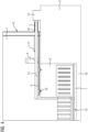
- a door device according to the invention is shown schematically in the closed position.
- the door device comprises an interior sliding door for a rail vehicle for dividing the interior of the rail vehicle, with at least one door leaf 1 that can be moved transversely to the direction of travel of the rail vehicle.
- the door leaf 1 has, in an area of a rear secondary closing edge 12 and a lower secondary closing edge 12 of the door leaf 1, a cover 2 which can be moved relative to the door leaf 1 and which, in the closed position of the sliding door illustrated here, covers a cutout in the door leaf 1 for receiving a fixed component of the rail vehicle, here a base 3, in an open position of the sliding door.
- a door stop 5 of the sliding door that can be moved relative to the door leaf 1 and a stop 13 for the door stop 5 on the base 3 can be seen, as well as an upper guide rail 8 for guiding the door leaf 1 in the ceiling area of the rail vehicle and a counter closing edge 14 of a door frame of the rail vehicle that is parallel to a main closing edge 9 of the door leaf 1.
- a lower guide rail 7 can also be provided for guiding the door leaf 1 in the floor 19 of the rail vehicle.
- the lower guide rail 7 for guiding the door leaf 1 in the floor 19 of the rail vehicle can also simultaneously serve to guide the sliding cover 2.
- Cover 2 and door leaf 1 are then designed to be appropriate in the area of their respective lower edges, in particular complementary, to the lower guide rail 7.
- the door stop 5 is pushed out in the closed position of the sliding door and protrudes clearly over the rear secondary closing edge 12 of the door leaf 1.
- Base 3 including stop 13, lower and upper guide rails 7 and 8 as well as counter closing edge 14 are fixed components of the rail vehicle, but can be considered as included in the door device.
- Fig.2 now shows the sliding door according to Fig.1 in the open position.
- the door stop 5 rests against the stop 13 and is retracted into the door leaf 1.
- the cover 2 is also pushed into the door leaf 1 and exposes the cutout in the door leaf 1 to accommodate the base 3.
- the door leaf 1 has corresponding cavities to accommodate the door stop 5 and the cover 2.
- FIG.3 illustrates the cover 2 in the closed state, with the sliding door closed, as well as the doorstop 5 in the extended position and the locking element 4 thereby blocking it.
- the cover 2 covers the cutout in the door leaf 1 to accommodate the base.
- the cover 2 is mounted on its underside, like the door leaf 1, in the lower guide rail 7.
- the cover 2 is mounted in the upper area on a guide rail 6 on the door leaf 1. This allows the cover 2 to be moved in the plane of the door leaf 1, in the opening and closing direction of the sliding door.
- the cover 2 is pre-tensioned against the door leaf 1, for example by means of a mechanical compression spring (not shown) or by means of an electric or pneumatic actuator. This moves the cover 2 from the open state to the closed state, provided that no other external forces act on the cover 2 that oppose this movement.
- the door leaf 1 is moved manually, pneumatically or electrically from the closed position to the open position.
- the fixed base 3 comes into contact with the cover 2 and the cover 2, with the locking element 4 released, is moved into the door leaf 1 against the aforementioned pre-tension into its open state, so that the cover 2 forms the cutout for receiving the fixed base 3 of the rail vehicle.
- the socket 3 is, as in Fig.4 shown, taken through the cutout in door leaf 1.
- the locking element 4 is released during this displacement of the door leaf 1 from the closed position to the open position as follows. Firstly, the partially wedge-shaped locking element 4 is pre-tensioned against the door leaf 1 by means of a compression spring (not shown) so that, free from further external forces, it blocks a displacement of the cover 2 in the closed state, for example by resting against a stop on the cover 2 or, as here, by blocking a sliding element 16 of the cover 2 from moving along the guide rail 6.
- a compression spring not shown
- the door stop 5 which is also pre-tensioned against the door leaf 1 by means of a compression spring 18, comes into contact with the stop 13 of the base 3, whereby the door stop 5 is pushed into the door leaf 1 against the pre-tension.
- the force for this is again applied manually, pneumatically or electrically by the force acting on the door leaf 1 to open the sliding door and is introduced into the door stop 5 via the stop 13 of the base 3. Due to its wedge-shaped tip 15, the door stop 5 comes into contact with the locking element 4 and drives this, against its pre-tension, into the door leaf 1, thereby releasing the cover 2.
- the doorstop 5 here has a pin 17 which is guided in a groove in the door leaf 1. If the pin 17 comes into contact with the groove ends and thus with the door leaf 1, further movement of the doorstop 5 out of the door leaf 1 or into the door leaf 1 is blocked.
Landscapes
- Engineering & Computer Science (AREA)
- Mechanical Engineering (AREA)
- Support Devices For Sliding Doors (AREA)
- Specific Sealing Or Ventilating Devices For Doors And Windows (AREA)
Abstract
Description
- Die Erfindung betrifft eine Türvorrichtung für den Innenraum eines Schienenfahrzeugs mit wenigstens einer Schiebetür mit wenigstens einem Türblatt.
- Innentüren bei Schienenfahrzeugen dienen oft zur Teilung von Fahrgastbereichen.
- Aufgrund begrenzter Platzverhältnisse im Innenraum von Schienenfahrzeugen können meist nur Schwingtüren eingesetzt werden, um eine erforderliche Öffnungsweite zu realisieren, die jedoch einen Türöffnungsraum beanspruchen. Schiebetüren benötigen diesen Raum nicht. Sie erfordern hingegen die doppelte Öffnungsweite der Tür zum Verschieben der Türblätter. Beispielsweise aufgrund schräg zulaufender Decken oder anderer baulicher Einschränkungen können aber oft nur schmale Türblätter von Schiebetüren vorgesehen werden, welche zu schmalen Öffnungsweiten führen.
-
WO 2021/239366 A1 lehrt nun eine Türvorrichtung für den Innenraum eines Schienenfahrzeugs mit wenigstens einer doppelflügeligen Schiebetür. -
WO 2014/106581 A1 offenbart eine Türvorrichtung eines Schienenfahrzeugs mit einer Außenschiebetür, die einen Ausschnitt in einem unteren Bereich eines Türblatts aufweist, welcher in einer geschlossenen Stellung der Außenschiebetür durch einen eingeklappten Klapptritt verschlossen wird. - Der Erfindung liegt die Aufgabe zugrunde, die Raumnutzung weiter zu optimieren.
- Gelöst wird die Aufgabe durch den Gegenstand des unabhängigen Patentanspruchs 1. Weiterbildungen und Ausgestaltungen der Erfindung finden sich in den Merkmalen der abhängigen Patentansprüche wieder.
- Eine erfindungsgemäße Türvorrichtung für ein Schienenfahrzeug, insbesondere für einen Innenraum des Schienenfahrzeugs, umfasst wenigstens eine Schiebetür mit wenigstens einem Türblatt, wobei das wenigstens eine Türblatt im Bereich einer Nebenschließkante des wenigstens einen Türblatts einen Ausschnitt zur Aufnahme eines feststehenden Bauteils des Schienenfahrzeugs in einer offenen Stellung der Schiebetür aufweist, wobei eine Abdeckung beweglich an dem wenigstens einen Türblatt angeordnet ist, welche den Ausschnitt in einer geschlossenen Stellung der Schiebetür abdeckt.
- Eine erfindungsgemäße Türvorrichtung ist insbesondere für einen Innenraum eines Schienenfahrzeugs des Personenverkehrs geeignet ausgebildet. Der Innenraum eines Schienenfahrzeugs wird nach außen hin durch eine Decke, zwei Seitenwände und ein Fußboden begrenzt. Eine Innentür dient fürderhin zur Aufteilung des Innenraums und somit zur Abtrennung eines ersten Teils des Innenraums, beispielsweise von einem Fahrgastbereich, von einem zweiten, beispielsweise einem Durchgangsbereich oder einem Einstiegsbereich. Hierfür können auch ein- oder doppelflügelige Schiebetüren eingesetzt werden. Bei der Schiebetür handelt es sich insbesondere um eine Innenschiebetür. Sie kann gemäß einer Ausführungsform einflügelig ausgebildet sein, d.h. sie weist genau ein verschiebbares Türblatt auf. Das Türblatt, auch Türflügel genannt, kann bestimmungsgemäß vertikal ausgerichtet sein und lässt sich in Fahrzeugquerrichtung verschieben.
- Des Weiteren betrifft die Erfindung ein Fahrzeug des Personenverkehrs, insbesondere ein spurgebundenes Fahrzeug, beispielsweise ein Schienenfahrzeug, insbesondere des öffentlichen Personenverkehrs, umfassend wenigstens eine erfindungsgemäße Türvorrichtung. Die Türvorrichtung ist insbesondere in einem Innenraum des Fahrzeugs des öffentlichen Personenverkehrs zwischen zwei Innenraumteilen vorgesehen, beispielsweise zur Trennung zweier Fahrgastabteile. Die Türvorrichtung wirkt dann als Innentür. Die Türblattebene verläuft beispielsweise vertikal in Fahrzeugquerrichtung. Das Türblatt oder die Türblätter lassen sich dann in Fahrzeugquerrichtung verschieben.
- Der Ausschnitt im Türblatt befindet sich insbesondere im Bereich einer der Hauptschließkante entgegen gesetzten Nebenschließkante. Die Hauptschließkante des Türblatts ist die Schließkante, deren Abstand von der parallelen Gegenschließkante eines Türrahmens die Öffnungsweite der Türvorrichtung bestimmt. Die hintere Nebenschließkante des Türblatts liegt der Hauptschließkante gegenüber und verläuft insbesondere parallel zu dieser. Eine untere Nebenschließkante schließt das Türblatt in bestimmungsgemäßer Ausrichtung nach unten hin ab, eine obere Nebenschließkante schließt das Türblatt in bestimmungsgemäßer Ausrichtung nach oben hin ab. Beispielsweise betrifft der Ausschnitt im Türblatt sowohl die hintere Nebenschließkante des Türblatts als auch die untere und/oder die obere Nebenschließkante.
- Der Ausschnitt dient der Aufnahme eines feststehenden Bauteils des Schienenfahrzeugs in einer offenen Stellung der Schiebetür, also bei aufgeschobenem Türblatt. So kann beispielsweise ein schräger Deckenbereich oder ein Träger als feststehendes Bauteil des Schienenfahrzeugs in einem oberen Bereich des Türblatts aufgenommen werden oder ein Sockel oder ein anderes Rahmenteil als feststehendes Bauteil des Schienenfahrzeugs kann in einem unteren Bereich des Türblatts aufgenommen werden.
- Das feststehende Bauteil des Schienenfahrzeugs blockiert sodann eine vollständige Öffnung der Schiebetür nicht. Eine erforderliche Öffnungsweite der Schiebetür ist trotz des feststehenden Bauteils des Schienenfahrzeugs möglich. Auf den Einbau einer Schiebetür muss unbeschadet eines engeren Bauraums nicht verzichtet werden.
- Die bewegliche Abdeckung für den Ausschnitt im Türblatt ist beweglich an dem Türblatt angeordnet und so ausgebildet, dass es den Ausschnitt im Türblatt in einer geschlossenen Stellung der Schiebetür, insbesondere vollständig, abdeckt. Gleichermaßen ist die Abdeckung für den Ausschnitt im Türblatt derart beweglich an dem Türblatt angeordnet, dass sie den Ausschnitt in einer offenen Stellung der Schiebetür zur Aufnahme des feststehenden Bauteils des Schienenfahrzeugs frei gibt. Die bewegliche Abdeckung für den Ausschnitt im Türblatt ist in der offenen Stellung der Schiebetür zur Aufnahme des feststehenden Bauteils des Schienenfahrzeugs vom Ausschnitt im Türblatt zumindest teilweise wegbewegt. Dies kann durch verschiedene Mechanismen erfolgen, wie unten noch weiter ausgeführt wird.
- Die bewegliche Abdeckung ermöglicht den Einsatz einer Schiebetür auch in engeren Bauräumen. Sie wird beim Öffnen der Schiebetür aus der geschlossenen Stellung in die offene Stellung vom Ausschnitt wegbewegt, so dass sie in der offenen Stellung der Schiebetür den Ausschnitt zur Aufnahme des feststehenden Bauteils des Schienenfahrzeugs frei gibt. Es könnte auch von einem offenen Zustand der beweglichen Abdeckung gesprochen werden. Beim Schließen der Schiebetür aus der offenen Stellung in die geschlossene Stellung wird hingegen die bewegliche Abdeckung wiederum vor oder über den Ausschnitt im Türblatt bewegt, so dass sie diesen in der geschlossenen Stellung der Schiebetür abdeckt. Die Abdeckung ist in der geschlossenen Stellung der Schiebetür insbesondere vollständig vor oder über dem Ausschnitt angeordnet. Die Abdeckung befindet sich im geschlossenen Zustand. Somit wird von außen die Sichtbarkeit des Ausschnitts verhindert. Auch kann dieser durch die Abdeckung, z.B. gegen Zugluft, abgedichtet werden.
- Gemäß einer Weiterbildung der Erfindung ist die bewegliche Abdeckung verschiebbar an dem Türblatt angeordnet. Alternativ ist die bewegliche Abdeckung drehbar an dem Türblatt angeordnet.
- Die Abdeckung ist in der geschlossenen Stellung der Schiebetür bevorzugt parallel zum Türblatt ausgerichtet. Darüber hinaus wird sie vorteilhaft in einer Ebene parallel zum Türblatt bewegt. Sie ist dann entsprechend ausgebildet und am Türblatt angeordnet. Beispielsweise ist sie parallel zur Ebene des Türblatts, in oder über das Türblatt, verschiebbar an diesem angeordnet. Die Verschiebung erfolgt dabei insbesondere in einer Richtung parallel zu einer oberen oder unteren Nebenschließkante der Schiebetür - also in horizontaler Richtung in bestimmungsgemäßer Einbaulage der Schiebetür und somit auch in bzw. insbesondere entgegen der Verschiebungsrichtung des Türblatts der Schiebetür. Auch eine Drehung der Abdeckung in einer parallelen Ebene zum Türblatt ist denkbar. Die Drehung kann dabei beispielsweise um eine Achse senkrecht auf die Ebene des Türblatts, in oder über das Türblatt, erfolgen. Alternativ ist auch eine Drehung der Abdeckung um eine Achse parallel zum Türblatt, insbesondere vertikal in bestimmungsgemäßer Ausrichtung des Türblatts, möglich. Im letzten Fall würde die Abdeckung sozusagen relativ zum Türblatt geschwenkt werden.
- Gemäß einer weiteren Weiterbildung überdeckt die Abdeckung in offener Stellung der Schiebetür abschnittsweise das Türblatt. Die Abdeckung wird über das Türblatt bewegt.
- Gemäß einer weiteren Weiterbildung überdeckt das Türblatt in offener Stellung der Schiebetür abschnittsweise die Abdeckung. Die Abdeckung wird in das Türblatt bewegt. Hierfür kann das Türblatt einen entsprechenden Hohlraum aufweisen, in welchen die Abdeckung geschoben ist. Das Türblatt verdeckt die eingeschobene Abdeckung beidseitig. Das Türblatt kann auch eine einseitige stufenförmige Ausnehmung aufweisen, in welcher die Abdeckung in der offenen Stellung der Schiebetür aufgenommen ist. Die Ausnehmung bewirkt beispielsweise einen zur hinteren Nebenschließkante und zur oberen oder unteren Nebenschließkante offenen Absatz im Türblatt. Das Türblatt sowie die in der Ausnehmung aufgenommene Abdeckung überdecken sich gleichzeitig zumindest teilweise jeweils einseitig. Die Ausnehmung kann insbesondere komplementär zur Abdeckung ausgeformt sein, so dass die Abdeckung fluchtend mit der Oberfläche des Türblatts in der Ausnehmung aufgenommen verläuft.
- Nach einer weiteren Weiterbildung ist die Abdeckung gegen das Türblatt vorgespannt. Beispielsweise umfasst die Türvorrichtung eine Druckfeder zwischen Türblatt und Abdeckung. Die Vorspannung, beispielsweise durch die Druckfeder, bewirkt eine Bewegung der Abdeckung ohne weitere äußere Krafteinwirkung auf die Abdeckung aus dem offenen Zustand der Abdeckung, in der sie den Ausschnitt in einer offenen Stellung der Schiebetür zur Aufnahme des feststehenden Bauteils des Schienenfahrzeugs frei gibt, insbesondere in der offenen Stellung der Schiebetür, in den geschlossenen Zustand der Abdeckung, in welcher die Abdeckung den Ausschnitt im Türblatt abdeckt, insbesondere in der geschlossenen Stellung der Schiebetür. Eine Bewegung der Abdeckung aus der geschlossenen Stellung, also beispielsweise bei geschlossener Stellung der Schiebetür, in den offenen Zustand, also beispielsweise bei offener Stellung der Schiebetür, erfordert somit eine von außen auf die Abdeckung aufgebrachte Rückstellungskraft zur Überwindung der Vorspannung. Diese Rückstellungskraft kann über das feststehende Bauteil des Schienenfahrzeugs in die Abdeckung eingeleitet werden. Aufgebracht wird sie durch eine auf das Türblatt einwirkende Kraft zur Öffnung der Schiebetür aus der geschlossenen Stellung in die offene Stellung. Diese Kraft zur Öffnung der Schiebetür kann manuell auf das Türblatt aufgebracht werden oder von einem Türantrieb, beispielsweise elektromotorisch oder pneumatisch, auf das Türblatt aufgebracht werden. Gemäß einer Ausführungsform weist die Türvorrichtung einen geeigneten Türantrieb auf. Dieser ist entsprechend ausreichend stark dimensioniert, um das Türblatt zu bewegen und die Vorspannung, insbesondere die Federvorspannung, zu überwinden.
- Weitergebildet umfasst die Türvorrichtung ein, insbesondere mechanisches, Feststellelement, welches insbesondere am Türblatt angeordnet ist, welches eine Bewegung der Abdeckung in der geschlossenen Stellung der Schiebetür blockiert.
- Die bewegliche Abdeckung ist somit in der geschlossenen Stellung der Schiebetür arretiert. Eine Bewegung der Abdeckung wird dadurch in der geschlossenen Stellung der Schiebetür verhindert.
- Gemäß einer weiteren Weiterbildung kann das Türblatt im Bereich des Ausschnitts wenigstens eine Führungsschiene aufweisen, mittels welcher die Abdeckung verschiebbar an dem Türblatt angeordnet ist. Die Führungsschiene ist parallel zur Ebene des Türblatts angeordnet und dient der Führung der verschiebbaren Abdeckung. Die Abdeckung ist entlang der Führungsschiene verschiebbar. Die Führungsschiene kann dabei als Geradführung, insbesondere als Linearführung, ausgebildet sein und umfasset weitergebildet wenigstens einen entlang der wenigstens einen Führungsschiene geführten Gleit- oder Laufkörper. Die Führungsschienen können als Profilschienen und die Gleit- oder Laufkörper als Laufbuchsen ausgebildet sein. Vorteilhaft wird als Laufkörper wenigstens ein Rollenwagen eingesetzt. Die Führungsschienen können aber auch als geöffnete Hohlschienen mit innen gelagerten Laufrollen als Laufkörper ausgebildet sein.
- Eine weitere Weiterbildung sieht vor, dass das Türblatt einen linear zum Türblatt verschiebbaren Türstopper umfasst, welcher Türstopper ausgebildet ist zur Anlage an einem Anschlag eines feststehenden Bauteils des Schienenfahrzeugs, zumindest in der offenen Stellung der Schiebetür, wobei der Türstopper gegen das Türblatt derart vorgespannt ist, dass er in der geschlossenen Stellung der Schiebetür vom Türblatt weg verschoben und in der offenen Stellung der Schiebetür unter Anlage am Anschlag zum Türblatt hin verschoben ist, wobei er ausgebildet ist, bei einer Verschiebung zum Türblatt hin das Feststellelement zu lösen. Der linear zum Türblatt verschiebbare Türstopper ist beispielsweise in einer Nut oder in einem Hohlraum im Türblatt verschiebbar gelagert. In der der geschlossenen Stellung der Schiebetür ist er, bedingt durch die Vorspannung gegen das Türblatt, z.B. bewirkt durch eine Druckfeder, aus dem Türblatt ausgeschoben und in der offenen Stellung der Schiebetür, durch die Anlage am Anschlag eines feststehenden Bauteils des Schienenfahrzeugs bedingt, in das Türblatt eingeschoben. Bei seiner Verschiebung in das Türblatt hinein, löst er das Feststellelement, wodurch eine Bewegung der Abdeckung freigegeben ist. Beispielsweise ist das Feststellelement keilförmig ausgebildet und vertikal verschiebbar gegen das Türblatt, insbesondere mittels einer Druckfeder vorgespannt, und der Türstopper ist stangenförmig ausgebildet mit einer keilförmigen Spitze, die mit dem keilförmigen Feststellelement so zusammenwirkt, dass beim ausgeschobenen Türstopper das Feststellelement freigegeben ist und, insbesondere durch die Vorspannung, zur Abdeckung hin verschoben ist und an einem Anschlag der Abdeckung für das Feststellelement anliegt und damit eine Bewegung der Abdeckung blockiert und beim Einschieben des Türstoppers zunächst die keilförmige Spitze des Türstoppers das keilförmige Feststellelement, insbesondere entgegen der Vorspannung, von der Abdeckung weg verschiebt und somit eine Bewegung der Abdeckung frei gibt und der Türstopper eine Verschiebung des Feststellelements zur Abdeckung hin blockiert.
- Gemäß einer Ausführungsform ist der Ausschnitt im Bereich der hinteren und der unteren Nebenschließkante des Türblatts zur Aufnahme eines feststehenden Sockels des Schienenfahrzeugs in einer offenen Stellung der Schiebetür angeordnet, wobei die bewegliche Abdeckung verschiebbar am Türblatt angeordnet ist, so dass sie den Ausschnitt in einer geschlossenen Stellung der Schiebetür, insbesondere vollständig, abdeckt und in einer offenen Stellung der Schiebetür den Ausschnitt zur Aufnahme des feststehenden Bauteils des Schienenfahrzeugs frei gibt. In der offenen Stellung der Schiebetür ist die verschiebbare Abdeckung von dem Ausschnitt zur Aufnahme des Sockels weg verschoben, insbesondere parallel zur unteren Nebenschließkante des Türblatts, beispielsweise in einen Hohlraum im Türblatt oder über eine stufenförmige Ausnehmung im Türblatt.
- Das feststehende Bauteil des Schienenfahrzeugs, wie z.B. der Sockel, kann gemäß einer weiteren Weiterbildung auch Teil der Türvorrichtung sein. Es kann beispielsweise ein Teil eines Rahmens der Türvorrichtung sein.
- Der Ausschnitt im Türblatt ist weitergebildet komplementär zum feststehenden Bauteil des Schienenfahrzeugs, beispielsweise zum Sockel, ausgebildet.
- Der Sockel kann den Anschlag für den Türstopper umfassen.
- Darüber hinaus kann die Türvorrichtung eine Führungsschiene zur linearen Führung des Türblatts aufweisen, welche Führungsschiene beispielsweise im Boden oder in der Decke des Schienenfahrzeugs angeordnet ist, wobei die Führungsschiene geeignet ausgebildet ist, die verschiebbare Abdeckung zu führen. Die verschiebbare Abdeckung ist dann ebenfalls entsprechend geeignet ausgebildet, um durch die Führungsschiene geführt zu werden.
- Die Erfindung lässt zahlreiche Ausführungsformen zu. Sie wird anhand der nachfolgenden Figuren näher erläutert, in denen jeweils ein Ausgestaltungsbeispiel dargestellt ist. Gleiche Elemente in den Figuren sind mit gleichen Bezugszeichen versehen.
- Fig. 1
- zeigt schematisch eine erfindungsgemäße Türvorrichtung mit einem verschiebbaren Türblatt in der geschlossenen Stellung,
- Fig. 2
- zeigt schematisch die Türvorrichtung aus
Fig. 1 mit dem verschiebbaren Türblatt in der offenen Stellung, - Fig. 3
- zeigt schematisch einen Ausschnitt der Türvorrichtung aus
Fig. 1 im Teilschnitt, - Fig. 4
- zeigt schematisch einen Ausschnitt der Türvorrichtung aus
Fig. 2 im Teilschnitt. - In
Fig. 1 ist eine erfindungsgemäße Türvorrichtung in der geschlossenen Stellung schematisch dargestellt. Die Türvorrichtung umfasst eine Innenschiebetür für ein Schienenfahrzeug zur Unterteilung des Innenraums des Schienenfahrzeugs, mit wenigstens einem quer zur Fahrtrichtung des Schienenfahrzeugs verschiebbaren Türblatt 1. - Das Türblatt 1 weist in einem Bereich einer hinteren Nebenschließkante 12 und einer unteren Nebenschließkante 12 des Türblatts 1 eine relativ zum Türblatt 1 verschiebbare Abdeckung 2 auf, die in der hier veranschaulichten geschlossenen Stellung der Schiebetür einen Ausschnitt im Türblatt 1 zur Aufnahme eines feststehenden Bauteils des Schienenfahrzeugs, hier eines Sockels 3, in einer offenen Stellung der Schiebetür abdeckt.
- Darüber hinaus sind ein relativ zum Türblatt 1 verschiebbarer Türstopper 5 der Schiebetür sowie ein Anschlag 13 für den Türstopper 5 am Sockel 3 zu erkennen, sowie eine obere Führungsschiene 8 zur Führung des Türblatts 1 im Deckenbereich des Schienenfahrzeugs und eine zu einer Hauptschließkante 9 des Türblatts 1 parallelen Gegenschließkante 14 eines Türrahmens des Schienenfahrzeugs. Neben der oberen Führungsschiene 9 zur Führung des Türblatts 1 im Deckenbereich kann auch eine untere Führungsschiene 7 zur Führung des Türblatts 1 im Boden 19 des Schienenfahrzeugs vorgesehen sein. Die untere Führungsschiene 7 zur Führung des Türblatts 1 im Boden 19 des Schienenfahrzeugs kann gleichzeitig auch zur Führung der verschiebbaren Abdeckung 2 dienen. Abdeckung 2 und Türblatt 1 sind dann im Bereich ihrer jeweiligen Unterkanten entsprechend geeignet, insbesondere komplementär, zur unteren Führungsschiene 7 ausgebildet. Der Türstopper 5 ist in der geschlossenen Stellung der Schiebetür ausgeschoben und ragt deutlich über die hintere Nebenschließkante 12 des Türblatts 1 heraus. Sockel 3 inklusive Anschlag 13, untere und obere Führungsschienen 7 und 8 sowie Gegenschließkante 14 sind feststehende Bauteile des Schienenfahrzeugs, können aber als von der Türvorrichtung umfasst gelten.
-
Fig. 2 zeigt nun die Schiebetür gemäßFig. 1 in der offenen Stellung. Der Türstopper 5 liegt am Anschlag 13 an und ist in das Türblatt 1 eingefahren. Auch die Abdeckung 2 ist in das Türblatt 1 verschoben und gibt den Ausschnitt im Türblatt 1 zur Aufnahme des Sockels 3 frei. Das Türblatt 1 weist entsprechende Hohlräume zur Aufnahme des Türstoppers 5 und der Abdeckung 2 auf. - In den
Fig. 3 undFig. 4 sind nun Detailansichten zum unteren hinteren Abschnitt des Türblatts 1 im Teilschnitt skizziert.Fig. 3 veranschaulicht die Abdeckung 2 in geschlossenem Zustand, bei geschlossener Schiebetür, sowie den Türstopper 5 in ausgeschobener Stellung und dadurch blockierenden Feststellelement 4. Die Abdeckung 2 deckt den Ausschnitt im Türblatt 1 zur Aufnahme des Sockels ab. Die Abdeckung 2 ist an ihrer Unterseite, wie auch das Türblatt 1, in der unteren Führungsschiene 7 geführt gelagert. Zusätzlich ist die Abdeckung 2 im oberen Bereich an einer Führungsschiene 6 am Türblatt 1 geführt gelagert. Dadurch ist die Abdeckung 2 in der Ebene des Türblatts 1 verschiebbar, in Öffnungs- und Schließrichtung der Schiebetür. Die Abdeckung 2 ist gegen das Türblatt 1 vorgespannt, beispielsweise mittels einer nicht dargestellten mechanischen Druckfeder oder mittels eines elektrischen oder pneumatischen Aktors. Dadurch wird die Abdeckung 2 aus dem offenen Zustand in den geschlossenen Zustand verschoben, sofern keine weiteren äußeren Kräfte auf die Abdeckung 2 einwirken, die dieser Bewegung entgegenstehen. Beim Öffnen der Schiebetür wird das Türblatt 1 manuell, pneumatisch oder elektrisch angetrieben aus der geschlossenen Stellung in die offene Stellung verschoben. Dabei kommt der feststehende Sockel 3 in Anlage an die Abdeckung 2 und die Abdeckung 2 wird, bei gelöstem Feststellelement 4, entgegen der genannten Vorspannung in das Türblatt 1 hinein in seinen offenen Zustand verschoben, so dass die Abdeckung 2 den Ausschnitt zur Aufnahme des feststehenden Sockels 3 des Schienenfahrzeugs frei gibt. Der Sockel 3 wird, wie inFig. 4 gezeigt, durch den Ausschnitt im Türblatt 1 aufgenommen. - Das Feststellelement 4 wird bei dieser Verschiebung des Türblatts 1 aus der geschlossenen Stellung in die offene Stellung wie folgt gelöst. Zunächst ist das abschnittsweise keilförmige Feststellelement 4 mittels einer nicht gezeichneten Druckfeder gegen das Türblatt 1 vorgespannt, so dass es, frei von weiteren äußeren Kräften, eine Verschiebung der Abdeckung 2 im geschlossenen Zustand blockiert, beispielsweise an einem Anschlag der Abdeckung 2 anliegt oder wie hier, ein Gleitelement 16 der Abdeckung 2 an seiner Bewegung entlang der Führungsschiene 6 blockiert.
- Beim Öffnen der Schiebetür kommt der, hier ebenfalls mittels einer Druckfeder 18, gegen das Türblatt 1 vorgespannte Türstopper 5 zur Anlage am Anschlag 13 des Sockels 3, wobei der Türstopper 5 entgegen der Vorspannung in das Türblatt 1 hinein verschoben wird. Die Kraft hierzu wird abermals manuell, pneumatisch oder elektrisch durch die auf das Türblatt 1 wirkende Kraft zur Öffnung der Schiebetür ausgebracht und über den Anschlag 13 des Sockels 3 in den Türstopper 5 eingeleitet. Durch seine keilförmige Spitze 15 kommt der Türstopper 5 dabei in Anlage mit dem Feststellelement 4 und treibt dieses, entgegen seiner Vorspannung, in das Türblatt 1 hinein, wodurch es die Abdeckung 2 frei gibt.
- Der Türstopper 5 weist hier einen Dorn 17 auf, welcher in einer Nut im Türblatt 1 geführt ist. Kommt der Dorn 17 in Anlage mit den Nutenden und somit mit dem Türblatt 1 in Berührung, wird eine weitere Bewegung des Türstoppers 5 aus dem Türblatt 1 heraus oder in das Türblatt 1 hinein blockiert.
- Unabhängig vom grammatikalischen Geschlecht eines bestimmten Begriffes sind Personen mit männlicher, weiblicher oder anderer Geschlechteridentität mit umfasst.
Claims (11)
- Türvorrichtung für ein Schienenfahrzeug, umfassend wenigstens eine Schiebetür mit wenigstens einem Türblatt (1), dadurch gekennzeichnet, dass
das Türblatt (1) im Bereich einer Nebenschließkante (11, 12) des Türblatts (1) einen Ausschnitt zur Aufnahme eines feststehenden Bauteils des Schienenfahrzeugs in einer offenen Stellung der Schiebetür aufweist, wobei eine Abdeckung (2) beweglich an dem Türblatt (1) angeordnet ist, welche den Ausschnitt in einer geschlossenen Stellung der Schiebetür abdeckt. - Türvorrichtung nach Anspruch 1,
dadurch gekennzeichnet, dass
die Abdeckung (2) drehbar an dem Türblatt (1) angeordnet ist. - Türvorrichtung nach Anspruch 1, dadurch gekennzeichnet, dass die Abdeckung (2) verschiebbar an dem Türblatt (1) angeordnet ist.
- Türvorrichtung nach Anspruch 3,
dadurch gekennzeichnet, dass
das Türblatt (1) im Bereich des Ausschnitts wenigstens eine Führungsschiene (6) aufweist, mittels welcher die Abdeckung (2) verschiebbar an dem Türblatt (1) angeordnet ist. - Türvorrichtung nach einem der Ansprüche 1 bis 4,
dadurch gekennzeichnet, dass
die die Abdeckung (2) gegen das Türblatt (1) mittels einer Druckfeder vorgespannt ist. - Türvorrichtung nach einem der Ansprüche 1 bis 5,
dadurch gekennzeichnet, dass
die Abdeckung (2) in offener Stellung der Schiebetür abschnittsweise das Türblatt (1) überdeckt. - Türvorrichtung nach einem der Ansprüche 1 bis 6,
dadurch gekennzeichnet, dass
sie ein Feststellelement (4) umfasst, welches eine Bewegung der Abdeckung (2) in der geschlossenen Stellung der Schiebetür blockiert. - Türvorrichtung nach Anspruch 7,
dadurch gekennzeichnet, dass
das Türblatt (1) einen linear zum Türblatt (1) verschiebbaren Türstopper (5) umfasst, wobei der Türstopper (5) gegen das Türblatt (1) vorgespannt ist und in der geschlossenen Stellung der Schiebetür vom Türblatt (1) weg verschoben und in der offenen Stellung der Schiebetür unter Anlage an einem Anschlag (13) zum Türblatt hin verschoben ist, wobei der Türstopper (5) ausgebildet ist, bei einer Verschiebung zum Türblatt (1) hin, das Feststellelement (4) zu lösen. - Türvorrichtung nach einem der Ansprüche 1 bis 8,
dadurch gekennzeichnet, dass
die Türvorrichtung einen feststehenden Sockel (3) als feststehendes Bauteil des Schienenfahrzeugs umfasst und, dass der Ausschnitt komplementär zum Sockel (3) ausgebildet ist. - Türvorrichtung nach den Ansprüchen 8 und 9,
dadurch gekennzeichnet, dass
der Sockel (3) den Anschlag (13) für den Türstopper (5) umfasst. - Fahrzeug des Personenverkehrs mit wenigstens einer Türvorrichtung nach einem der Ansprüche 1 bis 10.
Applications Claiming Priority (1)
| Application Number | Priority Date | Filing Date | Title |
|---|---|---|---|
| DE102023200487.9A DE102023200487B4 (de) | 2023-01-23 | 2023-01-23 | Innenschiebetür für ein Schienenfahrzeug mit einfahrbarer Abdeckung |
Publications (3)
| Publication Number | Publication Date |
|---|---|
| EP4403434A1 true EP4403434A1 (de) | 2024-07-24 |
| EP4403434C0 EP4403434C0 (de) | 2025-06-25 |
| EP4403434B1 EP4403434B1 (de) | 2025-06-25 |
Family
ID=89428627
Family Applications (1)
| Application Number | Title | Priority Date | Filing Date |
|---|---|---|---|
| EP23220752.2A Active EP4403434B1 (de) | 2023-01-23 | 2023-12-29 | Innenschiebetür für ein schienenfahrzeug mit einfahrbarer abdeckung |
Country Status (3)
| Country | Link |
|---|---|
| EP (1) | EP4403434B1 (de) |
| DE (1) | DE102023200487B4 (de) |
| ES (1) | ES3042461T3 (de) |
Families Citing this family (1)
| Publication number | Priority date | Publication date | Assignee | Title |
|---|---|---|---|---|
| DE102023209499B4 (de) * | 2023-09-28 | 2025-05-22 | Siemens Mobility GmbH | Übergangstürvorrichtung für ein großräumiges Fahrzeug mit Gangschlucht |
Citations (4)
| Publication number | Priority date | Publication date | Assignee | Title |
|---|---|---|---|---|
| JP2009225983A (ja) * | 2008-03-21 | 2009-10-08 | Sumitomo Forestry Co Ltd | トイレブース |
| WO2014106581A1 (de) | 2013-01-04 | 2014-07-10 | Siemens Aktiengesellschaft | Schienenfahrzeugtür |
| CN108974027A (zh) * | 2018-08-06 | 2018-12-11 | 青岛欧特美交通装备有限公司 | 一种铁路客车卫生间用双扇联动拉门装置 |
| WO2021239366A1 (de) | 2020-05-28 | 2021-12-02 | Siemens Mobility GmbH | Doppelflügelige türvorrichtung für ein fahrzeug |
Family Cites Families (2)
| Publication number | Priority date | Publication date | Assignee | Title |
|---|---|---|---|---|
| GB664862A (en) | 1949-06-24 | 1952-01-16 | Arthur Charles Needs | Improvements in doors and entrances for passenger vehicles |
| FR2397299A1 (fr) | 1977-07-13 | 1979-02-09 | Sancereau Pierre | Porte coulissante pour caravane |
-
2023
- 2023-01-23 DE DE102023200487.9A patent/DE102023200487B4/de active Active
- 2023-12-29 ES ES23220752T patent/ES3042461T3/es active Active
- 2023-12-29 EP EP23220752.2A patent/EP4403434B1/de active Active
Patent Citations (5)
| Publication number | Priority date | Publication date | Assignee | Title |
|---|---|---|---|---|
| JP2009225983A (ja) * | 2008-03-21 | 2009-10-08 | Sumitomo Forestry Co Ltd | トイレブース |
| WO2014106581A1 (de) | 2013-01-04 | 2014-07-10 | Siemens Aktiengesellschaft | Schienenfahrzeugtür |
| DE102013200071A1 (de) * | 2013-01-04 | 2014-07-10 | Siemens Aktiengesellschaft | Schienenfahrzeugtür |
| CN108974027A (zh) * | 2018-08-06 | 2018-12-11 | 青岛欧特美交通装备有限公司 | 一种铁路客车卫生间用双扇联动拉门装置 |
| WO2021239366A1 (de) | 2020-05-28 | 2021-12-02 | Siemens Mobility GmbH | Doppelflügelige türvorrichtung für ein fahrzeug |
Also Published As
| Publication number | Publication date |
|---|---|
| DE102023200487A1 (de) | 2024-07-25 |
| DE102023200487B4 (de) | 2024-08-08 |
| EP4403434C0 (de) | 2025-06-25 |
| ES3042461T3 (en) | 2025-11-20 |
| EP4403434B1 (de) | 2025-06-25 |
Similar Documents
| Publication | Publication Date | Title |
|---|---|---|
| DE102013112706A1 (de) | System aus einem Türgriff und einer Betätigungseinrichtung für den Türgriff | |
| EP0178610B1 (de) | Schloss | |
| EP1584535A1 (de) | Schwenkschiebetür für Schienenfahrzeuge | |
| EP1582673B1 (de) | Schliessblech für Fenster oder Fenstertüren | |
| AT506828B1 (de) | Türband für eine verdeckte anordnung zwischen türzarge und gefälztem türflügel | |
| DE102018121307B4 (de) | Flugzeugtürverriegelung, Flugzeugtür und Flugzeug mit einer Flugzeugtür | |
| DE3135401A1 (de) | Tor mit einer verriegelungseinrichtung | |
| DE202022100517U1 (de) | Profilanordnung eines Fensters oder einer Tür mit einem Flügelprofil, insbesondere einem Schiebeflügelprofil | |
| EP4403434B1 (de) | Innenschiebetür für ein schienenfahrzeug mit einfahrbarer abdeckung | |
| EP3211170B1 (de) | Schiebeflügelsystem mit absenkbare dichtungsvorrichtung | |
| DE10257673B4 (de) | Verschlussvorrichtung einer in der Karosserie eines Fahrzeuges vorgesehenen Öffnung, und entsprechendes Fahrzeug | |
| EP1816298A1 (de) | Schiebe-Falt-Fensterladen | |
| DE102004050228A1 (de) | Gelenkeinrichtung für Kraftfahrzeugtür und Kraftfahrzeug mit Gelenkeinrichtung | |
| EP4126626B1 (de) | Doppelflügelige türvorrichtung für ein fahrzeug | |
| DE102010018867A1 (de) | Fahrzeugdach und Verfahren zum Öffnen und Schließen eines Fahrzeugdachs | |
| DE10257688A1 (de) | Verschussvorrichtung für eine in einem Fahrzeug vorgesehene Öffnung mit einer einzigen Gleitführungsschiene sowie entsprechendes Fahrzeug | |
| DE102006007111B3 (de) | Vorrichtung mit einem Verschlusselement und einem Grundkörper | |
| DE102007062325B4 (de) | Rollenwagen für ein Schiebetürsystem an einem Kraftfahrzeug | |
| DE3401390A1 (de) | Schiebetuere fuer fahrzeuge od. dgl. | |
| EP3296492A1 (de) | Führungssystem für eine schiebetür sowie schiebetür mit einem führungssystem und entsprechend ausgestattetes kraftfahrzeug | |
| DE69209731T2 (de) | Güterwagen mit verschiebbarer Abdeckung | |
| DE202013103537U1 (de) | Vorrichtung zur Ver- und Entriegelung eines Fensterflügels, einer Lüftungsklappe oder dergleichen an einem Blendrahmen | |
| EP4095010B1 (de) | Vorrichtung zum verschliessen von öffnungen | |
| DE102023209499B4 (de) | Übergangstürvorrichtung für ein großräumiges Fahrzeug mit Gangschlucht | |
| DE102023129904A1 (de) | Türsystem mit Verschlusselement innerhalb der Außenkontur des Fahrzeugs |
Legal Events
| Date | Code | Title | Description |
|---|---|---|---|
| PUAI | Public reference made under article 153(3) epc to a published international application that has entered the european phase |
Free format text: ORIGINAL CODE: 0009012 |
|
| STAA | Information on the status of an ep patent application or granted ep patent |
Free format text: STATUS: THE APPLICATION HAS BEEN PUBLISHED |
|
| AK | Designated contracting states |
Kind code of ref document: A1 Designated state(s): AL AT BE BG CH CY CZ DE DK EE ES FI FR GB GR HR HU IE IS IT LI LT LU LV MC ME MK MT NL NO PL PT RO RS SE SI SK SM TR |
|
| STAA | Information on the status of an ep patent application or granted ep patent |
Free format text: STATUS: REQUEST FOR EXAMINATION WAS MADE |
|
| 17P | Request for examination filed |
Effective date: 20250120 |
|
| STAA | Information on the status of an ep patent application or granted ep patent |
Free format text: STATUS: EXAMINATION IS IN PROGRESS |
|
| GRAP | Despatch of communication of intention to grant a patent |
Free format text: ORIGINAL CODE: EPIDOSNIGR1 |
|
| STAA | Information on the status of an ep patent application or granted ep patent |
Free format text: STATUS: GRANT OF PATENT IS INTENDED |
|
| 17Q | First examination report despatched |
Effective date: 20250305 |
|
| INTG | Intention to grant announced |
Effective date: 20250325 |
|
| GRAS | Grant fee paid |
Free format text: ORIGINAL CODE: EPIDOSNIGR3 |
|
| GRAA | (expected) grant |
Free format text: ORIGINAL CODE: 0009210 |
|
| STAA | Information on the status of an ep patent application or granted ep patent |
Free format text: STATUS: THE PATENT HAS BEEN GRANTED |
|
| AK | Designated contracting states |
Kind code of ref document: B1 Designated state(s): AL AT BE BG CH CY CZ DE DK EE ES FI FR GB GR HR HU IE IS IT LI LT LU LV MC ME MK MT NL NO PL PT RO RS SE SI SK SM TR |
|
| REG | Reference to a national code |
Ref country code: GB Ref legal event code: FG4D Free format text: NOT ENGLISH |
|
| REG | Reference to a national code |
Ref country code: CH Ref legal event code: EP |
|
| REG | Reference to a national code |
Ref country code: CH Ref legal event code: EP |
|
| REG | Reference to a national code |
Ref country code: IE Ref legal event code: FG4D Free format text: LANGUAGE OF EP DOCUMENT: GERMAN |
|
| REG | Reference to a national code |
Ref country code: DE Ref legal event code: R096 Ref document number: 502023001231 Country of ref document: DE |
|
| U01 | Request for unitary effect filed |
Effective date: 20250625 |
|
| U07 | Unitary effect registered |
Designated state(s): AT BE BG DE DK EE FI FR IT LT LU LV MT NL PT RO SE SI Effective date: 20250701 |
|
| RAP4 | Party data changed (patent owner data changed or rights of a patent transferred) |
Owner name: SIEMENS MOBILITY GMBH |
|
| U1H | Name or address of the proprietor changed after the registration of the unitary effect |
Owner name: SIEMENS MOBILITY GMBH; DE |
|
| PG25 | Lapsed in a contracting state [announced via postgrant information from national office to epo] |
Ref country code: NO Free format text: LAPSE BECAUSE OF FAILURE TO SUBMIT A TRANSLATION OF THE DESCRIPTION OR TO PAY THE FEE WITHIN THE PRESCRIBED TIME-LIMIT Effective date: 20250925 Ref country code: GR Free format text: LAPSE BECAUSE OF FAILURE TO SUBMIT A TRANSLATION OF THE DESCRIPTION OR TO PAY THE FEE WITHIN THE PRESCRIBED TIME-LIMIT Effective date: 20250926 |
|
| PG25 | Lapsed in a contracting state [announced via postgrant information from national office to epo] |
Ref country code: HR Free format text: LAPSE BECAUSE OF FAILURE TO SUBMIT A TRANSLATION OF THE DESCRIPTION OR TO PAY THE FEE WITHIN THE PRESCRIBED TIME-LIMIT Effective date: 20250625 |
|
| PG25 | Lapsed in a contracting state [announced via postgrant information from national office to epo] |
Ref country code: RS Free format text: LAPSE BECAUSE OF FAILURE TO SUBMIT A TRANSLATION OF THE DESCRIPTION OR TO PAY THE FEE WITHIN THE PRESCRIBED TIME-LIMIT Effective date: 20250925 |
|
| REG | Reference to a national code |
Ref country code: ES Ref legal event code: FG2A Ref document number: 3042461 Country of ref document: ES Kind code of ref document: T3 Effective date: 20251120 |
|
| PG25 | Lapsed in a contracting state [announced via postgrant information from national office to epo] |
Ref country code: IS Free format text: LAPSE BECAUSE OF FAILURE TO SUBMIT A TRANSLATION OF THE DESCRIPTION OR TO PAY THE FEE WITHIN THE PRESCRIBED TIME-LIMIT Effective date: 20251025 |
|
| PG25 | Lapsed in a contracting state [announced via postgrant information from national office to epo] |
Ref country code: SM Free format text: LAPSE BECAUSE OF FAILURE TO SUBMIT A TRANSLATION OF THE DESCRIPTION OR TO PAY THE FEE WITHIN THE PRESCRIBED TIME-LIMIT Effective date: 20250625 |
|
| PG25 | Lapsed in a contracting state [announced via postgrant information from national office to epo] |
Ref country code: CZ Free format text: LAPSE BECAUSE OF FAILURE TO SUBMIT A TRANSLATION OF THE DESCRIPTION OR TO PAY THE FEE WITHIN THE PRESCRIBED TIME-LIMIT Effective date: 20250625 |
|
| PG25 | Lapsed in a contracting state [announced via postgrant information from national office to epo] |
Ref country code: PL Free format text: LAPSE BECAUSE OF FAILURE TO SUBMIT A TRANSLATION OF THE DESCRIPTION OR TO PAY THE FEE WITHIN THE PRESCRIBED TIME-LIMIT Effective date: 20250625 |
|
| PG25 | Lapsed in a contracting state [announced via postgrant information from national office to epo] |
Ref country code: SK Free format text: LAPSE BECAUSE OF FAILURE TO SUBMIT A TRANSLATION OF THE DESCRIPTION OR TO PAY THE FEE WITHIN THE PRESCRIBED TIME-LIMIT Effective date: 20250625 |
|
| U20 | Renewal fee for the european patent with unitary effect paid |
Year of fee payment: 3 Effective date: 20251219 |
|
| PGFP | Annual fee paid to national office [announced via postgrant information from national office to epo] |
Ref country code: ES Payment date: 20260320 Year of fee payment: 3 |
|
| PLBE | No opposition filed within time limit |
Free format text: ORIGINAL CODE: 0009261 |
|
| STAA | Information on the status of an ep patent application or granted ep patent |
Free format text: STATUS: NO OPPOSITION FILED WITHIN TIME LIMIT |
|
| REG | Reference to a national code |
Ref country code: CH Ref legal event code: L10 Free format text: ST27 STATUS EVENT CODE: U-0-0-L10-L00 (AS PROVIDED BY THE NATIONAL OFFICE) Effective date: 20260507 |