EP4374049B1 - Abgasreinigungssystem zur reinigung von abgasen von benzinmotoren - Google Patents
Abgasreinigungssystem zur reinigung von abgasen von benzinmotoren Download PDFInfo
- Publication number
- EP4374049B1 EP4374049B1 EP22751720.8A EP22751720A EP4374049B1 EP 4374049 B1 EP4374049 B1 EP 4374049B1 EP 22751720 A EP22751720 A EP 22751720A EP 4374049 B1 EP4374049 B1 EP 4374049B1
- Authority
- EP
- European Patent Office
- Prior art keywords
- materials
- exhaust gas
- hydrocarbons
- substrate
- gpf
- Prior art date
- Legal status (The legal status is an assumption and is not a legal conclusion. Google has not performed a legal analysis and makes no representation as to the accuracy of the status listed.)
- Active
Links
Images
Classifications
-
- F—MECHANICAL ENGINEERING; LIGHTING; HEATING; WEAPONS; BLASTING
- F01—MACHINES OR ENGINES IN GENERAL; ENGINE PLANTS IN GENERAL; STEAM ENGINES
- F01N—GAS-FLOW SILENCERS OR EXHAUST APPARATUS FOR MACHINES OR ENGINES IN GENERAL; GAS-FLOW SILENCERS OR EXHAUST APPARATUS FOR INTERNAL-COMBUSTION ENGINES
- F01N13/00—Exhaust or silencing apparatus characterised by constructional features
- F01N13/009—Exhaust or silencing apparatus characterised by constructional features having two or more separate purifying devices arranged in series
-
- F—MECHANICAL ENGINEERING; LIGHTING; HEATING; WEAPONS; BLASTING
- F01—MACHINES OR ENGINES IN GENERAL; ENGINE PLANTS IN GENERAL; STEAM ENGINES
- F01N—GAS-FLOW SILENCERS OR EXHAUST APPARATUS FOR MACHINES OR ENGINES IN GENERAL; GAS-FLOW SILENCERS OR EXHAUST APPARATUS FOR INTERNAL-COMBUSTION ENGINES
- F01N3/00—Exhaust or silencing apparatus having means for purifying, rendering innocuous, or otherwise treating exhaust
- F01N3/02—Exhaust or silencing apparatus having means for purifying, rendering innocuous, or otherwise treating exhaust for cooling, or for removing solid constituents of, exhaust
- F01N3/021—Exhaust or silencing apparatus having means for purifying, rendering innocuous, or otherwise treating exhaust for cooling, or for removing solid constituents of, exhaust by means of filters
-
- F—MECHANICAL ENGINEERING; LIGHTING; HEATING; WEAPONS; BLASTING
- F01—MACHINES OR ENGINES IN GENERAL; ENGINE PLANTS IN GENERAL; STEAM ENGINES
- F01N—GAS-FLOW SILENCERS OR EXHAUST APPARATUS FOR MACHINES OR ENGINES IN GENERAL; GAS-FLOW SILENCERS OR EXHAUST APPARATUS FOR INTERNAL-COMBUSTION ENGINES
- F01N13/00—Exhaust or silencing apparatus characterised by constructional features
- F01N13/009—Exhaust or silencing apparatus characterised by constructional features having two or more separate purifying devices arranged in series
- F01N13/0093—Exhaust or silencing apparatus characterised by constructional features having two or more separate purifying devices arranged in series the purifying devices are of the same type
-
- F—MECHANICAL ENGINEERING; LIGHTING; HEATING; WEAPONS; BLASTING
- F01—MACHINES OR ENGINES IN GENERAL; ENGINE PLANTS IN GENERAL; STEAM ENGINES
- F01N—GAS-FLOW SILENCERS OR EXHAUST APPARATUS FOR MACHINES OR ENGINES IN GENERAL; GAS-FLOW SILENCERS OR EXHAUST APPARATUS FOR INTERNAL-COMBUSTION ENGINES
- F01N3/00—Exhaust or silencing apparatus having means for purifying, rendering innocuous, or otherwise treating exhaust
- F01N3/08—Exhaust or silencing apparatus having means for purifying, rendering innocuous, or otherwise treating exhaust for rendering innocuous
- F01N3/0807—Exhaust or silencing apparatus having means for purifying, rendering innocuous, or otherwise treating exhaust for rendering innocuous by using absorbents or adsorbents
- F01N3/0814—Exhaust or silencing apparatus having means for purifying, rendering innocuous, or otherwise treating exhaust for rendering innocuous by using absorbents or adsorbents combined with catalytic converters, e.g. NOx absorption/storage reduction catalysts
-
- F—MECHANICAL ENGINEERING; LIGHTING; HEATING; WEAPONS; BLASTING
- F01—MACHINES OR ENGINES IN GENERAL; ENGINE PLANTS IN GENERAL; STEAM ENGINES
- F01N—GAS-FLOW SILENCERS OR EXHAUST APPARATUS FOR MACHINES OR ENGINES IN GENERAL; GAS-FLOW SILENCERS OR EXHAUST APPARATUS FOR INTERNAL-COMBUSTION ENGINES
- F01N3/00—Exhaust or silencing apparatus having means for purifying, rendering innocuous, or otherwise treating exhaust
- F01N3/08—Exhaust or silencing apparatus having means for purifying, rendering innocuous, or otherwise treating exhaust for rendering innocuous
- F01N3/0807—Exhaust or silencing apparatus having means for purifying, rendering innocuous, or otherwise treating exhaust for rendering innocuous by using absorbents or adsorbents
- F01N3/0828—Exhaust or silencing apparatus having means for purifying, rendering innocuous, or otherwise treating exhaust for rendering innocuous by using absorbents or adsorbents characterised by the absorbed or adsorbed substances
- F01N3/0835—Hydrocarbons
-
- F—MECHANICAL ENGINEERING; LIGHTING; HEATING; WEAPONS; BLASTING
- F01—MACHINES OR ENGINES IN GENERAL; ENGINE PLANTS IN GENERAL; STEAM ENGINES
- F01N—GAS-FLOW SILENCERS OR EXHAUST APPARATUS FOR MACHINES OR ENGINES IN GENERAL; GAS-FLOW SILENCERS OR EXHAUST APPARATUS FOR INTERNAL-COMBUSTION ENGINES
- F01N3/00—Exhaust or silencing apparatus having means for purifying, rendering innocuous, or otherwise treating exhaust
- F01N3/08—Exhaust or silencing apparatus having means for purifying, rendering innocuous, or otherwise treating exhaust for rendering innocuous
- F01N3/10—Exhaust or silencing apparatus having means for purifying, rendering innocuous, or otherwise treating exhaust for rendering innocuous by thermal or catalytic conversion of noxious components of exhaust
- F01N3/101—Three-way catalysts
-
- F—MECHANICAL ENGINEERING; LIGHTING; HEATING; WEAPONS; BLASTING
- F01—MACHINES OR ENGINES IN GENERAL; ENGINE PLANTS IN GENERAL; STEAM ENGINES
- F01N—GAS-FLOW SILENCERS OR EXHAUST APPARATUS FOR MACHINES OR ENGINES IN GENERAL; GAS-FLOW SILENCERS OR EXHAUST APPARATUS FOR INTERNAL-COMBUSTION ENGINES
- F01N2330/00—Structure of catalyst support or particle filter
- F01N2330/06—Ceramic, e.g. monoliths
-
- F—MECHANICAL ENGINEERING; LIGHTING; HEATING; WEAPONS; BLASTING
- F01—MACHINES OR ENGINES IN GENERAL; ENGINE PLANTS IN GENERAL; STEAM ENGINES
- F01N—GAS-FLOW SILENCERS OR EXHAUST APPARATUS FOR MACHINES OR ENGINES IN GENERAL; GAS-FLOW SILENCERS OR EXHAUST APPARATUS FOR INTERNAL-COMBUSTION ENGINES
- F01N2340/00—Dimensional characteristics of the exhaust system, e.g. length, diameter or volume of the exhaust apparatus; Spatial arrangements of exhaust apparatuses
- F01N2340/02—Distance of the exhaust apparatus to the engine or between two exhaust apparatuses
-
- F—MECHANICAL ENGINEERING; LIGHTING; HEATING; WEAPONS; BLASTING
- F01—MACHINES OR ENGINES IN GENERAL; ENGINE PLANTS IN GENERAL; STEAM ENGINES
- F01N—GAS-FLOW SILENCERS OR EXHAUST APPARATUS FOR MACHINES OR ENGINES IN GENERAL; GAS-FLOW SILENCERS OR EXHAUST APPARATUS FOR INTERNAL-COMBUSTION ENGINES
- F01N2370/00—Selection of materials for exhaust purification
- F01N2370/02—Selection of materials for exhaust purification used in catalytic reactors
- F01N2370/04—Zeolitic material
-
- F—MECHANICAL ENGINEERING; LIGHTING; HEATING; WEAPONS; BLASTING
- F01—MACHINES OR ENGINES IN GENERAL; ENGINE PLANTS IN GENERAL; STEAM ENGINES
- F01N—GAS-FLOW SILENCERS OR EXHAUST APPARATUS FOR MACHINES OR ENGINES IN GENERAL; GAS-FLOW SILENCERS OR EXHAUST APPARATUS FOR INTERNAL-COMBUSTION ENGINES
- F01N2370/00—Selection of materials for exhaust purification
- F01N2370/22—Selection of materials for exhaust purification used in non-catalytic purification apparatus
- F01N2370/24—Zeolitic material
-
- F—MECHANICAL ENGINEERING; LIGHTING; HEATING; WEAPONS; BLASTING
- F01—MACHINES OR ENGINES IN GENERAL; ENGINE PLANTS IN GENERAL; STEAM ENGINES
- F01N—GAS-FLOW SILENCERS OR EXHAUST APPARATUS FOR MACHINES OR ENGINES IN GENERAL; GAS-FLOW SILENCERS OR EXHAUST APPARATUS FOR INTERNAL-COMBUSTION ENGINES
- F01N2510/00—Surface coverings
- F01N2510/06—Surface coverings for exhaust purification, e.g. catalytic reaction
- F01N2510/063—Surface coverings for exhaust purification, e.g. catalytic reaction zeolites
-
- F—MECHANICAL ENGINEERING; LIGHTING; HEATING; WEAPONS; BLASTING
- F01—MACHINES OR ENGINES IN GENERAL; ENGINE PLANTS IN GENERAL; STEAM ENGINES
- F01N—GAS-FLOW SILENCERS OR EXHAUST APPARATUS FOR MACHINES OR ENGINES IN GENERAL; GAS-FLOW SILENCERS OR EXHAUST APPARATUS FOR INTERNAL-COMBUSTION ENGINES
- F01N2570/00—Exhaust treating apparatus eliminating, absorbing or adsorbing specific elements or compounds
- F01N2570/12—Hydrocarbons
-
- F—MECHANICAL ENGINEERING; LIGHTING; HEATING; WEAPONS; BLASTING
- F01—MACHINES OR ENGINES IN GENERAL; ENGINE PLANTS IN GENERAL; STEAM ENGINES
- F01N—GAS-FLOW SILENCERS OR EXHAUST APPARATUS FOR MACHINES OR ENGINES IN GENERAL; GAS-FLOW SILENCERS OR EXHAUST APPARATUS FOR INTERNAL-COMBUSTION ENGINES
- F01N2610/00—Adding substances to exhaust gases
- F01N2610/03—Adding substances to exhaust gases the substance being hydrocarbons, e.g. engine fuel
-
- Y—GENERAL TAGGING OF NEW TECHNOLOGICAL DEVELOPMENTS; GENERAL TAGGING OF CROSS-SECTIONAL TECHNOLOGIES SPANNING OVER SEVERAL SECTIONS OF THE IPC; TECHNICAL SUBJECTS COVERED BY FORMER USPC CROSS-REFERENCE ART COLLECTIONS [XRACs] AND DIGESTS
- Y02—TECHNOLOGIES OR APPLICATIONS FOR MITIGATION OR ADAPTATION AGAINST CLIMATE CHANGE
- Y02T—CLIMATE CHANGE MITIGATION TECHNOLOGIES RELATED TO TRANSPORTATION
- Y02T10/00—Road transport of goods or passengers
- Y02T10/10—Internal combustion engine [ICE] based vehicles
- Y02T10/12—Improving ICE efficiencies
Definitions
- the present invention is directed to the cleaning of exhaust gases from an internal combustion engine that is predominantly operated with a stoichiometric fuel mixture.
- the exhaust system has four cleaning functions in particular in a specific order.
- a TWC1 three-way catalyst
- GPF gasoline particulate filter
- Another TWC2 arranged behind it.
- the system also has a hydrocarbon storage function.
- Exhaust gases from combustion engines that are predominantly (>50% of the operating time) operated with a stoichiometric air/fuel mixture i.e. gasoline or natural gas-powered engines
- a stoichiometric air/fuel mixture i.e. gasoline or natural gas-powered engines
- TWC three-way catalysts
- These are able to simultaneously convert the three main gaseous pollutants of the engine, namely hydrocarbons, carbon monoxide and nitrogen oxides, into harmless components.
- Stoichiometric means that on average exactly as much air is available to burn the fuel present in the cylinder as is required for complete combustion.
- ⁇ ⁇ 1 e.g. 0.9
- ⁇ > 1 e.g. 1.1
- ⁇ 1.1 means that 10% more air is present than is necessary for the stoichiometric reaction.
- platinum group metals in particular platinum, palladium and rhodium
- three-way catalysts which are present, for example, on ⁇ -aluminum oxide as a carrier material.
- three-way catalysts contain oxygen storage materials, for example cerium/zirconium mixed oxides.
- cerium oxide, a rare earth metal oxide is the basic component for oxygen storage.
- zirconium oxide and cerium oxide These materials can contain additional components such as other rare earth metal oxides or alkaline earth metal oxides.
- Oxygen storage materials are activated by applying catalytically active materials such as platinum group metals and thus also serve as a carrier material for the platinum group metals.
- Such catalytically active materials are applied to flow-through substrates, for example, using a coating process. After the substrates have been dried and calcined, they can be installed in the exhaust system.
- Flow-through substrates are made of ceramic materials such as silicon carbide, aluminum titanate and cordierite and have been tried and tested for a long time. They are made up of a large number of parallel channels formed by porous walls. The channels are open at both ends of the flow-through substrate. The exhaust gas flows from the inlet area to the outlet area and comes into contact with the catalytically active material applied to the walls.
- the exhaust gases from such combustion engines also contain very fine particles (PM), which result from the incomplete combustion of the fuel and consist essentially of soot.
- PM very fine particles
- the particles in the exhaust gases of stoichiometrically operated combustion engines, such as gasoline engines are very small and have an average particle size of less than 1 ⁇ m. Typical particle sizes are in the range of 10 nm to 200 nm. Furthermore, the amount of particles emitted is very small and is in the range of 2 mg/km to 4 mg/km.
- particle filters made of ceramic materials such as silicon carbide, aluminum titanate and cordierite have long been proven. These are made up of a large number of parallel channels formed by porous walls.
- the channels are alternately closed at one of the two ends of the filter, so that channels A are formed which are open on the first side of the filter and closed on the second side of the filter, and channels B which are closed on the first side of the filter and open on the second side of the filter.
- the exhaust gas flowing into channels A for example, can only leave the filter again via channels B, and for this purpose must flow through the porous walls between channels A and B.
- Such units are called wall-flow filters.
- the wall-flow filter can be provided with catalytically active coatings that reduce the ignition temperature of soot. It is already known to apply such coatings to the porous walls between the channels (so-called on-wall coating) or to introduce them into the porous walls (so-called in-wall coating).
- on-wall coating or to introduce them into the porous walls
- in-wall coating The EP1657410A2 also describes a combination of both types of coating, ie part of the catalytically active material is in the porous walls and another part is on the porous walls.
- a wall flow filter has two layers arranged one above the other, one of which can be arranged in the porous wall and the other on the porous wall.
- an exhaust system According to the present invention.
- an exhaust gas purification system for purifying exhaust gases from a predominantly stoichiometrically operated internal combustion engine, having a TWC1 close to the engine on a flow-through substrate, a GPF installed downstream of the TWC1 as a wall flow filter and downstream of the GPF a further TWC2 on a flow-through substrate, the system is modified in such a way that it additionally has materials for temporarily storing hydrocarbons, the tasks set are solved in an extremely surprising and advantageous manner.
- the term “temporary” means that the material can store hydrocarbons in certain operating states of the exhaust system and, in other cases, release them again or no longer absorb them.
- the storage material itself is not changed by this.
- the material can store the hydrocarbons in the exhaust gas at low temperatures and release or convert them again at higher temperatures (see further below). The storage material is then available again for further storage of hydrocarbons.
- the establishment of a material for storing hydrocarbons in the system described above represents an optimal combination of four functional Exhaust gas purification components that allow future exhaust gas limits to be met and also open up the possibility of achieving a high level of pollutant reduction in the system.
- the additional storage function allows hydrocarbons that have not been converted in the exhaust gas to be captured and stored, particularly at low temperatures. This means that they do not enter the environment. If the operating conditions of the exhaust gas purification system allow it, the hydrocarbons are desorbed again, particularly at higher exhaust gas temperatures, and oxidized to water and carbon dioxide, for example using a TWC.
- HCT hydrocarbon traps
- the HCTs used preferably absorb the hydrocarbons emitted from the exhaust gas at low temperatures of less than 300°C, preferably less than 350°C (at this temperature, net more is stored than released).
- the HCT can be associated with an oxidation catalyst.
- the hydrocarbon storage capacity is preferably determined in the fresh state.
- the storage capacity of the materials used for hydrocarbons can be determined in accordance with the procedure described in the literature mentioned.
- the hydrocarbon storage capacity or capacity referred to in the context of this invention is given as the quotient of the mass of hydrocarbons stored per liter of substrate volume.
- the additional material for the temporary storage of hydrocarbons should increase the hydrocarbon storage capacity of the exhaust gas purification system to at least 0.02 g of hydrocarbons per liter of substrate volume (measured in the fresh state).
- the storage capacity of the hydrocarbon storage components used should be sufficient so that the system can store between 0.02 and 7.0 g of hydrocarbons per liter of substrate volume, preferably between 0.05 and 6.0 g of hydrocarbons per liter of substrate volume and particularly preferably between 0.08 and 5.0 g of hydrocarbons per liter of substrate volume (always based on the fresh state and the substrate on which the materials are located).
- These materials that temporarily store hydrocarbons are present in sufficient quantities in the exhaust gas system.
- the volume of the substrate on which the storage material is located is used as the substrate volume.
- zeolites such as mordenites (MOR), Y-zeolites (FAU), ZSM-5 (MFI), ferrierites (FER), chabazites (CHA), AEI, LEV and ⁇ -zeolites (BEA) as well as zeolite-like materials, such as aluminum phosphates (AIPO) and silicon aluminum phosphate (SAPO) or mixtures thereof ( EP0324082A1 Materials which have proven to be particularly suitable for the storage of NH 3 are listed in the US2006/0010857AA or WO2004076829A1 ZSM-5 (MFI), chabazite (CHA), ferrierite (FER), SAPO-34 and ⁇ -zeolites (BEA) are particularly preferred.
- BEA-type materials are most preferably used. In order to ensure improved storage activity, these materials are preferably provided with one or more metals from the group consisting of iron, copper, cesium, cerium, lanthanum, nickel, manganese, silver and palladium. Iron is particularly advantageous in this context.
- the person skilled in the art knows how to provide the zeolites or the zeolite-like material with the transition metals ( PCT/EP2012/061382 and literature cited therein) in order to provide good activity for the temporary storage of hydrocarbons.
- zeolite refers to porous materials with a lattice structure of corner-sharing AlO 4 and SiO 4 tetrahedra according to the general formula ( WM Meier, Pure & Appl. Chem., Vol. 58, No. 10, pp. 1323-1328, 1986 ): M m/z [m AlO 2 * n SiO 2] * q H 2 O
- the structure of a zeolite therefore comprises a network made up of tetrahedra that encloses channels and cavities.
- a distinction is made between naturally occurring and synthetically produced zeolites.
- zeolite-like compound in this document refers to a compound that has the same structure type as a naturally occurring or synthetically produced zeolite compound, but differs from such compounds in that the corresponding cage structure does not consist exclusively of Aluminum and silicon framework atoms.
- the aluminum and/or silicon framework atoms are proportionally replaced by other trivalent, tetravalent or pentavalent framework atoms such as B(III), Ga(III), Ge(IV), Ti(IV) or P(V).
- the most common method used is to replace aluminum and/or silicon framework atoms with phosphorus atoms, for example in silicon aluminum phosphates or in aluminum phosphates that crystallize in zeolite structure types.
- Prominent examples are the silicon aluminum phosphate SAPO-34, which crystallizes in a chabazite structure, and the aluminum phosphate AIPO-34, which crystallizes in a chabazite structure.
- transition metal-exchanged zeolites or zeolite-like compounds according to the invention is the possibility that these substances, as already mentioned above, store the unburned hydrocarbons at lower temperatures, e.g. in the so-called cold start mode, and then only release them again at higher temperatures.
- catalysts for oxidizing hydrocarbons are heated to such an extent that they can oxidize the desorbed hydrocarbons to water and carbon dioxide.
- these materials when using the materials that temporarily store hydrocarbons on a separate flow-through substrate, it is advantageous if these materials also have catalysts for oxidizing hydrocarbons to H 2 O and CO 2. Reference is made to what is said below on this point.
- the material that temporarily stores the hydrocarbons can be distributed in the exhaust gas purification system on one or the existing units. In relation to the catalytically active materials that may already be present, the corresponding material can be associated with them or separated from them in zones or layers on one or more substrates. As such, it is advisable to locate the material that temporarily stores the hydrocarbons predominantly on the TWC2. If, in certain operating conditions, hydrocarbons are increasingly present after the TWC1, these can be stored or converted accordingly on the TWC2 positioned downstream. Since the TWC2 is further away from the engine outlet, the temperature load is more moderate here, which promotes better storage. If the TWC2, which is preferably located in the underbody, is then warmed up to operating temperature, the stored hydrocarbons are desorbed and released above the TWC2. CO 2 and water. This also minimizes thermal damage to the material temporarily storing the hydrocarbons.
- the material temporarily storing the hydrocarbons can also be arranged on a separate flow-through substrate.
- This flow-through substrate KAT
- KAT flow-through substrate
- An arrangement in which the catalytic converter is arranged downstream of the TWC2 is preferred. The advantages are the same as those mentioned above for the location of the corresponding material on the TWC2.
- the catalytic converter - like the TWC2 - is therefore preferably located in the underbody of the vehicle. According to the invention, the catalytic converter is located downstream of the TWC1 and behind the GPF.
- the catalytic converter is arranged at a distance of 30 - 250 cm, preferably 40 - 200 cm and very preferably 50 - 180 cm downstream of the outlet of the TWC1.
- the catalytic converter is very particularly preferably located in the underbody of the vehicle.
- the individual substrates of the exhaust gas purification system according to the invention are in a certain ratio to one another with regard to the size of the volume that they take up. It is advantageous if the TWC1 takes up a proportion of the volume of the overall system that is between 20 and 50 vol.%, preferably 30 - 40 vol.%.
- the GPF should have a volume proportion of 20 - 60 vol.%, preferably 25 - 55 vol.% based on the overall system.
- the proportion of TWC2 in the overall system should be 10 - 40 vol.%, preferably 15 - 35 vol.
- the KAT comprising the material for temporarily storing nitrogen oxides has a proportion of preferably 5 - 30 vol.%, more preferably 10 - 30 vol.% of the total volume of the substrates in the exhaust gas purification system.
- total system here refers to the sum of the volumes of the substrates of TWC1, GPF, TWC2 and KAT.
- the catalytic converter has a relatively high washcoat loading in g/L, which ranges from 100 - 500 g/L, preferably 125 - 450 g/L and most preferably 150 - 400 g/L.
- the structure of the catalytic converter corresponds in one embodiment to that of an oxidation catalyst.
- the latter has an oxidation function in order to be able to oxidize hydrocarbons in the exhaust gas. With such catalysts, it has proven advantageous if they are in a zoned and/or layered structure.
- the catalytic converter can have an upper layer on the Substrate applied layer with an oxidation function for the oxidation of hydrocarbons and under this layer at least partially have another layer with the material temporarily storing hydrocarbons.
- the catalytic converter can have a lower layer with an oxidation function, over which the material temporarily storing the hydrocarbons is applied in an upper layer.
- the temporary storage function and the oxidation function can also be present in whole or in part in the same layer and optionally additionally have another layer with an oxidation function.
- Another possibility is to apply the temporary hydrocarbon storage function and the oxidation function to different substrates.
- the material temporarily storing the hydrocarbons can be designed as described above.
- Zeolites of CHA, BEA or AEI that have been exchanged for transition metals with copper or iron and/or palladium have proven to be particularly preferred here.
- BEA exchanged with iron or iron and palladium is particularly preferred.
- the oxidation function is essentially provided by the metals Rh, Pt and/or Pd, preferably Pt and/or Pd or Rh or Rh and Pd, which in one embodiment are supported on high-surface active aluminum.
- Active aluminum contains up to 10% by weight, based on the aluminum oxide, of lanthanum and/or SiO 2 as an admixture.
- the oxidation function is provided by Rh and/or Pd and/or Pt, which are supported on a mixture of high-surface aluminum oxide and common oxygen storage materials such as cerium oxide, cerium-zirconium mixed oxides or cerium or cerium-zirconium mixed oxides doped with La, Y, Pr, Nd.
- common oxygen storage materials such as cerium oxide, cerium-zirconium mixed oxides or cerium or cerium-zirconium mixed oxides doped with La, Y, Pr, Nd.
- the materials on the catalytic converter that temporarily store hydrocarbons are also added to those that are capable of storing oxygen.
- the latter are the oxygen storage materials that are usually used in TWCs. These provide an oxygen-rich environment that is beneficial for the oxidation of hydrocarbons. are among others in the EP2007682A1 , EP1921044A2 , US6468941B1 , US6585944B1 and US20050282698A1 described.
- cerium oxides, cerium-zirconium mixed oxides or cerium or cerium-zirconium mixed oxides doped with La, Y, Pr, Nd are considered in this regard.
- the amount of oxygen-storing material can be determined by the person skilled in the art, but should not be less than 0.1 g/g, preferably 0.20 g/g, based on the weight of the material temporarily storing the hydrocarbons.
- TWC1 and TWC2 are modern three-way catalysts.
- the expert knows which one he would use for the purpose in question (see e.g. WO2019121994A1 , WO2019121995A1 , WO9535152A1 , WO2008000449A2 , EP0885650A2 , EP1046423A2 , EP1726359A1 , EP1541220A1 , EP1900416B1 , EP3045226A1 , WO2009012348A1 and EP1974809B1 ).
- Three-way catalysts essentially consist of the components noble metal, high-surface area carrier oxide and oxygen storage material.
- the oxygen storage materials are in particular those in which cerium/zirconium/rare earth metal mixed oxides occur.
- rare earth metal oxides examples include lanthanum oxide, yttrium oxide, praseodymium oxide, neodymium oxide, samarium oxide and mixtures of one or more of these metal oxides. Preference is given to lanthanum oxide, yttrium oxide, neodymium oxide and mixtures of one or more of these metal oxides. Particular preference is given to lanthanum oxide, yttrium oxide and very particular preference is given to a mixture of lanthanum oxide and yttrium oxide in this context.
- high-surface-area, temperature-stable oxides to be suitable as carrier oxides for catalytically active metals.
- These are generally aluminum oxides, silicon oxides, zirconium oxides or titanium oxides or mixtures thereof.
- Active aluminum oxide in particular is known to the expert in this context. It refers in particular to ⁇ -aluminum oxide with a surface area of 100 to 200 m 2 /g. Active aluminum oxide is described many times in the literature and is available on the market. It generally contains silicon oxide or lanthanum oxide as a stabilizer in an amount of up to 10% by weight based on the aluminum oxide.
- Three-way catalysts usually contain platinum group metals such as Pt, Pd and Rh as catalytically active components, with Pd and Rh being particularly preferred.
- the catalytically active metals are often deposited in highly dispersed form on the high-surface oxides and the oxygen storage materials. It is particularly preferred if the noble metals are pre-fixed on the oxygen storage material before it is treated with the other components in the coating mixture.
- Zoned or layered versions are now the norm for TWCs.
- at least the TWC1 has a 2-layer structure with two different three-way coatings, preferably as in EP3247493A1 described.
- the three-way catalysts are preferably applied to a flow-through substrate by a coating step familiar to the person skilled in the art.
- Flow-through substrates are catalyst supports commonly used in the art, which are made of metal (corrugated carrier, e.g. WO17153239A1 , WO16057285A1 , WO15121910A1 and literature cited therein) or ceramic materials. Refractory ceramics such as cordierite, silicon carbide or aluminum titanate etc. are preferred.
- the number of channels per area is characterized by the cell density, which is usually between 300 and 900 cells per square inch (cpsi).
- the wall thickness of the channel walls is between 0.5 - 0.05 mm for ceramics.
- the TWC1 is preferably installed close to the engine. This means that there is only a distance of 1 - 40 cm between the turbocharger and the inlet-side face of the TWC1.
- the TWC1 catalytic converter is preferably installed 2 - 30 cm and very preferably 3 - 20 cm from the turbocharger.
- the GPF can be installed at some distance from the TWC1, e.g. in the underbody of the vehicle. However, the preferred embodiment is one in which the GPF is installed very close to the outlet-side end of the TWC1.
- the distance between the outlet-side face of the TWC1 and the GPF is preferably 1 - 60 cm, more preferably 2 - 50 cm and very preferably 3 - 40 cm.
- the TWC2 is either installed directly after the filter in a position close to the engine, or is preferably used in the underbody of the vehicle in the exhaust system. As a result, the temperature load of this TWC is different to that of the TWC1. For this reason, the two TWCs differ from one another in some characteristics.
- the TWC2 preferably has a lower washcoat loading than the TWC1.
- the TWC1 preferably consists of at least 2-4 different three-way catalyst layers or zones, while the TWC2 preferably consists of at least 1-2 three-way catalyst layers or zones. In a further embodiment, it has proven advantageous if the washcoat loading in g/L of the TWC1 is greater than that of the TWC2, in particular by a factor of between 1.25 - 4, more preferably 1.5 - 3.
- the noble metal concentration on the TWC1 is preferably greater than on the TWC2, in particular by a factor of 1.25 - 20, more preferably 1.5 - 10.
- the TWCs have a typical washcoat loading. This is preferably 100 - 400 g/L, more preferably 125 - 375 g/L and most preferably 150 - 325 g/L.
- the GPF is in the form of a wall flow filter. All ceramic materials commonly used in the state of the art can be used as wall flow filters. Porous wall flow filter substrates made of cordierite, silicon carbide or aluminum titanate are preferred. These wall flow filter substrates have inflow and outflow channels, with the outflow ends of the inflow channels and the upstream ends of the outflow channels offset from each other and sealed with gas-tight "plugs". This forces the exhaust gas to be cleaned, which flows through the filter substrate, to pass through the porous wall between the inflow and outflow channels, which results in an excellent particle filter effect.
- the filtration properties for particles can be designed based on the porosity, pore/radius distribution and thickness of the wall.
- the porosity of the wall flow filters is usually more than 40%, generally from 40% to 75%, in particular from 45% to 70% [measured according to DIN 66133 - latest version on the filing date].
- the average pore size (diameter) is at least 3 ⁇ m, e.g. from 3 ⁇ m to 34 ⁇ m, preferably more than 5 ⁇ m, in particular from 5 ⁇ m to 28 ⁇ m or from 7 ⁇ m to 22 ⁇ m [measured according to DIN 66134 latest version on the filing date].
- the GPF can be used in the system according to the invention uncoated, with a dry powder coating or, if necessary, with an additional coating produced using wet technology ( EP3595796A1 , WO2020200394A1 , WO2020200397A1 ).
- Corresponding wet-processed filters with improved filtering efficiency are available in the WO2019121375A1 or WO2020200398A1 or PCT/EP2019/057995
- coating with a dry powder can also be considered (see e.g. DE102018108346A1 , US8277880B2 ).
- such coatings improve the filtration efficiency of the filter without excessively worsening the exhaust gas back pressure of the filter.
- the GPF can also accommodate a catalytic coating.
- a catalyst material can be applied in the form of a coating suspension on and/or in the porous walls of the inlet and/or outlet channels. In this case, this will generally be a coating with a three-way catalyst.
- the composition corresponds to the above statements.
- all units in the exhaust gas purification system according to the invention can have catalytically active precious metals of the above-mentioned origin.
- the GPF has a higher Precious metal concentration in g/L substrate volume like the TWC2. If present, it is advantageous if the KAT has a higher precious metal concentration in g/L substrate volume than the TWC2.
- both of the above-mentioned embodiments can also occur reciprocally depending on the application.
- the TWC2 can be designed so that it only has rhodium as a precious metal.
- the washcoat loading is 10 - 200 g/L, preferably 20 - 175 g/L and most preferably 25 - 150 g/L. It is advantageous if the substrate with the materials for the temporary storage of ammonia (CAT) has a larger washcoat loading in g/L than the GPF.
- CAT ammonia
- EHC Electrode heated catalysts
- TWC1, GPF, TWC2 or KAT the catalyst substrates present in the system
- this is the TWC1. Due to its position in the system, this is the first to reach working temperature. Therefore, the use of electricity is the lowest here, which is particularly advantageous with regard to hybrid applications, as the battery can be protected.
- Corresponding EHC systems in hybrid vehicles are known to those skilled in the art ( US8776500BB ).
- a so-called ammonia storage catalyst can be located in the exhaust gas purification system according to the invention, preferably in the direction of flow of the exhaust gas before, after or in the TWC2. This can help to reduce any ammonia that may have formed in the system before it is released into the environment.
- the ammonia is temporarily stored and can be oxidized with either the oxygen or nitrogen oxide present. This produces nitrogen and water. Materials familiar to the expert can be used for the temporary storage of ammonia.
- zeolites such as mordenites (MOR), Y-zeolites (FAU), ZSM-5 (MFI), ferrierites (FER), chabazites (CHA), AEI, LEV and ⁇ -zeolites (BEA) as well as zeolite-like materials such as aluminium phosphates (AIPO) and silicon aluminium phosphate (SAPO) or mixtures thereof ( EP0324082A1 Materials which have proven to be particularly suitable for the storage of NH 3 are listed in the US2006/0010857AA or WO2004076829A1 ZSM-5 (MFI), chabazite (CHA), ferrierite (FER), SAPO-34 and ⁇ -zeolite (BEA) are particularly preferred.
- CHA, BEA and AIPO-34 or SAPO-34 are particularly preferred.
- Materials of the CHA type are extremely preferred, and SSZ-13 is the most preferred here.
- these materials are preferably provided with transition metals from the group consisting of iron, copper, manganese and silver. Copper is particularly advantageous in this context.
- the person skilled in the art knows how to provide the zeolites or the zeolite-like material with the transition metals ( PCT/EP2012/061382 and literature cited therein) in order to provide good activity towards the reduction of nitrogen oxides with ammonia.
- the storage capacity of the substrate for ammonia can be determined according to the following procedure.
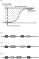
- the ammonia storage capacity or capacity referred to in the context of this invention is given as the quotient of stored mass of ammonia per liter of catalyst volume. It is determined experimentally in a flow tube reactor. To avoid undesirable ammonia oxidation on the reactor material, a reactor made of quartz glass is used. A core sample is taken as a test specimen from the area of the catalyst whose ammonia storage capacity is to be determined. A core sample with a diameter of 1 inch and a length of 3 inches is preferably taken as a test specimen.
- the core sample is inserted into the flow tube reactor and conditioned at a temperature of 600 °C in a gas atmosphere of 500 ppm nitrogen monoxide, 5 vol.% oxygen, 5 vol.% water and the rest nitrogen with a space velocity of 30,000 h -1 for 10 minutes.
- the measuring temperature of 200 °C is then reached in a gas mixture of 0 vol.% oxygen, 5 vol.% water and the rest of nitrogen at a space velocity of 30,000 h -1 .
- the NH 3 storage phase is initiated by switching on a gas mixture of 450 ppm ammonia, 0 vol.% oxygen, 5 vol.% water and the rest of nitrogen at a space velocity of 30,000 h -1 .
- This gas mixture remains switched on until a stationary ammonia breakthrough concentration is recorded on the downstream side of the test specimen.
- the NH 3 concentration measured after the catalyst at stationary conditions can also be lower than the dosed NH 3 concentration.
- the mass of ammonia stored on the test specimen is calculated from the recorded ammonia breakthrough curve by integration from the start of the NH 3 storage phase until the stationarity is reached, taking into account the measured stationary NH 3 breakthrough concentration and the known volume flow (hatched area in the Fig. 1 ).
- the ammonia storage capacity is calculated as the quotient of the stored mass of ammonia divided by the volume of the tested core.
- the additional material for storing ammonia should increase the ammonia storage capacity of the exhaust gas purification system to at least 0.25 g ammonia per liter of substrate volume.
- the storage capacity of the ammonia storage components used should be sufficient to allow the system to store 0.25 to 3.5 g NH 3 per liter of substrate volume, preferably between 0.5 and 2.2 g NH 3 per liter of substrate volume and particularly preferably between 0.5 and 2.0 g NH 3 /liter of substrate volume of ammonia.
- the material for the temporary storage of ammonia can also be able to comparator the nitrogen oxides present in the exhaust gas and the stored ammonia to form nitrogen.
- the ammonia storage acts like a catalyst for selective catalytic reduction (SCR; WO2008106518A2 ).
- SCR selective catalytic reduction
- this SCR catalyst is also equipped with a function for the oxidation of ammonia to nitrogen ( WO2008106519A1 ). It is therefore advantageous that the materials for the temporary storage of ammonia also contain catalysts for the oxidation of NH 3 to N 2.
- this is an ammonia oxidation catalyst (AMOX) or an ammonia blocking catalyst ( US5120695 ; EP1892395A1 ; EP1882832A2 ; EP1876331A2 ; WO12135871A1 ; US2011271664AA ; WO11110919 A1 ). If there are not enough nitrogen oxides in the system to oxidize the stored ammonia, the ammonia can also be converted to nitrogen using the available oxygen via the AMOX. In both cases - as an SCR catalyst or AMOX - no ammonia is released into the environment.
- AMOX ammonia oxidation catalyst
- AMOX ammonia blocking catalyst
- the exhaust gas purification system according to the invention has a function for temporarily storing nitrogen oxides. This prevents excessive amounts of unreacted nitrogen oxides from being emitted during the so-called cold running phases of the vehicle. These are then stored and later, when there is sufficient temperature and reducing agent in the exhaust system, either by reductive regeneration (so-called NOx storage catalysts; NSC) or by thermal desorption (passive NOx storage; PNA) and reduction via a three-way catalyst.
- NSC reductive regeneration
- PNA passive NOx storage
- the present invention also relates to a method for cleaning exhaust gases from a predominantly stoichiometrically operated internal combustion engine, in which the exhaust gas is passed through an exhaust gas cleaning system according to one of the preceding claims.
- the preferred and alternative embodiments named for the system also apply mutatis mutandis to the method.
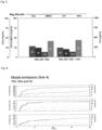
- a Euro 6 petrol vehicle with a 1.5L DI engine was fitted with an artificially aged exhaust system to end-of-life consisting of a first close-coupled TWC with 1.26L catalyst volume (substrate dimensions 118.4mmx114.3mm) and a conventional three-way coating with 1.77 g/L precious metal (0/92/8 Pt/Pd/Rh), an uncoated GPF arranged downstream with 1.39L catalyst volume (substrate dimensions 132.1mmx101.6mm) and a second TWC arranged in the underbody with 1.26L catalyst volume (substrate dimensions 118.4mmx114.3mm) and a conventional three-way coating with 0.83 g/L precious metal (0/80/20 Pt/Pd/Rh) and on a Roller test bench in an RTS aggressive driving cycle.
- This system is called the TWC-GPF-TWC reference system and has a total substrate volume of 3.9L.
- the emissions THC, NMHC, CO, NOx, NH3 and N2O were measured; the measuring technology used for this is known to the expert. The average value from several measurements is shown in each case.
- TWC-GPF-TWC+KAT This system is referred to as TWC-GPF-TWC+KAT and has a total substrate volume of 3.9L.
- the emissions THC, NMHC, CO, NOx, NH 3 and N 2 O were measured; the measuring technology used is known to the expert. The average value from several measurements is shown in each case.
- Figure 5 shows the advantages of the TWC-GPF-TWC+KAT system compared to the TWC_GPF_TWC reference system in a reduction of THC and NMHC emissions by 15% without negatively affecting CO or NOx emissions.
- the benefits for HC emissions are even more evident in Figure 6 , where the averaged cumulative modal curves of HC, CO and NOx are shown during the first 200s of the driving cycle.
- the HC emissions can be reduced by more than a third by the TWC-GPF-TWC+KAT system in blue compared to the TWC-GPF-TWC reference system in black, with no negative impact on the CO or NOx performance. This effect is achieved with the same total substrate volume of the two systems compared, i.e.
Landscapes
- Engineering & Computer Science (AREA)
- Chemical & Material Sciences (AREA)
- Combustion & Propulsion (AREA)
- Mechanical Engineering (AREA)
- General Engineering & Computer Science (AREA)
- Chemical Kinetics & Catalysis (AREA)
- Materials Engineering (AREA)
- Health & Medical Sciences (AREA)
- Toxicology (AREA)
- Catalysts (AREA)
Description
- Die vorliegende Erfindung richtet sich auf die Reinigung von Abgasen eines überwiegend mit stöchiometrischem Kraftstoffgemisch betriebenen Verbrennungsmotors. Das Abgassystem weist insbesondere 4 Reinigungsfunktionen in einer bestimmten Reihenfolge auf. Ein motornaher TWC1 (Drei-Wege-Katalysator) wird gefolgt von einem GPF (Benzinpartikelfilter) und einem dahinter angeordneten weiteren TWC2. Das System weist zusätzlich eine Kohlenwasserstoffe speichernde Funktionalität auf.
- Abgase von mit überwiegend (>50% der Betriebszeit) stöchiometrischem Luft/KraftstoffGemisch betriebenen Verbrennungsmotoren, also z. B. mit Benzin oder Erdgas betriebene Ottomotoren, werden in herkömmlichen Verfahren mit Hilfe von Drei-Wege-Katalysatoren (three-way-catalyst; TWC) gereinigt. Diese sind in der Lage, die drei wesentlichen gasförmigen Schadstoffe des Motors, nämlich Kohlenwasserstoffe, Kohlenmonoxid und Stickoxide, gleichzeitig zu unschädlichen Komponenten umzusetzen. Stöchiometrisch heißt, dass im Mittel genau so viel Luft zur Verbrennung des im Zylinder vorhandenen Kraftstoffs zur Verfügung steht, wie für eine vollständige Verbrennung benötigt wird. Das Verbrennungsluftverhältnis λ (A/F-Verhältnis; Luft/Kraftstoffverhältnis) setzt die tatsächlich für eine Verbrennung zur Verfügung stehende Luftmasse mL,tats ins Verhältnis zur stöchiometrischen Luftmasse mL,st:

- Ist λ < 1 (z. B. 0,9) bedeutet dies "Luftmangel", man spricht von einem fetten Abgasgemisch, λ > 1 (z. B. 1,1) bedeutet "Luftüberschuss" und das Abgasgemisch wird als mager bezeichnet. Die Aussage λ = 1,1 bedeutet, dass 10% mehr Luft vorhanden ist, als zur stöchiometrischen Reaktion notwendig wäre.
- Als katalytisch aktive Materialien werden in den Drei-Wege-Katalysatoren in der Regel Platingruppenmetalle, insbesondere Platin, Palladium und Rhodium eingesetzt, die beispielsweise auf γ-Aluminiumoxid als Trägermaterial vorliegen. Daneben enthalten Dreiwege-Katalysatoren Sauerstoffspeichermaterialien, beispielsweise Cer/Zirkonium-Mischoxide. In letzteren stellt Ceroxid, ein Seltenerdmetalloxid, die für die Sauerstoffspeicherung grundlegende Komponente dar. Neben Zirkoniumoxid und Ceroxid können diese Materialien zusätzliche Bestandteile wie weitere Seltenerdmetalloxide oder Erdalkalimetalloxide enthalten. Sauerstoffspeichermaterialien werden durch Aufbringen von katalytisch aktiven Materialien wie Platingruppenmetallen aktiviert und dienen somit auch als Trägermaterial für die Platingruppenmetalle.
- Derartige katalytisch aktive Materialien samt Inhaltsstoffen werden durch einen Beschichtungsprozess auf z.B. Durchflusssubstrate aufgebracht. Nach dem Trocknen und Kalzinieren der Substrate können diese in das Abgassystem eingebaut werden. Durchflusssubstrate sind aus keramischen Materialien, wie z.B. Siliciumcarbid, Aluminiumtitanat und Cordierit aufgebaut und seit längerem bewährt. Sie sind aus einer Vielzahl von parallelen Kanälen aufgebaut, die durch poröse Wände gebildet werden. Die Kanäle sind an beiden Enden des Durchflusssubstrats offen. Das Abgas fließt so vom Einlassbereich zum Auslassbereich und kontaktiert dabei das auf den Wänden aufgebrachte katalytisch aktive Material.
- Neben den gasförmigen Schadstoffen enthält das Abgas von derartigen Verbrennungsmotoren aber auch feinste Partikel (PM), die aus der unvollständigen Verbrennung des Kraftstoffs resultieren und im Wesentlichen aus Ruß bestehen. Im Unterschied zur Partikelemission von Dieselmotoren sind die Partikel im Abgas stöchiometrisch betriebener Verbrennungsmotoren, wie Ottomotoren, sehr klein und weisen eine durchschnittliche Partikelgröße kleiner 1 µm auf. Typische Partikelgrößen liegen im Bereich von 10 nm bis 200 nm. Des Weiteren ist die emittierte Partikelmenge sehr gering und bewegt sich im Bereich von 2 mg/km bis 4 mg/km.
- Im Bereich der Reinigung von Abgas von mager betriebenen Motoren, also insbesondere von Dieselmotoren, haben sich Partikelfilter aus keramischen Materialien, wie z.B. Siliciumcarbid, Aluminiumtitanat und Cordierit seit längerem bewährt. Diese sind aus einer Vielzahl von parallelen Kanälen aufgebaut, die durch poröse Wände gebildet werden. Die Kanäle sind wechselseitig an einem der beiden Enden des Filters verschlossen, so dass Kanäle A gebildet werden, die an der ersten Seite des Filters offen und auf der zweiten Seite des Filters verschlossen sind, sowie Kanäle B, die an der ersten Seite des Filters verschlossen und auf der zweiten Seite des Filters offen sind. Das beispielsweise in die Kanäle A einströmende Abgas kann den Filter nur über die Kanäle B wieder verlassen, und muss zu diesem Zweck durch die porösen Wände zwischen den Kanälen A und B durchfließen. Beim Durchtritt des Abgases durch die Wand werden die Partikel zurückgehalten und das Abgas gereinigt. Bei derartigen Aggregaten spricht man von Wandflussfiltern.
- Die so zurückgehaltenen Partikel müssen nachfolgend abgebrannt bzw. oxidiert werden, um ein Verstopfen des Filters bzw. einen inakzeptablen Anstieg des Gegendrucks des Abgassystems zu verhindern. Zu diesem Zweck kann beispielsweise das Wandflussfilter mit katalytisch aktiven Beschichtungen versehen werden, die die Zündtemperatur von Ruß herabsetzen. Es ist bereits bekannt, solche Beschichtungen auf die porösen Wände zwischen den Kanälen aufzubringen (sogenannte auf-Wand-Beschichtung) oder in die porösen Wände einzubringen (sogenannte in-Wand-Beschichtung). Die
EP1657410A2 beschreibt auch bereits eine Kombination beider Beschichtungsarten, d. h. ein Teil des katalytisch aktiven Materials liegt in den porösen Wänden und ein anderer Teil auf den porösen Wänden vor. - Das Konzept, Partikel mittels Wandflussfiltern aus dem Abgas zu entfernen, ist bereits auf die Reinigung von Abgas von mit stöchiometrischem Luft/Kraftstoff-Gemisch betriebenen Verbrennungsmotoren übertragen worden, siehe zum Beispiel die
EP2042226A2 (gasoline particle filter; GPF). Gemäß deren Lehre trägt ein Wandflussfilter zwei übereinander angeordnete Schichten, wobei eine in der porösen Wand und die andere auf der porösen Wand angeordnet sein kann. - Die europäische Abgasgesetzgebung sieht seit Inkrafttreten der Stufe Euro 6c ab September 2017 Abgasmessungen unter realen Bedingungen auf der Straße vor (Real Driving Emissions; RDE). Je nach Fahrbedingungen können dadurch deutlich höhere Anforderungen an den Katalysator entstehen, insbesondere im Hinblick auf die dynamische Umsetzung von Kohlenmonoxid und Stickoxiden. In den momentan gültigen Abgasnormen müssen für die Schadstoffe wie HC, CO, NOx und Partikel die Grenzwerte der Euro 6d-Norm unter RDE-Bedingungen auch für alle Neufahrzeuge eingehalten werden. Hinzu kommt, dass ein gewisser CO2-Flottengrenzwert nicht überschritten werden sollte. Insbesondere auch im Hinblick auf die Sekundäremissionen wie N2O und NH3 werden zukünftige Abgasnormen in Europa und der Welt sicherlich noch anspruchsvollere Anforderungen an die Verbrennungsmotoren und deren Abgasaufbereitung stellen.
- Es ist davon auszugehen, dass für derartige Normen einfache Katalysatoren und/oder Filter nicht mehr ausreichend sein werden. Daher werden auch im Bereich der überwiegend stöchiometrisch betriebenen Verbrennungsmotoren komplexere Abgassysteme Einzug halten müssen. Exemplarisch sei auf die
EP3639919A1 verwiesen, in der ein Abgassystem bestehend aus einem ersten TWC gefolgt von einem GPF und einem weiteren TWC abstromseitig vom GPF vorgeschlagen wurde. Mittels dieser Systeme muss es dann gewährleistet werden, eine ausreichende katalytische Aktivität und Filtrationseffizienz mit einem möglichst geringen Abgasgegendruck zu kombinieren. Insbesondere der Abgasgegendruck eines entsprechenden Systems führt zu einem erhöhten Verbrauch an Kraftstoff, was sich negativ auf die CO2-Bilanz auswirkt. Darüber hinaus kommen in zukünftigen Abgasnormen auch mehr und mehr sekundäre Emissionen wie das giftige NH3 oder klimaschädliches N2O in den Blick. Alle diese Aspekte sollte ein entsprechendes zukünftiges Abgassystem adressieren können. Weitere Abgasreinigungssysteme werden in den folgenden Publikationen beschrieben:
EP 3 642 460 B1 ,DE 10 2019 219115 A1 ,US 2018/230882 A1 ,DE 10 2013 211387 A1 ,US 10 323 593 B2 US 6 729 129 B2 . - Es besteht daher weiterhin ein Bedarf an Abgasreinigungssystemen für überwiegend mit stöchiometrischen Kraftstoffgemischen betriebenen Verbrennungsmotoren, die im Stande sind, alle erforderlichen schädlichen Bestandteile des Abgases dieser Motoren in höchst möglicher Weise zu beseitigen und dabei einen möglichst geringen Mehrverbrauch an Kraftstoff bedingen.
- Diese und weitere sich aus dem Stand der Technik für den Fachmann ergebenden Aufgaben werden von einem Abgassystem gemäß vorliegender Erfindung gelöst. Dadurch, dass man in einem Abgasreinigungssystem zur Reinigung von Abgasen eines überwiegend stöchiometrisch betriebenen Verbrennungsmotors aufweisend einen motornahen TWC1 auf einem Durchflusssubstrat, einen abstromseitig zum TWC1 angebrachten GPF als Wandflussfilter und abstromseitig zum GPF einen weiteren TWC2 auf einem Durchflusssubstrat, das System dahingehend modifiziert, dass es zusätzlich Materialien zum temporären Speichern von Kohlenwasserstoffen aufweist, gelangt man äußerst überraschend und vorteilhaft zur Lösung der gestellten Aufgaben.
- Unter dem Begriff "temporär" wird erfindungsgemäß verstanden, dass das Material in bestimmten Betriebszuständen des Abgassystems Kohlenwasserstoffe einspeichern kann und unter anderen diesen wieder abgibt bzw. keinen mehr aufnimmt. Das Speichermaterial selbst wird hierdurch nicht verändert. So kann das Material z.B. bei niedrigen Temperaturen die im Abgas befindlichen Kohlenwasserstoffe einspeichern und bei erhöhten Temperaturen wieder abgeben bzw. umsetzen (siehe hierzu weiter unten). Damit steht das Speichermaterial dann für eine weitere Einspeicherung von Kohlenwasserstoffen wieder zur Verfügung.
- Die Etablierung eines Materials zum Speichern von Kohlenwasserstoffen in dem oben dargestellten System stellt eine optimale Kombination von vier funktionalen Abgasreinigungskomponenten dar, die zukünftige Abgasgrenzwerte einzuhalten erlaubt und darüber hinaus die Möglichkeit eröffnet, ein hohes Maß an Schadstoffreduktion im System zu realisieren. Durch die zusätzliche Speicherfunktion können im Abgas nicht umgesetzte Kohlenwasserstoffe insbesondere bei niedrigen Temperaturen abgefangen und eingespeichert werden. Sie gelangen so nicht in die Umwelt. Sofern es die Betriebszustände des Abgasreinigungssystems zulassen, werden die Kohlenwasserstoffe insbesondere bei höheren Abgastemperaturen wieder desorbiert und z.B. über einem TWC zu Wasser und Kohlendioxid oxidiert.
- Materialien zum Speichern von Kohlenwasserstoffen werden auch Kohlenwasserstofffallen (hydrocarbon trap; HCT) genannt. Die bevorzugt eingesetzten HCTs nehmen aus dem Abgas die emittierten Kohlenwasserstoffe bei niedrigen Temperaturen von weniger als 300°C, vorzugsweise weniger als 350°C auf (es wird bei dieser Temperatur netto mehr gespeichert als abgegeben). Die HCT kann mit einem Oxidationskatalysator vergesellschaftet sein. Die Kohlenwasserstoffspeicherfähigkeit wird bevorzugt im Frischzustand bestimmt. Die Speicherfähigkeit der eingesetzten Materialien für Kohlenwasserstoffe kann nach Maßgabe der in der genannten Literatur beschriebenen Vorgehensweise bestimmt werden. Die im Rahmen dieser Erfindung angesprochene Kohlenwasserstoffspeicherfähigkeit bzw. -kapazität wird als Quotient aus gespeicherter Masse an Kohlenwasserstoffen pro Liter Substratvolumen angegeben. Tests zur Bestimmung der Kohlenwasserstoffspeicherfähigkeit sind dem Fachmann hinlänglich bekannt und in der Literatur beschrieben, beispielsweise in Lupescu et al., "A New Catalyzed HC Trap Technology that Enhances the Conversion of Gasoline Fuel Cold-Start Emissions," SAE Int. J. Fuels Lubr 11(4): 411-425, 2018.
- Durch das zusätzliche Material zur temporären Speicherung von Kohlenwasserstoffen sollte die Kohlenwasserstoffspeicherfähigkeit des Abgasreinigungssystems auf mindestens 0,02 g Kohlenwasserstoffe pro L Substratvolumen erhöht werden (gemessen im Frischzustand). Insgesamt sollte die Speicherkapazität der eingesetzten Kohlenwasserstoffspeicherkomponenten ausreichen, damit im System zwischen 0,02 und 7,0 g Kohlenwasserstoffe pro Liter Substratvolumen, bevorzugt zwischen 0,05 und 6,0 g Kohlenwasserstoffe pro Liter Substratvolumen und besonders bevorzugt zwischen 0,08 und 5,0 g Kohlenwasserstoffe pro Liter Substratvolumen gespeichert werden kann (immer bezogen auf den Frischzustand und das Substrat auf dem die Materialien sich befinden). Diese, die Kohlenwasserstoffe temporär speichernden Materialen sind in einer ausreichenden Menge im Abgassystem vorhanden. Als bevorzugte Menge hat sich ein Wert von 50 - 350 g/L, vorzugsweise 75 - 300 g/L und ganz bevorzugt 100 - 250 g/L Substratvolumen erwiesen. Als Substratvolumen wird das Volumen des Substrats herangezogen, auf dem sich das Speichermaterial befindet.
- Für die temporäre Speicherung von Kohlenwasserstoffen können dem Fachmann geläufige Materialien herangezogen werden. Vorzugsweise sind dies Zeolithe, wie z.B. Mordenite (MOR), Y-Zeolithe (FAU), ZSM-5 (MFI), Ferrierite (FER), Chabazite (CHA), AEI, LEV und β-Zeolithe (BEA) sowie zeolithähnlichen Materialien, wie z.B. Aluminiumphosphate (AIPO) und Siliziumaluminiumphosphat (SAPO) oder Mischungen davon (
EP0324082A1 ). Materialien, welche sich für die Anwendung zur Speicherung von NH3 als besonders günstig erwiesen haben, sind in derUS2006/0010857AA bzw.WO2004076829A1 benannt. Besonders bevorzugt werden ZSM-5 (MFI), Chabazite (CHA), Ferrierite (FER), SAPO-34 und β-Zeolithe (BEA) eingesetzt. Ganz besonders bevorzugt werden CHA , BEA und AIPO-34 bzw. SAPO-34 verwendet. Äußerst bevorzugt werden Materialien des BEA-Typs verwendet. Diese Materialien sind, um eine verbesserte Speicheraktivität zu gewährleisten, vorzugsweise mit einem oder mehreren Metallen aus der Gruppe bestehend aus Eisen, Kupfer, Cäsium, Cer, Lanthan, Nickel, Mangan, Silber und Palladium versehen. Ganz besonders vorteilhaft ist Eisen in diesem Zusammenhang zu nennen. Der Fachmann weiß dabei, wie er die Zeolithe oder das zeolithähnliche Material mit den Übergangsmetallen zu versehen hat (PCT/EP2012/061382 - Unter dem Begriff "Zeolith" versteht man poröse Materialien mit einer Gitterstruktur aus eckenverknüpften AlO4 und SiO4-Tetraedern gemäß der allgemeinen Formel (W.M. Meier, Pure & Appl. Chem., Vol. 58, No. 10, pp. 1323-1328, 1986):
Mm/z [m AlO2 * n SiO2] * q H2O
- Die Struktur eines Zeolithen umfasst somit ein aus Tetraedern aufgebautes Netzwerk, das Kanäle und Hohlräume umschließt. Man unterscheidet natürlich vorkommende und synthetisch hergestellte Zeolithe.
- Unter dem Begriff "zeolithähnliche Verbindung" wird im Rahmen dieser Schrift eine Verbindung verstanden, die denselben Strukturtyp aufweist, wie eine natürlich vorkommende oder eine synthetisch hergestellte Zeolithverbindung, die sich von solchen jedoch dadurch unterscheidet, dass die entsprechende Käfigstruktur nicht ausschließlich aus Aluminium- und Siliziumgerüstatomen aufgebaut ist. In solchen Verbindungen werden die Aluminium- und/oder Siliziumgerüstatome anteilig durch andere drei-, vier- oder fünfwertige Gerüstatome wie beispielsweise B(III), Ga(III), Ge(IV), Ti(IV) oder P(V) ersetzt. In der Praxis am häufigsten zur Anwendung kommt der Ersatz von Aluminium- und/oder Siliziumgerüstatomen durch Phosphoratome, beispielsweise in den Siliziumaluminiumphosphaten oder in den Aluminiumphosphaten, die in Zeolithstrukturtypen kristallisieren. Prominente Beispiele sind das in Chabazitstruktur kristallisierende Siliziumaluminiumphosphat SAPO-34 und das in Chabazitstruktur kristallisierende Aluminiumphosphat AIPO-34.
- Der besondere Vorteil des erfindungsgemäßen Einsatzes von übergangsmetallausgetauschten Zeolithen bzw. zeolithähnlichen Verbindungen ist die Möglichkeit, dass diese Substanzen wie oben schon gesagt bei niedrigeren Temperaturen, z.B. im sogenannten Kaltstartmodus die unverbrannten Kohlenwasserstoffe einspeichern und diese dann erst bei erhöhten Temperaturen wieder abgeben. Bei diesen Temperaturen sind Katalysatoren zum Oxidieren von Kohlenwasserstoffen dann soweit aufgeheizt, dass diese die desorbierten Kohlenwasserstoffe entsprechend zu Wasser und Kohlendioxid oxidieren können. Insbesondere beim Einsatz der Kohlenwasserstoffe temporär speichernden Materialien auf einem separaten Durchflusssubstrat ist es von Vorteil, wenn diese Materialien ebenfalls Katalysatoren zur Oxidation von Kohlenwasserstoffen zu H2O und CO2 aufweisen. Es wird auf das weiter unten zu diesem Punkt Gesagte verwiesen.
- Das, die Kohlenwasserstoffe temporär speichernde Material kann im Abgasreinigungssystem auf einem oder den schon vorhandenen Aggregaten verteilt werden. Hierbei kann das entsprechende Material im Verhältnis zu den ggf. schon vorhandenen katalytisch aktiven Materialien vergesellschaftet mit diesen oder in Zonen oder Schichten getrennt zu diesen auf einem oder mehreren Substraten vorliegen. Als solches bietet es sich an, das die Kohlenwasserstoffe temporär speichernde Material überwiegend auf den TWC2 zu verorten. Sofern in bestimmten Betriebszuständen Kohlenwasserstoffe vermehrt nach dem TWC1 vorhanden sein sollten, so können diese auf dem abstromseitig positionierten TWC2 entsprechend eingespeichert bzw. umgewandelt werden. Da der TWC2 vom Motorauslass entsprechend weiter entfernt ist, ist die Temperaturbelastung hier moderater, was einer besseren Speicherung Vorschub leistet. Sofern der vorzugsweise im Unterboden befindliche TWC2 dann auf Betriebstemperatur aufgewärmt ist, werden die eingespeicherten Kohlenwasserstoffe desorbiert und über dem TWC2 zu CO2 und Wasser umgesetzt. So wird auch eine thermische Schädigung des die Kohlenwasserstoffe temporär speichernden Materials maximal vermieden.
- Alternativ aber bevorzugt kann das die Kohlenwasserstoffe temporär speichernde Material jedoch auch auf einem separaten Durchflusssubstrat angeordnet sein. Hierbei kann dieses Durchflusssubstrat (KAT) nach dem Fachmann bekannten Gesichtspunkten im Abgasreinigungssystem angeordnet werden (siehe
Fig. 2 - 4 ). Bevorzugt ist eine Anordnung, bei der KAT abstromseitig zum TWC2 angeordnet ist. Die Vorteile sind die gleichen wie oben für die Verortung des entsprechenden Materials auf den TWC2 genannten. Damit ist der KAT - wie der TWC2 - vorzugsweise im Unterboden des Fahrzeugs angesiedelt. Erfindungsgemäß ist der KAT abstromseitig zum TWC1 und hinter dem GPF beheimatet. Insbesondere scheint es bei dieser letztgenannten Kombination von Vorteil zu sein, wenn der KAT in einer Entfernung von 30 - 250 cm, vorzugsweise 40 - 200 cm und ganz bevorzugt 50 - 180 cm abstromseitig zum Ausgang des TWC1 angeordnet ist. Ganz besondere bevorzugt wird der KAT im Unterboden des Fahrzeugs beheimatet. - Generell hat es sich als vorteilhaft erwiesen, wenn die einzelnen Substrate des erfindungsgemäßen Abgasreinigungssystems (TWC1, GPF, TWC2, KAT) hinsichtlich der Größe des Volumens, dass sie einnehmen, in einem bestimmten Verhältnis zueinander stehen. So ist von Vorteil, wenn der TWC1 einen Anteil des Volumens am Gesamtsystem einnimmt, welcher zwischen 20 und 50 Vol.-%, bevorzugt 30 - 40 Vol.-% liegt. Der GPF sollte einen Volumenanteil von 20 - 60 Vol.-%, bevorzugt 25 - 55 Vol.-% bezogen auf das Gesamtsystem aufweisen. Gleichfalls sollte der Anteil von TWC2 am Gesamtsystem 10 - 40 Vol.-%, bevorzugt 15 - 35 Vol.-% betragen. Der KAT aufweisend das Material zum temporären Speichern von Stickoxiden besitzt einen Anteil von vorzugsweise 5 - 30 Vol.-%, mehr bevorzugt 10 - 30 Vol.-% an dem Gesamtvolumen der Substrate im Abgasreinigungssystem. Unter Gesamtsystem wird hier die Summe der Volumina der Substrate von TWC1, GPF, TWC2 und KAT verstanden.
- Der KAT weist eine relativ hohe Washcoatbeladung in g/L auf, die von 100 - 500 g/L, bevorzugt 125 - 450 g/L und ganz bevorzugt 150 - 400 g/L reicht. Der Aufbau des KAT entspricht in einer Ausgestaltung dem eines Oxidationskatalysators. Letzterer besitzt eine Oxidationsfunktion, um Kohlenwasserstoffe im Abgas oxidieren zu können. Bei derartigen Katalysatoren hat es sich als vorteilhaft erwiesen, wenn diese in einem zonierten und/oder geschichteten Aufbau vorliegen. Z.B. kann der KAT eine obere auf dem Substrat aufgebrachte Schicht mit einer Oxidationsfunktion für die Oxidation von Kohlenwasserstoffen aufweisen und unter dieser Schicht zumindest teilweise eine weitere Schicht mit dem Kohlenwasserstoffe temporär speichernden Material besitzen. Alternativ kann der KAT eine untere Schicht mit einer Oxidationsfunktion aufweisen, über die in einer oberen Schicht das die Kohlenwasserstoffe temporär speichernde Material aufgebracht ist. In einer weiteren alternativen Ausführungsform können die temporäre Speicherfunktion und die Oxidationsfunktion auch ganz oder teilweise vergesellschaftet in derselben Schicht vorliegen und optional zusätzlich eine weitere Schicht mit einer Oxidationsfunktion besitzen. Eine weitere Möglichkeit besteht darin, die temporäre Kohlenwasserstoffspeicherfunktion und die Oxidationsfunktion auf verschiedene Substrate aufzubringen. Als Ausgestaltungen hinsichtlich des Designs und der Materialien für die HCT kommen insbesondere solche aus der
US20190351397AA ,US20190351398AA oderUS20190351393AA in Frage. - Das die Kohlenwasserstoffe temporär speichernde Material kann dabei wie weiter oben beschrieben ausgebildet sein. Als besonders bevorzugt haben sich hier mit Kupfer oder Eisen und/oder Palladium übergangsmetallausgetauschte Zeolithe des CHA, BEA bzw. AEI erwiesen. Mit Eisen oder Eisen und Palladium ausgetauschtes BEA ist besonders bevorzugt. Die Oxidationsfunktion wird im Wesentlichen durch die Metalle Rh, Pt und/oder Pd, bevorzugt Pt und/oder Pd oder Rh oder Rh und Pd bereitgestellt, die in einer Ausführungsform auf hochoberflächigem aktiven Aluminium geträgert sind. Aktives Aluminium enthält bis zu 10 Gew.-% bezogen auf das Aluminiumoxid an Lanthan und/oder SiO2 als Beimengung. In einer alternativen aber bevorzugten Ausführungsform wird die Oxidationsfunktion durch Rh und/oder Pd und/oder Pt bereitgestellt, die auf ein Gemisch aus hochoberflächigem Aluminiumoxid und gängigen Sauerstoffspeichermaterialien wie Ceroxide, Cer-Zirkonmischoxide oder mit La, Y, Pr, Nd dotierte Cer bzw. Cer-Zirkonmischoxide geträgert sind. Durch das Design des KAT, die Applikation und Auswahl der Edelmetalle lässt sich die oxidative Wirkung der oxidativen Beschichtung gut austarieren, um eine ausreichende oxidative Wirkung auf die Kohlenwasserstoffe ausüben zu können.
- Es kann ebenfalls von Vorteil sein, wenn den Kohlenwasserstoffe temporär speichernden Materialien auf dem KAT auch solche zugefügt werden, die befähigt sind, Sauerstoff zu speichern. Letzteres sind die in den TWCs in der Regel eingesetzten Sauerstoffspeichermaterialien. Diese bewirken die Bereitstellung einer sauerstoffreicheren Umgebung, die für die Oxidation von Kohlenwasserstoffen vorteilhaft ist. Entsprechende Materialien sind u.a. in der
EP2007682A1 ,EP1921044A2 ,US6468941B1 ,US6585944B1 undUS20050282698A1 beschrieben. Vorzugsweise kommen diesbezüglich Ceroxide, Cer-Zirkonmischoxide oder mit La, Y, Pr, Nd dotierte Cer bzw. Cer-Zirkonmischoxide in Betracht. Die Menge an Sauerstoff speicherndem Material kann vom Fachmann bemessen werden, sollte aber nicht unter 0,1 g/g, vorzugsweise 0,20 g/g bezogen auf das Gewicht des die Kohlenwasserstoffe temporär speichernden Materials eingesetzt werden. - TWC1 und TWC2 sind moderne Drei-Wege-Katalysatoren. Der Fachmann weiß, welche er für den vorliegenden Zweck einsetzen würde (siehe z.B.
WO2019121994A1 ,WO2019121995A1 ,WO9535152A1 WO2008000449A2 ,EP0885650A2 ,EP1046423A2 ,EP1726359A1 ,EP1541220A1 ,EP1900416B1 ,EP3045226A1 ,WO2009012348A1 undEP1974809B1 ). Drei-Wege-Katalysatoren bestehen im Wesentlichen aus den Komponenten Edelmetall, hochoberflächiges Trägeroxid und Sauerstoffspeichermaterial. Die Sauerstoffspeichermaterialien sind insbesondere solche, in denen Cer/Zirkonium/Seltenerdmetall-Mischoxiden vorkommen. Als Seltenerdmetalloxid kommen beispielsweise Lanthanoxid, Yttriumoxid, Praseodymoxid, Neodymoxid, Samariumoxid und Mischungen von einem oder mehreren dieser Metalloxide in Betracht. Bevorzugt sind Lanthanoxid, Yttriumoxid, Neodymoxid und Mischungen von einem oder mehreren dieser Metalloxide. Besonders bevorzugt sind Lanthanoxid, Yttriumoxid und ganz besonders bevorzugt ist eine Mischung von Lanthanoxid und Yttriumoxid in diesem Zusammenhang. - Als Trägeroxid für katalytisch aktive Metalle kommen für den Fachmann hochoberflächige, temperaturstabile Oxide in Betracht. In der Regel sind dies Aluminiumoxide, Siliziumoxide, Zirkonoxide oder Titanoxide oder Mischungen derselben. Insbesondere aktives Aluminiumoxid ist dem Fachmann in diesem Zusammenhang bekannt. Es bezeichnet insbesondere γ-Aluminiumoxid mit einer Oberfläche von 100 bis 200 m2/g. Aktives Aluminiumoxid ist in der Literatur vielfach beschrieben und am Markt erhältlich. Es enthält in der Regel Siliziumoxid oder Lanthanoxid als Stabilisator in einer Menge von bis zu 10 Gew.-% bezogen auf das Aluminiumoxid.
- Drei-Wege-Katalysatoren enthalten als katalytisch aktive Komponenten zumeist Metalle der Platingruppe, wie Pt, Pd und Rh, wobei Pd und Rh besonders bevorzugt sind. Die katalytisch aktiven Metalle sind häufig hochdispers auf den hochoberflächigen Oxiden und den Sauerstoffspeichermaterialien abgeschieden. Besonders bevorzugt ist es, wenn die Edelmetalle auf dem Sauerstoffspeichermaterial vorfixiert werden, bevor dieses mit den übrigen Bestandteilen in die Beschichtungsmischung vermengt wird. Bei den TWCs sind gezonte oder gelayerte Ausführungsform mittlerweile der Normalfall. In einer bevorzugten Ausführungsform besitzt zumindest der TWC1 einen 2-Schichtaufbau mit zwei unterschiedlichen Drei-Wege-Beschichtungen, vorzugsweise wie in
EP3247493A1 beschrieben. - Die Drei-Wege-Katalysatoren werden durch einen dem Fachmann geläufigen Beschichtungsschritt vorzugsweise auf ein Durchflusssubstrat aufgebracht. Durchflusssubstrate sind im Stand der Technik übliche Katalysatorträger, die aus Metall (corrugated carrier, z.B.
WO17153239A1 WO16057285A1 WO15121910A1 - Der TWC1 ist erfindungsgemäß vorzugsweise motornah verbaut. Dies bedeutet, dass zwischen dem Turbolader und der einlassseitigen Stirnfläche des TWC1 lediglich 1 - 40 cm Entfernung liegen. Bevorzugt ist der Katalysator TWC1 2 - 30 cm und ganz bevorzugt 3 - 20 cm vom Turbolader entfernt verbaut. Der GPF kann in einigem Abstand vom TWC1, z.B. im Unterboden des Fahrzeugs verbaut werden. Bevorzugt ist jedoch die Ausführungsform, in der GPF recht nahe am auslassseitigen Ende des TWC1 verbaut wird. Bevorzugt ist der Abstand zwischen auslassseitiger Stirnfläche des TWC1 und GPF 1 - 60 cm, mehr bevorzugt 2 - 50 cm und ganz bevorzugt 3 - 40 cm. Der TWC2 ist entweder direkt nach dem Filter in einer motornahen Position verbaut, oder kommt vorzugsweise im Unterboden des Fahrzeugs im Abgassystem zum Einsatz. Dadurch ist die Temperaturbelastung dieses TWCs eine andere als die des TWC1. Aus diesem Grund unterscheiden sind die beiden TWCs in einigen Charakteristika voneinander. Bevorzugt weist der TWC2 eine geringene Washcoatbeladung als der TWC1 auf. Bevorzugt besteht der TWC1 aus mindestens 2-4 verschiedenen Drei-Wege-Katalysatorschichten oder Zonen, während der TWC2 bevorzugt aus mindestens 1-2 Drei-Wege-Katalysatorschichten oder Zonen besteht. In einer weiteren Ausführungsform hat es sich als vorteilhaft erwiesen, wenn die Washcoatbeladung in g/L des TWC1 größer ist als die des TWC2, insbesondere um einen Faktor zwischen 1,25 - 4, mehr bevorzugt 1,5 - 3. Zudem ist die Edelmetallkonzentration auf dem TWC1 bevorzugt größer als auf dem TWC2, insbesondere um einen Faktor 1,25 - 20, mehr bevorzugt 1,5 - 10. Die TWCs weisen eine übliche Washcoatbeladung auf. Diese liegt vorzugsweise bei 100 - 400 g/L, mehr bevorzugt 125 - 375 g/L und ganz bevorzugt 150 - 325 g/L.
- Der GPF hat die Form eines Wandflussfilters. Als Wandflussfilter können alle im Stand der Technik üblichen keramischen Materialien eingesetzt werden. Bevorzugt werden poröse Wandflussfiltersubstrate aus Cordierit, Siliziumcarbid oder Aluminiumtitanat eingesetzt. Diese Wandflussfiltersubstrate weisen An- und Abströmkanäle auf, wobei jeweils die abströmseitigen Enden der Anströmkanäle und die anströmseitigen Enden der Abströmkanäle gegeneinander versetzt mit gasdichten "Stopfen" verschlossen sind. Hierdurch wird das zu reinigende Abgas, das das Filtersubstrat durchströmt, zum Durchtritt durch die poröse Wand zwischen An- und Abströmkanal gezwungen, was eine exzellente Partikelfilterwirkung bedingt. Durch die Porosität, Poren-/Radienverteilung, und Dicke der Wand kann die Filtrationseigenschaft für Partikel ausgelegt werden. Die Porosität der Wandflussfilter beträgt in der Regel mehr als 40%, generell von 40% bis 75%, besonders von 45% to 70% [gemessen nach DIN 66133 - neueste Fassung am Anmeldetag]. Die durchschnittliche Porengröße (Durchmesser) beträgt wenigstens 3 µm, z.B. von 3 µm bis 34 µm, bevorzugt mehr als 5 µm, insbesondere von 5 µm bis 28 µm oder von 7 µm bis 22 µm [gemessen nach DIN 66134 neueste Fassung am Anmeldetag].
- Der GPF kann unbeschichtet, mit einer trockenen Pulverbeschichtung oder mit einer ggf. zusätzlichen, naßtechnisch hergestellten Beschichtung versehen im erfindungsgemäßen System zum Einsatz kommen (
EP3595796A1 ,WO2020200394A1 ,WO2020200397A1 ). Entsprechende naßtechnisch hergestellte Filter mit verbesserter Filterwirkung werden in derWO2019121375A1 bzw.WO2020200398A1 bzw.PCT/EP2019/057995 DE102018108346A1 ,US8277880B2 ). In erste Linie wird durch derartige Beschichtungen die Filtrationseffizienz des Filters verbessert, ohne den Abgasgegendruck des Filters über die Maßen zu verschlechtern. Der GPF kann jedoch auch eine katalytische Beschichtung beherbergen. Ein Katalysatormaterial kann in Form einer Beschichtungssuspension auf und/oder in die porösen Wände der An- und/oder Abströmkanäle aufgetragen werden. In der Regel wird es sich dabei vorliegend um eine Beschichtung mit einem Drei-Wege-Katalysator handeln. Die Zusammensetzung entspricht den oben erfolgten Ausführungen. Somit können alle Aggregate im erfindungsgemäßen Abgasreinigungssystem katalytisch aktive Edelmetalle der oben angegebenen Provenienz aufweisen. In einer vorteilhafte Ausführungsform hat der GPF dabei eine höhere Edelmetallkonzentration in g/L Substratvolumen wie der TWC2. Sofern vorhanden ist es vorteilhaft, wenn der KAT eine höhere Edelmetallkonzentration in g/L Substratvolumen als der TWC2 besitzt. Beide genannten Ausführungsformen können je nach Anwendungsfall jedoch auch reziprok gesehen vorkommen. In einem besonderen Fall kann der TWC2 so ausgebildet sein, dass er lediglich Rhodium als Edelmetall aufweist. - Sofern der GPF mit einer Beschichtung versehen ist, so liegt die Washcoatbeladung bei 10 - 200 g/L, vorzugsweise 20 - 175 g/L und ganz bevorzugt 25 - 150 g/L. Dabei ist es von Vorteil, wenn das Substrat mit den Materialien zum temporären Speichern von Ammoniak (KAT) eine größere Washcoatbeladung in g/L aufweist als der GPF.
- "Electrically heated catalyst" (EHC) sind spezielle Katalysatorkörper, die durch das Anlegen einer Stromquelle erwärmt werden können. Der Vorteil derartiger Systeme liegt darin, dass Betriebszustände des Abgasreinigungssystems vermieden werden, in denen die Katalysatoren aufgrund niedriger Temperaturen nicht oder nicht mehr ausreichend aktiv sind. Solche Betriebszustände existieren im Wesentlichen, wenn das Fahrzeug erst kürzlich gestartet wurde. Durch schnelles elektrisches Aufheizen der Katalysatorsubstrate, können die darauf befindlichen Katalysatoren auf Umsetzungstemperatur gebracht werden und so der Ausstoß unumgesetzter Schadstoffe verringert werden. Vorliegend ist es besonders vorteilhaft, wenn zumindest eines der im System vorhandenen Katalysatorsubstrate (TWC1, GPF, TWC2 oder KAT) ein elektrisch beheizbares Substrat ist. Ganz bevorzugt ist, wenn dies der TWC1 ist. Dieser ist aufgrund seiner Positionierung im System als erstes auf Arbeitstemperatur. Daher ist der Einsatz von Strom hier am geringsten, was gerade im Hinblick auf hybride Anwendung äußerst bevorzugt ist, da die Batterie geschont werden kann. Entsprechende EHC-Systeme in Hybridvehikeln sind dem Fachmann bekannt (
US8776500BB - Um die Schadstoffe, welche vom Fahrzeug emittiert werde, weiter zu reduzieren, kann sich im erfindungsgemäßen Abgasreinigungssystem, vorzugsweise in Strömungsrichtung des Abgases gesehen vor, nach oder im TWC2 ein sogenannter Ammoniakspeicherkatalysator befinden. Dieser kann im System ggf. gebildeten Ammoniak vermindern helfen, bevor er an die Umwelt abgegeben wird. Der Ammoniak wird temporär gespeichert und kann entweder mit vorhandenem Sauerstoff oder vorhandenem Stickoxid oxidiert werden. Hierbei entstehen Stickstoff und Wasser. Für die temporäre Speicherung von Ammoniak können dem Fachmann geläufige Materialien herangezogen werden. Vorzugsweise sind dies Zeolithe, wie z.B. Mordenite (MOR), Y-Zeolithe (FAU), ZSM-5 (MFI), Ferrierite (FER), Chabazite (CHA), AEI, LEV und β-Zeolithe (BEA) sowie zeolithähnlichen Materialien, wie z.B. Aluminiumphosphate (AIPO) und Siliziumaluminiumphosphat (SAPO) oder Mischungen davon (
EP0324082A1 ). Materialien, welche sich für die Anwendung zur Speicherung von NH3 als besonders günstig erwiesen haben, sind in derUS2006/0010857AA bzw.WO2004076829A1 benannt. Besonders bevorzugt werden ZSM-5 (MFI), Chabazite (CHA), Ferrierite (FER), SAPO-34 und β-Zeolithe (BEA) eingesetzt. Ganz besonders bevorzugt werden CHA , BEA und AIPO-34 bzw. SAPO-34 verwendet. Äußerst bevorzugt werden Materialien des CHA-Typs und hier höchst bevorzugt SSZ-13 verwendet. Diese Materialien sind, um eine verbesserte Speicheraktivität zu gewährleisten, vorzugsweise mit Übergangsmetallen aus der Gruppe bestehend aus Eisen, Kupfer, Mangan und Silber versehen. Ganz besonders vorteilhaft ist Kupfer in diesem Zusammenhang zu nennen. Der Fachmann weiß dabei, wie er die Zeolithe oder das zeolithähnliche Material mit den Übergangsmetallen zu versehen hat (PCT/EP2012/061382 - Die Speicherfähigkeit des Substrats für Ammoniak kann nach Maßgabe der folgenden Vorgehensweise bestimmt werden. Die im Rahmen dieser Erfindung angesprochene Ammoniakspeicherfähigkeit bzw. -kapazität wird als Quotient aus gespeicherter Masse Ammoniak pro Liter Katalysatorvolumen angegeben. Sie wird experimentell in einem Strömungsrohrreaktor bestimmt. Zur Vermeidung von unerwünschter Ammoniakoxidation am Reaktormaterial wird ein Reaktor aus Quarzglas verwendet. Aus dem Bereich des Katalysators, dessen Ammoniakspeicherkapazität bestimmt werden soll, wird ein Bohrkern als Prüfling entnommen. Bevorzugt wird ein Bohrkern mit 1 Zoll Durchmesser und 3 Zoll Länge als Prüfling entnommen. Der Bohrkern wird in den Strömungsrohrreaktor eingesetzt und bei einer Temperatur von 600 °C in einer Gasatmosphäre aus 500 ppm Stickstoffmonoxid, 5 Vol.-% Sauerstoff, 5 Vol.-% Wasser und Rest Stickstoff mit einer Raumgeschwindigkeit von 30000 h-1 für 10 Minuten konditioniert. Anschließend wird in einem Gasgemisch aus 0 Vol.-% Sauerstoff, 5 Vol.-% Wasser und Rest Stickstoff mit einer Raumgeschwindigkeit von 30000 h-1 die Messtemperatur von 200 °C angefahren. Nach Stabilisierung der Temperatur wird die NH3-Speicherphase durch Aufschalten eines Gasgemisch aus 450 ppm Ammoniak, 0 Vol.-% Sauerstoff, 5 Vol.-% Wasser und Rest Stickstoff mit einer Raumgeschwindigkeit von 30000 h-1 eingeleitet. Dieses Gasgemisch bleibt so lange aufgeschaltet, bis abströmseitig vom Prüfling eine stationäre Ammoniakdurchbruchskonzentration verzeichnet wird. Die bei Stationarität gemessene NH3-Konzentration nach Katalysator kann auch unter der dosierten NH3-Konzentration liegen. Die auf dem Prüfling eingespeicherte Masse an Ammoniak wird aus der aufgezeichneten Ammoniak-Durchbruchskurve durch Integration vom Start der NH3-Speicher-phase bis zum Erreichen der Stationarität unter Einbeziehung der gemessenen stationären NH3-Durchbruchskonzentration sowie dem bekannten Volumenfluss berechnet (schraffierte Fläche in der
Fig. 1 ). Die Ammoniakspeicherkapazität wird berechnet als Quotient aus der eingespeicherten Masse an Ammoniak, geteilt durch das Volumen des getesteten Bohrkerns. Durch das zusätzliche Material zur Speicherung von Ammoniak sollte die Ammoniakspeicherfähigkeit des Abgasreinigungssystems auf mindestens 0,25 g Ammoniak pro L Substratvolumen erhöht werden. Insgesamt sollte die Speicherkapazität der eingesetzten Ammoniakspeicherkomponenten ausreichen, damit im System 0,25 und 3,5 g NH3 pro Liter Substratvolumen, bevorzugt zwischen 0,5 und 2,2 g NH3 pro Liter Substratvolumen und besonders bevorzugt zwischen 0,5 und 2,0 g NH3/Liter Substratvolumen Ammoniak gespeichert werden kann. - Das Material zur temporären Speicherung von Ammoniak kann zugleich im Stande sein, im Abgas vorhandene Stickoxide und den eingespeicherten Ammoniak zu Stickostoff zu komproportionieren. In diesem Fall wirkt der Ammoniakspeicher wie ein Katalysator zur selektiven katalytischen Reduktion (SCR;
WO2008106518A2 ). Des Weiteren kann es von Vorteil sein, wenn diesem SCR-Katalysator noch eine Funktion zur Oxidation von Ammoniak zu Stickstoff beigefügt wird(WO2008106519A1 ). Vorteilhaft ist daher, dass die Materialien zum temporären Speichern von Ammoniak ebenfalls Katalysatoren zur Oxidation von NH3 zu N2 aufweisen. Als solches handelt es sich dann vorliegend um einen Ammoniakoxidationskatalysator (AMOX) bzw. einen Ammoniaksperrkatalysator (US5120695 ;EP1892395A1 ;EP1882832A2 ;EP1876331A2 ;WO12135871A1 US2011271664AA ;WO11110919 A1 - Ebenfalls von Vorteil ist es, wenn im erfindungsgemäßen Abgasreinigungssystem eine Funktionalität zur temporären Speicherung von Stickoxide vorhanden ist. Hierdurch lässt sich verhindern, dass während sogenannter Kaltlaufphasen des Fahrzeugs übermäßig viele unumgesetzte Stickoxide emittiert werden. Diese werden dann eingespeichert und späterhin, wenn ausreichend Temperatur und Reduktionsmittel im Abgassystem vorhanden ist, entweder durch eine reduktive Regeneration (sogenannte NOx-Speicherkatalysatoren; NSC) oder durch thermale Desorption (passive NOx Speicher; PNA) und Reduktion über einem Drei-Wege-Katalysator vermindert. Bzgl. der Wirkungsweise und den vorzugsweise einzusetzenden Materialien wird auf die einschlägige Literatur verwiesen (
WO2020058265A1 ;EP3695902A1 ;US2019120109AA ;US2018318763AA US2015266002AA ;WO2019134958A1 ). - Ebenfalls Gegenstand der vorliegenden Erfindung bildet ein Verfahren zur Reinigung von Abgasen eines überwiegend stöchiometrisch betriebenen Verbrennungsmotors, bei dem das Abgas über ein Abgasreinigungssystem nach einem der vorhergehenden Ansprüche geleitet wird. Die für das System benannten bevorzugten und alternativen Ausführungsformen gelten mutatis mutandis auch für das Verfahren.
- Mit dem Abgassystem und dem vorgestellten Verfahren gemäß vorliegender Erfindung ist es möglich, die Abgasgrenzwerte zukünftiger noch strengerer Abgasnormen einhalten zu können. Neben den Standardwerten wie HC, CO, NOx und Ruß erlaubt das erfindungsgemäße System zumindest in seinen vorteilhaften Ausgestaltungen auch die Reduzierung sogenannter sekundärer Schadstoffe, wie z.B. NH3, N2O und andere. Im Speziellen die motornahe Anordnung des TWC1 ermöglicht sehr hohe Umsatzraten für die emissionsrelevanten Schadstoffe CO, HC und NOx. Der zusätzliche TWC2 kann ggf. unterstützend wirken und vor allen in Betriebspunkten mit hoher Last und Abgasmassenströmen helfen, die hohen Konversionsraten von CO, HC und NOx sicherzustellen. Die Verwendung des Partikelfilters hingegen, führt zu signifikanten Abscheideraten von Ruß, sodass die gegebenen Emissionsgrenzwerte sicher eingehalten werden können. Dem Fachmann ist hinlänglich bekannt, dass klassische Dreiwegekatalysatoren in den entsprechenden Temperaturregimen und Motorbetriebspunkten gewisse Mengen an Kohlenwasserstoffen nicht vollständig oxidieren können. Schließlich wird durch Verwendung von KAT sichergestellt, dass vor allem im Kaltstart gebildete Kohlenwasserstoffe zusätzlich signifikant reduziert werden können. Damit ist ein solches System prädestiniert dafür in Automobilen eingesetzt zu werden, die zukünftige strenge Abgasgrenzwerte für eine Zulassung einhalten müssen.
-
Fig. 1 : Hier wird die typische Konzentrationskurve einer Ammoniakabsorptionsmessung gezeigt. -
Fig. 2 : Zeigt eine Ausführungsform eines erfindungsgemäßen Systems mit KAT abstromseitig zum TWC2. -
Fig. 3 : Zeigt eine Ausführungsform eines erfindungsgemäßen Systems mit KAT zwischen GPF und TWC2. -
Fig. 4 : Zeigt eine Ausführungsform eines erfindungsgemäßen Systems mit KAT aufstromseitig zum GPF. -
Fig. 5 : Gemittelte Beutelemissionen für THC/NMHC/CO/NOx der beiden Abgasnachbehandlungssysteme TWC-GPF-TWC und TWC-GPF-TWC+KAT im Vergleich. -
Fig. 6 : Gemittelten kumulierten Modalverläufe von HC, CO und NOx während der ersten 200s des Fahrzyklus. - Ein Euro 6 Benzinfahrzeug mit 1,5L DI Motor wurde mit einem künstlich auf End-of-life gealterten Abgassystem bestehend aus einem ersten motornahen TWC mit 1,26L Katalysatorvolumen (Substratdimensionen 118,4mmx114,3mm) und einer konventionellen Dreiwege-Beschichtung mit 1,77 g/L Edelmetall (0/92/8 Pt/Pd/Rh), einem abströmseitig angeordneten, unbeschichteten GPF mit 1,39L Katalysatorvolumen (Substratdimensionen 132,1mmx101,6mm) und einem im Unterboden angeordneten, zweiten TWC mit 1,26L Katalysatorvolumen (Substratdimensionen 118,4mmx114,3mm) und einer konventionellen Dreiwege-Beschichtung mit 0,83 g/L Edelmetall (0/80/20 Pt/Pd/Rh) und auf einem Rollenprüfstand in einem RTS aggressive Fahrzyklus gefahren. Dieses System wird als TWC-GPF-TWC Referenzsystem bezeichnet und hat ein Gesamtsubstratvolumen von 3,9L. Dabei wurden die Emissionen THC, NMHC, CO, NOx, NH3 und N2O gemessen, die dafür zu verwendende Messtechnik ist dem Fachmann bekannt. Dargestellt ist jeweils der Mittelwert aus mehreren Messungen.
- Dem gegenüber gestellt wurde ein System nach den hier genannten Patentansprüchen. Dazu wurde dasselbe Euro 6 Benzinfahrzeug mit 1,5L DI Motor mit einem künstlich auf End-of-life gealterten Abgassystem bestehend aus einem ersten motornahen TWC mit 1,26L Katalysatorvolumen (Substratdimensionen 118,4mmx57,2mm) und einer konventionellen Dreiwege-Beschichtung mit 1,77 g/L Edelmetall (0/92/8 Pt/Pd/Rh), einem abströmseitig angeordneten, unbeschichteten GPF mit 1,39L Katalysatorvolumen (Substratdimensionen 132,1mmx101,6mm), einem im Unterboden angeordneten zweiten TWC mit 0,63L Katalysatorvolumen (Substratdimensionen 118,4mmx57,2mm) und einer konventionellen Dreiwege-Beschichtung mit 0,83 g/L Edelmetall (0/80/20 Pt/Pd/Rh) und einem abströmseitig davon angeordneten KAT mit 0,63L Katalysatorvolumen (Substratdimensionen 118,4mmx57,2mm) und einer Beschichtung, die zusätzlich temporär Kohlenwasserstoffe speichern kann, mit 0,83 g/L Edelmetall (0/80/20 Pt/Pd/Rh) auf einem Rollenprüfstand in einem RTS aggressive Fahrzyklus gefahren. Dieses System wird als TWC-GPF-TWC+KAT bezeichnet und hat ein Gesamtsubstratvolumen von 3,9L. Dabei wurden die Emissionen THC, NMHC, CO, NOx, NH3 und N2O gemessen, die dafür zu verwendende Messtechnik ist dem Fachmann bekannt. Dargestellt ist jeweils der Mittelwert aus mehreren Messungen.
-
Figur 5 zeigt die Vorteile des TWC-GPF-TWC+KAT Systems gegenüber dem TWC_GPF_TWC Referenzsystem in einer Reduktion der THC und NMHC Emissionen um 15%, ohne die CO oder NOx-Emissionen negativ zu beeinflussen. Die Vorteile für die HC-Emissionen werden noch deutlicher inFigur 6 , wo die gemittelten kumulierten Modalverläufe von HC, CO und NOx während der ersten 200s des Fahrzyklus dargestellt sind. Hier können die HC-Emissionen durch das TWC-GPF-TWC+KAT System in blau um mehr als ein Drittel gegenüber dem TWC-GPF-TWC Referenzsystem in schwarz reduziert werden, wobei es keinen negativen Einfluss auf die CO- oder NOx-Performance gibt. Dieser Effekt wird bei gleichem Gesamtsubstratvolumen der beiden verglichenen Systeme erreicht, das heißt bei halbiertem TWC2 des TWC-GPF-TWC+KAT Systems verglichen mit dem des TWC-GPF-TWC Referenzsystems. Bei gleichem Volumen des TWC2 in beiden Systemen ist daher mit einem noch verstärkten Vorteil für das TWC-GPF-TWC+KAT Systems zu rechnen.
Claims (10)
- Abgasreinigungssystem zur Reinigung von Abgasen eines überwiegend stöchiometrisch betriebenen Verbrennungsmotors aufweisend einen motornahen TWC1 auf einem Durchflusssubstrat, einen abstromseitig zum TWC1 angebrachten GPF als Wandflussfilter und abstromseitig zum GPF einen weiteren TWC2 auf einem Durchflusssubstrat,wobeidas System zusätzlich Materialien zum temporären Speichern von Kohlenwasserstoffen aufweist,dadurch gekennzeichnet, dassdiese abstromseitig zum TWC1 und hinter dem GPF beheimatet sind.
- System nach Anspruch 1,
dadurch gekennzeichnet, dass
durch dieses zusätzliche Material die Kohlenwasserstoffspeicherfähigkeit auf mindestens 0,020 g Kohlenwasserstoffe pro L Substratvolumen erhöht wird. - System nach Anspruch 1 und/oder 2,
dadurch gekennzeichnet, dass
die Materialien zum temporären Speichern von Kohlenwasserstoffen in einer Menge von 50 - 350 g/L Substratvolumen im System vorhanden sind. - System nach einem der vorhergehenden Ansprüche,
dadurch gekennzeichnet, dass
die Materialien zum temporären Speichern von Kohlenwasserstoffen Materialien ausgewählt aus der Gruppe bestehend aus Zeolithen oder zeolithähnlichen Materialien aufweisen. - System nach einem der vorhergehenden Ansprüche,
dadurch gekennzeichnet, dass
die Materialien zum temporären Speichern von Kohlenwasserstoffen ebenfalls Katalysatoren zur Oxidation von Kohlenwasserstoffen zu H2O und CO2 aufweisen. - System nach einem der vorhergehenden Ansprüche,
dadurch gekennzeichnet, dass
die Materialien zum temporären Speichern von Kohlenwasserstoffen auf einem separaten Durchflusssubstrat angeordnet sind. - System nach Anspruch 6,
dadurch gekennzeichnet, dass
das Substrat mit den Materialien zum temporären Speichern von Kohlenwasserstoffen einen Anteil von 5 - 30 Vol.-% an dem Gesamtvolumen der Substrate im Abgasreinigungssystem ausmacht. - System nach einem der Ansprüche 6 bis 7,
dadurch gekennzeichnet, dass
das Substrat mit den Materialien zum temporären Speichern von Kohlenwasserstoffen eine größere Washcoatbeladung in g/L aufweist als der GPF. - System nach einem der vorhergehenden Ansprüche,
dadurch gekennzeichnet, dass
mindestens ein Substrat elektrisch beheizbar ist. - Verfahren zur Reinigung von Abgasen eines überwiegend stöchiometrisch betriebenen Verbrennungsmotors, bei dem das Abgas über ein Abgasreinigungssystem nach einem der vorhergehenden Ansprüche geleitet wird.
Applications Claiming Priority (2)
| Application Number | Priority Date | Filing Date | Title |
|---|---|---|---|
| DE102021118803.2A DE102021118803A1 (de) | 2021-07-21 | 2021-07-21 | Abgasreinigungssystem zur Reinigung von Abgasen von Benzinmotoren |
| PCT/EP2022/070289 WO2023001865A1 (de) | 2021-07-21 | 2022-07-20 | Abgasreinigungssystem zur reinigung von abgasen von benzinmotoren |
Publications (2)
| Publication Number | Publication Date |
|---|---|
| EP4374049A1 EP4374049A1 (de) | 2024-05-29 |
| EP4374049B1 true EP4374049B1 (de) | 2025-02-12 |
Family
ID=82846388
Family Applications (1)
| Application Number | Title | Priority Date | Filing Date |
|---|---|---|---|
| EP22751720.8A Active EP4374049B1 (de) | 2021-07-21 | 2022-07-20 | Abgasreinigungssystem zur reinigung von abgasen von benzinmotoren |
Country Status (5)
| Country | Link |
|---|---|
| US (1) | US12410741B2 (de) |
| EP (1) | EP4374049B1 (de) |
| CN (1) | CN117730194A (de) |
| DE (1) | DE102021118803A1 (de) |
| WO (1) | WO2023001865A1 (de) |
Families Citing this family (3)
| Publication number | Priority date | Publication date | Assignee | Title |
|---|---|---|---|---|
| DE102021118802A1 (de) | 2021-07-21 | 2023-01-26 | Umicore Ag & Co. Kg | Abgasreinigungssystem zur Reinigung von Abgasen von Benzinmotoren |
| CN116291835A (zh) * | 2023-05-05 | 2023-06-23 | 中国第一汽车股份有限公司 | 一种汽车排气后处理系统、方法及汽车 |
| WO2025248010A1 (en) * | 2024-05-29 | 2025-12-04 | Basf Mobile Emissions Catalysts Llc | Amox catalyst on gasoline particle filter |
Family Cites Families (95)
| Publication number | Priority date | Publication date | Assignee | Title |
|---|---|---|---|---|
| US4861743A (en) | 1987-11-25 | 1989-08-29 | Uop | Process for the production of molecular sieves |
| US5120695A (en) | 1989-07-28 | 1992-06-09 | Degusaa Aktiengesellschaft (Degussa Ag) | Catalyst for purifying exhaust gases from internal combustion engines and gas turbines operated at above the stoichiometric ratio |
| DE69516281T2 (de) | 1994-06-17 | 2000-08-31 | Engelhard Corp., Iselin | Zusammengesetzter katalysator mit schichtstruktur |
| DE19726322A1 (de) | 1997-06-20 | 1998-12-24 | Degussa | Abgasreinigungskatalysator für Verbrennungsmotoren mit zwei katalytisch aktiven Schichten auf einem Tragkörper |
| EP1046423B8 (de) | 1999-04-23 | 2007-11-21 | Umicore AG & Co. KG | Mehrschichtiger Edelmetall-enthaltender Abgaskatalysator und seine Herstellung |
| JP3664019B2 (ja) * | 1999-12-27 | 2005-06-22 | 日産自動車株式会社 | 触媒コンバータ |
| DE10023439A1 (de) | 2000-05-12 | 2001-11-22 | Dmc2 Degussa Metals Catalysts | Verfahren zur Entfernung von Stickoxiden und Rußpartikeln aus dem mageren Abgas eines Verbrennungsmotors und Abgasreinigungssystem hierfür |
| US6468941B1 (en) | 2000-10-17 | 2002-10-22 | Delphi Technologies, Inc. | Niobium containing zirconium-cerium based soild solutions |
| US6585944B1 (en) | 2000-10-17 | 2003-07-01 | Delphi Technologies, Inc. | Enhancement of the OSC properties of Ce-Zr based solid solutions |
| JP2003201832A (ja) | 2001-10-25 | 2003-07-18 | Nissan Motor Co Ltd | 排ガス浄化触媒システム |
| JP2004176589A (ja) * | 2002-11-26 | 2004-06-24 | Toyota Motor Corp | 排ガス浄化装置 |
| DE10308287B4 (de) | 2003-02-26 | 2006-11-30 | Umicore Ag & Co. Kg | Verfahren zur Abgasreinigung |
| US7875250B2 (en) | 2003-12-11 | 2011-01-25 | Umicore Ag & Co. Kg | Exhaust treatment device, and methods of making the same |
| US20050282698A1 (en) | 2004-06-22 | 2005-12-22 | Southward Barry W | Particulate filter device and exhaust treatment system, and methods of regenerating the same |
| US7213395B2 (en) | 2004-07-14 | 2007-05-08 | Eaton Corporation | Hybrid catalyst system for exhaust emissions reduction |
| JP4907860B2 (ja) | 2004-11-11 | 2012-04-04 | 株式会社キャタラー | フィルタ触媒 |
| JP4648089B2 (ja) | 2005-05-27 | 2011-03-09 | 株式会社キャタラー | 排ガス浄化用触媒 |
| FR2898887B1 (fr) | 2006-03-21 | 2008-05-02 | Rhodia Recherches & Tech | Composition a base d'oxyde de zirconium et d'oxyde de cerium a reductibilite elevee et a surface specifique stable procede de preparation et utilisation dans le traitement des gaz d'echappement |
| KR20090045214A (ko) | 2006-06-29 | 2009-05-07 | 우미코레 아게 운트 코 카게 | 삼원 촉매 |
| DE102006031660A1 (de) | 2006-07-08 | 2008-01-17 | Man Nutzfahrzeuge Ag | Anordnung zur Verminderung von Stickoxiden in Abgasen |
| DE102006031659A1 (de) | 2006-07-08 | 2008-01-10 | Man Nutzfahrzeuge Aktiengesellschaft | Anordnung zur Verminderung von Stickoxiden in Abgasen |
| DE102006038291A1 (de) | 2006-08-16 | 2008-02-21 | Man Nutzfahrzeuge Aktiengesellschaft | Abgasnachbehandlungssystem |
| JP4760625B2 (ja) | 2006-09-06 | 2011-08-31 | マツダ株式会社 | 排ガス浄化用触媒装置 |
| JP5100244B2 (ja) | 2006-10-12 | 2012-12-19 | 第一稀元素化学工業株式会社 | ジルコニア・セリア・イットリア系複合酸化物及びその製造方法 |
| US7601662B2 (en) | 2007-02-27 | 2009-10-13 | Basf Catalysts Llc | Copper CHA zeolite catalysts |
| US7998423B2 (en) | 2007-02-27 | 2011-08-16 | Basf Corporation | SCR on low thermal mass filter substrates |
| EP1974809B1 (de) | 2007-03-19 | 2010-09-29 | Umicore AG & Co. KG | Doppelschichtiger Dreiweg-Katalysator |
| US8007750B2 (en) | 2007-07-19 | 2011-08-30 | Basf Corporation | Multilayered catalyst compositions |
| DE102007046158B4 (de) | 2007-09-27 | 2014-02-13 | Umicore Ag & Co. Kg | Verwendung eines katalytisch aktiven Partikelfilters zur Entfernung von Partikeln aus dem Abgas von mit überwiegend stöchiometrischem Luft/Kraftstoff-Gemisch betriebenen Verbrennungsmotoren |
| JP5061861B2 (ja) | 2007-11-21 | 2012-10-31 | トヨタ自動車株式会社 | 内燃機関の制御装置 |
| US8173087B2 (en) * | 2008-02-05 | 2012-05-08 | Basf Corporation | Gasoline engine emissions treatment systems having particulate traps |
| US8302379B2 (en) | 2008-05-02 | 2012-11-06 | GM Global Technology Operations LLC | Passive ammonia-selective catalytic reduction for NOx control in internal combustion engines |
| US9180408B2 (en) | 2008-05-02 | 2015-11-10 | GM Global Technology Operations LLC | Fuel efficient ammonia generation strategy for lean-burn engines utilizing passive NH3-SCR for the control of NOx |
| US8341947B2 (en) | 2009-09-29 | 2013-01-01 | Ford Global Technologies, Llc | System and method for regenerating a particulate filter |
| US9863348B2 (en) * | 2009-09-29 | 2018-01-09 | Ford Global Technologies, Llc | Method for controlling fuel of a spark ignited engine while regenerating a particulate filter |
| US8926926B2 (en) * | 2009-11-25 | 2015-01-06 | GM Global Technology Operations LLC | Exhaust particulate management for gasoline-fueled engines |
| GB201003784D0 (en) | 2010-03-08 | 2010-04-21 | Johnson Matthey Plc | Improvement in control OPF emissions |
| JP5771267B2 (ja) | 2010-04-20 | 2015-08-26 | ユミコア・アクチエンゲゼルシャフト・ウント・コムパニー・コマンディットゲゼルシャフトUmicore AG & Co.KG | 排気ガス中の窒素酸化物の選択触媒還元のための新規な混合酸化物材料 |
| JP5524696B2 (ja) | 2010-04-22 | 2014-06-18 | 日本碍子株式会社 | 目封止ハニカム構造体の製造方法 |
| US8293182B2 (en) | 2010-05-05 | 2012-10-23 | Basf Corporation | Integrated SCR and AMOx catalyst systems |
| US8722000B2 (en) | 2011-03-29 | 2014-05-13 | Basf Corporation | Multi-component filters for emissions control |
| US20140112849A1 (en) | 2011-06-21 | 2014-04-24 | Umicore Ag & Co., Kg | Method for the depositon of metals on support oxides |
| US8776500B2 (en) | 2012-03-27 | 2014-07-15 | GM Global Technology Operations LLC | System and method for hydrocarbon adsorber regeneration in a hybrid vehicle |
| EP2650042B2 (de) | 2012-04-13 | 2020-09-02 | Umicore AG & Co. KG | Schadstoffminderungssystem für Benzinfahrzeuge |
| GB2503243A (en) | 2012-06-18 | 2013-12-25 | Johnson Matthey Plc | Combined particulate filter and hydrocarbon trap |
| US10323593B2 (en) * | 2013-10-03 | 2019-06-18 | Umicore Ag & Co. Kg | Exhaust aftertreatment system |
| US10072549B2 (en) | 2014-02-12 | 2018-09-11 | Nippon Steel & Sumikin Materials Co., Ltd. | Metal substrate for catalytic converters |
| DE102014204682A1 (de) | 2014-03-13 | 2015-10-01 | Umicore Ag & Co. Kg | Katalysatorsystem zur Reduzierung von Schadgasen aus Benzinverbrennungsmotoren |
| US9687811B2 (en) | 2014-03-21 | 2017-06-27 | SDCmaterials, Inc. | Compositions for passive NOx adsorption (PNA) systems and methods of making and using same |
| JP2016043320A (ja) | 2014-08-25 | 2016-04-04 | エヌ・イーケムキャット株式会社 | 尿素加水分解触媒及び尿素加水分解材料を用いた選択還元触媒 |
| US9908098B2 (en) | 2014-10-06 | 2018-03-06 | Corning Incorporated | Honeycomb filter article and methods thereof |
| US9931596B2 (en) * | 2014-10-21 | 2018-04-03 | Basf Corporation | Emissions treatment systems with TWC catalysts and SCR-HCT catalysts |
| EP3045226B1 (de) | 2015-01-19 | 2024-08-21 | Umicore AG & Co. KG | Doppelschichtiger Dreiweg-Katalysator mit verbesserter Alterungsstabilität |
| EP3268115A4 (de) | 2015-02-11 | 2019-03-06 | SDCmaterials, Inc. | Mager-nox-fallen, einfangmaterialien, washcoats und verfahren zur herstellung und verwendung davon |
| CA2972861C (en) | 2015-03-26 | 2023-03-28 | Basf Corporation | Exhaust gas treatment system |
| JP2018521258A (ja) | 2015-05-19 | 2018-08-02 | ハルドール・トプサー・アクチエゼルスカベット | 粒子状物質および有害化合物をエンジン排気ガスから除去するための方法、多機能フィルタおよびシステム |
| CN108138618B (zh) | 2015-09-24 | 2020-06-16 | 本田技研工业株式会社 | 内燃机的废气净化系统 |
| CN108367241A (zh) | 2015-10-30 | 2018-08-03 | 优美科股份公司及两合公司 | 用于被动nox吸附(pna)体系的组合物及其制备和使用方法 |
| WO2017082563A1 (ko) | 2015-11-10 | 2017-05-18 | 희성촉매 주식회사 | 화학양론적 작동 가솔린 엔진용 배기정화촉매 |
| US9957911B2 (en) | 2016-02-18 | 2018-05-01 | GM Global Technology Operations LLC | Dedicated exhaust gas recirculation control systems and methods |
| WO2017153239A1 (en) | 2016-03-09 | 2017-09-14 | Haldor Topsøe A/S | Preparation method of a non-woven fibrous material-based honeycomb catalyst |
| DE102016112657A1 (de) | 2016-07-11 | 2018-01-11 | Volkswagen Ag | Verfahren und Vorrichtung zur Abgasnachbehandlung eines Verbrennungsmotors |
| JP6827521B2 (ja) | 2016-07-14 | 2021-02-10 | ユミコア・アクチエンゲゼルシャフト・ウント・コムパニー・コマンディットゲゼルシャフトUmicore AG & Co.KG | バナジウムトラップscrシステム |
| US10066576B2 (en) | 2016-07-26 | 2018-09-04 | GM Global Technology Operations LLC | Dual injection during intake stroke for improved catalyst light off |
| KR101855769B1 (ko) | 2016-09-20 | 2018-05-09 | 현대자동차 주식회사 | 배기 시스템 및 질소산화물 탈착 제어 방법 |
| DE112017005130A5 (de) | 2016-10-10 | 2019-08-01 | Umicore Ag & Co. Kg | Katalysatoranordnung |
| US10774720B2 (en) | 2017-02-11 | 2020-09-15 | Tecogen, Inc. | NOx reduction without urea using a dual stage catalyst system with intercooling in vehicle gasoline engines |
| DE102017113366A1 (de) | 2017-06-19 | 2018-12-20 | Volkswagen Aktiengesellschaft | Abgasnachbehandlungssystem sowie Verfahren zur Abgasnachbehandlung eines Verbrennungsmotors |
| DE102017118215A1 (de) * | 2017-08-10 | 2019-02-14 | Volkswagen Ag | Abgasnachbehandlungssystem und Verfahren zur Abgasnachbehandlung eines Verbrennungsmotors |
| JP2020531240A (ja) | 2017-08-31 | 2020-11-05 | ユミコア・アクチエンゲゼルシャフト・ウント・コムパニー・コマンディットゲゼルシャフトUmicore AG & Co.KG | 排気ガスを浄化するためのパラジウム/ゼオライト系受動的窒素酸化物吸着剤触媒 |
| US10711674B2 (en) | 2017-10-20 | 2020-07-14 | Umicore Ag & Co. Kg | Passive nitrogen oxide adsorber catalyst |
| EP3501648B1 (de) | 2017-12-19 | 2023-10-04 | Umicore Ag & Co. Kg | Katalytisch aktives partikelfilter |
| WO2019134958A1 (de) | 2018-01-05 | 2019-07-11 | Umicore Ag & Co. Kg | Passiver stickoxid-adsorber |
| US10156175B1 (en) * | 2018-02-15 | 2018-12-18 | GM Global Technology Operations LLC | Method and system for rationalizing a delta pressure sensor for a gasoline particulate filter in a vehicle propulsion system |
| DE102018108346A1 (de) | 2018-04-09 | 2019-10-10 | Umicore Ag & Co. Kg | Beschichteter Wandflussfilter |
| DE102018111246A1 (de) | 2018-05-09 | 2019-11-14 | Umicore Ag & Co. Kg | Verfahren zum Beschichten eines Wandflussfilters |
| US20190353067A1 (en) | 2018-05-18 | 2019-11-21 | Umicore Ag & Co. Kg | Exhaust treatment systems and methods involving oxygen supplementation and hydrocarbon trapping |
| US10850264B2 (en) | 2018-05-18 | 2020-12-01 | Umicore Ag & Co. Kg | Hydrocarbon trap catalyst |
| US11123720B2 (en) | 2018-05-18 | 2021-09-21 | Umicore Ag & Co. Kg | Hydrocarbon trap catalyst |
| US10828623B2 (en) | 2018-05-18 | 2020-11-10 | Umicore Ag & Co. Kg | Hydrocarbon trap catalyst |
| EP3623047B1 (de) | 2018-09-17 | 2021-02-24 | Umicore Ag & Co. Kg | Katalysator zur reduktion von stickoxiden |
| CN112805457A (zh) | 2018-10-05 | 2021-05-14 | Avl李斯特有限公司 | 具有改进的scr系统的汽油发动机总成和方法 |
| EP3639919B1 (de) | 2018-10-18 | 2025-07-09 | Umicore AG & Co. KG | Abgasreinigungssystem für einen benzinmotor |
| EP3639908B1 (de) | 2018-10-18 | 2024-04-17 | Umicore Ag & Co. Kg | Abgasreinigungssystem für benzinmotoren |
| US11073057B2 (en) | 2019-01-31 | 2021-07-27 | Hyundai Motor Company | Co clean-up catalyst, after treatment system and after treatment method |
| US10914217B2 (en) | 2019-01-31 | 2021-02-09 | Hyundai Motor Company | Ammonia production catalyst and after treatment system |
| EP3695902B1 (de) | 2019-02-18 | 2021-09-01 | Umicore Ag & Co. Kg | Katalysator zur reduktion von stickoxiden |
| US12434231B2 (en) | 2019-03-29 | 2025-10-07 | Umicore Ag & Co. Kg | Catalytically active particulate filter |
| WO2020200398A1 (de) | 2019-03-29 | 2020-10-08 | Umicore Ag & Co. Kg | Katalytisch aktives partikelfilter |
| BR112021017469A2 (pt) * | 2019-03-29 | 2021-11-16 | Johnson Matthey Plc | Sistema de escape, e, método para tratar um gás de escape |
| WO2020200397A1 (de) | 2019-03-29 | 2020-10-08 | Umicore Ag & Co. Kg | Katalytisch aktives partikelfilter |
| DE102019219115A1 (de) | 2019-12-06 | 2021-06-10 | Vitesco Technologies GmbH | Abgassystem zur Abgasnachbehandlung und Verfahren zum Betreiben eines Abgassystems |
| US11608763B2 (en) * | 2021-01-05 | 2023-03-21 | Ford Global Technologies, Llc | Exhaust aftertreatment system |
| DE102021118801A1 (de) | 2021-07-21 | 2023-01-26 | Umicore Ag & Co. Kg | Abgasreinigungssystem zur Reinigung von Abgasen von Benzinmotoren |
| DE102021118802A1 (de) | 2021-07-21 | 2023-01-26 | Umicore Ag & Co. Kg | Abgasreinigungssystem zur Reinigung von Abgasen von Benzinmotoren |
-
2021
- 2021-07-21 DE DE102021118803.2A patent/DE102021118803A1/de active Pending
-
2022
- 2022-07-20 WO PCT/EP2022/070289 patent/WO2023001865A1/de not_active Ceased
- 2022-07-20 CN CN202280050607.3A patent/CN117730194A/zh active Pending
- 2022-07-20 US US18/580,581 patent/US12410741B2/en active Active
- 2022-07-20 EP EP22751720.8A patent/EP4374049B1/de active Active
Also Published As
| Publication number | Publication date |
|---|---|
| WO2023001865A1 (de) | 2023-01-26 |
| EP4374049A1 (de) | 2024-05-29 |
| CN117730194A (zh) | 2024-03-19 |
| US12410741B2 (en) | 2025-09-09 |
| DE102021118803A1 (de) | 2023-01-26 |
| US20240369009A1 (en) | 2024-11-07 |
Similar Documents
| Publication | Publication Date | Title |
|---|---|---|
| EP4374050B1 (de) | Abgasreinigungssystem zur reinigung von abgasen von benzinmotoren | |
| EP1961933B1 (de) | Katalytisch aktiviertes Dieselpartikelfilter mit Ammoniak-Sperrwirkung | |
| EP3103979B1 (de) | Katalysator zur entfernung von stickoxiden aus dem abgas von dieselmotoren | |
| DE10308287B4 (de) | Verfahren zur Abgasreinigung | |
| DE102012218254B4 (de) | Abgassystem für einen verbrennungsmotor | |
| DE102011107692B3 (de) | Verfahren zur Reaktivierung von Abgasreinigungsanlagen von Dieselmotoren mit Niederdruck-AGR | |
| EP3116630B1 (de) | Katalysatorsystem für benzinverbrennungsmotoren mit dreiwegekatalysatoren und scr-katalysator | |
| DE102010014468B4 (de) | Verfahren zur Verminderung von Lachgas bei der Abgasnachbehandlung von Magermotoren | |
| DE102010023819B4 (de) | Abgasbehandlungssystem für einen Dieselmotor Verfahren zu dessen Verwendung und Dieselmotor- und Abgasbehandlungssystem | |
| EP4374049B1 (de) | Abgasreinigungssystem zur reinigung von abgasen von benzinmotoren | |
| DE60123977T2 (de) | Abgassystem für brennkraftmaschinen mit magergemischverbrennung | |
| DE102012222807A1 (de) | Abgassystem für einen mager verbrennenden Verbrennungsmotor, das einen SCR-Katalysator umfasst | |
| DE102014105736A1 (de) | Motor mit Fremdzündung und Abgassystem, das ein katalysiertes in Zonen beschichtetes Filtersubstrat umfasst | |
| DE102012222804A1 (de) | Substratmonolith, der einen SCR-Katalysator umfasst | |
| DE112011103996T5 (de) | Metall-enthaltender Zeolithkatalysator | |
| DE102016118542A1 (de) | Einen russkatalysator und einen scr-katalysator aufweisendes katalytisches filter | |
| EP2498898A1 (de) | Verbesserter dieseloxidationskatalysator | |
| EP2138681A1 (de) | Verfahren und Vorrichtung zur Reinigung von Dieselabgasen | |
| EP3126646B1 (de) | Regenerationsverfahren für abgasnachbehandlungssysteme | |
| EP4373613A1 (de) | Abgasreinigungssystem zur reinigung von abgasen von benzinmotoren | |
| DE102023101768A1 (de) | Abgassystem für überwiegend stöchiometrisch betriebene Verbrennungsmotoren aufweisend einen Katalysator zur Verminderung der Ammoniakemissionen | |
| DE102017100518A1 (de) | System und Verfahren zur Abgasreinigung unter Vermeidung von Lachgas | |
| WO2023198574A1 (de) | Abgassystem für überwiegend stöchiometrisch betriebene verbrennungsmotoren aufweisend einen katalysator zur verminderung der ammoniakemissionen |
Legal Events
| Date | Code | Title | Description |
|---|---|---|---|
| STAA | Information on the status of an ep patent application or granted ep patent |
Free format text: STATUS: UNKNOWN |
|
| STAA | Information on the status of an ep patent application or granted ep patent |
Free format text: STATUS: THE INTERNATIONAL PUBLICATION HAS BEEN MADE |
|
| PUAI | Public reference made under article 153(3) epc to a published international application that has entered the european phase |
Free format text: ORIGINAL CODE: 0009012 |
|
| STAA | Information on the status of an ep patent application or granted ep patent |
Free format text: STATUS: REQUEST FOR EXAMINATION WAS MADE |
|
| 17P | Request for examination filed |
Effective date: 20240221 |
|
| AK | Designated contracting states |
Kind code of ref document: A1 Designated state(s): AL AT BE BG CH CY CZ DE DK EE ES FI FR GB GR HR HU IE IS IT LI LT LU LV MC MK MT NL NO PL PT RO RS SE SI SK SM TR |
|
| DAV | Request for validation of the european patent (deleted) | ||
| DAX | Request for extension of the european patent (deleted) | ||
| GRAP | Despatch of communication of intention to grant a patent |
Free format text: ORIGINAL CODE: EPIDOSNIGR1 |
|
| STAA | Information on the status of an ep patent application or granted ep patent |
Free format text: STATUS: GRANT OF PATENT IS INTENDED |
|
| INTG | Intention to grant announced |
Effective date: 20241203 |
|
| GRAS | Grant fee paid |
Free format text: ORIGINAL CODE: EPIDOSNIGR3 |
|
| GRAA | (expected) grant |
Free format text: ORIGINAL CODE: 0009210 |
|
| STAA | Information on the status of an ep patent application or granted ep patent |
Free format text: STATUS: THE PATENT HAS BEEN GRANTED |
|
| AK | Designated contracting states |
Kind code of ref document: B1 Designated state(s): AL AT BE BG CH CY CZ DE DK EE ES FI FR GB GR HR HU IE IS IT LI LT LU LV MC MK MT NL NO PL PT RO RS SE SI SK SM TR |
|
| REG | Reference to a national code |
Ref country code: GB Ref legal event code: FG4D Free format text: NOT ENGLISH |
|
| REG | Reference to a national code |
Ref country code: CH Ref legal event code: EP |
|
| REG | Reference to a national code |
Ref country code: DE Ref legal event code: R096 Ref document number: 502022002898 Country of ref document: DE |
|
| P01 | Opt-out of the competence of the unified patent court (upc) registered |
Free format text: CASE NUMBER: APP_4538/2025 Effective date: 20250128 |
|
| REG | Reference to a national code |
Ref country code: IE Ref legal event code: FG4D Free format text: LANGUAGE OF EP DOCUMENT: GERMAN |
|
| REG | Reference to a national code |
Ref country code: NL Ref legal event code: MP Effective date: 20250212 |
|
| PG25 | Lapsed in a contracting state [announced via postgrant information from national office to epo] |
Ref country code: RS Free format text: LAPSE BECAUSE OF FAILURE TO SUBMIT A TRANSLATION OF THE DESCRIPTION OR TO PAY THE FEE WITHIN THE PRESCRIBED TIME-LIMIT Effective date: 20250512 |
|
| PG25 | Lapsed in a contracting state [announced via postgrant information from national office to epo] |
Ref country code: FI Free format text: LAPSE BECAUSE OF FAILURE TO SUBMIT A TRANSLATION OF THE DESCRIPTION OR TO PAY THE FEE WITHIN THE PRESCRIBED TIME-LIMIT Effective date: 20250212 |
|
| PG25 | Lapsed in a contracting state [announced via postgrant information from national office to epo] |
Ref country code: PL Free format text: LAPSE BECAUSE OF FAILURE TO SUBMIT A TRANSLATION OF THE DESCRIPTION OR TO PAY THE FEE WITHIN THE PRESCRIBED TIME-LIMIT Effective date: 20250212 |
|
| PG25 | Lapsed in a contracting state [announced via postgrant information from national office to epo] |
Ref country code: ES Free format text: LAPSE BECAUSE OF FAILURE TO SUBMIT A TRANSLATION OF THE DESCRIPTION OR TO PAY THE FEE WITHIN THE PRESCRIBED TIME-LIMIT Effective date: 20250212 |
|
| REG | Reference to a national code |
Ref country code: LT Ref legal event code: MG9D |
|
| PG25 | Lapsed in a contracting state [announced via postgrant information from national office to epo] |
Ref country code: IS Free format text: LAPSE BECAUSE OF FAILURE TO SUBMIT A TRANSLATION OF THE DESCRIPTION OR TO PAY THE FEE WITHIN THE PRESCRIBED TIME-LIMIT Effective date: 20250612 Ref country code: NO Free format text: LAPSE BECAUSE OF FAILURE TO SUBMIT A TRANSLATION OF THE DESCRIPTION OR TO PAY THE FEE WITHIN THE PRESCRIBED TIME-LIMIT Effective date: 20250512 |
|
| PG25 | Lapsed in a contracting state [announced via postgrant information from national office to epo] |
Ref country code: NL Free format text: LAPSE BECAUSE OF FAILURE TO SUBMIT A TRANSLATION OF THE DESCRIPTION OR TO PAY THE FEE WITHIN THE PRESCRIBED TIME-LIMIT Effective date: 20250212 |
|
| PG25 | Lapsed in a contracting state [announced via postgrant information from national office to epo] |
Ref country code: HR Free format text: LAPSE BECAUSE OF FAILURE TO SUBMIT A TRANSLATION OF THE DESCRIPTION OR TO PAY THE FEE WITHIN THE PRESCRIBED TIME-LIMIT Effective date: 20250212 |
|
| PG25 | Lapsed in a contracting state [announced via postgrant information from national office to epo] |
Ref country code: PT Free format text: LAPSE BECAUSE OF FAILURE TO SUBMIT A TRANSLATION OF THE DESCRIPTION OR TO PAY THE FEE WITHIN THE PRESCRIBED TIME-LIMIT Effective date: 20250612 Ref country code: LV Free format text: LAPSE BECAUSE OF FAILURE TO SUBMIT A TRANSLATION OF THE DESCRIPTION OR TO PAY THE FEE WITHIN THE PRESCRIBED TIME-LIMIT Effective date: 20250212 |
|
| PG25 | Lapsed in a contracting state [announced via postgrant information from national office to epo] |
Ref country code: GR Free format text: LAPSE BECAUSE OF FAILURE TO SUBMIT A TRANSLATION OF THE DESCRIPTION OR TO PAY THE FEE WITHIN THE PRESCRIBED TIME-LIMIT Effective date: 20250513 Ref country code: BG Free format text: LAPSE BECAUSE OF FAILURE TO SUBMIT A TRANSLATION OF THE DESCRIPTION OR TO PAY THE FEE WITHIN THE PRESCRIBED TIME-LIMIT Effective date: 20250212 |
|
| PG25 | Lapsed in a contracting state [announced via postgrant information from national office to epo] |
Ref country code: SE Free format text: LAPSE BECAUSE OF FAILURE TO SUBMIT A TRANSLATION OF THE DESCRIPTION OR TO PAY THE FEE WITHIN THE PRESCRIBED TIME-LIMIT Effective date: 20250212 |
|
| PG25 | Lapsed in a contracting state [announced via postgrant information from national office to epo] |
Ref country code: SM Free format text: LAPSE BECAUSE OF FAILURE TO SUBMIT A TRANSLATION OF THE DESCRIPTION OR TO PAY THE FEE WITHIN THE PRESCRIBED TIME-LIMIT Effective date: 20250212 |
|
| PG25 | Lapsed in a contracting state [announced via postgrant information from national office to epo] |
Ref country code: DK Free format text: LAPSE BECAUSE OF FAILURE TO SUBMIT A TRANSLATION OF THE DESCRIPTION OR TO PAY THE FEE WITHIN THE PRESCRIBED TIME-LIMIT Effective date: 20250212 |
|
| PGFP | Annual fee paid to national office [announced via postgrant information from national office to epo] |
Ref country code: DE Payment date: 20250604 Year of fee payment: 4 |
|
| PG25 | Lapsed in a contracting state [announced via postgrant information from national office to epo] |
Ref country code: IT Free format text: LAPSE BECAUSE OF FAILURE TO SUBMIT A TRANSLATION OF THE DESCRIPTION OR TO PAY THE FEE WITHIN THE PRESCRIBED TIME-LIMIT Effective date: 20250212 |
|
| PGFP | Annual fee paid to national office [announced via postgrant information from national office to epo] |
Ref country code: AT Payment date: 20251020 Year of fee payment: 4 |
|
| PG25 | Lapsed in a contracting state [announced via postgrant information from national office to epo] |
Ref country code: EE Free format text: LAPSE BECAUSE OF FAILURE TO SUBMIT A TRANSLATION OF THE DESCRIPTION OR TO PAY THE FEE WITHIN THE PRESCRIBED TIME-LIMIT Effective date: 20250212 Ref country code: CZ Free format text: LAPSE BECAUSE OF FAILURE TO SUBMIT A TRANSLATION OF THE DESCRIPTION OR TO PAY THE FEE WITHIN THE PRESCRIBED TIME-LIMIT Effective date: 20250212 |
|
| PG25 | Lapsed in a contracting state [announced via postgrant information from national office to epo] |
Ref country code: RO Free format text: LAPSE BECAUSE OF FAILURE TO SUBMIT A TRANSLATION OF THE DESCRIPTION OR TO PAY THE FEE WITHIN THE PRESCRIBED TIME-LIMIT Effective date: 20250212 |
|
| PG25 | Lapsed in a contracting state [announced via postgrant information from national office to epo] |
Ref country code: SK Free format text: LAPSE BECAUSE OF FAILURE TO SUBMIT A TRANSLATION OF THE DESCRIPTION OR TO PAY THE FEE WITHIN THE PRESCRIBED TIME-LIMIT Effective date: 20250212 |
|
| REG | Reference to a national code |
Ref country code: DE Ref legal event code: R097 Ref document number: 502022002898 Country of ref document: DE |
|
| PLBE | No opposition filed within time limit |
Free format text: ORIGINAL CODE: 0009261 |
|
| STAA | Information on the status of an ep patent application or granted ep patent |
Free format text: STATUS: NO OPPOSITION FILED WITHIN TIME LIMIT |
|
| 26N | No opposition filed |
Effective date: 20251113 |