EP4328395A2 - Bauwerk mit thermisch isolierendem bauelement - Google Patents
Bauwerk mit thermisch isolierendem bauelement Download PDFInfo
- Publication number
- EP4328395A2 EP4328395A2 EP24151937.0A EP24151937A EP4328395A2 EP 4328395 A2 EP4328395 A2 EP 4328395A2 EP 24151937 A EP24151937 A EP 24151937A EP 4328395 A2 EP4328395 A2 EP 4328395A2
- Authority
- EP
- European Patent Office
- Prior art keywords
- building
- insulating body
- thermally insulating
- force
- structural part
- Prior art date
- Legal status (The legal status is an assumption and is not a legal conclusion. Google has not performed a legal analysis and makes no representation as to the accuracy of the status listed.)
- Pending
Links
- 238000010276 construction Methods 0.000 title 1
- 238000009413 insulation Methods 0.000 claims abstract description 36
- 238000004873 anchoring Methods 0.000 description 13
- 239000011810 insulating material Substances 0.000 description 10
- 239000004567 concrete Substances 0.000 description 8
- 238000009434 installation Methods 0.000 description 8
- 238000012986 modification Methods 0.000 description 7
- 230000004048 modification Effects 0.000 description 7
- 239000007769 metal material Substances 0.000 description 4
- 238000003860 storage Methods 0.000 description 4
- 239000011449 brick Substances 0.000 description 3
- 230000000694 effects Effects 0.000 description 3
- 239000000835 fiber Substances 0.000 description 3
- 230000005540 biological transmission Effects 0.000 description 2
- 239000011372 high-strength concrete Substances 0.000 description 2
- 239000004570 mortar (masonry) Substances 0.000 description 2
- 230000002787 reinforcement Effects 0.000 description 2
- 229920000049 Carbon (fiber) Polymers 0.000 description 1
- 239000004917 carbon fiber Substances 0.000 description 1
- 239000003000 extruded plastic Substances 0.000 description 1
- 238000011065 in-situ storage Methods 0.000 description 1
- 239000000463 material Substances 0.000 description 1
- 239000002184 metal Substances 0.000 description 1
- 239000004033 plastic Substances 0.000 description 1
Images


Classifications
-
- E—FIXED CONSTRUCTIONS
- E04—BUILDING
- E04B—GENERAL BUILDING CONSTRUCTIONS; WALLS, e.g. PARTITIONS; ROOFS; FLOORS; CEILINGS; INSULATION OR OTHER PROTECTION OF BUILDINGS
- E04B1/00—Constructions in general; Structures which are not restricted either to walls, e.g. partitions, or floors or ceilings or roofs
- E04B1/38—Connections for building structures in general
-
- E—FIXED CONSTRUCTIONS
- E04—BUILDING
- E04B—GENERAL BUILDING CONSTRUCTIONS; WALLS, e.g. PARTITIONS; ROOFS; FLOORS; CEILINGS; INSULATION OR OTHER PROTECTION OF BUILDINGS
- E04B1/00—Constructions in general; Structures which are not restricted either to walls, e.g. partitions, or floors or ceilings or roofs
- E04B1/62—Insulation or other protection; Elements or use of specified material therefor
- E04B1/66—Sealings
- E04B1/68—Sealings of joints, e.g. expansion joints
-
- E—FIXED CONSTRUCTIONS
- E04—BUILDING
- E04B—GENERAL BUILDING CONSTRUCTIONS; WALLS, e.g. PARTITIONS; ROOFS; FLOORS; CEILINGS; INSULATION OR OTHER PROTECTION OF BUILDINGS
- E04B1/00—Constructions in general; Structures which are not restricted either to walls, e.g. partitions, or floors or ceilings or roofs
- E04B1/62—Insulation or other protection; Elements or use of specified material therefor
- E04B1/74—Heat, sound or noise insulation, absorption, or reflection; Other building methods affording favourable thermal or acoustical conditions, e.g. accumulating of heat within walls
- E04B1/76—Heat, sound or noise insulation, absorption, or reflection; Other building methods affording favourable thermal or acoustical conditions, e.g. accumulating of heat within walls specifically with respect to heat only
- E04B1/78—Heat insulating elements
-
- E—FIXED CONSTRUCTIONS
- E04—BUILDING
- E04B—GENERAL BUILDING CONSTRUCTIONS; WALLS, e.g. PARTITIONS; ROOFS; FLOORS; CEILINGS; INSULATION OR OTHER PROTECTION OF BUILDINGS
- E04B1/00—Constructions in general; Structures which are not restricted either to walls, e.g. partitions, or floors or ceilings or roofs
- E04B1/003—Balconies; Decks
- E04B1/0038—Anchoring devices specially adapted therefor with means for preventing cold bridging
-
- E—FIXED CONSTRUCTIONS
- E04—BUILDING
- E04B—GENERAL BUILDING CONSTRUCTIONS; WALLS, e.g. PARTITIONS; ROOFS; FLOORS; CEILINGS; INSULATION OR OTHER PROTECTION OF BUILDINGS
- E04B1/00—Constructions in general; Structures which are not restricted either to walls, e.g. partitions, or floors or ceilings or roofs
- E04B1/62—Insulation or other protection; Elements or use of specified material therefor
- E04B1/74—Heat, sound or noise insulation, absorption, or reflection; Other building methods affording favourable thermal or acoustical conditions, e.g. accumulating of heat within walls
- E04B1/76—Heat, sound or noise insulation, absorption, or reflection; Other building methods affording favourable thermal or acoustical conditions, e.g. accumulating of heat within walls specifically with respect to heat only
- E04B2001/7679—Means preventing cold bridging at the junction of an exterior wall with an interior wall or a floor
-
- E—FIXED CONSTRUCTIONS
- E04—BUILDING
- E04C—STRUCTURAL ELEMENTS; BUILDING MATERIALS
- E04C5/00—Reinforcing elements, e.g. for concrete; Auxiliary elements therefor
- E04C5/01—Reinforcing elements of metal, e.g. with non-structural coatings
- E04C5/06—Reinforcing elements of metal, e.g. with non-structural coatings of high bending resistance, i.e. of essentially three-dimensional extent, e.g. lattice girders
- E04C5/0645—Shear reinforcements, e.g. shearheads for floor slabs
Definitions
- the invention relates to a building with a thermally insulating component.
- thermally insulating components between adjacent building parts in order to achieve improved thermal insulation.
- Such thermally insulating components can be arranged in a vertical direction between a wall or support and a ceiling or foundation.
- thermally insulating components that are designed in the manner of a brick.
- Thermally insulating components are also known which are intended to be arranged between horizontally adjacent building parts. Such heat-insulating components are used, for example, to connect projecting structural parts such as balconies or the like. Such a thermally insulating component is, for example, from EP 1 892 344 A1 known.
- the present invention is based on the object of specifying a building that has an advantageous structure.
- the invention relates to the design of at least one force-transmitting element by two tension rods, which are connected to one another in a force-transmitting manner via a thrust plate arranged at least partially in the insulating body.
- This design of a force-transmitting element is independent of the design of other force-transmitting elements, in particular independent of the design of other force-transmitting elements for transmitting compressive forces and/or transverse forces.
- Both tensile forces and transverse forces can be transmitted via the insulating joint via a force-transmitting element made up of two tension rods, which are connected to each other in a force-transmitting manner via a shear plate.
- the small cross-section of the shear plate results in a good insulating effect.
- the force-transmitting element consisting of two tension rods and a push plate also has a simple structure.
- the tension rods are preferably arranged on opposite vertical edges of the push plate.
- the thickness of the shear plate measured in the longitudinal direction of the insulation joint is preferably smaller than the diameter of at least one tension rod. This allows a good insulating effect to be achieved.
- the insulating body of the thermally insulating component is preferably elongated and has a significantly greater length than conventional masonry stones. This is particularly advantageous for connecting a wall to a ceiling or foundation. The number of thermally insulating components required over the length of the wall can thereby be kept low.
- the length of the insulating body measured in the longitudinal direction of the insulation joint is advantageously at least 5 times the height of the insulating body. The height of the insulating body is measured from the first long side to the second long side in the vertical direction.
- the length of the insulating body measured in the longitudinal direction of the insulation joint advantageously corresponds to the length of the thermally insulating component measured in the longitudinal direction of the insulation joint.
- the length of the insulating body measured in the longitudinal direction of the insulation joint is advantageously at least 5 times the width of the insulating body measured in the transverse direction of the insulation joint and horizontally.
- Thermally insulating components can also be used to connect a support, the insulating body of which has a length that approximately corresponds to the width of the insulating body.
- the length of the insulating body can be, for example, one third to three times the width of the insulating body.
- All force-transmitting elements of the thermally insulating component are advantageously designed separately from one another and separated from one another by the insulating body.
- the thrust bearings and thrust bearings of tension rods and shear force rods are designed separately.
- the tension rods and shear force rods are advantageously at a distance from the thrust bearings and/or thrust bearings in the longitudinal direction of the insulation joint.
- Fig. 1 shows schematically a building 1 with a first building part 2 and a second building part 3.
- the first building part 2 can be a wall or support.
- the second structural part 3 can also be a wall or support.
- Other possible Versions for the two building parts 2 and 3 are shown in the following figures.
- the first structural part 2 runs in relation to the vertical S above the second structural part 3.
- the first structural part 2 and the second structural part 3 are aligned vertically, and the first structural part 2 is arranged above the second structural part 3.
- the structural parts 2 and 3 are made of concrete, advantageously made of in-situ concrete.
- the building parts 2 and 3 are connected to one another via a thermally insulating component 6.
- the thermally insulating component has an insulating body 7.
- An insulating joint 4 is formed between the structural parts 2 and 3.
- the insulating body 7 of the thermally insulating component 6 is arranged in the insulation joint 4 between the structural parts 2 and 3.
- the insulating body 7 has a first longitudinal side 19 running at the top and a second longitudinal side 20 running at the bottom.
- the first long side 19 lies completely vertically above the second long side 20.
- the structural parts 2 and 3 are opposite to the illustration in Fig. 1 run tilted, for example when connecting an inclined wall or an inclined roof section.
- the first long side 19 runs at least partially perpendicularly above the second long side 20, even in an inclined arrangement.
- the insulating body 7 has opposite end faces 26 and 27.
- the end faces 26 and 27 of the insulating body 7 each extend from the first long side 19 to the second long side 20 of the insulating body 7 Fig. 1 In the installation situation shown, the end faces 26 and 27 run vertically.
- the end faces 27 and 27 advantageously run flush with the inside and outside sides of the building parts 2 and 3.
- the thermally insulating component 6 has force-transmitting elements which protrude through the insulating body 7 at least from the first longitudinal side 19 to the second longitudinal side 20.
- the force-transmitting elements protrude beyond the long sides 19 and 20 and protrude into the structural parts 2 and 3.
- the force-transmitting elements are preferably surrounded by the concrete of the building parts 2 and 3, so that there is good force transmission between the concrete and the force-transmitting elements.
- thrust bearings 10 and tension rods 11 are provided as force-transmitting elements.
- Fig. 1 A tension rod 11 and a thrust bearing 10 are shown schematically.
- several tension rods 11 and several thrust bearings 10 are provided in the longitudinal direction 5 of the insulation joint 4, each at a distance from one another.
- the thrust bearing 10 has two projections 15 and 16 which protrude over the first longitudinal side 19 into the first structural part 2. On the opposite side, the thrust bearing 10 has projections 17 and 18 which protrude into the second structural part 3. Based on the installation position, the projections 15 and 16 are arranged on the top and the projections 17 and 18 on the underside of the thrust thrust bearing 10.
- the tension rod 11 has anchoring sections 12 which protrude into the structural parts 2 and 3.
- the tension rod 11 is designed as a straight rod and the anchoring sections 12 as comparatively long, straight sections of the tension rod 11.
- a different design of the anchoring sections 12 can also be provided.
- Compressive forces F D , tensile forces F Z and transverse forces F Q1 , F Q2 are to be transmitted in both directions via the insulation joint 4.
- the compressive force F D and the tensile force F Z act parallel to the vertical S.
- the transverse forces F Q1 and F Q2 act in the exemplary embodiment in the transverse direction 28 of the insulation joint 4 and in the horizontal direction, i.e. perpendicular to the vertical S.
- the at least one thrust bearing 10 is provided to transmit the compressive force F D and the Transverse forces F Q1 , F Q2, the at least one thrust bearing 10 is provided.
- the tensile force F Z is transmitted via the at least one tension rod 11.
- the insulation joint 4 has a longitudinal direction 5, which is shown in the illustration Fig. 1 runs perpendicular to the plane of the sheet.
- the longitudinal direction 5 runs horizontally between the longitudinal sides 19 and 20 and between the end faces 26 and 27 of the insulating body 7.
- the longitudinal direction 5 runs perpendicular to a transverse direction 28 of the component 6.
- the transverse direction 28 runs horizontally and, in the in Fig. 1 Installation position shown, perpendicular to the end faces 26 and 27. If the thermally insulating component 6 is installed at an angle, the transverse direction 28 can be inclined to the end faces 26 and 27.
- the thrust thrust bearing 10 is made of castable, non-metallic material.
- the castable, non-metallic material is advantageously high-strength concrete or high-strength mortar.
- very large compressive forces F D and transverse forces F Q1 , F Q2 can be transmitted via the thrust thrust bearing 10 with a small cross section of the thrust thrust bearing 10.
- the castable, non-metallic material is particularly preferably ultra-high-strength concrete or ultra-high-strength mortar.
- the castable, non-metallic material is fiber-reinforced.
- the fibers can be, for example, metal fibers or carbon fibers. Fiber reinforcement made from other materials can also be advantageous.
- the thrust bearing 10 has opposite end faces 35 and 36, which in the exemplary embodiment extend vertically and parallel to the longitudinal direction 5 of the insulating joint 4.
- the end faces 35 and 36 run parallel to the end faces 26 and 27 of the insulating body 7.
- the end faces 35 and 36 are flat and have a constant distance from one another.
- the end faces 35 and 36 can, for example, be inclined to one another in sections or over their entire length.
- the thrust bearing has a reduced extension in the longitudinal direction, transverse direction and/or vertical direction at at least one point within the insulating body 7. As a result, the heat transfer between the building parts 2 and 3 can be reduced and the insulating effect can be improved.
- Fig. 2 shows schematically a section of a structure 1, for example a building, with a first, vertical building part 2, for example a Wall or support, as well as a second, horizontal building part 3, for example a floor or a foundation.
- a thermally insulating component 6 is arranged, which is similar to that in Fig. 1 thermally insulating component 6 shown is formed.
- the at least one tension rod 11 of the thermally insulating component 6 Fig. 2 only formed straight on the anchoring section 12 projecting into the first structural part 2.
- the anchoring section 12 projecting into the second structural part 3 is provided with an angled section 14, which is comparatively short and carries a flattened anchor head 13 at its end.
- anchoring in the concrete of the structural part 3 can be achieved at a smaller distance from the insulating body 7.
- the second structural part 3 follows in the exemplary embodiment Fig. 2 horizontally, so that less space is available in the vertical direction for anchoring than in the exemplary embodiment Fig. 1 .
- Fig. 3 shows a section of a building 1, in which the building parts 2 and 3 as well as the thermally insulating component 6 are closed accordingly Fig. 2 are arranged.
- the same reference numbers designate corresponding elements in all figures.
- the first structural part 2 carries additional insulation made of insulating material 21.
- the insulating material 21 is preferably provided on an outside 31 of the structural part 2 designed as a wall made of concrete.
- the second structural part 3 extends from the opposite inside 32 of the structural part 2.
- the second structural part 3 carries insulating material 21 on its upper side 33.
- the insulating material 21 on the upper side 33 runs in an extension of the insulating body 7 of the thermally insulating component 6 and in the exemplary embodiment has the the same height as the insulating body 7.
- the insulating body 7 extends to the insulating material 21 attached to the outside 31 of the building part 2.
- the second building part 3 is preferably a foundation.
- Fig. 4 shows an arrangement of the thermally insulating component 6, in which the first structural part 2 is a wall or support that rises from a central region of the second structural part 3.
- the insulating body 7 of the thermally insulating component 6 is arranged in the foot area of the building part 2 and between the building parts 2 and 3.
- the second building part 3 can be a foundation, for example.
- the second structural part 3 carries on its top 33 insulating material 21, which connects to the insulating body 7 of the component 6 on both sides and preferably has the same height as the insulating body 7.
- the thermally insulating component 6 is arranged between a first structural part 2 designed as a floor ceiling and a second structural part 3 designed as a wall or support.
- the second building part 3 runs essentially vertically and the first building part 2 runs essentially horizontally.
- the angled section 14 of the thermally insulating component 6 projects into the first structural part 2 and, based on the installation position, upwards from the insulating body 7.
- the building parts 2 and 3 are, for example, covered towards the outside of the building by insulating material 21, which extends continuously both on the first building part 2 and on the insulating body 7 and on the second building part 3.
- Fig. 6 shows the arrangement of the thermally insulating component 6 between a first structural part 2, which forms a building ceiling, and a second structural part 3, which can be designed as a wall or support.
- the first building part 2 is aligned horizontally and the second building part 3 is vertical.
- the first structural part 2 runs above the second structural part 3.
- the angled section 14 of the tension rod 11 projects into the first structural part 2.
- Insulating material 21 extends on the outside 31 of the second structural part 3 and on an underside of the first structural part 2.
- the insulating body 7 is between the insulating material 21 arranged on the outside 31 of the structural part 3 and the on the underside 34 of the structural part 2.
- Fig. 7 shows a corresponding arrangement in which the first structural part 2 extends from the second structural part 3 in both directions and not, as in Fig. 6 , above the outside 31 ends.
- Fig. 8 shows schematically the arrangement of the thermally insulating component 6 in an insulation joint 4 in a side view.
- the tension rods 11 and thrust bearings 10 are shown in the schematic representation, although in the actual design these preferably do not protrude to an end face 26, 27 of the insulating body 7 and are therefore not visible in a side view.
- several pressure thrust bearings 10 are provided at a regular distance from one another, which protrude through the insulating body 7 from the first long side 18 to the second long side 20 and on the first long side 19 and the second long side 20 with their projections 15, 16, 17, 18 over the long sides 19 and 20 protrude into building parts 2 and 3.
- the thrust bearings 10 have transverse sides 37 and 38 that run transversely to the longitudinal direction 5 of the insulating joint 4.
- the transverse sides 37 and 38 run parallel to one another, so that the extension of the thrust bearing 10 in the longitudinal direction of the insulating joint 4 is constant.
- the transverse sides 37 and 38 can also be inclined to one another, so that the extension of the thrust bearing 10 in the longitudinal direction of the insulation joint 4 changes in the horizontal and/or vertical direction.
- a recess is provided on one or both transverse sides 37, 38, at which the extension of the thrust bearing 10 is reduced.
- the insulating body 7 has a length p, which is measured in the longitudinal direction 5 of the insulation joint 4.
- the insulating body 7 also has a height r, which is measured in the direction of the vertical S.
- the length p is significantly greater than the height r.
- the length p is advantageously at least 5 times the height r.
- Fig. 9 is the design of the insulating body 7 of the thermally insulating component 6 from the Fig. 1 to 8 shown in detail.
- the insulating body 7 has the two opposite end faces 26 and 27, which connect the long sides 19 and 20 to one another.
- the insulating body 7 is formed by a storage box 8 in which insulating material 9 is arranged.
- the storage box 8 is advantageously made of plastic and is constructed in particular from extruded plastic profiles.
- the storage box 8 has longitudinal webs 29 on the long sides 19 and 20 and adjacent to the end faces 26 and 27.
- the insulating body 7 has a width e measured in the transverse direction 28.
- the width e advantageously corresponds to the width of the insulation joint 4.
- the width e advantageously corresponds to the width of the structural part 2, 3, which has the smaller extension in the transverse direction 28, so that the structural parts 2 and 3 cover the insulation joint 4 over the entire width e of the insulating body 7 limit.
- the length p of the insulating body 7 is advantageously at least 5 times the width e of the insulating body 7. This is particularly advantageous if the thermally insulating component 6 is used to connect a wall to a ceiling or a foundation. When connecting a support to a ceiling or a foundation, other dimensions of the insulating body 7, in particular a significantly shorter length p of the insulating body 7, can be advantageous.
- Fig. 9 shows, the at least one thrust bearing 10 and the at least one tension rod 11 are held in the storage box 8.
- the thrust bearings 10 and the tension rod 11 are shown in the same cross section without any distance in the longitudinal direction 5 of the insulation joint 4. It can be provided that tension rod 11 and thrust bearing 10 are arranged in the same cross section perpendicular to the longitudinal direction 5 or that tension rod 11 and thrust bearing 10 are at a distance from one another in the longitudinal direction 5, as in Fig. 9 shown.
- the projection 15 has a pressure surface 22, the projection 16 has a pressure surface 23, the projection 17 has a pressure surface 24 and the projection 18 has a pressure surface 25.
- the pressure surface 22 is intended to absorb transverse forces F Q2 which are in the direction of the Front side 27 acts on the first structural part 2.
- the pressure surface 25 of the projection 18 transmits these forces into the second structural part 3.
- the pressure surfaces 23 and 24 of the projections 16 and 17 work together to transmit transverse forces F Q1 from the first structural part 2 to the second structural part 3, which are in the direction of the end face 26 act on the first building part 2.
- the first projection 15 and the second projection 17 are arranged closer to the end face 26 of the insulating body 7 than the projections 16 and 18.
- the projections 16 and 18 are arranged closer to the end face 27 and further away from the end face 26 than the projections 15 and 17.
- the pressure surfaces 22 and 23 of the projections 15 and 16 face each other and form a concave contour in side view. Accordingly, the pressure surfaces 24 and 25 of the projections 17 and 18 face each other and form an approximately concave contour in a side view.
- the pressure surfaces 22 to 25 enclose an angle ⁇ with the horizontal H, which in the installed state shown runs parallel to the transverse direction 28, which is at least 20°, in particular at least 30°.
- the angle ⁇ of each pressure surface 22 to 25 opens in the direction of the closer end face 26 or 27.
- the pressure surface 22 rises towards the end face 26 and the pressure surface 23 towards the end face 27.
- the pressure surface 24 drops towards the end face 26 and the Pressure surface 25 towards the end face 27.
- the pressure surface faces the end face 26, 27 of the insulating body 7, from whose side a transverse force F Q1 , F Q2 to be absorbed by this pressure surface 22 to 25 acts, has a distance a, b, c, d of at least one third of the width e of the insulating body 7 measured in the transverse direction 28 of the insulation joint 4 and horizontally .
- the pressure surface 22 has a distance a from the end face 27, from which the pressure force F Q2 to be absorbed acts, which is more than a third, in particular more than half, preferably more than two thirds of the width e.
- the pressure surface 24 is arranged symmetrically to the pressure surface 22 and at the same distance from the end face 27.
- the pressure surface 23 has a distance b from the end face 26, which is more than a third, in particular more than half, of the width e of the insulating body 7.
- the pressure surface 25 is designed symmetrically to the pressure surface 23 and is arranged at a distance d from the end face 26, which corresponds to the distance e. All distances a, b, c, d are measured in the horizontal direction and parallel to the transverse direction 28.
- each projection 22 to 25 measured in the transverse direction 28 of the insulating joint 4 is advantageously at most 40% of the width i of the thrust bearing 10 measured in the transverse direction 28.
- the length f of each projection 22 to 25 measured in the longitudinal direction 5 of the insulating joint 4, which is in Fig. 8 is shown, is advantageously at most twice the width g of the respective projection 22 to 25.
- the projections 22 to 25 are therefore compact.
- the end faces 35, 36 of the thrust bearing 10 run parallel to one another. This results in a constant width i of the thrust bearing 10 over its entire height r. If the end faces 35 and 36 run differently, the width can change over the height r.
- the width i is the total width of the thrust bearing 10.
- each thrust bearing 10 has four projections 15, 16, 17, 18.
- a different number of projections for example exactly one projection on the first long side 19 and exactly one projection on the second long side 20, can also be advantageous. If only one projection is provided on one long side 19, 20, this is the case the projection is advantageously arranged centrally between the end faces 35 and 36.
- each projection has two pressure surfaces which face the opposite end faces 26, 27 of the insulating body.
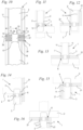
- Fig. 10 shows an exemplary embodiment of a thermally insulating component 6, which is arranged between a first structural part 2 and a second structural part 3.
- the thermally insulating component is Fig. 10
- the thrust bearing 10 is arranged centrally between the end faces 26 and 27 of the insulating body 7.
- the thrust bearing 10 is therefore arranged centrally in relation to the transverse direction 28 of the insulation joint 4.
- a tension rod 11 runs between each side of the thrust bearing 10 and the facing end face 26 or 27 of the insulating body 7.
- Fig. 11 to 16 show the thermally insulating component 6 Fig. 10 in different installation variants.
- One of the building parts 2, 3 is designed as a floor ceiling or foundation and runs horizontally.
- the tension rods 11 are connected to one another in this horizontally extending building part 2 or 3 and are designed as an arch, so that overall there is a U-shaped design of the tension element and both tension rods 11 form a common force-transmitting element.
- a thrust bearing 10 and two transverse force rods 30 arranged in pairs are provided.
- the transverse force bars 30 run obliquely to the vertical in the area of the insulating body 7.
- the transverse force bars 30 cross each other in the longitudinal direction 5 of the insulation joint 4 in the area of the thrust bearing 10, preferably in the middle.
- the ends of the transverse force rods 30 each run parallel to one another and form anchoring sections 12 which are embedded in the first structural part 2 and in the second structural part 3.
- the thermally insulating component 6 Fig. 17 serves primarily to transmit compressive forces F D and shear forces F Q1 , F Q2 ( Fig. 1 ) between building parts 2 and 3.
- Fig. 18 to 23 show an embodiment variant of the thermally insulating component 6, in which the transverse force bars 30 are connected to one another in the structural part that is horizontally aligned and thus form a bow-shaped anchoring section 12.
- Fig. 24 shows a thermally insulating component corresponding to Fig. 17 , with two additional tension rods 11 being provided.
- the component 6 is constructed symmetrically, with a tension rod 10 running between the thrust bearing 10 and each end face 26, 27 of the insulating body 7.
- the Fig. 25 to 30 show the thermally insulating component 6 Fig. 24 in different installation variants.
- the thermally insulating component 6 is modified in such a way that the two tension rods 11 and the two transverse force rods 30 are connected to one another in the structural part 2, 3, which is designed as a horizontal plate, so that a reinforcement loop results.
- Fig. 31 shows an exemplary embodiment of a thermally insulating component 6, which comprises an insulating body 7, two tension rods 11 arranged in pairs and a thrust bearing 40.
- the thrust bearing 40 protrudes slightly into the structural parts 2 and 3.
- the thrust bearing 40 can also end flush with the insulating body 7 and not protrude into the structural parts 2 and 3.
- the thrust bearing 40 is not designed to transmit forces in the longitudinal direction 5 or transverse direction 28 of the insulation joint 4.
- the two tension rods 11 are arranged on both sides of the thrust bearing 40 in a sectional plane perpendicular to the longitudinal direction 5.
- the tension rods 11 and the thrust bearing 40 are advantageously arranged in the same cross section. However, an arrangement with a distance or offset in the longitudinal direction 5 can also be provided.
- a plurality of tension rods 11 and thrust bearings 40 arranged in pairs are advantageously provided along the length of the insulating body 7.
- the thrust bearing 40 is arranged centrally in the insulating body 7 with respect to the transverse direction 28.
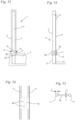
- the Fig. 32 to 37 show different installation variants of the thermally insulating component Fig. 31 , wherein the two tension rods 11 are connected to one another to form an anchoring section 12 in the structural part 2 or 3, which runs horizontally, and form a loop for anchoring.
- the thermally insulating component 6 has, in addition to an insulating body 7 and at least one thrust bearing 40, transverse force rods 30, which are each arranged in pairs and crossing one another. Is one of the building parts 2 or 3 designed as a floor or foundation, as in the Fig. 39 to 44 , the transverse force bars 30 are connected to one another in this structural part 2, 3 and form a loop as an anchoring section 12.
- the exemplary embodiments according to Fig. 45 to 51 show thermally insulating components 6 with an insulating body 7, at least one thrust bearing 40, pairs of intersecting transverse force rods 30 and two tension rods 11 assigned to each thrust bearing 40.
- the shear force rods 30 and the tension rods 11 are each connected to one another in the building part 2 or 3 designed as a floor ceiling or foundation to form an anchoring section 12.
- Fig. 52 shows a building 1 with building parts 2 and 3, in whose insulation joint 4 an insulating body 7 runs.
- Tension rods 11 are provided for power transmission
- Fig. 53 shows, each connected to one another via a push plate.
- the push plate 50 is arranged completely in the insulating body 7 and the tension rods 11 protrude through the insulating body 7 from the long side 19 to the long side 20.
- the tension rods 11 protrude into the building parts 2 and 3 and are in these over the surrounding concrete of the building parts 2 and 3 anchored.
- the push plate 50 can have recesses 49.
- Fig. 52 and Fig. 53 show, the tension rods 11 can each be connected to one another at their free ends.
- the tension rods 11 have a diameter m that is larger than the thickness k of the push plate 50, like Fig. 55 shows.
- the thrust plate 50 is arranged perpendicular to the longitudinal direction 5 of the insulation joint 4.
- the push plate 50 runs like this Fig. 55 shows, between the tension rods 11.
- the tension rods 11 form a force-transmitting element with the thrust plate 50, which is at a lateral distance from the end faces 26 and 27 of the insulating body 7, like Fig. 53 shows.
- thermally insulating components 6 which have tension rods 11 and crossed transverse force rods 30 arranged in pairs as force-transmitting elements.
- the parapet is referred to as the first structural part 2 and the floor ceiling underneath is referred to as the second structural part 3.
- a thermally insulating component designed in this way can also be arranged as a connecting element in other installation situations in an insulating joint 4 between two structural parts 2 and 3. This is schematic in the Fig. 57 to 62 shown.
- the force-transmitting elements are arranged at a distance from one another in the insulating body 7.
- the thrust bearings 40 or thrust bearings 10 are not directly connected to transverse force bars 30 or tension bars 11.
- the thrust bearings 40 or thrust bearings 10 can be at a distance from the insulating joint 4 in the transverse direction 28 and/or in the longitudinal direction 5.
- the thrust bearings 40 are designed to transmit pressure forces F D. Transverse forces F Q1 , F Q2 cannot be transmitted by the thrust bearings 40 to a relevant level.
- the thrust thrust bearings 10 are designed to transmit compressive forces F D and transverse forces F Q1 , F Q2 .
- Tension rods 11 are designed to transmit tensile forces F Z.
- Transverse force bars 30 are designed to transmit transverse forces F Q1 , F Q2 .
- the force-transmitting elements are preferably arranged symmetrically with respect to a plane that runs centrally between the end faces 26 and 27 of the insulating body 7.
- the thrust bearings 40 and/or the thrust thrust bearings 10 are advantageously arranged centrally between the end faces 26 and 27.
Landscapes
- Engineering & Computer Science (AREA)
- Architecture (AREA)
- Physics & Mathematics (AREA)
- Electromagnetism (AREA)
- Civil Engineering (AREA)
- Structural Engineering (AREA)
- Acoustics & Sound (AREA)
- Building Environments (AREA)
Abstract
Description
- Die Erfindung betrifft ein Bauwerk mit einem thermisch isolierenden Bauelement.
- Es ist bekannt, zwischen aneinander angrenzenden Bauwerksteilen thermisch isolierende Bauelemente anzuordnen, um eine verbesserte Wärmeisolierung zu erreichen. Derartige thermisch isolierende Bauelemente können in vertikaler Richtung zwischen einer Wand oder Stütze und einer Decke oder einem Fundament angeordnet werden. Für diesen Anwendungsfall ist es bekannt, thermisch isolierende Bauelemente vorzusehen, die nach Art eines Mauersteins gestaltet sind.
- Aus der
EP 2 151 531 A2 ist ein derartiger wärmedämmender Mauerstein bekannt. Als Stützorgane sind freistehende Tragsäulen vorgesehen, die sich von der unteren bis zur oberen Auflagefläche des Wärmedämmkörpers des Mauersteins erstrecken. - Es sind auch wärmedämmende Bauelemente bekannt, die zur Anordnung zwischen horizontal benachbarten Bauwerksteilen vorgesehen sind. Derartige wärmedämmende Bauelemente werden beispielsweise zur Anbindung von auskragenden Bauwerksteilen wie Balkonen oder dergleichen eingesetzt. Ein solches thermisch isolierendes Bauelement ist beispielsweise aus der
EP 1 892 344 A1 bekannt. - Der vorliegenden Erfindung liegt die Aufgabe zugrunde, ein Bauwerk anzugeben, das einen vorteilhaften Aufbau besitzt.
- Diese Aufgabe wird bezüglich des Bauwerks durch ein Bauwerk mit den Merkmalen des Anspruchs 1 gelöst.
- Die Erfindung betrifft die Gestaltung mindestens eines kraftübertragenden Elements durch zwei Zugstäbe, die über ein mindestens teilweise in dem Isolierkörper angeordnetes Schubblech kraftübertragend miteinander verbunden sind. Diese Gestaltung eines kraftübertragenden Elements ist unabhängig von der Gestaltung weiterer kraftübertragender Elemente, insbesondere unabhängig von der Gestaltung weiterer kraftübertragender Elemente zur Übertragung von Druckkräften und/oder von Querkräften.
- Über ein kraftübertragendes Element aus zwei Zugstäben, die über ein Schubblech kraftübertragend miteinander verbunden sind, können sowohl Zugkräfte als auch Querkräfte über die Dämmfuge übertragen werden. Aufgrund des geringen Querschnitts des Schubblechs ergibt sich eine gute Dämmwirkung. Das kraftübertragende Element aus zwei Zugstäben und einem Schubblech weist außerdem einen einfachen Aufbau auf. Die Zugstäbe sind bevorzugt an gegenüberliegenden Hochkanten des Schubblechs angeordnet. Die in Längsrichtung der Dämmfuge gemessene Dicke des Schubblechs ist bevorzugt kleiner als der Durchmesser mindestens eines Zugstabs. Dadurch kann eine gute Dämmwirkung erreicht werden.
- Der Isolierkörper des thermisch isolierenden Bauelements ist bevorzugt länglich ausgebildet und besitzt gegenüber üblichen Mauerwerkssteinen eine deutlich größere Länge. Dies ist insbesondere für die Verbindung einer Wand mit einer Decke oder einem Fundament vorteilhaft. Die Anzahl der über die Länge der Wand benötigten thermisch isolierenden Bauelemente kann dadurch gering gehalten werden. Die in Längsrichtung der Dämmfuge gemessene Länge des Isolierkörpers beträgt vorteilhaft mindestens das 5fache der Höhe des Isolierkörpers. Die Höhe des Isolierkörpers ist dabei von der ersten Längsseite zur zweiten Längsseite in vertikaler Richtung gemessen. Die in Längsrichtung der Dämmfuge gemessene Länge des Isolierkörpers entspricht dabei vorteilhaft der in Längsrichtung der Dämmfuge gemessenen Länge des thermisch isolierenden Bauelements.
- Vorteilhaft weist die in Längsrichtung der Dämmfuge gemessene Länge des Isolierkörpers mindestens das 5fache der in Querrichtung der Dämmfuge und horizontal gemessenen Breite des Isolierkörpers auf.
- Für die Anbindung einer Stütze können auch thermisch isolierende Bauelemente zum Einsatz kommen, deren Isolierkörper eine Länge aufweist, die der Breite des Isolierkörpers näherungsweise entspricht. Für die Anbindung einer Stütze kann die Länge des Isolierkörpers beispielsweise ein Drittel bis das 3fache der Breite des Isolierkörpers betragen.
- Vorteilhaft sind alle kraftübertragenden Elemente des thermisch isolierenden Bauelements separat voneinander ausgebildet und durch den Isolierkörper voneinander getrennt. Insbesondere sind die Druckschublager und Drucklager von Zugstäben und Querkraftstäben getrennt ausgebildet. Die Zugstäbe und Querkraftstäbe weisen zu den Drucklagern und/oder Druckschublagern in Längsrichtung der Dämmfuge vorteilhaft einen Abstand auf.
- Ausführungsbeispiele der Erfindung werden im Folgenden anhand der Zeichnung erläutert. Es zeigen:
- Fig. 1
- eine schematische Darstellung eines Bauwerks mit einem nicht erfindungsgemäßen thermisch isolierenden Bauelement,
- Fig. 2
- eine schematische Darstellung eines Bauwerks mit einem weiteren nicht erfindungsgemäßen thermisch isolierenden Bauelement in Abwandlung der Ausführung nach
Fig. 1 , - Fig. 3 bis Fig. 7
- schematische Darstellungen von Bauwerken mit dem thermisch isolierenden Bauelement aus
Fig. 2 , - Fig. 8
- eine schematische Darstellung der Ausführung nach
Fig. 1 in Richtung des Pfeils VIII inFig. 1 , - Fig. 9
- eine ausschnittsweise vergrößerte schematische Darstellung der Ausführung nach
Fig. 1 im Bereich des Isolierkörpers, - Fig. 10
- eine schematische Darstellung eines Bauwerks mit einer weiteren nicht erfindungsgemäßen Ausführung eines thermisch isolierenden Bauelements,
- Fig. 11
- eine schematische Darstellung eines weiteren Bauwerks mit einem nicht erfindungsgemäßen thermisch isolierenden Bauelement in Abwandlung der Ausführung nach
Fig. 10 , - Fig. 12 bis Fig. 16
- schematische Darstellungen von Bauwerken mit dem thermisch isolierenden Bauelement aus
Fig. 11 , - Fig. 17
- eine schematische Darstellung eines Bauwerks mit einem nicht erfindungsgemäßen thermisch isolierenden Bauelement,
- Fig. 18
- eine schematische Darstellung eines Bauwerks mit einem nicht erfindungsgemäßen thermisch isolierenden Bauelement in Abwandlung des Ausführungsbeispiels nach
Fig. 17 , - Fig. 19 bis Fig. 23
- schematische Darstellungen von Bauwerken mit dem thermisch isolierenden Bauelement gemäß
Fig. 18 , - Fig. 24
- ein weiteres Ausführungsbeispiel eines Bauwerks mit einem nicht erfindungsgemäßen thermisch isolierenden Bauelement in schematischer Darstellung,
- Fig. 25
- eine schematische Darstellung eines weiteren Bauwerks mit einem nicht erfindungsgemäßen thermisch isolierenden Bauelement in Abwandlung des Ausführungsbeispiels nach
Fig. 24 , - Fig. 26 bis Fig. 30
- schematische Darstellungen von Ausführungsbeispielen von Bauwerken mit dem thermisch isolierenden Bauelement aus
Fig. 25 , - Fig. 31
- ein Bauwerk mit einem nicht erfindungsgemäßen thermisch isolierenden Bauelement in schematischer Darstellung,
- Fig. 32
- eine schematische Darstellung eines weiteren Bauwerks mit einem nicht erfindungsgemäßen thermisch isolierenden Bauelement in Abwandlung des Ausführungsbeispiels nach
Fig. 31 , - Fig. 33 bis Fig. 37
- schematische Darstellungen von Bauwerken mit dem thermisch isolierenden Bauelement aus
Fig. 32 , - Fig. 38
- ein Bauwerk mit einem nicht erfindungsgemäßen thermisch isolierenden Bauelement in schematischer Darstellung,
- Fig. 39
- eine schematische Darstellung eines weiteren Bauwerks mit einem nicht erfindungsgemäßen thermisch isolierenden Bauelement in Abwandlung des Ausführungsbeispiels nach
Fig. 38 , - Fig. 40 bis Fig. 44
- schematische Darstellungen von Bauwerken mit dem nicht erfindungsgemäßen thermisch isolierenden Bauelement aus
Fig. 39 , - Fig. 45
- ein Bauwerk mit einem nicht erfindungsgemäßen thermisch isolierenden Bauelement in schematischer Darstellung,
- Fig. 46
- eine schematische Darstellung eines weiteren Bauwerks mit einem nicht erfindungsgemäßen thermisch isolierenden Bauelement in Abwandlung des Ausführungsbeispiels nach
Fig. 45 , - Fig. 47 bis Fig. 51
- schematische Darstellungen von Ausführungsbeispielen von Bauwerken mit dem nicht erfindungsgemäßen thermisch isolierenden Bauelement aus
Fig. 46 , - Fig. 52
- eine schematische Darstellung eines Ausführungsbeispiels eines Bauwerks mit einem thermisch isolierenden Bauelement,
- Fig. 53
- eine schematische Darstellung des thermisch isolierenden Bauelements aus
Fig. 52 , - Fig. 54
- eine vergrößerte Darstellung eines Ausschnitts des kraftübertragenden Elements aus
Fig. 53 , - Fig. 55
- eine schematische Draufsicht auf das kraftübertragende Element aus
Fig. 54 , - Fig. 56
- eine schematische Darstellung eines Bauwerks mit einem thermisch isolierenden Bauelement nach dem Stand der Technik,
- Fig. 57 bis Fig. 62
- weitere mögliche Anordnungen des thermisch isolierenden Bauelements aus
Fig. 56 . -
Fig. 1 zeigt schematisch ein Bauwerk 1 mit einem ersten Bauwerksteil 2 und einem zweiten Bauwerksteil 3. Das erste Bauwerksteil 2 kann eine Wand oder Stütze sein. Auch das zweite Bauwerksteil 3 kann eine Wand oder Stütze sein. Andere mögliche Ausführungen für die beiden Bauwerksteile 2 und 3 sind in den folgenden Figuren gezeigt. Das erste Bauwerksteil 2 verläuft bezogen auf die Senkrechte S über dem zweiten Bauwerksteil 3. Im Ausführungsbeispiel nachFig. 1 sind das erste Bauwerksteil 2 und das zweite Bauwerksteil 3 senkrecht ausgerichtet, und das erste Bauwerksteil 2 ist über dem zweiten Bauwerksteil 3 angeordnet. Die Bauwerksteile 2 und 3 bestehen aus Beton, vorteilhaft aus Ortbeton. - Die Bauwerksteile 2 und 3 sind über ein thermisch isolierendes Bauelement 6 miteinander verbunden. Das thermisch isolierende Bauelement weist einen Isolierkörper 7 auf. Zwischen den Bauwerksteilen 2 und 3 ist eine Dämmfuge 4 ausgebildet. Der Isolierkörper 7 des thermisch isolierenden Bauelements 6 ist in der Dämmfuge 4 zwischen den Bauwerksteilen 2 und 3 angeordnet. Der Isolierkörper 7 weist eine erste, oben verlaufende Längsseite 19 sowie eine zweite, unten verlaufende Längsseite 20 auf. Im Ausführungsbeispiel liegt die erste Längsseite 19 vollständig senkrecht über der zweiten Längsseite 20. Es kann auch vorgesehen sein, dass die Bauwerksteile 2 und 3 gegenüber der Darstellung in
Fig. 1 gekippt verlaufen, beispielsweise bei der Anbindung einer geneigten Wand oder eines geneigt verlaufenden Dachabschnitts. Die erste Längsseite 19 verläuft auch bei geneigter Anordnung zumindest teilweise senkrecht über der zweiten Längsseite 20. Der Isolierkörper 7 weist einander gegenüberliegende Stirnseiten 26 und 27 auf. Die Stirnseiten 26 und 27 des Isolierkörpers 7 erstrecken sich jeweils von der ersten Längsseite 19 zur zweiten Längsseite 20 des Isolierkörpers 7. Bei der inFig. 1 dargestellten Einbausituation verlaufen die Stirnseiten 26 und 27 vertikal. Die Stirnseiten 27 und 27 verlaufen vorteilhaft bündig zu den Innenseiten und Außenseiten der Bauwerksteile 2 und 3. - Zur Übertragung von Kräften zwischen den Bauwerksteilen 2 und 3 weist das thermisch isolierende Bauelement 6 kraftübertragende Elemente auf, die den Isolierkörper 7 zumindest von der ersten Längsseite 19 bis zur zweiten Längsseite 20 durchragen. Bevorzugt stehen zumindest einige der kraftübertragenden Elemente über die Längsseiten 19 und 20 hinaus und ragen in die Bauwerksteile 2 und 3 ein. Die kraftübertragenden Elemente sind bevorzugt vom Beton der Bauwerksteile 2 und 3 umgeben, so dass sich eine gute Kraftübertragung zwischen dem Beton und den kraftübertragenden Elementen ergibt. Im Ausführungsbeispiel sind als kraftübertragende Elemente Druckschublager 10 sowie Zugstäbe 11 vorgesehen. In
Fig. 1 ist schematisch ein Zugstab 11 und ein Druckschublager 10 gezeigt. Vorteilhaft sind mehrere Zugstäbe 11 und mehrere Druckschublager 10 in Längsrichtung 5 der Dämmfuge 4 jeweils mit Abstand zueinander vorgesehen. - Das Druckschublager 10 weist zwei Vorsprünge 15 und 16 auf, die über die erste Längsseite 19 in das erste Bauwerksteil 2 hervorstehen. An der gegenüberliegenden Seite weist das Druckschublager 10 Vorsprünge 17 und 18 auf, die in das zweite Bauwerksteil 3 ragen. Bezogen auf die Einbaulage sind die Vorsprünge 15 und 16 an der Oberseite und die Vorsprünge 17 und 18 an der Unterseite des Druckschublagers 10 angeordnet.
- Der Zugstab 11 weist Verankerungsabschnitte 12 auf, die in die Bauwerksteile 2 und 3 ragen. Im Ausführungsbeispiel ist der Zugstab 11 als gerader Stab ausgebildet und die Verankerungsabschnitte 12 als vergleichsweise lange, gerade Abschnitte des Zugstabs 11. Auch eine andere Ausbildung der Verankerungsabschnitte 12 kann vorgesehen sein.
- Über die Dämmfuge 4 sind Druckkräfte FD, Zugkräfte FZ sowie Querkräfte FQ1, FQ2 in beide Richtungen zu übertragen. Die Druckkraft FD und die Zugkraft FZ wirken parallel zur Senkrechten S. Die Querkräfte FQ1 und FQ2 wirken im Ausführungsbeispiel in Querrichtung 28 der Dämmfuge 4 und in horizontaler Richtung, also senkrecht zur Senkrechten S. Zur Übertragung der Druckkraft FD und der Querkräfte FQ1, FQ2 ist das mindestens eine Druckschublager 10 vorgesehen. Die Zugkraft FZ wird über den mindestens einen Zugstab 11 übertragen. Die Dämmfuge 4 weist eine Längsrichtung 5 auf, die in der Darstellung in
Fig. 1 senkrecht zur Blattebene verläuft. Die Längsrichtung 5 verläuft horizontal zwischen den Längsseiten 19 und 20 und zwischen den Stirnseiten 26 und 27 des Isolierkörpers 7. Die Längsrichtung 5 verläuft senkrecht zu einer Querrichtung 28 des Bauelements 6. Die Querrichtung 28 verläuft horizontal und, bei der inFig. 1 dargestellten Einbaulage, senkrecht zu den Stirnseiten 26 und 27. Bei geneigtem Einbau des thermisch isolierenden Bauelements 6 kann die Querrichtung 28 zu den Stirnseiten 26 und 27 geneigt verlaufen. - Das Druckschublager 10 besteht aus gießfähigem, nichtmetallischem Material. Das gießfähige, nichtmetallische Material ist vorteilhaft hochfester Beton oder hochfester Mörtel. Dadurch können über das Druckschublager 10 sehr große Druckkräfte FD und Querkräfte FQ1, FQ2 bei geringem Querschnitt des Druckschublagers 10 übertragen werden. Besonders bevorzugt ist das gießfähige, nichtmetallische Material ultrahochfester Beton oder ultrahochfester Mörtel. In vorteilhafter Gestaltung ist das gießfähige, nichtmetallische Material faserverstärkt. Die Fasern können beispielsweise Metallfasern oder Kohlestofffasern sein. Auch eine Faserverstärkung aus anderen Materialien kann vorteilhaft sein.
- Das Druckschublager 10 weist einander gegenüberliegende Stirnseiten 35 und 36 auf, die sich im Ausführungsbeispiel vertikal und parallel zur Längsrichtung 5 der Dämmfuge 4 erstrecken. Die Stirnseiten 35 und 36 verlaufen im Ausführungsbeispiel parallel zu den Stirnseiten 26 und 27 des Isolierkörpers 7. Im Ausführungsbeispiel sind die Stirnseiten 35 und 36 eben ausgebildet und weisen einen konstanten Abstand zueinander auf. Auch eine andere Gestaltung der Stirnseiten 35 und 36 des Druckschublagers 10 kann jedoch vorteilhaft sein. Die Stirnseiten 35 und 36 können beispielsweise abschnittsweise oder über ihre gesamte Länge zueinander geneigt verlaufen. Bevorzugt weist das Druckschublager an mindestens einer Stelle innerhalb des Isolierkörpers 7 eine verringerte Erstreckung in Längsrichtung, Querrichtung und/oder senkrechter Richtung auf. Dadurch kann die Wärmeübertragung zwischen den Bauwerksteilen 2 und 3 verringert und die Isolierwirkung verbessert werden.
-
Fig. 2 zeigt schematisch einen Ausschnitt eines Bauwerks 1, beispielsweise eines Gebäudes, mit einem ersten, senkrecht verlaufenden Bauwerksteil 2, beispielsweise einer Wand oder Stütze, sowie einem zweiten, horizontal verlaufenden Bauwerksteil 3, beispielsweise einer Geschossdecke oder einem Fundament. In einer Dämmfuge 4 zwischen den Bauwerksteilen 2 und 3 ist der Isolierkörper 7 eines thermisch isolierenden Bauelements 6 angeordnet, das ähnlich zu dem inFig. 1 dargestellten thermisch isolierenden Bauelement 6 ausgebildet ist. Im Unterschied zu dem thermisch isolierenden Bauelement 6 ausFig. 1 ist der mindestens eine Zugstab 11 des thermisch isolierenden Bauelements 6 ausFig. 2 lediglich an dem in das erste Bauwerksteil 2 ragenden Verankerungsabschnitt 12 gerade ausgebildet. Der in das zweite Bauwerksteil 3 ragende Verankerungsabschnitt 12 ist mit einem abgewinkelten Abschnitt 14 versehen, der vergleichsweise kurz ausgebildet ist und an seinem Ende einen abgeflachten Ankerkopf 13 trägt. Dadurch kann in geringerem Abstand zum Isolierkörper 7 eine Verankerung im Beton des Bauwerksteils 3 erreicht werden. Das zweite Bauwerksteil 3 verläuft beim Ausführungsbeispiel nachFig. 2 horizontal, so dass für die Verankerung weniger Platz in vertikaler Richtung zur Verfügung steht als beim Ausführungsbeispiel nachFig. 1 . -
Fig. 3 zeigt einen Ausschnitt eines Bauwerks 1, bei dem die Bauwerksteile 2 und 3 sowie das thermisch isolierende Bauelement 6 entsprechend zuFig. 2 angeordnet sind. Gleiche Bezugszeichen bezeichnen dabei in allen Figuren einander entsprechende Elemente. Das erste Bauwerksteil 2 trägt eine zusätzliche Isolierung aus Dämmmaterial 21. Das Dämmmaterial 21 ist bevorzugt an einer Außenseite 31 des als Wand aus Beton ausgebildeten Bauwerksteils 2 vorgesehen. Von der gegenüberliegenden Innenseite 32 des Bauwerksteils 2 erstreckt sich das zweite Bauwerksteil 3. Das zweite Bauwerksteil 3 trägt auf seiner Oberseite 33 Dämmmaterial 21. Das Dämmmaterial 21 an der Oberseite 33 verläuft in Verlängerung des Isolierkörpers 7 des thermisch isolierenden Bauelements 6 und weist im Ausführungsbeispiel die gleiche Höhe auf wie der Isolierkörper 7. Der Isolierkörper 7 erstreckt sich bis an das an der Außenseite 31 des Bauwerksteils 2 angebrachte Dämmmaterial 21. Das zweite Bauwerksteil 3 ist bei dieser Anordnung bevorzugt ein Fundament. -
Fig. 4 zeigt eine Anordnung des thermisch isolierenden Bauelements 6, bei der das erste Bauwerksteil 2 eine Wand oder Stütze ist, die sich von einem mittigen Bereich des zweiten Bauwerksteils 3 erhebt. Der Isolierkörper 7 des thermisch isolierenden Bauelements 6 ist im Fußbereich des Bauwerksteils 2 und zwischen den Bauwerksteilen 2 und 3 angeordnet. Das zweite Bauwerksteil 3 kann beispielsweise ein Fundament sein. Das zweite Bauwerksteil 3 trägt an seiner Oberseite 33 Dämmmaterial 21, das an den Isolierkörper 7 des Bauelements 6 beidseitig anschließt und bevorzugt die gleiche Höhe wie der Isolierkörper 7 hat. - Beim Ausführungsbeispiel nach
Fig. 5 ist das thermisch isolierende Bauelement 6 zwischen einem als Geschossdecke ausgebildeten ersten Bauwerksteil 2 sowie einem als Wand oder Stütze ausgebildeten zweiten Bauwerksteil 3 angeordnet. Das zweite Bauwerksteil 3 verläuft im Wesentlichen vertikal und das erste Bauwerksteil 2 im Wesentlichen horizontal. Der abgewinkelte Abschnitt 14 des thermisch isolierenden Bauelements 6 ragt in das erste Bauwerksteil 2 und bezogen auf die Einbaulage vom Isolierkörper 7 nach oben. Die Bauwerksteile 2 und 3 sind beispielsweise zu einer Gebäudeaußenseite hin von Dämmmaterial 21 abgedeckt, das sich sowohl am ersten Bauwerksteil 2 als auch am Isolierkörper 7 und am zweiten Bauwerksteil 3 durchgehend erstreckt. -
Fig. 6 zeigt die Anordnung des thermisch isolierenden Bauelements 6 zwischen einem ersten Bauwerksteil 2, das eine Gebäudedecke bildet, sowie einem zweiten Bauwerksteil 3, das als Wand oder Stütze ausgebildet sein kann. Das erste Bauwerksteil 2 ist horizontal ausgerichtet und das zweite Bauwerksteil 3 vertikal. Das erste Bauwerksteil 2 verläuft oberhalb des zweiten Bauwerksteils 3. Der abgewinkelte Abschnitt 14 des Zugstabs 11 ragt in das erste Bauwerksteil 2. An der Außenseite 31 des zweiten Bauwerksteils 3 und an einer Unterseite des ersten Bauwerksteils 2 erstreckt sich Dämmmaterial 21. Der Isolierkörper 7 ist zwischen dem an der Außenseite 31 des Bauwerksteils 3 und dem an der Unterseite 34 des Bauwerksteils 2 angeordneten Dämmmaterial 21 angeordnet. -
Fig. 7 zeigt eine entsprechende Anordnung, bei der das erste Bauwerksteil 2 sich vom zweiten Bauwerksteil 3 in beide Richtungen erstreckt und nicht, wie inFig. 6 , oberhalb der Außenseite 31 endet. -
Fig. 8 zeigt schematisch die Anordnung des thermisch isolierenden Bauelements 6 in einer Dämmfuge 4 in Seitenansicht. In der schematischen Darstellung sind die Zugstäbe 11 und Druckschublager 10 dargestellt, obwohl diese in der tatsächlichen Ausführung vorzugsweise nicht bis an eine Stirnseite 26, 27 des Isolierkörpers 7 ragen und daher in einer Seitenansicht nicht sichtbar sind. WieFig. 8 zeigt, sind mehrere Druckschublager 10 in regelmäßigem Abstand zueinander vorgesehen, die den Isolierkörper 7 von der ersten Längsseite 18 zur zweiten Längsseite 20 durchragen und an der ersten Längsseite 19 und der zweiten Längsseite 20 mit ihren Vorsprüngen 15, 16, 17, 18 über die Längsseiten 19 und 20 in die Bauwerksteile 2 und 3 hineinragen. - Die Druckschublager 10 besitzen quer zur Längsrichtung 5 der Dämmfuge 4 verlaufende Querseiten 37 und 38. Im Ausführungsbeispiel verlaufen die Querseiten 37 und 38 parallel zueinander, so dass die Erstreckung des Druckschublagers 10 in Längsrichtung der Dämmfuge 4 konstant ist. Die Querseiten 37 und 38 können jedoch auch geneigt zueinander verlaufen, so dass die Erstreckung des Druckschublagers 10 in Längsrichtung der Dämmfuge 4 sich in horizontaler und/oder vertikaler Richtung ändert. Insbesondere ist an einer oder beiden Querseiten 37, 38 eine Ausnehmung vorgesehen, an der die Erstreckung des Druckschublagers 10 verringert ist.
- In der Ansicht in
Fig. 8 sind die Vorsprünge 15 und 17 dargestellt und die Vorsprünge 16 und 18 befinden sich hinter der Zeichenebene. Bei der dargestellten Blickrichtung in Querrichtung 28 der Dämmfuge 4 (Fig. 9 ) sind die Vorsprünge 15, 16, 17 und 18 abgerundet ausgebildet. Über die Vorsprünge 15 bis 18 können daher Längskräfte FL nicht oder nicht wesentlich übertragen werden. Längskräfte FL sind Kräfte, die in Längsrichtung 5 der Dämmfuge 4 wirken. Druckkräfte FD werden von den Druckschublagern 10 übertragen. In geringem Abstand zu jedem Druckschublager 10 ist ein Zugstab 11 angeordnet. Zugkräfte FZ werden über die Zugstäbe 11 übertragen. Der Abstand zwischen benachbarten Druckschublagern 10 ist deutlich größer als der Abstand zwischen einem Druckschublager 10 und dem benachbarten Zugstab 11. Der Isolierkörper 7 weist, wieFig. 8 zeigt, eine längliche Gestalt auf. Der Isolierkörper 7 besitzt eine Länge p, die in Längsrichtung 5 der Dämmfuge 4 gemessen ist. Der Isolierkörper 7 besitzt außerdem eine Höhe r, die in Richtung der Senkrechten S gemessen ist. Die Länge p ist deutlich größer als die Höhe r. Vorteilhaft beträgt die Länge p mindestens das 5fache der Höhe r. - In
Fig. 9 ist die Gestaltung des Isolierkörpers 7 des thermisch isolierenden Bauelements 6 aus denFig. 1 bis 8 im Einzelnen gezeigt. Der Isolierkörper 7 weist die beiden einander gegenüberliegenden Stirnseiten 26 und 27 auf, die die Längsseiten 19 und 20 miteinander verbinden. Im Ausführungsbeispiel ist der Isolierkörper 7 durch einen Verwahrkasten 8 gebildet, in dem Dämmmaterial 9 angeordnet ist. Der Verwahrkasten 8 besteht vorteilhaft aus Kunststoff und ist insbesondere aus Kunststoffstrang-Pressprofilen aufgebaut. Im Ausführungsbeispiel weist der Verwahrkasten 8 an den Längsseiten 19 und 20 und benachbart zu den Stirnseiten 26 und 27 Längsstege 29 auf. - Der Isolierkörper 7 weist eine in Querrichtung 28 gemessene Breite e auf. Die Breite e entspricht vorteilhaft der Breite der Dämmfuge 4. Die Breite e entspricht vorteilhaft der Breite des Bauwerksteils 2, 3, das die geringere Erstreckung in Querrichtung 28 aufweist, so dass die Bauwerksteile 2 und 3 die Dämmfuge 4 über die gesamte Breite e des Isolierkörpers 7 begrenzen. Die Länge p des Isolierkörpers 7 beträgt vorteilhaft mindestens das 5fache der Breite e des Isolierkörpers 7. Dies ist insbesondere dann vorteilhaft, wenn das thermisch isolierende Bauelement 6 zur Verbindung einer Wand mit einer Decke oder einem Fundament eingesetzt wird. Bei der Anbindung einer Stütze an eine Decke oder ein Fundament können andere Abmessungen des Isolierkörpers 7, insbesondere eine deutlich geringere Länge p des Isolierkörpers 7 vorteilhaft sein.
- Wie
Fig. 9 auch zeigt, sind das mindestens eine Druckschublager 10 und der mindestens eine Zugstab 11 in dem Verwahrkasten 8 gehalten. InFig. 9 sind das Druckschublager 10 und der Zugstab 11 im gleichen Querschnitt ohne Abstand in Längsrichtung 5 der Dämmfuge 4 dargestellt. Es kann vorgesehen sein, dass Zugstab 11 und Druckschublager 10 im gleichen Querschnitt senkrecht zur Längsrichtung 5 angeordnet sind oder dass Zugstab 11 und Druckschublager 10 in Längsrichtung 5 einen Abstand zueinander aufweisen, wie inFig. 9 dargestellt. - Wie
Fig. 9 auch zeigt, weist der Vorsprung 15 eine Druckfläche 22 auf, der Vorsprung 16 eine Druckfläche 23, der Vorsprung 17 eine Druckfläche 24 und der Vorsprung 18 eine Druckfläche 25. Die Druckfläche 22 ist zur Aufnahme von Querkräften FQ2 vorgesehen, die in Richtung von der Stirnseite 27 auf das erste Bauwerksteil 2 wirken. Die Druckfläche 25 des Vorsprungs 18 überträgt diese Kräfte in das zweite Bauwerksteil 3. Entsprechend wirken die Druckflächen 23 und 24 der Vorsprünge 16 und 17 zur Übertragung von Querkräften FQ1 vom ersten Bauwerksteil 2 zum zweiten Bauwerksteil 3 zusammen, die in Richtung von der Stirnseite 26 auf das erste Bauwerksteil 2 wirken. Der erste Vorsprung 15 und der zweite Vorsprung 17 sind näher an der Stirnseite 26 des Isolierkörpers 7 angeordnet als die Vorsprünge 16 und 18. Die Vorsprünge 16 und 18 sind näher an der Stirnseite 27 angeordnet und von der Stirnseite 26 weiter entfernt als die Vorsprünge 15 und 17. Die Druckflächen 22 und 23 der Vorsprünge 15 und 16 sind einander zugewandt und bilden in Seitenansicht eine konkave Kontur. Entsprechend sind die Druckflächen 24 und 25 der Vorsprünge 17 und 18 einander zugewandt und bilden in Seitenansicht eine näherungsweise konkave Kontur. Die Druckflächen 22 bis 25 schließen mit der Horizontalen H, die im dargestellten Einbauzustand parallel zur Querrichtung 28 verläuft, einen Winkel α ein, der mindestens 20°, insbesondere mindestens 30° beträgt. Der Winkel α jeder Druckfläche 22 bis 25 öffnet dabei in Richtung auf die näher liegende Stirnseite 26 bzw. 27. Die Druckfläche 22 steigt zur Stirnseite 26 hin an und die Druckfläche 23 zur Stirnseite 27. Die Druckfläche 24 fällt zur Stirnseite 26 hin ab und die Druckfläche 25 zur Stirnseite 27 hin. - Um eine ausreichende Betonüberdeckung der Druckflächen 22, 23, 24 und 25 sicherzustellen, ist vorgesehen, dass die Druckfläche zu der Stirnseite 26, 27 des Isolierkörpers 7, von deren Seite eine von dieser Druckfläche 22 bis 25 aufzunehmende Querkraft FQ1, FQ2 wirkt, einen Abstand a, b, c, d von mindestens einem Drittel der in Querrichtung 28 der Dämmfuge 4 und horizontal gemessenen Breite e des Isolierkörpers 7 aufweist. Die Druckfläche 22 weist im Ausführungsbeispiel zur Stirnseite 27, von der die aufzunehmende Druckkraft FQ2 wirkt, einen Abstand a auf, der mehr als ein Drittel, insbesondere mehr als die Hälfte, bevorzugt mehr als zwei Drittel der Breite e beträgt. Die Druckfläche 24 ist symmetrisch zur Druckfläche 22 und in gleichem Abstand zur Stirnseite 27 angeordnet. Die Druckfläche 23 weist zur Stirnseite 26 einen Abstand b auf, der mehr als ein Drittel, insbesondere mehr als die Hälfte der Breite e des Isolierkörpers 7 beträgt. Die Druckfläche 25 ist symmetrisch zur Druckfläche 23 ausgebildet und in einem Abstand d zur Stirnseite 26 angeordnet, der dem Abstand e entspricht. Alle Abstände a, b, c, d sind dabei in horizontaler Richtung und parallel zur Querrichtung 28 gemessen.
- Die in Querrichtung 28 der Dämmfuge 4 gemessene Breite g jedes Vorsprungs 22 bis 25 beträgt vorteilhaft höchstens 40 % der in Querrichtung 28 gemessenen Breite i des Druckschublagers 10. Die in Längsrichtung 5 der Dämmfuge 4 gemessene Länge f jedes Vorsprungs 22 bis 25, die in
Fig. 8 gezeigt ist, beträgt vorteilhaft höchstens das Doppelte der Breite g des jeweiligen Vorsprungs 22 bis 25. Die Vorsprünge 22 bis 25 sind demnach kompakt ausgebildet. - Im Ausführungsbeispiel verlaufen die Stirnseiten 35, 36 des Druckschublagers 10 parallel zueinander. Dadurch ergibt sich eine konstante Breite i des Druckschublagers 10 über dessen gesamte Höhe r. Bei anderem Verlauf der Stirnseiten 35 und 36 kann die Breite sich über die Höhe r ändern. Die Breite i ist die Gesamtbreite des Druckschublagers 10.
- Im Ausführungsbeispiel weist jedes Druckschublager 10 vier Vorsprünge 15, 16, 17, 18 auf. Auch eine andere Anzahl von Vorsprüngen, beispielsweise genau ein Vorsprung an der ersten Längsseite 19 und genau ein Vorsprung an der zweiten Längsseite 20, kann vorteilhaft sein. Ist an einer Längsseite 19, 20 lediglich ein Vorsprung vorgesehen, so ist der Vorsprung vorteilhaft mittig zwischen den Stirnseiten 35 und 36 angeordnet. Insbesondere weist jeder Vorsprung zwei Druckflächen auf, die zu den gegenüberliegenden Stirnseiten 26, 27 des Isolierkörpers weisen.
-
Fig. 10 zeigt ein Ausführungsbeispiel eines thermisch isolierenden Bauelements 6, das zwischen einem ersten Bauwerksteil 2 und einem zweiten Bauwerksteil 3 angeordnet ist. Im Unterschied zu den in den vorangegangenen Ausführungsbeispielen gezeigten Bauelementen 6 ist beim thermisch isolierenden Bauelement nachFig. 10 das Druckschublager 10 mittig zwischen den Stirnseiten 26 und 27 des Isolierkörpers 7 angeordnet. Das Druckschublager 10 ist demnach bezogen auf die Querrichtung 28 der Dämmfuge 4 mittig angeordnet. Zwischen jeder Seite des Druckschublagers 10 und der zugewandten Stirnseite 26 bzw. 27 des Isolierkörpers 7 verläuft ein Zugstab 11. -
Fig. 11 bis 16 zeigen das thermisch isolierende Bauelement 6 ausFig. 10 in unterschiedlichen Einbauvarianten. Eines der Bauwerksteile 2, 3 ist dabei jeweils als Geschossdecke oder Fundament ausgebildet und verläuft horizontal. Die Zugstäbe 11 sind in diesem horizontal verlaufenden Bauwerksteil 2 oder 3 miteinander verbunden und als Bogen ausgeführt, so dass sich insgesamt eine U-förmige Gestaltung des Zugelements ergibt und beide Zugstäbe 11 ein gemeinsames kraftübertragendes Element bilden. - Beim Ausführungsbeispiel nach
Fig. 17 sind ein Druckschublager 10 sowie zwei paarweise angeordnete Querkraftstäbe 30 vorgesehen. Die Querkraftstäbe 30 verlaufen im Bereich des Isolierkörpers 7 schräg zur Vertikalen. Die Querkraftstäbe 30 kreuzen sich in Längsrichtung 5 der Dämmfuge 4 gesehen im Bereich des Druckschublagers 10, bevorzugt mittig. Die Enden der Querkraftstäbe 30 verlaufen jeweils parallel zueinander und bilden Verankerungsabschnitte 12, die im ersten Bauwerksteil 2 und im zweiten Bauwerksteil 3 eingebettet sind. Das thermisch isolierende Bauelement 6 ausFig. 17 dient überwiegend zur Übertragung von Druckkräften FD und Querkräften FQ1, FQ2 (Fig. 1 ) zwischen den Bauwerksteilen 2 und 3. - Die
Fig. 18 bis 23 zeigen eine Ausführungsvariante des thermisch isolierenden Bauelements 6, bei der die Querkraftstäbe 30 in dem Bauwerksteil, das horizontal ausgerichtet ist, miteinander verbunden sind und so einen bügelförmigen Verankerungsabschnitt 12 bilden. -
Fig. 24 zeigt ein thermisch isolierendes Bauelement entsprechend zurFig. 17 , wobei ergänzend zwei Zugstäbe 11 vorgesehen sind. Das Bauelement 6 ist symmetrisch aufgebaut, wobei zwischen dem Druckschublager 10 und jeder Stirnseite 26, 27 des Isolierkörpers 7 ein Zugstab 10 verläuft. DieFig. 25 bis 30 zeigen das thermisch isolierende Bauelement 6 ausFig. 24 in unterschiedlichen Einbauvarianten. Dabei ist das thermisch isolierende Bauelement 6 so modifiziert, dass jeweils die beiden Zugstäbe 11 und die beiden Querkraftstäbe 30 in dem Bauwerksteil 2, 3, das als horizontale Platte ausgebildet ist, miteinander verbunden sind, so dass sich eine Bewehrungsschlaufe ergibt. -
Fig. 31 zeigt ein Ausführungsbeispiel eines thermisch isolierenden Bauelements 6, das einen Isolierkörper 7, zwei paarweise angeordnete Zugstäbe 11 sowie ein Drucklager 40 umfasst. In der schematischen Darstellung ragt das Drucklager 40 in die Bauwerksteile 2 und 3 geringfügig hinein. Alternativ kann das Drucklager 40 auch bündig am Isolierkörper 7 enden und nicht in die Bauwerksteile 2 und 3 hineinragen. Das Drucklager 40 ist nicht zur Übertragung von Kräften in Längsrichtung 5 oder Querrichtung 28 der Dämmfuge 4 ausgebildet. Die beiden Zugstäbe 11 sind in einer Schnittebene senkrecht zur Längsrichtung 5 beidseitig des Drucklagers 40 angeordnet. Vorteilhaft sind die Zugstäbe 11 und das Drucklager 40 im gleichen Querschnitt angeordnet. Auch eine Anordnung mit einem Abstand oder Versatz in Längsrichtung 5 kann jedoch vorgesehen sein. Über die Länge des Isolierkörpers 7 sind vorteilhaft mehrere paarweise angeordnete Zugstäbe 11 und Drucklager 40 vorgesehen. - Das Drucklager 40 ist bezogen auf die Querrichtung 28 mittig im Isolierkörper 7 angeordnet.
- Die
Fig. 32 bis 37 zeigen unterschiedliche Einbauvarianten des thermisch isolierenden Bauelements ausFig. 31 , wobei die beiden Zugstäbe 11 zur Bildung eines Verankerungsabschnitts 12 in dem Bauwerksteil 2 oder 3, das horizontal verläuft, miteinander verbunden sind und eine Schlaufe zur Verankerung bilden. - Bei den Ausführungsbeispielen nach
Fig. 38 bis 44 weist das thermisch isolierende Bauelement 6 neben einem Isolierkörper 7 und mindestens einem Drucklager 40 Querkraftstäbe 30 auf, die jeweils paarweise und sich kreuzend angeordnet sind. Ist eines der Bauwerksteile 2 oder 3 als Geschossdecke oder Fundament ausgebildet, wie in denFig. 39 bis 44 , so sind die Querkraftstäbe 30 in diesem Bauwerksteil 2, 3 miteinander verbunden und bilden als Verankerungsabschnitt 12 eine Schlaufe. - Die Ausführungsbeispiele nach
Fig. 45 bis 51 zeigen thermisch isolierende Bauelemente 6 mit einem Isolierkörper 7, mindestens einem Drucklager 40, jeweils paarweise angeordneten, sich kreuzenden Querkraftstäben 30 sowie jeweils zwei jedem Drucklager 40 zugeordnete Zugstäbe 11. Bei dem Ausführungsbeispiel nachFig. 46 bis 51 sind die Querkraftstäbe 30 sowie die Zugstäbe 11 in dem als Geschossdecke oder Fundament ausgebildeten Bauwerksteil 2 oder 3 zur Bildung eines Verankerungsabschnitts 12 jeweils miteinander verbunden. -
Fig. 52 zeigt ein Bauwerk 1 mit Bauwerksteilen 2 und 3, in deren Dämmfuge 4 ein Isolierkörper 7 verläuft. Zur Kraftübertragung sind Zugstäbe 11 vorgesehen, die, wieFig. 53 zeigt, jeweils über ein Schubblech miteinander verbunden sind. Das Schubblech 50 ist im Ausführungsbeispiel vollständig im Isolierkörper 7 angeordnet und die Zugstäbe 11 durchragen den Isolierkörper 7 von der Längsseite 19 bis zur Längsseite 20. Die Zugstäbe 11 ragen in die Bauwerksteile 2 bzw. 3 ein und sind in diesen über den umgebenden Beton der Bauwerksteile 2 und 3 verankert. WieFig. 54 zeigt, kann das Schubblech 50 Aussparungen 49 aufweisen. WieFig. 52 und Fig. 53 zeigen, können die Zugstäbe 11 an ihren freien Enden jeweils miteinander verbunden sein. Die Zugstäbe 11 weisen einen Durchmesser m auf, der größer als die Dicke k des Schubblechs 50 ist, wieFig. 55 zeigt. Das Schubblech 50 ist senkrecht zur Längsrichtung 5 der Dämmfuge 4 angeordnet. Das Schubblech 50 verläuft, wieFig. 55 zeigt, zwischen den Zugstäben 11. Die Zugstäbe 11 bilden mit dem Schubblech 50 ein kraftübertragendes Element, das zu den Stirnseiten 26 und 27 des Isolierkörpers 7 einen seitlichen Abstand aufweist, wieFig. 53 zeigt. - Für die Anbindung von Balkonbrüstungen ist es bekannt, thermisch isolierende Bauelemente 6 einzusetzen, die als kraftübertragende Elemente Zugstäbe 11 sowie paarweise angeordnete, gekreuzte Querkraftstäbe 30 aufweisen. In
Fig. 56 ist die Brüstung als erstes Bauwerksteil 2 und die darunter liegende Geschossdecke als zweites Bauwerksteil 3 bezeichnet. Auch ein so gestaltetes thermisch isolierendes Bauelement kann als Anschlusselement in anderen Einbausituationen in einer Dämmfuge 4 zwischen zwei Bauwerksteilen 2 und 3 angeordnet werden. Dies ist schematisch in denFig. 57 bis 62 dargestellt. - Bei allen Ausführungsbeispielen sind die kraftübertragenden Elemente mit Abstand zueinander im Isolierkörper 7 angeordnet. Die Drucklager 40 bzw. Druckschublager 10 sind nicht unmittelbar mit Querkraftstäben 30 oder Zugstäben 11 verbunden. Die Drucklager 40 bzw. Druckschublager 10 können dabei in Querrichtung 28 und/oder in Längsrichtung 5 der Dämmfuge 4 einen Abstand zu diesen aufweisen.
- Die Drucklager 40 sind zur Übertragung von Druckkräften FD ausgebildet. Querkräfte FQ1, FQ2 können von den Drucklagern 40 nicht in relevanter Höhe übertragen werden. Die Druckschublager 10 sind zur Übertragung von Druckkräften FD und Querkräften FQ1, FQ2 ausgebildet. Zugstäbe 11 sind zur Übertragung von Zugkräften FZ ausgebildet. Querkraftstäbe 30 sind zur Übertragung von Querkräften FQ1, FQ2 ausgebildet.
- Die kraftübertragenden Elemente sind bevorzugt bezogen auf eine Ebene, die mittig zwischen den Stirnseiten 26 und 27 des Isolierkörpers 7 verläuft, symmetrisch angeordnet. Vorteilhaft sind die Drucklager 40 und/oder die Druckschublager 10 mittig zwischen den Stirnseiten 26 und 27 angeordnet.
- Merkmale, die zu einzelnen Ausführungsbeispielen zur Vermeidung von Wiederholungen nicht nochmals im Einzelnen beschrieben sind, sind entsprechend der anderen Ausführungsbeispiele gestaltet. Alle gezeigten Kombinationen von kraftübertragenden Elementen können in beliebiger Weise zur Bildung weiterer erfindungsgemäßer Varianten miteinander kombiniert werden.
Claims (5)
- Bauwerk mit einem ersten Bauwerksteil (2), einem zweiten Bauwerksteil (3) und einer zwischen dem ersten Bauwerksteil (2) und dem zweiten Bauwerksteil (3) verlaufenden Dämmfuge (4), in der ein thermisch isolierendes Bauelement (6) angeordnet ist, wobei das thermisch isolierende Bauelement (6) einen Isolierkörper (7) mit einander gegenüberliegenden Längsseiten (19, 20) aufweist, wobei eine erste Längsseite (19) an dem ersten Bauwerksteil (2) und eine zweite Längsseite(20) an dem zweiten Bauwerksteil (3) angeordnet ist, wobei die erste Längsseite (19) sich zumindest teilweise senkrecht über der zweiten Längsseite (20) erstreckt, wobei das thermisch isolierende Bauelement (6) kraftübertragende Elemente aufweist, die den Isolierkörper (7) von der ersten Längsseite (19) zur zweiten Längsseite (20) durchragen,
dadurch gekennzeichnet, dass mindestens ein kraftübertragendes Element zwei Zugstäbe (11) umfasst, die über ein mindestens teilweise in dem Isolierkörper (7) angeordnetes Schubblech (50) kraftübertragend miteinander verbunden sind. - Bauwerk nach Anspruch 1,
dadurch gekennzeichnet, dass die in Längsrichtung (5) der Dämmfuge (4) gemessene Dicke (k) des Schubblechs (50) kleiner als der Durchmesser (m) mindestens eines Zugstabs (11) ist. - Bauwerk nach Anspruch 1 oder 2,
dadurch gekennzeichnet, dass die in Längsrichtung (5) der Dämmfuge (4) gemessene Länge (p) des Isolierkörpers (7) mindestens das 5fache der von der ersten Längsseite (19) zur zweiten Längsseite (20) und in vertikaler Richtung gemessenen Höhe (r) des Isolierkörpers (7) ist. - Bauwerk nach einem der Ansprüche 1 bis 3,
dadurch gekennzeichnet, dass die in Längsrichtung (5) der Dämmfuge (4) gemessene Länge (p) des Isolierkörpers (7) mindestens das 5fache der in Querrichtung (28) der Dämmfuge (4) und horizontal gemessenen Breite (e) des Isolierkörpers (7) ist. - Bauwerk nach einem der Ansprüche 1 bis 4,
dadurch gekennzeichnet, dass alle kraftübertragenden Elemente des thermisch isolierenden Bauelements (1) separat voneinander ausgebildet und durch den Isolierkörper (7) voneinander getrennt sind.
Applications Claiming Priority (2)
| Application Number | Priority Date | Filing Date | Title |
|---|---|---|---|
| DE202020107016.9U DE202020107016U1 (de) | 2020-12-04 | 2020-12-04 | Bauwerk mit thermisch isolierendem Bauelement |
| EP21205191.6A EP4050170B1 (de) | 2020-12-04 | 2021-10-28 | Bauwerk mit thermisch isolierendem bauelement |
Related Parent Applications (2)
| Application Number | Title | Priority Date | Filing Date |
|---|---|---|---|
| EP21205191.6A Division-Into EP4050170B1 (de) | 2020-12-04 | 2021-10-28 | Bauwerk mit thermisch isolierendem bauelement |
| EP21205191.6A Division EP4050170B1 (de) | 2020-12-04 | 2021-10-28 | Bauwerk mit thermisch isolierendem bauelement |
Publications (2)
| Publication Number | Publication Date |
|---|---|
| EP4328395A2 true EP4328395A2 (de) | 2024-02-28 |
| EP4328395A3 EP4328395A3 (de) | 2024-05-22 |
Family
ID=74239594
Family Applications (3)
| Application Number | Title | Priority Date | Filing Date |
|---|---|---|---|
| EP24151937.0A Pending EP4328395A3 (de) | 2020-12-04 | 2021-10-28 | Bauwerk mit thermisch isolierendem bauelement |
| EP21205191.6A Active EP4050170B1 (de) | 2020-12-04 | 2021-10-28 | Bauwerk mit thermisch isolierendem bauelement |
| EP24151928.9A Pending EP4328394A3 (de) | 2020-12-04 | 2021-10-28 | Bauwerk mit thermisch isolierendem bauelement |
Family Applications After (2)
| Application Number | Title | Priority Date | Filing Date |
|---|---|---|---|
| EP21205191.6A Active EP4050170B1 (de) | 2020-12-04 | 2021-10-28 | Bauwerk mit thermisch isolierendem bauelement |
| EP24151928.9A Pending EP4328394A3 (de) | 2020-12-04 | 2021-10-28 | Bauwerk mit thermisch isolierendem bauelement |
Country Status (3)
| Country | Link |
|---|---|
| EP (3) | EP4328395A3 (de) |
| CN (1) | CN114592602A (de) |
| DE (1) | DE202020107016U1 (de) |
Citations (2)
| Publication number | Priority date | Publication date | Assignee | Title |
|---|---|---|---|---|
| EP1892344A1 (de) | 2006-08-22 | 2008-02-27 | HALFEN GmbH | Thermisch isolierendes Bauelement |
| EP2151531A2 (de) | 2008-08-05 | 2010-02-10 | Kamal Mostafa | Wärmedämmender Mauerstein |
Family Cites Families (6)
| Publication number | Priority date | Publication date | Assignee | Title |
|---|---|---|---|---|
| CH689022A5 (de) * | 1994-08-16 | 1998-07-31 | Beletto Ag | Bauelement fuer die Waermedaemmung in einem Mauerwerk. |
| DE19705698B4 (de) * | 1997-02-14 | 2007-08-09 | Döllen, Heinz von | Vorgefertigtes, zwischen eine tragende Gebäudedecke und eine Balkonplattform im Zuge der Betonierung der Gebäudedecke und der Balkonplattform einzubetonierendes Dämmelement |
| DE102010034514A1 (de) * | 2010-08-16 | 2012-03-15 | Gerhard Horstmann | Modularer Dämmkörper |
| EP2937481B1 (de) * | 2014-04-24 | 2017-10-18 | HALFEN GmbH | Thermisch isolierendes Bauelement |
| CH710940B1 (de) * | 2015-04-07 | 2019-02-15 | Ruwa Drahtschweisswerk Ag | Thermisches Wandanschlusselement zur thermisch-isolierten Verbindung einer betongegossenen Wand mit einer senkrecht dazu verlaufenden betongegossenen Bodendeckenplatte. |
| DE102016106032A1 (de) * | 2016-04-01 | 2017-10-05 | Schöck Bauteile GmbH | Anschlussbauteil zur Wärmeentkopplung von vertikal verbundenen Gebäudeteilen |
-
2020
- 2020-12-04 DE DE202020107016.9U patent/DE202020107016U1/de active Active
-
2021
- 2021-10-28 EP EP24151937.0A patent/EP4328395A3/de active Pending
- 2021-10-28 EP EP21205191.6A patent/EP4050170B1/de active Active
- 2021-10-28 EP EP24151928.9A patent/EP4328394A3/de active Pending
- 2021-12-03 CN CN202111468175.1A patent/CN114592602A/zh active Pending
Patent Citations (2)
| Publication number | Priority date | Publication date | Assignee | Title |
|---|---|---|---|---|
| EP1892344A1 (de) | 2006-08-22 | 2008-02-27 | HALFEN GmbH | Thermisch isolierendes Bauelement |
| EP2151531A2 (de) | 2008-08-05 | 2010-02-10 | Kamal Mostafa | Wärmedämmender Mauerstein |
Also Published As
| Publication number | Publication date |
|---|---|
| DE202020107016U1 (de) | 2021-01-07 |
| EP4050170B1 (de) | 2024-03-27 |
| CN114592602A (zh) | 2022-06-07 |
| EP4328394A2 (de) | 2024-02-28 |
| EP4328394A3 (de) | 2024-05-22 |
| EP4050170A1 (de) | 2022-08-31 |
| EP4328395A3 (de) | 2024-05-22 |
Similar Documents
| Publication | Publication Date | Title |
|---|---|---|
| EP0338972B1 (de) | Kragplattenanschlusselement | |
| DE102005039025A1 (de) | Bauelement zur Wärmedämmung | |
| DE4302682A1 (de) | Bauelement zur Wärmedämmung | |
| EP0866185A2 (de) | System zur Wärmedämmung | |
| CH628107A5 (de) | Vorgespanntes deckenfeld, insbesondere zur herstellung von hochbaudecken, sowie verfahren zur herstellung von deckenfeldern. | |
| EP0121685A2 (de) | Druckelement in einem wärmedämmenden Bauteil für vorkragende Gebäudeteile | |
| CH677249A5 (en) | Bridging grid for structural beams - is of rod construction, with short, bent spacer welded between upper and lower horizontals | |
| EP1953303B1 (de) | Wandbauelement, Verfahren zur Herstellung eines Wandbauelements und ein Ankerbauteil für ein Wandbauelement | |
| EP0653005B1 (de) | Trägerkonstruktion zum abstützen flächiger bauelemente | |
| DE4300181C2 (de) | Bauelement zur Wärmedämmung bei Gebäuden | |
| EP2055845A2 (de) | Kragplattenanschlusselement | |
| EP4050170B1 (de) | Bauwerk mit thermisch isolierendem bauelement | |
| DE102007004573B4 (de) | Wandbauelement und Verfahren zur Herstellung eines Wandbauelements | |
| DE10350082B4 (de) | Vorgespannte Flachdecke mit Hohldeckenplatten | |
| DE102004040584A1 (de) | Bauelement zur Schubbewehrung | |
| EP3733988B1 (de) | Thermisch isolierendes bauelement | |
| DE2728474C3 (de) | Biegesteifer Rahmenkörper | |
| EP3839162B1 (de) | Thermisch isolierendes bauelement zum einsatz in einer trennfuge zwischen zwei bauwerksteilen | |
| EP0964966B1 (de) | Anschlusselement mit einem dämmkörper | |
| DE19519630A1 (de) | Kragplatten- und/oder Fugenelement für bewehrte Baukonstruktionen | |
| DE102004003366B4 (de) | Verfahren zum Herstellen eines Einfamilien-oder Mehrfamilienhauses, Betonfertigteil-Trogplatte für eine Gebäudedecke sowie Fertighaus | |
| EP2607560A2 (de) | Plattenanschlusselement | |
| DE10063747A1 (de) | Bauelement zur Wärmedämmung | |
| EP4299861A1 (de) | Anordnung und verfahren zum nachträglichen verstärken eines bauteils mit mindestens einem diskontinuitätsbereich | |
| AT402314B (de) | Zwischendeckenauflager für fertigteilhäuser |
Legal Events
| Date | Code | Title | Description |
|---|---|---|---|
| PUAI | Public reference made under article 153(3) epc to a published international application that has entered the european phase |
Free format text: ORIGINAL CODE: 0009012 |
|
| STAA | Information on the status of an ep patent application or granted ep patent |
Free format text: STATUS: THE APPLICATION HAS BEEN PUBLISHED |
|
| AC | Divisional application: reference to earlier application |
Ref document number: 4050170 Country of ref document: EP Kind code of ref document: P |
|
| AK | Designated contracting states |
Kind code of ref document: A2 Designated state(s): AL AT BE BG CH CY CZ DE DK EE ES FI FR GB GR HR HU IE IS IT LI LT LU LV MC MK MT NL NO PL PT RO RS SE SI SK SM TR |
|
| REG | Reference to a national code |
Ref country code: DE Ref legal event code: R079 Free format text: PREVIOUS MAIN CLASS: E04B0001780000 Ipc: E04B0001000000 |
|
| PUAL | Search report despatched |
Free format text: ORIGINAL CODE: 0009013 |
|
| AK | Designated contracting states |
Kind code of ref document: A3 Designated state(s): AL AT BE BG CH CY CZ DE DK EE ES FI FR GB GR HR HU IE IS IT LI LT LU LV MC MK MT NL NO PL PT RO RS SE SI SK SM TR |
|
| P01 | Opt-out of the competence of the unified patent court (upc) registered |
Effective date: 20240411 |
|
| RIC1 | Information provided on ipc code assigned before grant |
Ipc: E04C 5/06 20060101ALN20240417BHEP Ipc: E04B 1/76 20060101ALN20240417BHEP Ipc: E04B 1/78 20060101ALI20240417BHEP Ipc: E04B 1/00 20060101AFI20240417BHEP |