EP4327769A2 - Devices and methods for surgery - Google Patents
Devices and methods for surgery Download PDFInfo
- Publication number
- EP4327769A2 EP4327769A2 EP23163138.3A EP23163138A EP4327769A2 EP 4327769 A2 EP4327769 A2 EP 4327769A2 EP 23163138 A EP23163138 A EP 23163138A EP 4327769 A2 EP4327769 A2 EP 4327769A2
- Authority
- EP
- European Patent Office
- Prior art keywords
- virtual
- patient
- surgical
- data
- ohmd
- Prior art date
- Legal status (The legal status is an assumption and is not a legal conclusion. Google has not performed a legal analysis and makes no representation as to the accuracy of the status listed.)
- Pending
Links
- 238000000034 method Methods 0.000 title claims abstract description 425
- 238000001356 surgical procedure Methods 0.000 title claims abstract description 228
- 230000003287 optical effect Effects 0.000 claims abstract description 589
- 239000007943 implant Substances 0.000 claims description 908
- 210000001519 tissue Anatomy 0.000 claims description 630
- 210000000988 bone and bone Anatomy 0.000 claims description 434
- 239000003550 marker Substances 0.000 claims description 390
- 238000003384 imaging method Methods 0.000 claims description 261
- 239000000523 sample Substances 0.000 claims description 187
- 238000012937 correction Methods 0.000 claims description 81
- 230000008569 process Effects 0.000 claims description 67
- 238000012546 transfer Methods 0.000 claims description 28
- 210000002517 zygapophyseal joint Anatomy 0.000 claims description 23
- 238000004806 packaging method and process Methods 0.000 claims description 3
- 206010033675 panniculitis Diseases 0.000 claims description 2
- 210000004304 subcutaneous tissue Anatomy 0.000 claims description 2
- 230000000007 visual effect Effects 0.000 abstract description 35
- 210000001508 eye Anatomy 0.000 description 222
- 230000004075 alteration Effects 0.000 description 200
- 210000001264 anterior cruciate ligament Anatomy 0.000 description 191
- 230000033001 locomotion Effects 0.000 description 175
- 230000008859 change Effects 0.000 description 165
- 238000005259 measurement Methods 0.000 description 158
- 208000008558 Osteophyte Diseases 0.000 description 139
- 210000000689 upper leg Anatomy 0.000 description 136
- 210000003128 head Anatomy 0.000 description 131
- 210000003127 knee Anatomy 0.000 description 128
- 210000003484 anatomy Anatomy 0.000 description 119
- 238000013150 knee replacement Methods 0.000 description 95
- 210000002303 tibia Anatomy 0.000 description 86
- 238000002604 ultrasonography Methods 0.000 description 85
- 238000002513 implantation Methods 0.000 description 83
- 201000010934 exostosis Diseases 0.000 description 72
- 238000011540 hip replacement Methods 0.000 description 67
- 238000005520 cutting process Methods 0.000 description 61
- 210000002436 femur neck Anatomy 0.000 description 61
- 238000002595 magnetic resonance imaging Methods 0.000 description 60
- 230000001054 cortical effect Effects 0.000 description 51
- 210000000845 cartilage Anatomy 0.000 description 50
- 230000000670 limiting effect Effects 0.000 description 47
- 210000000056 organ Anatomy 0.000 description 47
- 210000002414 leg Anatomy 0.000 description 46
- 210000001624 hip Anatomy 0.000 description 45
- 238000012545 processing Methods 0.000 description 42
- 210000004556 brain Anatomy 0.000 description 40
- 210000003811 finger Anatomy 0.000 description 38
- 210000003423 ankle Anatomy 0.000 description 36
- 210000004417 patella Anatomy 0.000 description 36
- 210000004872 soft tissue Anatomy 0.000 description 36
- 239000003086 colorant Substances 0.000 description 35
- 230000000694 effects Effects 0.000 description 35
- 210000003041 ligament Anatomy 0.000 description 35
- 210000000588 acetabulum Anatomy 0.000 description 34
- 230000001575 pathological effect Effects 0.000 description 33
- 241001227561 Valgus Species 0.000 description 32
- 241000469816 Varus Species 0.000 description 32
- 238000012360 testing method Methods 0.000 description 32
- 238000003801 milling Methods 0.000 description 31
- 230000036961 partial effect Effects 0.000 description 30
- 238000013461 design Methods 0.000 description 29
- 210000005036 nerve Anatomy 0.000 description 29
- 238000002360 preparation method Methods 0.000 description 29
- 210000000527 greater trochanter Anatomy 0.000 description 28
- 241001653121 Glenoides Species 0.000 description 27
- 210000000544 articulatio talocruralis Anatomy 0.000 description 26
- 230000008439 repair process Effects 0.000 description 26
- 206010017076 Fracture Diseases 0.000 description 25
- 238000013459 approach Methods 0.000 description 25
- 230000011218 segmentation Effects 0.000 description 25
- 239000011800 void material Substances 0.000 description 25
- 208000010392 Bone Fractures Diseases 0.000 description 24
- 238000002591 computed tomography Methods 0.000 description 24
- 238000004422 calculation algorithm Methods 0.000 description 23
- 230000006870 function Effects 0.000 description 23
- 210000000528 lesser trochanter Anatomy 0.000 description 23
- 230000001537 neural effect Effects 0.000 description 22
- 238000002271 resection Methods 0.000 description 22
- 238000003780 insertion Methods 0.000 description 21
- 230000037431 insertion Effects 0.000 description 21
- 210000000629 knee joint Anatomy 0.000 description 21
- 210000004185 liver Anatomy 0.000 description 21
- 230000004886 head movement Effects 0.000 description 20
- 238000013507 mapping Methods 0.000 description 20
- 239000004698 Polyethylene Substances 0.000 description 19
- 230000008901 benefit Effects 0.000 description 19
- 238000005553 drilling Methods 0.000 description 19
- 230000004927 fusion Effects 0.000 description 19
- 210000004394 hip joint Anatomy 0.000 description 19
- -1 polyethylene Polymers 0.000 description 19
- 229920000573 polyethylene Polymers 0.000 description 19
- 230000002792 vascular Effects 0.000 description 19
- 230000004424 eye movement Effects 0.000 description 17
- 230000004048 modification Effects 0.000 description 17
- 210000003414 extremity Anatomy 0.000 description 16
- 230000001815 facial effect Effects 0.000 description 16
- 238000012986 modification Methods 0.000 description 16
- 238000003909 pattern recognition Methods 0.000 description 16
- 230000003068 static effect Effects 0.000 description 15
- 210000005065 subchondral bone plate Anatomy 0.000 description 15
- 206010028980 Neoplasm Diseases 0.000 description 14
- 230000005540 biological transmission Effects 0.000 description 14
- 230000003116 impacting effect Effects 0.000 description 14
- 210000002435 tendon Anatomy 0.000 description 13
- 238000012800 visualization Methods 0.000 description 13
- 238000007726 management method Methods 0.000 description 12
- 210000001747 pupil Anatomy 0.000 description 12
- 230000004397 blinking Effects 0.000 description 11
- 238000004519 manufacturing process Methods 0.000 description 11
- 210000003625 skull Anatomy 0.000 description 11
- 239000007787 solid Substances 0.000 description 11
- 238000012876 topography Methods 0.000 description 11
- 230000001965 increasing effect Effects 0.000 description 10
- 230000002829 reductive effect Effects 0.000 description 10
- 210000000323 shoulder joint Anatomy 0.000 description 10
- 238000004513 sizing Methods 0.000 description 10
- 210000000952 spleen Anatomy 0.000 description 10
- 239000004606 Fillers/Extenders Substances 0.000 description 9
- 239000000853 adhesive Substances 0.000 description 9
- 230000001070 adhesive effect Effects 0.000 description 9
- 230000007423 decrease Effects 0.000 description 9
- 210000000887 face Anatomy 0.000 description 9
- 210000000115 thoracic cavity Anatomy 0.000 description 9
- 230000001960 triggered effect Effects 0.000 description 9
- 210000001631 vena cava inferior Anatomy 0.000 description 9
- 210000000709 aorta Anatomy 0.000 description 8
- 238000005452 bending Methods 0.000 description 8
- 230000009286 beneficial effect Effects 0.000 description 8
- 210000004095 humeral head Anatomy 0.000 description 8
- 210000002758 humerus Anatomy 0.000 description 8
- 230000002503 metabolic effect Effects 0.000 description 8
- 239000002184 metal Substances 0.000 description 8
- 229910052751 metal Inorganic materials 0.000 description 8
- 230000007935 neutral effect Effects 0.000 description 8
- 210000003689 pubic bone Anatomy 0.000 description 8
- 239000007858 starting material Substances 0.000 description 8
- 208000017234 Bone cyst Diseases 0.000 description 7
- 238000011882 arthroplasty Methods 0.000 description 7
- 230000003190 augmentative effect Effects 0.000 description 7
- 239000002872 contrast media Substances 0.000 description 7
- 239000012634 fragment Substances 0.000 description 7
- 210000003734 kidney Anatomy 0.000 description 7
- 210000004705 lumbosacral region Anatomy 0.000 description 7
- 239000000463 material Substances 0.000 description 7
- 239000000203 mixture Substances 0.000 description 7
- 210000002967 posterior cruciate ligament Anatomy 0.000 description 7
- 210000000278 spinal cord Anatomy 0.000 description 7
- 238000002679 ablation Methods 0.000 description 6
- 230000001133 acceleration Effects 0.000 description 6
- 210000004027 cell Anatomy 0.000 description 6
- 210000004439 collateral ligament Anatomy 0.000 description 6
- 210000004247 hand Anatomy 0.000 description 6
- 208000014674 injury Diseases 0.000 description 6
- 210000003141 lower extremity Anatomy 0.000 description 6
- 230000007246 mechanism Effects 0.000 description 6
- 230000001954 sterilising effect Effects 0.000 description 6
- 238000004659 sterilization and disinfection Methods 0.000 description 6
- 238000010146 3D printing Methods 0.000 description 5
- 206010065687 Bone loss Diseases 0.000 description 5
- 206010064516 Femoral anteversion Diseases 0.000 description 5
- 239000002131 composite material Substances 0.000 description 5
- 210000000526 facies patellaris femoris Anatomy 0.000 description 5
- 238000002594 fluoroscopy Methods 0.000 description 5
- 210000001503 joint Anatomy 0.000 description 5
- 210000004072 lung Anatomy 0.000 description 5
- 238000012544 monitoring process Methods 0.000 description 5
- 230000000877 morphologic effect Effects 0.000 description 5
- 210000003205 muscle Anatomy 0.000 description 5
- 230000000704 physical effect Effects 0.000 description 5
- 230000004461 rapid eye movement Effects 0.000 description 5
- 230000002441 reversible effect Effects 0.000 description 5
- 230000002784 sclerotic effect Effects 0.000 description 5
- 238000004088 simulation Methods 0.000 description 5
- 206010002329 Aneurysm Diseases 0.000 description 4
- 125000002066 L-histidyl group Chemical group [H]N1C([H])=NC(C([H])([H])[C@](C(=O)[*])([H])N([H])[H])=C1[H] 0.000 description 4
- 208000031481 Pathologic Constriction Diseases 0.000 description 4
- 208000007536 Thrombosis Diseases 0.000 description 4
- 206010053648 Vascular occlusion Diseases 0.000 description 4
- 230000002159 abnormal effect Effects 0.000 description 4
- 239000008186 active pharmaceutical agent Substances 0.000 description 4
- 238000001574 biopsy Methods 0.000 description 4
- 239000008280 blood Substances 0.000 description 4
- 210000004369 blood Anatomy 0.000 description 4
- 239000000306 component Substances 0.000 description 4
- 238000002224 dissection Methods 0.000 description 4
- 230000009977 dual effect Effects 0.000 description 4
- 238000005516 engineering process Methods 0.000 description 4
- 239000000835 fiber Substances 0.000 description 4
- 210000002683 foot Anatomy 0.000 description 4
- 238000002599 functional magnetic resonance imaging Methods 0.000 description 4
- 239000011521 glass Substances 0.000 description 4
- 238000002347 injection Methods 0.000 description 4
- 239000007924 injection Substances 0.000 description 4
- 239000011159 matrix material Substances 0.000 description 4
- 230000001613 neoplastic effect Effects 0.000 description 4
- 230000000399 orthopedic effect Effects 0.000 description 4
- 230000007170 pathology Effects 0.000 description 4
- 210000001525 retina Anatomy 0.000 description 4
- 230000004434 saccadic eye movement Effects 0.000 description 4
- 238000005070 sampling Methods 0.000 description 4
- 206010039722 scoliosis Diseases 0.000 description 4
- 238000002603 single-photon emission computed tomography Methods 0.000 description 4
- 238000013179 statistical model Methods 0.000 description 4
- 230000036262 stenosis Effects 0.000 description 4
- 208000037804 stenosis Diseases 0.000 description 4
- 230000002123 temporal effect Effects 0.000 description 4
- 210000004353 tibial menisci Anatomy 0.000 description 4
- 208000021331 vascular occlusion disease Diseases 0.000 description 4
- 208000003174 Brain Neoplasms Diseases 0.000 description 3
- 206010023509 Kyphosis Diseases 0.000 description 3
- 206010058907 Spinal deformity Diseases 0.000 description 3
- 208000027418 Wounds and injury Diseases 0.000 description 3
- 230000005856 abnormality Effects 0.000 description 3
- 210000002659 acromion Anatomy 0.000 description 3
- 210000001124 body fluid Anatomy 0.000 description 3
- 210000003109 clavicle Anatomy 0.000 description 3
- 210000004087 cornea Anatomy 0.000 description 3
- 230000006378 damage Effects 0.000 description 3
- 230000003247 decreasing effect Effects 0.000 description 3
- 238000013135 deep learning Methods 0.000 description 3
- 230000007613 environmental effect Effects 0.000 description 3
- 230000004438 eyesight Effects 0.000 description 3
- 210000005161 hepatic lobe Anatomy 0.000 description 3
- 238000005286 illumination Methods 0.000 description 3
- 230000001976 improved effect Effects 0.000 description 3
- 230000005865 ionizing radiation Effects 0.000 description 3
- 230000005499 meniscus Effects 0.000 description 3
- 230000005693 optoelectronics Effects 0.000 description 3
- 201000008482 osteoarthritis Diseases 0.000 description 3
- 229920003023 plastic Polymers 0.000 description 3
- 239000004033 plastic Substances 0.000 description 3
- 230000002980 postoperative effect Effects 0.000 description 3
- 238000007674 radiofrequency ablation Methods 0.000 description 3
- 238000009877 rendering Methods 0.000 description 3
- 206010041569 spinal fracture Diseases 0.000 description 3
- 230000005477 standard model Effects 0.000 description 3
- 230000003746 surface roughness Effects 0.000 description 3
- 210000004233 talus Anatomy 0.000 description 3
- 210000003813 thumb Anatomy 0.000 description 3
- 238000011541 total hip replacement Methods 0.000 description 3
- 230000007704 transition Effects 0.000 description 3
- 230000008733 trauma Effects 0.000 description 3
- 210000000707 wrist Anatomy 0.000 description 3
- 208000025674 Anterior Cruciate Ligament injury Diseases 0.000 description 2
- 241001522301 Apogonichthyoides nigripinnis Species 0.000 description 2
- 238000012935 Averaging Methods 0.000 description 2
- 235000016068 Berberis vulgaris Nutrition 0.000 description 2
- 241000335053 Beta vulgaris Species 0.000 description 2
- 206010010356 Congenital anomaly Diseases 0.000 description 2
- 108010080379 Fibrin Tissue Adhesive Proteins 0.000 description 2
- 208000032843 Hemorrhage Diseases 0.000 description 2
- 206010020751 Hypersensitivity Diseases 0.000 description 2
- 208000007623 Lordosis Diseases 0.000 description 2
- 239000002616 MRI contrast agent Substances 0.000 description 2
- 230000007815 allergy Effects 0.000 description 2
- 238000013528 artificial neural network Methods 0.000 description 2
- 210000005013 brain tissue Anatomy 0.000 description 2
- 201000011510 cancer Diseases 0.000 description 2
- 239000002775 capsule Substances 0.000 description 2
- 230000000747 cardiac effect Effects 0.000 description 2
- 238000004140 cleaning Methods 0.000 description 2
- 229940039231 contrast media Drugs 0.000 description 2
- 230000036461 convulsion Effects 0.000 description 2
- 238000007428 craniotomy Methods 0.000 description 2
- 230000007547 defect Effects 0.000 description 2
- 238000001514 detection method Methods 0.000 description 2
- 238000011161 development Methods 0.000 description 2
- 230000018109 developmental process Effects 0.000 description 2
- 230000004069 differentiation Effects 0.000 description 2
- 238000009826 distribution Methods 0.000 description 2
- 239000003814 drug Substances 0.000 description 2
- 229940079593 drug Drugs 0.000 description 2
- 230000002708 enhancing effect Effects 0.000 description 2
- 210000003054 facial bone Anatomy 0.000 description 2
- 210000001097 facial muscle Anatomy 0.000 description 2
- 239000000945 filler Substances 0.000 description 2
- 210000002454 frontal bone Anatomy 0.000 description 2
- IZOOGPBRAOKZFK-UHFFFAOYSA-K gadopentetate Chemical compound [Gd+3].OC(=O)CN(CC([O-])=O)CCN(CC([O-])=O)CCN(CC(O)=O)CC([O-])=O IZOOGPBRAOKZFK-UHFFFAOYSA-K 0.000 description 2
- 238000009499 grossing Methods 0.000 description 2
- 238000003306 harvesting Methods 0.000 description 2
- 210000002216 heart Anatomy 0.000 description 2
- 230000008676 import Effects 0.000 description 2
- 230000001939 inductive effect Effects 0.000 description 2
- 230000000968 intestinal effect Effects 0.000 description 2
- 230000001788 irregular Effects 0.000 description 2
- 238000012804 iterative process Methods 0.000 description 2
- 230000003902 lesion Effects 0.000 description 2
- 239000007788 liquid Substances 0.000 description 2
- 230000013011 mating Effects 0.000 description 2
- 230000006371 metabolic abnormality Effects 0.000 description 2
- 238000002156 mixing Methods 0.000 description 2
- 210000000103 occipital bone Anatomy 0.000 description 2
- 210000003455 parietal bone Anatomy 0.000 description 2
- 210000000426 patellar ligament Anatomy 0.000 description 2
- 239000000843 powder Substances 0.000 description 2
- 210000003735 pulvinar Anatomy 0.000 description 2
- 230000009467 reduction Effects 0.000 description 2
- 238000012552 review Methods 0.000 description 2
- 238000000926 separation method Methods 0.000 description 2
- 210000002832 shoulder Anatomy 0.000 description 2
- 239000004984 smart glass Substances 0.000 description 2
- 125000006850 spacer group Chemical group 0.000 description 2
- 230000001629 suppression Effects 0.000 description 2
- 230000001360 synchronised effect Effects 0.000 description 2
- 210000003582 temporal bone Anatomy 0.000 description 2
- 230000009466 transformation Effects 0.000 description 2
- 210000004291 uterus Anatomy 0.000 description 2
- 210000001835 viscera Anatomy 0.000 description 2
- 238000001429 visible spectrum Methods 0.000 description 2
- XLYOFNOQVPJJNP-UHFFFAOYSA-N water Substances O XLYOFNOQVPJJNP-UHFFFAOYSA-N 0.000 description 2
- CPKVUHPKYQGHMW-UHFFFAOYSA-N 1-ethenylpyrrolidin-2-one;molecular iodine Chemical compound II.C=CN1CCCC1=O CPKVUHPKYQGHMW-UHFFFAOYSA-N 0.000 description 1
- 238000010176 18-FDG-positron emission tomography Methods 0.000 description 1
- ZCXUVYAZINUVJD-AHXZWLDOSA-N 2-deoxy-2-((18)F)fluoro-alpha-D-glucose Chemical compound OC[C@H]1O[C@H](O)[C@H]([18F])[C@@H](O)[C@@H]1O ZCXUVYAZINUVJD-AHXZWLDOSA-N 0.000 description 1
- 241000270728 Alligator Species 0.000 description 1
- 206010051290 Central nervous system lesion Diseases 0.000 description 1
- 208000002970 Coxa Vara Diseases 0.000 description 1
- 240000001980 Cucurbita pepo Species 0.000 description 1
- 241000350052 Daniellia ogea Species 0.000 description 1
- 206010058060 Graft complication Diseases 0.000 description 1
- 206010019695 Hepatic neoplasm Diseases 0.000 description 1
- 208000007446 Hip Dislocation Diseases 0.000 description 1
- 206010020843 Hyperthermia Diseases 0.000 description 1
- 208000003618 Intervertebral Disc Displacement Diseases 0.000 description 1
- 206010023204 Joint dislocation Diseases 0.000 description 1
- 208000003947 Knee Osteoarthritis Diseases 0.000 description 1
- 206010024452 Ligament laxity Diseases 0.000 description 1
- 208000028389 Nerve injury Diseases 0.000 description 1
- 206010061310 Nerve root injury Diseases 0.000 description 1
- 239000004677 Nylon Substances 0.000 description 1
- 241000906034 Orthops Species 0.000 description 1
- 208000018737 Parkinson disease Diseases 0.000 description 1
- 208000035965 Postoperative Complications Diseases 0.000 description 1
- 208000004550 Postoperative Pain Diseases 0.000 description 1
- 206010053694 Saccadic eye movement Diseases 0.000 description 1
- 241000593989 Scardinius erythrophthalmus Species 0.000 description 1
- 206010039670 Sciatic nerve injury Diseases 0.000 description 1
- XUIMIQQOPSSXEZ-UHFFFAOYSA-N Silicon Chemical compound [Si] XUIMIQQOPSSXEZ-UHFFFAOYSA-N 0.000 description 1
- 206010060872 Transplant failure Diseases 0.000 description 1
- 239000004699 Ultra-high molecular weight polyethylene Substances 0.000 description 1
- 208000024248 Vascular System injury Diseases 0.000 description 1
- 208000012339 Vascular injury Diseases 0.000 description 1
- 210000001015 abdomen Anatomy 0.000 description 1
- 230000004913 activation Effects 0.000 description 1
- 238000004458 analytical method Methods 0.000 description 1
- 238000002583 angiography Methods 0.000 description 1
- 239000000427 antigen Substances 0.000 description 1
- 102000036639 antigens Human genes 0.000 description 1
- 108091007433 antigens Proteins 0.000 description 1
- 210000000617 arm Anatomy 0.000 description 1
- 210000001367 artery Anatomy 0.000 description 1
- 230000002917 arthritic effect Effects 0.000 description 1
- 238000013473 artificial intelligence Methods 0.000 description 1
- 229940064804 betadine Drugs 0.000 description 1
- 230000000740 bleeding effect Effects 0.000 description 1
- 238000009530 blood pressure measurement Methods 0.000 description 1
- 230000036760 body temperature Effects 0.000 description 1
- 230000037396 body weight Effects 0.000 description 1
- 239000002639 bone cement Substances 0.000 description 1
- 210000002168 brachiocephalic trunk Anatomy 0.000 description 1
- 230000000981 bystander Effects 0.000 description 1
- 238000004364 calculation method Methods 0.000 description 1
- 244000309466 calf Species 0.000 description 1
- 208000035269 cancer or benign tumor Diseases 0.000 description 1
- 238000013131 cardiovascular procedure Methods 0.000 description 1
- 238000013130 cardiovascular surgery Methods 0.000 description 1
- 239000000919 ceramic Substances 0.000 description 1
- 210000001638 cerebellum Anatomy 0.000 description 1
- 210000003710 cerebral cortex Anatomy 0.000 description 1
- 239000003795 chemical substances by application Substances 0.000 description 1
- 210000000038 chest Anatomy 0.000 description 1
- 238000005352 clarification Methods 0.000 description 1
- 239000011436 cob Substances 0.000 description 1
- 230000001010 compromised effect Effects 0.000 description 1
- 238000013170 computed tomography imaging Methods 0.000 description 1
- 238000004590 computer program Methods 0.000 description 1
- 238000012790 confirmation Methods 0.000 description 1
- 238000000315 cryotherapy Methods 0.000 description 1
- 239000013078 crystal Substances 0.000 description 1
- 238000013481 data capture Methods 0.000 description 1
- 230000002950 deficient Effects 0.000 description 1
- 230000006735 deficit Effects 0.000 description 1
- 238000009795 derivation Methods 0.000 description 1
- 238000002059 diagnostic imaging Methods 0.000 description 1
- 238000002405 diagnostic procedure Methods 0.000 description 1
- 238000009792 diffusion process Methods 0.000 description 1
- 238000002091 elastography Methods 0.000 description 1
- 210000001513 elbow Anatomy 0.000 description 1
- 210000002310 elbow joint Anatomy 0.000 description 1
- 238000001839 endoscopy Methods 0.000 description 1
- 230000007717 exclusion Effects 0.000 description 1
- 238000000605 extraction Methods 0.000 description 1
- 230000004418 eye rotation Effects 0.000 description 1
- 230000000193 eyeblink Effects 0.000 description 1
- 210000000720 eyelash Anatomy 0.000 description 1
- 210000000744 eyelid Anatomy 0.000 description 1
- 210000002082 fibula Anatomy 0.000 description 1
- 238000011049 filling Methods 0.000 description 1
- 230000005057 finger movement Effects 0.000 description 1
- 239000012530 fluid Substances 0.000 description 1
- 210000000245 forearm Anatomy 0.000 description 1
- 210000000232 gallbladder Anatomy 0.000 description 1
- 208000005017 glioblastoma Diseases 0.000 description 1
- PCHJSUWPFVWCPO-UHFFFAOYSA-N gold Chemical compound [Au] PCHJSUWPFVWCPO-UHFFFAOYSA-N 0.000 description 1
- 230000035876 healing Effects 0.000 description 1
- 210000005003 heart tissue Anatomy 0.000 description 1
- 210000003709 heart valve Anatomy 0.000 description 1
- 230000002440 hepatic effect Effects 0.000 description 1
- 230000036031 hyperthermia Effects 0.000 description 1
- 238000003709 image segmentation Methods 0.000 description 1
- 238000001727 in vivo Methods 0.000 description 1
- 230000036512 infertility Effects 0.000 description 1
- 230000000977 initiatory effect Effects 0.000 description 1
- 229910052500 inorganic mineral Inorganic materials 0.000 description 1
- 238000007689 inspection Methods 0.000 description 1
- 230000003601 intercostal effect Effects 0.000 description 1
- 210000000936 intestine Anatomy 0.000 description 1
- 210000000281 joint capsule Anatomy 0.000 description 1
- 238000009533 lab test Methods 0.000 description 1
- 239000002502 liposome Substances 0.000 description 1
- 208000014018 liver neoplasm Diseases 0.000 description 1
- 210000005228 liver tissue Anatomy 0.000 description 1
- 230000007774 longterm Effects 0.000 description 1
- 238000007620 mathematical function Methods 0.000 description 1
- 239000002609 medium Substances 0.000 description 1
- 150000002739 metals Chemical class 0.000 description 1
- 239000011707 mineral Substances 0.000 description 1
- 230000000921 morphogenic effect Effects 0.000 description 1
- 238000013425 morphometry Methods 0.000 description 1
- 230000008764 nerve damage Effects 0.000 description 1
- 238000002610 neuroimaging Methods 0.000 description 1
- 230000000926 neurological effect Effects 0.000 description 1
- 229920001778 nylon Polymers 0.000 description 1
- 230000011164 ossification Effects 0.000 description 1
- 230000001009 osteoporotic effect Effects 0.000 description 1
- 210000004197 pelvis Anatomy 0.000 description 1
- 230000035515 penetration Effects 0.000 description 1
- 238000011056 performance test Methods 0.000 description 1
- 230000002093 peripheral effect Effects 0.000 description 1
- 238000000053 physical method Methods 0.000 description 1
- 230000019612 pigmentation Effects 0.000 description 1
- 230000010287 polarization Effects 0.000 description 1
- 210000003240 portal vein Anatomy 0.000 description 1
- 238000004321 preservation Methods 0.000 description 1
- 238000013404 process transfer Methods 0.000 description 1
- 108090000623 proteins and genes Proteins 0.000 description 1
- 102000004169 proteins and genes Human genes 0.000 description 1
- 230000002685 pulmonary effect Effects 0.000 description 1
- 230000005855 radiation Effects 0.000 description 1
- 239000011347 resin Substances 0.000 description 1
- 229920005989 resin Polymers 0.000 description 1
- 230000004044 response Effects 0.000 description 1
- 230000000284 resting effect Effects 0.000 description 1
- 230000002207 retinal effect Effects 0.000 description 1
- 210000001210 retinal vessel Anatomy 0.000 description 1
- 239000011435 rock Substances 0.000 description 1
- 230000001711 saccadic effect Effects 0.000 description 1
- 210000001991 scapula Anatomy 0.000 description 1
- 238000012883 sequential measurement Methods 0.000 description 1
- 230000035939 shock Effects 0.000 description 1
- 229910052710 silicon Inorganic materials 0.000 description 1
- 239000010703 silicon Substances 0.000 description 1
- 210000003491 skin Anatomy 0.000 description 1
- 230000004599 slow eye movement Effects 0.000 description 1
- 238000004611 spectroscopical analysis Methods 0.000 description 1
- 238000001228 spectrum Methods 0.000 description 1
- 238000009987 spinning Methods 0.000 description 1
- 230000006641 stabilisation Effects 0.000 description 1
- 238000011105 stabilization Methods 0.000 description 1
- 238000010561 standard procedure Methods 0.000 description 1
- 238000007619 statistical method Methods 0.000 description 1
- 238000000528 statistical test Methods 0.000 description 1
- 210000000130 stem cell Anatomy 0.000 description 1
- 230000000638 stimulation Effects 0.000 description 1
- 238000003860 storage Methods 0.000 description 1
- 239000000126 substance Substances 0.000 description 1
- 238000011477 surgical intervention Methods 0.000 description 1
- 230000004083 survival effect Effects 0.000 description 1
- 208000024891 symptom Diseases 0.000 description 1
- 230000008685 targeting Effects 0.000 description 1
- 238000010809 targeting technique Methods 0.000 description 1
- 238000001931 thermography Methods 0.000 description 1
- 238000000015 thermotherapy Methods 0.000 description 1
- 210000001685 thyroid gland Anatomy 0.000 description 1
- 239000003106 tissue adhesive Substances 0.000 description 1
- 238000013334 tissue model Methods 0.000 description 1
- 239000002407 tissue scaffold Substances 0.000 description 1
- 210000003371 toe Anatomy 0.000 description 1
- 229950003937 tolonium Drugs 0.000 description 1
- HNONEKILPDHFOL-UHFFFAOYSA-M tolonium chloride Chemical compound [Cl-].C1=C(C)C(N)=CC2=[S+]C3=CC(N(C)C)=CC=C3N=C21 HNONEKILPDHFOL-UHFFFAOYSA-M 0.000 description 1
- 238000011883 total knee arthroplasty Methods 0.000 description 1
- 238000000844 transformation Methods 0.000 description 1
- 230000001131 transforming effect Effects 0.000 description 1
- 238000013519 translation Methods 0.000 description 1
- 229920000785 ultra high molecular weight polyethylene Polymers 0.000 description 1
- 238000012285 ultrasound imaging Methods 0.000 description 1
- 230000003966 vascular damage Effects 0.000 description 1
- 230000016776 visual perception Effects 0.000 description 1
- 210000003857 wrist joint Anatomy 0.000 description 1
Images


Classifications
-
- A—HUMAN NECESSITIES
- A61—MEDICAL OR VETERINARY SCIENCE; HYGIENE
- A61B—DIAGNOSIS; SURGERY; IDENTIFICATION
- A61B34/00—Computer-aided surgery; Manipulators or robots specially adapted for use in surgery
- A61B34/10—Computer-aided planning, simulation or modelling of surgical operations
-
- A—HUMAN NECESSITIES
- A61—MEDICAL OR VETERINARY SCIENCE; HYGIENE
- A61B—DIAGNOSIS; SURGERY; IDENTIFICATION
- A61B17/00—Surgical instruments, devices or methods, e.g. tourniquets
- A61B17/16—Bone cutting, breaking or removal means other than saws, e.g. Osteoclasts; Drills or chisels for bones; Trepans
- A61B17/17—Guides or aligning means for drills, mills, pins or wires
- A61B17/1703—Guides or aligning means for drills, mills, pins or wires using imaging means, e.g. by X-rays
-
- A—HUMAN NECESSITIES
- A61—MEDICAL OR VETERINARY SCIENCE; HYGIENE
- A61B—DIAGNOSIS; SURGERY; IDENTIFICATION
- A61B17/00—Surgical instruments, devices or methods, e.g. tourniquets
- A61B17/14—Surgical saws ; Accessories therefor
- A61B17/15—Guides therefor
- A61B17/154—Guides therefor for preparing bone for knee prosthesis
- A61B17/155—Cutting femur
-
- A—HUMAN NECESSITIES
- A61—MEDICAL OR VETERINARY SCIENCE; HYGIENE
- A61B—DIAGNOSIS; SURGERY; IDENTIFICATION
- A61B17/00—Surgical instruments, devices or methods, e.g. tourniquets
- A61B17/14—Surgical saws ; Accessories therefor
- A61B17/15—Guides therefor
- A61B17/154—Guides therefor for preparing bone for knee prosthesis
- A61B17/157—Cutting tibia
-
- A—HUMAN NECESSITIES
- A61—MEDICAL OR VETERINARY SCIENCE; HYGIENE
- A61B—DIAGNOSIS; SURGERY; IDENTIFICATION
- A61B17/00—Surgical instruments, devices or methods, e.g. tourniquets
- A61B17/16—Bone cutting, breaking or removal means other than saws, e.g. Osteoclasts; Drills or chisels for bones; Trepans
- A61B17/17—Guides or aligning means for drills, mills, pins or wires
- A61B17/1739—Guides or aligning means for drills, mills, pins or wires specially adapted for particular parts of the body
- A61B17/1742—Guides or aligning means for drills, mills, pins or wires specially adapted for particular parts of the body for the hip
-
- A—HUMAN NECESSITIES
- A61—MEDICAL OR VETERINARY SCIENCE; HYGIENE
- A61B—DIAGNOSIS; SURGERY; IDENTIFICATION
- A61B17/00—Surgical instruments, devices or methods, e.g. tourniquets
- A61B17/16—Bone cutting, breaking or removal means other than saws, e.g. Osteoclasts; Drills or chisels for bones; Trepans
- A61B17/17—Guides or aligning means for drills, mills, pins or wires
- A61B17/1739—Guides or aligning means for drills, mills, pins or wires specially adapted for particular parts of the body
- A61B17/1764—Guides or aligning means for drills, mills, pins or wires specially adapted for particular parts of the body for the knee
-
- A—HUMAN NECESSITIES
- A61—MEDICAL OR VETERINARY SCIENCE; HYGIENE
- A61B—DIAGNOSIS; SURGERY; IDENTIFICATION
- A61B17/00—Surgical instruments, devices or methods, e.g. tourniquets
- A61B17/16—Bone cutting, breaking or removal means other than saws, e.g. Osteoclasts; Drills or chisels for bones; Trepans
- A61B17/17—Guides or aligning means for drills, mills, pins or wires
- A61B17/1739—Guides or aligning means for drills, mills, pins or wires specially adapted for particular parts of the body
- A61B17/1775—Guides or aligning means for drills, mills, pins or wires specially adapted for particular parts of the body for the foot or ankle
-
- A—HUMAN NECESSITIES
- A61—MEDICAL OR VETERINARY SCIENCE; HYGIENE
- A61B—DIAGNOSIS; SURGERY; IDENTIFICATION
- A61B17/00—Surgical instruments, devices or methods, e.g. tourniquets
- A61B17/16—Bone cutting, breaking or removal means other than saws, e.g. Osteoclasts; Drills or chisels for bones; Trepans
- A61B17/17—Guides or aligning means for drills, mills, pins or wires
- A61B17/1739—Guides or aligning means for drills, mills, pins or wires specially adapted for particular parts of the body
- A61B17/1778—Guides or aligning means for drills, mills, pins or wires specially adapted for particular parts of the body for the shoulder
-
- A—HUMAN NECESSITIES
- A61—MEDICAL OR VETERINARY SCIENCE; HYGIENE
- A61B—DIAGNOSIS; SURGERY; IDENTIFICATION
- A61B34/00—Computer-aided surgery; Manipulators or robots specially adapted for use in surgery
- A61B34/70—Manipulators specially adapted for use in surgery
- A61B34/74—Manipulators with manual electric input means
-
- A—HUMAN NECESSITIES
- A61—MEDICAL OR VETERINARY SCIENCE; HYGIENE
- A61B—DIAGNOSIS; SURGERY; IDENTIFICATION
- A61B90/00—Instruments, implements or accessories specially adapted for surgery or diagnosis and not covered by any of the groups A61B1/00 - A61B50/00, e.g. for luxation treatment or for protecting wound edges
- A61B90/36—Image-producing devices or illumination devices not otherwise provided for
- A61B90/37—Surgical systems with images on a monitor during operation
-
- A—HUMAN NECESSITIES
- A61—MEDICAL OR VETERINARY SCIENCE; HYGIENE
- A61F—FILTERS IMPLANTABLE INTO BLOOD VESSELS; PROSTHESES; DEVICES PROVIDING PATENCY TO, OR PREVENTING COLLAPSING OF, TUBULAR STRUCTURES OF THE BODY, e.g. STENTS; ORTHOPAEDIC, NURSING OR CONTRACEPTIVE DEVICES; FOMENTATION; TREATMENT OR PROTECTION OF EYES OR EARS; BANDAGES, DRESSINGS OR ABSORBENT PADS; FIRST-AID KITS
- A61F2/00—Filters implantable into blood vessels; Prostheses, i.e. artificial substitutes or replacements for parts of the body; Appliances for connecting them with the body; Devices providing patency to, or preventing collapsing of, tubular structures of the body, e.g. stents
- A61F2/02—Prostheses implantable into the body
- A61F2/30—Joints
- A61F2/32—Joints for the hip
-
- A—HUMAN NECESSITIES
- A61—MEDICAL OR VETERINARY SCIENCE; HYGIENE
- A61F—FILTERS IMPLANTABLE INTO BLOOD VESSELS; PROSTHESES; DEVICES PROVIDING PATENCY TO, OR PREVENTING COLLAPSING OF, TUBULAR STRUCTURES OF THE BODY, e.g. STENTS; ORTHOPAEDIC, NURSING OR CONTRACEPTIVE DEVICES; FOMENTATION; TREATMENT OR PROTECTION OF EYES OR EARS; BANDAGES, DRESSINGS OR ABSORBENT PADS; FIRST-AID KITS
- A61F2/00—Filters implantable into blood vessels; Prostheses, i.e. artificial substitutes or replacements for parts of the body; Appliances for connecting them with the body; Devices providing patency to, or preventing collapsing of, tubular structures of the body, e.g. stents
- A61F2/02—Prostheses implantable into the body
- A61F2/30—Joints
- A61F2/38—Joints for elbows or knees
- A61F2/3859—Femoral components
-
- A—HUMAN NECESSITIES
- A61—MEDICAL OR VETERINARY SCIENCE; HYGIENE
- A61F—FILTERS IMPLANTABLE INTO BLOOD VESSELS; PROSTHESES; DEVICES PROVIDING PATENCY TO, OR PREVENTING COLLAPSING OF, TUBULAR STRUCTURES OF THE BODY, e.g. STENTS; ORTHOPAEDIC, NURSING OR CONTRACEPTIVE DEVICES; FOMENTATION; TREATMENT OR PROTECTION OF EYES OR EARS; BANDAGES, DRESSINGS OR ABSORBENT PADS; FIRST-AID KITS
- A61F2/00—Filters implantable into blood vessels; Prostheses, i.e. artificial substitutes or replacements for parts of the body; Appliances for connecting them with the body; Devices providing patency to, or preventing collapsing of, tubular structures of the body, e.g. stents
- A61F2/02—Prostheses implantable into the body
- A61F2/30—Joints
- A61F2/38—Joints for elbows or knees
- A61F2/389—Tibial components
-
- A—HUMAN NECESSITIES
- A61—MEDICAL OR VETERINARY SCIENCE; HYGIENE
- A61B—DIAGNOSIS; SURGERY; IDENTIFICATION
- A61B17/00—Surgical instruments, devices or methods, e.g. tourniquets
- A61B17/14—Surgical saws ; Accessories therefor
- A61B17/15—Guides therefor
-
- A—HUMAN NECESSITIES
- A61—MEDICAL OR VETERINARY SCIENCE; HYGIENE
- A61B—DIAGNOSIS; SURGERY; IDENTIFICATION
- A61B17/00—Surgical instruments, devices or methods, e.g. tourniquets
- A61B17/16—Bone cutting, breaking or removal means other than saws, e.g. Osteoclasts; Drills or chisels for bones; Trepans
- A61B17/1662—Bone cutting, breaking or removal means other than saws, e.g. Osteoclasts; Drills or chisels for bones; Trepans for particular parts of the body
- A61B17/1664—Bone cutting, breaking or removal means other than saws, e.g. Osteoclasts; Drills or chisels for bones; Trepans for particular parts of the body for the hip
- A61B17/1666—Bone cutting, breaking or removal means other than saws, e.g. Osteoclasts; Drills or chisels for bones; Trepans for particular parts of the body for the hip for the acetabulum
-
- A—HUMAN NECESSITIES
- A61—MEDICAL OR VETERINARY SCIENCE; HYGIENE
- A61B—DIAGNOSIS; SURGERY; IDENTIFICATION
- A61B17/00—Surgical instruments, devices or methods, e.g. tourniquets
- A61B17/16—Bone cutting, breaking or removal means other than saws, e.g. Osteoclasts; Drills or chisels for bones; Trepans
- A61B17/17—Guides or aligning means for drills, mills, pins or wires
-
- A—HUMAN NECESSITIES
- A61—MEDICAL OR VETERINARY SCIENCE; HYGIENE
- A61B—DIAGNOSIS; SURGERY; IDENTIFICATION
- A61B17/00—Surgical instruments, devices or methods, e.g. tourniquets
- A61B2017/00017—Electrical control of surgical instruments
- A61B2017/00216—Electrical control of surgical instruments with eye tracking or head position tracking control
-
- A—HUMAN NECESSITIES
- A61—MEDICAL OR VETERINARY SCIENCE; HYGIENE
- A61B—DIAGNOSIS; SURGERY; IDENTIFICATION
- A61B17/00—Surgical instruments, devices or methods, e.g. tourniquets
- A61B17/56—Surgical instruments or methods for treatment of bones or joints; Devices specially adapted therefor
- A61B2017/568—Surgical instruments or methods for treatment of bones or joints; Devices specially adapted therefor produced with shape and dimensions specific for an individual patient
-
- A—HUMAN NECESSITIES
- A61—MEDICAL OR VETERINARY SCIENCE; HYGIENE
- A61B—DIAGNOSIS; SURGERY; IDENTIFICATION
- A61B34/00—Computer-aided surgery; Manipulators or robots specially adapted for use in surgery
- A61B34/10—Computer-aided planning, simulation or modelling of surgical operations
- A61B2034/101—Computer-aided simulation of surgical operations
- A61B2034/102—Modelling of surgical devices, implants or prosthesis
- A61B2034/104—Modelling the effect of the tool, e.g. the effect of an implanted prosthesis or for predicting the effect of ablation or burring
-
- A—HUMAN NECESSITIES
- A61—MEDICAL OR VETERINARY SCIENCE; HYGIENE
- A61B—DIAGNOSIS; SURGERY; IDENTIFICATION
- A61B34/00—Computer-aided surgery; Manipulators or robots specially adapted for use in surgery
- A61B34/10—Computer-aided planning, simulation or modelling of surgical operations
- A61B2034/107—Visualisation of planned trajectories or target regions
-
- A—HUMAN NECESSITIES
- A61—MEDICAL OR VETERINARY SCIENCE; HYGIENE
- A61B—DIAGNOSIS; SURGERY; IDENTIFICATION
- A61B34/00—Computer-aided surgery; Manipulators or robots specially adapted for use in surgery
- A61B34/20—Surgical navigation systems; Devices for tracking or guiding surgical instruments, e.g. for frameless stereotaxis
- A61B2034/2046—Tracking techniques
- A61B2034/2048—Tracking techniques using an accelerometer or inertia sensor
-
- A—HUMAN NECESSITIES
- A61—MEDICAL OR VETERINARY SCIENCE; HYGIENE
- A61B—DIAGNOSIS; SURGERY; IDENTIFICATION
- A61B34/00—Computer-aided surgery; Manipulators or robots specially adapted for use in surgery
- A61B34/20—Surgical navigation systems; Devices for tracking or guiding surgical instruments, e.g. for frameless stereotaxis
- A61B2034/2046—Tracking techniques
- A61B2034/2055—Optical tracking systems
-
- A—HUMAN NECESSITIES
- A61—MEDICAL OR VETERINARY SCIENCE; HYGIENE
- A61B—DIAGNOSIS; SURGERY; IDENTIFICATION
- A61B34/00—Computer-aided surgery; Manipulators or robots specially adapted for use in surgery
- A61B34/20—Surgical navigation systems; Devices for tracking or guiding surgical instruments, e.g. for frameless stereotaxis
- A61B2034/2046—Tracking techniques
- A61B2034/2059—Mechanical position encoders
-
- A—HUMAN NECESSITIES
- A61—MEDICAL OR VETERINARY SCIENCE; HYGIENE
- A61B—DIAGNOSIS; SURGERY; IDENTIFICATION
- A61B90/00—Instruments, implements or accessories specially adapted for surgery or diagnosis and not covered by any of the groups A61B1/00 - A61B50/00, e.g. for luxation treatment or for protecting wound edges
- A61B90/36—Image-producing devices or illumination devices not otherwise provided for
- A61B2090/364—Correlation of different images or relation of image positions in respect to the body
- A61B2090/365—Correlation of different images or relation of image positions in respect to the body augmented reality, i.e. correlating a live optical image with another image
-
- A—HUMAN NECESSITIES
- A61—MEDICAL OR VETERINARY SCIENCE; HYGIENE
- A61B—DIAGNOSIS; SURGERY; IDENTIFICATION
- A61B90/00—Instruments, implements or accessories specially adapted for surgery or diagnosis and not covered by any of the groups A61B1/00 - A61B50/00, e.g. for luxation treatment or for protecting wound edges
- A61B90/36—Image-producing devices or illumination devices not otherwise provided for
- A61B2090/364—Correlation of different images or relation of image positions in respect to the body
- A61B2090/368—Correlation of different images or relation of image positions in respect to the body changing the image on a display according to the operator's position
-
- A—HUMAN NECESSITIES
- A61—MEDICAL OR VETERINARY SCIENCE; HYGIENE
- A61B—DIAGNOSIS; SURGERY; IDENTIFICATION
- A61B90/00—Instruments, implements or accessories specially adapted for surgery or diagnosis and not covered by any of the groups A61B1/00 - A61B50/00, e.g. for luxation treatment or for protecting wound edges
- A61B90/36—Image-producing devices or illumination devices not otherwise provided for
- A61B90/37—Surgical systems with images on a monitor during operation
- A61B2090/372—Details of monitor hardware
-
- A—HUMAN NECESSITIES
- A61—MEDICAL OR VETERINARY SCIENCE; HYGIENE
- A61B—DIAGNOSIS; SURGERY; IDENTIFICATION
- A61B90/00—Instruments, implements or accessories specially adapted for surgery or diagnosis and not covered by any of the groups A61B1/00 - A61B50/00, e.g. for luxation treatment or for protecting wound edges
- A61B90/36—Image-producing devices or illumination devices not otherwise provided for
- A61B90/37—Surgical systems with images on a monitor during operation
- A61B2090/373—Surgical systems with images on a monitor during operation using light, e.g. by using optical scanners
-
- A—HUMAN NECESSITIES
- A61—MEDICAL OR VETERINARY SCIENCE; HYGIENE
- A61B—DIAGNOSIS; SURGERY; IDENTIFICATION
- A61B90/00—Instruments, implements or accessories specially adapted for surgery or diagnosis and not covered by any of the groups A61B1/00 - A61B50/00, e.g. for luxation treatment or for protecting wound edges
- A61B90/36—Image-producing devices or illumination devices not otherwise provided for
- A61B90/37—Surgical systems with images on a monitor during operation
- A61B2090/374—NMR or MRI
-
- A—HUMAN NECESSITIES
- A61—MEDICAL OR VETERINARY SCIENCE; HYGIENE
- A61B—DIAGNOSIS; SURGERY; IDENTIFICATION
- A61B90/00—Instruments, implements or accessories specially adapted for surgery or diagnosis and not covered by any of the groups A61B1/00 - A61B50/00, e.g. for luxation treatment or for protecting wound edges
- A61B90/36—Image-producing devices or illumination devices not otherwise provided for
- A61B90/37—Surgical systems with images on a monitor during operation
- A61B2090/376—Surgical systems with images on a monitor during operation using X-rays, e.g. fluoroscopy
- A61B2090/3762—Surgical systems with images on a monitor during operation using X-rays, e.g. fluoroscopy using computed tomography systems [CT]
-
- A—HUMAN NECESSITIES
- A61—MEDICAL OR VETERINARY SCIENCE; HYGIENE
- A61B—DIAGNOSIS; SURGERY; IDENTIFICATION
- A61B90/00—Instruments, implements or accessories specially adapted for surgery or diagnosis and not covered by any of the groups A61B1/00 - A61B50/00, e.g. for luxation treatment or for protecting wound edges
- A61B90/50—Supports for surgical instruments, e.g. articulated arms
- A61B2090/502—Headgear, e.g. helmet, spectacles
-
- A—HUMAN NECESSITIES
- A61—MEDICAL OR VETERINARY SCIENCE; HYGIENE
- A61F—FILTERS IMPLANTABLE INTO BLOOD VESSELS; PROSTHESES; DEVICES PROVIDING PATENCY TO, OR PREVENTING COLLAPSING OF, TUBULAR STRUCTURES OF THE BODY, e.g. STENTS; ORTHOPAEDIC, NURSING OR CONTRACEPTIVE DEVICES; FOMENTATION; TREATMENT OR PROTECTION OF EYES OR EARS; BANDAGES, DRESSINGS OR ABSORBENT PADS; FIRST-AID KITS
- A61F2/00—Filters implantable into blood vessels; Prostheses, i.e. artificial substitutes or replacements for parts of the body; Appliances for connecting them with the body; Devices providing patency to, or preventing collapsing of, tubular structures of the body, e.g. stents
- A61F2/02—Prostheses implantable into the body
- A61F2/30—Joints
- A61F2/40—Joints for shoulders
- A61F2/4014—Humeral heads or necks; Connections of endoprosthetic heads or necks to endoprosthetic humeral shafts
- A61F2002/4018—Heads or epiphyseal parts of humerus
-
- A—HUMAN NECESSITIES
- A61—MEDICAL OR VETERINARY SCIENCE; HYGIENE
- A61F—FILTERS IMPLANTABLE INTO BLOOD VESSELS; PROSTHESES; DEVICES PROVIDING PATENCY TO, OR PREVENTING COLLAPSING OF, TUBULAR STRUCTURES OF THE BODY, e.g. STENTS; ORTHOPAEDIC, NURSING OR CONTRACEPTIVE DEVICES; FOMENTATION; TREATMENT OR PROTECTION OF EYES OR EARS; BANDAGES, DRESSINGS OR ABSORBENT PADS; FIRST-AID KITS
- A61F2/00—Filters implantable into blood vessels; Prostheses, i.e. artificial substitutes or replacements for parts of the body; Appliances for connecting them with the body; Devices providing patency to, or preventing collapsing of, tubular structures of the body, e.g. stents
- A61F2/02—Prostheses implantable into the body
- A61F2/30—Joints
- A61F2/42—Joints for wrists or ankles; for hands, e.g. fingers; for feet, e.g. toes
- A61F2/4202—Joints for wrists or ankles; for hands, e.g. fingers; for feet, e.g. toes for ankles
- A61F2002/4205—Tibial components
-
- A—HUMAN NECESSITIES
- A61—MEDICAL OR VETERINARY SCIENCE; HYGIENE
- A61F—FILTERS IMPLANTABLE INTO BLOOD VESSELS; PROSTHESES; DEVICES PROVIDING PATENCY TO, OR PREVENTING COLLAPSING OF, TUBULAR STRUCTURES OF THE BODY, e.g. STENTS; ORTHOPAEDIC, NURSING OR CONTRACEPTIVE DEVICES; FOMENTATION; TREATMENT OR PROTECTION OF EYES OR EARS; BANDAGES, DRESSINGS OR ABSORBENT PADS; FIRST-AID KITS
- A61F2/00—Filters implantable into blood vessels; Prostheses, i.e. artificial substitutes or replacements for parts of the body; Appliances for connecting them with the body; Devices providing patency to, or preventing collapsing of, tubular structures of the body, e.g. stents
- A61F2/02—Prostheses implantable into the body
- A61F2/30—Joints
- A61F2/42—Joints for wrists or ankles; for hands, e.g. fingers; for feet, e.g. toes
- A61F2/4202—Joints for wrists or ankles; for hands, e.g. fingers; for feet, e.g. toes for ankles
- A61F2002/4207—Talar components
-
- Y—GENERAL TAGGING OF NEW TECHNOLOGICAL DEVELOPMENTS; GENERAL TAGGING OF CROSS-SECTIONAL TECHNOLOGIES SPANNING OVER SEVERAL SECTIONS OF THE IPC; TECHNICAL SUBJECTS COVERED BY FORMER USPC CROSS-REFERENCE ART COLLECTIONS [XRACs] AND DIGESTS
- Y02—TECHNOLOGIES OR APPLICATIONS FOR MITIGATION OR ADAPTATION AGAINST CLIMATE CHANGE
- Y02A—TECHNOLOGIES FOR ADAPTATION TO CLIMATE CHANGE
- Y02A90/00—Technologies having an indirect contribution to adaptation to climate change
- Y02A90/10—Information and communication technologies [ICT] supporting adaptation to climate change, e.g. for weather forecasting or climate simulation
Definitions
- aspects of the invention relate to devices and methods for performing a surgical step or surgical procedure with visual guidance using an optical head mounted display.
- pre-operative imaging studies of the patient can be used.
- the imaging studies can be displayed in the OR on an external computer monitor and the patient's anatomy, e.g. landmarks, can be registered in relationship to the information displayed on the monitor. Since the surgical field is in a different location and has a different view coordinate system for the surgeon's eyes than the external computer monitor, hand-eye coordination can be challenging for the surgeon.
- aspects of the invention provides, among other things, for a simultaneous visualization of live data of the patient, e.g. a patient's spine or joint, and digital representations of virtual data such as virtual cuts and/or virtual surgical guides including cut blocks or drilling guides through an optical head mounted display (OHMD).
- the surgical site including live data of the patient, the OHMD, and the virtual data are registered in a common coordinate system.
- the virtual data are superimposed onto and aligned with the live data of the patient.
- the OHMD allows the surgeon to see the live data of the patient, e.g. the surgical field, while at the same time observing virtual data of the patient and/or virtual surgical instruments or implants with a predetermined position and/or orientation using the display of the OHMD unit.
- aspects of the invention describe novel devices for performing a surgical step or surgical procedure with visual guidance using an optical head mounted display, e.g. by displaying virtual representations of one or more of a virtual surgical tool, virtual surgical instrument including a virtual surgical guide or cut block, virtual trial implant, virtual implant component, virtual implant or virtual device, a predetermined start point, predetermined start position, predetermined start orientation or alignment, predetermined intermediate point(s), predetermined intermediate position(s), predetermined intermediate orientation or alignment, predetermined end point, predetermined end position, predetermined end orientation or alignment, predetermined path, predetermined plane, predetermined cut plane, predetermined contour or outline or cross-section or surface features or shape or projection, predetermined depth marker or depth gauge, predetermined angle or orientation or rotation marker, predetermined axis, e.g.
- aspects of the invention relate to a device comprising at least one optical head mounted display, the device being configured to generate a virtual surgical guide.
- the virtual surgical guide is a three-dimensional representation in digital format which corresponds to at least one of a portion of a physical surgical guide, a placement indicator of a physical surgical guide, or a combination thereof.
- the at least one optical head mounted display is configured to display the virtual surgical guide superimposed onto a physical joint based at least in part on coordinates of a predetermined position of the virtual surgical guide, and the virtual surgical guide is configured to align the physical surgical guide or a physical saw blade with the virtual surgical guide to guide a bone cut of the joint.
- the device comprises one, two, three or more optical head mounted displays.
- the virtual surgical guide is configured to guide a bone cut in a knee replacement, hip replacement, shoulder joint replacement or ankle joint replacement.
- the virtual surgical guide includes a virtual slot for a virtual or a physical saw blade.
- the virtual surgical guide includes a planar area for aligning a virtual or a physical saw blade.
- the virtual surgical guide includes two or more virtual guide holes or paths for aligning two or more physical drills or pins.
- the predetermined position of the virtual surgical guide includes anatomical information, and/or alignment information of the joint.
- the anatomic and/or alignment information of the joint can be based on at least one of coordinates of the joint, an anatomical axis of the joint, a biomechanical axis of the joint, a mechanical axis, or combinations thereof.
- the at least one optical head mounted display is configured to align the virtual surgical guide based on a predetermined limb alignment.
- the predetermined limb alignment can be a normal mechanical axis alignment of a leg.
- the at least one optical head mounted display is configured to align the virtual surgical guide based on a predetermined femoral or tibial component rotation. In some embodiments, the at least one optical head mounted display is configured to align the virtual surgical guide based on a predetermined flexion of a femoral component or a predetermined slope of a tibial component.
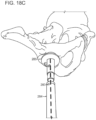
- the virtual surgical guide is configured to guide a proximal femoral bone cut based on a predetermined leg length.
- the virtual surgical guide is configured to guide a bone cut of a distal tibia or a talus in an ankle joint replacement and the at least one optical head mounted display is configured to align the virtual surgical guide based on a predetermined ankle alignment, wherein the predetermined ankle alignment includes a coronal plane implant component alignment, a sagittal plane implant component alignment, an axial plane component alignment, an implant component rotation or combinations thereof.
- the virtual surgical guide is configured to guide a bone cut of a proximal humerus in a shoulder joint replacement and the at least one optical head mounted display is configured to align the virtual surgical guide based on a predetermined humeral implant component alignment, wherein the humeral implant component alignment includes a coronal plane implant component alignment, a sagittal plane implant component alignment, an axial plane component alignment, an implant component, or combinations thereof.
- the predetermined position of the surgical guide is based on a pre-operative or intra-operative imaging study, one or more intra-operative measurements, intra-operative data or combinations thereof.
- aspects of the invention relate to a device comprising two or more optical head mounted displays for two or more users, wherein the device is configured to generate a virtual surgical guide, wherein the virtual surgical guide is a three-dimensional representation in digital format which corresponds to at least one of a portion of a physical surgical guide, a placement indicator of a physical surgical guide, or a combination thereof, wherein the optical head mounted display is configured to display the virtual surgical guide superimposed onto a physical joint based at least in part on coordinates of a predetermined position of the virtual surgical guide, and wherein the virtual surgical guide is configured for aligning the physical surgical guide or a saw blade to guide a bone cut of the joint.
- aspects of the invention relate to a device comprising at least one optical head mounted display and a virtual bone cut plane, wherein the virtual bone cut plane is configured to guide a bone cut of a joint, wherein the virtual bone cut plane corresponds to at least one portion of a bone cut plane, and wherein the optical head mounted display is configured to display the virtual bone cut plane superimposed onto a physical joint based at least in part on coordinates of a predetermined position of the virtual bone cut plane.
- the virtual bone cut plane is configured to guide a bone cut in a predetermined varus or valgus orientation or in a predetermined tibial slope or in a predetermined femoral flexion of an implant component or in a predetermined leg length.
- aspects of the invention relates to a method of preparing a joint for a prosthesis in a patient.
- the method comprises registering one or more optical head mounted displays worn by a surgeon or surgical assistant in a coordinate system, obtaining one or more intra-operative measurements from the patient's physical joint to determine one or more intra-operative coordinates, registering the one or more intra-operative coordinates from the patient's physical joint in the coordinate system, generating a virtual surgical guide, determining a predetermined position and/or orientation of the virtual surgical guide based on the one or more intra-operative measurements, displaying and superimposing the virtual surgical guide, using the one or more optical head mounted displays, onto the physical joint based at least in part on coordinates of the predetermined position of the virtual surgical guide, and aligning the physical surgical guide or a physical saw blade with the virtual surgical guide to guide a bone cut of the joint.
- the one or more optical head mounted displays are registered in a common coordinate system.
- the common coordinate system is a shared coordinate system.
- the virtual surgical guide is used to guide a bone cut in a knee replacement, hip replacement, shoulder joint replacement or ankle joint replacement.
- the predetermined position of the virtual surgical guide determines a tibial slope for implantation of one or more tibial implant components in a knee replacement. In some embodiments, the predetermined position of the virtual surgical guide determines an angle of varus or valgus correction for a femoral and/or a tibial component in a knee replacement.
- the virtual surgical guide corresponds to a physical distal femoral guide or cut block and the predetermined position of the virtual surgical guide determines a femoral component flexion.
- the virtual surgical guide corresponds to a physical anterior or posterior femoral surgical guide or cut block and the predetermined position of the virtual surgical guide determines a femoral component rotation.
- the virtual surgical guide corresponds to a physical chamfer femoral guide or cut block.
- the virtual surgical guide corresponds to a physical multi-cut femoral guide or cut block and the predetermined position of the virtual surgical guide determines one or more of an anterior cut, posterior cut, chamfer cuts and a femoral component rotation.
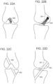
- the virtual surgical guide is used in a hip replacement and the predetermined position of the virtual surgical guide determines a leg length after implantation.
- the virtual surgical guide is a virtual plane for aligning the physical saw blade to guide the bone cut of the joint.
- the one or more intraoperative measurements include detecting one or more optical markers attached to the patient's joint, the operating room table, fixed structures in the operating room or combinations thereof.
- one or more cameras or image capture or video capture systems included in the optical head mounted display detect one or more optical markers including their coordinates (x, y, z) and at least one or more of a position, orientation, alignment, direction of movement or speed of movement of the one or more optical markers.
- registration of one or more of optical head mounted displays, surgical site, joint, spine, surgical instruments or implant components can be performed with use of spatial mapping techniques.
- registration of one or more of optical head mounted displays, surgical site, joint, spine, surgical instruments or implant components can be performed with use of depth sensors.
- the virtual surgical guide is used to guide a bone cut of a distal tibia or a talus in an ankle joint replacement and the one or more optical head mounted display is used to align the virtual surgical guide based on a predetermined tibial or talar implant component alignment, wherein the predetermined tibial or talar implant component alignment includes a coronal plane implant component alignment, a sagittal plane implant component alignment, an axial plane component alignment, an implant component rotation of an implant component or combinations thereof.
- the virtual surgical guide is used to guide a bone cut of a proximal humerus in a shoulder joint replacement and wherein the one or more optical head mounted display is used to align the virtual surgical guide based on a predetermined humeral implant component alignment, wherein the humeral implant component alignment includes a coronal plane implant component alignment, a sagittal plane implant component alignment, an axial plane component alignment, a humeral implant component rotation, or combinations thereof.
- aspects of the invention relate to a system comprising at least one optical head mounted display and a virtual library of implants, wherein the virtual library of implants comprises at least one virtual implant component, wherein the virtual implant component has at least one dimension that corresponds to a dimension of the implant component or has a dimension that is substantially identical to the dimension of the implant component, wherein the at least one optical head mounted display is configured to display the virtual implant component in substantial alignment with a tissue intended for placement of the implant component, wherein the placement of the virtual implant component is intended to achieve a predetermined implant component position and/or orientation.
- live data of the patient includes the surgical site, anatomy, anatomic structures or tissues and/or pathology, pathologic structures or tissues of the patient as seen by the surgeon's or viewer's eyes without information from virtual data, stereoscopic views of virtual data, or imaging studies.
- live data of the patient does not include internal or subsurface tissues or structures or hidden tissues or structures that can only be seen with assistance of a computer monitor or OHMD.
- real surgical instrument actual surgical instrument, physical surgical instrument and surgical instrument are used interchangeably throughout the application; the terms real surgical instrument, actual surgical instrument, physical surgical instrument and surgical instrument do not include virtual surgical instruments.
- the physical surgical instruments can be surgical instruments provided by manufacturers or vendors for spinal surgery, pedicle screw instrumentation, anterior spinal fusion, knee replacement, hip replacement, ankle replacement and/or shoulder replacement; physical surgical instruments can be, for example, cut blocks, pin guides, awls, reamers, impactors, broaches.
- Physical surgical instruments can be re-useable or disposable or combinations thereof.
- Physical surgical instruments can be patient specific.
- virtual surgical instrument does not include real surgical instrument, actual surgical instrument, physical surgical instrument and surgical instrument.
- real surgical tool actual surgical tool, physical surgical tool and surgical tool are used interchangeably throughout the application; the terms real surgical tool, actual surgical tool, physical surgical tool and surgical tool do not include virtual surgical tools.
- the physical surgical tools can be surgical tools provided by manufacturers or vendors.
- the physical surgical tools can be pins, drills, saw blades, retractors, frames for tissue distraction and other tools used for orthopedic, neurologic, urologic or cardiovascular surgery.
- the term virtual surgical tool does not include real surgical tool, actual surgical tool, physical surgical tool and surgical tool.
- real implant or implant component actual implant or implant component, physical implant or implant component and implant or implant component are used interchangeably throughout the application; the terms real implant or implant component, actual implant or implant component, physical implant or implant component and implant or implant component do not include virtual implant or implant components.
- the physical implants or implant components can be implants or implant components provided by manufacturers or vendors.
- the physical surgical implants can be a pedicle screw, a spinal rod, a spinal cage, a femoral or tibial component in a knee replacement, an acetabular cup or a femoral stem and head in hip replacement.
- virtual implant or implant component does not include real implant or implant component, actual implant or implant component, physical implant or implant component and implant or implant component.
- a first virtual instrument can be displayed on a computer monitor which is a representation of a physical instrument tracked with navigation markers, e.g. infrared or RF markers, and the position and/or orientation of the first virtual instrument can be compared with the position and/or orientation of a corresponding second virtual instrument generated in a virtual surgical plan.
- navigation markers e.g. infrared or RF markers
- aspects of the invention relates to devices, systems and methods for positioning a virtual path, virtual plane, virtual tool, virtual surgical instrument or virtual implant component in a mixed reality environment using a head mounted display device, optionally coupled to one or more processing units.
- a virtual surgical guide, tool, instrument or implant can be superimposed onto the physical joint, spine or surgical site. Further, the physical guide, tool, instrument or implant can be aligned with the virtual surgical guide, tool, instrument or implant displayed or projected by the OHMD.
- guidance in mixed reality environment does not need to use a plurality of virtual representations of the guide, tool, instrument or implant and does not need to compare the positions and/or orientations of the plurality of virtual representations of the virtual guide, tool, instrument or implant.
- the OHMD can display one or more of a virtual surgical tool, virtual surgical instrument including a virtual surgical guide or virtual cut block, virtual trial implant, virtual implant component, virtual implant or virtual device, predetermined start point, predetermined start position, predetermined start orientation or alignment, predetermined intermediate point(s), predetermined intermediate position(s), predetermined intermediate orientation or alignment, predetermined end point, predetermined end position, predetermined end orientation or alignment, predetermined path, predetermined plane, predetermined cut plane, predetermined contour or outline or cross-section or surface features or shape or projection, predetermined depth marker or depth gauge, predetermined angle or orientation or rotation marker, predetermined axis, e.g.
- Any of a position, location, orientation, alignment, direction, speed of movement, force applied of a surgical instrument or tool, virtual and/or physical can be predetermined using, for example, pre-operative imaging studies, pre-operative data, pre-operative measurements, intra-operative imaging studies, intra-operative data, and/or intra-operative measurements.
- Intra-operative measurements can include measurements for purposes of registration, e.g. of a joint, a spine, a surgical site, a bone, a cartilage, an OHMD, a surgical tool or instrument, a trial implant, an implant component or an implant.
- multiple coordinate systems can be used instead of a common or shared coordinate system.
- coordinate transfers can be applied from one coordinate system to another coordinate system, for example for registering the OHMD, live data of the patient including the surgical site, virtual instruments and/or virtual implants and physical instruments and physical implants.
- a pair of glasses is utilized.
- the glasses can include an optical head-mounted display.
- An optical head-mounted display can be a wearable display that has the capability of reflecting projected images as well as allowing the user to see through it.
- OHMD's can be used in order to practice the invention. These include curved mirror or curved combiner OHMD's as well as wave-guide or light-guide OHMD's.
- the OHMD's can optionally utilize diffraction optics, holographic optics, polarized optics, and reflective optics.
- OHMD's Traditional input devices that can be used with the OHMD's include, but are not limited to touchpad or buttons, smartphone controllers, speech recognition, and gesture recognition. Advanced interfaces are possible, e.g. a brain - computer interface.
- a computer or server or a workstation can transmit data to the OHMD.
- the data transmission can occur via cable, Bluetooth, WiFi, optical signals and any other method or mode of data transmission known in the art.
- the OHMD can display virtual data, e.g. virtual data of the patient, in uncompressed form or in compressed form. Virtual data of a patient can optionally be reduced in resolution when transmitted to the OHMD or when displayed by the OHMD.
- virtual data When virtual data are transmitted to the OHMD, they can be in compressed form during the transmission. The OHMD can then optionally decompress them so that uncompressed virtual data are being displayed by the OHMD.
- virtual data when transmitted to the OHMD, they can be of reduced resolution during the transmission, for example by increasing the slice thickness of image data prior to the transmission.
- the OHMD can then optionally increase the resolution, for example by re-interpolating to the original slice thickness of the image data or even thinner slices so that virtual data with resolution equal to or greater than the original virtual data or at least greater in resolution than the transmitted data are being displayed by the OHMD.
- the OHMD can transmit data back to a computer, a server or a workstation.
- data can include, but are not limited to:
- Radiofrequency tags used throughout the embodiments can be of active or passive kind with or without a battery.
- Exemplary optical head mounted displays include the ODG R-7, R-8 and R-8 smart glasses from ODG (Osterhout Group, San Francisco, CA), the NVIDIA 942 3-D vision wireless glasses (NVIDIA, Santa Clara, CA) and the Microsoft HoloLens (Microsoft, Redmond, Wl).
- the Microsoft HoloLens is manufactured by Microsoft. It is a pair of augmented reality smart glasses. Hololens can use the Windows 10 operating system.
- the front portion of the Hololens includes, among others, sensors, related hardware, several cameras and processors.
- the visor includes a pair of transparent combiner lenses, in which the projected images are displayed.
- the HoloLens can be adjusted for the interpupillary distance (IPD) using an integrated program that recognizes gestures.
- IPD interpupillary distance
- a pair of speakers is also integrated. The speakers do not exclude external sounds and allow the user to hear virtual sounds.
- a USB 2.0 micro-B receptacle is integrated.
- a 3.5 mm audio jack is also present.
- the HoloLens has an inertial measurement unit (IMU) with an accelerometer, gyroscope, and a magnetometer, four environment mapping sensors/cameras (two on each side), a depth camera with a 120° ⁇ 120° angle of view, a 2.4-megapixel photographic video camera, a four-microphone array, and an ambient light sensor.
- IMU inertial measurement unit
- Hololens has an Intel Cherry Trail SoC containing the CPU and GPU.
- HoloLens includes also a custom-made Microsoft Holographic Processing Unit (HPU).
- the SoC and the HPU each have 1GB LPDDR3 and share 8MB SRAM, with the SoC also controlling 64GB eMMC and running the Windows 10 operating system.
- the HPU processes and integrates data from the sensors, as well as handling tasks such as spatial mapping, gesture recognition, and voice and speech recognition.
- HoloLens includes a IEEE 802.11ac Wi-Fi and Bluetooth 4.1 Low Energy (LE) wireless connectivity.
- the headset uses Bluetooth LE and can connect to a Clicker, a finger-operating input device that can be used for selecting menus and functions.
- a number of applications are available for Microsoft Hololens, for example a catalogue of holograms, HoloStudio, a 3D modelling application by Microsoft with 3D print capability, Autodesk Maya 3D creation application' FreeForm, integrating HoloLens with the Autodesk Fusion 360 cloud-based 3D development application, and others.
- HoloLens utilizing the HPU can employ sensual and natural interface commands-voice, gesture, and gesture. Gaze commands, e.g. head-tracking, allows the user to bring application focus to whatever the user is perceiving. Any virtual application or button can be are selected using an air tap method, similar to clicking a virtual computer mouse. The tap can be held for a drag simulation to move an display. Voice commands can also be utilized.
- the HoloLens shell utilizes many components or concepts from the Windows desktop environment.
- a bloom gesture for opening the main menu is performed by opening one's hand, with the palm facing up and the fingers spread. Windows can be dragged to a particular position, locked and/or resized.
- Virtual windows or menus can be fixed at locations or physical objects. Virtual windows or menus can move with the user or can be fixed in relationship to the user. Or they can follow the user as he or she moves around.
- the Microsoft HoloLens App for Windows 10 PC's and Windows 10 Mobile devices can be used by developers to run apps and to view live stream from the HoloLens user's point of view, and to capture augmented reality photos and videos.
- the optical head mount display uses a computer graphics viewing pipeline that consists of the following steps to display 3D objects or 2D objects positioned in 3D space or other computer generated objects and models FIG. 16B :
- the different objects to be displayed by the OHMD computer graphics system are initially all defined in their own independent model coordinate system.
- spatial relationships between the different objects are defined, and each object is transformed from its own model coordinate system into a common global coordinate system. Different techniques that are described below can be applied for the registration process.
- the global coordinate system is defined by the environment.
- a process called spatial mapping described below, creates a computer representation of the environment that allows for merging and registration with the computer-generated objects, thus defining a spatial relationship between the computer-generated objects and the physical environment.
- This view projection step uses the viewpoint and view direction to define the transformations applied in this step.
- stereoscopic displays such as an OHMD
- two different view projections can be used, one for the left eye and the other one for the right eye.
- augmented reality OHMD's the position of the viewpoint and view direction relative to the physical environment can be known in order to correctly superimpose the computer-generated objects with the physical environment.
- the viewpoint and view direction change for example due to head movement, the view projections are updated so that the computer-generated display follows the new view.
- the present invention provides for methods of using the human eye including eye movements and lid movements as well as movements induced by the peri-orbital muscles for executing computer commands.
- the invention provides also for methods of executing computer commands by way of facial movements and movements of the head.
- facial movements and head movements can be advantageous in environments where an operator does not have his hands available to type on a keyboard or to execute commands on a touchpad or other hand - computer interface.
- Such situations include, but are not limited, to industrial applications including automotive and airplane manufacturing, chip manufacturing, medical or surgical procedures and many other potential applications.
- the optical head mount display can include an eye tracking system.
- Eye tracking systems can be utilized. The examples provided below are in no way thought to be limiting to the invention. Any eye tracking system known in the art now can be utilized.
- Eye movement can be divided into fixations and saccades - when the eye gaze pauses in a certain position, and when it moves to another position, respectively.
- the resulting series of fixations and saccades can be defined as a scan path.
- the central one or two degrees of the visual angle provide most of the visual information; the input from the periphery is less informative.
- the locations of fixations along a scan path show what information locations were processed during an eye tracking session, for example during a surgical procedure.
- Eye trackers can measure rotation or movement of the eye in several ways, for example via measurement of the movement of an object (for example, a form of contact lens) attached to the eye, optical tracking without direct contact to the eye, and measurement of electric potentials using electrodes placed around the eyes.
- an object for example, a form of contact lens
- an attachment to the eye can, for example, be a special contact lens with an embedded mirror or magnetic field sensor.
- the movement of the attachment can be measured with the assumption that it does not slip significantly as the eye rotates. Measurements with tight fitting contact lenses can provide very accurate measurements of eye movement.
- magnetic search coils can be utilized which allow measurement of eye movement in horizontal, vertical and torsion direction.
- non-contact, optical methods for measuring eye motion can be used.
- light optionally infrared
- the information can then be measured to extract eye rotation and/or movement from changes in reflections.
- Optical sensor or video-based eye trackers can use the corneal reflection (the so-called first Purkinje image) and the center of the pupil as features to track, optionally over time.
- a more sensitive type of eye tracker, the dual-Purkinje eye tracker uses reflections from the front of the cornea (first Purkinje image) and the back of the lens (fourth Purkinje image) as features to track.
- An even more sensitive method of tracking is to image features from inside the eye, such as the retinal blood vessels, and follow these features as the eye rotates and or moves.
- Optical methods particularly those based on optical sensors or video recording, can be used for gaze tracking.
- optical or video-based eye trackers can be used.
- a camera focuses on one or both eyes and tracks their movement as the viewer performs a function such as a surgical procedure.
- the eye-tracker can use the center of the pupil for tracking.
- Infrared or near-infrared non-collimated light can be utilized to create corneal reflections.
- the vector between the pupil center and the corneal reflections can be used to compute the point of regard on a surface or the gaze direction.
- a calibration procedure can be performed at the beginning of the eye tracking.
- Bright-pupil and dark-pupil eye tracking can be employed. Their difference is based on the location of the illumination source with respect to the optics. If the illumination is co-axial relative to the optical path, then the eye acts is retroreflective as the light reflects off the retina creating a bright pupil effect similar to a red eye. If the illumination source is offset from the optical path, then the pupil appears dark because the retroreflection from the retina is directed away from the optical sensor or camera.
- Bright-pupil tracking can have the benefit of greater iris/pupil contrast, allowing more robust eye tracking with all iris pigmentation. It can also reduce interference caused by eyelashes. It can allow for tracking in lighting conditions that include darkness and very bright lighting situations.
- the optical tracking method can include tracking movement of the eye including the pupil as described above.
- the optical tracking method can also include tracking of the movement of the eye lids and also periorbital and facial muscles.
- the eye-tracking apparatus is integrated in an optical head mounted display.
- head motion can be simultaneously tracked, for example using an a combination of accelerometers and gyroscopes forming an inertial measurement unit (see below).
- electric potentials can be measured with electrodes placed around the eyes.
- the eyes generate an electric potential field, which can also be detected if the eyes are closed.
- the electric potential field can be modelled to be generated by a dipole with the positive pole at the cornea and the negative pole at the retina. It can be measured by placing two electrodes on the skin around the eye. The electric potentials measured in this manner are called an electro-oculogram.
- a horizontal and a vertical can be identified.
- a posterior skull electrode a EOG component in radial direction can be measured. This is typically the average of the EOG channels referenced to the posterior skull electrode.
- the radial EOG channel can measure saccadic spike potentials originating from extra-ocular muscles at the onset of saccades.
- EOG can be limited for measuring slow eye movement and detecting gaze direction.
- EOG is, however, well suited for measuring rapid or saccadic eye movement associated with gaze shifts and for detecting blinks.
- EOG allows recording of eye movements even with eyes closed.
- the major disadvantage of EOG is its relatively poor gaze direction accuracy compared to an optical or video tracker.
- both methods, optical or video tracking and EOG can be combined in select embodiments of the invention.
- a sampling rate of 15, 20, 25, 30, 50, 60, 100, 120, 240, 250, 500, 1000 Hz or greater can be used. Any sampling frequency is possibly. In many embodiments, sampling rates greater than 30 Hz will be preferred.
- the location, orientation, and acceleration of the human head, portions of the human body, e.g. hands, arms, legs or feet, as well as portions of the patient's body, e.g. the patient's head or extremities, including the hip, knee, ankle, foot, shoulder, elbow, hand or wrist and any other body part, can, for example, be measured with a combination of gyroscopes and accelerometers. In select applications, magnetometers may also be used. Such measurement systems using any of these components can be defined as inertial measurement units (IMU).
- IMU inertial measurement units
- the term IMU relates to an electronic device that can measure and transmit information on a body's specific force, angular rate, and, optionally, the magnetic field surrounding the body, using a combination of accelerometers and gyroscopes, and, optionally, magnetometers.
- An IMU or components thereof can be coupled with or registered with a navigation system or a robot, for example by registering a body or portions of a body within a shared coordinate system.
- an IMU can be wireless, for example using WiFi networks or Bluetooth networks.
- Pairs of accelerometers extended over a region of space can be used to detect differences (gradients) in the proper accelerations of frames of references associated with those points.
- Single- and multi-axis models of accelerometer are available to detect magnitude and direction of the acceleration, as a vector quantity, and can be used to sense orientation (because direction of weight changes), coordinate acceleration (so long as it produces g-force or a change in g-force), vibration, shock.
- Micromachined accelerometers can be utilized in some embodiments to detect the position of the device or the operator's head.
- Piezoelectric, piezoresistive and capacitive devices can be used to convert the mechanical motion into an electrical signal.
- Piezoelectric accelerometers rely on piezoceramics or single crystals Piezoresistive accelerometers can also be utilized.
- Capacitive accelerometers typically use a silicon micro-machined sensing element.
- Accelerometers used in some of the embodiments can include small micro electro-mechanical systems (MEMS), consisting, for example, of little more than a cantilever beam with a proof mass.
- MEMS micro electro-mechanical systems
- the accelerometer can be integrated in the optical head mounted devices and both the outputs from the eye tracking system and the accelerometer(s) can be utilized for command execution.
- the following exemplary information can be captured about the operator and the patient and respective body parts: Speed, Velocity, Acceleration, Position in space, Positional change, Alignment, Orientation, and/or Direction of movement (e.g. through sequential measurements)
- Operator and / or patient body parts about which such information can be transmitted by the IMU include, but are not limited to: Head, Chest, Trunk, Shoulder, Elbow, Wrist, Hand, Fingers, Arm, Hip, Knee, Ankle, Foot, Toes, Leg, Inner organs, e.g. brain, heart, lungs, liver, spleen, bowel, bladder etc.
- IMU's can be placed on the OHMD, the operator and/or the patient and, optionally, these IMU's can be cross-referenced to each other within a single or multiple coordinate systems or, optionally, they can be cross-referenced in relationship to an OHMD, a second and third or more OHMD's, a navigation system or a robot and one or more coordinate systems used by such navigation system and / or robot.
- a navigation system can be used in conjunction with an OHMD without the use of an IMU.
- navigation markers including infrared markers, retroreflective markers, RF markers can be attached to an OHMD and, optionally, portions or segments of the patient or the patient's anatomy.
- the OHMD and the patient or the patient's anatomy can be cross-referenced in this manner or registered in one or more coordinate systems used by the navigation system and movements of the OHMD or the operator wearing the OHMD can be registered in relationship to the patient within these one or more coordinate systems.
- the virtual data and the live data of the patient and the OHMD are registered in the same coordinate system, e.g.
- any change in position of any of the OHMD in relationship to the patient measured in this fashion can be used to move virtual data of the patient in relationship to live data of the patient, so that the visual image of the virtual data of the patient and the live data of the patient seen through the OHDM are always aligned, irrespective of movement of the OHMD and/or the operator's head and/or the operator wearing the OHMD.
- multiple OHMD's are used, e.g. one for the primary surgeon and additional ones, e.g.
- the OHMD's worn by the other staff will also display the virtual representation(s) of the virtual data of the patient aligned with the corresponding live data of the patient seen through the OHMD, wherein the perspective of the virtual data that is with the patient and/or the surgical site for the location, position, and/or orientation of the viewer's eyes for each of the OHMD's used and each viewer.
- the IMU's, optical markers, RF markers, infrared markers and/or navigation markers placed on the operator and/or the patient as well as any spatial anchors can be registered in the same coordinate system as the primary OHMD and any additional OHMD's.
- the position, orientation, alignment, and change in position, orientation and alignment in relationship to the patient and/or the surgical site of each additional OHMD can be individually monitored thereby maintaining alignment and/or superimposition of corresponding structures in the live data of the patient and the virtual data of the patient for each additional OHMD irrespective of their position, orientation, and/or alignment in relationship to the patient and/or the surgical site.
- a system 10 for using multiple OHMD's 11, 12, 13, 14 for multiple viewer's e.g. a primary surgeon, second surgeon, surgical assistant(s) and/or nurses(s) is shown.
- the multiple OHMD's can be registered in a common coordinate system 15 using anatomic structures, anatomic landmarks, calibration phantoms, reference phantoms, optical markers, navigation markers, and/or spatial anchors, for example like the spatial anchors used by the Microsoft Hololens.
- Pre-operative data 16 of the patient can also be registered in the common coordinate system 15.
- Live data 18 of the patient for example from the surgical site, e.g.
- a spine optionally with minimally invasive access, a hip arthrotomy site, a knee arthrotomy site, a bone cut, an altered surface can be measured, for example using one or more IMU's, optical markers, navigation markers, image or video capture systems and/or spatial anchors.
- the live data 18 of the patient can be registered in the common coordinate system 15.
- Intra-operative imaging studies 20 can be registered in the common coordinate system 15.
- OR references, e.g. an OR table or room fixtures can be registered in the common coordinate system 15 using, for example, optical markers IMU's, navigation markers or spatial mapping 22.
- the pre-operative data 16 or live data 18 including intra-operative measurements or combinations thereof can be used to develop, generate or modify a virtual surgical plan 24.
- the virtual surgical plan 24 can be registered in the common coordinate system 15.
- the OHMD's 11, 12, 13, 14 can project digital holograms of the virtual data or virtual data into the view of the left eye using the view position and orientation of the left eye 26 and can project digital holograms of the virtual data or virtual data into the view of the right eye using the view position and orientation of the right eye 28 of each user, resulting in a shared digital holographic experience 30.
- the surgeon wearing OHMD 111 can execute commands 32, e.g. to display the next predetermined bone cut, e.g.
- OHMD's 11, 12, 13, 14 can trigger the OHMD's 11, 12, 13, 14 to project digital holograms of the next surgical step 34 superimposed onto and aligned with the surgical site in a predetermined position and/or orientation.
- Virtual data of the patient can be projected superimposed onto live data of the patient for each individual viewer by each individual OHMD for their respective view angle or perspective by registering live data of the patient, e.g. the surgical field, and virtual data of the patient as well as each OHMD in a common, shared coordinate system.
- live data of the patient e.g. the surgical field
- virtual data of the patient as well as each OHMD in a common, shared coordinate system.
- virtual data of the patient including aspects of a virtual surgical plan can remain superimposed and/or aligned with live data of the patient irrespective of the view angle or perspective of the viewer and alignment and/or superimposition can be maintained as the viewer moves his or her head or body.
- One subject of the present invention is to provide a novel user interface where the human eye including eye movements and lid movements including movements induced by the orbital and peri-orbital and select skull muscles are detected by the eye tracking system and are processed to execute predefined, actionable computer commands.
- Table 1 An exemplary list of eye movements and lid movements that can be detected by the system is provided in Table 1.
- Table 1 Exemplary list of eye movements and lid movements detected by the eye tracking softwa re ⁇ 1 blink ⁇ 2 blinks ⁇ 3 blinks ⁇ Fast blink, for example less than 0.5 seconds ⁇
- Slow blink for example more than 1.0 seconds ⁇ 2 or more blinks with fast time interval, e.g. less than 1 second ⁇ 2 or more blinks with long time interval, e.g. more than 2 seconds (typically chosen to be less than the natural time interval between eye blinks) ⁇ Blink left eye only ⁇ Blink right eye only ⁇ Blink left eye and right eye simultaneously ⁇ Blink left eye first, then within short time interval (e.g.
- blink right eye ⁇ Blink right eye first then within short time interval (e.g. less than 1 second), blink left eye ⁇ Blink left eye first, then within long time interval (e.g. more than 2 seconds), blink right eye ⁇ Blink right eye first, then within long time interval (e.g. more than 2 seconds), blink left eye ⁇ Rapid eye movement to left ⁇ Rapid eye movement to right ⁇ Rapid eye movement up ⁇ Rapid eye movement down ⁇ Widen eyes, hold for short time interval, e.g. less than 1 second ⁇ Widen eyes, hold for long time interval, e.g. more than 2 seconds ⁇ Close both eyes for 1 second etc. ⁇ Close both eyes for 2 seconds or more etc.
- commands can be computer commands that can direct or steer, for example, a surgical instrument or a robot.
- the invention provides also for methods of executing commands by way of facial movements and movements of the head.
- Table 2 An exemplary list of facial movements and head movements that can be detected by the system is provided in Table 2. (This list is only an example and by no way meant to be exhaustive; any number or combination of movements is possible).
- Table 2 Exemplary list of facial movements and head movements detected: ⁇ Move head fast to right and hold ⁇ Move head fast to left and hold ⁇ Move head fast down and hold ⁇ Move head fast down and hold ⁇ Move head fast to right and back ⁇ Move head fast to left and back ⁇ Move head fast down and back ⁇ Move head fast down and back ⁇ Move head fast down and back ⁇ Tilt head to left and hold ⁇ Tilt head to right and hold ⁇ Tilt head to left and back ⁇ Tilt head to right and back ⁇ Open mouth and hold ⁇ Open mouth and close ⁇ Twitch nose once ⁇ Twitch nose twice etc.
- Exemplary commands executed using eye movements, lid movements, facial movements and head movements are listed in Table 3.
- Table 3 Exemplary list of commands that can be executed by tracking eye movement, lid movement, facial movement and head movement (this list is only an example and by no way meant to be exhaustive; any number or combination of commands is possible; application specific commands can be executed in this manner as well).
- ⁇ Click ⁇ Point ⁇ Move pointer ⁇ Slow ⁇ Fast ⁇ Scroll e.g. through images ⁇ Fast scroll ⁇ Slow scroll ⁇ Scroll up ⁇ Scroll down ⁇ Scroll left ⁇ Scroll right ⁇ Drag ⁇ Swoosh ⁇ Register ⁇ Toggle 2D vs.
- eye movements, lid movements, facial movement, head movements alone or in combination can be used to signal numerical codes or sequences of numbers or sequences of machine operations.
- sequences of numbers can, for example, be used to execute certain machine operating sequences.
- head movement can be used to control a surgical instrument.
- the surgeon can use his or her hands in controlling the direction of a surgical instrument.
- the surgeon can move the head forward. This forward motion is captured by an IMU and translated into a forward movement of a robotic arm holding a surgical instrument along the direction of the surgical instrument.
- a backward movement of the head can be captured by the IMU and can be translated into a backward movement of the robotic arm holding a surgical instrument along the direction of the surgical instrument.
- eye movements, lid movements, facial movement, head movements alone or in combination can be used to signal Morse codes.
- the International Morse Code encodes the Latin alphabet using a small set of punctuation and procedural signals as standardized sequences of short and long signals called dots and dashes. Each character (letter or numeral) is represented by a unique sequence of dots and dashes. The duration of a dash is three times the duration of a dot. Each dot or dash is followed by a short silence, equal to the dot duration. The letters of a word are separated by a space equal to three dots (one dash), and the words are separated by a space equal to seven dots.
- Morse code can be executed using eye commands as follows; this is in no way meant to be limiting. Many different implementations are possible.
- a dot can be executed, for example, using a fast blink of both eyes (typically less than 1 sec), while a dash can be executed by closing the right eye only, for example for one second.
- the letter A in Morse code is a dot followed by a dash. With this encoding of Morse code, the letter A can be executed with a fast blink of both eyes (dot), followed by closing the right eye only for one second (dash).
- the letter B (dash, three dots), can be executed by closing the right eye only for one second (dash) followed by three fast blinks of both eyes (three dots) and so forth.
- Letters can be separated, for example, by maintaining a two second or longer break between eye commands. Alternatively, in another example, letters can be separate by closing only the left eye for about one second.
- Binary codes can optionally also be executed using eye commands. For example, a fast blink of both eyes can represent the number 0, while closing the right eye only for about one second can represent the number 1. Alternatively, closing the right eye only for about one second can represent the number 0, while closing the left eye only for about one second can represent the number 1. Many different types of encoding are possible. Other numericals can also be executed using, for example, some of the eye, lid, facial and/or head movements shown in Tables 1 and 2.
- eye, lid, facial and head movement commands can be paired or used in conjunction with voice commands, hand commands, gesture commands, keyboard commands, track pad commands, mouse commands, graphical user interface commands and any other command input device known in the art.
- the OHMD can optionally also include one or more touch sensitive sensors.
- eye commands add benefit of being able to navigate a screen or execute commands while maintaining privacy or confidentiality related to the commands.
- eye commands can be utilized to access a patient's medical records or to order lab tests or other diagnostic tests without bystanders being aware that these records are being reviewed or that these tests are being ordered.
- the wearer of an optical head mounted display can utilize eye commands to turn on a video or audio recording function or transmission to a remote site or remote conference room without disclosing that the recording function has been activated. This is quite different from manual activation of a recording function, where the user would, for example, push a button or a touch sensitive sensor on the optical head mounted display in order to activate the recording function.
- a user can utilize eye movements, facial movements or head movements to direct digital camera for taking photographs or videos.
- Commands can include but are not limited to zoom in, zoom out, move region of interest left, right up, down, take photo, take sequence of photos, turn on/off flash start video recording, stop video recording, change resolution, increase resolution, decrease resolution.
- Any other camera command known in the art can be executed in this manner using eye movement, facial movement or head movement based commands.
- eye movement facial movement or head movement based commands.
- head movement By utilizing one or more commands of this type, the user can maintain privacy while obtaining image information about the surrounding environment.
- Eye commands can be useful to surgeons or operating room personnel to execute commands without use of the hands and thereby maintaining sterility.
- an operator such as a surgeon may look through an OHMD observing physical data or information on a patient, e.g. a surgical site or changes induced on a surgical site, while pre-existing data of the patient are superimposed onto the physical visual representation of the live patient.
- the pre-existing data of the patient can be an imaging test or imaging data or other types of data including metabolic information or functional information.
- the pre-existing data of the patient including one or more imaging tests or other types of data including metabolic or functional information can be obtained at a time different from the time of the surgical procedure.
- the pre-existing data of the patient can be obtained one, two, three or more days or weeks prior to the surgical procedure.
- the pre-existing data of the patient including one or more imaging tests or other types of data including metabolic or functional information are typically obtained with the patient or the surgical site being located in a different location or a different object coordinate system in the pre-existing data when compared to the location or the object coordinate system of the live patient or the surgical site in the live patient.
- pre-existing data of the patient or the surgical site are typically located in a first object coordinate system and live data of the patient or the surgical site are typically located in a second object coordinate systems; the first and the second object coordinate system are typically different from each other.
- the first object coordinate system with the pre-existing data needs to be registered with the second object coordinate system with the live data of the patient including, for example, the live surgical site.
- Various embodiments of this invention can be practiced in one, two, three or more dimensions.
- the following is an exemplary list of potential dimensions, views, projections, angles, or reconstructions that can be applied; this list is not exhaustive, but only exemplary.
- Any skilled in the art can identify additional dimensions, views, projections, angles or reconstructions that can be used in practicing the invention.
- Exemplary dimensions are listed in Table 4.
- TABLE 4 Exemplary list of potential dimensions, views, projections, angles, or reconstructions that can be displayed using virtual representations with optical head mounted display(s), optionally stereoscopic 1 st dimension: superoinferior, e.g. patient physical data 2 nd dimension: mediolateral, e.g.
- patient physical data 3 rd dimension anteroposterior, e.g. patient physical data 4 th - 6 th dimension: head motion (and with it motion of glasses / OHMD) in 1, 2 or 3 dimensions 7 th - 9 th dimension: instrument motion in 1, 2 or 3 dimensions, e.g. in relationship to surgical field, organ or head including head motion 10 th - 13 th dimension: arm or hand motion in 1, 2 or 3 dimensions, e.g. in relationship to surgical field, organ or head including head motion 14 th - 16 th dimension: virtual 3D data of patient, obtained, for example from a scan or intraoperative measurements 17 th - 19 th dimension: vascular flow; in 1, 2 or 3 dimensions, e.g.
- th - 22 nd dimension temperature map (including changes induced by cryo- or hyperthermia), thermal imaging, in 1, 2 or 3 dimensions, e.g. in relationship to surgical field 25 th -28 th dimension: metabolic map (e.g. using MRS, PET-CT, SPECT-CT), in 1, 2 or 3 dimensions, e.g. in relationship to surgical field 29 th -32 nd dimension: functional map (e.g. using fMRI, PET-CT, SPECT-CT, PET, kinematic imaging), in 1, 2 or 3 dimensions, e.g. in relationship to surgical field or patient
- Any oblique planes are possible. Any perspective projections are possible. Any oblique angles are possible. Any curved planes are possible. Any curved perspective projections are possible. Any combination of 1D, 2D, and 3D data between the different types of data is possible. Registering Virtual Data with Live Data Seen Through Optical Head Mounted Display
- virtual data of a patient can be superimposed onto live data seen through the optical head mounted display.
- the virtual data can be raw data in unprocessed form, e.g. preoperative images of a patient, or they can be processed data, e.g. filtered data or segmented data.
- image segmentation can be desirable.
- Any known algorithm in the art can be used for this purpose, for example thresholding, seed point techniques, live wire, deformable models, statistical models, active shape models, level set methods, marching cubes algorithms, artificial neural networks, deep learning techniques, or combinations thereof and the like.
- Many of these algorithms are available is part of open-source or commercial libraries, for instance the Insight Segmentation and Registration Toolkit (ITK), the Open Source Computer Vision Library OpenCV, G'MIC (GREYC's Magic for Image Computing), Caffe, or MATLAB (MathWorks, Natick, Mass.).
- IK Insight Segmentation and Registration Toolkit
- G'MIC GREYC's Magic for Image Computing
- Caffe or MATLAB (MathWorks, Natick, Mass.).
- An optional pre-operative imaging study 40 can be obtained.
- An optional intra-operative imaging study 41 can be obtained.
- the pre-operative 40 or intra-operative 41 imaging study can be segmented 42, extracting, for example, surfaces, volumes or key features.
- An optional 3D reconstruction or 3D rendering 43 can be generated.
- the pre-operative 40 or intra-operative 41 imaging study and any 3D reconstruction or 3D rendering 43 can be registered in a common coordinate system 44.
- the pre-operative 40 or intra-operative 41 imaging study and any 3D reconstruction or 3D rendering 43 can be used for generating a virtual surgical plan 45.
- the virtual surgical plan 45 can be registered in the common coordinate system 44.
- the surgical site 46 can be registered in the common coordinate system 44.
- Intra-operative measurements 47 can be obtained and can be used for generating a virtual surgical plan 45.
- An optical head mounted display 48 can project or display digital holograms of virtual data or virtual data 49 superimposed onto and aligned with the surgical site.
- the OHMD 48 is configured to use a built in camera or image capture or video capture system 50 to optionally detect and/or measure the position and/or orientation and/or alignment of one or more optical markers 51, which can be used for the coordinate measurements 52, which can be part of the intra-operative measurements 47.
- Registration of virtual data with live data can be performed using a variety of techniques know in the art. These include, but are not limited to, surface registration algorithms such as the Iterative Closest Point algorithm, statistical models, Active Shape Models, mutual information-based or other volume registration algorithms, object recognition, pattern recognition or computer vision techniques, deep learning or other artificial intelligence methods.
- the processed data can, for example, consist of mesh data, parametric surface data, point cloud data, volume data or a combination thereof.
- API's such as the Insight Segmentation and Registration Toolkit (ITK), the open-source computer vision library OpenCV, Elastix, Plastimatch, or the Medical Image Registration Toolkit (MIRTK).
- segmented data or raw data can be superimposed on the patient's live data seen through the optical head mounted display.
- This superimposition can occur in unregistered form, i.e. the patient's virtual data may not be aligned with the live data seen through the optical head mounted display.
- the operator who is wearing the OHMD may move his/her head in a direction of orientation that will superimpose corresponding features of virtual data and live patient data.
- the surgeon or operator can also move and reorient the virtual data using other means, e.g. a trackball or a virtual display interface displayed in the OHMD, unrelated to the surgeon / operator head movement.
- the operator can adjust the magnification of the live data so that the size, shape, length, thickness of certain features of the virtual data matches that of the live data for a given distance to the object / patient.
- the surgeon may visually in live data look at the exposed gyri and sulci of the patient's brain.
- the OHMD can display a virtual 3D model of the gyri and sulci of the patient.
- the surgeon can optionally adjust the magnification of the 3D model so that the model will match the size or width or the length of the corresponding gyri and sulci in the live data.
- the surgeon can optionally adjust the transparency or opacity of the virtual data displayed in the OHMD.
- live data transmitted through the OHMD can be 1 : 10, 1 : 9, 1 : 8, 1 : 5, 1 : 2, 1 : 1, 2 : 1, 3 : 1, 5 : 1, 8 : 1, 10 : 1, as well as fractions or multiples thereof. Any combination of transparency or opacity of virtual data and live data is possible. The surgeon can move his/her head in a direction or orientation that will superimpose virtual features, e.g. the patient's gyri and sulci, with the live patient data.
- the surgeon can optionally register the virtual data with the live data. This registration can be as simple as described here, e.g. a visual confirmation from the surgeon that virtual and live data are substantially matching or substantially superimposed.
- the surgeon can optionally reference the virtual data and / or the coordinate system of the virtual data in 2, 3 or more dimensions with the live data and / or the coordinate system of the live data.
- the surgeon can move his / her head into any desired position or orientation, for example for viewing the patient's brain or a lesion and adjacent, e.g. sensitive, anatomy from different view angles.
- the IMU of the OHMD will register the head movement, the direction of the head movement, the new head position and head orientation.
- the change in location and orientation of the surgeon's head can be simultaneously or, if desired, non-simultaneously applied to the virtual data which can now be superimposed with the resultant new position and orientation in relationship to the live data.
- the change in position and the increase in distance from the target anatomy can be measured by the IMU.
- a magnification or minification factor can be applied to the virtual data so that the size, shape and dimensions of the virtual data will, in some embodiments, be close to or match the size, shape and dimensions of the live data, irrespective of the distance, location and orientation of the surgeon's head.
- the OHMD can be optionally placed in a fixed position, e.g. mounted on a stand or on a tripod. While the OHMD is placed in the fixed position, live data can be viewed by the surgeon and they can be, optionally recorded with a camera and/or displayed on a monitor. Virtual data can then be superimposed and the matching and registration of virtual data and live data can be performed. At this point, the surgeon or an operator can remove OHMD from the fixed position and the surgeon can wear the OHMD during the surgical procedure.
- the virtual data can optionally be displayed using a different color, e.g. red, green, yellow etc.
- a different color e.g. red, green, yellow etc.
- these features can be the sulci of the patient's brain (e.g. with a black line or black or lines with other colors), with no visualization of the gyri that these sulci border.
- a lesion e.g. a tumor such as, in the example of the brain, glioblastoma
- combinations of virtual data of normal tissue and pathologic tissue can be displayed.
- the virtual data can be registered with the live data seen through the optical head mounted display.
- the registration can occur using any method known in the art for registering or cross-referencing virtual and live data, in 2, 3, or more dimensions.
- the registration of the virtual data and the live data will be maintained through the surgical procedure. In some embodiments, the registration of the virtual data and the live data will be maintained during select portions of the surgical procedure or the surgical plan, which can be or can include a virtual, e.g. a preoperatively generated, surgical plan.
- the superimposition of the virtual data and the live data by the OHMD occurs simultaneously. In some embodiments, the superimposition of the virtual data and the live data by the OHMD is not simultaneous. For example, the virtual data can be superimposed intermittently.
- Virtual data can be transparent, translucent or opaque. If virtual data are opaque, they may be displayed intermittently so that the operator or surgeon can see how they project in relationship to the live data of the patient.
- Any of the foregoing virtual data can be displayed in two dimensions or three dimensions. Multi-dimensional displays as outlined in other sections of the specification are possible.
- the patient's normal tissue e.g. normal brain tissue
- the patient's abnormal tissue e.g. a stroke, a hemorrhage or a tumor
- the patient's abnormal tissue e.g. a stroke, a hemorrhage or a tumor
- the patient's abnormal tissue e.g. a stroke, a hemorrhage or a tumor
- the patient's abnormal tissue can be displayed in three dimensions.
- Any combination of 2D, 3D, and mult-dimensional images is possible for display by the OHMD; any combination of 2D, 3D, and multi-dimensional images can be superimposed on live patient data by the OHMD.
- the virtual 2D, 3D, and multi-dimensional data can be generated or acquired by different data acquisition technologies, e.g. different imaging tests etc.
- virtual data can be locked in relationship to the surgeon or operator or in relationship to the patient or a certain target anatomy within a patient. This means even if the surgeon moves his or her head or the body or parts of the patient's anatomy are being moved, the virtual data will not move in the OHMD display.
- the OHMD can display a virtual image of a target tissue or adjacent tissue.
- the virtual image of the target tissue or adjacent tissue can be, for example, an image through a tumor or other type of pathologic tissue.
- the virtual data will not move, but are being displayed within the same location.
- virtual data can move in relationship to the surgeon or operator or in relationship to the patient or a certain target anatomy within a patient. This means if the surgeon moves his or her head or the body or parts of the patient's anatomy are being moved, the virtual data will move in the OHMD display. For example, once registration has occurred, the OHMD can display a virtual image of a target tissue or adjacent tissue.
- the virtual image of the target tissue or adjacent tissue can be, for example, an image through a tumor or other type of pathologic tissue.
- the virtual data will move and change location and orientation the same way how the surgeon moves his / her head or body, typically reflecting the change in perspective or view angle that the surgeon obtained by moving his or her head or body.
- the moving of the virtual data can be at greater virtual distance or greater angle or lesser virtual distance or lesser angle than the movement of the surgeon's head or body.
- the moving or reorienting of virtual data to follow for example, the surgeon's head movements or body movements or operating arm or hand movements, or the movements of the patient or certain body parts of the patient can be accomplished, for example, by monitoring the movement and change in location and/or orientation of the surgeon's head using the IMU of the OHMD.
- optical or RF tracker's or other tracking devices known in the art can be applied to the OHMD and/or the patient including select body parts or target tissues of the patient, e.g. the patient's knee.
- the spatial location of the optical or RF trackers can be recorded, for example for a starting pose or position or location. Movement of the trackers, e.g. induced by movement of the surgeon's head or body or by movement of at least a part of the patient, can then be tracked using the navigation system.
- the information on positional change, orientational change or movement direction of the surgeon's head or the patient or both can then be used to update the virtual data, or the display of the virtual data in the OHMD, or both correspondingly. In this manner, the virtual data and the live data can be superimposed by the OHMD, typically in an accurate manner.
- positional, orientational, directional data and the like generated by the IMU can be used in conjunction with such data generated by a surgical navigation system.
- a combination of data can be beneficial for more accurate measurement of changes in position or orientation of the surgeon's head, body, operating arm, hand, or the patient.
- the OHMD can display a 2D virtual image of the patient.
- the image can be a transmission type image, e.g. an x-ray or CT scout scan.
- the image can be a cross-sectional image of select anatomy of the patient.
- the image can be an original image or a reformatted, reconstructed or segmented or partially segmented image of the patient.
- a surgeon will look through the OHMD at the patient's live data, e.g. the exposed brain surface with the patient's gyri and sulci.
- the surgeon can register virtual data of the patient, e.g. an MRI scan of the patient's brain, relative to the patient's live data. Registration can occur in 2, 3 or more dimensions. Registration of virtual data in relationship to live data can include registration of different types of virtual data, e.g. different types of normal or diseased tissue, different imaging modalities used, different dimensions used for different types of normal or diseased tissue etc.
- More than one 2D scan plane can be displayed simultaneously. These 2D scan planes can be parallel or non-parallel, orthogonal or non-orthogonal at variable angles.
- a surgeon or operator may optionally scroll through a set of consecutive or non-consecutive virtual 2D image data as well as 3D image data which are being superimposed onto the patient's live data, typically live data from the same anatomic region, e.g. a brain, a spine, a hip, a knee etc.
- the scrolling can be directed through any type of user interface, known in the art.
- a surgeon can use a virtual interface projected by the OHMD where he or she can move a virtual arrow up or down or left or right to scroll the images backward or forward or, for example, to rotate the images or to display them in different multiplanar angles or to change the view angle or projection angle.
- the surgeon can scroll through the virtual image data or move virtual image data by moving his head back and forth, e.g. for scrolling backward or forward in a virtual image volume.
- the surgeon can move his or her head left or right for example, to rotate the images or to display them in different multiplanar angles or to change the view angle or projection angle of a 3D image.
- the surgeon can scroll through the virtual image data by moving his or her hand or finger or any other body part back and forth, e.g. for scrolling backward or forward in a virtual image volume.
- the surgeon can move his or her hand or finger or any other body part back and forth left or right for example, to rotate the images or to display them in different multiplanar angles or to change the view angle or projection angle.
- the surgeon can move his or her hand or finger in a spinning or rotating movement to spin or rotate the virtual data. Any combination of head or hand or eye and other body signals can be used for changing the display of the virtual data.
- these display changes of the virtual data can be executed in the OHMD using the same location, position, orientation, angular, direction and movement related changes that are made by the surgeon's body part used to trigger the change in display.
- any one of location, position, orientation, angular, direction and movement related changes of the virtual data can be executed using a magnification factor or a minification factor in relationship to the changes in location, position, orientation, angular, direction and movement of the surgeon's body part.
- magnification or minification factors can be linear or non-linear, e.g. exponential or logarithmic.
- the further the surgeon's body part controlling the movement of the virtual data in the OHMD display moves away from its original position, the greater the induced change on the movement of the virtual data in the OHMD. In some embodiments, the further the surgeon's body part controlling the movement of the virtual data in the OHMD display moves away from its original position, the smaller the induced change on the movement of the virtual data in the OHMD.
- the OHMD can display a 3D virtual image of the patient.
- a 3D representation of the patient can include a 3D display of different types of anatomy, for example in an area of intended surgery or a surgical site.
- a 3D reconstruction of image data or other data of the patient can be generated preoperatively, intraoperatively and/or postoperatively.
- a virtual 3D representation can include an entire anatomic area or select tissues or select tissues of an anatomic area. Different tissues can be virtually displayed by the OHMD in 3D using, for example, different colors. Normal tissue(s) and pathologic tissue(s) can be displayed in this manner.
- Normal tissue can, for example, include brain tissue, heart tissue, lung tissue, liver tissue, vascular structures, bone, cartilage, spinal tissue, intervertebral disks, nerve roots. Any tissue can be visualized virtually by the OHMD.
- virtual data of a patient displayed by an OHMD and live data of a patient seen through an OHMD are spatially registered in relationship to each other, for example in a common coordinate system, for example with one or more optical OHMD's in the same common coordinate system.
- Virtual and physical surgical instruments and implant components can also be registered in the common coordinate system. Spatial co-registration can have the benefit that the simultaneous display of virtual and live data of the patient is not affected or less affected when the surgeon moves his or her head or body, when the OHMD moves or when the patient moves.
- the view perspective of the live data of the patient seen by the surgeon's eyes through the OHMD e.g.
- the live surgical field can stay the same as the view perspective of the virtual data of the patient seen by the surgeon's eyes through the display of the OHMD unit, e.g. the virtual surgical field, virtual surgical plane, virtual paths, virtual cut paths or planes, projected into the surgeon's eyes, even as the surgeon moves his or her head or body.
- the surgeon does not need to re-think or adjust his hand eye coordination since live data of the patient seen through the surgeon's eye and virtual data of the patient seen through the OHMD display are superimposed, which is fundamentally different from other approaches such as surgical navigation which employ a separate computer monitor in the OR with a view angle for the surgeon that is different than his or her view angle for the live data of the patient and the surgical field.
- a first virtual instrument can be displayed on a computer monitor which is a representation of a physical instrument tracked with navigation markers, e.g. infrared or RF markers, and the position and/or orientation of the first virtual instrument can be compared with the position and/or orientation of a corresponding second virtual instrument generated in a virtual surgical plan.
- navigation markers e.g. infrared or RF markers
- a virtual surgical guide, tool, instrument or implant can be superimposed onto the joint, spine or surgical site. Further, the physical guide, tool, instrument or implant can be aligned with the 2D or 3D representation of the virtual surgical guide, tool, instrument or implant.
- guidance in mixed reality environment does not need to use a plurality of virtual representations of the guide, tool, instrument or implant and does not need to compare the positions and/or orientations of the plurality of virtual representations of the virtual guide, tool, instrument or implant.
- virtual data can move in relationship to the surgeon or operator or in relationship to the patient or a certain target anatomy within a patient. This means if the surgeon moves his or her head or the body or parts of the patient's anatomy are being moved, the virtual data will move in the OHMD display. For example, once registration of the OHMD, the virtual data of the patient and the live data of the patient in a common coordinate system has occurred, the OHMD can display a virtual image of a target tissue or adjacent tissue.
- the virtual image of the target tissue or adjacent tissue can be, for example, an image of or through a tumor or other type of pathologic tissue or a spine or a spinal pedicle.
- the virtual data will move and change location and orientation the same way how the surgeon moves his / her head or body, typically reflecting the change in perspective or view angle that the surgeon obtained by moving his or her head or body.
- the virtual data can include a 3D representation of a surgical tool or instrument such as a needle for kyphoplasty or vertebroplasty, where the virtual representation of the needle shows its intended location, orientation or path in relationship to the spine and/or a pedicle.
- the virtual data can also include a medical device, such as a pedicle screw, wherein the virtual data of the pedicle screw shows its intended location, orientation or path in relationship to the spine, and/or a pedicle, and/or a vertebral body.
- registration is performed with at least three or more points that can be superimposed or fused into a common object coordinate system for virtual data and live data.
- Registration can also be performed using a surface or a 3D shape of an anatomic structure present in both virtual data and live data of the patient.
- the virtual surface can be moved until it substantially matches the live surface of the patient or the virtual shape can be moved until it substantially matches the live shape of the patient.
- Registration of virtual data of a patient and live data of a patient can be achieved using different means.
- the following is by no means meant to by limiting of the invention, but is only exemplary in nature.
- Registration of virtual and live data of the patient can be performed if the virtual data, e.g. imaging data of the patient, are acquired with the patient located in a first object coordinate system and the live data, e.g. during surgery, are observed or acquired with the patient located in a second object coordinate system, wherein the first and the second object coordinate system can be connected by direct, e.g. physical, or indirect, e.g. non-physical, means.
- a direct connection of the first and second object coordinate system can be, for example, a physical connection between the first and second object coordinate system.
- the patient can be moved from the first to the second object coordinate system along the length of a tape measure. Or the patient can be scanned inside a scanner, e.g.
- the scanner table can be subsequently moved out of the scanner for performing a surgical procedure with the patient still located on the scanner table.
- the scanner table can be a form of physical connection between the first and the second object coordinate system and the length of the table movement between the scan position and the outside the scanner position (for the live data, e.g. the surgical procedure) can define the coordinate transformation from the first to the second object coordinate system.
- An indirect connection between the first (virtual data) and second (live data) object can be established if the patient is moved between the acquiring the virtual data, e.g. using an imaging test, and the live data, e.g. while performing a surgical procedure, along a defined path, wherein the direction(s) and angle(s) of the path are known so that the first and the second object coordinate system can be cross-referenced and an object coordinate transfer can be applied using the known information of the defined path and virtual data of the patient, live data of the patient and the OHMD can be registered in a common coordinate system. Virtual and physical surgical instruments and implant components can also be registered in the common coordinate system.
- Registration of virtual patient data and live patient data is also possible without directly or indirectly connected object coordinate systems using other means and methods as will be explained in the following paragraphs and columns, for example when the patient performed one or more movements of unknown direction, length or magnitude.
- Combinations of all different registration methods described in the specification are possible, e.g. for switching registration methods during a procedure or for simultaneously using multiple registration methods, e.g. for enhancing the accuracy of the registration.
- Live data e.g. live data of the patient, the position and/or orientation of a physical instrument, the position and/or orientation of an implant component, the position and/or orientation of one or more OHMD's
- Live data can be acquired or registered, for example, using a spatial mapping process.
- This process creates a three-dimensional mesh describing the surfaces of one or more objects or environmental structures using, for example and without limitation, a depth sensor, laser scanner, structured light sensor, time of flight sensor, infrared sensor, or tracked probe.
- These devices can generate 3D surface data by collecting, for example, 3D coordinate information or information on the distance from the sensor of one or more surface points on the one or more objects or environmental structures.
- the 3D surface points can then be connected to 3D surface meshes, resulting in a three-dimensional surface representation of the live data.
- the surface mesh can then be merged with the virtual data using any of the registration techniques described in the specification.
- the live data can be static, or preferably, it can be continuously updated with additional information to incorporate changes in the position or surface of the one or more objects or environmental structures.
- the additional information can, for example be acquired by a depth sensor, laser scanner, structured light sensor, time of flight sensor, infrared sensor, or tracked probe.
- mapping data For initial spatial mapping and updating of mapping data, commonly available software code libraries can be used. For example, this functionality can be provided by the Microsoft HoloToolkit or the Google Project Tango platform. Various techniques have been described for spatial mapping and tracking including those described in US9,582,717 , which is expressly incorporated by reference herein.
- a surgeon or operator can visually align or match virtual patient data with live patient data.
- Such visually aligning or matching of virtual patient data and live patient data can, for example, be performed by moving the OHMD, for example via movement of the head of the operator who is wearing the OHMD.
- the virtual patient data can be displayed in a fixed manner, not changing perspective as the operator moves the OHMD.
- the operator will move the OHMD until the live patient data are aligned or superimposed onto the fixed projection of the virtual patient data.
- the surgeon can execute a registration command, for example via a voice command or a keyboard command.
- the virtual patient data and the live patient data are now registered.
- the virtual patient data will move corresponding to the movement of the OHMD, for example as measured via the movement of an integrated IMU, image and field of view tracking, e.g. using anchor points in an image or field of view using an image and/or video capture system, and/or an attached navigation system with optical or RF or other trackers, which can be attached to the patient, the surgical site, a bone or any other tissue of the patient, the surgeon, the surgeon's arm, the surgeon's head or an OHDM worn by the surgeon.
- an integrated IMU image and field of view tracking
- an attached navigation system with optical or RF or other trackers which can be attached to the patient, the surgical site, a bone or any other tissue of the patient, the surgeon, the surgeon's arm, the surgeon's head or an OHDM worn by the surgeon.
- the surgeon can execute a command indicating successful registration.
- the registration can include changes in at least one of position, orientation, and magnification of the virtual data and the live data in order to achieve the alignment or match.
- Magnification applied to the virtual data can be an indication of the distance from the OHMD or the surgeon's head to the matched tissue.
- the estimated distance between the OHMD and the target tissue or the skin surface or other reference tissue can be confirmed with an optional physical measurement of the distance, in particular if the OHMD is, for example, in a fixed position, e.g. on a stand or tripod, which may be used optionally during the initial registration.
- the surgeon command can register, for example, the virtual patient data and the live patient data or images and the OHMD in the same common coordinate system. Virtual and physical surgical instruments and implant components can also be registered in the common coordinate system.
- the visual anatomic data can be, for example, gyri of the brain or osteophytes or bone spurs or pathologic bone deformations or tumor nodes or nodules, e.g. on the surface of a liver or a brain.
- the registration of virtual patient data and live patient data using the methods described herein can be repeated after one or more surgical steps have been performed.
- the surgically altered tissue or tissue surface or tissue contour or shape e.g. shape of a bone after milling or reaming, or tissue perimeter, e.g. perimeter of a bone cut, or tissue volume or other tissue features in the live patient
- tissue perimeter e.g. perimeter of a bone cut, or tissue volume or other tissue features in the live patient
- tissue features in the live patient can be matched to, superimposed onto and/or registered with the surgically altered tissue or tissue surface or tissue contour or tissue perimeter or tissue volume or other tissue features in the virtual data of the patient, e.g.
- FIG. 3 illustrates an example of registering a digital hologram or virtual data for an initial surgical step, performing the surgical step and re-registering one or more holograms for subsequent surgical steps.
- An optical head mounted display can project or display a digital hologram of virtual data or virtual data of the patient 55.
- the digital hologram can optionally be fixed to the OHMD so that it will move with the movement of the OHMD 56.
- the operator can move the OHMD until digital hologram of the virtual data or virtual data of the patient is superimposed and aligned with the live data of the patient, e.g. the surgical site 57.
- the digital hologram of the virtual data or virtual data can then be registered using the same or similar coordinates as those of the live data with which the digital hologram is superimposed 58.
- the surgeon can then perform one or more predetermined surgical steps, e.g. bone cuts 59.
- a digital hologram of the virtual data or virtual data can optionally be registered or re-registered after the surgical alteration with the live data 60.
- the digital hologram of the virtual data or virtual data after the surgical alteration can optionally be displayed by the OHMD 61.
- the digital hologram of the virtual data or virtual data after the surgical alteration can optionally be fixed relative to the OHMD so that it will move with the movement of the OHMD 62.
- the operator can move the OHMD until digital hologram of the virtual data or virtual data of the patient after the surgical alteration is superimposed and aligned with the live data of the patient after the surgical alteration 63.
- the digital hologram of the virtual data or virtual data can then be registered using the same or similar coordinates as those of the live data after the surgical alteration with which the digital hologram is superimposed 64.
- the surgeon can then perform one or more predetermined subsequent surgical steps, e.g. bone cuts, milling or drilling 65.
- the preceding steps can optionally be repeated until the surgical procedures is completed 66.
- a virtual surgical plan 67 can be utilized.
- the native anatomy of the patient including after a first surgical alteration can be displayed by the OHMD 68.
- the OHMD can optionally display digital holograms of subsequent surgical steps 69.
- the patient can be placed on the operating table.
- cleaning or sterilization fluid can be applied to the shaved skull, for example using betadine.
- the OHMD can be placed over the patient, either on a tripod or worn by the operator, for example with the head of the patient turned sideways over the live patient's ear and lateral skull.
- the OHMD will be placed over an area of the live patient that includes the virtual data of the patient to be displayed.
- Virtual data of the patient can be displayed in the OHMD.
- the virtual data of the patient can include, for example, a visualization of the patient's skin or other data, e.g. the patient's ear or nose, for example derived from preoperative MRI data.
- the virtual data of the patient's skin or other structures, e.g. the patient's ear or nose can be displayed simultaneous with the live patient data.
- the virtual data of the patient can then be moved, re-oriented, re-aligned and, optionally, magnified or minified until a satisfactory alignment, match or superimposition has been achieved.
- the OHMD can be moved also during this process, e.g. to achieve a satisfactory size match between virtual data and live data of the patient, optionally without magnification or minification of the virtual data of the patient.
- the operator can execute a command indicating successful registration.
- Changes in position, orientation, or direction of the OHMD for example as measured via an integrated IMU, image and field of view tracking, e.g. using anchor points in an image or field of view using an image and/or video capture system, and/or a navigation system attached to the OHMD, can be used to move the virtual patient data with the view of the live patient data through the OHMD, with substantially identical object coordinates of the virtual data of the patient and the live data of the patient, thereby maintaining registration during the course of the surgery irrespective of any movements of the OHMD, e.g. head movement by the operator wearing the OHMD, and ensuring that the virtual data of the patient is correctly superimposed with the live data of the patient when projected into the surgeon's view.
- the operator or an assistant can apply a marker or calibration or registration phantom or device on the patient, for example close to the intended site of a craniotomy.
- the marker or calibration or registration phantom or device will not be covered by any drapes or surgical covers that will be placed subsequently.
- a secondary registration of the virtual patient data to the live patient data can then occur, by registering the virtual patient data to the live patient data, using the live marker or calibration or registration phantom or device placed on the patient and by cross-referencing these to the live data of the patient's skin or other structures, e.g. an ear or a nose.
- the distance, offset, angular offset or overall difference in coordinates between the patient's skin or other structures e.g.
- an ear or nose or an osteophyte or bone spur or other bony anatomy or deformity, to the marker or calibration or registration phantom or device attached to the patient can be measured and can be used to switch the registration of the virtual patient data to the live patient data from the live data of the patient's skin or other structures, e.g. an ear or a nose, to the live data of the marker or calibration or registration phantom or device.
- registration can be maintained to both the live data of the patient's skin or other structures, e.g. an ear or a nose, and the live data of the marker or calibration or registration phantom or device.
- the system can evaluate if registration to the live data of the patient's skin or other structures, e.g.
- an ear or a nose, or to the live data of the marker or calibration or registration phantom or device is more accurate and the system can switch back and forth between either.
- the system can switch the registration to the live data of the marker or calibration or registration phantom or device. The reverse is possible.
- the angle from the OHMD increases or decreases beyond a certain level, e.g.
- a threshold which can be optionally predefined, to the patient's skin or other structure, e.g. an ear or a nose or an osteophyte or bone spur or other bony anatomy or deformity, the system can switch the registration to the live data of the marker or calibration or registration phantom or device. The reverse is possible.
- the operator or the assistants can then place sterile drapes or surgical covers over the site, however preferably not covering the marker or calibration or registration phantom or device. Registration can be maintained via the live data of the marker or calibration or registration phantom or device attached to the patient, e.g. adjacent to or inside a craniotomy site.
- Image processing and /or pattern recognition of the live data of the patient can then be performed through the OHMD, e.g. using a built in image capture apparatus for capturing the live data of the patient or image and/or video capture systems attached to, integrated with or coupled to the OHMD.
- Virtual and live data features or patterns can then be matched.
- the matching can include a moving and/or reorienting and/or magnification and/or minification of virtual data for successful registration with the live data of the patient and superimposition of both.
- Virtual and live data can include an osteophyte or bone spur or other bony anatomy or deformity.
- Virtual and live data can include an osteophyte or bone spur or other bony anatomy or deformity.
- the registration of virtual patient data and live patient data using the methods described herein can be repeated after one or more surgical steps have been performed.
- the surgically altered tissue or tissue surface or tissue contour or tissue perimeter or tissue volume or other tissue features in the live patient can be matched to, superimposed onto and/or registered with the surgically altered tissue or tissue surface or tissue contour or tissue perimeter or tissue volume or other tissue features in the virtual data of the patient, e.g. in a virtual surgical plan developed for the patient.
- the matching, superimposing and/or registering of the live data of the patient and the virtual data of the patient after the surgical tissue alteration can be performed using the same methods described in the foregoing or any of the other registration methods described in the specification or any other registration method known in the art.
- a surgeon can identify select anatomic landmarks on virtual data of the patient, e.g. on an electronic preoperative plan of the patient, and on live data of the patient. For example, the surgeon can identify a landmark by placing a cursor or a marker on it on an electronic image of the virtual data of the patient and by clicking on the landmark once the cursor or marker is in the desired location.
- such a landmark can be, for example, the posterior tip of a spinous process, a spinal lamina, an inferior facet on the patient's left side, a superior facet on the patient's left side, an inferior facet on the patient's right side, a superior facet on the patient's right side, a tip of a facet joint, a bone spur, an osteophyte etc.
- such landmarks can be the most anterior point of the acetabulum, an osteophyte, e.g.
- the center of the femoral head in a 2D or 3D image the most anterior point of the femoral head, an anterosuperior iliac spine, an anteroinferior iliac spine, a symphysis pubis, a greater trochanter, a lesser trochanter etc.
- such landmarks can be a femoral condyle, a femoral notch, an intercondylar space, a medial or lateral epicondyle, a femoral axis, an epicondylar axis, a trochlear axis, a mechanical axis, a trochlear groove, a femoral osteophyte, a marginal femoral osteophyte, a central femoral osteophyte, a dome of the patella, a superior, medial, lateral, inferior edge of the patella or the femur or femoral articular surface, a patellar osteophyte, an anterior tibia, a tibial spine, a medial, lateral, anterior, posterior edge of the tibia, a tibial osteophyte, a marginal tibial osteophyte, a central tibial osteophyte.
- the surgeon can then identify the same landmarks live in the patient. For example, as the surgeon looks through the OHMD, the surgeon can point with the finger or with a pointing device at the corresponding anatomic landmark in the live data.
- the tip of the pointer or the tip of the finger can, optionally, include a tracker which locates the tip of the pointer or the finger in space. Such locating can also be done visually using image capture, e.g. in a stereoscopic manner through the OHMD for more accurate determination of the distance and location of the pointer or finger in relationship to the OHMD.
- An image and/or video capture systems can also be attached to, integrated with or coupled to the OHMD.
- Virtual and live data can include an osteophyte or bone spur or other bony anatomy or deformity.
- Representative anatomic landmarks that can be used for registration of virtual and live data of the patient can include (but are not limited to):
- the OHMD can display an arbitrary virtual plane over the surgical field.
- the arbitrary virtual plane can be moveable using a virtual or other interface.
- the arbitrary virtual plane can include a "touch area", wherein gesture recognition software, for example the one provided by Microsoft with the Microsoft Hololens including, for example, the integrated virtual "drag function" for holograms can be used to move the arbitrary virtual plane.
- gesture recognition software for example the one provided by Microsoft with the Microsoft Hololens including, for example, the integrated virtual "drag function" for holograms can be used to move the arbitrary virtual plane.
- one or more cameras integrated or attached to the OHMD can capture the movement of the surgeon's finger(s) in relationship to the touch area; using gesture tracking software, the virtual plane can then be moved by advancing the finger towards the touch area in a desired direction.
- the OHMD can display the arbitrary virtual plane in any location initially, e.g. projected onto or outside the surgical field, e.g. a hip joint, knee joint, shoulder joint, ankle joint, or a spine.
- the OHMD can optionally display the arbitrary virtual plane at a defined angle, e.g. orthogonal or parallel, relative to a fixed structure in the operating room, which can, for example, be recognized using one or more cameras, image capture or video capture systems integrated into the OHMD and spatial recognition software such as the one provided by Microsoft with the Microsoft Hololens or which can be recognized using one or more attached optical markers or navigation markers including infrared or RF markers.
- one or more optical markers can be attached to an extension of the operating table.
- the OHMD can detect these one or more optical markers and determine their coordinates and, with that, the horizontal plane of the operating room table.
- the arbitrary virtual plane can then be displayed perpendicular or at another angle relative to the operating room table.
- the OHMD can display a virtual arbitrary plane over the surgical site.
- the virtual arbitrary plane can be perpendicular to the operating table.
- the OHMD can detect how the surgeon is moving the virtual arbitrary plane.
- the virtual arbitrary plane can maintain its perpendicular (or of desired other angle) orientation relative to the OR table while the surgeon is moving and/or re-orienting the plane; a perpendicular orientation can be desirable when the surgeon intends to make a perpendicular femoral neck cut.
- a different angle can be desirable, when the surgeon intends to make the femoral neck cut with another orientation.
- the surgeon can then move the arbitrary virtual plane into a desired position, orientation and/or alignment.
- the moving of the arbitrary virtual plane can include translation and rotation or combinations thereof in any desired direction using any desired angle or vector.
- the surgeon can move the arbitrary virtual plane to intersect with select anatomic landmarks or to intersect with select anatomic or biomechanical axes.
- the surgeon can move the arbitrary virtual plane to be tangent with select anatomic landmarks or select anatomic or biomechanical axes.
- FIG. 4A shows an illustrative example of a virtual plane 70 that a primary surgeon has moved and aligned to be tangent with the most superior aspect of the greater trochanter 71 and the most superior aspect of the lesser trochanter 72.
- FIG. 4B shows an illustrative example of the same virtual plane 70 that the primary surgeon has moved and aligned to be tangent with the most superior aspect of the greater trochanter 71 and the most superior aspect of the lesser trochanter 72, now with the view from the optical head mounted display of a second surgeon or surgical assistant, e.g.
- the surgeon can point at and identify the sulcus point, e.g. the lowest point between the greater trochanter and the femoral neck, which can be an additional reference.
- the line connecting the most superior aspect of the greater trochanter and the most superior aspect of the lesser trochanter can then be determined on a pre-operative or intra-operative AP radiograph of the hip; optionally, the sulcus point can also be detected on the AP radiograph.
- the AP radiograph can include a template used by the surgeon for selecting and sizing, for example, the femoral and acetabular component, as well as the liner and/or femoral heads.
- the radiographic template can include an indication for the femoral neck cut. The angle between the line connecting the most superior aspect of the greater trochanter and the most superior aspect of the lesser trochanter and the indication for the femoral neck cut can be determined. Fig.
- 4C is an illustrative example that shows that a second virtual plane 73, the virtual femoral neck cut plane 73, can then be projected or displayed by the OHMD, also perpendicular to the OR table like the arbitrary virtual plane 70, the latter tangent with the most superior aspect of the greater trochanter 71 and the most superior aspect of the lesser trochanter 72, and the femoral neck cut plane 73 at the same angle and/or distance to the arbitrary virtual plane as the angle and distance between the line connecting the most superior aspect of the greater trochanter and the most superior aspect of the lesser trochanter and the indication for the femoral neck cut on the radiograph.
- the femoral neck cut plane can be defined using a second virtual plane prescribed or predetermined based on the intra-operatively placed arbitrary virtual plane, moved by the operator to be tangent with the most superior aspect of the greater trochanter and the most superior aspect of the lesser trochanter.
- the virtual femoral neck cut plane prescribed and projected or displayed in this manner can also be a virtual guide, e.g. a virtual cut block that projects, for example, a virtual slot for guiding an physical saw.
- the virtual guide or virtual cut block can have one or more dimensions identical to an physical guide or cut block, so that the physical guide or cut block can be aligned with the virtual guide or cut block.
- the virtual guide or cut block can be an outline, 2D or 3D, partial or complete, of the physical guide or cut block, with one or more identical dimensions, so that the surgeon can align the physical guide or cut block with the virtual guide or cut block.
- the virtual guide or cut block can include placement indicia for the physical guide or cut block.
- radiographic magnification is a concern for prescribing a second virtual plane, e.g. a virtual cut plane, based on a first virtual plane, e.g. a plane tangent with or intersecting one or more anatomic landmarks or one or more anatomic or biomechanical axes, at an angle incorporated from or derived from a pre-operative radiograph
- distance measurements can be incorporated and magnification correction can be applied.
- the distance between one or more landmarks e.g. the ones with which the virtual plane is tangent with or that the virtual plane intersects, can be measured in the live data of the patient and can be measured on the radiograph.
- a magnification correction can be applied and, for example, the distance between the first virtual plane, e.g. a plane tangent with or intersecting one or more anatomic landmarks or one or more anatomic or biomechanical axes, and the second virtual plane, e.g. a virtual cut plane, can be corrected based on the radiographic magnification factor.
- first virtual plane e.g. a plane tangent with or intersecting one or more anatomic landmarks or one or more anatomic or biomechanical axes
- the second virtual plane e.g. a virtual cut plane
- an arbitrary virtual plane can be projected or displayed outside of or over the surgical field in a knee replacement.
- the arbitrary virtual plane can be, at least initially, perpendicular to the OR table or at a defined angle to the OR table. If the mechanical axis of the leg has been determined in a preceding step, e.g. using an intra-operative measurement, for example with optical markers applied to the thigh and one or more optical markers applied to the ankle joint, for determining the center of rotation of the hip joint and the center of the ankle joint using an image capture or video capture system integrated into, attached to or separate from the OHMD, the arbitrary virtual plane can be configured to be perpendicular to the mechanical axis of the leg.
- a virtual interface e.g.
- FIG. 5 is an illustrative example of an arbitrary virtual plane 74 in the knee that intersects with the medial 76 and lateral 75 joint space in extension.
- One or more additional arbitrary virtual planes can then optionally be projected, for example perpendicular or at another angle relative to the operating table or using a desired femoral component flexion angle or a desired tibial slope.
- the surgeon can optionally move these one or more arbitrary virtual planes to coincide with one or more anatomic axes, for example the anatomic femoral shaft axis or the anatomic tibial shaft axis in the live patient.
- the surgeon can also move a virtual arbitrary plane to be placed and oriented in the center of the femoral notch, parallel to the notch walls and extending centered between the medial and the lateral femoral shaft cortex as a means of estimating the anatomic femoral shaft axis.
- a virtual surgical plan with femoral and tibial resections designed to achieve a desired femoral mechanical axis correction e.g. from the patient's mechanical axis alignment, e.g. 5, 10, 15 degrees of varus or valgus, to normal mechanical axis alignment or any desired residual, e.g. congenital varus or valgus, can be developed or generated.
- Implant size and desired polyethylene thickness can be factored into the virtual surgical plan.
- the OHMD can then, for example, project virtual surgical cut planes based on the virtual surgical plan and/or the intra-operative measurements, the desired varus and/or valgus correction, desired slope, and/or desired implant rotation.
- the surgeon can then align the physical saw blade with the projected or displayed virtual saw blade.
- the OHMD can display a virtual guide or virtual cut block with at least one or more dimensions identical to the physical guide or physical cut block and the surgeon can align the physical cut guide or cut block with the virtual guide or cut block, in the physical guide or cut block, insert the saw blade into the physical guide or cut block and execute the one or more blocks.
- the foregoing concepts of projecting arbitrary virtual planes and aligning them with one or more anatomic landmarks, anatomic axes or biomechanical or mechanical axes can be applied to any joint and also the spine.
- these concepts can be applied to brain surgery, where one or more virtual planes can be projected or displayed and moved to be tangent with or intercept one or more landmarks, e.g. gyri, pons, cerebellum etc.
- these concepts can be applied to organ surgery, where one or more virtual planes can be projected or displayed and moved to be tangent with or intercept one or more landmarks, e.g. liver portal, anterior liver edge, one or more cardiac valves etc.
- 2D and/or 3D virtual shapes or outlines or surfaces e.g. cubes, cuboids, prisms, cones, cylinders, spheres, ellipsoid derived 3D shapes, irregular shapes
- a virtual or other user interface moved, oriented or aligned to coincide, to be tangent with, to intersect, to be partially or completely superimposed with patient anatomy, pathology, anatomic axes, biomechanical including mechanical axes, anatomic planes, 3D shapes, 2D and/or 3D geometries, 3D surfaces, and/or 3D volumes of any internal organs, soft-tissues or hard tissues of the patient; after the moving, orienting or aligning , the coordinate information of the 2D and/or 3D virtual shapes or outlines or surfaces can then be measured.
- additional intraoperative measurements can be performed and/or, optionally, a virtual surgical plan can be developed or modified using the information.
- the registration of virtual patient data and live patient data using the methods described herein including anatomic landmarks can be repeated after one or more surgical steps have been performed.
- the surgically altered tissue or tissue surface or tissue contour or tissue perimeter or tissue volume or other tissue features in the live patient can be matched to, superimposed onto and/or registered with the surgically altered tissue or tissue surface or tissue contour or tissue perimeter or tissue volume or other tissue features in the virtual data of the patient, e.g. in a virtual surgical plan developed for the patient.
- the matching, superimposing and/or registering of the live data of the patient and the virtual data of the patient after the surgical tissue alteration can be performed using the same methods described in the foregoing or any of the other registration methods described in the specification or any other registration method known in the art.
- different anatomic landmarks can also be used for the first registration and any of the subsequent registrations.
- the same anatomic landmarks can be used for the first registration and any of the subsequent registrations.
- the tracker or pointing device can also be a light source, which can, for example, create a red point or green point created by a laser on the patient's tissue highlighting the anatomic landmark intended to be used for registration.
- a light source can be chosen that has an intensity and/or a color that will readily distinguish it from the live tissue of the patient.
- the laser or other light source can optionally be integrated into or attached to the OHMD.
- the laser or the light source can be integrated into or attached to a bridge connecting the frame pieces between the left and the right eye portion of the OHMD, for example over the nasal region.
- Image capture for example integrated into or attached to or coupled to the OHMD, can be used to identify the location of the light on the patient's tissue or the patient's anatomic landmark.
- registration can be performed by executing a registration command, registering the live data of the patient with the virtual data of the patient, e.g. the live landmark with the laser or other light being reflected of it and the corresponding virtual landmark of the patient.
- This process can be repeated for different anatomic landmarks, e.g. by pointing the light source at the next live anatomic landmark of the patient, confirming accurate placement or pointing, the light, e.g.
- a red or green laser point being reflected from the live patient landmark can be captured via the image capture device and software of the OHDM, and the next anatomic live landmark can be registered with the corresponding virtual anatomic landmark of the patient.
- Virtual and live data can include an osteophyte or bone spur or other bony anatomy or deformity.
- the OHMD, live data of the patient and virtual data of the patient can be registered in a common coordinate system.
- Virtual and physical surgical instruments and implant components can also be registered in the common coordinate system.
- more than one live and virtual anatomic landmark of the patient will be used, e.g. two, three or more.
- ultrasound or a radiofrequency transmitter can be used to pinpoint certain live anatomic landmarks.
- an ultrasonic transmitter or a radiofrequency transmitter can be integrated into a point device, for example the tip of a pointing device.
- the transmitter can transmit and ultrasonic or RF signal which can be captured at a receiving site, optionally integrated into the OHMD.
- multiple receiving sites can be used in spatially different locations.
- Virtual and live data can include an osteophyte or bone spur or other bony anatomy or deformity.
- the dimensions of the pointer have been previously scanned and registered with the OHMD.
- the image and/or video capture system attached to, integrated with or coupled to the OHMD can recognize the pointer in the live data and can identify the tip of the pointer.
- the surgeon can, for example, click to indicate successful cross-referencing.
- the two data points can then optionally be fused or superimposed in a common coordinate system.
- Virtual and live data and data points can include or can be generated from an osteophyte or bone spur or other bony anatomy or deformity.
- Virtual and physical surgical instruments and implant components can also be registered in the common coordinate system.
- Anatomic landmarks can include an unalterated surface shape, e.g. skin, facial features, e.g. the tip of the nose, a distance between both eyes, the location of an ear, the shape of the ear.
- Anatomic landmarks can also be bony landmarks, e.g. a medial or lateral malleolus, a tibial tuberosity, a medial or lateral epicondyle, a trochlear notch, a spinous process etc.
- Virtual and live data and virtual and live anatomic landmarks can include an osteophyte or bone spur or other bony anatomy or deformity.
- a live anatomic surface can be used for registration purposes.
- the live anatomic surface can be derived, for example, using a light scanning, infrared scanning or ultrasound technique, or ultrasonic scanning technique during the surgery.
- the live surfaces of the patient that are detected and generated in this manner can be matched or aligned with virtual surfaces of the patient, for example obtained preoperatively using an imaging test such as x-ray imaging, ultrasound, CT or MRI or any other technique known in the art.
- Virtual and live data and anatomic surfaces can include an osteophyte or bone spur or other bony anatomy or deformity.
- the registration of virtual patient data and live patient data using the methods described herein can be repeated after one or more surgical steps have been performed.
- the surgically altered tissue or tissue surface or tissue contour or tissue perimeter or tissue volume or other tissue features in the live patient can be matched to, superimposed onto and/or registered with the surgically altered tissue or tissue surface or tissue contour or tissue perimeter or tissue volume or other tissue features in the virtual data of the patient, e.g. in a virtual surgical plan developed for the patient.
- the matching, superimposing and/or registering of the live data of the patient and the virtual data of the patient after the surgical tissue alteration can be performed using the same methods described in the foregoing or any of the other registration methods described in the specification or any other registration method known in the art.
- a surgeon is optionally using implantable or attachable markers to register virtual data of the patient with live data of the patient.
- This embodiment can, for example, be useful if the surgery is very extensive and results in the removal of tissue in the surgical site, as can be the case during brain surgery, e.g. removal of a brain tumor, liver surgery, e.g. removal of a liver tumor, joint replacement surgery and many other types of surgery.
- Virtual and live data can include an osteophyte or bone spur or other bony anatomy or deformity.
- implantable markers, attachable markers, skin markers, soft-tissue markers, calibration or registration phantoms or devices, and image capture markers can include optical markers, e.g. optical markers with different geometric shapes or patterns, with QR codes, with bar codes, with alphanumeric codes.
- Implantable or attachable markers or calibration or registration phantoms or devices can be implanted prior to the actual surgery and can be included in pre-, intra- and/or postoperative imaging.
- Implantable or attachable markers or calibration or registration phantoms or devices can be implanted on or attached to osteophytes or bone spurs or other bony anatomy or deformity.
- implantable or attachable markers or calibration or registration phantoms or devices are present in the virtual image data, the surgeon can optionally identify the implantable or attachable markers or calibration or registration phantoms or devices after an incision as he or she gains access to the target tissue and the implantable markers placed next to the target tissue or inside the target tissue.
- implantable or attachable markers or calibration or registration phantoms or devices can, for example, include radiation beets or metallic beets, for example also used for stereographic imaging or registration.
- implantable or attachable markers or calibration or registration phantoms or devices can be placed during the surgery and, for example using image capture through the OHMD or attached to, integrated with or coupled to the OHMD, the location of the implantable or attachable markers or calibration or registration phantoms or devices can be determined.
- the location of the implantable or attachable markers or calibration or registration phantoms or devices on the patient in the live data of the patient can then be matched with the location of the anatomic structure to which the implantable or attachable markers or calibration or registration phantoms or devices is attached in the virtual data of the patient.
- the anatomic structure in the virtual and live data can include an osteophyte or bone spur or other bony anatomy or deformity.
- a pointer or pointing device can optionally be placed on the implantable or attachable markers or calibration or registration phantoms or devices followed by image capture through the OHMD or other image capture device attached to, integrated with or coupled to the OHMD and registration of the tip of the pointer.
- the OHMD, the implantable or attachable markers or calibration or registration phantoms or devices including optical markers and, through the use of the implantable or attachable markers or calibration or registration phantoms or devices including optical markers, the anatomic structures, pathologic structures, instruments, implant components and any other objects to which one or more implantable or attachable markers or calibration or registration phantoms or devices including optical markers can be attached, as well as the virtual data of the patient can be registered in a common coordinate system. Virtual and physical surgical instruments and implant components can also be registered in the common coordinate system.
- Implantable or attachable markers or calibration or registration phantoms or devices can include rigid or fixed registration markers. Such rigid or fixed registration markers can be used to maintain registration as surgical field is being altered.
- a rigid or fixed registration marker can, for example, be a screw or a pin.
- Virtual and live data can include an osteophyte or bone spur or other bony anatomy or deformity.
- the rigid or fixed registration marker can be attached to the osteophyte or bone spur or other bony anatomy or deformity.
- the medical device that is being implanted or a component thereof that has been, for example, already temporarily or permanently attached to the patient's tissue, e.g. an osteophyte or bone spur or bony anatomy or deformity, or the anatomic site or the surgical site can be used as an implantable or attachable marker or calibration or registration phantom or device during the surgery, for example while subsequent steps of the surgery are being completed.
- Such subsequent steps can, for example, include the implantation of additional components of the medical device.
- a first pedicle screw can be implanted. Live data and virtual data of the first pedicle screw can be registered. Subsequent pedicle screws or other components can be virtually displayed in the OHMD including their intended path, position, location or orientation, by maintaining registration between live and virtual data using the registered first pedicle screw. Any other rigid or fixed registration marker or implantable device can be used in this manner for different types of surgeries of the human body.
- the one or more implantable or attachable markers or calibration or registration phantoms or devices can be attached to bone, cartilage, soft-tissues, organs or pathologic tissues such as osteophytes or bone spur or other bony anatomy or deformity. etc.
- the one or more implantable or attachable markers or calibration or registration phantoms or devices can optionally include optical markers, retroreflective markers, infrared markers, or RF markers or any other marker device described in the art.
- Optical markers are markers that reflect light within the visible spectrum, i.e. the portion of the electromagnetic spectrum that is visible to the human eye, with wavelengths from about 390 to 700 nm or a frequency band from about 430-770THz. Optical markers can also reflect light that includes a mix of different wavelengths within the visible spectrum.
- the light reflected by the optical markers can be detected by an image and/or video capture system integrated into, attached to or separate from the OHMD.
- Optical markers can be detected with regard to their location, position, orientation, alignment and/or direction of movement with use of an image and/or video capture system integrated into, attached to or separate from the OHMD with associated image processing and, optionally, pattern recognition software and systems.
- Optical markers can include markers with select geometric patterns and/or geometric shapes that an image and/or video capture system, for example integrated into, attached to or separate from the OHMD, can recognize, for example using image processing and/or pattern recognition techniques.
- Optical markers can include markers with select alphabetic codes or patterns and/or numeric codes or patterns and/or alphanumeric codes or patterns or other codes or patterns, e.g. bar codes or QR codes, that an image and/or video capture system, for example integrated into, attached to or separate from the OHMD, can recognize, for example using image processing and/or pattern recognition techniques.
- QR codes or quick response codes include any current or future generation matrix code including barcode.
- Barcodes and QR codes are machine readable optical labels that can include information, for example, about the patient including patient identifiers, patient condition, type of surgery, about the surgical site, the spinal level operated if spine surgery is contemplated, the patient's side operated, one or more surgical instruments, one or more trial implants, one or more implant components, including type of implant used and/or implant size, type of polyethylene, type of acetabular liner (e.g. standard, lipped, offset, other) if hip replacement is contemplated.
- a QR code can use different standardized encoding modes, e.g. numeric, alphanumeric, byte/binary, and/or kanji to store data. Other encoding modes can be used.
- QR codes using single or multi-color encoding can be used.
- Other graphical markers such as the ones supported by the Vuforia (PTC, Needham, Mass.) augmented reality platform, can be used as well.
- a bar code, QR code or other graphical marker can be the optical marker.
- a bar code, QR code or other graphical marker can be part of an optical marker or can be integrated into an optical marker.
- the same QR code or bar code or other graphical marker can contain
- Geometric patterns, geometric shapes, alphabetic, numeric, alphanumeric, and other codes or patterns including bar codes and QR codes included in or part of one or more optical markers can be predefined and, optionally, stored in database accessible by an image and/or video capture system and associated image processing software and pattern recognition software.
- Geometric patterns, geometric shapes, alphabetic, numeric, alphanumeric, and other codes or patterns including bar codes and QR codes included in or part of one or more optical markers can be in 2D and some of it in 3D.
- one or more planar or 2D patterns can be used in select embodiments.
- select 3D geometric shapes can be used, e.g. cubes, cuboids, prisms, cones, cylinders, spheres.
- the 3D geometric shape can include 2D geometric patterns and/or alphabetic, numeric, alphanumeric, and other codes or patterns including bar codes and QR codes on one or more surfaces.
- the same or different geometric patterns and/or alphabetic, numeric, alphanumeric, and other codes or patterns including bar codes and QR codes can be included in, affixed to or integrated into one or more of its surfaces or faces, e.g. two opposing surfaces or two adjacent surfaces oriented, for example, perpendicularly.
- 2D geometric patterns and/or alphabetic, numeric, alphanumeric, and other codes or patterns including bar codes and QR codes included in, affixed to or integrated into one or more surfaces or faces of a 3D geometric shape can be used to determine the orientation of select surfaces or faces of the geometric shape including the optical marker and, with that, the orientation and/or alignment of the surface or face and with that the geometric shape, for example in relationship to a surgical site, a surgical alteration, e.g. a cut bone surface or a reamed bone surface, a surgical instrument and/or one or more implant components including trial implants.
- Geometric patterns and/or geometric shapes, alphabetic, numeric, alphanumeric, and other codes or patterns including bar codes and QR codes can be in color or black and white.
- Geometric patterns and/or geometric shapes and/or alphabetic, numeric, alphanumeric, and other codes or patterns including bar codes and QR codes can include portions that include color and black and white sections, portions that include only color and portions that are only black and white.
- Geometric shapes can include faces or surfaces that include color and black and white, faces or surfaces that include only black and white, and faces or surfaces that include only color. Different colors and different color codes can be used for different faces or surfaces of a geometric shape part of an optical marker.
- Different colors and different color codes can be used for different geometric patterns and/or geometric shapes and/or alphabetic, numeric, alphanumeric, and other codes or patterns including bar codes and QR codes.
- Different colors and different color codes can be used for different optical markers.
- Different colors, e.g. red, blue, green, orange, cyan etc. can be used for different geometric patterns and/or geometric shapes and/or alphabetic, numeric, alphanumeric, and other codes or patterns including bar codes and QR codes.
- Different colors e.g. red, blue, green, orange, yellow, pink, cyan can be used for different optical markers.
- Different optical markers can optionally be associated with different surgical steps and/or different surgical instruments and/or different implant components; the use of a particular marker can be recognized by an image and/or video capture system integrated into, attached to or separate from the OHMD using standard image processing and/or pattern recognition software, including, optionally a database of patterns, e.g. with their associations with a particular surgical step and/or surgical instruments.
- image and/or video capture system recognizes a particular optical marker in the field of view, for example based on a particular geometric patterns and/or geometric shape and/or alphabetic, numeric, alphanumeric, and other codes or patterns including bar codes and QR codes used, it can then optionally display the corresponding surgical step and/or surgical instrument and/or implant component associated with that optical marker.
- 2D geometric patterns, alphabetic, numeric, alphanumeric, and other codes or patterns including bar codes and QR codes or combinations thereof, optionally with color and/or black and white coding, included in, affixed to or integrated into one or more surfaces or faces of a 3D geometric shape can be used to determine the orientation and/or alignment of select surfaces or faces of the geometric shape and, with that, the orientation and/or alignment of the geometric shape and/or the optical marker, for example in relationship to an anatomic landmark, a surgical site, a surgical alternation, e.g. a cut bone surface or a reamed bone surface, a surgical instrument and/or one or more implant components including trial implants.
- One or more 2D geometric patterns, alphabetic, numeric, alphanumeric, and other codes or patterns including bar codes and QR codes, optionally with color and/or black and white coding, included in, affixed to or integrated into an optical marker can be used to determine the orientation and/or alignment of the optical marker, which can, for example, be affixed to or integrated into an anatomic landmark, a surgical site, a surgical alternation, e.g. a cut bone surface or a reamed bone surface, a surgical instrument and/or one or more implant components including trial implants.
- Optical markers can be affixed to an anatomic landmark, a surgical site, a surgical alteration, e.g.
- Optical markers can also be attached to an OHMD including multiple OHMD's if multiple OHMD's are used during a surgery.
- optical markers e.g. with QR codes, can be used to differentiate a first from a second, third, fourth and/or more OHMD's.
- One or more optical markers can optionally be attached to the operating room table and they can be registered in a coordinate system, for example the same coordinate system in which the one or more OHMD's, the patient, and portions of the surgical site can be registered.
- One or more optical markers can optionally be attached to other structures in the operating room including fixed structures, e.g. walls, and movable structures, e.g. OR lights, and they can be registered in a coordinate system, for example the same coordinate system in which the one or more OHMD's, the patient, and portions of the surgical site can be registered.
- optical markers can also be mounted to fixed structures on holding arms or extenders, optionally moveable and, for example, of known dimensions, orientations, lengths and angles.
- Optical markers attached to fixed structures such as OR walls can be used to enhance the accuracy of room recognition and spatial mapping, in particular when the coordinates and/or the angles and/or distances between different optical markers are known.
- Optical markers attached to fixed structures such as OR walls can also be used to enhance the determination of the location and pose and change in location or pose or the coordinates and change in coordinates of one or more optical head mounted displays, which can assist with increasing the accuracy of the display of virtual data and their superimposition on corresponding live data.
- Optical markers attached to movable structures can be used to track their location in the operating room.
- Optical markers attached to OR lights can be used to estimate the direction of light and the orientation and/or trajectory of shadows in the OR or a room. If the orientation and/or trajectory of shadows in the OR or the room is known, virtual shadowing or shading with the same or similar orientation or trajectory can be applied to virtual data display by the OHMD.
- one or more optical markers including one or more geometric shapes, geometric patterns, alphabetic, numeric, alphanumeric, and other codes or patterns including bar codes and QR codes or combinations thereof can be attached to a medial femoral epicondyle, for example using a pin or a screw or an adhesive.
- An image and/or video capture system integrated into, attached to or separate from the OHMD can be used to monitor the position, and/or orientation and/or alignment and/or direction of movement of the optical marker in relationship to the image and/or video capture system; as the distal femur moves, the image and/or video capture system can detect the marker, for example based on its pre-programmed geometric shape, geometric pattern, alphabetic, numeric, alphanumeric, and other codes or patterns including bar codes and QR codes, and can monitor and, optionally, record the movement.
- the image and/or video capture system can also monitor and, optionally record the position, and/or orientation and/or alignment and/or direction of movement of the second optical marker in relationship to the image and/or video capture system; by monitoring the position, and/or orientation and/or alignment and/or direction of movement of the first optical marker on the medial femoral epicondyle and the position, and/or orientation and/or alignment and/or direction of movement of the second optical marker on the lateral femoral epicondyle, the image and/or video capture system and related image processing and pattern recognition software can also monitor and, optionally, record the movement of the femoral epicondylar axis, for example during flexion and extension of the knee.
- One or more optical markers including one or more geometric shapes, geometric patterns, alphabetic, numeric, alphanumeric, and other codes or patterns including bar codes and QR codes or combinations thereof can be attached to a proximal tibia, e.g. an anterior tibial rim, a medial and/or lateral tibial spine, a lowest point of a medial plateau and/or a highest point of a lateral tibial plateau, for example in the same example.
- a proximal tibia e.g. an anterior tibial rim, a medial and/or lateral tibial spine, a lowest point of a medial plateau and/or a highest point of a lateral tibial plateau, for example in the same example.
- the image and/or video capture system integrated into, attached to or separate from the OHMD can be used to monitor the position, and/or orientation and/or alignment and/or direction of movement of the optical marker(s) attached to the tibia in relationship to the image and/or video capture system and in relationship to one or more femoral optical markers, thereby monitoring and, optionally recording, tibiofemoral motion, e.g. during a surgery.
- One or more optical markers including one or more geometric shapes, geometric patterns, alphabetic, numeric, alphanumeric, and other codes or patterns including bar codes and QR codes or combinations thereof can be attached to a patella, e.g.
- the image and/or video capture system integrated into, attached to or separate from the OHMD can be used to monitor the position, and/or orientation and/or alignment and/or direction of movement of the optical marker(s) attached to the patella in relationship to the image and/or video capture system and in relationship to one or more femoral optical markers, thereby monitoring and, optionally recording, patellofemoral motion, e.g. during a surgery.
- the image and/or video capture system integrated into, attached to or separate from the OHMD can be used to monitor the position, and/or orientation and/or alignment and/or direction of movement of the optical marker(s) attached to the patella in relationship to the one or more tibial optical markers, thereby monitoring and, optionally recording, patellar motion in relationship to the tibia, e.g. during tibial adduction or abduction.
- an optical marker for example with one or more specific geometric shapes, geometric patterns, alphabetic, numeric, alphanumeric, and other codes or patterns including bar codes and QR codes or combinations thereof, can be assigned to a virtual surgical step.
- the marker can, for example, include written text defining the surgical step or corresponding to the surgical step, which can be the immediately preceding surgical step or the next surgical step, for example in a virtual surgical plan.
- the text can be a number, for example a number corresponding to a particular surgical step, e.g.
- the number can be recognized by the image and/or video capture system, which can then display the virtual view for the corresponding surgical step, e.g. for 1 - a cut plane for the distal femoral cut or a virtual outline of the corresponding physical distal femoral cut block.
- a combination of numbers and text can be used and the image and/or video capture system and associated software and optional pattern recognition software and systems can recognize the numbers and text and trigger a command to display the corresponding virtual view of the corresponding virtual surgical step, e.g. 1F - distal femoral cut, 2F - anterior femoral cut, 1T- proximal tibial cut, 2T - tibial keel punch etc.
- an optical marker with one or more specific geometric shapes, geometric patterns, alphabetic, numeric, alphanumeric, and other codes or patterns including bar codes and QR codes or combinations thereof can be assigned to the step "distal femoral cut" in a virtual surgical plan for a total knee replacement in a patient; the optical marker can include the text "distal femoral cut”.
- the surgeon can, for example, affix the marker to the cut bone surface of the distal femur or somewhere adjacent to it.
- An image and/or video capture system integrated into, attached to or separate from an OHMD can detect the optical marker with the one or more specific geometric patterns and/or specific geometric shapes assigned to "distal femoral cut", indicating that the distal femoral cut has been completed; the image capture signal can then initiate a command to the OHMD to display the next surgical step, e.g. an anterior cut plane or an outline of an anterior cut block or cut guide, as the surgeon prepares to perform the next cut, e.g. the anterior femoral cut in this example.
- the next surgical step e.g. an anterior cut plane or an outline of an anterior cut block or cut guide
- an optical marker for example with one or more specific geometric shapes, geometric patterns, alphabetic, numeric, alphanumeric, and other codes or patterns including bar codes and QR codes or combinations thereof, can be integrated into, included in, or attached to a surgical instrument used for a surgical step in a virtual surgical plan.
- the optical marker can be included in, integrated into or attached to a surgical cut block or cutting tool, e.g. for a proximal tibial cut.
- the marker can include written text defining the surgical step or corresponding to the surgical step, e.g. in a virtual surgical plan.
- an optical marker with one or more specific geometric shapes, geometric patterns, alphabetic, numeric, alphanumeric, and other codes or patterns including bar codes and QR codes or combinations thereof can be assigned to the step "proximal tibial cut" in a virtual surgical plan for a total knee replacement in a patient; the optical marker can include the text "proximal tibial cut” which the surgeon can read and ensure that the correct marker is used for the next surgical step that he or she is contemplating, in this example a proximal tibial cut.
- an image and/or video capture system integrated into or attached to the OHMD on the surgeon's head can detect the optical marker and display the next virtual surgical step, e.g. an outline of a virtual proximal tibial cut block corresponding to the physical proximal tibial cut block, so that the surgeon can align or superimpose the physical surgical cut block or instrument onto the outline of the virtual surgical cut block or instrument.
- an image and/or video capture system integrated into or attached to the OHMD on the surgeon's head can detect the optical marker and display the next virtual surgical step, e.g.
- a virtual cut plane with a predetermined resection level, varus or valgus angle and/or slope, so that the surgeon can align or superimpose the physical surgical cut block and/or the physical surgical saw with the virtual cut plane.
- the surgical step e.g. a proximal tibial cut
- the surgeon removes the physical surgical instrument with the integrated, included or attached optical markers from the surgical field and/or the field of view of the image and/or video capture system
- the image and/or video capture system can detect that the optical marker is not present in the field of view anymore and software can generate a command to turn off the display of OHMD or the display of the completed virtual surgical step.
- a command can be generated at this time, optionally automatically, to display the next surgical step, e.g. a tibial keel punch including, for example, setting tibial rotation.
- the display of the OHMD unit can display the next surgical step as the next surgical instrument with the corresponding optical marker for the next surgical step enters the field of view, e.g. in the surgeon's hand.
- an optical marker can be attached to an acetabular reamer used for hip replacement.
- An image and/or video capture system integrated into or attached to an OHMD can detect the optical marker as it enters the surgeon's field of view triggering a command to display the reaming axis or a virtual display of the reamer with the intended alignment and/or direction for the reaming step; as the optical marker with the surgical instruments exits the surgeon's field of view, the image and/or video capture system can detect it triggering a command to stop the display of the reaming axis or virtual display of the reamer, optionally switching to the next surgical step.
- one or more optical markers can be included in, integrated into or attached to an insert for a cutting block or guide.
- the insert can be configured to fit into one or more slots or guides within the cutting block or guide for guiding a saw blade.
- Representative cutting blocks or guides are, for example, cutting blocks or guides used in knee replacement, shoulder replacement, hip replacement, and ankle replacement. These cutting blocks or guides are, for example, used to remove bone at the articular surface to fit the patient's bone to the bone facing side of an implant or implant component.
- the insert can be designed to partially or substantially fill the entire slot or guide, e.g. in x and y direction or x and z direction or y and z direction depending on the shape and/or design of the cutting block or guide.
- the insert can be configured to extend beyond the slot or guide in z direction. If the insert partially fills or substantially fills the slot or guide in x and z direction, the insert can be configured to extend beyond the slot or guide in y direction. If the insert partially fills or substantially fills the slot or guide in y and z direction, the insert can be configured to extend beyond the slot or guide in x direction. Any direction is possible including oblique directions, orthogonal directions and non-orthogonal directions depending on the configuration of the cutting block or guide and the associated slots or guides. Oblique slots can, for example, be used for chamfer cuts in total knee replacement or oblique talar cuts in total ankle replacement.
- the portion(s) of the insert that extend beyond the slot or guide can, for example, include one or more integrated or attached optical markers. If more than one optical marker are used, the optical markers can be arranged at predefined angles and locations, e.g. 90 degrees or less than 90 degrees or more than 90 degrees.
- the insert can have similar dimensions to a representative saw blade used with the cutting block or guide. The insert can indicate the position, location, orientation, alignment and direction of travel for a saw blade that will subsequently be inserted. The surgeon can place the insert inside the slot or guide of the physical cutting block or guide and align the insert, for example, with a virtual cut plane or a virtual outline of the insert or cutting block or guide projected by the OHMD onto the surgical site, e.g.
- the surgeon can pin the physical cutting block or guide onto the bone, thereby affixing the cutting block or guide to the bone in a position where the virtual surgical plan, e.g. the virtual cut plane or virtual outline of the insert or cutting block or guide is substantially aligned with the physical cut plane and or the physical insert or cutting block or guide.
- the surgeon can then insert the physical saw blade and perform the physical cut.
- the insert can be configured to have a shape substantially similar to the physical saw blade, serving as a dummy saw blade.
- the surgeon can place the physical saw blade inside the slot or guide of the physical cutting block or guide and the surgeon can align the physical saw blade, for example, with a virtual cut plane or a virtual outline of the saw blade or cutting block or guide projected by the OHMD onto the surgical site, e.g. a distal femur in total knee replacement or a proximal femur in total hip replacement.
- the surgeon can pin the physical cutting block or guide onto the bone, thereby affixing the cutting block or guide to the bone in a position where the virtual surgical plan, e.g. the virtual cut plane or virtual outline of the saw blade or cutting block or guide is substantially aligned with the physical cut plane and or the physical saw blade or cutting block or guide.
- the surgeon can then advance the physical saw blade and perform the physical cut.
- Optical markers can included in, integrated into or attached to the cutting block or guide or the insert, e.g. a dummy saw blade. Optical markers can also be attached or affixed the saw blade.
- the optical markers can include a text or alphanumeric code for the surgeon that designates, for example, a specific surgical step, e.g. 1F - distal femoral cut, 2F - anterior femoral cut, 1T - proximal tibial cut, 2T - tibial keel punch etc.
- the optical markers can also include one or more specific geometric shapes, geometric patterns, alphabetic, numeric, alphanumeric, and other codes or patterns including bar codes and QR codes or combinations thereof.
- the one or more specific geometric shapes, geometric patterns, alphabetic, numeric, alphanumeric, and other codes or patterns including bar codes and QR codes or combinations thereof can be specific for the surgical step, corresponding, for example, to the lettering or alphanumeric code that indicates the surgical step to the surgeon.
- An image and/or video capture system integrated into, attached to or separate from the OHMD can detect the one or more specific geometric shapes, geometric patterns, alphabetic, numeric, alphanumeric, and other codes or patterns including bar codes and QR codes or combinations thereof as the optical marker(s) enters the field of view; the specific geometric shapes, geometric patterns, alphabetic, numeric, alphanumeric, and other codes or patterns can be recognized using image processing and/or pattern recognition software triggering, for example, a command to display corresponding virtual surgical step in the OHMD superimposed onto the surgical field with the view angle for the surgeon aligned with the surgical field or target anatomy or bone cut.
- the insert e.g.
- the image and/or video capture system can detect that the optical marker is not present in the field of view any longer, triggering, for example a command to turn off the OHMD display or the display of the completed surgical step or to switch to the display of the next surgical step and corresponding virtual display.
- one or more optical markers e.g. at select angles, e.g. 90 degrees or less or more or parallel or on one axis, can be included in, integrated into or attached to a cutting block or guide.
- one or more optical markers can be used in conjunction with a spinal surgery, e.g. a vertebroplasty, a kyphoplasty, a posterior spinal fusion, an anterior spinal fusion, a lateral spinal fusion and/or a disk replacement.
- a spinal surgery e.g. a vertebroplasty, a kyphoplasty, a posterior spinal fusion, an anterior spinal fusion, a lateral spinal fusion and/or a disk replacement.
- one or more optical markers can be included in, integrated into, or attached to a needle, a pin, an awl, a feeler probe, a ball handle probe, a straight probe, a curved probe, a tap, a ratchet, a screw driver, a rod template, a rod inserter, a rod gripper, a bender, a plug starter, a compressor, a distractor, a break off driver, an obturator, a counter torque, a quick connector, a driver, a retractor, a retracting frame, an implant positioner, a caliper, a plate holder, a plate bender, a forceps and the like.
- the one or more optical markers can be used to designate the patient's left side and the patient's right side and/or they can be used to designate the patient's spinal level, using, for example, one or more geometric shapes, geometric patterns, alphabetic, numeric, alphanumeric, and other codes or patterns that can be detected with an image and/or video capture system integrated into, attached to or separate from the OHMD and that can be recognized using image processing and/or pattern recognition.
- One or more optical markers can be used to determine the position, location, orientation, alignment and/or direction of a needle, a pin, an awl, a feeler probe, a ball handle probe, a straight probe, a curved probe, a tap, a ratchet, a screw driver, a rod template, a rod inserter, a rod gripper, a bender, a plug starter, a compressor, a distractor, a break off driver, an obturator, a counter torque, a quick connector, a driver, a retractor, a retracting frame, an implant positioner, a caliper, a plate holder, a plate bender, a forceps, a mill, a saw, a reamer, a broach, an impactor, a cutting or drilling block, and/or other surgical instrument and/or trial implant and/or implant component with use of an image and/or video capture system integrated into, attached to or separate from the OHMD.
- the image and/or video capture system can detect an optical marker included in, integrated into, and/or attached to the surgical instrument. Since the location, position, alignment and/or orientation of the optical marker on the surgical instrument are known and the dimensions, e.g. at least one of them, or geometry of the surgical instrument are known, the image and/or video capture system can track the optical marker and the surgical instrument with regard to its location, position, orientation, alignment and/or direction of movement.
- two or more optical markers can be integrated into or attached to different, optionally defined locations along the long axis of a needle, a pin, an awl, a feeler probe, a ball handle probe, a straight probe, a curved probe, a tap, a ratchet, a screw driver, a rod template, a rod inserter, a rod gripper, a bender, a plug starter, a compressor, a distractor, a break off driver, an obturator, a counter torque, a quick connector, a driver, a retractor, a retracting frame, an implant positioner, a caliper, a plate holder, a plate bender, a forceps, a mill, a saw, a reamer, a broach, an impactor, a cutting or drilling block, and/or other surgical instrument and/or trial implant and/or implant component, for example instruments or trial implants or implant components in knee replacement or hip replacement.
- An image and/or video capture system can detect the two or more optical markers and their respective location can be determined. With the location of the two or more optical markers captured and defined by the image and/or video capture system, the long axis of the needle, pin, awl, probe, tap, mill, saw, reamer, broach, impactor, and/or other surgical instrument and/or trial implant and/or implant component can be determined; other axes can be determined in addition to the long axis or instead of the long axis.
- the long axis or other axis of the needle, pin, awl, probe, tap, mill, saw, reamer, broach, impactor, and/or other surgical instrument and/or trial implant and/or implant component known the long axis or other axis of the needle, pin, awl, probe, tap, mill, saw, reamer, broach, impactor, and/or other surgical instrument and/or trial implant and/or implant component known and the dimensions of the needle, pin, awl, probe, tap, mill, saw, reamer, broach, impactor, and/or other surgical instrument and/or trial implant and/or implant component known, any portions of the needle, pin, awl, probe, tap, mill, saw, reamer, broach, impactor, and/or other surgical instrument and/or trial implant and/or implant component hidden by the tissue, e.g.
- an optical marker long enough or wide enough or deep enough to define one or more axes of a needle, pin, awl, probe, tap, mill, saw, reamer, broach, impactor, and/or other surgical instrument and/or trial implant and/or implant component can also be used.
- the optical markers when two or more optical markers are used included in, integrated into or attached to a surgical instrument, the optical markers, can be arranged at the same angles, e.g. parallel or on the same axis, or at different angles, e.g. orthogonal angles or non-orthogonal angles.
- the optical markers include one or more of a geometric shape, geometric pattern, alphabetic, numeric, alphanumeric, and other codes or patterns including bar codes and QR codes or combinations thereof.
- a first optical marker on a surgical instrument may be only partially visualized or not visualized at all due to the angular orientation;
- the view angle from the image and/or video capture system integrated into or attached to the OHMD to the second optical marker can allow for a complete or a more complete visualization of the one or more geometric shapes, geometric patterns, alphabetic, numeric, alphanumeric, and other codes or patterns including bar codes and QR codes or combinations thereof, thereby allowing a more accurate determination of the angular orientation of the second optical marker and, with that, the surgical instrument.
- the respective projections of the first optical marker and/or the second optical marker measured by the image and/or video capture system can be used to more accurately determine their relative position and the position of the surgical instrument.
- An image and/or video capture system integrated into or attached to or separate from an OHMD can detect an optical marker included in, integrated into or attached to a needle, a pin, an awl, a feeler probe, a ball handle probe, a straight probe, a curved probe, a tap, a ratchet, a screw driver, a rod template, a rod inserter, a rod gripper, a bender, a plug starter, a compressor, a distractor, a break off driver, an obturator, a counter torque, a quick connector, a driver, a retractor, a retracting frame, an implant positioner, a caliper, a plate holder, a plate bender, a forceps, a mill, a saw, a reamer, a broach an impactor, a cutting or drilling block, and/or other surgical instrument and/or trial implant and/or implant component as it enters the surgeon's field of view triggering a command to display the pre
- the next surgical step can involve the same side of the patient or the opposite side of the patient at the same spinal level, where the corresponding virtual display for the next surgical step for a given level and side can be initiated by the OHMD display.
- the next surgical step can involve the same side of the patient or the opposite side of the patient at an adjoining or different spinal level, where the corresponding virtual display for the next surgical step for a given level and side can be initiated by the OHMD display.
- Optical markers can include one or more QR codes. QR codes can be part of or can be embedded in a geometric pattern or geometric shape included in an optical marker. Optical markers can be a QR code.
- the attachment can occur in a defined location and/or position and/or alignment, for example at an end of the surgical instrument.
- the attachment can include, for example, an opening with a stop thereby defining the location and/or position and/or alignment of the optical marker on the surgical instrument.
- the optical marker can have an opening with a stop that is large enough to accommodate the surgeon facing end of a pin or drill, for example inserted into a spinous process or a facet joint or a portion of a pedicle.
- an image and/or video capture system can detect the optical marker and its location, position and/or orientation can be used to determine the location, position, and/or orientation of the surgical instrument, e.g. a pin, including its tip or frontal portion inside the patient due to their defined spatial relationship and due to the known geometry of the surgical instrument.
- an optical marker can be used to determine or identify the position, location, orientation, alignment, dimensions, axis or axes, plane or planes of a surgical alteration. For example, if a bone cut has been performed in a surgical step, one or more optical markers can be attached to the cut bone to determine one or more of its position, location, orientation, alignment, dimensions, shape, geometry, axis or axes, plane or planes.
- one, two or more optical markers can be placed near or attached to the periphery or the edge of the cut bone or surgical alteration; an image and/or video capture system integrated into, attached to or separate from the OHMD can detect the location, position, and/or orientation of the optical markers and software can be used, for example, to analyze the location, position, and/or orientation information of the optical markers to derive information on the periphery and/or edge and/or shape of the cut bone or surgical alteration.
- One, two or more optical markers can be placed near or attached to the cut bone or surgical alteration; an image and/or video capture system integrated into, attached to or separate from the OHMD can detect the location, position, and/or orientation of the optical markers and software can be used, for example, to analyze the location, position, and/or orientation information of the optical markers to derive information on the shape or geometry of the cut bone or surgical alteration.
- an image and/or video capture system integrated into, attached to or separate from the OHMD can detect the location, position, and/or orientation of the optical markers and software can be used, for example, to analyze the location, position, and/or orientation information of the optical markers to derive information on the shape or geometry of the cut bone or surgical alteration.
- a carrier or instrument e.g.
- a plastic piece, with a planar bone facing surface can be held against, affixed to or attached to the cut bone surface; an image and/or video capture system integrated into, attached to or separate from an OHMD can then be used to detect the one or more optical markers and software can be used, for example, to analyze the location, position and/or orientation information of the one or more optical markers to derive information on the location and/or position and/or orientation and/or alignment of the plane of the bone cut, including for example in relationship to other anatomic landmarks and/or other optical markers.
- the carrier or instrument for the optical marker can be transparent or semi-transparent so that the surgeon can check or confirm that the carrier or instrument and the attached optical marker(s) are flush against the bone cut prior to determining or confirming, for example, the plane of the bone cut.
- the optical marker(s) attached to the cut bone and/or the determined plane of the bone cut can be used to plan the next surgical alteration, e.g. the next bone cut or surgical alteration, e.g. an anterior or posterior femoral cut after the distal femoral cut in knee replacement, or a chamfer cut after the anterior and posterior femoral cuts in knee replacement, or a cut on an opposing articular surface.
- one or more optical markers can be attached to or affixed to a patient's thigh or distal femur.
- the one or more optical markers can, for example, be attached to the skin of the distal thigh, e.g. above the knee joint space.
- the attachment can be performed using, for example, an adhesive that attaches the one or more optical markers to the patient's skin.
- the one or more optical markers can optionally be sterile.
- the one or more optical markers can optionally be magnetic.
- a magnetic base can optionally be attached to the patient's skin, for example using an adhesive.
- a surgical drape which can be transparent, semi-transparent or not transparent can then be placed over the magnetic base and the magnetic optical marker can then be attached to the magnetic base attached to the patient's skin.
- one or more optical markers can be rigidly attached to one or more bones, e.g. the distal femur and/or the proximal tibia.
- the rigid attachment can be done using pins or screws or other attachment mechanisms.
- An image and/or video capture system integrated into, attached to or separate from the OHMD can register the location and/or position and/or orientation and/or alignment of the one or more optical markers, for example while the leg is in neutral position and/or extension and/or any other position, including arbitrary positions or positions chosen by the surgeon and/or operator.
- the surgeon and/or operator can then move the leg and thigh into multiple different positions and/or orientations and/or alignments and/or the surgeon and/or operator can move the leg and thigh in circular fashion or semicircular fashion.
- An image and/or video capture system integrated into, attached to or separate from the OHMD can register the location and/or position and/or orientation and/or alignment of the one or more optical markers for these multiple different positions and/or orientations and/or alignments of the leg or thigh and/or during the different circular or semicircular movements.
- the resultant information can be used to determine the center of rotation, which, in this example, can be the center of the hip joint.
- an ankle clamp can be applied to the ankle of the patient's leg.
- the ankle clamp can include one or more optical markers including, for example, one or more QR codes.
- the ankle clamp and/or the optical markers can be disposable.
- the ankle clamp and the integrated or attached optical markers can be used to determine the position of the medial and lateral malleolus and with that, for example, the center or 1/3 or 2/3 distance points between the malleoli of the ankle joint using an image and/or video capture system integrated into, attached to or separate from the OHMD.
- one or more optical markers can be applied to medial and/or lateral malleolus.
- a magnetic base can be affixed to the medial and lateral malleolus.
- the ankle can then be prepped and draped in sterile technique and one or more sterile, magnetic optical markers can be applied over the drape or surgical cover affixing the one or more optical markers to the magnetic base with the interposed drape or surgical cover.
- An image and/or video capture system integrated into, attached to or separate from the OHMD can then be used to identify the optical markers over the medial and lateral malleolus and the center, 1/3 or 2/3 distance points of the ankle joint.
- the system can derive the patient's mechanical axis and any surgical interventions, e.g. correction of varus or valgus deformity with corresponding femoral and/or tibial and/or talar bone cuts can be planned and subsequently projected using the OHMD.
- any surgical interventions e.g. correction of varus or valgus deformity with corresponding femoral and/or tibial and/or talar bone cuts can be planned and subsequently projected using the OHMD.
- one or more optical markers can be attached to or affixed to a patient's arm.
- the one or more optical markers can, for example, be attached to the skin of the upper arm thigh, e.g. above the elbow.
- the attachment can be performed using, for example, an adhesive that attaches the one or more optical markers to the patient's skin.
- the one or more optical markers can optionally be sterile.
- the one or more optical markers can optionally be magnetic.
- a magnetic base can optionally be attached to the patient's skin, for example using an adhesive.
- a surgical drape which can be transparent, semi-transparent or not transparent can then be placed over the magnetic base and the magnetic optical marker can then be attached to the magnetic base attached to the patient's skin.
- one or more optical markers can be rigidly attached to one or more bones, e.g. the proximal humerus. The rigid attachment can be done using pins or screws or other attachment mechanisms.
- An image and/or video capture system integrated into, attached to or separate from the OHMD can register the location and/or position and/or orientation and/or alignment of the one or more optical markers, for example while the arm is in neutral position and/or extension and/or abduction and/or any other position, including arbitrary positions or positions chosen by the surgeon and/or operator.
- the surgeon and/or operator can then move the arm into multiple different positions and/or orientations and/or alignments and/or the surgeon and/or operator can move the arm in circular fashion or semicircular fashion.
- An image and/or video capture system integrated into, attached to or separate from the OHMD can register the location and/or position and/or orientation and/or alignment of the one or more optical markers for these multiple different positions and/or orientations and/or alignments of the arm and/or during the different circular or semicircular movements.
- the resultant information can be used to determine the center of rotation, which, in this example, can be the center of rotation of the shoulder joint.
- one or more optical markers can be attached to an operating room (OR) table. If the optical marker is parallel to the OR table, a single marker can be sufficient to determine the principal plane of the OR table, e.g. the horizontal plane, which can be the plane on which the patient is resting, for example in supine, prone, lateral or oblique or other positions known in the art. This can be aided by using optical markers that include a surface or plane that is parallel or perpendicular or at a defined angle to the OR table and that is large enough to be detected by the camera, image or video capture system integrated into, attached to or separate from the OHMD.
- OR operating room
- such a plane of the optical marker can measure 1x1 cm, 2x2 cm, 2x3 cm, 4x4 cm, 4x6 cm and so forth.
- multiple, e.g. two, three or more, optical markers can be used to determine a plane through the markers corresponding to the principal plane of the OR table or a plane parallel to the principal plane of the OR table or, for example, a plane vertical to the OR table or, for example, a plane at a defined angle to the OR table. If the OR table is hidden by surgical drapes, one or more magnetic or otherwise attachable bases can be attached to the OR table prior to placing the drapes.
- one or more magnetic or otherwise attachable optical markers can be affixed to the magnetic bases or attachment mechanisms with the interposed surgical drapes.
- one or more holding arms or extenders of known geometry can be attached to the OR table and one or more optical markers can be attached to or can be integrated into the holding arms or extenders.
- An image and/or video capture system integrated into, attached to or separate from the OHMD can then identify the location, position, orientation and/or alignment of the one or more optical markers.
- the resultant information can be used to determine the principal plane of the OR table on which the patient is lying.
- One or more OHMD's can be referenced using, for example, an image and/or video capture system integrated into or attached to the OHMD relative to the OR table and/or the attached optical markers.
- virtual surgical steps can be planned in the virtual surgical plan of the patient in relationship to the principal plane of the OR table.
- one or more bone cuts can be planned and/or performed perpendicular to the principal plane of the OR table, for example with the patient in supine or prone position or any other desired position.
- One or more bone cuts can be planned and/or performed at defined angles other than 90 degrees relative to the horizontal plane of the OR table, for example with the patient in supine or prone position or any other desired position.
- One or more bone cuts can be planned and/or performed at a non-orthogonal plane or orientation relative to the principal plane or horizontal plane of the OR table, for example with the patient in supine or prone position or any other desired position, optionally referencing a plane vertical to the OR table, displayed by the OHMD.
- the principal plane of the OR table can be used as a reference in this manner including for comparing or referencing virtual data of the patient and live data of the patient and including for comparing or referencing a virtual surgical plan.
- Virtual surgical guides or cut blocks can include one or more dimensions corresponding to physical surgical guides or cut blocks.
- One or more optical markers attached to or referencing the OR table can also serve as a fixed reference for the one or more OHMD's during a surgical procedure. This can be useful, for example, when the patient and/or the extremity and/or the surgical site moves during the procedure.
- a fixed reference to the OR table can aid in maintaining registration of the one or more OHMD's and the virtual surgical plan and the live data of the patient and/or OR.
- one or more optical markers can be placed on or attached to the patient in the area of the surgical field and/or in an area away from the surgical field.
- An image and/or video capture system integrated into, attached to or separate from the OHMD can be used to identify the one or more optical markers and to determine their location, position, orientation and/or alignment.
- the image and/or video capture system can also, optionally, determine the location, position, orientation and/or alignment of one or more optical markers attached to or referencing the OR table.
- the system can reference the coordinates and/or the spatial relationship of the one or more optical markers attached to the patient in the area of the surgical field and/or in an area away from the surgical field and the one or more optical markers attached to or referencing the OR table.
- the movement between the one or more optical markers attached to the patient in the area of the surgical field and/or in an area away from the surgical field and the one or more optical markers attached to or referencing the OR table and the change in coordinates of the one or more optical markers attached to the patient in the area of the surgical field and/or in an area away from the surgical field can be detected and the amount of movement, direction of movement and magnitude of movement can be determined;
- the resultant information can, for example, be used to update or adjust or modify a virtual surgical plan or to update or adjust or modify the display of the virtual surgical plan or virtual surgical steps or virtual displays for the movement of the patient, including for example by updating, moving or adjusting one or more aspects or components of the virtual surgical plan including one or more of a virtual surgical tool, virtual surgical instrument including a virtual surgical guide or cut block, virtual trial implant, virtual implant component, virtual implant or virtual device, a predetermined start point, predetermined start position, predetermined start orientation or alignment, predetermined intermediate point(s), predetermined intermediate position(s), pre
- portions of the optical marker or the entire optical marker can be radiopaque, so that the optical marker can also be visible on a radiograph or other imaging studies that utilize ionizing radiation including, for example, fluoroscopy, digital tomosynthesis, cone beam CT, and/or computed tomography.
- Different levels or degrees of radiopacity can be present in different portions or areas of the optical marker. Different levels or degrees of radiopacity can be utilized to encode information.
- different levels of radiopacity can be used to encode information also contained, for example, in an optically readable alphanumeric code, bar code or QR.
- the different levels of radiopacity can optionally be arranged in a bar like thickness distribution, which can optionally mirror portions or all of the information contained in a bar code.
- radiopacity can optionally be arranged in a point or square like thickness distribution, which can optionally mirror portions of the information contained in a QR code.
- Different radiopacity can be obtained by varying the thickness of the metal, e.g. lead.
- Radiopaque optical markers with information encoded in such manner can, for example, be manufactured using 3D metal printers. They can also be CNC machined, e.g. from bar stock or cast blanks.
- the radiopaque portions of the optical marker can include information on laterality, e.g. L for left and R for right, visible on the radiograph, for example through different material thicknesses, e.g. lead; the same information can be included in an attached alphanumeric code or text, bar code or QR code which can be read by a bar code or QR code reader or an image and/or video capture system integrated into, attached to or separate from the OHMD.
- the radiopaque portions of the optical marker can include information on anatomical site, e.g. L5 or L4, T1 or T2, C3 or C7, knee, hip, visible on the radiograph, for example through different material thicknesses, e.g.
- the same information can be included in an attached alphanumeric code or text, bar code or QR code which can be read by a bar code or QR code reader or an image and/or video capture system integrated into, attached to or separate from the OHMD.
- Image processing techniques and/or software can be applied to the radiographic information including the optical marker and radiographically encoded information such as laterality and/or site and the information included in the radiograph can be compared against the information included on the optical scan. If any discrepancies are detected, an alert can be triggered, which can, for example, be displayed in the OHMD.
- radiopaque optical markers can be applied at different locations and in different planes around the surgical site.
- spinal surgery for example, one, two, three or more radiopaque optical markers can be applied to the skin around the spinal levels for the intended surgery; one, two, three or more radiopaque optical markers can be attached to a pin, drill or screw inserted into a spinous process and/or a pedicle or other spinal element; one, two, three or more radiopaque optical markers can be applied to the patient's flank or abdomen.
- one, two, three or more radiopaque optical markers can be applied to the anterior superior iliac spine on the patient's intended surgical side, e.g.
- one, two, three or more radiopaque optical markers can be applied to the anterior superior iliac spine on the patient's contralateral side, e.g. with an adhesive to the skin or attached to a pin or drill to the bone; one, two, three or more radiopaque optical markers can be applied to the symphysis pubis, e.g. with an adhesive to the skin or attached to a pin or drill to the bone; one, two, three or more radiopaque optical markers can be applied to the acetabulum on the patient's intended surgical side, e.g.
- radiopaque optical markers can be applied to the greater trochanter on the patient's intended surgical side, e.g. attached to a pin or drill to the bone.
- the accuracy of any three-dimensional spatial registration and cross-reference of the optical markers in different modalities, e.g. radiographs, image capture can be increased, for example by obtaining multiple x-rays at different angles, e.g. AP, lateral and/or oblique, and/or by imaging the radiopaque optical markers from multiple view angles using an image and/or video capture system integrated into, attached to or separate from the OHMD.
- the accuracy of any three-dimensional spatial registration of the optical markers can be increased, for example by imaging the optical markers from multiple view angles using an image and/or video capture system integrated into, attached to or separate from the OHMD.
- the accuracy of the registration can be better maintained as the view angle or radiographic angle changes, for example during the course of the surgical procedure or due to patient movement.
- the system performance can be tested.
- System performance tests can, for example, measure a phantom including two or more optical markers at known locations, positions, orientations and/or alignment. With the coordinates of the two or more optical markers known along with the distance(s) and angle(s) between the markers, the accuracy of performing distance measurements and/or angle measurements and/or area measurements and/or volume measurements using an image and/or video capture system integrated into, attached to or separate from the OHMD can be determined. In addition, by repeating the measurements, the reproducibility and/or precision of performing distance measurements and/or angle measurements and/or area measurements and/or volume measurements using an image and/or video capture system integrated into, attached to or separate from the OHMD can be determined.
- the accuracy and/or the reproducibility and/or the precision of performing distance measurements and/or angle measurements and/or area measurements and/or volume measurements using an image and/or video capture system integrated into, attached to or separate from the OHMD can be determined for static and dynamic conditions.
- Static conditions can be conditions where a patient, a spine, an extremity, a joint and/or a bone do not move.
- Dynamic conditions can be conditions where a patient, a spine, an extremity, a joint and/or a bone move during the image capture. Dynamic conditions can, for example, be useful in determining the center of rotation of a joint.
- Measurements for static conditions and for dynamic conditions can be performed for different view angles and distances of the image and/or video capture system integrated into, attached to or separate from the OHMD.
- Measurements for static conditions and for dynamic conditions can be performed with the OHMD at rest, not moving. Measurements for static conditions and for dynamic conditions can be performed with the OHMD not at rest, but moving, for example moving with the operators head.
- TABLE 5 shows exemplary tests with various combinations of test conditions and test parameters for which the accuracy and the reproducibility and/or the precision of the measurements can be determined. Any combination is possible. Other parameters, e.g. reproducibility of color temperature (e.g. in Kelvin), can be measured. Other statistical tests can be applied. All measurements and all statistical determinations and parameters can be assessed for static, dynamic, OHMD at rest and OHMD moving conditions including at different angles and distances of the image and/or video capture system to the target anatomy and/or test apparatus and/or phantom.
- threshold values can, for example, be defined that can indicate when the system is operating outside a clinically acceptable performance range.
- the threshold values can be determined using standard statistical methods known in the art. For example, when a view angle and/or a distance or a movement speed of an image and/or video capture system integrated into an OHMD indicate that a measurement value can fall outside two standard deviations of the system performance including overall system performance, it can trigger an alert to the surgeon that the display of virtual data, e.g.
- a binary, e.g. yes, no, system can be used for triggering an alert that the image and/or video capture system and/or the OHMD display are operating outside a clinically acceptable performance range, e.g. exceeding certain view angles, exceeding or being below certain distances to the target anatomy, or exceeding an acceptable movement speed.
- a sliding scale can be used as the system enters progressively into a range outside the clinically acceptable performance range.
- the sliding scale can, for example, be a color scale from green to red with mixed colors in between.
- the sliding scale can be an acoustic signal that increases in intensity or frequency the further the system operates outside the clinically acceptable range.
- the sliding scale can be a vibration signal that increases in intensity or frequency the further the system operates outside the clinically acceptable range.
- the OHMD can optionally turn off the display of any virtual data of the patient, e.g. virtual plan information, virtual surgical guides or cut blocks or virtual planes or intended paths, when one or more test data indicate that the system is operating outside its clinically acceptable performance range.
- the OHMD display can turn back on.
- System tests including accuracy tests and reproducibility tests can be performed intermittently, e.g. every 3 seconds, 5 seconds, 10 seconds, 20 seconds, 30 seconds, 1 minutes, 2 minutes and so forth. System tests can be performed continuously. System tests can be performed intermittently or continuously but limited to times when virtual data are displayed by the OHMD. System tests can be performed intermittently or continuously but limited to times when surgical steps that require high accuracy or reproducibility are being performed. Such steps requiring high accuracy or high reproducibility can be identified for example by the surgeon through voice commands or other commands or they can be identified in the virtual surgical plan, e.g. automatically or by surgeon choice.
- radiopaque and non-radiopaque optical markers can optionally be attached to or applied to extenders that increase the distance of the optical marker from the patient's skin.
- extenders can, for example, be anchored in a spinous process, a pedicle or other spinal element via a pin, drill or screw.
- extenders with attached radiographic optical markers can increase the accuracy of registration between radiographic data and image capture data, for example when AP and lateral radiographs are used.
- the use of extenders with attached optical markers can help define anatomic or instrument axes and other information when image capture is used.
- the accuracy in determining, for example, an axis between the two markers can increase, for example as the length of the extender and the distance between the markers increases.
- Optical markers can be visible with other imaging modalities, e.g. MRI, nuclear scintigraphy, SPECT or PET.
- Optical markers can, for example, be doped with an MRI contrast agent such as Gadolinium-DTPA so that they are MRI visible.
- Optical markers can, for example, be doped with an isotope or positron emitter so that they are SPECT or PET visible.
- optical marker When an optical marker includes a QR code or when a QR code is used as an optical marker, it can also address inventory management issues and quality concerns before, during and after surgery. Operating the wrong side of a patient is a common quality problem related to surgery, which can have devastating consequences for the patient. Similarly, in spinal surgery, operating the wrong spinal level can result in serious injury of the patient.
- Optical markers used for determining the location, position, orientation, alignment and/or direction of travel, if applicable, of a patient, a limb, a joint, a surgical site, a surgical instrument, a trial implant and/or an implant component can also include information any of the following using, for example, bar codes or QR codes included in, integrated into or attached to the optical marker:
- QR codes that include some of this information can also be separate from the optical marker.
- separate bar code and/or QR code readers can be used prior to, during and/or after the surgery to read the information included on the bar codes and/or QR codes.
- an image and/or video capture system integrated into or attached to or separate from the OHMD can be used to read the information included on the bar codes and/or QR codes.
- the information read from the bar code and/or QR code can then, for example, be compared against portions of the virtual surgical plan and/or, for example, the physical patient's side prepared for surgery, e.g. left vs. right, the physical patient site prepared for surgery, e.g. spinal level L4 vs. L5 (as seen, for example, on radiographs), the physical surgery executed, the physical instrument selected, the physical implant trial selected, the physical implant component selected.
- a pin or a screw When a pin or a screw is placed in a surgical site including a joint and/or a bone, for example also in a spinal level, e.g. a spinous process or pedicle, with an integrated or attached optical marker with a QR code or when an instrument, a trial implant, and/or an implant component with an integrated or attached optical marker with a QR code enters the field of view of a bar code and/or QR code reader and/or an image and/or video capture system integrated or attached to the OHMD, or enters the proximity of the surgical field or surgically altered tissue, the information on the bar code or QR code on the physical pin or screw, the physical instrument, the physical trial implant, and/or the physical implant component can be read and compared against the intended surgical site information and/or the intended laterality information and/or the virtual surgical plan and/or the intended sizing information and/or the intended templating information.
- the bar code and/or QR code reader and/or the image and/or video capture system integrated or attached to the OHMD can read the QR code identifying the intended spinal level and side (left vs. right) for a pin or a pedicle screw or other device(s).
- the information can be compared to the virtual surgical plan of the patient and/or x-ray information.
- intra-operative x-rays can be used by the system to automatically or semi-automatically or user-operated identify spinal levels, e.g. counting up from the sacrum, e.g. by detecting the sacral endplate and opposing endplates and/or pedicles.
- the system can trigger an alert to check the device, check the surgical plan, and/or to re-confirm the spinal level and/or side.
- the foregoing example is not limited to radiographic information; other imaging tests known in the art, e.g. CT, MRI, etc., can be used for determining or identifying the anatomic site and side, including for spinal levels.
- an alert can be triggered, for example in the OHMD or on a computer monitor used for planning, display, or modifying the virtual surgical plan.
- the alert can be visual, e.g. red warning signs or stop signs or alert signs displayed, or acoustic, or a vibration, or combinations thereof. Any other alert known in the art can be used.
- one or more implant components or an attached holder or packaging label or sterile package can include an optical marker including a QR marker.
- the QR marker can indicate the laterality, e.g. left femoral component vs. right femoral component. If the scrub technician accidentally hands the surgeon a right femoral component for implantation into the patient's left knee, an image and/or video capture system integrated or attached to the OHMD that the surgeon is wearing can read the QR code as the surgeon takes the femoral component and as the femoral component with the attached optical marker and QR code enters the surgeon's field of view or enters the proximity of the surgical field.
- the image and/or video capture system and related system software can read the QR code identifying that the implant component is for a right knee; the system software can then compare the information to the virtual surgical plan of the patient or the templating and/or sizing information which can indicate that a left knee was planned, then triggering an alert that an incorrect femoral component has entered the field of view of the surgeon or has entered into the proximity of the surgical field, as for example demarcated by another optical marker. The alert can assist the surgeon in correcting the error by switching to the correct side component.
- one or more implant components or an attached holder or packaging label or sterile package can include an optical marker including a QR marker.
- the QR marker can indicate the size of the implant component, e.g. size 5 or 6 or other femoral component or size 5 or 6 or other tibial component or size 2 or 3 or other patellar component.
- an image and/or video capture system integrated or attached to the OHMD that the surgeon is wearing can read the QR code as the surgeon takes the femoral component and as the femoral component with the attached optical marker and QR code enters the surgeon's field of view or enters the proximity of the surgical field.
- the image and/or video capture system and related system software can read the QR code identifying that the implant component is of a size 4; the system software can then compare the information to the virtual surgical plan of the patient or the templating and/or sizing information which can indicate that a size 6 femoral component was planned, then triggering an alert that an incorrect femoral component has entered the field of view of the surgeon or has entered into the proximity of the surgical field, as for example demarcated by another optical marker. The alert can assist the surgeon in correcting the error by switching to the correct size component.
- An image and/or video capture system and/or a bar code and/or QR code reader integrated into, attached to or separate from the OHMD can also be used to read embedded information on the virtual surgical instruments and/or implant components for inventory management and billing and invoicing purposes.
- the image and/or video capture system and/or a bar code and/or QR code reader can detect which instruments were used, monitor their frequency of use, and when a certain recommended frequency of used has been reached, the system can trigger an alert to send the instrument for servicing.
- the image and/or video capture system and/or a bar code and/or QR code reader can detect which instruments were used and trigger an alert to send the instruments used for sterilization.
- the image and/or video capture system and/or a bar code and/or QR code reader can detect which disposable instruments were used and trigger an alert in the system to replenish the supply and send new, additional disposable instruments to replace the ones used.
- the image and/or video capture system and/or a bar code and/or QR code reader can detect which implant components and other chargeable components were used and trigger an alert in the system to replenish the supply and send new, additional implant to replace the ones used; the alert can also trigger a command to generate an invoice to the hospital and/or surgery center and to monitor payment.
- any of the foregoing embodiments can be applied to any surgical step and any surgical instrument or implant component during any type of surgery, e.g. knee replacement, hip replacement, shoulder replacement, ligament repair including ACL repair, spinal surgery, spinal fusion, e.g. anterior and posterior, vertebroplasty and/or kyphoplasty.
- any surgical instrument or implant component during any type of surgery, e.g. knee replacement, hip replacement, shoulder replacement, ligament repair including ACL repair, spinal surgery, spinal fusion, e.g. anterior and posterior, vertebroplasty and/or kyphoplasty.
- pins or other implantable or attachable markers or calibration or registration phantoms or devices including optical markers can be placed initially, for example in a bone or an osteophyte or bone spur or other bony anatomy or deformity.
- Registration of virtual image data for example using anatomic landmarks or locations or an osteophyte or bone spur or other bony anatomy or deformity, where the pins have been physically placed and optionally marking those on an electronic image, and live patient data can be performed.
- the pins can be optionally removed then, for example if they would interfere with a step of the surgical procedure. After the step of the surgical procedure has been performed, e.g.
- the pins can optionally be re-inserted into the pin holes remaining in the residual bone underneath the bone cut and the pins can be used for registered the virtual data of the patient with the live data of the patient even though the surgical site and anatomy has been altered by the surgical procedure.
- the registration of virtual patient data and live patient data using the techniques described herein can be repeated after one or more surgical steps have been performed.
- the surgically altered tissue or tissue surface or tissue contour or tissue perimeter or tissue volume or other tissue features in the live patient can be matched to, superimposed onto and/or registered with the surgically altered tissue or tissue surface or tissue contour or tissue perimeter or tissue volume or other tissue features in the virtual data of the patient, e.g. in a virtual surgical plan developed for the patient.
- the matching, superimposing and/or registering of the live data of the patient and the virtual data of the patient after the surgical tissue alteration can be performed using the same techniques described in the foregoing or any of the other registration techniques described in the specification or any other registration technique known in the art.
- pre-operative imaging is performed to acquire 3D data of the patient.
- the pre-operative imaging can, for example, entail ultrasound, CT or MRI, any of the foregoing, optionally with administration of a contrast agent.
- the pre-operative imaging can include a single area or region, such as a lumbar spine or portions of a lumbar spine or one or more spinal segments, or a single joint, such as a knee joint, hip joint, ankle joint, shoulder joint, elbow joint or wrist joint.
- the pre-operative imaging can include scanning through portions or all of one or more adjacent joints.
- This approach can be beneficial when information about a length of an extremity or axis alignment or rotational alignment is desirable.
- the knee joint and/or the ankle joint available to determine, for example, leg length.
- the center of the hip and the ankle joint can be, for example, determined. This information can be used to determine the mechanical axis alignment of the patient and, optionally, to plan for any mechanical axis correction.
- the pre-operative imaging can also entail imaging in one or more positions, e.g. prone, supine, upright, flexion, extension, lateral bending. Data obtained from scans with the patient in different positions can optionally be combined or fused. For example, an upright standing weight-bearing partial or full leg x-ray can be used to determine the mechanical axis alignment of the leg.
- 3D data of the knee e.g. from CT or MRI can be used to obtain detailed anatomic information about the joint, for example to derive a surface shape and to design a patient specific marker or template.
- the information from the upright scan can be used to align the patient specific marker or template or aspects of it in relationship to the mechanical axis.
- the information from the 3D knee scan can be used to derive one or more patient specific surfaces that fit to the unique shape of the patient.
- 3D data of the spine can be obtained, for example, with a CT or MRI scan or a rotational fluoroscopy or C-arm scan.
- Upright imaging for example in flexion and extension, can be used to determine the presence and degree of spinal instability, for example prior to an intended spinal fusion surgery with pedicle screws and/or cages.
- the degree of instability or slippage can be determined and used to decide on the degree of intended correction, if any, or the degree of a required foraminotomy, both of which can be optionally planned on the 3D data.
- Lateral bending views can optionally be used to determine the degree and angle of a partial vertebral corpectomy and the desired placement and/or height of intervertebral cages.
- data from upright imaging studies can be combined or optionally fused with data from supine or prone imaging studies.
- Data from 2D imaging studies can be combined or fused with data from 3D imaging studies.
- the 3D data can be used to derive one or more patient specific surfaces that fit to the unique shape of the patient, e.g. to the unique shape of one or more of the patient's spinous processes, one or more of the patient's transverse processes, one or more of the patient's laminae, one or more of the patient's articular processes, one or more of the patient's vertebral body.
- the patient specific marker or template can include one or more surfaces that are designed and manufactured to fit the corresponding surface of the patient, typically like a negative or substantially a negative.
- Optional smoothing of the surface can be performed.
- the surface can be intentionally “roughened” to include more surface features than the segment 3D surface of the patient's target anatomy.
- Such surface features can, for example, include spike or pin-like structures to allow for enhanced fixation of the patient specific marker or template on the patient's tissue surface.
- the patient specific marker or template can be developed from CT, MRI or ultrasound scans as well as x-ray imaging. Principally, any multi-planar 2D or 3D imaging modality is applicable, in particular when it provides information on surface shape or provides information to derive estimates of surface shape of an anatomic region.
- the patient specific marker or template can include one or more surfaces that are designed or manufactured to fit in any joint or in a spine or other anatomic locations a corresponding
- Different imaging tests can be particularly amenable for a given tissue.
- the patient specific marker or template is designed to fit the cartilage shape of the patient, MRI and ultrasound or CT arthrography are ideally suited to provide the surface information.
- CT can be used, although MRI and ultrasound can also provide information on bone shape.
- Patient specific markers or templates can be manufactured using different materials, e.g. ABS or nylon or different types of plastics or metals. They can be machined, e.g. from a blank, wherein a CAD/CAM process transfers the patient specific shape information into the milling machines. They can also be produced using stereolithography or 3D printing techniques known in the art. If 3D printing is used, any residual powder can be removed using an air cleaning operation and/or a water bath. 3D printing can be performed using powder based or liquid resin based approaches, including, but not limited to continuous liquid interface production.
- Patient specific markers or templates can include or incorporate optical markers, e.g. optical markers with different geometric shapes or patterns, with QR codes, with bar codes, with alphanumeric codes.
- geometric shapes or patterns, QR codes, bar codes, alphanumeric codes can be printed, for example when 3D printing is used for manufacturing patient specific markers or templates.
- 3D printing can be performed with software, e.g. Materialise Magics (Materialise, Leuven, Belgium), and hardware known in the art, e.g. 3D printers from 3D Systems, Rock Hill, SC, or Concept Laser, Lichtenfels, Germany.
- Patient specific markers or templates can be made with different material properties. For example, they can be non-elastic, semi-elastic or elastic. They can be hard. They can be solid or include hollow spaces or openings. They can be opaque. Patient specific markers or templates can be semi-opaque. Patient specific markers can be transparent. In some embodiments , a patient specific marker or template can be semi-opaque or semi-transparent. However, when the patient specific marker or templates comes in contact with the patient and the patient specific surface(s) of the marker or template achieves a good fit with the corresponding surface of the patient, the patient specific marker or template becomes transparent due to the tissue moisture on the corresponding surface of the patient.
- One or more patient specific markers or templates can be used on a first surface of a joint.
- One or more patient specific markers can be used on a second surface of a joint.
- the first and second surface can be on the same weight-bearing side of the joint.
- the first and second surface can be on opposite sides of the joint.
- the one or more patient specific markers or templates on the first surface of the joint cannot be connected to the one or more patient specific markers or templates on the second surface of the joint.
- the one or more patient specific markers or templates on the first surface of the joint can, optionally, be connected or linked to the second surface of the joint.
- one or more patient specific markers or templates can optionally be cross-referenced.
- Patient specific markers or templates can be designed for any joint, any portion of a spine, and any tissue of the human body.
- Patient specific markers or templates typically include one or more surfaces or shapes designed to fit a corresponding surface or shape of a patient.
- Representative, non-limiting examples of patient surfaces to which patient specific markers or templates can be designed and/or fitted include:
- the patient specific marker or template can be designed or fitted to any of the previously mentioned tissues, if applicable for a particular anatomic region, e.g. cartilage, subchondral bone, cortical bone, osteophytes etc.
- the patient specific marker or template can be designed or fitted to normal tissue only.
- the patient specific marker or template can be designed or fitted to abnormal or diseased tissue only.
- the patient specific marker or template can be designed or fitted to combinations of normal and abnormal or diseased tissue.
- the patient specific marker can be designed to normal cartilage, or to diseased cartilage, or to combinations of normal and diseased cartilage, e.g. on the same or opposing joint surfaces.
- Patient specific markers can be used to register one or more normal or pathologic tissues or structures in a common coordinate system, for example with one or more OHMD's and virtual data of the patient. Virtual and physical surgical instruments and implant components can also be registered in the common coordinate system.
- the patient specific marker or template can be designed using virtual data of the patient, e.g. from a pre-operative imaging study such as a CT scan, MRI scan or ultrasound scan.
- the patient specific marker or template includes one or more surfaces that are designed and/or manufacture to achieve a close fit with a corresponding surface of the patient.
- a surgeon or an operator can apply the patient specific marker or template to the corresponding tissue of the patient. Once a satisfactory fit has been achieved and the two corresponding surfaces are substantially in contact, the patient specific marker or template can be used to register the virtual data of the patient and an optional virtual surgical plan with the live data of the patient. By applying the patient specific marker or template to its corresponding surface(s) on the patient, the surgeon is effectively identifying corresponding structures or surfaces in the virtual data and the live data of the patient.
- the position, location and/or orientation of the patient specific marker or template can then be determined in relationship to the OHMD. Any of the embodiments described herein can be applied for determining the position, location and/or orientation of the patient specific marker or template in relationship to the OHMD.
- the side of the patient specific marker or template that is opposite the patient specific surface can include certain standardized geometric features, e.g. rectangles, triangles, circles and the like, that can be readily recognized by an image and/or video capture system integrated into or attached to or coupled to the OHMD.
- the patient specific marker or template can include one or more IMU's, including, for example, accelerometers, magnetometers, and gyroscopes, similar, for example, to the OHMD.
- the patient specific marker or template can include one or more radiofrequency tags or markers or retroreflective markers and its position, location and/or orientation can be captured by a surgical navigation system. Radiofrequency tags can be active or passive.
- the OHMD may also include one or more radiofrequency tags or markers or retroreflective markers and its position, location and/or orientation can also be captured by the surgical navigation system and cross-referenced to the patient specific marker or template.
- the patient specific marker or template can also include light sources, such as lasers or LED's. A laser can be projected, for example, on a wall or a ceiling and the OHMD can be referenced in relationship to that.
- An LED attached to or integrated into the patient specific marker or template can be recognized, for example, by an image and/or video capture system integrated into or attached to r coupled to the OHMD.
- one or more of the surgical instruments and/or one or more of the implantable devices used during the surgery can include can include certain standardized geometric features, e.g. rectangles, triangles, circles and the like, that can be readily recognized by an image and/or video capture system integrated into or attached to or coupled to the OHMD.
- one or more of the surgical instruments and/or one or more of the implantable devices used during the surgery can include one or more IMU's, including, for example, accelerometers, magnetometers, and gyroscopes, similar, for example, to the OHMD.
- one or more of the surgical instruments and/or one or more of the implantable devices used during the surgery can include one or more radiofrequency tags or markers or retroreflective markers and its position, location and/or orientation can be captured by a surgical navigation system.
- the OHMD may also include one or more radiofrequency tags or markers or retroreflective markers and its position, location and/or orientation can also be captured by the surgical navigation system and cross-referenced to the patient specific marker or template and/or the one or more of the surgical instruments and/or one or more of the implantable devices used during the surgery.
- One or more of the surgical instruments and/or one or more of the implantable devices used during the surgery can also include light sources, such as lasers or LED's.
- a laser can be projected, for example, on a wall or a ceiling and the OHMD and the patient can be referenced in relationship to that.
- An LED attached to or integrated into the one or more of the surgical instruments and/or one or more of the implantable devices used during the surgery can be recognized, for example, by an image and/or video capture system integrated into or attached to or coupled to the OHMD.
- multiple LED's can be used.
- two or more of the multiple LED's emit light with different wavelength or color.
- the two or more LED's can be located in spatially defined locations and orientations, e.g. at a pre-defined or fixed distance and at one or more pre-defined or fixed angles.
- the two or more LED's can be located by an image and/or video capture system integrated into, attached to or separate from the OHMD and their measured distance and/or angles as seen through the image and/or video capture system can, for example, be used to determine the distance and or orientation of the operator to the target anatomy, e.g. when the image and/or video capture system is close to the operator's eyes.
- the image and/or video capture system can differentiate between different LED's; when the LED's are arranged in a known spatial orientation, this information can be helpful for increasing the accuracy of the registration and/or for obtaining accurate distance, angle, direction and/or velocity measurements.
- the patient specific marker or template and, optionally, one or more of the surgical instruments and/or one or more of the implantable devices used during the surgery can also include color markings, optionally with different geometric shapes or located or oriented at different, known locations and different, known angles, that can be used, for example, by an image and/or video capture system integrated into or attached to or coupled to an OHMD to recognize such patterns and, for example, to estimate distances and angles, e.g. from the surgical site to the OHMD, or distances and angles between two markings, two surgical instruments or medical device components.
- the patient specific marker or template and, optionally, one or more of the surgical instruments and/or one or more of the implantable devices used during the surgery can also include scales, e.g. of metric distances, inches, or angles that can be used, for example, by an image and/or video capture system integrated into or attached to or coupled to an OHMD to recognize such scales or angles and, for example, to estimate distances and angles, e.g. from the surgical site to the OHMD, or distances and angles between two surgical instruments or medical device components.
- scales e.g. of metric distances, inches, or angles that can be used, for example, by an image and/or video capture system integrated into or attached to or coupled to an OHMD to recognize such scales or angles and, for example, to estimate distances and angles, e.g. from the surgical site to the OHMD, or distances and angles between two surgical instruments or medical device components.
- the patient specific marker or template can be attached to the corresponding surface of the patient or to an adjacent surface of the patient, for example using tissue glue such as fibrin glue or a pin or a staple.
- the patient specific marker or template can include openings or guides, for example for accepting a surgical instrument or tool such as a bur, a saw, a reamer, a pin, a screw and any other instrument or tool known in the art.
- a surgical instrument or tool such as a bur, a saw, a reamer, a pin, a screw and any other instrument or tool known in the art.
- any coordinate information, distance information, axis information, functional information contained in the virtual patient data can now be available and used during the surgery.
- the registration of virtual patient data and live patient data using the techniques described herein can be repeated after one or more surgical steps have been performed.
- the surgically altered tissue or tissue surface or tissue contour or tissue perimeter or tissue volume or other tissue features in the live patient can be matched to, superimposed onto and/or registered with the surgically altered tissue or tissue surface or tissue contour or tissue perimeter or tissue volume or other tissue features in the virtual data of the patient, e.g. in a virtual surgical plan developed for the patient.
- the matching, superimposing and/or registering of the live data of the patient and the virtual data of the patient after the surgical tissue alteration can be performed using the same techniques described in the foregoing or any of the other registration techniques described in the specification or any other registration technique known in the art.
- intraoperative imaging for example using x-ray imaging or CT imaging and/or ultrasound imaging
- Virtual patient data obtained intraoperatively using intraoperative imaging can be used to register virtual patient data obtained preoperatively, for example using preoperative x-ray, ultrasound, CT or MRI imaging.
- the registration of preoperative and intraoperative virtual data of the patient and live data of the patient in a common coordinate system with one or more OHMD's can be performed, for example, by identifying and, optionally, marking corresponding landmarks, surfaces, object shapes, e.g. of a surgical site or target tissue, in the preoperative virtual data of the patient, the intraoperative virtual data of the patient, e.g.
- Virtual preoperative, virtual intraoperative and live data can include an osteophyte or bone spur or other bony anatomy or deformity.
- Virtual and physical surgical instruments and implant components can also be registered in the common coordinate system.
- This embodiment can be advantageous when the amount of information obtained with intraoperative imaging is, for example, anatomically or in other ways more limited than the amount of information available with preoperative imaging or vice versa.
- intraoperative imaging may be performed using x-ray imaging, which is commonly only two-dimensional in nature.
- X-ray imaging can be augmented through image acquisition in more than one plane, e.g. orthogonal planes or one or more planes separated by a defined angle.
- Intraoperative x-ray images can be used to identify certain landmarks or shapes that can then be registered to preoperative imaging and/or live data of the patient during surgery.
- Preoperative imaging can, optionally, include 3D image data, for example obtained with CT or MRI. Acquisition of intraoperative images in multiple planes can be helpful to more accurately define the location of certain landmarks, contours or shapes intended for use in a registration of preoperative virtual data, intraoperative virtual data and live data of the patient.
- intraoperative virtual data of the patient can be intraoperative images of the patient in 2D or 3D.
- intraoperative x-ray imaging can be used to identify, for example, the spinal level targeted for the surgery, in an AP projection certain landmarks or contours, e.g. the tip of a spinous process, a facet joint, the superior or inferior tip of a facet joint, the cortical edge of a lamina, a superior or inferior endplate or an osteophyte or bone spur or other bony anatomy or deformity.
- certain landmarks or contours e.g. the tip of a spinous process, a facet joint, the superior or inferior tip of a facet joint, the cortical edge of a lamina, a superior or inferior endplate or an osteophyte or bone spur or other bony anatomy or deformity.
- the distance of the x-ray tube from the patient resulting in x-ray magnification can be factored into any registration in order to improve the accuracy of the registration of virtual preoperative data of the patient and virtual intraoperative data of the patient or live data of the patient.
- the intraoperative x-ray images can then be registered and, optionally, superimposed onto the preoperative data of the patient or the live data of the patient in the projection by the OHMD.
- the intraoperative virtual data of the patient e.g.
- the tip of a spinous process, a facet joint, the superior or inferior tip of a facet joint, the cortical edge of a lamina, a superior or inferior endplate can be registered to the live data of the patient, for example by touching the corresponding anatomic landmarks with a pointing device or a needle or a pin inserted through the skin and by cross-referencing the location of the tip of the live data pointing device with the intraoperative virtual data of the patient. In this manner, any one of preoperative virtual data of the patient, intraoperative virtual data of the patient, and live data of the patient and combinations thereof can be co-registered.
- preoperative virtual data of the patient can optionally be seen in the OHMD.
- intraoperative imaging may only be used for enhancing the accuracy of the registration of preoperative virtual data of the patient and live data of the patient and, for example, preoperative virtual data of the patient and/or a medical device intended for placement in a surgical site will be displayed by the OHMD together with the view of the live data of the patient or the surgical site.
- the registration of virtual patient data and live patient data using the techniques described herein can be repeated after one or more surgical steps have been performed and, optionally, intraoperative imaging can be repeated.
- the surgically altered tissue or tissue surface or tissue contour or tissue perimeter or tissue volume or other tissue features in the live patient or in the intraoperative repeat imaging data of the patient can be matched to, superimposed onto and/or registered with the surgically altered tissue or tissue surface or tissue contour or tissue perimeter or tissue volume or other tissue features in the virtual data of the patient, e.g. in a virtual surgical plan developed for the patient.
- the matching, superimposing and/or registering of the live data of the patient and the virtual data of the patient after the surgical tissue alteration can be performed using the same techniques described in the foregoing or any of the other registration techniques described in the specification or any other registration technique known in the art.
- skin markers and soft-tissue markers, calibration or registration phantoms or devices can be used for registering preoperative virtual data, optionally intraoperative virtual data such as data obtained from intraoperative x-ray imaging, and live data seen through the OHMD in a common coordinate system with one or more OHMD's.
- Virtual and physical surgical instruments and implant components can also be registered in the common coordinate system.
- an initial registration between preoperative virtual data and live data of the patient can happen at the beginning of the procedure.
- the initial registration can, for example, be performed using corresponding anatomic landmarks, surfaces or shapes, or using intraoperative imaging resulting in intraoperative virtual data or any of the other embodiments described in this invention.
- the registration can be used, for example, to place the virtual data and the live data and the optical head mounted display into a common coordinate system.
- Skin markers, calibration or registration phantoms or devices can then be applied.
- Virtual and physical surgical instruments and implant components can also be registered in the common coordinate system.
- soft-tissue markers, calibration or registration phantoms or devices can be applied.
- more than one, such as two, three, four or more skin markers and soft-tissue markers, calibration or registration phantoms or devices will be applied.
- implantable markers, attachable markers, skin markers, soft-tissue markers, calibration or registration phantoms or devices as used through the application can include optical markers, e.g.
- Skin markers and soft-tissue markers, calibration or registration phantoms or devices can, for example, be applied to the skin or the soft-tissue using a form of tissue compatible adhesive, including fibrin glue and the like.
- tissue compatible adhesive including fibrin glue and the like.
- one, two, three, four or more skin markers and soft-tissue markers, calibration or registration phantoms or devices can be included in a surgical drape or dressing or a transparent film applied to the skin prior to the procedure. The skin markers and soft-tissue markers, calibration or registration phantoms or devices can then be registered in the live data and cross-referenced to virtual data.
- the skin markers and soft-tissue markers, calibration or registration phantoms or devices can subsequently used, for example, when the surgical site is altered and the landmarks, surface or shape that was used for the initial registration of virtual and live data have been altered or removed and cannot be used or cannot be used reliably for maintaining registration between virtual data and live data.
- Virtual preoperative, virtual intraoperative and live data can include an osteophyte or bone spur or other bony anatomy or deformity.
- the registration of virtual patient data and live patient data using the techniques described herein can be repeated after one or more surgical steps have been performed.
- the surgically altered tissue or tissue surface or tissue contour or tissue perimeter or tissue volume or other tissue features in the live patient can be matched to, superimposed onto and/or registered with the surgically altered tissue or tissue surface or tissue contour or tissue perimeter or tissue volume or other tissue features in the virtual data of the patient, e.g. in a virtual surgical plan developed for the patient.
- the matching, superimposing and/or registering of the live data of the patient and the virtual data of the patient after the surgical tissue alteration can be performed using the same techniques described in the foregoing or any of the other registration techniques described in the specification or any other registration technique known in the art.
- the same skin markers or soft-tissue markers or calibration phantoms or registration phantoms can be used after one or more surgical steps have been performed if the markers or phantoms are still in place.
- re-registration of the live data of the patient and virtual data of the patient can be performed after one or more surgical steps or surgical alterations.
- one or more new skin markers or soft-tissue markers or calibration phantoms or registration phantoms can be applied and cross-referenced to the re-registered live and virtual data after the surgical step or alteration.
- the skin markers or soft-tissue markers or calibration phantoms or registration phantoms can then be used for subsequent matching, superimposition, movement and registration of live patient data and virtual patient data.
- calibration or registration phantoms with defined dimensions or shapes can be used to perform the registration of virtual data of the patient and live data of the patient.
- the calibration or registration phantoms can be of primarily two-dimensional or three-dimensional nature.
- a calibration or registration phantom can be arranged or located primarily in a single plane.
- Other calibration phantoms can be located in multiple planes, thereby creating the opportunity for registration using more than one planes.
- the terms calibration or registration phantoms, implantable markers, attachable markers, skin markers, soft-tissue markers, or devices as used through the application can include optical markers, e.g. optical markers with different geometric shapes or patterns, with QR codes, with bar codes, with alphanumeric codes.
- Such calibration or registration phantoms can be, for example, attached to the patient's skin.
- the calibration or registration phantom can be integrated or attached to a surgical drape.
- the calibration or registration phantom can be attached to the patient's tissue.
- the calibration or registration phantom can be part of or a component of a medical device. The part or component of the medical device will typically have known dimensions.
- the calibration or registration phantom includes known dimensions, angles or geometric 2D or 3D shapes.
- the calibration or registration phantom can include structures such as
- the calibration or registration phantoms can be radiopaque if pre-operative or intraoperative imaging is performed using an imaging modality with ionizing radiation, e.g. x-ray imaging, fluoroscopy in 2D or 3D, CT, cone beam CT etc.
- an imaging modality with ionizing radiation e.g. x-ray imaging, fluoroscopy in 2D or 3D, CT, cone beam CT etc.
- the calibration or registration phantom can be MRI visible or nuclear scintigraphy or SPECT visible or PET visible, for example by including portions or containers in the phantom containing Gadolinium-DTPA doped or radionuclide doped or PET isotope emitting water. Any contrast agent or MRI or nuclear scintigraphy or SPECT or PET visible agent known in the art can be used in this fashion.
- the calibration or registration phantom includes retroreflective markers or features which facilitate detection by an image and/or video capture system.
- the calibration or registration phantom can also be highlighted against the patient's tissue(s) including blood as well as surgical drapes through a choice of select colors, e.g. a bright green, bright blue, bright yellow, bright pink etc. Color combinations are possible. Any color or color combination known in the art can be used.
- the calibration or registration phantom can optionally include LED's, optionally battery powered. More than one LED can be used.
- the LED's can emit a light of a known color, hue and intensity, preferably selected to be readily identifiable by the image and/or video capture system and any segmentation techniques or algorithms used for detecting the location, position and / or orientation of the LED's.
- the LED's can be arranged in a spatially defined way, with two or more LED's arranged at a defined distance or distances, at a defined angle or angles, in substantially the same plane or different planes. If LED's are arranged in different planes, the spatial orientation of the planes is for example known and defined.
- the two or more LED's can emit light utilizing different wavelengths, colors, intensity and, optionally also, blinking frequency.
- an image and/or video capture system integrated into, attached to or separate from the OHMD can recognize each different LED based on one or more of their different wavelength, color, intensity and/or blinking frequency.
- the identification of each individual LED and the change in distances and angles measured by the image and/or video capture system can be used to determine the position, location and/or orientation of the OHMD and/or the operator's head (e.g. if the image and/or video capture system is integrated into the OHMD or attached to the OHMD) or, in some applications, the movement of the patient or body part to which the calibration or registration phantom and LED's are attached.
- LED's used throughout the specification can be re-useable. LED's used throughout the specification can also be disposable, optionally with integrated, disposable battery cells / batteries. LED's can be operated utilizing wires, e.g. connected to a power supply and/or connected to a wired user interface or control unit. LED's can be wireless, e.g. without attached power supply (e.g. battery operated) and/or connected to a wireless (e.g. WiFi, Bluetooth) control unit.
- a wireless e.g. WiFi, Bluetooth
- LED's can be connected and/or organized in LlF networks.
- One or more LlF networks can be used, for example, to transmit or receive data or information back and forth from the one or more OHMDs to a control unit or computer, optionally with a user interface.
- LED's participating or connected in the one or more LlF networks can be integrated into or attached to the OHMD.
- LED's participating or connected in the one or more LlF networks can be attached to or, when applicable, integrated into any location or site on the surgeon, the OR staff, the patient, the surgical site, one or more OHMD's, one or more navigation systems, one or more navigation markers, e.g. retroreflective markers, infrared markers, RF markers; one or more optical markers, calibration or registration phantoms.
- An LIF network can also be used to transmit or receive data or information about the spatial position, orientation, direction of movement, speed of movement etc. of individual LED's.
- the same LED's whose relative position, orientation, direction of movement, speed of movement, e.g. in relationship to the surgeon or the patient or the surgical site, is being measured, e.g. using an image and/or video capture system, can be used to transmit or receive information in the LlF network, optionally using different wavelengths, color, frequency, blinking patterns depending on the type of data being transmitted.
- the information can be about the position, orientation, direction of movement, speed of movement of individual LED's.
- the information can also be data that are being transmitted or received by the OHMD.
- the information can be the information or data that are being displayed by the OHMD.
- the information can be information generated or received by navigation markers, RF markers.
- the information can be information captured by one or more image and/or video capture systems or cameras.
- 1, 2, 3, 4 or more LED's can be connected to or attached to the patient, the target anatomy, the surgical site, the surgical site after a first, second or more surgical alterations, for example executed using a virtual surgical plan, the OHMD, a second, third and/or additional OHMD's, for example worn by a second surgeon, a scrub nurse, other OR personnel, the hand, forearm, upper arm and or other body parts of the surgeon/operator.
- the relative position, orientation, movement, direction of movement, velocity of movement of each LED can be determined, for example using one or more image and/or video capture systems, e.g. integrated into, attached to or separate from the one or more OHMD's, e.g. when the one or more LED's emit light utilizing different wavelengths, colors, intensity and, optionally also, blinking frequency.
- the calibration or registration phantom can optionally include one or more lasers, optionally battery powered. More than one laser can be used.
- the laser can emit a light of a known color, hue and intensity, for example selected to be readily identifiable by the image and/or video capture system and any segmentation techniques or algorithms used for detecting the location, position and / or orientation of the laser.
- the laser can be arranged in a spatially defined way, with two or more lasers arranged at a defined distance or distances, at a defined angle or angles, in substantially the same plane or different planes. If lasers are arranged in different planes, the spatial orientation of the planes can be known and defined.
- the calibration or registration phantom can optionally include radiofrequency (RF) transmitters, optionally battery powered. More than one RF transmitter can be used.
- the RF transmitters can transmit a signal or signals selected to be readily identifiable by an RF receiver system used for detecting the location, position and / or orientation of the RF transmitters.
- One or more RF transmitters can transmit signals with different frequency and intensity, thereby permitting differentiation of the different RF transmitters by the RF receiver system.
- the RF transmitters can be arranged in a spatially defined way, with two or more RF transmitters arranged at a defined distance or distances, at a defined angle or angles, in substantially the same plane or different planes. If RF transmitters are arranged in different planes, the spatial orientation of the planes is can be known and defined.
- the calibration or registration phantom can optionally include ultrasound (US) transmitters, optionally battery powered. More than one US transmitter can be used.
- the US transmitters can transmit a signal or signals selected to be readily identifiable by an US receiver or transducer system used for detecting the location, position and / or orientation of the US transmitters.
- One or more US transmitters can transmit signal with different frequency and intensity, thereby permitting differentiation of the different US transmitters by the US receiver or transducer system.
- the US transmitters can be arranged in a spatially defined way, with two or more US transmitters arranged at a defined distance or distances, at a defined angle or angles, in substantially the same plane or different planes. If US transmitters are arranged in different planes, the spatial orientation of the planes is can be known and defined.
- Calibration phantoms or registration phantoms can be used for pre-operative imaging and/or for intraoperative imaging and/or image capture of live data, for example using an image and/or video capture system attached to or integrated into the OHMD or coupled to the OHMD or separate from the OHMD.
- Virtual preoperative, virtual intraoperative and live data can include an osteophyte or bone spur or other bony anatomy or deformity.
- the imaging can be performed using the same imaging modality, e.g. x-ray imaging, and, for example, using the same orientation of the patient in relationship to the x-ray source and the detector system and, for example using the same distance of the patient in relationship to the x-ray source and the detector system.
- the anatomic structures visualized on the pre-operative imaging and intra-operative imaging can be superimposed and registered, optionally in the same coordinate system.
- the difference in location or position or coordinates can be determined using the co-registration of the anatomic data visualized on the pre-operative imaging and intra-operative imaging.
- An adjustment for the difference in phantom location from the pre-operative to the intraoperative data can be performed; this adjustment can optionally be defined as a phantom offset between pre-operative and intra-operative data.
- Virtual preoperative, virtual intraoperative and live data can include an osteophyte or bone spur or other bony anatomy or deformity.
- the registration between pre-operative imaging data and intra-operative live data visualized through the OHMD or an attached, integrated or separate image and/or video capture system can be performed alternatively now using the calibration or registration phantom as visualized or as identified optically during the surgery, for example using the phantom offset between pre-operative and intra-operative data.
- the initial registration of virtual data and live data is possible using any of the techniques described herein, e.g. using anatomic features, anatomic landmarks, intraoperative imaging etc.
- co-registration of the calibration or registration phantom e.g. in the same coordinate system, can be performed.
- registration can be maintained using the calibration or registration phantom.
- the position, location, orientation and/or alignment of the calibration or registration phantom will be continuously or intermittently monitored using an image and/or video capture system, which can be integrated into or attached to the OHMD or coupled to the OHMD or separate from the OHMD.
- the preoperative imaging can entail a cross-sectional imaging modality, e.g. computed tomography, which can optionally generate 3D data of the patient, e.g. in the form of a spiral or a helical CT scan and, optionally, a 3D reconstruction.
- the 3D data of the patient e.g. the spiral or helical CT scan or 3D reconstruction, can be re-projected into a 2D image, creating an x-ray like transmission image of the patient, e.g. of the bony structures of the patient including, but not limited to an osteophyte or bone spur or other bony anatomy or deformity.
- this 2D re-projection of the 3D data can be performed using the same plane or projection or view angle and, for example, the same or similar magnification as can be used subsequently during surgery with an intraoperative x-ray imaging test.
- the film-focus and, optionally, object distance of the x-ray system used for the intraoperative imaging part can be known at the time of the re-projection of the preoperative 3D data, so that the magnification of the patient or anatomic data resulting for a given intraoperative film-focus and optionally object distance will be matched or reflected in the re-projected pre-operative data.
- the magnification of the re-projected data can be adjusted when they are visualized with and optionally superimposed onto the 2D intraoperative imaging data of the patient or anatomic data resulting for a given intraoperative film-focus and optionally object distance so that the magnification of both re-projected and intraoperative imaging data will be matched or substantially similar.
- Such matching in magnification can be achieved, for example, by aligning certain features or anatomic landmarks or pathologic tissues including an osteophyte or bone spur or other bony anatomy or deformity in the pre-operative re-projected data with the intraoperative data and adjusting the magnification until the feature or landmarks are substantially superimposed or substantially matching.
- preoperative imaging data can use the benefit of 3D data including, for example, more accurate three-dimensional placement of an implant component such as a spinal component or a component for joint replacement or fracture repair.
- certain anatomic landmarks or features can be detected and utilized for surgical planning in the 3D data set.
- anatomic landmarks, features or data or pathologic data can be readily matched up or aligned with corresponding anatomic landmarks, features or data or pathologic data in the corresponding portions of the intraoperative 2D imaging study, e.g. intraoperative x-rays.
- 2D re-projection allows for cross-referencing and, optionally, co-registration of the 2D and 3D data sets. Any 2D and 3D imaging modality known in the art can be used in this manner.
- the calibration / registration phantom can be used
- the calibration or registration phantom can be used in physical time mode, using physical time registration, for example using an image and/or video capture system integrated into, attached to, coupled to, or separate from the OHMD, which can optionally operate in physical time mode.
- Physical time mode can, for example, mean that image capture is performed with more than 5 frames / second, 10 frames / second, 15 frames / second, 20 frames / second, 30 frames / second etc.
- images generated with the image and/or video capture system are segmented or, for example, image processing or pattern recognition is performed, this can optionally be performed on each frame generated with the image and/or video capture system.
- segmentation or image processing or pattern recognition can be performed on a subset of the image frames captured with the image and/or video capture system. Segmentation, image processing or pattern recognition data can be averaged between frames.
- Image processing can be performed to include data from one or more osteophytes or bone spurs or other bony anatomy or deformity.
- the one or more osteophytes or bone spurs or other bony anatomy or deformity can be used for purposes of registration of virtual and live data, including virtual preoperative and virtual intraoperative imaging or virtual functional data.
- Image processing can also be performed to exclude data from one or more osteophytes or bone spurs or other bony anatomy or deformity.
- the one or more osteophytes or bone spurs or other bony anatomy or deformity can be excluded or omitted from any data used for purposes of registration of virtual and live data, including virtual preoperative and virtual intraoperative imaging or virtual functional data.
- the inclusion or exclusion of one or more osteophytes or bone spurs or other bony anatomy or deformity can be selected based on the anatomic site, the surgical site, and/or the desired accuracy of the segmentation or the registration of virtual data and live data.
- the calibration or registration phantom can be used in non-physical time mode, e.g. an intermittent mode, for example using an image and/or video capture system integrated into, attached to, coupled to, or separate from the OHMD, which can optionally operate in intermittent mode.
- Intermittent mode use of the calibration or registration phantom can be performed, for example, by using a timer or timing device, wherein image capture and registration is performed every 10 seconds, 8 seconds, 5 seconds, 3 seconds, 2 seconds, 1 second etc.
- physical-time and intermittent registration using the calibration or registration phantom will be selected or designed so that the data generated will for example not exceed the temporal resolution of the image and/or video capture system and/or the temporal resolution of the segmentation or image processing or pattern recognition used for the registration.
- the accuracy of registration can optionally be improved by using multiple registration points, patterns, planes or surfaces.
- the accuracy of registration will improve with an increasing number of registration points, patterns, planes or surfaces. These may, in some embodiments , not exceed the spatial resolution of the image and/or video capture system. In some embodiments , these may exceed the spatial resolution of the image and/or video capture system.
- down-sampling of data can be performed, e.g. by reducing the effective spatial resolution in one, two or three planes or by reducing the spatial resolution in select areas of the field of view seen through the OHMD or visualized in the virtual data.
- Virtual preoperative, virtual intraoperative and live data can include an osteophyte or bone spur or other bony anatomy or deformity.
- the registration of virtual patient data and live patient data using the techniques described herein can be repeated after one or more surgical steps have been performed.
- the surgically altered tissue or tissue surface or tissue contour or tissue perimeter or tissue volume or other tissue features in the live patient can be matched to, superimposed onto and/or registered with the surgically altered tissue or tissue surface or tissue contour or tissue perimeter or tissue volume or other tissue features in the virtual data of the patient, e.g. in a virtual surgical plan developed for the patient.
- the matching, superimposing and/or registering of the live data of the patient and the virtual data of the patient after the surgical tissue alteration can be performed using the same techniques described in the foregoing or any of the other registration techniques described in the specification or any other registration technique known in the art.
- the same skin markers or soft-tissue markers or calibration phantoms or registration phantoms can be used after one or more surgical steps have been performed if the markers or phantoms are still in place.
- re-registration of the live data of the patient and virtual data of the patient can be performed after one or more surgical steps or surgical alterations.
- one or more new skin markers or soft-tissue markers or calibration phantoms or registration phantoms can be applied and cross-referenced to the re-registered live and virtual data after the surgical step or alteration.
- the skin markers or soft-tissue markers or calibration phantoms or registration phantoms can then be used for subsequent matching, superimposition, movement and registration of live patient data and virtual patient data.
- the calibration or registration phantom can be used to maintain registration, for example on an intermittent or a physical-time basis, including while the surgeon or operator moves his or her head or body.
- the calibration or registration phantom can, for example, not be moved during the surgery. If the calibration or registration phantom needs to be moved, it may optionally be re-registered in relationship to any live patient data, virtual patient data, pre-operative data and intra-operative data.
- the calibration or registration phantom will be identified with regard to its location, position, orientation, alignment, surfaces or shape using an image and/or video capture system and, optionally, segmentation, image processing or pattern recognition and any other techniques known in the art for identifying an object in image data.
- the image and/or video capture system can be integrated into or attached to the OHMD.
- the image and/or video capture system can be coupled to or separate from the OHMD.
- the image and/or video capture system will be used to determine the location, position, orientation, alignment, surfaces or shape of the calibration or registration phantom in relationship to the patient, the operator and/or the OHMD.
- any other techniques known in the art, including as described in this specification, that can be used to determine the location, position, orientation, alignment, surfaces or shape of the calibration or registration phantom in relationship to the patient, the operator and/or the OHMD, can be used, including, but not limited to surgical navigation including optical or RF tracking, laser based distance measurements and the like.
- the calibration or registration phantom can be used for primary or back-up registration.
- synchronized registration can be used, wherein, for example, more than one technique of registration is used simultaneously to maintain registration between virtual patient data and live patient data, for example by simultaneously maintaining registration between virtual patient data and live patient data using one or more calibration or registration phantoms in conjunction with maintaining registration using corresponding anatomic landmarks or surfaces between virtual patient data and live patient data.
- rules can be applied to resolve potential conflicts between a first and a second registration technique for registering virtual and live patient data.
- any change in the position, location or orientation of the surgeon's or operator's head or body will result in a change in the perspective view and visualized size and/or shape of the calibration or registration phantom.
- the change in perspective view and visualized size and/or shape of the calibration or registration phantom can be measured and can be used to determine the change in position, location or orientation of the surgeon's or operator's head or body, which can then be used to maintain registration between the virtual patient data and the live patient data, by moving the virtual patient data into a position, location, orientation and/or alignment that ensures that even with the new position location or orientation of the surgeon's or operator's head or body the registration is maintained and the virtual and the live patient data are, for example, substantially superimposed or matched where desired.
- more than one OHMD is used, e.g.
- any change in the position, location or orientation of the user's or viewer's head or body will result in a change in the perspective view and visualized size and/or shape of the calibration or registration phantom.
- the change in perspective view and visualized size and/or shape of the calibration or registration phantom can be measured and can be used to determine the change in position, location or orientation of the user's or viewer's head or body, which can then be used to maintain registration between the virtual patient data and the live patient data, by moving the virtual patient data into a position, location, orientation and/or alignment that ensures that even with the new position location or orientation of the user's or viewer's head or body the registration is maintained and the virtual and the live patient data are, for example, substantially superimposed or aligned or matched where desired, with substantially identical view angle of the virtual data of the patient seen by the viewer's left eye through the display of the OHMD unit and the live data of the patient seen by the viewer's left eye through the OHMD unit and substantially identical view angle of the virtual data of the patient seen by the viewer's right eye through the display of the OHMD unit and the live data of the patient seen by the viewer's right eye through the OHMD unit for each of the OHMD's used.
- the calibration or registration phantom can be used to calibrate an integrated or attached or coupled or separate image and/or video capture system.
- the calibration or registration phantom can be used to calibrate the IMU, e.g. for distance measurements, movement, distance to object, since calibration or registration phantom includes known geometries, e.g. known distances or angles.
- tissue deformation, a shape change or removal of tissue caused by the surgery or surgical instruments can be simulated in the virtual data.
- the resultant simulated virtual data can then be registered related to the live patient data, either before and/or after deformation, alteration of shape or removal of tissue of the live patient.
- the tissue deformation, shape change or removal of tissue caused by the surgery or surgical instruments can include the shape alteration or removal of one or more osteophytes or bone spurs or other bony anatomy or deformity.
- the virtual data of the patient and the live data of the patient can be registered in a common coordinate system, for example with one or more OHMD's. Virtual and physical surgical instruments and implant components can also be registered in the common coordinate system.
- the registration of virtual patient data and live patient data using the techniques described herein can be repeated after one or more surgical steps have been performed.
- the surgically altered tissue or tissue surface or tissue contour or tissue perimeter or tissue volume or other tissue features in the live patient can be matched to, superimposed onto and/or registered with the surgically altered tissue or tissue surface or tissue contour or tissue perimeter or tissue volume or other tissue features in the virtual data of the patient, e.g. in a virtual surgical plan developed for the patient.
- the matching, superimposing and/or registering of the live data of the patient and the virtual data of the patient after the surgical tissue alteration can be performed using the same techniques described in the foregoing or any of the other registration techniques described in the specification or any other registration technique known in the art.
- Re-registration of live patient data and virtual patient data can be particularly helpful if the surgical alteration or surgical step has led to some tissue deformation.
- the re-registration can be performed by matching, superimposing, and/or registering tissues that have not been performed by the surgical step or surgical alteration.
- the re-registration can be performed by matching, superimposing and/or registering deformed live patient data, e.g. from surgically deformed tissue, with virtual patient data that simulate the same tissue deformation after the virtual surgical step, e.g. an osteophyte or tissue removal.
- registration of virtual patient data and live patient data can occur at multiple time points, for example during different phases of tissue removal or implantation of a medical device.
- time points for example during different phases of tissue removal or implantation of a medical device.
- the live data of the patient and the virtual data of the patient can be registered in a common coordinate system, for example with one or more OHMD's.
- Virtual and physical surgical instruments can also be registered in the common coordinate system.
- registration of virtual patient data and live patient data can be performed using, for example, the femoral or tibial or acetabular surface shape or using femoral or tibial or acetabular landmarks prior to the resection of any tissue.
- pins or other rigid fixation markers can be placed, for example in an area that will not be surgically resected during at least part of the surgical procedure.
- the registration of virtual and live patient data can be repeated using different registration sites, surfaces or landmarks after tissue has been removed, e.g.
- a newly created landmark created by the surgical procedure, or, for example, a newly created surface, e.g. created by the surgical procedure.
- a newly created surface can be, for example, a planar surface on the residual femur or tibia created by a bone cut.
- implanted pins or rigid fixation markers can be used to aid with the registration of the virtual data after surgical alteration and the live data of the patient altered by the surgery.
- the current invention allows for multiple time point registration of virtual patient data and live patient data, for example by registered virtual patient data to the live patient data prior to surgical alteration and after one or more surgical alterations. In this manner, it is possible to re-register multiple times as surgical field changes.
- the registration of virtual patient data and live patient data using the techniques described herein can be repeated after one or more surgical steps have been performed.
- the surgically altered tissue or tissue surface or tissue contour or tissue perimeter or tissue volume or other tissue features in the live patient can be matched to, superimposed onto and/or registered with the surgically altered tissue or tissue surface or tissue contour or tissue perimeter or tissue volume or other tissue features in the virtual data of the patient, e.g. in a virtual surgical plan developed for the patient.
- the matching, superimposing and/or registering of the live data of the patient and the virtual data of the patient after the surgical tissue alteration can be performed using the same techniques described in the foregoing or any of the other registration techniques described in the specification or any other registration technique known in the art.
- a CAD file or CAD data of a medical device can be displayed by the OHMD and superimposed on live data of the patient.
- the CAD file or CAD data can be a medical device intended for use or implantation during the surgical procedure.
- Any type of CAD file or CAD data or any type of 3D file or 3D data of a medical device, a surgical instrument or an implantable device can be superimposed and registered in relationship to the live data of the patient including normal anatomy or pathologic tissue, e.g. one or more osteophytes or bone spurs or other bony anatomy or deformity or soft-tissue or neoplastic tissue or abnormality in a common coordinate system, for example with one or more OHMD's.
- Physical surgical instruments and implant components can also be registered in the common coordinate system.
- Medical devices can include non-biologic as well as biologic devices, e.g. tissue scaffolds, cells, cell matrices etc. that can be implanted in a human body.
- biologic devices e.g. tissue scaffolds, cells, cell matrices etc. that can be implanted in a human body.
- CAD files and / or 3D files of virtual data can be superimposed onto the live data of the patient.
- CAD files can be CAD files of a medical device available in different sizes or shapes.
- Virtual 2D or 3D data of the patient for example obtained from a preoperative imaging test, can be superimposed onto live data of the patient, e.g. a surgical site.
- the surgeon can then optionally introduce a 3D CAD file of a medical device into the display by the OHMD.
- the surgeon can check the size or shape of the medical device in relationship to the virtual 2D or 3D data of the patient and/or the live data of the patient.
- the surgeon can select a different CAD file of a medical device with a different size and/or shape, project the CAD file optionally onto the virtual 2D or 3D data of the patient and the live data of the patient in the OHMD display and repeat the process as many times as needed until the surgeon is satisfied with the resultant size or shape of the selected medical device in relationship to the virtual 2D or 3D data of the patient and/or the live data of the patient.
- the registration of virtual patient data and live patient data using the techniques described herein can be repeated after one or more surgical steps have been performed.
- the surgically altered tissue or tissue surface or tissue contour or tissue perimeter or tissue volume or other tissue features in the live patient can be matched to, superimposed onto and/or registered with the surgically altered tissue or tissue surface or tissue contour or tissue perimeter or tissue volume or other tissue features in the virtual data of the patient, e.g. in a virtual surgical plan developed for the patient.
- the matching, superimposing and/or registering of the live data of the patient and the virtual data of the patient after the surgical tissue alteration can be performed using the same techniques described in the foregoing or any of the other registration techniques described in the specification or any other registration technique known in the art.
- CAD files simulating the virtual surgical step or surgical alteration in the virtual patient data can be matched, superimposed or registered with live patient data after the physical surgical step or surgical alteration in the live patient. In this manner, live and virtual data can be re-registered after the surgical step or surgical alteration.
- Registration of virtual data of the patient and live data of the patient can be performed using data other than anatomic or pathologic structures. Registration can be performed, for example, based on motion data, kinematic data (for example to determine the center of rotation of a joint in the live data which can then be registered to an estimate or simulated center of rotation in the virtual data of the patient). Registration can be performed using metabolic data, for example using an area of high 18 FDG-PET uptake in a PET scan or PET-MRI or PET CT, which can be, for example matched to an area of increased body temperature in a target surgical site. Registration can be performed using functional data, e.g. using functional MRI studies. Virtual data and live data of the patient can be registered in a common coordinate system, for example with one or more OHMD's. Virtual and physical surgical instruments and implant components can also be registered in the common coordinate system.
- different types of data e.g. anatomic, motion, kinematic, metabolic, functional, temperature and / or vascular flow data can be used alone or in combination for registered virtual and live data of the patient.
- the registration of virtual patient data and live patient data using the techniques described herein can be repeated after one or more surgical steps have been performed using non-anatomic data.
- the surgically altered tissue or tissue surface or tissue contour or tissue perimeter or tissue volume or other tissue features in the live patient can be matched to, superimposed onto and/or registered with the surgically altered tissue or tissue surface or tissue contour or tissue perimeter or tissue volume or other tissue features in the virtual data of the patient, e.g. in a virtual surgical plan developed for the patient, optionally using non-anatomic data.
- the matching, superimposing and/or registering of the live data of the patient and the virtual data of the patient after the surgical tissue alteration can be performed using the same techniques described in the foregoing or any of the other registration techniques described in the specification or any other registration technique known in the art.
- the registration of virtual patient data and live patient data using the techniques described herein can be repeated after one or more surgical steps have been performed and virtual data and live data of the patient can be registered in a common coordinate system after select steps or each surgical step or tissue alteration, for example with one or more OHMD's.
- Virtual and physical surgical instruments and implant components can also be registered in the common coordinate system after select steps or each surgical step or tissue alteration.
- the surgically altered tissue or tissue surface or tissue contour or tissue perimeter or tissue volume or other tissue features in the live patient can be matched to, superimposed onto and/or registered with the surgically altered tissue or tissue surface or tissue contour or tissue perimeter or tissue volume or other tissue features in the virtual data of the patient, e.g. in a virtual surgical plan developed for the patient.
- the matching, superimposing and/or registering of the live data of the patient and the virtual data of the patient after the surgical tissue alteration can be performed using the same techniques described in the foregoing or any of the other registration techniques described in the specification or any other registration technique known in the art.
- the matching, superimposing and/or registering of the live data of the patient and the virtual data of the patient after the surgical tissue alteration can be manual, semi-automatic or automatic using information about the surgically altered tissue or tissue surface or tissue contour or tissue perimeter or tissue volume or other tissue features.
- Automated re-registration can, for example, be performed using an image and/or video capture system integrated into, attached to or separate from the OHMD which can capture information about the surgically altered tissue or tissue surface or tissue contour or tissue perimeter or tissue volume or other tissue features in the live patient data after the surgical alteration and compare the information to information in the virtual data of the patient, e.g. for the virtual data after performing the comparable step in a virtual surgical plan.
- the surgical alteration or surgical steps can include, but are not limited to the procedures in Table 6: TABLE 6: Exemplary surgical alterations or steps applied to various patient tissues, e.g. bone, cartilage, ligaments, tendons, joint capsule, skin, fat, organ tissue, e.g. liver, spleen, kidney, intestines, gallbladder, lung, heart, thyroid, brain etc.
- Cutting e.g. a bone cut Sawing, e.g. sawing a bone with a saw Milling, e.g. milling a bone with a mill Reaming, e.g. reaming a bone with a reamer Impacting, e.g. impacting a bone with an impactor Drilling, e.g.
- a biopsy needle, pedicle needle, pedicle screw, a spinal rod a component of a knee replacement system, a component of a hip replacement system, a component of a shoulder replacement system, a component of an ankle replacement system Placement/injection of bone cement or other substances, hardening or non hardening Placement of a trial implant Placement of a tissue graft Placement of a tissue matrix Placement of a transplant Placement of a catheter, e.g. an indwelling catheter Placement or injection of cells, e.g. stem cells Injection of a drug
- the registration procedures described herein can be repeated after performing a surgical step.
- the registration procedures described herein can be repeated after multiple surgical steps.
- the registration procedures described herein can be repeated after each surgical step.
- the registration procedures described herein can be repeated after major surgical steps.
- the registration procedures described herein can be repeated when the surgeon wants to achieve high surgical accuracy.
- the registration procedures described herein can be performed or repeated when the surgeon is concerned that the initial registration performed prior to the surgical step or surgical alteration was not accurate or is not accurate any longer or is affected by the surgical step or surgical alteration.
- the change on the patient's tissue induced by the surgical alteration or the surgical step can be known or estimated, for example as part of the virtual surgical plan using the virtual data of the patient.
- Surgical alterations and/or surgical steps applied to patient tissues can include any of the surgical alterations and/or surgical steps listed in the examples in Table 6, although any alteration to a patient's tissue known in the art can be included.
- the alteration and/or the change induced on the patient's tissue by the surgical alteration or surgical step can be estimated, for example in the virtual surgical plan and/or the virtual data of the patient.
- Exemplary changes induced on the patient's tissue by the surgical alteration or surgical step are tabulated in Table 7, which is only exemplary in nature and in no way meant to be limiting of the invention: TABLE 7: Exemplary changes induced on the patient's tissue by a surgical alteration or surgical step. These changes can be induced in the live patient. These changes can also be planned/intended or simulated, e.g. for projection by one or more OHMD's, e.g. in a virtual surgical plan. Change in tissue surface area Change in tissue volume Change in tissue surface shape Change in tissue surface topography Change in tissue perimeter (e.g.
- any of the foregoing changes can include all of the tissue or only a portion of the tissue.
- the embodiments of the invention can be directed towards all of the tissue or only partial tissue or portions of the tissue.
- a first or any subsequent surgical alteration or surgical step can be performed inducing changes to the patient's tissue.
- the surgical alteration or surgical step can be performed with optional guidance through the OHMD display, e.g.
- virtual surgical tool by displaying one or more of virtual surgical tool, virtual surgical instrument including a virtual surgical guide or cut block, virtual trial implant, virtual implant component, virtual implant or virtual device, all optionally selected from a virtual library, a predetermined start point, predetermined start position, predetermined start orientation or alignment, predetermined intermediate point(s), predetermined intermediate position(s), predetermined intermediate orientation or alignment, predetermined end point, predetermined end position, predetermined end orientation or alignment, predetermined path, predetermined plane, predetermined cut plane, predetermined contour or outline or cross-section or surface features or shape or projection, predetermined depth marker or depth gauge, predetermined angle or orientation or rotation marker, predetermined axis, e.g.
- the physical changes induced or the resultant tissue appearance and/or tissue properties/characteristics can be determined in the live data of the patient / the live patient.
- the physical changes induced or the resultant tissue appearance and/or tissue properties/characteristics can be determined in the live data of the patient / the live patient using any technique known in the art for assessing tissue appearance, tissue properties and/or characteristics including, for example, area, volume, shape, topography, roughness, texture, color, reflexivity, area with different color, perimeter, temperature, elasticity, and/or composition.
- an image and/or video capture system integrated into, attached to or separate from an OHMD can be used to assess one or more of an area, shape, topography, roughness, texture, color, reflexivity, area with different color, perimeter, temperature, elasticity, and/or composition of a surgically altered tissue.
- Tissue probes e.g. temperature probes, elasticity probes, can be used to assess characteristics and/or properties of the surgically altered tissue.
- Mechanical probes e.g.
- optical markers LED's, infrared markers, retroreflective markers, RF markers, navigation markers and/or IMU's can be used to touch the tissue surface or perimeter and, for example, to circle a perimeter or to follow and assess a tissue topography of a surgically altered tissue.
- the physical appearance, properties and/or characteristics of the surgically altered tissue can be assessed using any of the foregoing techniques or any of the techniques described in the specification or known in the art.
- the physical appearance, properties and/or characteristics of the surgically altered tissue can optionally be compared to the estimated or intended change or post-alteration appearance, e.g. surface area, volume, shape, topography, properties and/or characteristics of the tissue in the virtual data of the patient, for example the virtual surgical plan. If there are differences between the physical change in the physical surgically altered tissue and the virtually intended change in the virtually surgically altered tissue or if there are differences in the appearance, properties and/or characteristics of the physical surgically altered tissue and the virtually altered tissue, e.g.
- the magnitude of the differences can be assessed: If the differences are deemed to be insignificant, for example, if they fall below an, optionally predefined, threshold in distance or angular deviation, the surgical procedure and subsequent surgical steps can continue as originally planned, e.g. in the virtual surgical plan. If the differences are deemed to be significant, for example, if they fall above an, optionally predefined, threshold in distance or angular deviation, the surgeon or the operator can have several options. The process and the options are also shown in illustrative form in FIG. 6 : The surgeon can perform a surgical step 80. The surgeon can then assess the actual changes induced in the live patient 81.
- the surgeon can compare the actual changes induced in the live patient with the predetermined changes in the virtual data of the patient, e.g. in a virtual surgical plan or in a virtual 3D display 82.
- the magnitude of the difference(s) between the actual and the predetermined changes can be determined 83. If they are acceptable 84, the surgeon can perform the next surgical step 85. Optionally 85, the steps 81, 82, 83 can be repeated for the next surgical step.
- the surgeon has several means of addressing the difference(s), modify the last surgical step 87, modify the next surgical step 88, modify the virtual surgical plan 89, modify the registration of the virtual data of the patient in relationship to the live data of the patient 90, or apply registration correction 91.
- modify the last surgical step has been modified 87, optionally 92, the steps 81, 82, 83 can be repeated for the next surgical step.
- an image and/or video capture system is used to measure / capture the physical changes, e.g. change in surface/surface area, perimeter, perimeter shape, and/or shape of the cut surface or otherwise modified or altered surface
- the data/images captured by the image and/or video capture system can be corrected for any angular distortion or projection, for example if the camera(s) is/are positioned at an angle other than 90 degrees relative to the cut surface or otherwise modified or altered surface.
- the physical changes measured by the image and/or video capture system e.g.
- the size of the surface/surface area, perimeter, perimeter shape, and/or shape of the cut surface or otherwise modified or altered surface can be corrected or adjusted for the distance between the camera or image and/or video capture system and the changed surface/surface area, perimeter, perimeter shape, and/or shape of the cut surface or otherwise modified or altered surface.
- the angle and/or the distance of the image and/or video capture system to the physical changes e.g.
- RF markers can be assessed, for example, using one or more RF markers, optical markers, navigation markers including, but not limited to, infrared markers, retroreflective markers, RF markers, LED's, and/or IMU's attached to the image and/or video capture system, and/or the OHMD, and/or the patient, and/or the cut, modified or altered surface.
- a bone cut can be applied, optionally using virtual guidance of a bone saw by the OHMD, to a distal femur, proximal tibia, proximal femur or proximal humerus.
- the position, alignment and/or orientation of the bone cut including, optionally, the surface/surface area, perimeter, perimeter shape, and/or shape of the cut surface can then be assessed in the live patient, for example using an image and/or video capture system integrated into, attached to or separate from the OHMD or using one or more probes, optionally with one or more attached optical markers, navigation markers including, but not limited to, infrared markers, retroreflective markers, RF markers, LED's, or IMU's.
- the software can, optionally, determine a virtually modified position, alignment, orientation, surface, surface area, perimeter, perimeter shape, and/or shape of the cut surface that would more closely resemble the physical position, alignment, orientation, surface, surface area, perimeter, perimeter shape, and/or shape of the cut surface.
- the difference in coordinates between the virtually modified position, alignment, orientation, surface, surface area, perimeter, perimeter shape, and/or shape of the cut surface and the physical position, alignment, orientation, surface, surface area, perimeter, perimeter shape, and/or shape of the cut surface can then be used to determine any coordinate correction, adjustment or transfer for subsequent virtual surgical steps.
- the coordinate correction, adjustment or transfer can then by applied to the OHMD displays, for example when the OHMD displays in any subsequent surgical steps one or more of virtual surgical tool, virtual surgical instrument, virtual trial implant, virtual implant component, virtual implant or virtual device, all optionally selected from a virtual library, a predetermined start point, predetermined start position, predetermined start orientation or alignment, predetermined intermediate point(s), predetermined intermediate position(s), predetermined intermediate orientation or alignment, predetermined end point, predetermined end position, predetermined end orientation or alignment, predetermined path, predetermined plane, predetermined cut plane, predetermined contour or outline or cross-section or surface features or shape or projection, predetermined depth marker or depth gauge, predetermined angle or orientation or rotation marker, predetermined axis, e.g.
- FIG. 7A shows a view of a predetermined femoral neck 95 cut or a virtual surgical plan, as optionally displayed by an OHMD in 2D or 3D, stereoscopic or non-stereoscopic, including using a digital holographic representation with a system such as a Microsoft Hololens (Microsoft, Redmond, WA).
- the OHMD can display a virtual predetermined path or plane (broken line) 96 for a saw blade selected to make the proximal femoral cut in this example.
- the OHMD can also display a digital hologram of the virtual femoral neck cut.
- the virtual projected path for a physical saw blade to make the proximal femoral neck cut and the virtual femoral neck cut can be the same; they can also be different, for example accounting for the thickness of the saw blade. For example, if a saw blade thickness is 2.0mm, the predetermined path can be moved, e.g. in a proximal femur for hip replacement proximally, 1.00 mm or more to account for bone lost from the sawing so that the virtual femoral bone cut accounts for the bone lost by the sawing.
- the display of the predetermined path can be in 2D or in 3D, stereoscopic or non-stereoscopic.
- the surgeon can align the physical saw blade with the predetermined path and the surgeon can then advance the saw blade while keeping the saw blade substantially aligned with the predetermined path as shown by the OHMD.
- the OHMD can also display a virtual bone saw aligned to make the virtual bone cut (optionally accounting for bone lost from the cutting or sawing) and the surgeon can align the physical bone saw with the virtual bone saw and make the cut.
- FIG. 7B shows a cross-section or top view of the intended virtual femoral neck cut (broken outline) 97, for example as developed in the virtual surgical plan.
- the perimeter and/or cross-section and/or surface area and/or shape of the virtually cut femur for example simulated using data from a pre-operative imaging study of the patient, e.g. CT or MRI, is relatively round in this example with slightly greater diameter in medial-lateral direction.
- FIG. 7C shows the physical femoral neck cut 98 made in the live patient (straight solid line).
- the physical femoral neck cut is not aligned with the virtually projected or intended path for the saw blade and it is not aligned with the virtual femoral neck cut, for example in the virtual surgical plan, in this example. This can happen for various reasons in live surgery, for example unexpectedly sclerotic areas of bone that cause saw blade deviation.
- the difference in alignment between the virtually intended bone cut and the physical femoral bone cut can be difficult to detect for the surgeon intraoperatively, for example if the surgical field is small and deep seated, obscured or hidden or has limited lighting or if only a small portion of the cut bone is exposed.
- FIG. 7D shows the top view or cross-section of the physical femoral neck cut (solid outline) 99.
- the perimeter and/or cross-section and/or surface area and/or shape of the physical femoral neck cut is different than the perimeter and/or cross-section and/or surface area and/or shape of the virtually planned cut femur. It is more elliptical or oblong in medial-lateral direction.
- the perimeter and/or cross-section and/or surface area and/or shape of the physical cut proximal femur can be detected, for example using an image and/or video capture system integrated into, attached to or separate from the OHMD or using a mechanical or optical probe, for example using RF, optical, navigation and other markers. It can then be compared to the perimeter and/or cross-section and/or surface area and/or shape of the virtual cut surface.
- a corresponding perimeter and/or cross-section and/or surface area and/or shape of the physical cut proximal femur can be identified in the virtual data of the patient (broken outline) 100, for example using image processing algorithms known in the art.
- a new, substitute virtual femur cut 101 which approximates the intended femoral cut can be identified in the virtual data of the patient.
- the difference in position, location, orientation, coronal, sagittal, axial angle/angulation between the originally planned or predetermined virtual femoral bone cut and the substitute, new virtual femoral bone cut can be determined.
- the surgeon can then decide or chose between or combine any of the preceding Options A - E, e.g. modify the last surgical step, modify the next surgical step(s), modify the virtual surgical plan of the patient, modify the registration of the virtual data of the patient in relationship to the live data of the patient, and/or apply registration correction or combinations thereof.
- the surgeon can elect to modify the last surgical step and correct the proximal femoral cut by applying a correction in the alignment and direction of the saw blade.
- the resultant corrected physical proximal femoral bone cut 102 can then closely approximate the originally intended, virtually planned, projected proximal femoral bone cut 97.
- FIG. 7H shows that the perimeter and/or cross-section and/or surface area and/or shape of the corrected physical proximal femoral bone cut 103 approximates the perimeter and/or cross-section and/or surface area and/or shape of the original virtually planned proximal femoral bone cut.
- the distal femoral cut is not falling onto its intended location.
- dense sclerotic bone underneath the arthritic area can cause a saw blade to deflect, thereby changing the angulation of the distal femoral cut.
- the perimeter and/or cross-section and/or surface area and/or shape of the physical cut distal femoral bone can be assessed, for example using an image and/or video capture system integrated into, attached to or separate from the OHMD and/or using a laser scanner and/or 3D scanner and/or using one or more probes which can, for example, touch and/or follow the cut femoral bone optionally with one or more attached optical markers, LED's, navigation markers including, but not limited to, infrared markers, retroreflective markers, RF markers,, and/or IMU's.
- the perimeter and/or cross-section and/or surface area and/or shape of the of the physical cut distal femoral bone in the live patient can then be compared to the perimeter and/or cross-section and/or surface area and/or shape of the of the virtual cut distal femoral bone, for example in the virtual surgical plan of the patient.
- the perimeter and/or cross-section and/or surface area and/or shape of the physical cut distal femoral bone can be used to identify a corresponding perimeter and/or cross-section and/or surface area and/or shape of the virtual distal femoral bone or a corresponding virtual cut plane in the virtual data of the patient that can yield a similar perimeter and/or cross-section and/or surface area and/or shape of the virtual distal femoral bone.
- the surgery can proceed as originally planned. If the difference between the physical cut distal femoral bone and the virtual cut distal femoral bone is above a certain threshold, e.g. 1, 2, 3 or more millimeter in cut depth from the distal femoral surface, and/or 1 degree, 2 degrees, 3 degrees or more in angulation, the surgeon or operator can then decide or chose between the preceding Options A - E, e.g.
- modify the last surgical step e.g. recut the distal femoral bone, optionally with use of thicker tibial inserts to compensate for the greater bone loss or a reduced tibial cut depth
- modify one of the next surgical steps e.g. cut the tibia to account for greater or lesser femoral bone loss and/or different femoral component angulation (e.g. in the sagittal plane or in the coronal plane (e.g. with different femoral mechanical axis alignment optionally corrected on the tibial side with different tibial mechanical axis alignment)
- modify the virtual surgical plan of the patient modify the registration of the virtual data of the patient in relationship to the live data of the patient, and/or apply registration correction or combinations thereof.
- FIG. 8A shows a predetermined distal femoral cut, for example as part of a view of virtual surgical plan, as optionally displayed by OHMD in 2D or 3D, non-stereoscopic or stereoscopic.
- the OHMD can display a virtual intended path or plane 110 for a physical saw blade selected to make the distal femoral cut in this example.
- the virtual/projected path or plane for the physical saw blade to make the distal femoral cut and the virtual distal femoral cut can coincide; they can also be different, for example accounting for the thickness of the saw blade. For example, if a saw blade thickness is 2.0mm, the predetermined path can be moved, e.g. in a distal femur for knee replacement proximally, 1.00 mm or more to account for bone lost from the sawing so that the virtual femoral bone cut accounts for the bone lost by the sawing.
- the display of the predetermined path can be in 2D or in 3D, stereoscopic or non-stereoscopic.
- the surgeon can align the physical saw blade with the predetermined path and the surgeon can then advance the saw blade while keeping the saw blade substantially aligned with the predetermined path or plane as shown by the OHMD.
- the OHMD can also display a virtual bone saw aligned to make the virtual bone cut (optionally accounting for bone lost from the cutting or sawing) and the surgeon can align the physical bone saw with the virtual bone saw and make the cut.
- FIG. 8B shows a cross-section or view of the intended virtual distal femoral cut 111, for example as developed in the virtual surgical plan.
- the perimeter and/or cross-section and/or surface area and/or shape of the virtually cut femur for example simulated using data from a preoperative imaging study of the patient, e.g. CT or MRI or ultrasound or x-rays, is shown.
- FIG. 8C shows the physical distal femoral cut made in the live patient 112.
- the physical distal femoral cut is not aligned with the virtually predetermined path for the saw blade and it is not aligned with the virtual distal femoral cut in the virtual surgical plan in this example. This can happen for various reasons in live surgery, for example unexpectedly sclerotic areas of bone that cause saw blade deviation.
- the difference in alignment between the virtually intended bone cut and the physical femoral bone cut can be difficult to detect for the surgeon intraoperatively.
- FIG. 8D shows the view or cross-section of the physical distal femoral cut 113.
- the perimeter and/or cross-section and/or surface area and/or shape of the physical distal femoral cut is different than the perimeter and/or cross-section and/or surface area and/or shape of the virtually planned cut femur.
- the perimeter and/or cross-section and/or surface area and/or shape of the physical cut distal femoral cut can be detected, for example using an image and/or video capture system integrated into, attached to or separate from the OHMD or using a mechanical or optical probe, for example using RF, optical, navigation and other markers. It can then be compared to the perimeter and/or cross-section and/or surface area and/or shape of the virtual cut surface.
- FIG. 8E Once the perimeter and/or cross-section and/or surface area and/or shape of the physical cut distal femur has been detected, for example using an image and/or video capture system integrated into, attached to or separate from the OHMD or using a laser scanner and/or 3D scanner or using a mechanical or optical probe, for example using RF, optical, navigation and other markers, a corresponding perimeter and/or cross-section and/or surface area and/or shape of the physical cut distal femur can be identified in the virtual data of the patient 114, for example using image processing algorithms known in the art.
- FIG. 8F Once the corresponding perimeter and/or cross-section and/or surface area and/or shape has been identified in the virtual data of the patient ( FIG. 8E ), a new, substitute virtual femur cut which approximates the physical femoral cut can be identified 115 in the virtual data of the patient. The difference in position, location, orientation, coronal, sagittal, axial angle/angulation between the originally planned/predetermined virtual femoral bone cut and the substitute, new virtual femoral bone cut can be determined.
- the surgeon can then decide or chose between or combine any of the preceding options A - E, e.g. modify the last surgical step, modify the next surgical step(s), modify the virtual surgical plan of the patient, modify the registration of the virtual data of the patient in relationship to the live data of the patient, and/or apply registration correction or combinations thereof.
- FIG. 8G The surgeon can elect to modify the last surgical step and correct the distal femoral cut by applying a correction in the alignment and direction of the saw blade, which can be, for example, in the sagittal plane (as shown in this example) or in the coronal plane if the physical cut was misaligned in the coronal plane.
- the resultant corrected physical distal femoral bone cut 116 can then closely approximate the originally intended, virtually planned, projected distal femoral bone cut.
- FIG. 8H shows that the perimeter and/or cross-section and/or surface area and/or shape of the corrected physical distal femoral bone cut 117 approximates the perimeter and/or cross-section and/or surface area and/or shape of the original virtually planned distal femoral bone cut.
- the surgeon can modify the registration of the live data of the patient (e.g.
- the modifications to the virtual surgical plan can, in this example, include that the angulation of the anterior femoral cut, posterior femoral cuts and the chamfer cuts will be changed to align with the distal femoral cut consistent with the dimensions and angulation of the planar surfaces of the femoral implant component in order to avoid a gap between the implant and the bone or an area where the remaining physical cut bone is too wide, which may result in the bone being too wide in select areas, wider than the implant dimensions thereby not accepting the implant.
- the modifications of the virtual surgical plan can also include that the cut height or depth of the proximal tibial cut and the cut angulation of the proximal tibial cut be adjusted, for example by cutting less tibia and by changing the slope of the cut to account for a more flexed femoral component and to maintain better soft-tissue / ligament balance accounting for the different physical distal femoral cut.
- These adjustments to the virtual surgical plan can optionally be displayed by the OHMD, e.g.
- the OHMD can display the virtually corrected or adjusted intended/projected path of the saw blade or surgical instrument, the virtually corrected or adjusted intended/projected cut planes, or the virtually corrected or adjusted intended/projected axes of the saw blade and/or power tools.
- surgeon inadvertently mis-directs the femoral cut, with the assistance of the OHMD and an integrated or attached or separate image and/or video capture system detects the femoral miscut and then decides to perform the necessary correction(s) in a subsequent surgical step on the tibial side.
- FIG. 9A shows a predetermined distal femoral cut and proximal tibial cut, for example as part of a view of a virtual surgical plan, as optionally displayed by OHMD in 2D or 3D, non-stereoscopic or stereoscopic.
- the OHMD can display a virtual predetermined path for a physical saw blade selected to make the distal femoral cut 120 and the proximal tibial cut 121 in this example.
- the OHMD can also display the virtual distal femoral and/or proximal tibial cut. The cut location can be adjusted for the thickness of the saw blade.
- the display of the predetermined path can be in 2D or in 3D, non-stereoscopic or stereoscopic.
- the surgeon can align the physical saw blade with the predetermined path and the surgeon can then advance the saw blade while keeping the saw blade substantially aligned with the predetermined path as shown by the OHMD.
- the OHMD can also display a virtual bone saw aligned to make the virtual bone cut (optionally accounting for bone lost from the cutting or sawing) and the surgeon can align the physical bone saw with the virtual bone saw and make the cut.
- FIG. 9B shows a cross-section or view of the intended virtual distal femoral cut 122, for example as developed in the virtual surgical plan.
- the perimeter and/or cross-section and/or surface area and/or shape of the virtually cut femur for example simulated using data from a pre-operative imaging study of the patient, e.g. CT or MRI or ultrasound is visible.
- FIG. 9C shows the physical distal femoral cut 123 made in the live patient.
- the physical distal femoral cut 123 is not aligned with the virtually predetermined path for the saw blade and it is not aligned with the virtual distal femoral cut 120 in the virtual surgical plan in this example.
- FIG. 9D shows the view or cross-section of the physical distal femoral cut 124.
- the perimeter and/or cross-section and/or surface area and/or shape of the physical distal femoral cut is different than the perimeter and/or cross-section and/or surface area and/or shape of the virtually planned cut femur 122.
- the perimeter and/or cross-section and/or surface area and/or shape of the physical cut distal femur can be detected, for example using an image and/or video capture system integrated into, attached to or separate from the OHMD or using a laser scanner and/or 3D scanner or using a mechanical or optical probe, for example using RF, optical, navigation and other markers. It can then be compared to the perimeter and/or cross-section and/or surface area and/or shape of the virtual cut surface.
- a corresponding perimeter and/or cross-section and/or surface area and/or shape of the physical cut distal femur can be identified in the virtual data of the patient 125, for example using image processing algorithms known in the art.
- a new, substitute virtual femur cut can optionally be identified 126 in the virtual data of the patient.
- the difference in position, location, orientation, coronal, sagittal, axial angle/angulation between the originally planned or predetermined virtual femoral bone cut 120 and the new, substitute femoral bone cut 126 can be determined.
- the surgeon can decide or chose between or combine any of the preceding Options A - E, e.g.
- the surgeon is electing to modify the next surgical step(s) by changing the angulation of the virtual tibial cut(s) from its original orientation 121 to a new orientation 127 that can optionally, at least partially, correct the overall alignment for the femoral mis-cut.
- the surgeon can elect to modify the next surgical step(s) and, in this example, change the proximal tibial cut by applying a correction in the alignment and direction of the saw blade to execute on the new, virtually modified tibial cut.
- the modified virtual and the resultant physical proximal tibial bone cut 128 can be placed to at least partially correct for the femoral mis-cut.
- the comparison of the perimeter and/or cross-section and/or surface area and/or shape of the physical cut distal femoral bone with the perimeter and/or cross-section and/or surface area and/or shape of the virtually planned cut distal femoral bone and, for example, the optional identification of a new virtual cut plane that corresponds in the virtual data to the physical distal femoral cut shows that the physical distal femoral cut surface is more angled, e.g.
- the surgeon can modify the last surgical step by re-cutting the distal femoral bone to correct the error in coronal plane angulation and to avoid any varus/valgus misalignment.
- the virtual predetermined cut plane or the virtual predetermined path for the saw blade or the virtual predetermined axis of the saw blade and/or power instrument and/or the virtual saw blade and/or power instrument aligned/oriented for the correction of the last surgical step can optionally be displayed by the OHMD.
- the surgeon can elect to correct one or more of the next surgical step(s), e.g.
- the surgeon can align in either example the physical saw blade or surgical instrument with one or more of the virtual predetermined cut plane or the virtual predetermined path for the saw blade or the virtual predetermined axis of the saw blade and/or power instrument and/or the virtual saw blade and/or power instrument.
- FIG. 10A shows a predetermined distal femoral cut and proximal tibial cut, for example as part of a view of a virtual surgical plan, as optionally displayed by OHMD in 2D or 3D, non-stereoscopic or stereoscopic.
- the OHMD can display a mechanical 130 or anatomic axis/axes of the knee, e.g. a femoral axis or a tibial axis, as well as various other kinematic or biomechanical axes, including a rotation axis of the knee.
- the virtual surgical plan can include the planning of femoral 131 and/or tibial 132 bone cuts that can be selected to correct any underlying mechanical axis deformity, e.g.
- varus or valgus deformity For example, one or more of these bone cuts can be selected to be perpendicular to the patient's femoral or tibial mechanical axis. Alternatively, other alignments can be chosen and can be incorporated into the virtual surgical plan.
- the medial femoral condyle surface, lateral femoral condyle surface and the medial tibial surface and lateral tibial surface can be optionally aligned with the patient's cartilage and/or subchondral bone or subchondral bone with an offset added to account for lost cartilage.
- the OHMD can display one or more virtual predetermined path (broken horizontal lines) for a physical saw blade selected to make the femoral cut and/or the tibial cut in this example.
- the OHMD can also display the virtual femoral and/or tibial cut.
- the virtual/projected path for a physical saw blade to make the femoral and/or tibial cut and the virtual femoral and/or tibial cut can be the same; they can also be different, for example accounting for the thickness of the saw blade.
- the OHMD can also display a virtual representation of a virtual bone saw or a 2D or 3D outline thereof aligned to make the virtual bone cuts (optionally accounting for bone lost from the cutting or sawing) and the surgeon can align the physical bone saw with the virtual bone saw or its 2D or 3D outline and make the cut.
- FIG. 10B shows a cross-section or view of the intended virtual femoral cut 133, for example as developed in the virtual surgical plan.
- the perimeter and/or cross-section and/or surface area and/or shape of the virtually cut femur for example simulated using data from a pre-operative imaging study of the patient, e.g. CT or MRI or ultrasound, is relatively round in this example for the lateral condyle (left) and the medial condyle (right).
- FIG. 10C shows the physical distal femoral cut made in the live patient 134.
- the physical femoral cut is not aligned with the virtually predetermined path for the saw blade and it is not aligned with the virtual femoral cut in the virtual surgical plan in this example. This can happen for various reasons in live surgery, for example unexpectedly sclerotic areas of bone or soft bone or osteoporotic bone that cause saw blade deviation.
- FIG. 10D shows the view or cross-section of the physical femoral cut 135.
- the perimeter and/or cross-section and/or surface area and/or shape of the physical femoral cut is different than the perimeter and/or cross-section and/or surface area and/or shape of the virtually planned femoral cut.
- the perimeter and/or cross-section and/or surface area and/or shape of the physical cut distal femur can be detected, for example using an image and/or video capture system integrated into, attached to or separate from the OHMD or using a laser scanner and/or 3D scanner or using a mechanical or optical probe, for example using RF, optical, navigation and other markers. It can then be compared to the perimeter and/or cross-section and/or surface area and/or shape of the virtual cut surface.
- a corresponding perimeter and/or cross-section and/or surface area and/or shape of the physical cut distal femur can be identified in the virtual data of the patient 136, for example using image processing algorithms known in the art.
- a virtual femur cut 137 which approximates the physical femoral cut can be identified in the virtual data of the patient.
- the difference in position, location, orientation, coronal, sagittal, axial angle/angulation between the originally planned or predetermined virtual femoral bone cut 131 and the new virtual femoral bone cut and the physical bone cut can be determined.
- the surgeon can then decide or chose between or combine any of the preceding Options A - E, e.g. modify the last surgical step (e.g.
- the recut the femur modify the next surgical step(s) (e.g. cut the tibia at a different coronal angulation than originally planned to account for the femoral mis-cut and, optionally, to achieve a composite alignment that is, for example, still within normal (180 degrees) mechanical axis alignment), modify the virtual surgical plan of the patient, modify the registration of the virtual data of the patient in relationship to the live data of the patient, and/or apply registration correction or combinations thereof.
- the next surgical step(s) e.g. cut the tibia at a different coronal angulation than originally planned to account for the femoral mis-cut and, optionally, to achieve a composite alignment that is, for example, still within normal (180 degrees) mechanical axis alignment
- modify the virtual surgical plan of the patient modify the registration of the virtual data of the patient in relationship to the live data of the patient, and/or apply registration correction or combinations thereof.
- the surgeon can elect to modify the next surgical step and, in this example, modify the proximal tibial cut as shown in the two examples, one with a straight broken dotted line 139 and the other with a straight dotted line 138.
- the surgeon can cut the tibia at a different coronal angulation than originally planned to account for the femoral mis-cut and, optionally, to achieve a composite alignment that is, for example, still within normal (180 degrees) mechanical axis alignment.
- an OHMD can be used for guiding the placement of femoral pins or drills, which can be utilized for setting femoral component rotation, as is commonly done in total knee replacement procedures.
- femoral pins or drills can, for example, be placed through openings in a femoral cut block or a pin or drill block.
- the OHMD can guide the placement of the physical femoral cut block or pin or drill block by projecting a virtual femoral cut block or pin or drill block with which the surgeon can align the physical femoral cut block or drill or pin block, followed by the placement of the physical pins or drills.
- the OHMD can guide the placement of the physical pins or drills by projecting the virtual pins or drills or by projecting virtual pin or drill paths, followed by the placement of the physical pins or drills.
- the surgeon can then decide or chose between or combine any of the preceding options A - E, e.g. modify the last surgical step (e.g. repeat/revise one or more pin placements), modify the next surgical step(s) (e.g.
- an OHMD can be used for guiding the placement of tibial pins or drills, which can be utilized for setting tibial component rotation, as is commonly done in total knee replacement procedures.
- tibial pins or drills can, for example, be placed through openings in a tibial cut block or a pin or drill block.
- the OHMD can guide the placement of the physical tibial cut block or pin or drill block by projecting a virtual tibial cut block or pin or drill block with which the surgeon can align the physical tibial cut block or drill or pin block, followed by the placement of the physical pins or drills.
- the OHMD can guide the placement of the physical pins or drills by projecting the virtual pins or drills or by projecting virtual pin or drill paths, followed by the placement of the physical pins or drills.
- the surgeon can then decide or chose between or combine any of the preceding options A - E, e.g. modify the last surgical step (e.g. repeat/revise one or more pin placements), modify the next surgical step(s) (e.g.
- the OHMD can project optional modifications to the femoral cut, e.g. moving the virtual femoral cut and resultant physical femoral cut more distal to account for a tibial over-resection.
- the registration procedure can be repeated after the pin or drill has been placed or after the drilling has occurred.
- an initial registration can be performed using an intraoperative x-ray, e.g. of a spine, or a knee, or a hip, e.g. with the patient in a prone position or supine position.
- the intraoperative x-ray can include one or more of an AP projection, PA projection, lateral projection, e.g. from left and/or from right side, oblique views, CT view using rotational x-ray acquisition, e.g. on rotating C-arm system.
- One or more of the intra-operative x-ray projections can be matched with pre-operative imaging data of the patient or virtual data of the patient including, optionally, a virtual surgical plan, using, for example, pattern recognition algorithms, image processing algorithms, or manual / visual matching by the surgeon or operator, optionally with magnification adjustment for a given film/detector focus distance, with magnification or de-magnification of either the intraoperative x-ray data, the pre-operative data, the virtual data of the patient, including, optionally, the virtual surgical plan, with the aim that all data used have similar or the same magnification.
- a pin or drill can be placed in a first pedicle, e.g. in a cervical, thoracic or lumbar spine. Then a second pin or drill and/or additional pins or drills can be placed in a second pedicle, optionally at the same or different spinal levels, optionally on the same side of the spine (e.g. left or right) or alternatingly left and right from spinal level to spinal level.
- pins or drills can be placed and registered for various aspects of knee replacement surgery, hip replacement surgery, shoulder replacement surgery, ACL repair or reconstruction and/or various sports related surgeries and/or cranial/brain surgery.
- the position of the one or more pins or drills can be registered, for example using an image and/or video capture system integrated into, attached to or separate from the OHMD or using a laser scanner and/or 3D scanner that detects the one or more pins or drills.
- the position of the one or more pins or drills can be registered using attached or integrated optical markers or navigation markers including, but not limited to infrared markers, retroreflective markers, RF markers, e.g. with an optionally used navigation system, or IMU's.
- the position of the drill(s) or pin(s) can be detected using a touch probe, wherein the touch probe can include attached or integrated IMU's, optical markers, navigation markers including, but not limited to, infrared markers, retroreflective markers, RF markers and the like, using for example an image and/or video capture system or a navigation system. If more than one marker is placed along the trajectory of the pin or drill or if image capture is used, the two or more markers or the trajectory of the visualized portions of the pin(s) or drill(s) using image capture can be used to estimate the trajectory of the pin(s) or drill(s) and to estimate a projected path as the pin(s) or drill(s) are advanced.
- the touch probe can include attached or integrated IMU's, optical markers, navigation markers including, but not limited to, infrared markers, retroreflective markers, RF markers and the like, using for example an image and/or video capture system or a navigation system. If more than one marker is placed along the trajectory of the pin or drill or
- the length and the thickness of the pins are known, not only the endpoint outside the patient's tissue can be determined, but also the location of the tip can be estimated even though it can be seated deep inside the patient's tissue in spinal surgery, knee replacement, hip replacement, shoulder replacement, brain surgery and various types of other surgery.
- the position of the pins or drills can be registered in relationship to the patient and/or the OHMD using any of the techniques described in the specification.
- the one or more optical markers can be retroreflective or can include LED's. Combinations of optical and RF markers can be used.
- a first drill or pin is registered, optionally followed by registration of a second or more pin and drills.
- the position and/or orientation of the one or more pins or drills can be used to maintain registration during the surgery, e.g. placement of pedicle screws and related devices, e.g. rods, or knee replacement with placement of one or more pins or drills in the femur and/or the tibia or hip replacement with placement of one or more pins or drills in the acetabulum or proximal femur. Since the one or more pins or drills are fixed to the bone, accurate registration can be maintained even if there is patient movement after the initial registration, if the pin or drill(s) are used for registration after the initial registration.
- both the initial registration and the subsequent registration to the altered surgical surface / site after the placement of the pin or drill with registration to the pin or drill(s) can be used together.
- statistical techniques can be applied to reconcile small differences between the initial registration and the registration to the altered surgical surface or site including the one or more pins or drills.
- the mean or the median of the different registrations can be used for any subsequent surgical steps.
- an initial registration can be performed between virtual data of the patient, e.g. pre-operative imaging, including optionally a virtual surgical plan for the patient, and live data of the patient during surgery.
- the initial registration can, for example, be performed using intra-operative imaging, which can be referenced to and registered with the live data of the patient. Any other technique of registration described in the specification or known in the art can be used for the initial registration.
- a first pin or drill or a first set of pins or drills can be placed using the initial registration of virtual data of the patient and live data of the patient.
- intra-operative imaging can be repeated.
- intra-operative imaging is used for the initial registration and the same intraoperative imaging modality and technique or similar intra-operative imaging modality or technique is used after placing the first pin or drill or the first set of pins or drills.
- a different intra-operative imaging modality is used after placing the first pin or drill or the first set of pins or drills.
- Intra-operative imaging modalities can include, for example, x-rays, e.g. AP, PA, lateral and oblique views, C-arm acquisition, optionally with CT capability, CT scan or ultrasound scan or MRI scan or any other imaging technique known in the art.
- the accuracy of the placement can be assessed.
- the accuracy of the placement can be assessed using, for example, any of the following:
- any deviations in the physical placement including the physical position and/or the physical orientation of the pin(s) or drill(s) compared to the intended position and/or intended orientation of the pin(s) or drill(s) in the virtual surgical plan can be measured in this manner. If one or more of the pins show a deviation in physical vs. intended virtual position and/or orientation, the difference in coordinates can be determined and a coordinate transfer or coordinate correction can be applied for any subsequent registration that uses one or more of the pins or drills placed inside the patient's tissue.
- a coordinate transfer or coordinate correction can be applied globally, e.g. to all pins or drills placed using the same values. Alternatively, a coordinate transfer or coordinate correction can be applied individually to each pin or drill accounting for their specific deviation from physical vs.
- a coordinate transfer or coordinate correction applied to each pin or drill individually using data on the amount of deviation / difference in coordinates between physical placement / position / and/or orientation compared to intended virtual placement / position / and/or orientation based on the virtual surgical plan can be particularly helpful in spinal surgery, when one or more spinal segment can move in relationship to each other during the surgery, e.g. if the surgeon has to adjust the position of the patient on the table.
- one or more pins or drills can optionally be placed at more than one spinal level, for example all spinal levels involved in the surgery, after the initial registration and the accuracy of the placement can be assessed using the foregoing techniques.
- a coordinate transfer or coordinate correction can then optionally be applied for more than one spinal level, e.g. all spinal levels involved in the surgery, wherein the difference in physical vs. intended virtual placement / position / and/or orientation of the pins or drills can be used to improve the accuracy of any subsequent registration using the one or more pins or drills for subsequent surgical steps for each spinal level for which the coordinate transfer or coordinate correction has been applied.
- one or more pedicle screws can be placed, at the same spinal level or different spinal levels.
- the accuracy of the physical placement / position and/or orientation of each pedicle screw can be assessed compared to the intended virtual placement / position / and/or orientation in the virtual surgical plan using any of the foregoing techniques.
- a coordinate transfer or coordinate correction can be determined based on any deviations between physical and intended virtual placement of the pedicle screw and the pedicle screw can be used for registration of the patient, the spine, and/or the OHMD during any subsequent surgical steps, e.g. placement of additional pedicle screws, e.g. at the same or other spinal levels, or placement of one or more connectors or rods and the like.
- registration can be maintained by referencing one or more of the pins or drills or pedicle screws placed in the pedicles at the same or adjacent spinal levels.
- the physical position of any drill, pin, instrument, implant, device or device component can be determined using any of the techniques described in the specification and any deviations or differences between the physical and the intended virtual placement / position / and/or orientation can be determined. The differences measured can be used to determine a coordinate transfer or coordinate correction for any subsequent registrations for subsequent surgical steps using now the one or more drill, pin, instrument, implant, device or device component as the registration reference or marker.
- the pinned or drilled tissue of the live patient or portions thereof can be matched to or superimposed and/or registered with the corresponding pinned or drilled tissue in the virtual surgical plan.
- registration can optionally be repeated.
- the bone void or hole created by any pinning or drilling can be used for any subsequent registrations.
- a pin or drill can be temporarily placed back into the bone void or hole for any subsequent registration and subsequent surgical steps. If other surgical instruments are used, e.g. other than a drill or pin, such as a burr or a blade, other resultant bone voids can optionally also be used for any subsequent registrations.
- the position, location, and/or orientation and/or size and/or shape of any bone void or hole created by any surgical instrument can be assessed, e.g. using intraoperative imaging such as x-rays or ultrasound, and the difference between the physical and the intended virtual position, location, and/or orientation and/or size and/or shape of any bone void or hole can be assessed.
- the difference or deviation between the physical and the intended virtual position, location, and/or orientation and/or size and/or shape of the bone void or hole can be used to determine a coordinate difference or coordinate transfer or coordinate correction so that the bone void or hole can be used for any subsequent registration and subsequent surgical steps. Any subsequent registration can be performed by optionally introducing a partial or complete bone void filler (e.g.
- any subsequent registration can also be performed by registering the bone void or hole directly, e.g. with intraoperative imaging. Any subsequent registration can also be performed by placing one or more IMU's, optical markers, and/or navigation markers including, but not limited to, infrared markers, retroreflective markers, RF markers inside or adjacent to the bone void and registered one or more of the IMU's, optical markers, LED's and/or navigation markers including, but not limited to, infrared markers, retroreflective markers, RF markers using any of the techniques described in the specification. Moreover, any subsequent registration can also be performed by marking portions or all of the bone void or hole with a color, e.g. toluidine blue, and by registering the marked and/or stained portions of the bone void or hole, e.g. using an image and/or video capture system integrated into, attached to, or separate from the OHMD.
- a color e.g. toluidine blue
- the registration procedure can be repeated after the tissue cut has been placed.
- the cut tissue surface of the live patient or portions thereof or the perimeter of the cut tissue surface of the live patient or portions thereof or the surface area of the cut tissue surface of the live patient or portions thereof or the volume of the removed tissue of the live patient or portions thereof can be matched to or superimposed and/or registered with the corresponding cut tissue surface of the virtual data or portions thereof or the perimeter of the cut tissue surface of the virtual data or portions thereof or the surface area of the cut tissue surface of the virtual data or portions thereof or the volume of the removed tissue of the virtual data or portions thereof in the virtual surgical plan.
- registration can optionally be repeated.
- the registration procedure can be repeated after the tissue cut has been completed.
- the cut tissue surface of the live patient or portions thereof or the perimeter of the cut tissue surface of the live patient or portions thereof can be matched to or superimposed onto and/or registered with the corresponding cut tissue surface or portions thereof in the virtual surgical plan or the perimeter of the cut tissue surface in the virtual surgical plan or portions thereof. Once an adequate match of the live and virtual cut surfaces has been obtained, registration can optionally be repeated.
- the registration procedure can be repeated after the bone cut has been placed.
- the cut bone surface of the live patient or portions thereof or the perimeter of the cut bone surface of the live patient or portions thereof or the surface area of the cut bone surface of the live patient or portions thereof or the volume of the removed bone of the live patient or portions thereof can be matched to or superimposed onto and/or registered with the corresponding cut bone surface of the virtual data or portions thereof or the perimeter of the cut bone surface of the virtual data or portions thereof or the surface area of the cut bone surface of the virtual data or portions thereof or the volume of the removed bone of the virtual data or portions thereof in the virtual surgical plan.
- registration can optionally be repeated.
- the registration procedure can be repeated after the milling, reaming or impacting has been performed.
- the milled, reamed or impacted bone surface of the live patient or portions thereof or the perimeter of the milled, reamed or impacted bone surface of the live patient or portions thereof or the surface area of the milled, reamed or impacted bone surface of the live patient or portions thereof or the volume of the removed bone of the live patient or portions thereof can be matched to or superimposed onto and/or registered with the corresponding milled, reamed or impacted bone surface of the virtual data or portions thereof or the perimeter of the milled, reamed or impacted bone surface of the virtual data or portions thereof or the surface area of the milled, reamed or impacted bone surface of the virtual data or portions thereof or the volume of the removed bone of the virtual data or portions thereof in the virtual surgical plan.
- the registration procedure can be repeated after the drill or pin or K-wire has been placed.
- the drilled surface of the live patient or portions thereof or the perimeter of the drilled surface of the live patient or portions thereof or the surface area of the drilled surface of the live patient or portions thereof or the volume of the removed bone of the live patient or portions thereof or the location of the drill hole or the orientation of the drill hole or the size of the drill hole or a marker such as a drill, a pin or a K-wire or an ink inserted into the drill hole can be matched to or superimposed onto and/or registered with the corresponding drilled surface in the virtual data or portions thereof or the perimeter of the drilled surface in the virtual data or portions thereof or the surface area of the drilled surface in the virtual data or portions thereof or the volume of the removed bone in the virtual data or portions thereof or the location of the drill hole in the virtual data or the orientation of the drill hole in the virtual data or the size of the drill hole
- the drill holes can optionally be marked with india ink or another color in the live patient.
- the color marking can be recognized with use of an image and/or video capture system integrated into, attached to or separate from the OHMD.
- the color markings in the live patient can then optionally be used to re-register the live data of the patient with the virtual data after one or more surgical alterations of the tissue has/have been performed.
- the color markings can be used with an image and/or video capture system to detect them in the live patient data and to register them with the virtual patient data.
- the color markings can be used by the surgeon to identify the previously placed drill holes visually, for example after one or more surgical alterations or surgical steps have been performed.
- a drill, a pin, a K-wire, a screw, or another surgical instrument can then optionally be placed inside the drill hole and the registration of the live data and the virtual data can be performed by matching, superimposing and/or registering the live drill, pin, K-wire, screw, or other surgical instrument with a corresponding virtual drill, pin, K-wire, screw, or other surgical instrument or a corresponding drill hole in the virtual surgical plan.
- a drill guide can be applied to the distal femur and/or the distal femoral condyles before the distal femoral cut and bone removal is performed.
- the drill guide can be integrated into the distal femoral cut block.
- two or more drill holes can be placed, for example with one or more drill holes located in the medial femoral condyle or in the medial femur and one or more drill holes located in the lateral femoral condyle or in the lateral femur.
- the location of the medial and lateral drill holes and the intersect between the two drill holes can be used to define the rotation axis of the femoral component.
- the OHMD can display the desired location of the distal femoral cut block for achieving the desired mechanical axis correction and the desired location of the drill holes for setting the desired rotation axis of the femoral implant component.
- the drill holes can be drilled prior to performing the cut and can be optionally marked with ink prior to performing the distal femoral cut.
- the distal femoral cut can then be performed.
- the ink in the drill holes can then be identified on the cut surface.
- the ink seen in the live patient data can be registered using an image and/or video capture system integrated into, attached to or separate from the OHMD and can be registered in relationship to the virtual drill holes as defined in the virtual surgical plan.
- the surgeon can elect to insert a drill, pin, K-wire, screw, or other surgical instrument into the drill holes in the live patient data and the location of the drill, pin, K-wire, screw, or other surgical instrument can be registered using an image and/or video capture system integrated into, attached to or separate from the OHMD and can be registered in relationship to a virtual drill, pin, K-wire, screw or other surgical instrument optionally introduced into the virtual surgical plan.
- live patient data and virtual patient data can be re-registered after the distal femoral bone cut has been performed.
- the surgeon can also use the re-registration to check the accuracy of the initial registration and perform adjustments to the physical surgical plan or the virtual surgical plan depending on any discrepancies detected.
- the foregoing embodiment can be applied to any type of joint replacement or joint sparing procedure including arthroscopy.
- the registration procedure can be repeated after the radiofrequency ablation, heat ablation, cryoablation, or cauterization has been performed.
- the ablated or cauterized tissue surface of the live patient or portions thereof or the perimeter of the ablated or cauterized tissue surface of the live patient or portions thereof or the surface area of the ablated or cauterized tissue surface of the live patient or portions thereof or the volume of the removed tissue of the live patient or portions thereof can be matched to or superimposed and/or registered with the corresponding ablated or cauterized tissue surface of the virtual data or portions thereof or the perimeter of the ablated or cauterized tissue surface of the virtual data or portions thereof or the surface area of the ablated or cauterized tissue surface of the virtual data or portions thereof or the volume of the removed tissue of the virtual data or portions thereof in the virtual surgical plan.
- the registration procedure can be repeated after the surgical step or surgical alteration has been performed.
- the altered tissue of the live patient or portions thereof, the altered tissue surface of the live patient or portions thereof, or the perimeter of the altered tissue surface of the live patient or portions thereof, or the surface area of the altered tissue surface of the live patient or portions thereof, or the volume of the removed tissue of the live patient or portions thereof can be matched to or superimposed and/or registered with the corresponding altered tissue of the virtual data or portions thereof, altered tissue surface of the virtual data or portions thereof, or the perimeter of the altered tissue surface of the virtual data or portions thereof, or the surface area of the altered tissue surface of the virtual data or portions thereof, or the volume of the removed tissue of the virtual data or portions thereof in the virtual surgical plan. Once an adequate match of the live and virtual altered tissue has been obtained, registration can optionally be repeated.
- the system include libraries of surgical instruments for different surgical procedures.
- the concept of a virtual library of surgical instruments used in a virtual surgical plan and optionally displayed by an OHMD during the live surgery, e.g. superimposed onto the physical surgical instruments to provide positional, orientation or directional guidance of the physical surgical instrument according to the virtual and/or intended surgical plan is applicable to any surgical procedure, e.g. cardiovascular procedures, thoracic or pulmonary procedures, neurological procedures, urological procedures, gynecological procedures, hepatic or other inner organ procedures, intestinal procedures and/or musculoskeletal procedures.
- Virtual and physical surgical instruments and implant components can be registered in a common coordinate system, for example with one or more OHMD's and live data of the patient; the OHMD can project or display a virtual representation of the virtual surgical instrument.
- a virtual library of surgical instruments can correspond to a physical library of surgical instruments during surgery.
- select surgical instruments can be included in the virtual library of surgical instruments. These few select surgical instruments can, for example, be the ones used for the principal, key surgical steps, or select sub-steps.
- all surgical instruments used during the live surgery can be included in a virtual library of virtual surgical instruments.
- the virtual library of virtual surgical instruments can include these instruments in various file formats.
- CAD file formats can be used.
- any type of surface representation, 2D or 3D shape representation 3D volume representation, 3D display and different file formats can be used in a virtual surgical plan, followed by optional display by the OHMD during surgery.
- libraries of surgical instruments that can be used in pedicle screw placement or spinal rod placement, artificial disk replacement, hip replacement and knee replacement are provided below. Any other surgical instruments used in any other surgical procedure can be utilized in a virtual surgical plan and/or can be displayed by the OHMD.
- a virtual and/or physical library of surgical instruments for pedicle screw instrumentation and/or spinal rod placement can for example include:
- All of the above surgical instruments can be provided in different sizes and/or diameters and/or widths and/or lengths and/or shapes and/or dimensions, for example based on the size or dimensions of the physical implant, implant component and/or medical device used.
- a library of virtual and physical implants, implant components and/or medical devices for pedicle screw instrumentation and/or spinal rod placement can, for example, include screws including, but not limited to, screw heads, screw thread portion, multi-axial screws, single-axial screws, set screws, all of the foregoing in different sizes and/or diameters (optionally color coded during the display in the OHMD); plates including, but not limited to, fixed plates, crosslink plates, multi-span plates, all of the foregoing in different sizes and/or diameters (optionally color coded during the display in the OHMD); rods including, but not limited to, straight rods, contoured rods, all of the foregoing in different sizes and/or diameters (optionally color coded during the display in the OHMD). All of the foregoing device, device components, implants and implant components can be provided in different diameters, widths, lengths, dimensions, shapes, or sizes.
- a library of virtual and physical implants, implant components and/or medical devices for partial and total knee replacement can, for example, include left and right femoral components of different sizes, e.g. size 1, 2, 3, 4,...., 17, 18, 19, 20, and shapes, e.g. without or with distal medial-lateral femoral offset, e.g. 1, 2, 3, 4, 5, 6, 7, 8 or more mm, without or with posterior medial-lateral femoral condyle offset, e.g. 1, 2, 3, 4, 5, 6, 7, 8 or more mm; left and right tibial components of different sizes, metal-backed or all polyethylene, e.g. size 1, 2, 3, 4, arrangements, 17, 18, 19, 20, and shapes, e.g.
- left and right tibial inserts of different sizes, e.g. size 1, 2, 3, 4, across, 17, 18, 19, 20, and shapes, e.g. symmetric, asymmetric, optionally with different degrees of asymmetry; left and right patellar components of different of different sizes, e.g. size 1, 2, 3, 4, across, 17, 18, 19, 20, and shapes, e.g. symmetric, asymmetric.
- a library of virtual and physical implants, implant components and/or medical devices for hip replacement can, for example, include left and right standard offset, high offset, coxa vara offset femoral components, with collar or collarless, cemented or non-cemented, with different porous ingrowth options, with different sizes, stem lengths, offsets, neck lengths, neck shaft angles; ceramic or metal femoral heads of different sizes, plus and minus heads; acetabular cups of different sizes, cemented or non-cemented with different porous ingrowth options; different acetabular liners including lipped and asymmetric liners, of different sizes.
- An optical head mounted display can display or project digital holograms of one or more virtual implants, virtual implant components and/or virtual medical devices and virtual instruments without the use of pre-operative or intra-operative imaging.
- the OHMD can display an arbitrary virtual implant component over the surgical field.
- the arbitrary virtual implant component can, for example, be an implant component selected from the middle of a size range or a shape range.
- the arbitrary virtual implant component can be selected based on surgeon preferences.
- the arbitrary virtual implant component can be the most common size used in a particular patient population.
- the arbitrary virtual implant component can be moveable using a virtual or other interface.
- the virtual representation of the arbitrary virtual implant component can include a "touch area", wherein gesture recognition software, for example the one provided by Microsoft with the Microsoft Hololens including, for example, the integrated virtual "drag function" for holograms can be used to move the arbitrary virtual implant component.
- gesture recognition software for example the one provided by Microsoft with the Microsoft Hololens including, for example, the integrated virtual "drag function" for holograms
- one or more cameras integrated or attached to the OHMD can capture the movement of the surgeon's finger(s) in relationship to the touch area; using gesture tracking software, the arbitrary virtual implant component can then be moved by advancing the finger towards the touch area in a desired direction.
- a surgeon can, for example, also "hold" the arbitrary virtual implant component by closing two fingers, e.g. thumb and index finger, over the touch area and then moving the fingers in the desired direction, thereby moving the arbitrary virtual implant component into the desired position and/or orientation on the patient's joint.
- the OHMD can display the virtual implant component in any location initially, e.g. projected onto or outside the surgical field, e.g. a hip joint, knee joint, shoulder joint, ankle joint, or a spine.
- the OHMD can optionally display the virtual implant component at a defined angle, e.g. orthogonal or parallel, relative to a fixed structure in the operating room, which can, for example, be recognized using one or more cameras, image capture or video capture systems integrated into the OHMD and spatial recognition software such as the one provided by Microsoft with the Microsoft Hololens or which can be recognized using one or more attached optical markers or navigation markers including, but not limited to, infrared or RF markers.
- one or more optical markers can be attached to an extension of the operating table.
- the OHMD can detect these one or more optical markers and determine their coordinates and, with that, the horizontal plane of the operating room table.
- the virtual implant component can then be displayed perpendicular or at another angle relative to the operating room table.
- the virtual implant component can be displayed at a defined angle to one or more anatomic or biomechanical axes, e.g. a mechanical axis when a knee replacement is contemplated.
- the virtual implant component can be displayed or projected tangent with one or more anatomic landmarks.
- the virtual implant component can be displayed intersecting one or more anatomic landmarks.
- the surgeon can move the virtual implant component to align it in the desired location and/or orientation over the implantation site.
- the surgeon can then evaluate the size of the virtual implant component and the fit of the virtual implant component by evaluating the size and fit of the virtual representation of the implant component superimposed onto the intended implantation site.
- the surgeon can move and align the virtual implant component so that, for example, its external surface co-locates, e.g. has similar or substantially the same coordinates, as the external surface of the intended implantation site.
- the OHMD can display the other portions of the virtual implant component which project underneath the external surface of the implantation site.
- the surgeon can cancel the virtual display of the particular size of virtual implant component displayed and the surgeon can select a smaller virtual implant component from the library of virtual and physical implant components. If the virtual implant component is too small for an implantation site, the surgeon can cancel the virtual display of the particular size of virtual implant component displayed and the surgeon can select a larger virtual implant component from the library of virtual and physical implant components. In this manner, the surgeon can optimize the implant size and fit in three-dimensions in the actual surgical site, rather than reverting to pre-operative sizing and fitting using, for example, 2D xrays or 3D imaging studies, e.g. CT and MRI. If an implantation site is characterized by one or more asymmetries, e.g. in a knee joint or a tumor or an internal organ, the surgeon can optionally size and fit one or more asymmetric implant components, optionally with different asymmetries and geometries, for the implantation site.
- asymmetries e.g. in a knee joint or a tumor or an internal organ
- the surgeon can move the virtual implant component to place it and/or align and/it or orient in a desired position, location, and/or orientation over the implantation site for a given patient. Since the moving and aligning is performed over the live implantation site of the patient, the surgeon can optimize the implant position, location, and/or orientation. The surgeon can further modify and/or optimize the position, location, and/or orientation of the virtual implant component and, with that, the physical implant component for a desired function in an implantation site, e.g. a desired flexion angle, rotation angle, range of motion, ligamentous laxity, desired movement. The surgeon can align at least a portion of the external surface of the virtual implant component with at least a portion of the external surface of the implantation site.
- the coordinates of the virtual implant component can be saved, e.g. in a common coordinate system in which the OHMD and the implantation site can also be registered.
- the saved coordinates of the virtual implant component can, optionally be incorporated in a virtual surgical plan, which can optionally also be registered in the common coordinate system.
- the OHMD can subsequently display one or more digital holograms of one or more virtual surgical instruments and/or virtual implant components wherein the position, location, and/or orientation of the one or more digital holograms of the one or more virtual surgical instruments and/or virtual implant components are derived from or take into consideration the saved coordinates of the virtual implant component.
- a virtual acetabular cup can be displayed near the surgical site including the exposed acetabulum of a patient.
- the surgeon can move the virtual acetabular cup using a virtual or other interface and superimpose it onto the patient's exposed acetabulum.
- the surgeon can evaluate the size and fit of the virtual acetabular cup.
- the surgeon can upsize or downsize the virtual acetabular cup by selecting smaller or larger virtual acetabular cups until the surgeon is satisfied with the fit of the virtual representation of the acetabular cup and the patient's exposed acetabulum.
- the surgeon can optionally center the virtual acetabular cup over the center of the patient's exposed acetabulum, matching the outer rim of the virtual acetabular cup to co-incide with or be equidistant superiorly, inferiorly, medially and laterally to the acetabular rim of the patient's exposed acetabulum.
- the coordinates of the virtual acetabular cup can then be saved, e.g. in the same coordinate system in which the surgical site, e.g. the acetabulum and/or the proximal femur, and the OHMD are registered.
- the coordinates of the virtual acetabular cup identified in this manner can be used to set a desired acetabular anteversion, e.g.
- the virtual representation of the virtual acetabular cup fitted and placed by the surgeon can be displayed by the OHMD prior to impacting the physical acetabular cup.
- the surgeon can then align the physical acetabular cup with the virtual projection of the acetabular cup; once the desired alignment has been achieved, the surgeon can start impact the physical acetabular cup, while optionally intermittently comparing its position and/or orientation including offset and anteversion with the virtual display of the virtual acetabular cup.
- a virtual femoral component in a hip replacement, can be displayed near the surgical site including the exposed proximal femur of a patient.
- the surgeon can move the virtual femoral component, optionally including a head component, using a virtual or other interface and superimpose it onto the patient's exposed proximal femur, optionally before and/or after the femoral neck cut.
- the surgeon can evaluate the size and fit of the virtual femoral component, optionally including a head component; optionally, the OHMD can display one or more pre-operative or intra-operative x-ray images or other imaging study, e.g.
- the imaging study can be superimposed onto the corresponding portions of the proximal femur, e.g. greater trochanter of live patient with greater trochanter on x-ray or imaging study, lesser trochanter of live patient with lesser trochanter on x-ray or image study etc.
- the surgeon can upsize or downsize the virtual femoral component by selecting smaller or larger virtual femoral components until the surgeon is satisfied with the fit of the virtual representation of the acetabular cup and the patient's exposed proximal femur or with the fit of the virtual representation of the femoral component and/or femoral head and the patient's projected or displayed x-ray or imaging study, including marrow cavity and/or endosteal interface.
- the surgeon can optionally center the virtual femoral component over the exposed proximal femur, optionally before and/or after the femoral neck cut, centering also over the cut femoral neck surface, aligning the virtual femoral component and/or head with the corresponding anatomy or imaging data of the patient.
- the coordinates of the virtual femoral component and/or head can then be saved, e.g. in the same coordinate system in which the surgical site, e.g. the acetabulum and/or the proximal femur, and the OHMD are registered.
- the coordinates of the virtual femoral component and/or head identified in this manner can be used to set a desired femoral anteversion and/or offset, e.g. during a reaming or broaching of the femoral component.
- the virtual representation of the virtual femoral component and/or head fitted and placed by the surgeon can be displayed by the OHMD prior to impacting the physical femoral component.
- the surgeon can then align the physical virtual femoral component and/or head with the virtual projection of the femoral component and/or head; once the desired alignment has been achieved, the surgeon can start impact the physical femoral component, while optionally intermittently comparing its position and/or orientation including offset and anteversion with the virtual display of the virtual femoral component.
- a virtual femoral component in a knee replacement, can be displayed near the surgical site including the exposed distal femur of a patient.
- the surgeon can move the virtual femoral component, using a virtual or other interface, e.g. a "touch zone" on the virtual representation of the virtual femoral component with image or video capture of the surgeon's hand and/or fingers and/or gesture tracking, and superimpose it onto the patient's exposed distal femur, optionally before and/or after any bone cuts.
- the surgeon can evaluate the size and fit of the virtual femoral component.
- the surgeon can evaluate the fit in three dimensions, anteriorly, posteriorly, at the medial aspect of the medial condyle, at the lateral aspect of the medial condyle, at the medial aspect of the lateral condyle, at the lateral aspect of the lateral condyle, in the intercondylar notch, in the medial and lateral trochlear region.
- the surgeon can evaluate the size and fit of the virtual femoral component for different degrees of femoral component flexion and/or extension relative to the physical distal femur of the patient and different degrees of femoral component rotation, e.g. external rotation.
- the surgeon can upsize or downsize the virtual femoral component by selecting smaller or larger virtual femoral components from the virtual library until the surgeon is satisfied with the fit of the virtual representation of the femoral component and the patient's exposed distal femur. If the virtual femoral implant component is too large for an implantation site, the surgeon can cancel the virtual display of the particular size of virtual femoral component displayed and the surgeon can select a smaller virtual femoral component from the library of virtual and physical femoral components. If the femoral implant component is too small for an implantation site, the surgeon can cancel the virtual display of the particular size of virtual femoral component displayed and the surgeon can select a larger virtual femoral component from the library of virtual and physical femoral components. The surgeon can also evaluate the position and/or orientation of the virtual femoral component for possible notching relative to the physical anterior cortex of the distal femur of the patient.
- the surgeon can evaluate the shape of the virtual femoral component and compare it with the shape of the patient's distal femur.
- the surgeon can optionally align at least portions of the external surface of the virtual femoral component with at least portions of the patient's articular surface, e.g. on the medial femoral condyle, the lateral femoral condyle and/or the trochlear articular surface.
- the surgeon can select different shapes of virtual femoral components from the virtual library of implants, e.g.
- the offset can be a reflection of different radii of the medial distal and/or posterior and the lateral distal and/or posterior femoral condyle.
- the surgeon can align at least portions of the external surface or projection of the medial condyle of the virtual femoral component with at least portions of the external surface of the physical medial condyle of the patient; if the external surface or projection of the lateral condyle of the virtual femoral component is proud relative to the external surface of the physical lateral condyle of the patient, i.e.
- the surgeon can discard the digital hologram of the virtual femoral component and select a different virtual femoral component from the virtual library; for example, the surgeon can select a virtual femoral component with a smaller lateral condyle radius than medial condyle radius and/or with a distal and/or posterior offset of the lateral condyle compared to the medial condyle.
- the surgeon can project, move, align, e.g. with the external surface of the medial and/or the lateral femoral condyle, multiple different virtual femoral component shapes, e.g.
- a virtual femoral component is chosen with an offset between the medial and the lateral femoral component, a matching offset can optionally be selected for the tibial polyethylene, wherein the lateral portion of the tibial insert can be 1, 2, 3, 4, 5, 6, 7, 8 or more mm thicker than the medial portion of the tibial insert, corresponding to the smaller radius of the lateral femoral condyle of the virtual femoral component.
- the coordinates of the final position of the virtual femoral component can be saved and can, optionally, be incorporated into a virtual surgical plan.
- the surgeon can adjust the position of the virtual femoral component to come closer to the intended position, orientation, alignment, implant flexion of the virtual surgical plan or to replicate it.
- the virtual surgical plan can be modified based on the position, orientation, alignment, implant flexion of the virtual femoral component.
- a virtual tibial component in a knee replacement, can be displayed near the surgical site including the exposed proximal tibia of a patient.
- the surgeon can move the virtual tibial component, using a virtual or other interface, e.g. a "touch zone" on the virtual representation of the virtual tibial component with image or video capture of the surgeon's hand and/or fingers and/or gesture tracking, and superimpose it onto the patient's exposed proximal tibia, optionally before and/or after any bone cuts.
- the surgeon can evaluate the size and fit of the virtual tibial component.
- the surgeon can evaluate the fit in three dimensions, anteriorly, posteriorly, at the medial aspect of the medial tibial plateau, at the lateral aspect of the lateral tibial plateau.
- the surgeon can evaluate the size and fit of the virtual tibial component for different levels of tibial resection and different tibial slopes and different degrees of tibial component rotation, e.g. external rotation.
- the surgeon can upsize or downsize the virtual tibial component by selecting smaller or larger virtual tibial components from the virtual library until the surgeon is satisfied with the fit of the virtual representation of the tibial component and the patient's exposed proximal tibia.
- the surgeon can cancel the virtual display of the particular size of virtual tibial component displayed and the surgeon can select a smaller virtual tibial component from the library of virtual and physical tibial components. If the tibial implant component is too small for an implantation site, the surgeon can cancel the virtual display of the particular size of virtual tibial component displayed and the surgeon can select a larger virtual tibial component from the library of virtual and physical tibial components. The surgeon can also evaluate the position and/or orientation of the virtual tibial component for possible PCL impingement with cruciate retaining implants or patellar tendon impingement.
- the surgeon can evaluate the shape of the virtual tibial component and compare it with the shape of the patient's proximal tibia.
- the surgeon can optionally select asymmetric virtual tibial components from an optional variety of different asymmetric tibial shapes from the virtual library of tibial components.
- the surgeon can optionally align at least portions of the external surface of the virtual tibial component, e.g. the superior surface of one or more polyethylene inserts with at least portions of the patient's tibial articular surface, e.g. on the medial tibial plateau, the lateral tibial plateau.
- at least portions of the external surface of the virtual tibial component e.g. the superior surface of one or more polyethylene inserts with at least portions of the patient's tibial articular surface, e.g.
- the surgeon can determine the desired slope of the tibial resection, for example if the surgeon intends to cut the tibia and install the tibial component with a slope similar to the patient's native slope.
- the surgeon can determine any desired medial to lateral offsets for the tibial polyethylene.
- the surgeon can align at least portions of the external, superior surface or projection of the medial portion of the virtual tibial component including the medial polyethylene with at least portions of the external surface of the physical medial tibial plateau of the patient; if the external surface or projection of the external, superior surface of the lateral portion of the tibial polyethylene of the virtual tibial component is subjacent, inferior relative to the external surface of the physical lateral tibial plateau of the patient, i.e.
- the surgeon can discard the digital hologram of the virtual tibial component and select a different virtual tibial component from the virtual library; for example, the surgeon can select a virtual tibial component including a polyethylene with a thicker lateral insert portion than medial insert portion. The surgeon can repeat this process until a desired alignment, match or fit is achieved.
- the aligning of the external contour, shape or surface of the digital hologram of the virtual tibial component medially and/or laterally with the tibial plateau of the patient can take any desired varus or valgus correction and/or slope into account, for example by adjusting a selected medial or lateral polyethylene thickness or shape based on the desired varus or valgus correction and/or slope.
- the coordinates of the final position of the virtual tibial component can be saved and can, optionally, be incorporated into a virtual surgical plan.
- the surgeon can adjust the position of the virtual tibial component to come closer to the intended position, orientation, alignment, and/or slope of the virtual surgical plan or to replicate it.
- the virtual surgical plan can be modified based on the position, orientation, alignment, and/or slope of the virtual tibial component.
- Alignment criteria can be displayed by the OHMD while the surgeon is moving, orienting or aligning a virtual femoral component, a virtual tibial component and/or a virtual patellar component.
- the resultant varus/valgus, external/internal rotation, flexion of a femoral component and/or slope of a tibial component, Q-angle and axes can be numerically or graphically displayed and, optionally, compared, for example, with the desired varus/valgus, external/internal rotation, flexion of a femoral component and/or slope of a tibial component based on a virtual surgical plan.
- the surgeon can elect to apply different alignment criteria, for example anatomic alignment wherein the surgeon can, for example, more closely match one or more virtual and physical implant surfaces with one or more articular surfaces of the patient, e.g. on one or two femoral condyles, on a medial and/or lateral tibial plateau, on a trochlea and/or a patella.
- anatomic alignment wherein the surgeon can, for example, more closely match one or more virtual and physical implant surfaces with one or more articular surfaces of the patient, e.g. on one or two femoral condyles, on a medial and/or lateral tibial plateau, on a trochlea and/or a patella.
- an intra-operative 2D or 3D imaging study can be performed, e.g. one or more x-rays or a CT scan, for example using an O-arm system in spinal surgery.
- the intra-operative imaging study can be registered in a common coordinate system with the surgical site, e.g. a spine, and one or more OHMD's, for example worn by a first surgeon, a surgical resident and a physician assistant or a nurse.
- the OHMD can display one or more digital holograms of subsurface anatomy of the patient, hidden or obscured by overlying skin, soft-tissue and/or bone.
- the OHMD can display an arbitrary virtual pedicle screw over the surgical field.
- the arbitrary virtual pedicle screw can, for example, be pedicle screw selected from the middle of a size range or a shape range.
- the arbitrary virtual pedicle screw can be selected based on surgeon preferences.
- the arbitrary virtual pedicle screw can be the most common size used in a particular patient population.
- the arbitrary virtual pedicle screw can be moveable using a virtual or other interface.
- the virtual representation of the arbitrary virtual pedicle screw can include a "touch area", wherein gesture recognition software, for example the one provided by Microsoft with the Microsoft Hololens including, for example, the integrated virtual "drag function" for holograms can be used to move the arbitrary virtual pedicle screw.
- one or more cameras integrated or attached to the OHMD can capture the movement of the surgeon's finger(s) in relationship to the touch area; using gesture tracking software, the arbitrary virtual pedicle screw can then be moved by advancing the finger towards the touch area in a desired direction.
- a surgeon can, for example, also "hold" the arbitrary virtual pedicle screw by closing two fingers, e.g. thumb and index finger, over the touch area and then moving the fingers in the desired direction, thereby moving the arbitrary virtual pedicle screw into the desired position and/or orientation in the patient's spine, e.g.
- a virtual predetermined path for a pedicle screw or for a vertebroplasty or kyphoplasty needle can also be virtually moved or aligned, e.g. using a virtual interface or other interface.
- the OHMD can display the virtual pedicle screw in any location initially, e.g. projected onto or outside the surgical field, e.g. a lumbar, thoracic or cervical spine.
- the OHMD can optionally display the virtual pedicle screw at a defined angle, e.g. orthogonal or parallel, relative to a fixed structure in the operating room, which can, for example, be recognized using one or more cameras, image capture or video capture systems integrated into the OHMD and spatial recognition software such as the one provided by Microsoft with the Microsoft Hololens or which can be recognized using one or more attached optical markers or navigation markers including infrared or RF markers.
- the virtual pedicle screw can then displayed perpendicular or at another angle relative to the operating room table.
- the virtual pedicle screw can be displayed at a defined angle to one or more anatomic or biomechanical axes.
- the surgeon can move the virtual pedicle screw to align it in the desired location and/or orientation in the pedicle and/or vertebral body.
- the surgeon can then evaluate the size of the virtual pedicle screw and the fit of the virtual pedicle screw by evaluating the size and fit of the virtual representation of the virtual pedicle screw superimposed onto the intended implantation site in the pedicle and vertebral body.
- the surgeon can move and align the virtual pedicle screw. If the virtual pedicle screw is too large for the patient's pedicle, the surgeon can cancel the virtual display of the particular size of virtual pedicle screw displayed and the surgeon can select a smaller virtual pedicle screw from the library of virtual and physical pedicle screws.
- the surgeon can cancel the virtual display of the particular size of virtual pedicle screw displayed and the surgeon can select a larger virtual pedicle screw from the library of virtual and physical pedicle screws. In this manner, the surgeon can optimize the pedicle screw size and fit in three-dimensions in the actual surgical site, level by level.
- Virtual and physical surgical instruments and implant components can be registered in a common coordinate system, for example with one or more OHMD's and live data of the patient.
- intra-operative imaging studies or intra-operative measurements are registered in a common coordinate system with one or more OHMD's using, for example, anatomic features, anatomic landmarks, implantable and attachable markers, calibration and registration phantoms including optical markers, LED's with image capture, navigation markers, infrared markers, RF markers, IMU's, or spatial anchors and spatial recognition, one or more of an instrument or implant position, orientation, alignment can be predetermined using the information from the pre- and intra-operative imaging studies and/or the intra-operative measurements.
- a surgeon or an operator can develop a virtual surgical plan.
- the virtual surgical plan can include the virtual removal of select tissues, e.g. bone or cartilage or soft-tissue, e.g. for installing or implanting a medical device.
- the virtual surgical plan can include removal of a tumor or other tissues.
- the virtual surgical plan can include placing a graft or a transplant. Any surgical procedure known in the art can be simulated in a virtual surgical plan, for example spinal fusion including anterior and posterior, spinal disk replacement using motion preservation approaches, hip replacement, knee replacement, ankle replacement, shoulder replacement, ACL repair or reconstruction, ligament reconstruction.
- a virtual surgical plan can be developed using intra-operative data or measurements, including measurements obtained using one or more optical markers which can, for example, be detected using one or more cameras, an image capture system, a video capture system integrated into, attached to or separate from an OHMD.
- the one or more cameras, an image capture system, a video capture system integrated into, attached to or separate from an OHMD can, for example, detect the coordinates of one or more optical markers attached to the surgical site, e.g. a bone or cartilage, an altered surgical site, e.g. a bone cut, the operating room table, an extension of the operating room table, and/or fixture structures in the operating room, e.g. walls.
- the one or more cameras, an image capture system, a video capture system integrated into, attached to or separate from an OHMD can detect the one or more optical markers in static positions and/or dynamic, moving positions.
- the coordinates (x, y, z) of the optical markers can be measured in static and dynamic conditions.
- any other sensor described in the specification e.g. IMU's, navigation markers, e.g. infrared markers and/or RF markers, LED's, can be used for obtaining intraoperative measurements and can be combined, for example with optical marker measurements, for deriving intra-operative measurements and for generating and/or developing a virtual surgical plan.
- navigation markers e.g. infrared markers and/or RF markers, LED's
- optical marker measurements for deriving intra-operative measurements and for generating and/or developing a virtual surgical plan.
- Intra-operative measurements using one or more cameras, an image capture system, a video capture system integrated into or attached to an OHMD can be beneficial when measurements are desired to be obtained from the view angle of the surgeon or, when multiple OHMD's are used, from the view angle of a surgical assistant or second surgeon.
- Intra-operative measurements using one or more cameras, an image capture system, a video capture separate from an OHMD can be advantageous when measurements are desired to be obtained from a view angle other than the surgeon or, when multiple OHMD's are used, from a view angle other than of a surgical assistant or second surgeon.
- Pre-operative data e.g. pre-operative imaging studies or kinematic studies of a patient, e.g. with the joint or the spine measured or imaged in motion, can also be incorporated into a virtual surgical plan. Pre-operative data alone can be used to develop a virtual surgical plan.
- the virtual surgical plan can be developed with use of a computer or computer workstation as well as a local or remote computer or computer network.
- the computer or computer workstation can include one or more displays, keyboard, mouse, trackball, mousepad, joystick, human input devices, processor, graphics processors, memory chips, storage media, disks, and software, for example for 3D reconstruction, surface displays, volume displays or CAD design and display, as well as optional CAM output.
- the software can include one or more interfaces for CAD design, for displaying the patient's anatomy, for displaying virtual surgical instruments and for displaying virtual implants, implant components, medical devices and/or medical device components.
- the different anatomic and pathologic structures as well as the different virtual instruments e.g. virtual surgical guides including drill guides or cut blocks, virtual implants, implant components, medical devices and/or medical device components can optionally be displayed simultaneously on the same screen or screen section or non-simultaneously, e.g. on different screens, on the same screen at different times, or no different screen sections.
- the different anatomic and pathologic structures including hidden and/or obscured or partially hidden and/or obscured anatomic and pathologic structures as well as the different virtual instruments, e.g. virtual surgical guides including drill guides or cut blocks, virtual implants, implant components, medical devices and/or medical device components can optionally be displayed using different colors or different shading.
- virtual surgical guides including drill guides or cut blocks, virtual implants, implant components, medical devices and/or medical device components can optionally be displayed in a form of outline mode or pattern mode, where only the outline or select features or patterns of the anatomic and pathologic structures as well as the virtual instruments, e.g. virtual surgical guides including drill guides or cut blocks, different virtual implants, implant components, medical devices and/or medical device components are being displayed, for example with solid, dotted or stippled lines or geometric patterns.
- FIG. 11 shows how a virtual surgical plan 141 can be generated using intraoperative data, e.g. intra-operative measurements 140, for example measurements obtained with one or more cameras, an image capture system or a video capture system integrated into, attached to or separate from an optical head mount display.
- Intraoperative measurements 140 can be utilized to generate a virtual surgical plan 141 which can be registered in a common coordinate system 142.
- the intraoperative measurements 140 can also be directly registered in the common coordinate system 142.
- Preoperative and/or intraoperative scan data 143 can be generated and can be optionally displayed 144 in two or three dimensions in an OHMD 145.
- Preoperative and/or intraoperative scan data 143 can optionally be incorporated 146 in the virtual surgical plan 141.
- Optical markers 147 can be present on the patient, the surgical field, surgical instruments or implants and can be measured with regard to their position, location, orientation, direction of movement and/or speed 148.
- a virtual plane or path or axis 149 can be displayed by the OHMD 145 and, using a virtual interface 150, the plane or path or axis, as well as optionally virtual implants or instruments, can be moved by the surgeon.
- the OHMD 145 can display hidden or internal structures 151, e.g. visualized on preoperative or intraoperative imaging studies or combinations of both, and the surgeon or the software can align the planes, axis or path, as well as optionally virtual implants or instruments, relative to the hidden or internal structures 149.
- the plane, axis or path or virtual surgical instruments or virtual implants can be moved to be tangent with or intersect anatomic landmarks, and/or anatomical axes and/or biomechanical axes 152, for example for alignment purposes or to achieve a predetermined position and/or orientation of an instrument or an implant.
- the OHMD can project stereoscopic views for the left eye and right eye by displaying electronic holograms with virtual data superimposing the virtual data using the left eye position and orientation on the live data for the left eye 153 and superimposing the virtual data using the right eye position and orientation on the live data for the right eye 154.
- the projected virtual data in 153 and 154 can be used to position, orient, align, direct or place one or more of a surgical instrument, an implant component and an implant in relationship to the live data of the patient, e.g. in a predetermined position, orientation, alignment direction or place 155.
- the position, orientation, alignment direction or place of the one or more of a surgical instrument, an implant component and an implant can optionally be aligned with hidden anatomy or internal structures 151, optionally using a virtual interface 150.
- multiple coordinate systems can be used instead of a common coordinate system. In this case, coordinate transfers can be applied from one coordinate system to another coordinate system, for example for registering the OHMD, live data of the patient including the surgical site, virtual instruments and/or virtual implants and physical instruments and physical implants.
- FIG. 12 is another exemplary workflow for generating a virtual surgical plan.
- Imaging data of a patient are acquired, e.g. at a site remote from the operating room 290.
- the imaging data can be transferred to a computer or workstation, e.g via electronic data transfer routines such as ftp or internet 291.
- the imaging data of the patient can be reconstructed in three dimensions 292.
- the imaging data can be displayed in two or three dimensions on a computer display 293 or OHMD.
- FIG. 13 shows an example how a virtual surgical plan 157 can be modified using intraoperative data, e.g. intraoperative measurements 140.
- the virtual surgical plan 157 can be developed using pre-operative and intra-operative imaging data of the patient 143.
- the virtual surgical plan 157 can be registered in a common coordinate system 142.
- Preoperative and/or intraoperative scan data 143 can be generated and can be optionally displayed 144 in two or three dimensions in an OHMD 145.
- Preoperative and/or intraoperative scan data 143 can be used to develop the virtual surgical plan 157 which can be optionally displayed 158 by the OHMD 145.
- Optical markers 147 can be present on the patient, the surgical field, surgical instruments or implants and can be measured with regard to their position, location, orientation, direction of movement and/or speed 148.
- a virtual plane or path or axis 149 can be displayed by the OHMD 145 and, using a virtual interface 150, the plane or path or axis, as well as optionally virtual implants or instruments, can be moved by the surgeon.
- the OHMD 145 can display hidden or internal structures 151, e.g. visualized on preoperative or intraoperative imaging studies or combinations of both, and the surgeon can align the planes, axis or path, as well as optionally virtual implants or instruments, relative to the hidden or internal structures 149.
- the plane, axis or path or virtual surgical instruments or virtual implants can be moved to be tangent with or intersect anatomic landmarks, and/or anatomical axes and/or biomechanical axes 152, for example for alignment purposes or to achieve a predetermined position and/or orientation of an instrument or an implant.
- the OHMD can project stereoscopic views for the left eye and right eye by displaying virtual data superimposing the virtual data using the left eye position and orientation on the live data for the left eye 153 and superimposing the virtual data using the right eye position and orientation on the live data for the right eye 154.
- the projected virtual data in 153 and 154 can be used to position, orient, align, direct or place one or more of a surgical instrument, an implant component and an implant in relationship to the live data of the patient, e.g. in a predetermined position, orientation, alignment direction or place 155.
- the position, orientation, alignment direction or place of the one or more of a surgical instrument, an implant component and an implant can optionally be aligned with hidden anatomy or internal structures 151, optionally using a virtual interface 150.
- Intraoperative measurements 140 can be utilized to generate or modify a virtual surgical plan 157.
- the virtual surgical plan 157 and/or a modified virtual surgical plan 162 can optionally be superimposed on preoperative and intraoperative imaging data of the patient 159.
- the virtual surgical plan 157 and/or a modified virtual surgical plan 162 can optionally be superimposed on preoperative and intraoperative imaging data of the patient 159.
- the modified virtual surgical plan 162 can be further modified based on visual or optical feedback or input 161 and it can be used to position, orient, align, direct, place one or more virtual or physical instruments, implant components and/or implants in a predetermined position 155.
- multiple coordinate systems can be used instead of a common coordinate system. In this case, coordinate transfers can be applied from one coordinate system to another coordinate system, for example for registering the OHMD, live data of the patient including the surgical site, virtual instruments and/or virtual implants and physical instruments and physical implants.
- one or more of a virtual surgical tool, virtual surgical instrument including a virtual surgical guide or cut block, virtual trial implant, virtual implant component, virtual implant or virtual device, one or more of a predetermined start point, predetermined start position, predetermined start orientation or alignment, predetermined intermediate point(s), predetermined intermediate position(s), predetermined intermediate orientation or alignment, predetermined end point, predetermined end position, predetermined end orientation or alignment, predetermined path, predetermined plane, predetermined cut plane, predetermined contour or outline or cross-section or surface features or shape or projection, predetermined depth marker or depth gauge, predetermined angle or orientation or rotation marker, predetermined axis, e.g.
- the virtual representation of the one or more of a virtual surgical tool, virtual surgical instrument including a virtual surgical guide or cut block, virtual trial implant, virtual implant component, virtual implant or virtual device, one or more of a predetermined start point, predetermined start position, predetermined start orientation or alignment, predetermined intermediate point(s), predetermined intermediate position(s), predetermined intermediate orientation or alignment, predetermined end point, predetermined end position, predetermined end orientation or alignment, predetermined path, predetermined plane, predetermined cut plane, predetermined contour or outline or cross-section or surface features or shape or projection, predetermined depth marker or depth gauge, predetermined angle or orientation or rotation marker, predetermined axis, e.g.
- rotation axis, flexion axis, extension axis, predetermined axis of the virtual surgical tool, virtual surgical instrument including virtual surgical guide or cut block, virtual trial implant, virtual implant component, implant or device, non-visualized portions for one or more devices or implants or implant components or surgical instruments or surgical tools, and/or one or more of a predetermined tissue change or alteration can include a "touch area", wherein an image or video capture system and gesture recognition software, for example the one provided by Microsoft with the Microsoft Hololens including, for example, the integrated virtual "drag function" for holograms can be used to move the virtual data.
- one or more cameras integrated or attached to the OHMD can capture the movement of the surgeon's finger(s) in relationship to the touch area; using gesture tracking software, the hologram(s) can then be moved by advancing the finger towards the touch area in a desired direction.
- a surgeon can, for example, also "hold" the hologram(s) by closing two fingers, e.g. thumb and index finger, over the touch area and then moving the fingers in the desired direction.
- a virtual surgical plan can optionally include placement rules for surgical instruments and/or medical devices, implants or implant components. These placement rules can be based on standard rules of surgery or on standard surgical techniques, e.g. placement rules of knee arthroplasty, hip arthroplasty or for pedicle screws. Placement rules or selection rules or design rules for a virtual surgical plan can be based on the patient's anatomy, desired implant, component or medical device position, location, orientation, rotation or alignment, one or more anatomical axes, one or more biomechanical axes, a mechanical axis of the knee or lower extremity, one or more rotational axes, a desired function of an implant, implant component or medical device.
- Placement rules or selection rules or design rules for a surgical plan can be used, for example, to select an implant.
- Placement rules or selection rules or design rules can include implant, implant component, or medical device dimensions or shape.
- Placement rules or selection rules or design rules can include avoidance of certain soft-tissues, vessels or neural structures as well as other sensitive tissues or structures, e.g. ligaments intended to be preserved.
- a placement rule can include that a vertical tibial cut spares the medial tibial spine.
- a placement rule can include to spare the posterior cruciate ligament during the tibial resection, for example by designing a bone cut in a manner to avoid the posterior cruciate ligament.
- Placement rules, selection rules or design rules of a virtual surgical plan can include demographic information of the patient, e.g. weight, height, age, gender, other information such as bone mineral density or structure, clinical history, history of prior fractures, or functional information, e.g. on motion of a joint, or metabolic information, e.g. for certain organs or pathologic tissues.
- Placement of a virtual medical device, device component or implant is possible, for example based on anatomic criteria, pathologic criteria, or functional criteria using placement rules, selection rules or design rules for virtual surgical plans. Placement of a virtual medical device using placement rules, selection rules or design rules can be manual, semi-automatic or automatic. Manual, semi-automatic or automatic placement rules will typically require a software and a user interface.
- the placement of a pedicle screw in the virtual surgical plan can be based on
- the foregoing information on distance or area can also be used for selecting a size, width, diameter or length of a pedicle screw.
- a pedicle screw in the virtual surgical plan can also be based on:
- the foregoing information on location or distance or area or volume can also be used for selecting a size, width, diameter or length of a pedicle screw.
- the placement and the selection of a pedicle screw in spinal surgery can be based on any of the foregoing including any combinations thereof.
- the surgeon can receive 2D or 3D or multi-dimensional information of the patient.
- the information can be displayed, for example using a display screen, e.g. a computer screen separate from the OHMD or the OHMD.
- the surgeon can mark anatomic structures or pathologic structures on the computer screen using the 2D or 3D or multi-dimensional information of the patient.
- the information can optionally be segmented or can be modified, for example using image processing techniques known in the art.
- the marking can be performed using the display of the OHMD unit, e.g. using a virtual user interface.
- the surgeon can also mark sensitive tissue, e.g. nerves, brain structure, vessels etc., that the surgeon wants to preserve or protect during the surgery.
- sensitive structure(s) can be highlighted, for example using different colors, when the virtual surgical plan and the related anatomic data or pathologic tissue information is being transmitted to or displayed by the OHMD.
- the surgical plan can be designed, adapted or modified so that sensitive structures are avoided or only minimally perturbed. For example, if a virtual surgical plan would result in an interference between a surgical instrument, e.g.
- the virtual surgical plan can be adapted or modified by moving the position, location, orientation and/or direction of the virtual surgical instrument in order to avoid any interference or contact of the sensitive structure(s) with the surgical instrument.
- the marking can be performed using the display of the OHMD unit, e.g. using a virtual user interface.
- the surgeon can optionally point at or circle with his or her finger sensitive structure on the live surgical site including by optionally touching the sensitive tissue.
- One or more cameras, an image or video capture system integrated into, attached to or separate from the OHMD can detect the finger movement and can highlight the sensitive areas pointed out or circled by the surgeon's finger.
- the virtual surgical plan can be adapted or modified to move, typically at least partially, the sensitive structure(s), for example using tissue retractors, in order to minimize or reduce any interference or contact of the surgical instrument with the sensitive structure(s).
- the virtual surgical plan can be adapted or modified to protect, at least partially, the sensitive structure(s), for example using a virtual and in the live patient physical metal or plastic shield which can optionally be interposed between the sensitive structure(s) and the surgical instrument in order to minimize or reduce any interference or contact of the surgical instrument with the sensitive structure(s).
- Implant materials can include organic and anorganic matter. Implant materials can include biologic and non-biologic matter.
- the surgeon can indicate the desired location, position, orientation, alignment, anteversion or offset of an acetabular component or a femoral component.
- the surgeon can also indicate the desired femoral neck resection level and the desired position of the component in the femoral canal including the desired entry point into the cut femoral neck, e.g. medially, laterally, anteriorly or posteriorly as well as the desired entry angle.
- the surgeon can also indicate the desired reaming depth and any desired medialization or lateralization.
- the surgeon can indicate the desired location, position, orientation, alignment of the medical device.
- the virtual surgical plan can show the desired location, position, orientation, or alignment of a medical device.
- the virtual surgical plan can also show the desired location, position, orientation, or alignment of a medical device relative to neighboring tissue.
- Neighboring tissue can be the tissue of the same organ or joint. Neighboring tissue can also be the tissue of adjacent sensitive structures, e.g. vessel, nerves, other organs and the like.
- the surgeon can optionally simulate different locations, positions, orientations or alignments of a medical device.
- the simulation of different locations, positions, orientations or alignments of a medical device can be particularly helpful when the medical device entails more than one component as can be the case, for example, with
- the surgeon can plan the placement of individual components in the virtual surgical plan and the surgeon can optionally evaluate their location, position, orientation or alignment relative to each other. The surgeon can then make adjustments to the placement, e.g. the position, location, orientation, rotation or alignment of one or more of the components in the virtual plan and, optionally later, in the live surgery.
- the surgeon can also test the function of these components in relationship to each other.
- the software can allow the surgeon to virtually simulate spinal flexion or extension or lateral bending to the left and right with one or more of the medical device components included in the virtual surgical plan or the motion simulation.
- the surgeon can repeat the virtual surgical plan or the simulation with different degrees of flexion or extension or lateral bending to the left and the right and/or with differently sized or shaped medical devices or medical device components. If there is interchangeability of parts or components between different sizes and shapes or a medical device, the surgeon can optionally repeat the virtual surgical plan or the simulation using such different size components, e.g. a large size polyethylene insert or spacer with a medium size metal backing components or vice versa.
- the surgeon can optionally superimpose medical device components with different size and/or shapes on the information and select the device component(s) that best fit the patient or that best match the patient.
- a virtual surgical plan when, for example, a virtual surgical plan is developed using pre-operative data, e.g. pre-operative imaging data, the information is sent from the surgeon's or operator's office, e.g. a radiology office, to a central site, e.g. for image processing or for generating an initial draft surgical plan resulting in processed data or information.
- the processed information can be transmitted back to the surgeon or the operator.
- the surgeon or the operator can review the draft surgical plan.
- the surgeon or the operator can accept the draft surgical plan.
- the surgeon or the operator can optionally modify the draft surgical plan.
- the accepted or modified draft surgical plan can optionally be transmitted back to the central site.
- the central site can, for example, generate instructions to ship certain medical device components that the surgeon has accepted or selected with the accepted or modified surgical plan.
- the surgeon can develop portions or the entire virtual surgical plan on his or her own, for example using a computer, standard hardware components, display and software in his or her office, a computer, standard hardware components, display and software in the operating room, or the optical head mount display, e.g. using a virtual interface, or combinations thereof.
- Different computers including the OHMD can be connected via a network, e.g. a WiFi or LiFi network.
- the surgeon can optionally incorporate pre-operative data into the virtual surgical plan.
- the surgeon can perform intra-operative measurements using, for example, optical markers to determine the mechanical axis of the leg and to define femoral and/or tibial and/or patellar landmarks and register them in the common coordinate system and can be used for the virtual surgical plan which can also be registered in the common coordinate system.
- the surgeon can then incorporate or import data from one or more pre-operative and/or intra-operative knee x-rays, for example femoral, tibial or patellar component size and/or desired varus or valgus correction and/or desired femoral and/or tibial component rotation and/or desired femoral component flexion and/or desired tibial slope, and/or desired femoral, tibial and/or patellar component position and/or orientation and/or alignment into the virtual surgical plan.
- Standard data e.g. a fixed tibial slope, e.g. 0 degrees, 3 degrees or 5 degrees can also be incorporated into the virtual surgical plan. Any of the foregoing can be registered in the common coordinate system and optionally virtually displayed by the OHMD.
- the surgeon can perform intra-operative measurements using, for example, optical markers to determine the location of the center of rotation of the hip joint, to define femoral and acetabular landmarks, e.g. the top of the greater trochanter, the sulcus point, e.g. the lowest point between the greater trochanter and the femoral neck, and the lesser trochanter, the acetabular rim and/or the center of the acetabulum, e.g. by pointing at them using a pointer with one or more attached optical markers; these and other intra-operative measurements can be registered in the common coordinate system and can be used for the virtual surgical plan which can also be registered in the common coordinate system.
- optical markers to determine the location of the center of rotation of the hip joint
- acetabular landmarks e.g. the top of the greater trochanter
- the sulcus point e.g. the lowest point between the greater trochanter and the femoral neck
- the lesser trochanter e.g. by
- the surgeon can then incorporate or import data from one or more pre-operative and/or intra-operative hip x-rays and/or pelvic x-rays, for example femoral and acetabular component size, desired liner including lipped and offset liners, desired femoral head size including plus and minus head sizes, and/or desired leg length, and/or desired center of rotation, and/or desired femoral neck length, and/or desired femoral neck angle, and/or desired femoral and/or acetabular component anteversion and/or offset, including combined anteversion.
- Standard data e.g.
- a fixed femoral, acetabular or combined anteversion, a fixed femoral neck angle, a range of angles for an acetabular safe zone can also be incorporated into the virtual surgical plan. Any of the foregoing can be registered in the common coordinate system and optionally virtually displayed by the OHMD.
- aspects of the surgical plan e.g. the intended location of a medical device that the surgeon is planning to implant can be displayed by the OHMD superimposed onto the live data.
- the intended location can be indicated, for example, by a virtual medical device component that is a representation of the medical device component selected for implantation.
- the virtual medical device component displayed by the OHMD in superimposition with the live data can be displayed, for example, in its final desired position. The surgeon can then intraoperatively place or insert the medical device component aligning the physical device with the virtual device component.
- the intended location of a graft, transplant, medical device or other implantable can be indicated using virtual markers or targets displayed by the OHMD simultaneous with the live data of the patient.
- the surgeon can then align the graft, transplant, medical device or other implantable with the virtual markers or targets or the surgeon can direct the graft, transplant, medical device or other implantable towards the virtual markers or targets.
- a visual or acoustic or other warning signal can be emitted or provided if the surgeon / operator deviates from the surgical plan.
- the visual warning signal can be provided by the OHMD, e.g. a red background flashing in the display of the virtual data or a color change, e.g. to red, of the virtual data.
- the virtual surgical plan can start by selecting or designing a desired implant or implant component or medical device size and/or dimension and/or shape based on the patient's anatomy, surgical site, pathologic conditions, deformity and other information including but not limited to a desired location, position, orientation, rotation or alignment in relationship to one or more anatomic or rotational or biomechanical axes.
- the selection or design of the desired size and/or dimension and/or shape can be followed by the placement of the implant, implant component or medical device in the desired location, position, orientation, rotation or alignment in relationship to one or more anatomic or biomechanical axes, the patient's anatomy surgical site, pathologic conditions or deformity.
- the process can be iterative.
- the implant or implant component or medical device selection or design can be followed by a desired placement, which can be followed by changes in the selection or design of the implant or implant component or medical device selection, which can be followed by adjustments in placement and so forth.
- the iterative process can be automatic or semiautomatic.
- the preceding surgical steps can be designed or selected in the virtual surgical plan in relationship to the patient's anatomy, the surgical site, the pathologic condition, one or more anatomic or biomechanical axes, functional information, information on sensitive tissues and other tissues.
- the preceding surgical steps can be designed or selected in reverse order starting with the final implant or implant component or medical device placement, in consecutive order or in random order or any combinations thereof.
- Surgical steps can be optionally repeated to optimize any tissue alterations and/or implant placement and/or implant selection and/or implant design. If a virtual surgical plan indicates the potential for complications during the surgery, e.g.
- the surgical plan, portions of the surgical plan, the sequence of the surgical plan and the implant, implant component or medical device selection or design can be modified in order to avoid such potential complications.
- the entire process between selection and placement of the implant and surgical steps including display of surgical instruments can be iterative in the virtual surgical plan.
- the virtual surgical plan can start by placing a virtual implant or implant component or medical device in a desired location, position, orientation, rotation or alignment in relationship to one or more anatomic or biomechanical axes, the patient's anatomy surgical site, pathologic conditions or deformity.
- the implant used for this initial or final placement can be an implant selected from an average, a minimum or a maximum size, dimension or shape or combinations thereof.
- the placing of the implant or implant component or medical device can then be followed by the selection or design of a desired implant or implant component or medical device size and/or dimension and/or shape.
- the process can be iterative.
- placement of the implant or implant component or medical device can be followed by a selection or design of the desired the implant or implant component or medical device size, dimension or shape, which can be followed by changes in the placement of the implant or implant component or medical device, which can be followed by changes in the selection or design of size, dimension or shape and so forth.
- the iterative process can be automatic or semiautomatic.
- the preceding surgical steps can be designed or selected in the virtual surgical plan in relationship to the patient's anatomy, the surgical site, the pathologic condition, one or more anatomic or biomechanical axes, functional information, information on sensitive tissues and other tissues.
- the preceding surgical steps can be designed or selected in reverse order starting with the final implant or implant component or medical device placement, in consecutive order or in random order or any combinations thereof.
- Surgical steps can be optionally repeated to optimize any tissue alterations and/or implant placement and/or implant selection and/or implant design. If a virtual surgical plan indicates the potential for complications during the surgery, e.g.
- the surgical plan, portions of the surgical plan, the sequence of the surgical plan and the implant, implant component or medical device selection or design can be modified in order to avoid such potential complications.
- the entire process between selection and placement of the implant and surgical steps including display of surgical instruments can be iterative in the virtual surgical plan.
- the virtual surgical plan can start out with the initial surgical step as defined, for example, in the surgical technique. This can be followed optionally by each or some of the subsequent surgical steps, for example only the major steps.
- the virtual surgical plan can then continue up to the selection and/or design and placement of the implant in the virtual data of the patient. If the resultant selection and/or design and/or placement of the implant, implant component or medical device differs from the desired result, for example as defined in the surgical plan or as desired by the surgeon, any of the foregoing surgical steps, the placement and/or the selection or the design of the implant, implant component or medical device can be modified. This process can be iterative, manual, semi-automatic or automatic until the desired virtual surgical plan, implant, implant component or medical device selection and/or design or placement are achieved.
- FIG. 14 shows an illustrative example how multiple OHMD's can be used during a surgery, for example by a first surgeon, a second surgeon, a surgical assistant and/or one or more nurses and how a surgical plan can be modified and displayed during the procedure by multiple OHMD's while preserving the correct perspective view of virtual data and corresponding live data for each individual operator.
- a system 10 for using multiple OHMD's 11 , 12, 13, 14 for multiple viewer's, e.g. a primary surgeon, second surgeon, surgical assistant(s) and/or nurses(s) is shown.
- the multiple OHMD's can be registered in a common coordinate system 15 using anatomic structures, anatomic landmarks, calibration phantoms, reference phantoms, optical markers, navigation markers, and/or spatial anchors, for example like the spatial anchors used by the Microsoft Hololens.
- Pre-operative data 16 of the patient can also be registered in the common coordinate system 15.
- Live data 18 of the patient for example from the surgical site, e.g. a spine, optionally with minimally invasive access, a hip arthrotomy site, a knee arthrotomy site, a bone cut, an altered surface can be measured, for example using one or more IMU's, optical markers, navigation markers, image or video capture systems and/or spatial anchors.
- the live data 18 of the patient can be registered in the common coordinate system 15.
- Intra-operative imaging studies 20 can be registered in the common coordinate system 15.
- OR references, e.g. an OR table or room fixtures can be registered in the common coordinate system 15 using, for example, optical markers IMU's, navigation markers or spatial mapping 22.
- the pre-operative data 16 or live data 18 including intra-operative measurements or combinations thereof can be used to develop, generate or modify a virtual surgical plan 24.
- the virtual surgical plan 24 can be registered in the common coordinate system 15.
- the OHMD's 11 , 12, 13, 14 can maintain alignment and superimposition of virtual data of the patient and live data of the patient for each OHMD 11, 12, 13, 14 for each viewer's perspective view and position and head position and orientation 27.
- the surgeon wearing OHMD 1 11 can execute commands 32, e.g. to display the next predetermined bone cut, e.g. from a virtual surgical plan or an imaging study or intra-operative measurements, which can trigger the OHMD's 11, 12, 13, 14 to project virtual data of the next surgical step 34 superimposed onto and aligned with the surgical site in a predetermined position and/or orientation.
- Any of the OHMD's 11, 12, 13, 14 can acquire one or more optical measurements or measurement inputs, e.g. of anatomic landmarks, axes from cameras, anatomic axes, biomechanical axes, a mechanical axis of a leg 17 , using for example an integrated or attached camera, image capture or video system.
- the accuracy of the measurements can optionally be improved.
- parallax measurements can be performed using the multiple OHMD's 11 , 12 , 13 , 14 from different view angles with multiple cameras, image capture or video systems.
- the one or more optical measurements can be used to modify the virtual surgical plan 19 , optionally using the information from multiple OHMD's 11 , 12 , 13 , 14 .
- multiple coordinate systems can be used instead of a common coordinate system. In this case, coordinate transfers can be applied from one coordinate system to another coordinate system, for example for registering the OHMD, live data of the patient including the surgical site, virtual instruments and/or virtual implants and physical instruments and physical implants.
- Tissue Morphing Including Bone Morphing, Cartilage Morphing
- the shape of one or more of the patient's tissues can be estimated or morphed in three dimensions intra-operatively, e.g. during the surgery.
- the estimating or morphing of the patient's tissue shape e.g. bone shape, cartilage shape, joint shape or organ shape, can help reduce or obviate the need for pre-operative imaging and, in select embodiments, intra-operative imaging.
- 2D preoperative data can be used and the shape of one or more of the patient's tissues, such as a bone, a cartilage, a joint or an organ, can be estimated or morphed in three dimensions pre-operatively, e.g. prior to surgery.
- one or more two-dimensional images of the patient can be obtained. These images can, for example, include one or more x-rays of the patient. X-rays can be obtained using digital acquisition techniques. X-rays can also be obtained using conventional film based technique, in which case the x-rays can be subsequently digitized using a scanner.
- Exemplary x-ray images can include:
- X-rays can be obtained with the patient in upright, supine and/or prone position. X-rays can be obtained with the patient in weight-bearing and in non-weight-bearing position. In some embodiments of the invention, x-rays are obtained intra-operatively, for example with the patient already positioned and placed for the intended surgical procedure.
- the x-ray data of the patient can be transferred into a computer.
- image processing can be applied to segment select patient tissues, such as a bone or vertebra or vertebral structure, subchondral bone, cortical bone, osteophytes.
- Image processing can, for example, also be applied to determine the edge of select patient tissues, such as a bone or vertebra or vertebral structure, subchondral bone, cortical bone, osteophytes.
- a cartilage shape, curvature or geometry can be superimposed or added to the subchondral bone shape.
- the cartilage shape, curvature or geometry can assume a standard cartilage thickness for a given joint and/or a given patient, e.g. 1.0 mm, 1.5 mm, 2.0 mm, 2.5 mm, 3.0 mm, 3.5 mm.
- the cartilage geometry can also assume a variable cartilage thickness, e.g. depending on the location of the cartilage in the joint and/or on the articular surface and/or based on the patient's age, gender, race, body weight, and/or BMI, as well as underlying deformity, e.g. varus or valgus deformity.
- the 2D x-rays images can be used to derive information about the dimensions and shape of the anatomic structure(s) included in the x-ray. Some of this information can be, for example:
- a 3D shape, volume or surface(s) of a bone e.g. a proximal femur, a distal femur, a proximal tibia, an acetabulum, a vertebral body and spinal elements and a glenoid and/or a proximal humerus.
- the more landmarks, distances, dimensions, surfaces, edges, angles, axes, curvatures, shapes, lengths, widths, depths and/or other features are being measured, the more accurate can the estimation of the 3D shape, volume or surface(s) of the bone be.
- the more 2D images are being taken or acquired from different view angles, projection angles, beam angles, optionally with the same magnification or different magnifications, the more accurate can the estimation of the 3D shape, volume or surface(s) of the bone be.
- the 3D shape, volume or surface of the bone can, for example, be estimated by filling in the information, e.g. intermediate or connecting landmarks, distances, dimensions, surfaces, edges, angles, axes, curvatures, shapes, lengths, widths, depths and/or other features between known landmarks, distances, dimensions, surfaces, edges, angles, axes, curvatures, shapes, lengths, widths, depths and/or other features derived from the one, two, three or more x-ray images.
- the information e.g. intermediate or connecting landmarks, distances, dimensions, surfaces, edges, angles, axes, curvatures, shapes, lengths, widths, depths and/or other features between known landmarks, distances, dimensions, surfaces, edges, angles, axes, curvatures, shapes, lengths, widths, depths and/or other features derived from the one, two, three or more x-ray images.
- a standard model of the bone can be used and can be deformed using one or more of the known landmarks, distances, dimensions, surfaces, edges, angles, axes, curvatures, shapes, lengths, widths, depths and/or other features derived from the one, two, three or more x-ray images. Such deformations can be performed using various statistical models known in the art.
- a database or library of bone models and tissue models can be used.
- the one or more of these anatomic landmarks, distances, dimensions, surfaces, edges, angles, axes, curvatures, shapes, lengths, widths, depths and/or other features can be used to identify a standard bone shape and/or a standard cartilage shape by comparing the one or more landmarks, distances, dimensions, surfaces, edges, angles, axes, curvatures, shapes, lengths, widths, depths and/or other features with data in a reference database of reference patients and/or reference bone and/or cartilage shapes and by selecting a 3D model that most closely matches the selected landmarks, distances, dimensions, surfaces, edges, angles, axes, curvatures, shapes, lengths, widths, depths and/or other features.
- the 3D shape of the patient's bones and/or cartilage e.g. the distal femur and/or the proximal tibia and/or the acetabulum and/or the proximal femur, and/or the vertebral body and/or the spinal elements and/or the glenoid and/or the proximal humerus, can be estimated without the need acquire 3D data or without the need of segmentation of the 3D data or limiting the amount of segmentation needed from available 3D data, e.g. a CT scan or an MRI scan of the patient.
- the reference database can be, for example, an anatomic reference database from cadaver data.
- the reference database can also be, for example, scan data, e.g. acquired in the NIH Osteoarthritis Initiative or acquired from imaging data to generate patient specific instruments for knee replacement.
- scan data can be used to generate a database of 3D shapes of patients with different age, gender, ethnic background, race, weight, height and/or BMI.
- 2D imaging data or 3D imaging data e.g. x-ray, ultrasound, CT or MRI
- 3D shape(s) of select anatomic structures such as a bone, a cartilage, an organ for reducing or limiting or obviating the need for acquiring 3D data or for segmenting 2D or 3D data
- anatomic structures such as a bone, a cartilage, an organ for reducing or limiting or obviating the need for acquiring 3D data or for segmenting 2D or 3D data
- 3D imaging data or 3D imaging data e.g. x-ray, ultrasound, CT or MRI
- 3D shape(s) of select anatomic structures such as a bone, a cartilage, an organ for reducing or limiting or obviating the need for acquiring 3D data or for segmenting 2D or 3D data
- a standard model optionally already deformed using the patient's landmarks, distances, dimensions, surfaces, edges, angles, axes, curvatures, shapes, lengths, widths, depths and/or other features, can be combined or fused with a model selected from a database using the patient's landmarks, distances, dimensions, surfaces, edges, angles, axes, curvatures, shapes, lengths, widths, depths and/or other features.
- the model selected from the database can be deformed and/or adapted using the patient's landmarks, distances, dimensions, surfaces, edges, angles, axes, curvatures, shapes, lengths, widths, depths and/or other features. Such deformations can be performed using various statistical models known in the art.
- one or more x-rays can, for example, be obtained in an AP projection of the knee (or PA), and a lateral projection of the knee.
- Other views are possible, as known in the art, e.g. a tunnel view, Merchant view, patellar view, oblique views, standing views, supine views, prone views.
- the medial and lateral femoral condyles can be identified on the AP/PA and/or lateral and/or oblique views; optionally, the medial and lateral tibial plateau can be identified on the AP/PA and/or lateral and/or oblique views.
- Other landmarks, distances, dimensions, surfaces, edges, angles, axes, curvatures, shapes, lengths, widths, depths and/or other features can be identified.
- a lateral knee x-ray can, for example, be used to derive curvature information about the medial and the lateral condyle.
- Two distinct curves can be seen on a lateral knee radiograph, one representing the medial condyle and the other representing the lateral condyle.
- the lateral condyle has a smaller radius than the medial condyle, for example in the central weight-bearing zone.
- Software can identify and/or segment each curve using, for example, some of the software packages described in Data Segmentation. This can be followed by a curvature analysis assessing the radii of each curve.
- the curve with the smaller radii e.g. in the central weight bearing area, can be assigned as the lateral condyle. Other combinations are possible.
- a mechanical probe can be used to determine the three-dimensional shape of a patient's tissue, e.g. cartilage or bone or organ tissue, intra-operatively.
- the tissue probe can be attached to a stand or holder.
- the tissue probe can also be handheld.
- the tissue probe can be configured similar to a mechanical detection device known in the art and used, for example, for industrial shape inspection purposes, e.g. coordinate measuring machines (CMM) known in the art, such as, for example, the Faro arm system.
- CMM coordinate measuring machines
- a mechanical probe can be used that has at least one of an optical marker, navigation marker, including infrared markers, retroreflective markers, RF markers, LED and/or IMU attached.
- the position and/or orientation and/or alignment and/or direction of movement of the probe can be determined then, for example, using a navigation system and/or an image and/or video capture system integrated into, attached to or separate from the OHMD.
- the position of the tip of the probe can, for example, be registered and, for example, a point cloud can be generated which can be used to generate a 3D surface.
- Standard techniques known in the art e.g. tessellation, can be used for this purpose.
- an image and/or video capture system integrated into, attached to or separate from the OHMD can be used to image the patient's bone and/or cartilage and/or tissue and/or ligaments and/or menisci and/or organ surface.
- images of the patient's bone and/or cartilage and/or tissue and/or ligaments and/or menisci and/or organ surface can be acquired from multiple view points or continuously and, using software and image processing as described in Data Segmentation or spatial mapping techniques as described in Spatial Mapping, images can be used to derive one or more 3D volumes, 3D surfaces and/or 3D shapes of the patient's bone and/or cartilage and/or tissue and/or ligaments and/or menisci and/or organ.
- the accuracy of such image acquisitions and reconstruction of 3D volumes, 3D surfaces and/or 3D shapes can optionally be enhanced with image and/or video capture systems that use two or more cameras, which can be used to generated parallax information and/or stereoscopic information of the same structures, wherein, for example, the parallax and/or stereoscopic information can be used to enhance the accuracy of the reconstructions.
- the information from two or more cameras can be merged by averaging the 3D coordinates or detected surface points or other geometric structures such as planes or curved surfaces.
- 3D laser scanners or depth sensors known in the art can be used to image the surface of the patient's bone and/or cartilage and/or tissue and/or ligaments and/or menisci and/or organ.
- Other 3D scanners known in the art can be used. Any laser scanning, optical or light scanning technique known in the art for determining, estimating or deriving the 3D volume, 3D surface or 3D shape of a structure known in the art can be used.
- the 3D scanner or image and/or video capture system can be attached to an arm or tripod. Images of the patient's bone and/or cartilage and/or tissue and/or ligaments and/or menisci and/or organ can be acquired at a constant distance. Images of the patient's bone and/or cartilage and/or tissue and/or ligaments and/or menisci and/or organ can be acquired at a variable distance.
- the laser or optical scanner can optionally be used to measure the distance to the patient's bone and/or cartilage and/or tissue and/or ligaments and/or menisci and/or organ during the image acquisition.
- the position, orientation, alignment and/or direction of movement of the image and/or video capture system and/or 3D scanner can be known throughout the acquisition allowing for magnification correction and optional view angle adjustments and/or projection and/or surface generation calculation and/or adjustments and/or corrections.
- 2D or 3D data obtained intra-operatively with a mechanical probe, opto-electronic probe, RF probe, optical probe, image and/or video capture system, laser scanner and/or 3D scanner can be combined with pre-operative data, e.g. pre-operative imaging data and/or a virtual surgical plan.
- the 2D or 3D information obtained pre-operatively can, for example, include mechanical axis information, e.g. of the knee and/or lower extremity (e.g. obtained using a standing x-ray), rotation axis information, e.g. of a hip or a knee, e.g. using epicondylar axis information, posterior condylar axis information, tibial tubercle information, one or more AP dimensions of a joint, one or more ML dimensions of a joint, one or more Sl dimensions of a joint, a medial condyle curvature and/or a lateral condyle curvature, e.g.
- mechanical axis information e.g. of the knee and/or lower extremity (e.g. obtained using a standing x-ray)
- rotation axis information e.g. of a hip or a knee
- posterior condylar axis information e.g. using epicondylar
- a medial tibial curvature and/or a lateral tibial curvature e.g. as seen on a lateral and/or an AP radiograph
- joint line information e.g. the location of a medial and/or a lateral joint line in a knee
- offset information e.g. an offset in a hip or an offset between a medial and/or a lateral condyle.
- the 2D or 3D data obtained intra-operatively can, for example, include dimensional information, geometric information, curvature information, volume information, shape information, and/or surface information of the tissue, organ, e.g. cartilage and/or bone.
- the 2D or 3D data obtained intra-operatively can, for example, include information about joint line location, e.g. medial and/or lateral, femoral offsets and/or tibial offsets, measured based on cartilage and/or subchondral bone.
- adjustments or corrections can be applied to data obtained pre-operatively and/or intra-operatively.
- osteophytes and/or subchondral cysts can be virtually removed from the pre-operative and/or intra-operative 2D or 3D data.
- Flattening of a joint surface seen on any of the data can be optionally corrected, e.g. by applying a corrected shape, e.g. using spline surfaces or smoothing functions or averaging functions.
- 2D or 3D pre-operative data can be combined with 2D or 3D intra-operative data.
- mechanical axis information obtained from a pre-operative standing x-ray can be combined with an intra-operative 3D scan of a joint, e.g. a knee joint or a hip joint.
- a virtual surgical plan can be developed or derived based on the combined data, for example with resections that are planned to maintain or restore normal mechanical axis alignment or any other alignment desired by the surgeon, e.g. 5% or less of varus or valgus alignment of a joint. If a virtual surgical plan has already been developed pre-operatively, the virtual surgical plan can be modified intra-operatively using intra-operative 3D scan information of one or more joints, for example using more accurate intra-operative surface information of the joint or organ.
- 3D surfaces morphed from 2D pre-operative data can be combined with 3D surfaces derived intra-operatively, e.g. derived using an intra-operative mechanical and/or opto-electronic and/or laser and/or 3D scanner.
- the pre-operative morphed surfaces of a femoral head can be matched, aligned, superimposed or merged in this manner with the intra-operative surfaces.
- the pre-operative morphed surfaces of one or both femoral condyles and/or tibial plateaus can be matched, aligned superimposed or merged in this manner with their corresponding intra-operative surfaces.
- axis information obtained on pre-operative data e.g. standing x-rays can be readily superimposed or merged with intra-operative data.
- the resultant model can be used to develop, derive and/or modify a virtual surgical plan, for example with subsequent display of one or more cut planes or tissue resections or axes by an OHMD.
- 2D data obtained pre-operatively and/or intra-operatively using 2D to 3D tissue morphing, e.g. bone morphing, for example as described in the specification, and morphed into a 3D model can be displayed stereoscopically and/or non-stereoscopically using one or more OHMD displays.
- tissue morphing e.g. bone morphing, for example as described in the specification
- any of a virtual surgical tool, virtual surgical instrument including a virtual surgical guide or cut block, virtual trial implant, virtual implant component, virtual implant or virtual device, a predetermined start point, predetermined start position, predetermined start orientation or alignment, predetermined intermediate point(s), predetermined intermediate position(s), predetermined intermediate orientation or alignment, predetermined end point, predetermined end position, predetermined end orientation or alignment, predetermined path, predetermined plane, predetermined cut plane, predetermined contour or outline or cross-section or surface features or shape or projection, predetermined depth marker or depth gauge, predetermined angle or orientation or rotation marker, predetermined axis, e.g.
- rotation axis, flexion axis, extension axis, predetermined axis of the virtual surgical tool, virtual surgical instrument including virtual surgical guide or cut block, virtual trial implant, virtual implant component, implant or device, non-visualized portions for one or more devices or implants or implant components or surgical instruments or surgical tools, and/or one or more of a predetermined tissue change or alteration can be displayed by the OHMD concurrent with the 2D to 3D morphed 3D model, e.g. bone model, stereoscopically or non-stereoscopically.
- a virtual surgical tool including a virtual surgical guide or cut block, virtual trial implant, virtual implant component, virtual implant or virtual device, predetermined start point, predetermined start position, predetermined start orientation or alignment, predetermined intermediate point(s), predetermined intermediate position(s), predetermined intermediate orientation or alignment, predetermined end point, predetermined end position, predetermined end orientation or alignment, predetermined path, predetermined plane, predetermined cut plane, predetermined contour or outline or cross-section or surface features or shape or projection, predetermined depth marker or depth gauge, predetermined angle or orientation or rotation marker, predetermined axis, e.g.
- rotation axis, flexion axis, extension axis, predetermined axis of the virtual surgical tool, virtual surgical instrument including virtual surgical guide or cut block, virtual trial implant, virtual implant component, implant or device, non-visualized portions for one or more devices or implants or implant components or surgical instruments or surgical tools, and/or one or more of a predetermined tissue change or alteration can be planned using the 2D to 3D morphed 3D model, for example using a virtual surgical plan.
- At least one or more of the same landmarks, distances, dimensions, surfaces, edges, angles, axes, curvatures, shapes, lengths, widths, depths and/or other features used for 2D to 3D tissue morphing, e.g. bone morphing can be used for intra-operative registration of live data and virtual data, e.g. pre-operative data, of the patient by identifying the at least one or more of the corresponding landmarks, distances, dimensions, surfaces, edges, angles, axes, curvatures, shapes, lengths, widths, depths and/or other features in the live data, using, for example, some of the techniques described in the specification.
- FIG. 15 is an example how 2D to 3D morphed data can be used or applied.
- the example is in no way meant to be limiting of the invention.
- 2D x-ray images can be obtained, optionally with multiple projections 165 .
- One or more tissues, e.g. bone, cartilage, their landmarks, shapes and or geometries or other features can be derived 166 and can be optionally adjusted 167 .
- Interconnecting or fill features can be determined 168
- a closely fitting or matching model can be selected from a library or database of models 169
- a standard model can be selected and optionally be deformed 170 using the shapes, geometries or features 166
- a closely fitting or matching model can be selected from a library or database of models 171 and deformed using the information in 166 .
- Steps and processes in 168 , 169 , 170 , and 171 can optionally be combined 172 .
- Steps and processes 168 , 169 , 170 , 171, and 172 can be used to generate a 2D to 3D morphed model 173 , which can be used to generate pre-operative virtual surgical plan 174 .
- the morphed model 173 and the pre-operative virtual surgical plan 174 can be displayed by one or more OHMD's 175 , optionally stereoscopic 176 or non-stereoscopic 177 .
- An intra-operative virtual surgical plan 179 can optionally be superimposed, merged, matched or aligned with the pre-operative virtual surgical plan 174 .
- An intra-operative scan or probe data 180 can be used to generate a model of the patient using intra-operative data, e.g. 2D, 2D to 3D morphed, 3D 181 , which can optionally be superimposed, matched, merged or aligned 173 with the morphed model of the patient using pre-operative data 173 or the pre-operative virtual surgical plan 174 .
- Optional adjustments to the model of the patient using intra-operative data 181 can be made 182 .
- a virtual surgical plan using, for example, virtual data of the patient can be used to develop or determine any of the following for placing or directing a surgical tool, a surgical instrument, a trial implant component, a trial implant, an implant component, an implant, a device including any type of biological treatment or implant or matrix known in the art:
- a cut plane or an outline e.g. an outline of an implant or a surgical instrument
- 2D and/or in 3D optionally alternatingly.
- a 2D visualization, e.g. a line, of a cut plane can be used when a surgeon looks substantially on end on a bone, e.g. a distal femur, for orienting and/or directing a cutting instrument, e.g. a saw or a saw blade.
- the visualization can optionally switch to a 3D display to show the desired angular orientation of the cut and/or the blade in relationship to the bone.
- the display can also remain in 2D mode.
- the switching between 2D and 3D display can be manual, e.g. through a voice command or a command on a virtually projected keyboard or a virtually projected user interface, or automatic, e.g. based on the position and/or orientation of the operator's head and/or the OHMD in relationship to the surgical site (e.g. operator head/OHMD in frontal orientation relative to surgical site, or close to including 90 degree side (near orthogonal) orientation, or angular, non-90 degree side orientation, e.g. 30, 40, 50, 60, 70 degree angles).
- a 2D or 3D display of a cut plane can help determine / display the desired angular orientation of the intended cut.
- the angular orientation can, for example, be a reflection of a planned / intended mechanical axis correction in a knee replacement, a planned / intended femoral component flexion or extension in a knee replacement, a planned / intended tibial slope in a knee replacement or a planned / intended femoral neck resection for a planned / intended leg length in a hip replacement.
- a 2D or 3D display can also include multiple cut planes, e.g. two or more femoral neck cuts in a hip replacement procedure, as can be used in hip replacement procedures involving, for example, an anterior approach and using a "napkin ring" like dual cut through the femoral neck.
- the 3D cut plane can include the distal cut plane at its inferior pointing surface and the proximal cut plane at its superior surface.
- These "napkin ring" inferior, distal facing, and superior, proximal facing cuts can be parallel or non-parallel, e.g. for easier extraction of the femoral head.
- Any cut planes visualized in 2D or 3D using the OHMD display can be parallel or non-parallel, using stereoscopic or non-stereoscopic display.
- a virtual surgical tool including a virtual surgical guide or cut block, virtual trial implant, virtual implant component, virtual implant or virtual device, a predetermined start point, predetermined start position, predetermined start orientation or alignment, predetermined intermediate point(s), predetermined intermediate position(s), predetermined intermediate orientation or alignment, predetermined end point, predetermined end position, predetermined end orientation or alignment, predetermined path, predetermined plane, predetermined cut plane, predetermined contour or outline or cross-section or surface features or shape or projection, predetermined depth marker or depth gauge, predetermined angle or orientation or rotation marker, predetermined axis, e.g.
- a virtual surgical tool including virtual surgical guide or cut block, virtual trial implant, virtual implant component, implant or device, non-visualized portions for one or more devices or implants or implant components or surgical instruments or surgical tools, and/or one or more of a predetermined tissue change or alteration used in the one or more virtual surgical plans using, for example, a virtual interface displayed by the OHMD display, e.g.
- the virtual representation of the virtual data can move accordingly and the virtual data displayed in the OHMD can be updated accordingly in the surgeon's display.
- the change in position and/or orientation of the virtual representation of the virtual data can also be seen in other OHMD's, e.g. worn by a second surgeon, a resident, a scrub nurse or a PA, and the projection of the virtual data can also be updated accordingly in a second, third or any additional OHMD units used, for example, by a second surgeon, a resident, a scrub nurse or a PA during the surgery.
- the virtual interface or any other interface to change or adjust one or more of the virtual data can only be available for the surgeon's OHMD unit, i.e. the lead OHMD unit, while the other OHMD units can operate as slave units that simply follow the display of the lead OHMD unit.
- the lead can be passed over to any of the other units, in which case the surgeon's OHMD unit can operate as a slave unit. This can be beneficial when complex changes are required to the virtual surgical plan and/or the virtual data of the patient, which may require a separate person to implement such changes, while the surgeon is managing the physical operation in the live patient.
- the OHMD unit of the surgeon can capture the live data of the patient using one or more image and/or video capture systems integrated into or attached to the OHMD.
- the captured live data of the patient can then be transmitted in electronic, digital form as live stream to slave OHMD units, optionally together with the virtual data of the patient, e.g. superimposed onto or co-displayed with the virtual data of the patient.
- the slave units in this example can be non-see through virtual reality (VR) systems such as the Google Daydream system or the Zeiss VR One system and others known in the art.
- Any intended cut plane displayed by the OHMD can optionally include or account for the thickness of the saw blade to reflect bone last during the sawing step.
- Any intended path for a drill or pin or other surgical instrument can include or account for the thickness of the surgical instrument to reflect bone lost during the surgical step.
- any bone lost due to movement of a surgical instrument e.g. movement not in the primary direction of the surgical step such as saw blade flutter or saw vibration or a slightly eccentric drill or drill vibration can be included in the virtual surgical plan, for example through estimations of saw blade flutter or saw vibrations in addition to a known saw blade thickness, and can be accounted for in the virtual resection planning and in the resultant display of one or more 2D or 3D cut planes by the OHMD.
- the display of the non-visualized portion of the device, implant, implant component, surgical instrument and/or surgical tool can also account for any bone loss that may have been or will be induced by the device, implant, implant component, surgical instrument and/or surgical tool.
- the virtual surgical plan and the display of any surgical steps including subsequent surgical steps by the OHMD can be more accurate.
- a virtual surgical plan can be used to define a predetermined start point for a surgical tool, a surgical instrument, a trial implant component, a trial implant, an implant component, an implant, a device.
- a start point can be, for example, the entry at the patient's skin. If pre-operative imaging, e.g. ultrasound, CT and/or MRI, is used for developing the surgical plan, the skin can be located in the imaging data and the start point can be defined at an area typically near the intended surgical site.
- a start point can also be defined at a select soft-tissue depth, e.g. 5, 8 or 10 cm into the soft-tissue, e.g. subcutaneous tissue or muscle or other tissues or organ tissue.
- a start point can be defined at the surface of an organ, e.g.
- a start point can be defined at an anatomic landmark or in relationship to an anatomic landmark of an organ, e.g. a rim of a liver, a liver portal, an entry of an inferior vena cava into the liver, an entry of a portal vein into the liver, a superior or inferior pole of a kidney, a renal hilum.
- a start point can be defined at a bone surface or bony landmark
- a predetermined axis of the virtual surgical tool including virtual surgical guide or cut block, virtual trial implant, virtual implant component, implant or device, non-visualized portions for one or more devices or implants or implant components or surgical instruments or surgical tools, and/or one or more of a predetermined tissue change or alteration used in the one or more virtual surgical plans can be highlighted in the one or more OHMD displays using various techniques known in the art, including but not limited to:
- a virtual surgical tool including a virtual surgical guide or cut block, virtual trial implant, virtual implant component, virtual implant or virtual device, a predetermined start point, predetermined start position, predetermined start orientation or alignment, predetermined intermediate point(s), predetermined intermediate position(s), predetermined intermediate orientation or alignment, predetermined end point, predetermined end position, predetermined end orientation or alignment, predetermined path, predetermined plane, predetermined cut plane, predetermined contour or outline or cross-section or surface features or shape or projection, predetermined depth marker or depth gauge, predetermined angle or orientation or rotation marker, predetermined axis, e.g.
- a predetermined axis of the virtual surgical tool including virtual surgical guide or cut block, virtual trial implant, virtual implant component, implant or device, non-visualized portions for one or more devices or implants or implant components or surgical instruments or surgical tools, and/or one or more of a predetermined tissue change or alteration is displayed by the OHMD multiple colors can be chosen.
- a virtual surgical tool including a virtual surgical guide or cut block, virtual trial implant, virtual implant component, virtual implant or virtual device, a predetermined start point, predetermined start position, predetermined start orientation or alignment, predetermined intermediate point(s), predetermined intermediate position(s), predetermined intermediate orientation or alignment, predetermined end point, predetermined end position, predetermined end orientation or alignment, predetermined path, predetermined plane, predetermined cut plane, predetermined contour or outline or cross-section or surface features or shape or projection, predetermined depth marker or depth gauge, predetermined angle or orientation or rotation marker, predetermined axis, e.g.
- the arrows can be aligned with the direction of the one or more surgical tools, surgical instruments, implant components, implants or devices.
- the arrows can also not be aligned with the direction of the one or more surgical tools, surgical instruments, implant components, implants or devices.
- the arrows can be orthogonal to the direction of the one or more surgical tools, surgical instruments, implant components, implants or devices.
- the arrows can be aligned with the one or more surgical tools, surgical instruments, implant components, implants or devices. The arrows cannot be orthogonal with the one or more surgical tools, surgical instruments, implant components, implants or devices.
- One or more arrows can directly point at the one or more of a virtual surgical tool, virtual surgical instrument including a virtual surgical guide or cut block, virtual trial implant, virtual implant component, virtual implant or virtual device, one or more a predetermined start point, predetermined start position, predetermined start orientation or alignment, predetermined intermediate point(s), predetermined intermediate position(s), predetermined intermediate orientation or alignment, predetermined end point, predetermined end position, predetermined end orientation or alignment, predetermined path, predetermined plane, predetermined cut plane, predetermined contour or outline or cross-section or surface features or shape or projection, predetermined depth marker or depth gauge, predetermined angle or orientation or rotation marker, predetermined axis, e.g.
- the one or more arrows can optionally be magnified or minified.
- the one or more arrows can optionally be displayed intermittently, e.g. blinking or flashing.
- the one or more arrows can optionally be appearing or disappearing. For example, the one or more arrows can disappear when the predetermined end point is reached by the physical surgical tool, surgical instrument, implant component, implant or device.
- a virtual surgical tool including a virtual surgical guide or cut block, virtual trial implant, virtual implant component, virtual implant or virtual device, one or more predetermined start point, predetermined start position, predetermined start orientation or alignment, predetermined intermediate point(s), predetermined intermediate position(s), predetermined intermediate orientation or alignment, predetermined end point, predetermined end position, predetermined end orientation or alignment, predetermined path, predetermined plane, predetermined cut plane, predetermined contour or outline or cross-section or surface features or shape or projection, predetermined depth marker or depth gauge, predetermined angle or orientation or rotation marker, predetermined axis, e.g.
- rotation axis, flexion axis, extension axis, predetermined axis of the virtual surgical tool, virtual surgical instrument including virtual surgical guide or cut block, virtual trial implant, virtual implant component, implant or device, non-visualized portions for one or more devices or implants or implant components or surgical instruments or surgical tools, and/or one or more of a predetermined tissue change or alteration can be highlighted using a target like display. More than one target-like display can be used.
- the target-like display can, for example, be positioned over a starting point, one or more intermediate points, an end point, a starting position, one or more intermediate positions, an end position, a intended path, predetermined plane, predetermined cut plane, a predetermined axis of the physical surgical tool, surgical instrument, trial implant, implant component, implant or device.
- a line or an axis oriented in orthogonal fashion through the target and passing through the center of one or more targets can optionally be aligned with a predetermined path, predetermined plane, predetermined cut plane, or predetermined axis of the physical surgical tool, surgical instrument, trial implant, implant component, implant or device, and/or one or more of a predetermined tissue change/alteration.
- An intermittent e.g. blinking or flashing display can be used to show one or more of a virtual surgical tool, virtual surgical instrument including a virtual surgical guide or cut block, virtual trial implant, virtual implant component, virtual implant or virtual device, one or more of a predetermined start point, predetermined start position, predetermined start orientation or alignment, predetermined intermediate point(s), predetermined intermediate position(s), predetermined intermediate orientation or alignment, predetermined end point, predetermined end position, predetermined end orientation or alignment, predetermined path, predetermined plane, predetermined cut plane, predetermined contour or outline or cross-section or surface features or shape or projection, predetermined depth marker or depth gauge, predetermined angle or orientation or rotation marker, predetermined axis, e.g.
- An intermittent display can, for example, highlight if and when one or more of the surgical tool, surgical instrument, trial implant, implant component, implant or device are not aligned with one or more of the virtual surgical tool, virtual surgical instrument including a virtual surgical guide or cut block, virtual trial implant, virtual implant component, virtual implant or virtual device, one or more of the predetermined start point, predetermined start position, predetermined start orientation or alignment, predetermined intermediate point(s), predetermined intermediate position(s), predetermined intermediate orientation or alignment, predetermined end point, predetermined end position, predetermined end orientation or alignment, predetermined path, predetermined plane, predetermined cut plane, predetermined contour or outline or cross-section or surface features or shape or projection, predetermined depth marker or depth gauge, predetermined angle or orientation or rotation marker, predetermined axis, e.g.
- An intermittent display can, for example, highlight if and when one or more of the surgical tool, surgical instrument, trial implant, implant component, implant or device are aligned with one or more of the one or more of a virtual surgical tool, virtual surgical instrument including a virtual surgical guide or cut block, virtual trial implant, virtual implant component, virtual implant or virtual device, a predetermined start point, predetermined start position, predetermined start orientation or alignment, predetermined intermediate point(s), predetermined intermediate position(s), predetermined intermediate orientation or alignment, predetermined end point, predetermined end position, predetermined end orientation or alignment, predetermined path, predetermined plane, predetermined cut plane, predetermined contour or outline or cross-section or surface features or shape or projection, predetermined depth marker or depth gauge, predetermined angle or orientation or rotation marker, predetermined axis, e.g.
- An intermittent display can optionally change colors or have intermittent, varying color schemes. For example, a blinking or flashing red color can turn into solid, not intermittent green color when one or more of the physical surgical tool, surgical instrument, trial implant, implant component, implant and/or devices are aligned with one or more of a virtual surgical tool, virtual surgical instrument including a virtual surgical guide or cut block, virtual trial implant, virtual implant component, virtual implant or virtual device, or one or more of the predetermined start point, predetermined start position, predetermined start orientation or alignment, predetermined intermediate point(s), predetermined intermediate position(s), predetermined intermediate orientation or alignment, predetermined end point, predetermined end position, predetermined end orientation or alignment, predetermined path, predetermined plane, predetermined cut plane, predetermined contour or outline or cross-section or surface features or shape or projection, predetermined depth marker or depth gauge, predetermined angle or orientation or rotation marker, predetermined axis, e.g.
- An intermittent display can, for example, highlight if and when one or more of the surgical tool, surgical instrument, trial implant, implant component, implant or device are not aligned with one or more of the predetermined start point, predetermined start position, predetermined start orientation or alignment, predetermined intermediate point(s), predetermined intermediate position(s), predetermined intermediate orientation or alignment, predetermined end point, predetermined end position, predetermined end orientation or alignment, predetermined path, predetermined plane, predetermined cut plane, predetermined contour or outline or cross-section or surface features or shape or projection, predetermined depth marker or depth gauge, predetermined angle or orientation or rotation marker, predetermined axis, e.g.
- a predetermined tissue change or alteration in the OHMD can turn from a solid color, e.g. green or blue, to a blinking or flashing red color. Different colors can be chosen for intermediate versus final, end positions, e.g. blue for intermediate and green for final/end.
- An appearing or disappearing display can be used to show one or more of a predetermined start point, predetermined start position, predetermined start orientation or alignment, predetermined intermediate point(s), predetermined intermediate position(s), predetermined intermediate orientation or alignment, predetermined end point, predetermined end position, predetermined end orientation or alignment, predetermined path, predetermined plane, predetermined cut plane, predetermined contour or outline or cross-section or surface features or shape or projection, predetermined depth marker or depth gauge, predetermined angle or orientation or rotation marker, predetermined axis, e.g.
- An appearing or disappearing display can, for example, highlight if and when one or more of the surgical tool, surgical instrument, trial implant, implant component, implant or device are not aligned with one or more of a predetermined start point, predetermined start position, predetermined start orientation or alignment, predetermined intermediate point(s), predetermined intermediate position(s), predetermined intermediate orientation or alignment, predetermined end point, predetermined end position, predetermined end orientation or alignment, predetermined path, predetermined plane, predetermined cut plane, predetermined contour or outline or cross-section or surface features or shape or projection, predetermined depth marker or depth gauge, predetermined angle or orientation or rotation marker, predetermined axis, e.g.
- virtual surgical instrument including virtual surgical guide or cut block, virtual trial implant, virtual implant component, implant or device, non-visualized portions for one or more devices or implants or implant components or surgical instruments or surgical tools, and/or one or more of a predetermined tissue change or alteration and/or one or more of a predetermined position and/or orientation of the virtual surgical tool, virtual surgical instrument including virtual surgical guide or cut block, virtual trial implant, virtual implant component, implant or device can appear in the OHMD display when the physical surgical tool, surgical instrument, trial implant, implant component, implant, and/or device are not aligned, e.g.
- predetermined start point predetermined start position, predetermined start orientation or alignment, predetermined intermediate point(s), predetermined intermediate position(s), predetermined intermediate orientation or alignment, predetermined end point, predetermined end position, predetermined end orientation or alignment, predetermined path, predetermined plane, predetermined cut plane, predetermined contour or outline or cross-section or surface features or shape or projection, predetermined depth marker or depth gauge, predetermined angle or orientation or rotation marker, predetermined axis, e.g.
- predetermined start point predetermined start position, predetermined start orientation or alignment, predetermined intermediate point(s), predetermined intermediate position(s), predetermined intermediate orientation or alignment, predetermined end point, predetermined end position, predetermined end orientation or alignment, predetermined path, predetermined plane, predetermined cut plane, predetermined contour or outline or cross-section or surface features or shape or projection, predetermined depth marker or depth gauge, predetermined angle or orientation or rotation marker, predetermined axis, e.g.
- predetermined start point predetermined start position, predetermined start orientation or alignment
- predetermined intermediate point(s) predetermined intermediate position(s), predetermined intermediate orientation or alignment
- predetermined end point predetermined end position, predetermined end orientation or alignment
- predetermined path predetermined plane, predetermined cut plane, predetermined contour or outline or cross-section or surface features or shape or projection
- predetermined depth marker or depth gauge predetermined angle or orientation or rotation marker, predetermined axis, e.g.
- virtual surgical instrument including virtual surgical guide or cut block, virtual trial implant, virtual implant component, implant or device, non-visualized portions for one or more devices or implants or implant components or surgical instruments or surgical tools, and/or one or more of a predetermined tissue change or alteration and/or one or more of a predetermined position and/or orientation of the virtual surgical tool, virtual surgical instrument including virtual surgical guide or cut block, virtual trial implant, virtual implant component, implant or device disappearing when alignment is not achieved and appearing when alignment is achieved.
- a magnified or minified display can be used to show one or more of a predetermined start point, predetermined start position, predetermined start orientation or alignment, predetermined intermediate point(s), predetermined intermediate position(s), predetermined intermediate orientation or alignment, predetermined end point, predetermined end position, predetermined end orientation or alignment, predetermined path, predetermined plane, predetermined cut plane, predetermined contour or outline or cross-section or surface features or shape or projection, predetermined depth marker or depth gauge, predetermined angle or orientation or rotation marker, predetermined axis, e.g.
- the OHMD can also, optionally, provide or superimpose a magnified or minified display of the virtual anatomy or virtual data of the patient, for example after registration with the live anatomy / live data of the patient.
- the unmagnified, magnified or minified virtual anatomy or virtual data of the patient can be displayed by the OHMD simultaneously, e.g. with use of different colors, grey scale or patterns, or alternatingly with the unmagnified, magnified or minified display by the OHMD of the one or more of a predetermined start point, predetermined start position, predetermined start orientation or alignment, predetermined intermediate point(s), predetermined intermediate position(s), predetermined intermediate orientation or alignment, predetermined end point, predetermined end position, predetermined end orientation or alignment, predetermined path, predetermined plane, predetermined cut plane, predetermined contour or outline or cross-section or surface features or shape or projection, predetermined depth marker or depth gauge, predetermined angle or orientation or rotation marker, predetermined axis, e.g.
- the magnification (including no magnification) or minification of the display of the virtual anatomy or virtual data of the patient can be the same as the magnification (including no magnification) or minification of the one or more of a predetermined start point, predetermined start position, predetermined start orientation or alignment, predetermined intermediate point(s), predetermined intermediate position(s), predetermined intermediate orientation or alignment, predetermined end point, predetermined end position, predetermined end orientation or alignment, predetermined path, predetermined plane, predetermined cut plane, predetermined contour or outline or cross-section or surface features or shape or projection, predetermined depth marker or depth gauge, predetermined angle or orientation or rotation marker, predetermined axis, e.g.
- Virtual anatomy or virtual data of the patient as used in the foregoing includes all virtual data of the patient, including, for example, data from vascular flow studies, metabolic imaging, kinematic data and the like.
- a magnified or minified display by the OHMD can, for example, highlight if and when one or more of the surgical tool, surgical instrument, trial implant, implant component, implant or device are not aligned with one or more of a predetermined start point, predetermined start position, predetermined start orientation or alignment, predetermined intermediate point(s), predetermined intermediate position(s), predetermined intermediate orientation or alignment, predetermined end point, predetermined end position, predetermined end orientation or alignment, predetermined path, predetermined plane, predetermined cut plane, predetermined contour or outline or cross-section or surface features or shape or projection, predetermined depth marker or depth gauge, predetermined angle or orientation or rotation marker, predetermined axis, e.g.
- virtual surgical instrument including virtual surgical guide or cut block, virtual trial implant, virtual implant component, implant or device, non-visualized portions for one or more devices or implants or implant components or surgical instruments or surgical tools, and/or one or more of a predetermined tissue change or alteration and/or one or more of a predetermined position and/or orientation of the virtual surgical tool, virtual surgical instrument including virtual surgical guide or cut block, virtual trial implant, virtual implant component, implant or device can be magnified or minified in the OHMD display when the physical surgical tool, surgical instrument, trial implant, implant component, implant, and/or device are not aligned, e.g.
- predetermined start point predetermined start position, predetermined start orientation or alignment, predetermined intermediate point(s), predetermined intermediate position(s), predetermined intermediate orientation or alignment, predetermined end point, predetermined end position, predetermined end orientation or alignment, predetermined path, predetermined plane, predetermined cut plane, predetermined contour or outline or cross-section or surface features or shape or projection, predetermined depth marker or depth gauge, predetermined angle or orientation or rotation marker, predetermined axis, e.g.
- predetermined start point predetermined start position, predetermined start orientation or alignment, predetermined intermediate point(s), predetermined intermediate position(s), predetermined intermediate orientation or alignment, predetermined end point, predetermined end position, predetermined end orientation or alignment, predetermined path, predetermined plane, predetermined cut plane, predetermined contour or outline or cross-section or surface features or shape or projection, predetermined depth marker or depth gauge, predetermined angle or orientation or rotation marker, predetermined axis, e.g.
- virtual surgical instrument including virtual surgical guide or cut block, virtual trial implant, virtual implant component, implant or device, non-visualized portions for one or more devices or implants or implant components or surgical instruments or surgical tools, and/or one or more of a predetermined tissue change or alteration and/or one or more of a predetermined position and/or orientation of the virtual surgical tool, virtual surgical instrument including virtual surgical guide or cut block, virtual trial implant, virtual implant component, implant or device can be set to zero magnification or minification or can go from magnified to minified or from minified to magnified in the OHMD display when alignment is achieved again.
- predetermined start point predetermined start position, predetermined start orientation or alignment, predetermined intermediate point(s), predetermined intermediate position(s), predetermined intermediate orientation or alignment, predetermined end point, predetermined end position, predetermined end orientation or alignment, predetermined path, predetermined plane, predetermined cut plane, predetermined contour or outline or cross-section or surface features or shape or projection, predetermined depth marker or depth gauge, predetermined angle or orientation or rotation marker, predetermined axis, e.g.
- any combination of display styles or techniques e.g. multicolored, grey scale, shaded, patterned, line, arrow, target, intermittent, appearing, disappearing, magnified, minified is possible.
- different display styles or techniques can be chosen for different predetermined start point, predetermined start position, predetermined start orientation or alignment, predetermined intermediate point(s), predetermined intermediate position(s), predetermined intermediate orientation or alignment, predetermined end point, predetermined end position, predetermined end orientation or alignment, predetermined path, predetermined plane, predetermined cut plane, predetermined contour or outline or cross-section or surface features or shape or projection, predetermined depth marker or depth gauge, predetermined angle or orientation or rotation marker, predetermined axis, e.g.
- predetermined start point predetermined start position, predetermined start orientation or alignment, predetermined intermediate point(s), predetermined intermediate position(s), predetermined intermediate orientation or alignment, predetermined end point, predetermined end position, predetermined end orientation or alignment, predetermined path, predetermined plane, predetermined cut plane, predetermined contour or outline or cross-section or surface features or shape or projection, predetermined depth marker or depth gauge, predetermined angle or orientation or rotation marker, predetermined axis, e.g.
- predetermined start point predetermined start position, predetermined start orientation or alignment, predetermined intermediate point(s), predetermined intermediate position(s), predetermined intermediate orientation or alignment, predetermined end point, predetermined end position, predetermined end orientation or alignment, predetermined path, predetermined plane, predetermined cut plane, predetermined contour or outline or cross-section or surface features or shape or projection, predetermined depth marker or depth gauge, predetermined angle or orientation or rotation marker, predetermined axis, e.g.
- predetermined start point predetermined start position, predetermined start orientation or alignment, predetermined intermediate point(s), predetermined intermediate position(s), predetermined intermediate orientation or alignment, predetermined end point, predetermined end position, predetermined end orientation or alignment, predetermined path, predetermined plane, predetermined cut plane, predetermined contour or outline or cross-section or surface features or shape or projection, predetermined depth marker or depth gauge, predetermined angle or orientation or rotation marker, predetermined axis, e.g.
- virtual surgical instrument including virtual surgical guide or cut block, virtual trial implant, virtual implant component, implant or device, non-visualized portions for one or more devices or implants or implant components or surgical instruments or surgical tools, and/or one or more of a predetermined tissue change or alteration and/or one or more of a predetermined position and/or orientation of the virtual surgical tool, virtual surgical instrument including virtual surgical guide or cut block, virtual trial implant, virtual implant component, implant or device in three dimensions can be possible.
- predetermined start point predetermined start position, predetermined start orientation or alignment, predetermined intermediate point(s), predetermined intermediate position(s), predetermined intermediate orientation or alignment, predetermined end point, predetermined end position, predetermined end orientation or alignment, predetermined path, predetermined plane, predetermined cut plane, predetermined contour or outline or cross-section or surface features or shape or projection, predetermined depth marker or depth gauge, predetermined angle or orientation or rotation marker, predetermined axis, e.g.
- virtual surgical instrument including virtual surgical guide or cut block, virtual trial implant, virtual implant component, implant or device, non-visualized portions for one or more devices or implants or implant components or surgical instruments or surgical tools, and/or one or more of a predetermined tissue change or alteration and/or one or more of a predetermined position and/or orientation of the virtual surgical tool, virtual surgical instrument including virtual surgical guide or cut block, virtual trial implant, virtual implant component, implant or device can be displayed by the OHMD in a non-stereoscopic manner in three dimensions, with similar view angle of the virtual data of the patient seen by the surgeon's eyes through the display of the OHMD unit and the live data of the patient seen by the surgeon's eyes through the OHMD unit.
- predetermined start point predetermined start position, predetermined start orientation or alignment, predetermined intermediate point(s), predetermined intermediate position(s), predetermined intermediate orientation or alignment, predetermined end point, predetermined end position, predetermined end orientation or alignment, predetermined path, predetermined plane, predetermined cut plane, predetermined contour or outline or cross-section or surface features or shape or projection, predetermined depth marker or depth gauge, predetermined angle or orientation or rotation marker, predetermined axis, e.g.
- predetermined start point predetermined start position, predetermined start orientation or alignment, predetermined intermediate point(s), predetermined intermediate position(s), predetermined intermediate orientation or alignment, predetermined end point, predetermined end position, predetermined end orientation or alignment, predetermined path, predetermined plane, predetermined cut plane, predetermined contour or outline or cross-section or surface features or shape or projection, predetermined depth marker or depth gauge, predetermined angle or orientation or rotation marker, predetermined axis, e.g.
- virtual surgical instrument including virtual surgical guide or cut block, virtual trial implant, virtual implant component, implant or device, non-visualized portions for one or more devices or implants or implant components or surgical instruments or surgical tools, and/or one or more of a predetermined tissue change or alteration and/or one or more of a predetermined position and/or orientation of the virtual surgical tool, virtual surgical instrument including virtual surgical guide or cut block, virtual trial implant, virtual implant component, implant or device can be displayed by the OHMD in a stereoscopic and/or a non-stereoscopic display, for example alternatingly or as triggered by voice commands or other commands.
- virtual surgical instrument including virtual surgical guide or cut block, virtual trial implant, virtual implant component, implant or device, non-visualized portions for one or more devices or implants or implant components or surgical instruments or surgical tools, and/or one or more of a predetermined tissue change or alteration and/or one or more of a predetermined position and/or orientation of the virtual surgical tool, virtual surgical instrument including virtual surgical guide or cut block, virtual trial implant, virtual implant component, implant or device in a stereoscopic manner can be possible.
- virtual surgical instrument including virtual surgical guide or cut block, virtual trial implant, virtual implant component, implant or device, non-visualized portions for one or more devices or implants or implant components or surgical instruments or surgical tools, and/or one or more of a predetermined tissue change or alteration and/or one or more of a predetermined position and/or orientation of the virtual surgical tool
- virtual surgical instrument including virtual surgical guide or cut block, virtual trial implant, virtual implant component, implant or device can be located in a spine, more specifically a vertebral body, a pedicle, a vertebral fracture, a posterior element, a facet joint depending on the virtual surgical plan and the anatomy and clinical condition of the patient.
- virtual surgical instrument including virtual surgical guide or cut block, virtual trial implant, virtual implant component, implant or device, non-visualized portions for one or more devices or implants or implant components or surgical instruments or surgical tools, and/or one or more of a predetermined tissue change or alteration and/or one or more of a predetermined position and/or orientation of the virtual surgical tool, virtual surgical instrument including virtual surgical guide or cut block, virtual trial implant, virtual implant component, implant or device can be located in the posterior elements of a spine, a pedicle and a vertebral body, for example, if spinal fusion with pedicle screws or vertebroplasty of kyphoplasty are contemplated.
- virtual surgical instrument including virtual surgical guide or cut block, virtual trial implant, virtual implant component, implant or device, non-visualized portions for one or more devices or implants or implant components or surgical instruments or surgical tools, and/or one or more of a predetermined tissue change or alteration and/or one or more of a predetermined position and/or orientation of the virtual surgical tool, virtual surgical instrument including virtual surgical guide or cut block, virtual trial implant, virtual implant component, implant or device can coincide with, be parallel with, or be aligned and/or superimposed with the long axis of the pedicle screw in its intended virtual placement position from the virtual surgical plan, optionally using placement criteria, e.g. distance from cortex, as used in the virtual surgical plan.
- placement criteria e.g. distance from cortex
- virtual surgical instrument including virtual surgical guide or cut block, virtual trial implant, virtual implant component, implant or device, non-visualized portions for one or more devices or implants or implant components or surgical instruments or surgical tools, and/or one or more of a predetermined tissue change or alteration and/or one or more of a predetermined position and/or orientation of the virtual surgical tool, virtual surgical instrument including virtual surgical guide or cut block, virtual trial implant, virtual implant component, implant or device can coincide with, be parallel with, or be aligned and/or superimposed with the long axis of the vertebroplasty, kyphoplasty or biopsy needle or needle set in its intended virtual placement position from the virtual surgical plan, optionally using placement criteria, e.g. distance from cortex, as used in the virtual surgical plan.
- placement criteria e.g. distance from cortex
- the display for the left eye and the right eye can be adjusted for the surgeon's or operator's inter-ocular distance, including, for example, the inter-pupillary distance.
- the distance between the left pupil and the right pupil can be measured prior to operating the OHMD.
- Such measurements can be performed using an image and/or video capture system integrated into, attached to or separate from the OHMD.
- Such measurements can also be performed using any other technique known in the art, including, for example, mechanical rulers, optical measurement tools and standard tools used by optometrists.
- the inter-ocular e.g. the inter-pupillary distance
- the 3D projection of the left and the right eye can be adjusted for the user. For example, with a narrow inter-ocular or inter-pupillary distance, the projection for the left eye and the right eye can be moved closer to the nose so that the center of the left and the right projections will be aligned with the center of the left eye / pupil and the right eye / pupil.
- the projection for the left eye and the right eye can be moved further away from the nose so that the center of the left and the right projections will be aligned with the center of the left eye / pupil and the right eye / pupil.
- Different user settings can be stored in the system, e.g. by user name. In this manner, when a different user is placing the OHMD on his or her head, the user or the system can call up their preferred user settings, including their respective inter-ocular or inter-pupillary distance.
- User settings can be called up, for example, using a visual or optical keyboard interface, projected by the OHMD, where the operator can select virtual buttons. User settings can also be called up using voice commands, keyboards and any other known technique or technique for executing user commands.
- a fast refresh rate can be desirable, e.g. 15 Hz, 20 Hz, 25 Hz, or 30 Hz, 50 Hz, 70 Hz, 80 Hz, 100 Hz, 120 Hz, 150 Hz, 175 Hz, 200 Hz or greater.
- the spatial resolution of the display of the virtual data can optionally be reduced if bandwidth and transmission speed and/or display speed reach their limits.
- there can be an alternating of a high resolution display e.g. 1920 x 1080 pixel resolution
- lower resolution e.g. 1024 x 768 pixel resolution.
- the ratio of high to lower resolution images can be 1:1, 2:1, 3:1, 1:2, 1:3, with any other combination possible.
- the user can also select alternating resolutions, e.g. 1920 x 1080 pixel resolution intermixed with 1024 x 768 pixel resolution; any other pixel resolution and combination of pixel resolutions is possible. In this manner, the user can select the setting that will yield a pleasant, substantially flicker free display while at the same time maintaining sufficient spatial and/or temporal resolution to enable an accurate physical / virtual work environment.
- the display will automatically turn of and, optionally, turn on depending where the user and/or operator and/or surgeon directs the view.
- the user and/or operator and/or surgeon may elect to turn off the OHMD display or to turn it back on.
- the turning off and/or on can be executed via voice commands. It can also be executed via gesture commands, eye commands, digital/finger commands on a physical or virtual keypad or keyboard, e.g. projected by the OHMD.
- the OHMD display can turn off and/or on automatically.
- the turning off and/or on can be triggered by any number of initiating events or movements, which can optionally be defined by the user. Events or movements triggering an automatic turning off and/or turning on can be different between different users and can be stored as user preferences.
- Automatic turning off and/or turning on can, for example, also help reduce the times the OHMD display is on or active, which can be desirable when users experience a flicker like feeling or encounter a flicker experience with the OHMD display or other feelings of discomfort. In this way, the periods of potential flicker exposure or other feelings of discomfort can be reduced to the key parts or portions or sections when the user requires the OHMD to execute an activity, e.g.
- a physical surgical step optionally defined in a virtual surgical plan with display of one or more of a predetermined start point, predetermined start position, predetermined start orientation or alignment, predetermined intermediate point(s), predetermined intermediate position(s), predetermined intermediate orientation or alignment, predetermined end point, predetermined end position, predetermined end orientation or alignment, predetermined path, predetermined plane, predetermined cut plane, predetermined contour or outline or cross-section or surface features or shape or projection, predetermined depth marker or depth gauge, predetermined angle or orientation or rotation marker, predetermined axis, e.g.
- the OHMD display can optionally automatically turn on when the user looks at the target area of activity, e.g. a surgical field or an organ or a tissue located within the coordinates of a live surgical field or area and/or a virtual surgical field or area. In some embodiments of the invention, the OHMD display can optionally automatically turn off when the user looks away from the target area of activity, e.g. a surgical field or area or an organ or a tissue located within the coordinates of a live and/or virtual surgical field or area. In some embodiments , the OHMD display can optionally automatically turn on when the user looks at the target area of activity, e.g.
- the OHMD display can optionally automatically turn off when the user looks away from the target area of activity, e.g.
- a surgical field or area or an organ or a tissue located within the coordinates of a live and/or virtual surgical field or area, and one or more optical markers are absent from the surgeon's view and/or the view of a camera, an image or video capture system integrated into, attached to or separate from the OHMD.
- the target area of activity e.g. a surgical field and/or a target tissue can be defined and/or identified using different means, e.g. image capture, optical markers, navigation markers including infrared markers, retroreflective markers, RF markers, surgical navigation, LED's, reference phantoms, calibration phantoms, marks drawn on the target area, e.g. on the skin or a surgical drape.
- image capture optical markers
- navigation markers including infrared markers, retroreflective markers, RF markers, surgical navigation, LED's, reference phantoms, calibration phantoms, marks drawn on the target area, e.g. on the skin or a surgical drape.
- any of the foregoing active and/or passive markers can be placed on the patient, e.g. underneath a surgical drape, or within the visible sterile, exposed area of the patient on which the surgery will be performed.
- any active or passive markers can also be placed on top of the sterile drape or on the patient's skin, e.g. surrounding the surgical area or surgical field.
- a target area can also be identified with use of one or more anatomic landmarks, e.g. in a hip a most inferior point, e.g.
- sulcus point between the greater trochanter and the femoral neck, a most superior point on the greater trochanter, a most superior point on a lesser trochanter, an acetabular rim, an acetabular center or in a knee a most medial point on a medial condyle, a most lateral point on a lateral condyle, a center of a trochlear notch, a tibial spine, a most anterior point of a tibia, a central point of a patella.
- One or more of the same landmarks that have been / are being used for registration of virtual data and live data of the patient can be used for defining or identifying a target area of activity.
- the landmarks can be identified using, for example, an image and/or video capture system integrated into, attached to or separate from an OHMD.
- the landmarks can be identified by attaching optionally one or more optical markers, navigation markers including infrared markers, retroreflective markers, RF markers, surgical navigation, LED's, reference phantoms, calibration phantoms, or marks.
- a target area can be enclosed by landmarks, e.g. by three or more landmarks.
- a target area can extend beyond one or more landmarks, e.g. by 2, 4, 5, 6, 8, 10 cm or more or any other distance or radius, e.g. selected by the surgeon or operator.
- image capture is used to define an area of intended activity, e.g. a surgical field
- the user and/or the surgeon can optionally look at the area of intended activity, e.g. the intended field.
- identify the center area of the area of activity and/or the surgical field can be defined by the user, e.g. by pointing at it with a finger or a pointing device or an RF marker, an optical marker, a navigation marker including infrared markers, retroreflective markers, RF markers, an LED and/or a calibration phantom or a reference phantom.
- the user and/or surgeon can execute a command, e.g. a voice command or a finger command, to identify the intended area of activity and/or the surgical field and to store it in the image and/or video capture system.
- a command e.g. a voice command or a finger command
- the identified intended area of activity and/or the surgical field is in this manner memorized in the image and/or video capture system.
- the image and/or video capture system can subsequently identify if 20%, 30%, 40%, 50%, 60%, 70%, 80%, 90% or 100% of the intended area of activity and/or the surgical field are included in the field of view of the user and/or the operator and/or the surgeon.
- the OHMD can automatically turn on the OHMD display.
- the OHMD display can automatically turn off, e.g. when less than 90%, 80%, 70%, 60% or 50% of the intended area of activity and/or surgical field area included in the field of view.
- the area or percentage used for turning on the OHMD and for turning off the OHMD can be different.
- the percentage can be selected and, optionally, stored as a user preference.
- the field of view can be defined in various different ways, optionally as a user preference.
- the field of view can be the area covered by the OHMD display when the user is looking through the OHMD.
- the field of view can be the entire visual field available to the user and/or operator and/or surgeon.
- the field of view can be a subsection of the visual field of the user, operator and/or surgeon.
- other triggers can be used using, for example, anatomic landmarks, image capture or optical markers, a navigation marker including infrared markers, retroreflective markers, RF markers, an LED and/or a calibration phantom or a reference phantom.
- the OHMD display can automatically turn on when the user, operator and/or surgeon starts looking at the intended area of activity and/or the surgical field when an anatomic landmark, an optical marker, a navigation marker including infrared markers, retroreflective markers, RF markers, an LED or a calibration phantom or reference phantom (e.g. as seen through an image and/or video capture system integrated into, attached to or separate from the OHMD) is located in the outer one third, central one third or inner one third or the inner half or other landmark or demarcation / separation of the field of view.
- the OHMD display can also automatically turn on when the field of view reaches within a certain centimeter range of one or more of an anatomic landmark, an optical marker, a navigation marker including infrared markers, retroreflective markers, RF markers, an LED or a calibration phantom or reference phantom or IMU, e.g. within 15 cm, 10cm, 5 cm etc.
- the OHMD display can also automatically turn on when the field of view reaches within a certain centimeter range of one or more of a marker of an area of intended activity and/or a surgical field, e.g. a pin or a screw, e.g. within 15 cm, 10cm, 5 cm etc.
- the OHMD display can optionally also automatically turn off when the intended area of activity or the surgical field or area decreases below a certain threshold percentage (optionally set by the user) of the field of view, e.g. 90%, 80%, 70%, 60%, 50%, 40%, 30%, 20%, 10%, etc.
- a certain threshold percentage e.g. 90%, 80%, 70%, 60%, 50%, 40%, 30%, 20%, 10%, etc.
- the OHMD display can automatically turn off when the user, operator and/or surgeon starts looking away from the intended area of activity and/or the surgical field when an anatomic landmark, an optical marker, a navigation marker including infrared markers, retroreflective markers, RF markers, an LED or a calibration phantom or reference phantom (e.g.
- the OHMD display can also automatically turn off when the field of view reaches outside a certain centimeter range of one or more of an anatomic landmark, an optical marker, a navigation marker including infrared markers, retroreflective markers, RF markers, an LED or a calibration phantom or reference phantom or IMU, e.g. outside 5 cm, 10cm, 15 cm or more.
- the OHMD display can also automatically turn off when the field of view reaches outside a certain centimeter range of one or more of a marker of an area of intended activity and/or a surgical field, e.g. a pin or a screw, e.g. within 5 cm, 10cm, 15 cm or more.
- a marker of an area of intended activity e.g. a pin or a screw, e.g. within 5 cm, 10cm, 15 cm or more.
- the OHMD display can automatically turn on when a select surgical instrument, e.g. an awl or a pin driver or a reamer or a saw, or a select medical device component, or multiple thereof (either simultaneously or sequentially) appear in the field of view.
- the OHMD display can automatically turn off when a select surgical instrument, e.g. an awl or a pin driver or a reamer or a saw, or a select medical device component, or multiple thereof (either simultaneously or sequentially) disappear from the field of view.
- the appearing or disappearing of the one or more surgical instruments or medical device components can be caused by the user/surgeon moving the head away from the intended area of activity and/or the surgical field; it can also be caused by the user/surgeon moving the surgical instrument and/or medical device component outside the field of view or away from the area of intended activity and/or surgical field while continuing to look at the area of intended activity and/or the surgical field.
- the OHMD display can automatically turn off when the user/operator/surgeon looks at a display monitor other than the OHMD.
- a display monitor can be a video screen or a TV screen or a computer monitor, or a PACS monitor or other display monitor, e.g. located in an operating room or in a factory.
- the monitor can be recognized, e.g. based on its square or rectangular outline / shape using image capture combined with standard image processing techniques.
- a video screen or a TV screen or a computer monitor, or a PACS monitor or other display monitor can be identified for example with optical markers, navigation markers including infrared markers, retroreflective markers, RF markers, LED's and other markers placed on, surrounding or nearby the monitor.
- the OHMD can automatically turn back on when the user/operator/surgeon looks away from the monitor.
- the turning on and turning off of the OHMD display can be triggered, for example, when the monitor occupies 25%, 50% or 75% or more of the field of view.
- the turning on and turning off of the OHMD display can be triggered, for example, when the field of view, e.g. through the OHMD display, reaches the central area of the point of the monitor, or within 5cm, 10cm, 15 cm or more of the central area or point of the monitor, or within a certain distance or area from an optical marker, navigation marker including infrared markers, retroreflective markers, RF markers, LED and/or other markers placed on, surrounding or nearby the monitor.
- the OHMD display turns on when the user looks at the monitor and it turns off when the user looks away from the monitor. It can then optionally turn back on when the user looks at the intended area of activity, e.g. a surgical field or area.
- the OHMD when flicker or the feeling of experiencing flicker with the OHMD display is a concern for a user, the OHMD can turn on an off on an intermittent basis, e.g. it can display the virtual data for 1, 2, 3, 4 or more seconds and then turn off for a break, e.g. 1, 2, 3, 4 or more seconds.
- the periods of display on and display off can be defined by the user based on user preferences.
- the periods of display on and off can be combined with various triggers of automatic turning on and off of the OHMD display, as outlined, for example in the foregoing.
- the display of the OHMD unit can display a subset of the data and/or images representing a smaller portion of the field of view visible through the OHMD or displayable by the display of the OHMD unit, using, for example, only a portion of the available display. If data from a pre-operative or intra-operative imaging study, e.g. x-rays, a CT scan, an MRI scan, are displayed, the data or images displayed by the OHMD can also be targeted to a volume smaller than the original scan volume or area covered by the imaging study in order to decrease the amount of data displayed.
- a pre-operative or intra-operative imaging study e.g. x-rays, a CT scan, an MRI scan
- the data or images displayed by the OHMD can also be targeted to a volume or area smaller than the volume or area to be operated or smaller than the volume or area of the surgical site.
- This embodiment can, for example, be useful, when the software environment limits the amount of surface points or nodes displayed or limits the size or amount of the data displayed by the OHMD.
- This embodiment can also be useful when a WiFi or Bluetooth or other wireless connection is used with the OHMD with limitations in bandwidth and/or data transmission, thereby limiting the amount of data being transmitted to the OHMD and, ultimately, displayed, in particular when this limitation implies a limitation in the amount of data available for the display of the data and/or images by the OHMD.
- This smaller portion of the field of view visible through the OHMD or displayable by the display of the OHMD unit smaller, targeted volume from an imaging study, or the volume or area smaller that the volume or area of the surgical site can be targeted to portions of the surgical site or to anatomic landmarks.
- this smaller portion of the field of view can be targeted to the distal femur or portions of the distal femur while the surgeon is contemplating surgical steps on the femur, e.g. a distal femoral cut or an anterior or posterior cut or chamfer cuts; it can be targeted to the proximal tibia or portions thereof while the surgeon is contemplating surgical steps on the tibia, e.g.
- a proximal tibial cut or a tibial keel preparation and punch it can be targeted to the patella, while the surgeon is contemplating surgical steps on the patella, e.g. a milling or cutting of the patella.
- the smaller portion of the field of view can be targeted to the proximal femur or portions thereof, while the surgeon is contemplating steps on the proximal femur, e.g. a femoral neck cut; it can be targeted to the acetabulum, while the surgeon is contemplating surgical steps on the acetabulum, e.g.
- an acetabular reaming or an impaction of an acetabular cup can be re-focused or re-targeted on the proximal femur when the surgeon contemplates femoral broaching or reaming, optionally followed by femoral component impaction.
- the smaller portion of the field of view can be targeted to the level and/or the side where the surgeon contemplates the next surgical step, e.g. an insertion of an awl, a pedicle screw, a needle, a vertebra- or kyphoplasty needle.
- a targeted area or smaller portion of the field of view visible through the OHMD or displayable by the display of the OHMD, a smaller, targeted volume from an imaging study, or a volume or area smaller that the volume or area of the surgical site can also be defined with use of one or more anatomic landmarks, e.g. in a hip a most inferior point, e.g.
- sulcus point between the greater trochanter and the femoral neck, a most superior point on the greater trochanter, a most superior point on a lesser trochanter, an acetabular rim or portions thereof, an acetabular center, or in a knee, a most medial point on a medial condyle, a most lateral point on a lateral condyle, a center of a trochlear notch, a tibial spine, a most anterior point of a tibia, a central point of a patella.
- One or more of the same landmarks that have been / are being used for registration of virtual data and live data of the patient can be used for defining or identifying a target area or a smaller portion of the field of view visible through the OHMD or displayable by the display of the OHMD.
- the landmarks can be identified using, for example, an image and/or video capture system integrated into, attached to or separate from an OHMD.
- the landmarks can be identified by attaching optionally one or more optical markers, navigation markers including infrared markers, retroreflective markers, RF markers, surgical navigation, LED's, reference phantoms, calibration phantoms, or marks.
- a target area can be enclosed by landmarks, e.g. by three or more landmarks.
- a target area can extend beyond one or more landmarks, e.g. by 2, 4, 5, 6, 8, 10 cm or more or any other distance or radius, e.g. selected by the surgeon or operator.
- a smaller, targeted volume from an imaging study, or a volume or area smaller that the volume or area of the surgical site the amount of data displayed can be reduced.
- the amount of data transmitted e.g. using a Wifi, Bluetooth or LiF network can also be reduced.
- the OHMD system can detect, e.g. automatically, if the surgeon or operator is looking at a computer or display monitor separate from the OHMD, for example, with use of an image and/or video capture system integrated into, attached to or separate from the OHMD.
- the standalone or separate computer or display monitor can be used, for example, to display image data, e.g. of a patient, or to concurrently display virtual data displayed by the OHMD.
- the image and/or video capture system can, for example, capture the outline of the computer or display monitor, e.g. round, square or rectangular, and the software can, optionally, automatically match, superimpose or align the items or structures displayed by the OHMD with the items or structures displayed by the standalone or separate computer or display monitor.
- the user, operator and/or surgeon can execute a command, e.g. a voice command or a command using a virtual finger / keyboard interface, indicating that he or she is looking at the standalone or separate computer or display monitor and the software can then match, superimpose or align the items or structures displayed by the OHMD with the items or structures displayed by the standalone or separate computer or display monitor.
- the OHMD system can match, superimpose, or align all of the structures displayed by the standalone or separate computer monitor.
- the OHMD system can match, superimpose or align a portion of the structures displayed by the standalone or separate computer monitor.
- the OHMD can display the structures displayed by the standalone or separate computer monitor using the same color.
- the OHMD can display the structures displayed by the standalone or separate computer monitor using the different colors.
- the OHMD can display structures not displayed by the standalone or separate computer monitor using a different color or greyscale or contrast than that used by the standalone or separate computer monitor.
- the OHMD can display the structures displayed by the standalone or separate computer monitor using the same greyscale and/or contrast used by the standalone or separate computer monitor.
- the OHMD can display the structures displayed by the standalone or separate computer monitor using a different greyscale and/or contrast used by the standalone or separate computer monitor.
- the OHMD can display the structures displayed by the standalone or separate computer monitor using the same image intensity used by the standalone or separate computer monitor.
- the OHMD can display the structures displayed by the standalone or separate computer monitor using a different image intensity used by the standalone or separate computer monitor, e.g. brighter or less bright.
- a standalone or separate computer or display monitor located in a user area e.g. an operating room or a surgical suite
- a calibration or reference or registration phantom for the OHMD unit including the frame and display position, orientation and/or alignment and/or direction of movement.
- the monitor can have a round, rectangular or square shape of known dimensions.
- An image and/or video capture system integrated into, attached to or separate from the OHMD can be used to capture one or more images of the monitor.
- the size, shape or dimensions, for example along its edges, or the area of the monitor on the captured image(s) can be used to determine the distance of the OHMD to the monitor; the shape of the circle, oval, rectangle or square can be used to determine the angle of the OHMD relative to the monitor. If the image and/or video capture system integrated into or attached to the OHMD uses two or more cameras, the difference in shape of the circle, oval, rectangle or square detected between a first, second and any additional cameras can be used to increase the accuracy of any estimates of the angular orientation of the OHMD to the display monitor, e.g. by calibrating the measurement of a first camera against a second camera against a third camera and so forth.
- the difference in projection of the monitor circle, oval, rectangle or square between the two cameras can also be used to estimate the user's head position and/or orientation and/or alignment and/or the position and/or orientation and/or alignment of the OHMD frame in relationship to the user's head and/or face.
- the user and/or surgeon can optionally look at the display monitor through the OHMD while maintaining his or her head in a neutral position, e.g. with no neck abduction, adduction, flexion, extension or rotation.
- This head position can be used to calibrate the position of the OHMD display in relationship to the target area and/or the patient and/or the surgical site, e.g. during an initial registration or a subsequent registration.
- This head position can also be used to calibrate the position of the OHMD unit / frame in relationship to the user's and/or the surgeon's head and face.
- the user and/or surgeon can place his or her head on a chin stand or head holder for purposes of this calibration or registration.
- This process of using an external computer or display monitor as a reference for calibration and/or registration purposes can be performed at the beginning of an activity and/or a surgical procedure, e.g. as part of an initial registration process.
- This process of using an external display monitor as a reference for calibration and/or registration purposes can also be performed during an activity or after an activity and/or surgical procedure, for example when there is concern that the OHMD unit may have moved relative to the user's and/or surgeon's face.
- the position, location, orientation, and/or alignment of the outline of the standalone or separate computer or display monitor can be monitored, for example using an image and/or video capture system integrated into, attached to or separate from the OHMD.
- the position, location, orientation and/or alignment of the outline of the standalone or separate computer or display monitor can be monitored using attached optical markers, navigation markers including infrared markers, retroreflective markers, RF markers, LED's and/or IMU's as well as any other techniques described in the specification or known in the art for determining and/or tracking the position, location, orientation and/or alignment of an object.
- the position, location, orientation and/or alignment of the standalone or external computer or display monitor can be tracked in relationship to it, e.g. via an image and/or video capture system integrated into or attached to the OHMD or optical markers, navigation markers including infrared markers, retroreflective markers, RF markers, LED's and/or IMU's integrated into it or attached to it.
- the display of the OHMD unit can at all times or, if preferred, intermittently, display the same structures, or at least a portion or subset thereof, displayed by the standalone or separate computer or display monitor, spatially matched.
- the OHMD display can match the displayed structures with the structures displayed by the standalone or separate computer or display monitor only for the portion of the visual field occupied by the standalone or separate computer or display monitor.
- the OHMD display can display structures extending beyond the portion of the visual field occupied by the standalone or separate computer or display monitor.
- the structures extending beyond the portion of the visual field occupied by the standalone or separate computer or display monitor can be continuous with the structures displayed by the standalone or separate computer or display monitor.
- the structures outside the portion of the visual field occupied by the standalone or separate computer or display monitor can be separate and/or from the structures displayed by the standalone or separate computer or display monitor.
- the OHMD display can display items such as vital signs or patient demographics, or pre-operative imaging studies in those portions of the visual field that do not include the standalone or separate computer or display monitor. This can be useful when the user, operator and/or surgeon is not looking at the patient.
- the OHMD can display surgical field related information, e.g. details or aspects of a virtual surgical plan, e.g. intended / projected cut planes, or anatomic information of the patient, e.g. from a pre-operative imaging study, when the user or surgeon is looking at the surgical field;
- the OHMD can display portions of information or all of the information displayed by a standalone or separate computer or display monitor, for example in 3D while the standalone or separate computer or display monitor display can be in 2D, when the user or surgeon is looking at the standalone or separate computer or display monitor;
- the OHMD can display non-surgical field related information and non-standalone or separate computer or display monitor related or displayed information when the user or surgeon is neither looking at the surgical field nor at the standalone or separate computer or display monitor or when the surgical field and/or the standalone or separate computer or display monitor occupy only a portion of the visual field covered by the OHMD display.
- the switching or toggling between surgical field related information, standalone or separate computer or display monitor information and other information by the OHMD display can be automatic, for example via image capture and related image processing and recognition which area the user or surgeon is currently looking at (optionally demarcated by optical markers, navigation markers including infrared markers, retroreflective markers, RF markers, and/or LED's, or it can be via commands executed by the user or surgeon, e.g. voice commands or finger / keyboard commands, for example using a virtual keyboard displayed by the OHMD display.
- the OHMD can display information related to the information displayed on the standalone or separate computer display or monitor in two dimensions or three dimensions, the latter stereoscopically or non-stereoscopically. Any number of combinations of displays can be applied between the display by the OHMD display and the display by the standalone or separate computer or monitor display. For example, when the computer or monitor displays shows a pre-operative or intra-operative imaging study of the patient, these can be displayed in 2D (e.g. cross-sectional) or 3D using pseudo-3D display techniques, for example with surface reconstruction and shading. Overlaying or superimposing, for example, a true 3D, e.g.
- stereoscopic 3D view of the anatomy from the pre- or intra-operative imaging study and/or virtual surgical plan of the patient using the OHMD display onto the same anatomic structures and/or virtual surgical plan displayed in 2D or pseudo 3D by the standalone or separate computer or display monitor can be beneficial for the surgeon as he or she executes surgical plans or plans next surgical plans during a procedure.
- the display of the OHMD unit or the standalone or separate computer or display monitor can display functional and/or time studies of the patient, e.g. the surgeon moving a leg or an arm of the patient using physical-time fluoroscopic imaging, while the other of the two display modalities can simultaneously display and/or superimpose static images.
- the standalone or separate computer or display monitor can display 2D or 3D function and/or time studies, e.g. of knee motion captured using physical-time 2D single or biplane fluoroscopy or captured using 3D CT fluoroscopy, while the display of the OHMD unit can superimpose 2D or 3D non-stereoscopic or 3D stereoscopic images of the corresponding anatomy.
- the OHMD display can optionally display some virtual data, e.g. pre-operative images and/or image reconstructions, of the patient in 2D, while it can display other virtual data, e.g. aspects or components of the virtual plan, e.g. intended cut planes, in 3D.
- the OHMD display can optionally display some virtual data, e.g. pre-operative images and/or image reconstructions, of the patient in 3D, while it can display other virtual data, e.g. aspects or components of the virtual plan, e.g. intended pin or drill placement, in 2D, e.g. as a line.
- the standalone or separate computer or display monitor can optionally display some virtual data, e.g. pre-operative images and/or image reconstructions, of the patient in 2D, while it can display other virtual data, e.g. aspects or components of the virtual plan, e.g. intended cut planes, in pseudo 3D, e.g. with perspective views and shading.
- the standalone or separate computer or display monitor can optionally display some virtual data, e.g. pre-operative images and/or image reconstructions, of the patient in 3D, while it can display other virtual data, e.g. aspects or components of the virtual plan, e.g. intended pin or drill placement, in 2D, e.g. as a line.
- aspects or components of the virtual surgical plan can, for example, include one or more of the following: a predetermined start point, predetermined start position, predetermined start orientation or alignment, predetermined intermediate point(s), predetermined intermediate position(s), predetermined intermediate orientation or alignment, predetermined end point, predetermined end position, predetermined end orientation or alignment, predetermined path, predetermined plane, predetermined cut plane, predetermined contour or outline or cross-section or surface features or shape or projection, predetermined depth marker or depth gauge, predetermined angle or orientation or rotation marker, predetermined axis, e.g.
Landscapes
- Health & Medical Sciences (AREA)
- Life Sciences & Earth Sciences (AREA)
- Surgery (AREA)
- Engineering & Computer Science (AREA)
- Animal Behavior & Ethology (AREA)
- General Health & Medical Sciences (AREA)
- Biomedical Technology (AREA)
- Heart & Thoracic Surgery (AREA)
- Veterinary Medicine (AREA)
- Public Health (AREA)
- Orthopedic Medicine & Surgery (AREA)
- Nuclear Medicine, Radiotherapy & Molecular Imaging (AREA)
- Oral & Maxillofacial Surgery (AREA)
- Medical Informatics (AREA)
- Molecular Biology (AREA)
- Dentistry (AREA)
- Transplantation (AREA)
- Physical Education & Sports Medicine (AREA)
- Vascular Medicine (AREA)
- Cardiology (AREA)
- Robotics (AREA)
- Pathology (AREA)
- Radiology & Medical Imaging (AREA)
- Gynecology & Obstetrics (AREA)
- Prostheses (AREA)
- Surgical Instruments (AREA)
- Display Devices Of Pinball Game Machines (AREA)
Applications Claiming Priority (13)
| Application Number | Priority Date | Filing Date | Title |
|---|---|---|---|
| US201662307476P | 2016-03-12 | 2016-03-12 | |
| US201662318157P | 2016-04-04 | 2016-04-04 | |
| US201662323716P | 2016-04-17 | 2016-04-17 | |
| US201662331995P | 2016-05-05 | 2016-05-05 | |
| US201662354780P | 2016-06-26 | 2016-06-26 | |
| US201662378242P | 2016-08-23 | 2016-08-23 | |
| US201662393054P | 2016-09-11 | 2016-09-11 | |
| US201662406379P | 2016-10-10 | 2016-10-10 | |
| US201662425019P | 2016-11-21 | 2016-11-21 | |
| US201762445691P | 2017-01-12 | 2017-01-12 | |
| US201762453484P | 2017-02-01 | 2017-02-01 | |
| PCT/US2017/021859 WO2017160651A1 (en) | 2016-03-12 | 2017-03-10 | Devices and methods for surgery |
| EP17767220.1A EP3426179B1 (en) | 2016-03-12 | 2017-03-10 | Devices for surgery |
Related Parent Applications (1)
| Application Number | Title | Priority Date | Filing Date |
|---|---|---|---|
| EP17767220.1A Division EP3426179B1 (en) | 2016-03-12 | 2017-03-10 | Devices for surgery |
Publications (2)
| Publication Number | Publication Date |
|---|---|
| EP4327769A2 true EP4327769A2 (en) | 2024-02-28 |
| EP4327769A3 EP4327769A3 (en) | 2024-08-21 |
Family
ID=59788205
Family Applications (2)
| Application Number | Title | Priority Date | Filing Date |
|---|---|---|---|
| EP17767220.1A Active EP3426179B1 (en) | 2016-03-12 | 2017-03-10 | Devices for surgery |
| EP23163138.3A Pending EP4327769A3 (en) | 2016-03-12 | 2017-03-10 | Devices and methods for surgery |
Family Applications Before (1)
| Application Number | Title | Priority Date | Filing Date |
|---|---|---|---|
| EP17767220.1A Active EP3426179B1 (en) | 2016-03-12 | 2017-03-10 | Devices for surgery |
Country Status (5)
| Country | Link |
|---|---|
| US (20) | US9861446B2 (zh) |
| EP (2) | EP3426179B1 (zh) |
| CN (5) | CN111329551A (zh) |
| CA (1) | CA3016604A1 (zh) |
| WO (1) | WO2017160651A1 (zh) |
Families Citing this family (795)
| Publication number | Priority date | Publication date | Assignee | Title |
|---|---|---|---|---|
| US20070084897A1 (en) | 2003-05-20 | 2007-04-19 | Shelton Frederick E Iv | Articulating surgical stapling instrument incorporating a two-piece e-beam firing mechanism |
| US9060770B2 (en) | 2003-05-20 | 2015-06-23 | Ethicon Endo-Surgery, Inc. | Robotically-driven surgical instrument with E-beam driver |
| US8215531B2 (en) | 2004-07-28 | 2012-07-10 | Ethicon Endo-Surgery, Inc. | Surgical stapling instrument having a medical substance dispenser |
| US9072535B2 (en) | 2011-05-27 | 2015-07-07 | Ethicon Endo-Surgery, Inc. | Surgical stapling instruments with rotatable staple deployment arrangements |
| US11998198B2 (en) | 2004-07-28 | 2024-06-04 | Cilag Gmbh International | Surgical stapling instrument incorporating a two-piece E-beam firing mechanism |
| US11896225B2 (en) | 2004-07-28 | 2024-02-13 | Cilag Gmbh International | Staple cartridge comprising a pan |
| US10159482B2 (en) | 2005-08-31 | 2018-12-25 | Ethicon Llc | Fastener cartridge assembly comprising a fixed anvil and different staple heights |
| US11246590B2 (en) | 2005-08-31 | 2022-02-15 | Cilag Gmbh International | Staple cartridge including staple drivers having different unfired heights |
| US8991676B2 (en) | 2007-03-15 | 2015-03-31 | Ethicon Endo-Surgery, Inc. | Surgical staple having a slidable crown |
| US7669746B2 (en) | 2005-08-31 | 2010-03-02 | Ethicon Endo-Surgery, Inc. | Staple cartridges for forming staples having differing formed staple heights |
| US11484312B2 (en) | 2005-08-31 | 2022-11-01 | Cilag Gmbh International | Staple cartridge comprising a staple driver arrangement |
| US7934630B2 (en) | 2005-08-31 | 2011-05-03 | Ethicon Endo-Surgery, Inc. | Staple cartridges for forming staples having differing formed staple heights |
| US9237891B2 (en) | 2005-08-31 | 2016-01-19 | Ethicon Endo-Surgery, Inc. | Robotically-controlled surgical stapling devices that produce formed staples having different lengths |
| US20070106317A1 (en) | 2005-11-09 | 2007-05-10 | Shelton Frederick E Iv | Hydraulically and electrically actuated articulation joints for surgical instruments |
| WO2007070859A2 (en) | 2005-12-15 | 2007-06-21 | Zimmer, Inc. | Distal femoral knee prostheses |
| US20120292367A1 (en) | 2006-01-31 | 2012-11-22 | Ethicon Endo-Surgery, Inc. | Robotically-controlled end effector |
| US7753904B2 (en) | 2006-01-31 | 2010-07-13 | Ethicon Endo-Surgery, Inc. | Endoscopic surgical instrument with a handle that can articulate with respect to the shaft |
| US8708213B2 (en) | 2006-01-31 | 2014-04-29 | Ethicon Endo-Surgery, Inc. | Surgical instrument having a feedback system |
| US20110024477A1 (en) | 2009-02-06 | 2011-02-03 | Hall Steven G | Driven Surgical Stapler Improvements |
| US11793518B2 (en) | 2006-01-31 | 2023-10-24 | Cilag Gmbh International | Powered surgical instruments with firing system lockout arrangements |
| US11224427B2 (en) | 2006-01-31 | 2022-01-18 | Cilag Gmbh International | Surgical stapling system including a console and retraction assembly |
| US8186555B2 (en) | 2006-01-31 | 2012-05-29 | Ethicon Endo-Surgery, Inc. | Motor-driven surgical cutting and fastening instrument with mechanical closure system |
| US7845537B2 (en) | 2006-01-31 | 2010-12-07 | Ethicon Endo-Surgery, Inc. | Surgical instrument having recording capabilities |
| US20110295295A1 (en) | 2006-01-31 | 2011-12-01 | Ethicon Endo-Surgery, Inc. | Robotically-controlled surgical instrument having recording capabilities |
| US8820603B2 (en) | 2006-01-31 | 2014-09-02 | Ethicon Endo-Surgery, Inc. | Accessing data stored in a memory of a surgical instrument |
| US11278279B2 (en) | 2006-01-31 | 2022-03-22 | Cilag Gmbh International | Surgical instrument assembly |
| US8992422B2 (en) | 2006-03-23 | 2015-03-31 | Ethicon Endo-Surgery, Inc. | Robotically-controlled endoscopic accessory channel |
| US8635082B2 (en) | 2006-05-25 | 2014-01-21 | DePuy Synthes Products, LLC | Method and system for managing inventories of orthopaedic implants |
| US8322455B2 (en) | 2006-06-27 | 2012-12-04 | Ethicon Endo-Surgery, Inc. | Manually driven surgical cutting and fastening instrument |
| US10568652B2 (en) | 2006-09-29 | 2020-02-25 | Ethicon Llc | Surgical staples having attached drivers of different heights and stapling instruments for deploying the same |
| US11980366B2 (en) | 2006-10-03 | 2024-05-14 | Cilag Gmbh International | Surgical instrument |
| US11228753B1 (en) * | 2006-12-28 | 2022-01-18 | Robert Edwin Douglas | Method and apparatus for performing stereoscopic zooming on a head display unit |
| US11275242B1 (en) * | 2006-12-28 | 2022-03-15 | Tipping Point Medical Images, Llc | Method and apparatus for performing stereoscopic rotation of a volume on a head display unit |
| US11291441B2 (en) | 2007-01-10 | 2022-04-05 | Cilag Gmbh International | Surgical instrument with wireless communication between control unit and remote sensor |
| US8632535B2 (en) | 2007-01-10 | 2014-01-21 | Ethicon Endo-Surgery, Inc. | Interlock and surgical instrument including same |
| US8684253B2 (en) | 2007-01-10 | 2014-04-01 | Ethicon Endo-Surgery, Inc. | Surgical instrument with wireless communication between a control unit of a robotic system and remote sensor |
| US11039836B2 (en) | 2007-01-11 | 2021-06-22 | Cilag Gmbh International | Staple cartridge for use with a surgical stapling instrument |
| US7434717B2 (en) | 2007-01-11 | 2008-10-14 | Ethicon Endo-Surgery, Inc. | Apparatus for closing a curved anvil of a surgical stapling device |
| US11564682B2 (en) | 2007-06-04 | 2023-01-31 | Cilag Gmbh International | Surgical stapler device |
| US8931682B2 (en) | 2007-06-04 | 2015-01-13 | Ethicon Endo-Surgery, Inc. | Robotically-controlled shaft based rotary drive systems for surgical instruments |
| US7753245B2 (en) | 2007-06-22 | 2010-07-13 | Ethicon Endo-Surgery, Inc. | Surgical stapling instruments |
| US11849941B2 (en) | 2007-06-29 | 2023-12-26 | Cilag Gmbh International | Staple cartridge having staple cavities extending at a transverse angle relative to a longitudinal cartridge axis |
| US8636736B2 (en) | 2008-02-14 | 2014-01-28 | Ethicon Endo-Surgery, Inc. | Motorized surgical cutting and fastening instrument |
| JP5410110B2 (ja) | 2008-02-14 | 2014-02-05 | エシコン・エンド−サージェリィ・インコーポレイテッド | Rf電極を有する外科用切断・固定器具 |
| US7866527B2 (en) | 2008-02-14 | 2011-01-11 | Ethicon Endo-Surgery, Inc. | Surgical stapling apparatus with interlockable firing system |
| US8573465B2 (en) | 2008-02-14 | 2013-11-05 | Ethicon Endo-Surgery, Inc. | Robotically-controlled surgical end effector system with rotary actuated closure systems |
| US9179912B2 (en) | 2008-02-14 | 2015-11-10 | Ethicon Endo-Surgery, Inc. | Robotically-controlled motorized surgical cutting and fastening instrument |
| US8758391B2 (en) | 2008-02-14 | 2014-06-24 | Ethicon Endo-Surgery, Inc. | Interchangeable tools for surgical instruments |
| US11986183B2 (en) | 2008-02-14 | 2024-05-21 | Cilag Gmbh International | Surgical cutting and fastening instrument comprising a plurality of sensors to measure an electrical parameter |
| US7819298B2 (en) | 2008-02-14 | 2010-10-26 | Ethicon Endo-Surgery, Inc. | Surgical stapling apparatus with control features operable with one hand |
| US10390823B2 (en) | 2008-02-15 | 2019-08-27 | Ethicon Llc | End effector comprising an adjunct |
| US9386983B2 (en) | 2008-09-23 | 2016-07-12 | Ethicon Endo-Surgery, Llc | Robotically-controlled motorized surgical instrument |
| US11648005B2 (en) | 2008-09-23 | 2023-05-16 | Cilag Gmbh International | Robotically-controlled motorized surgical instrument with an end effector |
| US9005230B2 (en) | 2008-09-23 | 2015-04-14 | Ethicon Endo-Surgery, Inc. | Motorized surgical instrument |
| US8210411B2 (en) | 2008-09-23 | 2012-07-03 | Ethicon Endo-Surgery, Inc. | Motor-driven surgical cutting instrument |
| US8608045B2 (en) | 2008-10-10 | 2013-12-17 | Ethicon Endo-Sugery, Inc. | Powered surgical cutting and stapling apparatus with manually retractable firing system |
| US8517239B2 (en) | 2009-02-05 | 2013-08-27 | Ethicon Endo-Surgery, Inc. | Surgical stapling instrument comprising a magnetic element driver |
| EP2393430A1 (en) | 2009-02-06 | 2011-12-14 | Ethicon Endo-Surgery, Inc. | Driven surgical stapler improvements |
| FR2955481B1 (fr) | 2010-01-27 | 2013-06-14 | Tornier Sa | Dispositif et procede de caracterisation glenoidienne d'une omoplate a protheser ou a resurfacer |
| US8851354B2 (en) | 2009-12-24 | 2014-10-07 | Ethicon Endo-Surgery, Inc. | Surgical cutting instrument that analyzes tissue thickness |
| US8220688B2 (en) | 2009-12-24 | 2012-07-17 | Ethicon Endo-Surgery, Inc. | Motor-driven surgical cutting instrument with electric actuator directional control assembly |
| US8783543B2 (en) | 2010-07-30 | 2014-07-22 | Ethicon Endo-Surgery, Inc. | Tissue acquisition arrangements and methods for surgical stapling devices |
| CN103118633B (zh) * | 2010-09-10 | 2015-06-17 | 捷迈有限责任公司 | 具有内侧髌骨沟的股骨假体 |
| US11298125B2 (en) | 2010-09-30 | 2022-04-12 | Cilag Gmbh International | Tissue stapler having a thickness compensator |
| US10945731B2 (en) | 2010-09-30 | 2021-03-16 | Ethicon Llc | Tissue thickness compensator comprising controlled release and expansion |
| US9241714B2 (en) | 2011-04-29 | 2016-01-26 | Ethicon Endo-Surgery, Inc. | Tissue thickness compensator and method for making the same |
| US11849952B2 (en) | 2010-09-30 | 2023-12-26 | Cilag Gmbh International | Staple cartridge comprising staples positioned within a compressible portion thereof |
| US9168038B2 (en) | 2010-09-30 | 2015-10-27 | Ethicon Endo-Surgery, Inc. | Staple cartridge comprising a tissue thickness compensator |
| US9592050B2 (en) | 2010-09-30 | 2017-03-14 | Ethicon Endo-Surgery, Llc | End effector comprising a distal tissue abutment member |
| US9320523B2 (en) | 2012-03-28 | 2016-04-26 | Ethicon Endo-Surgery, Llc | Tissue thickness compensator comprising tissue ingrowth features |
| US9629814B2 (en) | 2010-09-30 | 2017-04-25 | Ethicon Endo-Surgery, Llc | Tissue thickness compensator configured to redistribute compressive forces |
| US11812965B2 (en) | 2010-09-30 | 2023-11-14 | Cilag Gmbh International | Layer of material for a surgical end effector |
| US8695866B2 (en) | 2010-10-01 | 2014-04-15 | Ethicon Endo-Surgery, Inc. | Surgical instrument having a power control circuit |
| CN104053407B (zh) | 2011-04-29 | 2016-10-26 | 伊西康内外科公司 | 包括定位在其可压缩部分内的钉的钉仓 |
| US11207064B2 (en) | 2011-05-27 | 2021-12-28 | Cilag Gmbh International | Automated end effector component reloading system for use with a robotic system |
| US8932365B2 (en) | 2011-06-16 | 2015-01-13 | Zimmer, Inc. | Femoral component for a knee prosthesis with improved articular characteristics |
| CN104321024B (zh) | 2012-03-28 | 2017-05-24 | 伊西康内外科公司 | 包括多个层的组织厚度补偿件 |
| MX350846B (es) | 2012-03-28 | 2017-09-22 | Ethicon Endo Surgery Inc | Compensador de grosor de tejido que comprende cápsulas que definen un ambiente de baja presión. |
| BR112014024194B1 (pt) | 2012-03-28 | 2022-03-03 | Ethicon Endo-Surgery, Inc | Conjunto de cartucho de grampos para um grampeador cirúrgico |
| US9101358B2 (en) | 2012-06-15 | 2015-08-11 | Ethicon Endo-Surgery, Inc. | Articulatable surgical instrument comprising a firing drive |
| US11786324B2 (en) | 2012-06-21 | 2023-10-17 | Globus Medical, Inc. | Surgical robotic automation with tracking markers |
| US11045267B2 (en) | 2012-06-21 | 2021-06-29 | Globus Medical, Inc. | Surgical robotic automation with tracking markers |
| US10758315B2 (en) | 2012-06-21 | 2020-09-01 | Globus Medical Inc. | Method and system for improving 2D-3D registration convergence |
| US11864839B2 (en) | 2012-06-21 | 2024-01-09 | Globus Medical Inc. | Methods of adjusting a virtual implant and related surgical navigation systems |
| US10842461B2 (en) | 2012-06-21 | 2020-11-24 | Globus Medical, Inc. | Systems and methods of checking registrations for surgical systems |
| US11857149B2 (en) | 2012-06-21 | 2024-01-02 | Globus Medical, Inc. | Surgical robotic systems with target trajectory deviation monitoring and related methods |
| US11857266B2 (en) | 2012-06-21 | 2024-01-02 | Globus Medical, Inc. | System for a surveillance marker in robotic-assisted surgery |
| US11253327B2 (en) | 2012-06-21 | 2022-02-22 | Globus Medical, Inc. | Systems and methods for automatically changing an end-effector on a surgical robot |
| US11974822B2 (en) | 2012-06-21 | 2024-05-07 | Globus Medical Inc. | Method for a surveillance marker in robotic-assisted surgery |
| US10874466B2 (en) | 2012-06-21 | 2020-12-29 | Globus Medical, Inc. | System and method for surgical tool insertion using multiaxis force and moment feedback |
| US11589771B2 (en) | 2012-06-21 | 2023-02-28 | Globus Medical Inc. | Method for recording probe movement and determining an extent of matter removed |
| US11896446B2 (en) | 2012-06-21 | 2024-02-13 | Globus Medical, Inc | Surgical robotic automation with tracking markers |
| US11864745B2 (en) | 2012-06-21 | 2024-01-09 | Globus Medical, Inc. | Surgical robotic system with retractor |
| US11963755B2 (en) | 2012-06-21 | 2024-04-23 | Globus Medical Inc. | Apparatus for recording probe movement |
| US11399900B2 (en) | 2012-06-21 | 2022-08-02 | Globus Medical, Inc. | Robotic systems providing co-registration using natural fiducials and related methods |
| US11793570B2 (en) | 2012-06-21 | 2023-10-24 | Globus Medical Inc. | Surgical robotic automation with tracking markers |
| US11298196B2 (en) | 2012-06-21 | 2022-04-12 | Globus Medical Inc. | Surgical robotic automation with tracking markers and controlled tool advancement |
| US10799298B2 (en) | 2012-06-21 | 2020-10-13 | Globus Medical Inc. | Robotic fluoroscopic navigation |
| US12004905B2 (en) | 2012-06-21 | 2024-06-11 | Globus Medical, Inc. | Medical imaging systems using robotic actuators and related methods |
| US11317971B2 (en) | 2012-06-21 | 2022-05-03 | Globus Medical, Inc. | Systems and methods related to robotic guidance in surgery |
| US11202631B2 (en) | 2012-06-28 | 2021-12-21 | Cilag Gmbh International | Stapling assembly comprising a firing lockout |
| JP6290201B2 (ja) | 2012-06-28 | 2018-03-07 | エシコン・エンド−サージェリィ・インコーポレイテッドEthicon Endo−Surgery,Inc. | 空クリップカートリッジ用のロックアウト |
| US20140001231A1 (en) | 2012-06-28 | 2014-01-02 | Ethicon Endo-Surgery, Inc. | Firing system lockout arrangements for surgical instruments |
| BR112014032776B1 (pt) | 2012-06-28 | 2021-09-08 | Ethicon Endo-Surgery, Inc | Sistema de instrumento cirúrgico e kit cirúrgico para uso com um sistema de instrumento cirúrgico |
| US9289256B2 (en) | 2012-06-28 | 2016-03-22 | Ethicon Endo-Surgery, Llc | Surgical end effectors having angled tissue-contacting surfaces |
| US9649111B2 (en) | 2012-06-28 | 2017-05-16 | Ethicon Endo-Surgery, Llc | Replaceable clip cartridge for a clip applier |
| US20140005678A1 (en) | 2012-06-28 | 2014-01-02 | Ethicon Endo-Surgery, Inc. | Rotary drive arrangements for surgical instruments |
| BR112015021098B1 (pt) | 2013-03-01 | 2022-02-15 | Ethicon Endo-Surgery, Inc | Cobertura para uma junta de articulação e instrumento cirúrgico |
| BR112015021082B1 (pt) | 2013-03-01 | 2022-05-10 | Ethicon Endo-Surgery, Inc | Instrumento cirúrgico |
| US9351727B2 (en) | 2013-03-14 | 2016-05-31 | Ethicon Endo-Surgery, Llc | Drive train control arrangements for modular surgical instruments |
| US9629629B2 (en) | 2013-03-14 | 2017-04-25 | Ethicon Endo-Surgey, LLC | Control systems for surgical instruments |
| BR112015026109B1 (pt) | 2013-04-16 | 2022-02-22 | Ethicon Endo-Surgery, Inc | Instrumento cirúrgico |
| US10136887B2 (en) | 2013-04-16 | 2018-11-27 | Ethicon Llc | Drive system decoupling arrangement for a surgical instrument |
| US9283054B2 (en) | 2013-08-23 | 2016-03-15 | Ethicon Endo-Surgery, Llc | Interactive displays |
| BR112016003329B1 (pt) | 2013-08-23 | 2021-12-21 | Ethicon Endo-Surgery, Llc | Instrumento cirúrgico |
| EP3057524B1 (en) | 2013-10-10 | 2019-11-20 | Imascap | Method for designing and producing a shoulder surgery guide |
| DE102013222230A1 (de) | 2013-10-31 | 2015-04-30 | Fiagon Gmbh | Chirurgisches Instrument |
| JP6442530B2 (ja) * | 2014-01-27 | 2018-12-19 | マテリアライズ・ナムローゼ・フエンノートシャップMaterialise Nv | 形状の予測 |
| US9962161B2 (en) | 2014-02-12 | 2018-05-08 | Ethicon Llc | Deliverable surgical instrument |
| US10004497B2 (en) | 2014-03-26 | 2018-06-26 | Ethicon Llc | Interface systems for use with surgical instruments |
| BR112016021943B1 (pt) | 2014-03-26 | 2022-06-14 | Ethicon Endo-Surgery, Llc | Instrumento cirúrgico para uso por um operador em um procedimento cirúrgico |
| US9733663B2 (en) | 2014-03-26 | 2017-08-15 | Ethicon Llc | Power management through segmented circuit and variable voltage protection |
| US10470768B2 (en) | 2014-04-16 | 2019-11-12 | Ethicon Llc | Fastener cartridge including a layer attached thereto |
| BR112016023825B1 (pt) | 2014-04-16 | 2022-08-02 | Ethicon Endo-Surgery, Llc | Cartucho de grampos para uso com um grampeador cirúrgico e cartucho de grampos para uso com um instrumento cirúrgico |
| BR112016023807B1 (pt) | 2014-04-16 | 2022-07-12 | Ethicon Endo-Surgery, Llc | Conjunto de cartucho de prendedores para uso com um instrumento cirúrgico |
| US20150297223A1 (en) | 2014-04-16 | 2015-10-22 | Ethicon Endo-Surgery, Inc. | Fastener cartridges including extensions having different configurations |
| US10327764B2 (en) | 2014-09-26 | 2019-06-25 | Ethicon Llc | Method for creating a flexible staple line |
| BR112016023698B1 (pt) | 2014-04-16 | 2022-07-26 | Ethicon Endo-Surgery, Llc | Cartucho de prendedores para uso com um instrumento cirúrgico |
| US10130375B2 (en) | 2014-07-31 | 2018-11-20 | Zimmer, Inc. | Instruments and methods in performing kinematically-aligned total knee arthroplasty |
| US20160066913A1 (en) | 2014-09-05 | 2016-03-10 | Ethicon Endo-Surgery, Inc. | Local display of tissue parameter stabilization |
| US11311294B2 (en) | 2014-09-05 | 2022-04-26 | Cilag Gmbh International | Powered medical device including measurement of closure state of jaws |
| BR112017004361B1 (pt) | 2014-09-05 | 2023-04-11 | Ethicon Llc | Sistema eletrônico para um instrumento cirúrgico |
| US10105142B2 (en) | 2014-09-18 | 2018-10-23 | Ethicon Llc | Surgical stapler with plurality of cutting elements |
| CN107427300B (zh) | 2014-09-26 | 2020-12-04 | 伊西康有限责任公司 | 外科缝合支撑物和辅助材料 |
| US11523821B2 (en) | 2014-09-26 | 2022-12-13 | Cilag Gmbh International | Method for creating a flexible staple line |
| US10076325B2 (en) | 2014-10-13 | 2018-09-18 | Ethicon Llc | Surgical stapling apparatus comprising a tissue stop |
| US9924944B2 (en) | 2014-10-16 | 2018-03-27 | Ethicon Llc | Staple cartridge comprising an adjunct material |
| US11141153B2 (en) | 2014-10-29 | 2021-10-12 | Cilag Gmbh International | Staple cartridges comprising driver arrangements |
| US10517594B2 (en) | 2014-10-29 | 2019-12-31 | Ethicon Llc | Cartridge assemblies for surgical staplers |
| US9844376B2 (en) | 2014-11-06 | 2017-12-19 | Ethicon Llc | Staple cartridge comprising a releasable adjunct material |
| US10736636B2 (en) | 2014-12-10 | 2020-08-11 | Ethicon Llc | Articulatable surgical instrument system |
| US9968355B2 (en) | 2014-12-18 | 2018-05-15 | Ethicon Llc | Surgical instruments with articulatable end effectors and improved firing beam support arrangements |
| US9844374B2 (en) | 2014-12-18 | 2017-12-19 | Ethicon Llc | Surgical instrument systems comprising an articulatable end effector and means for adjusting the firing stroke of a firing member |
| BR112017012996B1 (pt) | 2014-12-18 | 2022-11-08 | Ethicon Llc | Instrumento cirúrgico com uma bigorna que é seletivamente móvel sobre um eixo geométrico imóvel distinto em relação a um cartucho de grampos |
| US9987000B2 (en) | 2014-12-18 | 2018-06-05 | Ethicon Llc | Surgical instrument assembly comprising a flexible articulation system |
| US10085748B2 (en) | 2014-12-18 | 2018-10-02 | Ethicon Llc | Locking arrangements for detachable shaft assemblies with articulatable surgical end effectors |
| US9844375B2 (en) | 2014-12-18 | 2017-12-19 | Ethicon Llc | Drive arrangements for articulatable surgical instruments |
| US10013808B2 (en) | 2015-02-03 | 2018-07-03 | Globus Medical, Inc. | Surgeon head-mounted display apparatuses |
| US20160262800A1 (en) | 2015-02-13 | 2016-09-15 | Nuvasive, Inc. | Systems and methods for planning, performing, and assessing spinal correction during surgery |
| EP3062142B1 (en) | 2015-02-26 | 2018-10-03 | Nokia Technologies OY | Apparatus for a near-eye display |
| US11154301B2 (en) | 2015-02-27 | 2021-10-26 | Cilag Gmbh International | Modular stapling assembly |
| CN104644205A (zh) | 2015-03-02 | 2015-05-27 | 上海联影医疗科技有限公司 | 用于影像诊断的患者定位方法及系统 |
| US11576645B2 (en) * | 2015-03-02 | 2023-02-14 | Shanghai United Imaging Healthcare Co., Ltd. | Systems and methods for scanning a patient in an imaging system |
| US11576578B2 (en) * | 2015-03-02 | 2023-02-14 | Shanghai United Imaging Healthcare Co., Ltd. | Systems and methods for scanning a patient in an imaging system |
| US10548504B2 (en) | 2015-03-06 | 2020-02-04 | Ethicon Llc | Overlaid multi sensor radio frequency (RF) electrode system to measure tissue compression |
| US9993248B2 (en) | 2015-03-06 | 2018-06-12 | Ethicon Endo-Surgery, Llc | Smart sensors with local signal processing |
| US9901342B2 (en) | 2015-03-06 | 2018-02-27 | Ethicon Endo-Surgery, Llc | Signal and power communication system positioned on a rotatable shaft |
| US10245033B2 (en) | 2015-03-06 | 2019-04-02 | Ethicon Llc | Surgical instrument comprising a lockable battery housing |
| US10687806B2 (en) | 2015-03-06 | 2020-06-23 | Ethicon Llc | Adaptive tissue compression techniques to adjust closure rates for multiple tissue types |
| US10441279B2 (en) | 2015-03-06 | 2019-10-15 | Ethicon Llc | Multiple level thresholds to modify operation of powered surgical instruments |
| JP2020121162A (ja) | 2015-03-06 | 2020-08-13 | エシコン エルエルシーEthicon LLC | 測定の安定性要素、クリープ要素、及び粘弾性要素を決定するためのセンサデータの時間依存性評価 |
| US10617412B2 (en) | 2015-03-06 | 2020-04-14 | Ethicon Llc | System for detecting the mis-insertion of a staple cartridge into a surgical stapler |
| GB2536650A (en) | 2015-03-24 | 2016-09-28 | Augmedics Ltd | Method and system for combining video-based and optic-based augmented reality in a near eye display |
| US10390825B2 (en) | 2015-03-31 | 2019-08-27 | Ethicon Llc | Surgical instrument with progressive rotary drive systems |
| US10835249B2 (en) | 2015-08-17 | 2020-11-17 | Ethicon Llc | Implantable layers for a surgical instrument |
| US10092361B2 (en) | 2015-09-11 | 2018-10-09 | AOD Holdings, LLC | Intraoperative systems and methods for determining and providing for display a virtual image overlaid onto a visual image of a bone |
| US10238386B2 (en) | 2015-09-23 | 2019-03-26 | Ethicon Llc | Surgical stapler having motor control based on an electrical parameter related to a motor current |
| US10105139B2 (en) | 2015-09-23 | 2018-10-23 | Ethicon Llc | Surgical stapler having downstream current-based motor control |
| KR20170037020A (ko) * | 2015-09-25 | 2017-04-04 | 전자부품연구원 | 3d 구조물 내 정보 삽입 및 비파괴 정보 인식 방법 |
| US10299878B2 (en) | 2015-09-25 | 2019-05-28 | Ethicon Llc | Implantable adjunct systems for determining adjunct skew |
| CA3038648A1 (en) | 2015-09-28 | 2017-04-06 | Montefiore Medical Center | Methods and devices for intraoperative viewing of patient 3d surface images |
| WO2017058535A1 (en) | 2015-09-29 | 2017-04-06 | Zimmer, Inc. | Tibial prosthesis for tibia with varus resection |
| US11890015B2 (en) | 2015-09-30 | 2024-02-06 | Cilag Gmbh International | Compressible adjunct with crossing spacer fibers |
| US10980539B2 (en) | 2015-09-30 | 2021-04-20 | Ethicon Llc | Implantable adjunct comprising bonded layers |
| US10285699B2 (en) | 2015-09-30 | 2019-05-14 | Ethicon Llc | Compressible adjunct |
| US10524788B2 (en) | 2015-09-30 | 2020-01-07 | Ethicon Llc | Compressible adjunct with attachment regions |
| AU2015414802B2 (en) * | 2015-11-19 | 2020-12-24 | Eos Imaging | Method of preoperative planning to correct spine misalignment of a patient |
| US10991070B2 (en) | 2015-12-18 | 2021-04-27 | OrthoGrid Systems, Inc | Method of providing surgical guidance |
| JP6714085B2 (ja) | 2015-12-29 | 2020-06-24 | コーニンクレッカ フィリップス エヌ ヴェKoninklijke Philips N.V. | ロボット手術のために仮想現実デバイスを使用するシステム、コントローラ、及び方法 |
| US10265068B2 (en) | 2015-12-30 | 2019-04-23 | Ethicon Llc | Surgical instruments with separable motors and motor control circuits |
| US10368865B2 (en) | 2015-12-30 | 2019-08-06 | Ethicon Llc | Mechanisms for compensating for drivetrain failure in powered surgical instruments |
| US10292704B2 (en) | 2015-12-30 | 2019-05-21 | Ethicon Llc | Mechanisms for compensating for battery pack failure in powered surgical instruments |
| US11883217B2 (en) | 2016-02-03 | 2024-01-30 | Globus Medical, Inc. | Portable medical imaging system and method |
| JP6911054B2 (ja) | 2016-02-09 | 2021-07-28 | エシコン エルエルシーEthicon LLC | 非対称の関節構成を備えた外科用器具 |
| US11213293B2 (en) | 2016-02-09 | 2022-01-04 | Cilag Gmbh International | Articulatable surgical instruments with single articulation link arrangements |
| US11224426B2 (en) | 2016-02-12 | 2022-01-18 | Cilag Gmbh International | Mechanisms for compensating for drivetrain failure in powered surgical instruments |
| US10448948B2 (en) | 2016-02-12 | 2019-10-22 | Ethicon Llc | Mechanisms for compensating for drivetrain failure in powered surgical instruments |
| US10463433B2 (en) | 2016-03-02 | 2019-11-05 | Nuvasive, Inc. | Systems and methods for spinal correction surgical planning |
| WO2017151863A1 (en) * | 2016-03-02 | 2017-09-08 | Think Surgical, Inc. | Automated arthroplasty planning |
| WO2017160651A1 (en) | 2016-03-12 | 2017-09-21 | Lang Philipp K | Devices and methods for surgery |
| EP3878391A1 (en) * | 2016-03-14 | 2021-09-15 | Mohamed R. Mahfouz | A surgical navigation system |
| WO2017165301A1 (en) * | 2016-03-21 | 2017-09-28 | Washington University | Virtual reality or augmented reality visualization of 3d medical images |
| US10828028B2 (en) | 2016-04-15 | 2020-11-10 | Ethicon Llc | Surgical instrument with multiple program responses during a firing motion |
| US11179150B2 (en) | 2016-04-15 | 2021-11-23 | Cilag Gmbh International | Systems and methods for controlling a surgical stapling and cutting instrument |
| US10426467B2 (en) | 2016-04-15 | 2019-10-01 | Ethicon Llc | Surgical instrument with detection sensors |
| US10456137B2 (en) | 2016-04-15 | 2019-10-29 | Ethicon Llc | Staple formation detection mechanisms |
| US10492783B2 (en) | 2016-04-15 | 2019-12-03 | Ethicon, Llc | Surgical instrument with improved stop/start control during a firing motion |
| US10357247B2 (en) | 2016-04-15 | 2019-07-23 | Ethicon Llc | Surgical instrument with multiple program responses during a firing motion |
| US10335145B2 (en) | 2016-04-15 | 2019-07-02 | Ethicon Llc | Modular surgical instrument with configurable operating mode |
| US11607239B2 (en) | 2016-04-15 | 2023-03-21 | Cilag Gmbh International | Systems and methods for controlling a surgical stapling and cutting instrument |
| US20170296173A1 (en) | 2016-04-18 | 2017-10-19 | Ethicon Endo-Surgery, Llc | Method for operating a surgical instrument |
| US11317917B2 (en) | 2016-04-18 | 2022-05-03 | Cilag Gmbh International | Surgical stapling system comprising a lockable firing assembly |
| US10363037B2 (en) | 2016-04-18 | 2019-07-30 | Ethicon Llc | Surgical instrument system comprising a magnetic lockout |
| US10813700B2 (en) * | 2016-04-27 | 2020-10-27 | Arthrology Consulting, Llc | Methods for augmenting a surgical field with virtual guidance and tracking and adapting to deviation from a surgical plan |
| US10806518B2 (en) * | 2016-04-27 | 2020-10-20 | Arthrology Consulting, Llc | Methods for augmenting a surgical field with virtual guidance and tracking and adapting to deviation from a surgical plan |
| US20170312032A1 (en) * | 2016-04-27 | 2017-11-02 | Arthrology Consulting, Llc | Method for augmenting a surgical field with virtual guidance content |
| US11253321B2 (en) * | 2016-04-27 | 2022-02-22 | Arthrology Consulting, Llc | Methods for augmenting a surgical field with virtual guidance and tracking and adapting to deviation from a surgical plan |
| EP4238522A3 (en) | 2016-06-17 | 2023-11-15 | Zimmer, Inc. | System and method for intraoperative surgical planning |
| CA3029348C (en) * | 2016-06-27 | 2023-09-26 | Synaptive Medical (Barbados) Inc. | Intraoperative medical imaging method and system |
| WO2018013848A1 (en) | 2016-07-15 | 2018-01-18 | Mako Surgical Corp. | Systems for a robotic-assisted revision procedure |
| US11071596B2 (en) | 2016-08-16 | 2021-07-27 | Insight Medical Systems, Inc. | Systems and methods for sensory augmentation in medical procedures |
| EP3506823A4 (en) | 2016-08-30 | 2020-03-04 | MAKO Surgical Corp. | SYSTEMS AND METHODS FOR PEROPERATIVE ALIGNMENT OF THE BASIN |
| JP6659501B2 (ja) * | 2016-09-14 | 2020-03-04 | 富士フイルム株式会社 | 軟骨定量化装置、方法およびプログラム |
| US10433725B2 (en) * | 2016-09-15 | 2019-10-08 | The Governors Of The University Of Alberta | System and method for capturing spatially and temporally coherent eye gaze and hand data during performance of a manual task |
| US20180082480A1 (en) * | 2016-09-16 | 2018-03-22 | John R. White | Augmented reality surgical technique guidance |
| US10130430B2 (en) * | 2016-11-14 | 2018-11-20 | Intai Technology Corp. | No-touch surgical navigation method and system thereof |
| EP3554414A1 (en) * | 2016-12-16 | 2019-10-23 | MAKO Surgical Corp. | Techniques for modifying tool operation in a surgical robotic system based on comparing actual and commanded states of the tool relative to a surgical site |
| US10485543B2 (en) | 2016-12-21 | 2019-11-26 | Ethicon Llc | Anvil having a knife slot width |
| US20180168615A1 (en) | 2016-12-21 | 2018-06-21 | Ethicon Endo-Surgery, Llc | Method of deforming staples from two different types of staple cartridges with the same surgical stapling instrument |
| US20180168608A1 (en) | 2016-12-21 | 2018-06-21 | Ethicon Endo-Surgery, Llc | Surgical instrument system comprising an end effector lockout and a firing assembly lockout |
| US10835245B2 (en) | 2016-12-21 | 2020-11-17 | Ethicon Llc | Method for attaching a shaft assembly to a surgical instrument and, alternatively, to a surgical robot |
| US10758230B2 (en) | 2016-12-21 | 2020-09-01 | Ethicon Llc | Surgical instrument with primary and safety processors |
| US10687809B2 (en) | 2016-12-21 | 2020-06-23 | Ethicon Llc | Surgical staple cartridge with movable camming member configured to disengage firing member lockout features |
| US10617414B2 (en) | 2016-12-21 | 2020-04-14 | Ethicon Llc | Closure member arrangements for surgical instruments |
| US11134942B2 (en) | 2016-12-21 | 2021-10-05 | Cilag Gmbh International | Surgical stapling instruments and staple-forming anvils |
| MX2019007311A (es) | 2016-12-21 | 2019-11-18 | Ethicon Llc | Sistemas de engrapado quirurgico. |
| CN110114014B (zh) | 2016-12-21 | 2022-08-09 | 爱惜康有限责任公司 | 包括端部执行器闭锁件和击发组件闭锁件的外科器械系统 |
| US11090048B2 (en) | 2016-12-21 | 2021-08-17 | Cilag Gmbh International | Method for resetting a fuse of a surgical instrument shaft |
| JP6983893B2 (ja) | 2016-12-21 | 2021-12-17 | エシコン エルエルシーEthicon LLC | 外科用エンドエフェクタ及び交換式ツールアセンブリのためのロックアウト構成 |
| US10888322B2 (en) | 2016-12-21 | 2021-01-12 | Ethicon Llc | Surgical instrument comprising a cutting member |
| US20180168633A1 (en) | 2016-12-21 | 2018-06-21 | Ethicon Endo-Surgery, Llc | Surgical stapling instruments and staple-forming anvils |
| US10588630B2 (en) | 2016-12-21 | 2020-03-17 | Ethicon Llc | Surgical tool assemblies with closure stroke reduction features |
| JP7010956B2 (ja) | 2016-12-21 | 2022-01-26 | エシコン エルエルシー | 組織をステープル留めする方法 |
| US10973516B2 (en) | 2016-12-21 | 2021-04-13 | Ethicon Llc | Surgical end effectors and adaptable firing members therefor |
| US11419606B2 (en) | 2016-12-21 | 2022-08-23 | Cilag Gmbh International | Shaft assembly comprising a clutch configured to adapt the output of a rotary firing member to two different systems |
| US10682138B2 (en) | 2016-12-21 | 2020-06-16 | Ethicon Llc | Bilaterally asymmetric staple forming pocket pairs |
| KR101863574B1 (ko) * | 2016-12-29 | 2018-06-01 | 경북대학교 산학협력단 | 레이저 표적 투영장치와 C-arm 영상의 정합 방법, 이를 수행하기 위한 기록 매체 및 정합용 툴을 포함하는 레이저 수술 유도 시스템 |
| US10650552B2 (en) | 2016-12-29 | 2020-05-12 | Magic Leap, Inc. | Systems and methods for augmented reality |
| CN108268120B (zh) * | 2016-12-29 | 2020-07-28 | 同方威视技术股份有限公司 | 基于vr或ar的图像数据处理方法、设备和安检系统 |
| EP3343267B1 (en) | 2016-12-30 | 2024-01-24 | Magic Leap, Inc. | Polychromatic light out-coupling apparatus, near-eye displays comprising the same, and method of out-coupling polychromatic light |
| US10499997B2 (en) * | 2017-01-03 | 2019-12-10 | Mako Surgical Corp. | Systems and methods for surgical navigation |
| CA3049662A1 (en) * | 2017-01-16 | 2018-07-19 | Philipp K. Lang | Optical guidance for surgical, medical, and dental procedures |
| US10010379B1 (en) | 2017-02-21 | 2018-07-03 | Novarad Corporation | Augmented reality viewing and tagging for medical procedures |
| US11129681B2 (en) * | 2017-02-22 | 2021-09-28 | Orthosoft Ulc | Bone and tool tracking in robotized computer-assisted surgery |
| WO2018165323A1 (en) | 2017-03-07 | 2018-09-13 | Imascap Sas | Computer modeling procedures for surgical simulation and planning |
| CA3055244A1 (en) * | 2017-03-10 | 2018-09-13 | Biomet Manufacturing, Llc | Augmented reality supported knee surgery |
| CA3055941C (en) * | 2017-03-13 | 2023-06-20 | Zimmer, Inc. | Augmented reality diagnosis guidance |
| CN110418619B (zh) * | 2017-03-14 | 2023-11-03 | 史密夫和内修有限公司 | 用于测量骨关节松驰度的系统和方法 |
| EP3596657A4 (en) * | 2017-03-14 | 2021-01-13 | Universidade De Coimbra | SYSTEMS AND METHODS FOR 3D REGISTRATION OF CURVES AND SURFACES USING VARIOUS LOCAL INFORMATION |
| KR102618956B1 (ko) * | 2017-03-14 | 2023-12-27 | 스티븐 비. 머피 | 고관절 수술 동안 다리 길이 변경을 결정하기 위한 시스템들 및 방법들 |
| US11830614B2 (en) | 2017-03-20 | 2023-11-28 | Opticsurg, Inc. | Method and system for optimizing healthcare delivery |
| US20200234809A1 (en) * | 2017-03-20 | 2020-07-23 | OpticSurg Inc. | Method and system for optimizing healthcare delivery |
| US11364077B2 (en) * | 2017-03-24 | 2022-06-21 | The Spectranetics Corporation | Laser energy delivery devices including distal tip orientation indicators |
| US9892564B1 (en) | 2017-03-30 | 2018-02-13 | Novarad Corporation | Augmenting real-time views of a patient with three-dimensional data |
| US11571262B2 (en) * | 2017-04-18 | 2023-02-07 | Intuitive Surgical Operations, Inc. | Graphical user interface for planning a procedure |
| WO2018195456A1 (en) * | 2017-04-20 | 2018-10-25 | The Cleveland Clinic Foundation | System and method for holographic image-guided non-vascular percutaneous procedures |
| KR102432283B1 (ko) | 2017-05-01 | 2022-08-11 | 매직 립, 인코포레이티드 | 콘텐츠를 공간 3d 환경에 매칭 |
| EP3398551A1 (en) * | 2017-05-03 | 2018-11-07 | Stryker European Holdings I, LLC | Methods of pose estimation of three-dimensional bone models in surgical planning a total ankle replacement |
| US10032281B1 (en) | 2017-05-03 | 2018-07-24 | Siemens Healthcare Gmbh | Multi-scale deep reinforcement machine learning for N-dimensional segmentation in medical imaging |
| CN116236282A (zh) | 2017-05-05 | 2023-06-09 | 史赛克欧洲运营有限公司 | 手术导航系统 |
| JP6972647B2 (ja) * | 2017-05-11 | 2021-11-24 | 富士フイルムビジネスイノベーション株式会社 | 三次元形状データの編集装置、及び三次元形状データの編集プログラム |
| EP3409230B1 (de) * | 2017-05-31 | 2019-05-22 | Siemens Healthcare GmbH | Bewegen eines roboterarms |
| USD890784S1 (en) | 2017-06-20 | 2020-07-21 | Ethicon Llc | Display panel with changeable graphical user interface |
| US10307170B2 (en) | 2017-06-20 | 2019-06-04 | Ethicon Llc | Method for closed loop control of motor velocity of a surgical stapling and cutting instrument |
| US11653914B2 (en) | 2017-06-20 | 2023-05-23 | Cilag Gmbh International | Systems and methods for controlling motor velocity of a surgical stapling and cutting instrument according to articulation angle of end effector |
| US10646220B2 (en) | 2017-06-20 | 2020-05-12 | Ethicon Llc | Systems and methods for controlling displacement member velocity for a surgical instrument |
| USD879809S1 (en) | 2017-06-20 | 2020-03-31 | Ethicon Llc | Display panel with changeable graphical user interface |
| US10779820B2 (en) | 2017-06-20 | 2020-09-22 | Ethicon Llc | Systems and methods for controlling motor speed according to user input for a surgical instrument |
| US10888321B2 (en) | 2017-06-20 | 2021-01-12 | Ethicon Llc | Systems and methods for controlling velocity of a displacement member of a surgical stapling and cutting instrument |
| US11090046B2 (en) | 2017-06-20 | 2021-08-17 | Cilag Gmbh International | Systems and methods for controlling displacement member motion of a surgical stapling and cutting instrument |
| US11517325B2 (en) | 2017-06-20 | 2022-12-06 | Cilag Gmbh International | Closed loop feedback control of motor velocity of a surgical stapling and cutting instrument based on measured displacement distance traveled over a specified time interval |
| US10980537B2 (en) | 2017-06-20 | 2021-04-20 | Ethicon Llc | Closed loop feedback control of motor velocity of a surgical stapling and cutting instrument based on measured time over a specified number of shaft rotations |
| US10881399B2 (en) | 2017-06-20 | 2021-01-05 | Ethicon Llc | Techniques for adaptive control of motor velocity of a surgical stapling and cutting instrument |
| US11071554B2 (en) | 2017-06-20 | 2021-07-27 | Cilag Gmbh International | Closed loop feedback control of motor velocity of a surgical stapling and cutting instrument based on magnitude of velocity error measurements |
| US11382638B2 (en) | 2017-06-20 | 2022-07-12 | Cilag Gmbh International | Closed loop feedback control of motor velocity of a surgical stapling and cutting instrument based on measured time over a specified displacement distance |
| US11266405B2 (en) | 2017-06-27 | 2022-03-08 | Cilag Gmbh International | Surgical anvil manufacturing methods |
| US10856869B2 (en) | 2017-06-27 | 2020-12-08 | Ethicon Llc | Surgical anvil arrangements |
| US10993716B2 (en) | 2017-06-27 | 2021-05-04 | Ethicon Llc | Surgical anvil arrangements |
| US10631859B2 (en) | 2017-06-27 | 2020-04-28 | Ethicon Llc | Articulation systems for surgical instruments |
| US11324503B2 (en) | 2017-06-27 | 2022-05-10 | Cilag Gmbh International | Surgical firing member arrangements |
| US10765427B2 (en) | 2017-06-28 | 2020-09-08 | Ethicon Llc | Method for articulating a surgical instrument |
| US11259805B2 (en) | 2017-06-28 | 2022-03-01 | Cilag Gmbh International | Surgical instrument comprising firing member supports |
| EP3420947B1 (en) | 2017-06-28 | 2022-05-25 | Cilag GmbH International | Surgical instrument comprising selectively actuatable rotatable couplers |
| USD906355S1 (en) | 2017-06-28 | 2020-12-29 | Ethicon Llc | Display screen or portion thereof with a graphical user interface for a surgical instrument |
| US10716614B2 (en) | 2017-06-28 | 2020-07-21 | Ethicon Llc | Surgical shaft assemblies with slip ring assemblies with increased contact pressure |
| US11000279B2 (en) | 2017-06-28 | 2021-05-11 | Ethicon Llc | Surgical instrument comprising an articulation system ratio |
| US11246592B2 (en) | 2017-06-28 | 2022-02-15 | Cilag Gmbh International | Surgical instrument comprising an articulation system lockable to a frame |
| US10903685B2 (en) | 2017-06-28 | 2021-01-26 | Ethicon Llc | Surgical shaft assemblies with slip ring assemblies forming capacitive channels |
| US20190000461A1 (en) | 2017-06-28 | 2019-01-03 | Ethicon Llc | Surgical cutting and fastening devices with pivotable anvil with a tissue locating arrangement in close proximity to an anvil pivot axis |
| US11564686B2 (en) | 2017-06-28 | 2023-01-31 | Cilag Gmbh International | Surgical shaft assemblies with flexible interfaces |
| US11007022B2 (en) | 2017-06-29 | 2021-05-18 | Ethicon Llc | Closed loop velocity control techniques based on sensed tissue parameters for robotic surgical instrument |
| US11270601B2 (en) | 2017-06-29 | 2022-03-08 | Verb Surgical Inc. | Virtual reality system for simulating a robotic surgical environment |
| US11284955B2 (en) | 2017-06-29 | 2022-03-29 | Verb Surgical Inc. | Emulation of robotic arms and control thereof in a virtual reality environment |
| US10932772B2 (en) | 2017-06-29 | 2021-03-02 | Ethicon Llc | Methods for closed loop velocity control for robotic surgical instrument |
| US10610303B2 (en) | 2017-06-29 | 2020-04-07 | Verb Surgical Inc. | Virtual reality laparoscopic tools |
| US10898183B2 (en) | 2017-06-29 | 2021-01-26 | Ethicon Llc | Robotic surgical instrument with closed loop feedback techniques for advancement of closure member during firing |
| US11011077B2 (en) | 2017-06-29 | 2021-05-18 | Verb Surgical Inc. | Virtual reality training, simulation, and collaboration in a robotic surgical system |
| US11135015B2 (en) * | 2017-07-21 | 2021-10-05 | Globus Medical, Inc. | Robot surgical platform |
| US20210361357A1 (en) * | 2017-07-21 | 2021-11-25 | Globus Medical, Inc. | Robot surgical platform |
| US10578870B2 (en) | 2017-07-26 | 2020-03-03 | Magic Leap, Inc. | Exit pupil expander |
| US11166764B2 (en) * | 2017-07-27 | 2021-11-09 | Carlsmed, Inc. | Systems and methods for assisting and augmenting surgical procedures |
| US11432877B2 (en) | 2017-08-02 | 2022-09-06 | Medtech S.A. | Surgical field camera system that only uses images from cameras with an unobstructed sight line for tracking |
| US11304695B2 (en) | 2017-08-03 | 2022-04-19 | Cilag Gmbh International | Surgical system shaft interconnection |
| US11974742B2 (en) | 2017-08-03 | 2024-05-07 | Cilag Gmbh International | Surgical system comprising an articulation bailout |
| US11471155B2 (en) | 2017-08-03 | 2022-10-18 | Cilag Gmbh International | Surgical system bailout |
| US11944300B2 (en) | 2017-08-03 | 2024-04-02 | Cilag Gmbh International | Method for operating a surgical system bailout |
| WO2019032450A1 (en) * | 2017-08-08 | 2019-02-14 | Intuitive Surgical Operations, Inc. | SYSTEMS AND METHODS FOR RENDERING ALERTS ON A SCREEN OF A TELEOPERATION SYSTEM |
| EP3470006B1 (en) | 2017-10-10 | 2020-06-10 | Holo Surgical Inc. | Automated segmentation of three dimensional bony structure images |
| EP3445048A1 (en) * | 2017-08-15 | 2019-02-20 | Holo Surgical Inc. | A graphical user interface for a surgical navigation system for providing an augmented reality image during operation |
| US10834332B2 (en) | 2017-08-16 | 2020-11-10 | Covidien Lp | Synthesizing spatially-aware transitions between multiple camera viewpoints during minimally invasive surgery |
| US11127306B2 (en) * | 2017-08-21 | 2021-09-21 | Precisionos Technology Inc. | Medical virtual reality surgical system |
| US11127212B1 (en) * | 2017-08-24 | 2021-09-21 | Sean Asher Wilens | Method of projecting virtual reality imagery for augmenting real world objects and surfaces |
| US10605875B2 (en) * | 2017-08-28 | 2020-03-31 | Synaptive Medical (Barbados) Inc. | Contrast system and methods for reflective markers |
| DK180470B1 (en) | 2017-08-31 | 2021-05-06 | Apple Inc | Systems, procedures, and graphical user interfaces for interacting with augmented and virtual reality environments |
| WO2019051464A1 (en) | 2017-09-11 | 2019-03-14 | Lang Philipp K | INCREASED REALITY DISPLAY FOR VASCULAR AND OTHER INTERVENTIONS, COMPENSATION FOR CARDIAC AND RESPIRATORY MOVEMENT |
| US11166775B2 (en) | 2017-09-15 | 2021-11-09 | Mako Surgical Corp. | Robotic cutting systems and methods for surgical saw blade cutting on hard tissue |
| US11399829B2 (en) | 2017-09-29 | 2022-08-02 | Cilag Gmbh International | Systems and methods of initiating a power shutdown mode for a surgical instrument |
| US10765429B2 (en) | 2017-09-29 | 2020-09-08 | Ethicon Llc | Systems and methods for providing alerts according to the operational state of a surgical instrument |
| USD907647S1 (en) | 2017-09-29 | 2021-01-12 | Ethicon Llc | Display screen or portion thereof with animated graphical user interface |
| USD917500S1 (en) | 2017-09-29 | 2021-04-27 | Ethicon Llc | Display screen or portion thereof with graphical user interface |
| USD907648S1 (en) | 2017-09-29 | 2021-01-12 | Ethicon Llc | Display screen or portion thereof with animated graphical user interface |
| US10743872B2 (en) | 2017-09-29 | 2020-08-18 | Ethicon Llc | System and methods for controlling a display of a surgical instrument |
| WO2019070681A1 (en) * | 2017-10-02 | 2019-04-11 | The Johns Hopkins University | IMAGE ALIGNMENT ON THE REAL WORLD FOR MEDICAL APPLICATIONS OF INCREASED REALITY USING A REAL WORLD SPACE MAP |
| US10893843B2 (en) * | 2017-10-10 | 2021-01-19 | Covidien Lp | System and method for identifying and marking a target in a fluoroscopic three-dimensional reconstruction |
| CN107855980B (zh) * | 2017-10-10 | 2023-10-20 | 中国空气动力研究与发展中心高速空气动力研究所 | 一种拔销和拉紧装置 |
| US10828110B1 (en) * | 2017-10-10 | 2020-11-10 | Orthosoft Ulc | Method and system for pre-operative implant sizing |
| US11090075B2 (en) | 2017-10-30 | 2021-08-17 | Cilag Gmbh International | Articulation features for surgical end effector |
| US11134944B2 (en) | 2017-10-30 | 2021-10-05 | Cilag Gmbh International | Surgical stapler knife motion controls |
| US10779903B2 (en) | 2017-10-31 | 2020-09-22 | Ethicon Llc | Positive shaft rotation lock activated by jaw closure |
| US10842490B2 (en) | 2017-10-31 | 2020-11-24 | Ethicon Llc | Cartridge body design with force reduction based on firing completion |
| EP3707581A1 (en) * | 2017-11-07 | 2020-09-16 | Koninklijke Philips N.V. | Augmented reality drag and drop of objects |
| US11537931B2 (en) * | 2017-11-29 | 2022-12-27 | Google Llc | On-device machine learning platform to enable sharing of machine-learned models between applications |
| EP4390219A2 (en) | 2017-12-10 | 2024-06-26 | Magic Leap, Inc. | Anti-reflective coatings on optical waveguides |
| US10818074B2 (en) * | 2017-12-13 | 2020-10-27 | Carestream Health, Inc. | Bone segmentation and display for 3D extremity imaging |
| DE102017129837A1 (de) * | 2017-12-13 | 2019-06-13 | Leibniz-Institut für Photonische Technologien e. V. | Kombinierte Untersuchung mit Bildgebung und Lasermessung |
| US10966718B2 (en) | 2017-12-15 | 2021-04-06 | Ethicon Llc | Dynamic clamping assemblies with improved wear characteristics for use in connection with electromechanical surgical instruments |
| US10779825B2 (en) | 2017-12-15 | 2020-09-22 | Ethicon Llc | Adapters with end effector position sensing and control arrangements for use in connection with electromechanical surgical instruments |
| US10828033B2 (en) | 2017-12-15 | 2020-11-10 | Ethicon Llc | Handheld electromechanical surgical instruments with improved motor control arrangements for positioning components of an adapter coupled thereto |
| US10687813B2 (en) | 2017-12-15 | 2020-06-23 | Ethicon Llc | Adapters with firing stroke sensing arrangements for use in connection with electromechanical surgical instruments |
| US11071543B2 (en) | 2017-12-15 | 2021-07-27 | Cilag Gmbh International | Surgical end effectors with clamping assemblies configured to increase jaw aperture ranges |
| US10743874B2 (en) | 2017-12-15 | 2020-08-18 | Ethicon Llc | Sealed adapters for use with electromechanical surgical instruments |
| US11197670B2 (en) | 2017-12-15 | 2021-12-14 | Cilag Gmbh International | Surgical end effectors with pivotal jaws configured to touch at their respective distal ends when fully closed |
| US11006955B2 (en) | 2017-12-15 | 2021-05-18 | Ethicon Llc | End effectors with positive jaw opening features for use with adapters for electromechanical surgical instruments |
| KR102697349B1 (ko) * | 2017-12-15 | 2024-08-23 | 삼성전자주식회사 | 대화형 원격 의료를 위한 통합 예측 분석 장치 및 동작 방법 |
| US10869666B2 (en) | 2017-12-15 | 2020-12-22 | Ethicon Llc | Adapters with control systems for controlling multiple motors of an electromechanical surgical instrument |
| US11033267B2 (en) | 2017-12-15 | 2021-06-15 | Ethicon Llc | Systems and methods of controlling a clamping member firing rate of a surgical instrument |
| US10779826B2 (en) | 2017-12-15 | 2020-09-22 | Ethicon Llc | Methods of operating surgical end effectors |
| US10743875B2 (en) | 2017-12-15 | 2020-08-18 | Ethicon Llc | Surgical end effectors with jaw stiffener arrangements configured to permit monitoring of firing member |
| USD910847S1 (en) | 2017-12-19 | 2021-02-16 | Ethicon Llc | Surgical instrument assembly |
| US11020112B2 (en) | 2017-12-19 | 2021-06-01 | Ethicon Llc | Surgical tools configured for interchangeable use with different controller interfaces |
| US10835330B2 (en) | 2017-12-19 | 2020-11-17 | Ethicon Llc | Method for determining the position of a rotatable jaw of a surgical instrument attachment assembly |
| US10716565B2 (en) | 2017-12-19 | 2020-07-21 | Ethicon Llc | Surgical instruments with dual articulation drivers |
| US11045270B2 (en) | 2017-12-19 | 2021-06-29 | Cilag Gmbh International | Robotic attachment comprising exterior drive actuator |
| US10729509B2 (en) | 2017-12-19 | 2020-08-04 | Ethicon Llc | Surgical instrument comprising closure and firing locking mechanism |
| US10827971B2 (en) * | 2017-12-20 | 2020-11-10 | Howmedica Osteonics Corp. | Virtual ligament balancing |
| CA3086206A1 (en) | 2017-12-20 | 2019-06-27 | Magic Leap, Inc. | Insert for augmented reality viewing device |
| US11311290B2 (en) | 2017-12-21 | 2022-04-26 | Cilag Gmbh International | Surgical instrument comprising an end effector dampener |
| US11076853B2 (en) | 2017-12-21 | 2021-08-03 | Cilag Gmbh International | Systems and methods of displaying a knife position during transection for a surgical instrument |
| US11364027B2 (en) | 2017-12-21 | 2022-06-21 | Cilag Gmbh International | Surgical instrument comprising speed control |
| US11129680B2 (en) | 2017-12-21 | 2021-09-28 | Cilag Gmbh International | Surgical instrument comprising a projector |
| CA3084149A1 (en) | 2017-12-22 | 2019-06-27 | Magic Leap, Inc. | Methods and system for managing and displaying virtual content in a mixed reality system |
| KR101862360B1 (ko) * | 2017-12-28 | 2018-06-29 | (주)휴톰 | 수술결과에 대한 피드백 제공방법 및 프로그램 |
| WO2019132781A1 (en) * | 2017-12-28 | 2019-07-04 | Changi General Hospital Pte Ltd | Motion compensation platform for image guided percutaneous access to bodily organs and structures |
| GB201800696D0 (en) | 2018-01-16 | 2018-02-28 | Depuy Ireland Ultd Co | Replaceable battery unit for a surgical power tool |
| DK201870349A1 (en) | 2018-01-24 | 2019-10-23 | Apple Inc. | Devices, Methods, and Graphical User Interfaces for System-Wide Behavior for 3D Models |
| US11348257B2 (en) * | 2018-01-29 | 2022-05-31 | Philipp K. Lang | Augmented reality guidance for orthopedic and other surgical procedures |
| US11386572B2 (en) | 2018-02-03 | 2022-07-12 | The Johns Hopkins University | Calibration system and method to align a 3D virtual scene and a 3D real world for a stereoscopic head-mounted display |
| WO2019152619A1 (en) | 2018-02-03 | 2019-08-08 | The Johns Hopkins University | Blink-based calibration of an optical see-through head-mounted display |
| US11278413B1 (en) | 2018-02-06 | 2022-03-22 | Philipp K. Lang | Devices, systems, techniques and methods for determining the fit, size and/or shape of orthopedic implants using computer systems, artificial neural networks and artificial intelligence |
| EP3749244A1 (en) * | 2018-02-07 | 2020-12-16 | AO Technology AG | Reference device for real-time tracking of bone and/or surgical objects in computer-assisted surgery |
| US10864043B2 (en) * | 2018-02-09 | 2020-12-15 | Kathleen M Douglas | Interactive placement of a 3D digital representation of a surgical device or anatomic feature into a 3D radiologic image for pre-operative planning |
| US20190254753A1 (en) | 2018-02-19 | 2019-08-22 | Globus Medical, Inc. | Augmented reality navigation systems for use with robotic surgical systems and methods of their use |
| US11087563B2 (en) * | 2018-02-22 | 2021-08-10 | Magic Leap, Inc. | Object creation with physical manipulation |
| EP3756169B1 (en) | 2018-02-22 | 2023-04-19 | Magic Leap, Inc. | Browser for mixed reality systems |
| US10517681B2 (en) | 2018-02-27 | 2019-12-31 | NavLab, Inc. | Artificial intelligence guidance system for robotic surgery |
| US10959857B2 (en) * | 2018-02-27 | 2021-03-30 | Mako Surgical Corp. | Registration tools, systems, and methods |
| JP7109936B2 (ja) * | 2018-02-28 | 2022-08-01 | ソニー・オリンパスメディカルソリューションズ株式会社 | 医療用制御装置、および制御方法 |
| EP4415355A3 (en) | 2018-03-15 | 2024-09-04 | Magic Leap, Inc. | Image correction due to deformation of components of a viewing device |
| US11462319B2 (en) * | 2018-03-20 | 2022-10-04 | 3M Innovative Properties Company | Sterilization process management |
| US20210007806A1 (en) * | 2018-03-21 | 2021-01-14 | Vikas KARADE | A method for obtaining 3-d deformity correction for bones |
| KR102395445B1 (ko) * | 2018-03-26 | 2022-05-11 | 한국전자통신연구원 | 음원의 위치를 추정하기 위한 전자 장치 |
| RU180998U1 (ru) * | 2018-04-02 | 2018-07-03 | Анастасия Викторовна Филиппова | Индивидуальный резекционный блок для выполнения опилов бедренной кости при эндопротезировании коленного сустава |
| GB2572594A (en) * | 2018-04-04 | 2019-10-09 | Corin Ltd | Implant alignment system |
| US11589949B1 (en) * | 2018-04-05 | 2023-02-28 | MirrorMe3D, LLC | System and methods of creating a 3D medical representation for use in performing reconstructive surgeries |
| US11259874B1 (en) * | 2018-04-17 | 2022-03-01 | Smith & Nephew, Inc. | Three-dimensional selective bone matching |
| US11386990B1 (en) | 2018-04-17 | 2022-07-12 | Smith & Nephew, Inc. | Three-dimensional selective bone matching |
| TWI678181B (zh) * | 2018-04-30 | 2019-12-01 | 長庚大學 | 手術導引系統 |
| US11980507B2 (en) | 2018-05-02 | 2024-05-14 | Augmedics Ltd. | Registration of a fiducial marker for an augmented reality system |
| US10869727B2 (en) * | 2018-05-07 | 2020-12-22 | The Cleveland Clinic Foundation | Live 3D holographic guidance and navigation for performing interventional procedures |
| EP3566669A1 (en) * | 2018-05-10 | 2019-11-13 | Globus Medical, Inc. | Systems and methods related to robotic guidance in surgery |
| US10825563B2 (en) | 2018-05-14 | 2020-11-03 | Novarad Corporation | Aligning image data of a patient with actual views of the patient using an optical code affixed to the patient |
| US11783464B2 (en) * | 2018-05-18 | 2023-10-10 | Lawrence Livermore National Security, Llc | Integrating extended reality with inspection systems |
| ES2804910R2 (es) * | 2018-05-30 | 2021-09-22 | Macho Alvaro Zubizarreta | Procedimiento para transferir una planificacion terapeutica a un dispositivo de realidad mixta |
| US11885871B2 (en) | 2018-05-31 | 2024-01-30 | Magic Leap, Inc. | Radar head pose localization |
| US10511881B1 (en) | 2018-05-31 | 2019-12-17 | Titan Health & Security Technologies, Inc. | Communication exchange system for remotely communicating instructions |
| EP3574862B1 (en) * | 2018-06-01 | 2021-08-18 | Mako Surgical Corporation | Systems for adaptive planning and control of a surgical tool |
| JP7271579B2 (ja) | 2018-06-19 | 2023-05-11 | ホウメディカ・オステオニクス・コーポレイション | 整形外科手術における複合現実支援を用いた手術支援 |
| JP7425756B2 (ja) * | 2018-06-26 | 2024-01-31 | ファナック アメリカ コーポレイション | 拡張現実を用いた自動動的診断ガイド |
| US11051829B2 (en) * | 2018-06-26 | 2021-07-06 | DePuy Synthes Products, Inc. | Customized patient-specific orthopaedic surgical instrument |
| WO2020010097A1 (en) | 2018-07-02 | 2020-01-09 | Magic Leap, Inc. | Pixel intensity modulation using modifying gain values |
| US11856479B2 (en) | 2018-07-03 | 2023-12-26 | Magic Leap, Inc. | Systems and methods for virtual and augmented reality along a route with markers |
| US11510027B2 (en) | 2018-07-03 | 2022-11-22 | Magic Leap, Inc. | Systems and methods for virtual and augmented reality |
| DE102018116558A1 (de) * | 2018-07-09 | 2020-01-09 | Aesculap Ag | Medizintechnisches Instrumentarium und Verfahren |
| US11559298B2 (en) | 2018-07-16 | 2023-01-24 | Cilag Gmbh International | Surgical visualization of multiple targets |
| EP3824621A4 (en) | 2018-07-19 | 2022-04-27 | Activ Surgical, Inc. | SYSTEMS AND METHODS FOR MULTIMODAL DETECTION OF DEPTH IN VISION SYSTEMS FOR AUTOMATED SURGICAL ROBOTS |
| WO2020023543A1 (en) | 2018-07-24 | 2020-01-30 | Magic Leap, Inc. | Viewing device with dust seal integration |
| EP3827224B1 (en) | 2018-07-24 | 2023-09-06 | Magic Leap, Inc. | Temperature dependent calibration of movement detection devices |
| US11705238B2 (en) * | 2018-07-26 | 2023-07-18 | Covidien Lp | Systems and methods for providing assistance during surgery |
| GB2574074B (en) | 2018-07-27 | 2020-05-20 | Mclaren Applied Tech Ltd | Time synchronisation |
| US10712837B1 (en) * | 2018-07-30 | 2020-07-14 | David Douglas | Using geo-registered tools to manipulate three-dimensional medical images |
| EP3831058A4 (en) | 2018-08-02 | 2022-04-20 | Magic Leap, Inc. | VIEWING SYSTEM WITH PUPILE DISTANCE COMPENSATION BASED ON HEAD MOVEMENT |
| CN112789544B (zh) | 2018-08-03 | 2023-06-30 | 奇跃公司 | 图腾在用户交互系统中的融合姿势的基于未融合姿势的漂移校正 |
| EP3608870A1 (en) | 2018-08-10 | 2020-02-12 | Holo Surgical Inc. | Computer assisted identification of appropriate anatomical structure for medical device placement during a surgical procedure |
| US10842492B2 (en) | 2018-08-20 | 2020-11-24 | Ethicon Llc | Powered articulatable surgical instruments with clutching and locking arrangements for linking an articulation drive system to a firing drive system |
| US11324501B2 (en) | 2018-08-20 | 2022-05-10 | Cilag Gmbh International | Surgical stapling devices with improved closure members |
| US11045192B2 (en) | 2018-08-20 | 2021-06-29 | Cilag Gmbh International | Fabricating techniques for surgical stapler anvils |
| US11039834B2 (en) | 2018-08-20 | 2021-06-22 | Cilag Gmbh International | Surgical stapler anvils with staple directing protrusions and tissue stability features |
| US11253256B2 (en) | 2018-08-20 | 2022-02-22 | Cilag Gmbh International | Articulatable motor powered surgical instruments with dedicated articulation motor arrangements |
| US10779821B2 (en) | 2018-08-20 | 2020-09-22 | Ethicon Llc | Surgical stapler anvils with tissue stop features configured to avoid tissue pinch |
| US10912559B2 (en) | 2018-08-20 | 2021-02-09 | Ethicon Llc | Reinforced deformable anvil tip for surgical stapler anvil |
| US11083458B2 (en) | 2018-08-20 | 2021-08-10 | Cilag Gmbh International | Powered surgical instruments with clutching arrangements to convert linear drive motions to rotary drive motions |
| US10856870B2 (en) | 2018-08-20 | 2020-12-08 | Ethicon Llc | Switching arrangements for motor powered articulatable surgical instruments |
| USD914878S1 (en) | 2018-08-20 | 2021-03-30 | Ethicon Llc | Surgical instrument anvil |
| US11291440B2 (en) | 2018-08-20 | 2022-04-05 | Cilag Gmbh International | Method for operating a powered articulatable surgical instrument |
| US11207065B2 (en) | 2018-08-20 | 2021-12-28 | Cilag Gmbh International | Method for fabricating surgical stapler anvils |
| US12016719B2 (en) | 2018-08-22 | 2024-06-25 | Magic Leap, Inc. | Patient viewing system |
| WO2020047051A1 (en) * | 2018-08-28 | 2020-03-05 | Smith & Nephew, Inc. | Robotic assisted ligament graft placement and tensioning |
| CN109009583B (zh) * | 2018-09-06 | 2023-11-03 | 绍兴市上虞区中医医院 | 臼杯安放位置定位装置 |
| US10679743B2 (en) * | 2018-09-12 | 2020-06-09 | Verb Surgical Inc. | Method and system for automatically tracking and managing inventory of surgical tools in operating rooms |
| JP7466928B2 (ja) | 2018-09-12 | 2024-04-15 | オルソグリッド システムズ ホールディング,エルエルシー | 人工知能の術中外科的ガイダンスシステムと使用方法 |
| US11540794B2 (en) | 2018-09-12 | 2023-01-03 | Orthogrid Systesm Holdings, LLC | Artificial intelligence intra-operative surgical guidance system and method of use |
| CN109388467B (zh) * | 2018-09-30 | 2022-12-02 | 阿波罗智联(北京)科技有限公司 | 地图信息显示方法、装置、计算机设备及存储介质 |
| CN109431606B (zh) * | 2018-10-09 | 2021-03-09 | 北京术锐技术有限公司 | 一种血管介入手术机器人组合系统及其使用方法 |
| EP3640949A1 (en) * | 2018-10-17 | 2020-04-22 | Incremed AG | Augmented reality with medical imaging |
| NL2021849B1 (en) | 2018-10-22 | 2020-05-13 | Mat Nv | System and method for catheter based intervention |
| US12008721B2 (en) | 2018-10-26 | 2024-06-11 | Intuitive Surgical Operations, Inc. | Mixed reality systems and methods for indicating an extent of a field of view of an imaging device |
| US11684489B2 (en) * | 2018-10-29 | 2023-06-27 | Mako Surgical Corp. | Robotic system for ankle arthroplasty |
| US11555874B2 (en) * | 2018-11-12 | 2023-01-17 | Case Western Reserve University | System and method for real-time magnetic resonance imaging data visualization in three or four dimensions |
| US11000382B1 (en) * | 2018-11-15 | 2021-05-11 | Little Engine, LLC | Apparatus and method for joint characterization and treatment |
| US20220079675A1 (en) * | 2018-11-16 | 2022-03-17 | Philipp K. Lang | Augmented Reality Guidance for Surgical Procedures with Adjustment of Scale, Convergence and Focal Plane or Focal Point of Virtual Data |
| JP7472127B2 (ja) | 2018-11-16 | 2024-04-22 | マジック リープ, インコーポレイテッド | 画像鮮明度を維持するための画像サイズによってトリガされる明確化 |
| US11287874B2 (en) | 2018-11-17 | 2022-03-29 | Novarad Corporation | Using optical codes with augmented reality displays |
| US11766296B2 (en) | 2018-11-26 | 2023-09-26 | Augmedics Ltd. | Tracking system for image-guided surgery |
| US10939977B2 (en) | 2018-11-26 | 2021-03-09 | Augmedics Ltd. | Positioning marker |
| TWI693922B (zh) * | 2018-11-30 | 2020-05-21 | 財團法人金屬工業研究發展中心 | 骨缺損補骨導引器具之製備方法 |
| WO2020115152A1 (en) * | 2018-12-05 | 2020-06-11 | Medos International Sarl | Surgical navigation system providing attachment metrics |
| US10976728B2 (en) * | 2018-12-10 | 2021-04-13 | Raytheon Technologies Corporation | Automatic process planning for robotic deburring operations |
| US20220047400A1 (en) * | 2018-12-12 | 2022-02-17 | Howmedica Osteonics Corp. | Bone density modeling and orthopedic surgical planning system |
| US11350847B2 (en) | 2018-12-13 | 2022-06-07 | Biosense Webster (Israel) Ltd. | Composite visualization of body part |
| CA3123012A1 (en) * | 2018-12-13 | 2020-06-18 | Paragon 28, Inc. | Implant system for use in total ankle replacement |
| US12044851B2 (en) | 2018-12-21 | 2024-07-23 | Magic Leap, Inc. | Air pocket structures for promoting total internal reflection in a waveguide |
| RU2692981C1 (ru) * | 2018-12-24 | 2019-06-28 | Денис Игоревич Варфоломеев | Способ определения торсии шейки бедренной кости |
| CN109498106B (zh) * | 2018-12-26 | 2021-11-19 | 哈尔滨工程大学 | 一种基于三维图像的髓内针钉孔的定位和导航方法 |
| EP3911261A1 (en) * | 2019-01-14 | 2021-11-24 | Nuvasive, Inc. | Prediction of postoperative global sagittal alignment based on full-body musculoskeletal modeling and posture optimization |
| CN109512511A (zh) * | 2019-01-14 | 2019-03-26 | 常州锦瑟医疗信息科技有限公司 | 基于定位导板的手术增强现实定位的方法和装置 |
| JP7407442B2 (ja) * | 2019-01-15 | 2024-01-04 | インテリジョイント サージカル インク. | 骨再配向のためのシステム、デバイス、及びコンピュータ実装方法 |
| US10909951B2 (en) * | 2019-01-16 | 2021-02-02 | International Business Machines Corporation | Localized glare reduction on user interfaces |
| EP3682808A1 (fr) * | 2019-01-17 | 2020-07-22 | Université Paris Est Créteil Val De Marne | Dispositif médical en radiologie interventionnelle de guidage en temps réel d'une aiguille médicale d'opération dans un volume |
| US11730389B2 (en) * | 2019-01-28 | 2023-08-22 | Incremed Ag | Method and system for supporting medical interventions |
| CN109620406B (zh) * | 2019-01-29 | 2021-08-17 | 北京和华瑞博医疗科技有限公司 | 用于全膝关节置换术的显示及配准方法 |
| EP3689247B1 (en) * | 2019-01-30 | 2024-06-05 | MedCom GmbH | Ultrasound imaging method and ultrasound imaging system for carrying out said method |
| WO2020156667A1 (en) * | 2019-01-31 | 2020-08-06 | Brainlab Ag | Virtual trajectory planning |
| US20220148739A1 (en) * | 2019-02-05 | 2022-05-12 | Smith & Nephew, Inc. | Use of robotic surgical data for long term episode of care |
| EP3921123B1 (en) | 2019-02-08 | 2024-08-21 | Yaskawa America, Inc. | Through-beam auto teaching |
| US11857378B1 (en) * | 2019-02-14 | 2024-01-02 | Onpoint Medical, Inc. | Systems for adjusting and tracking head mounted displays during surgery including with surgical helmets |
| US11553969B1 (en) | 2019-02-14 | 2023-01-17 | Onpoint Medical, Inc. | System for computation of object coordinates accounting for movement of a surgical site for spinal and other procedures |
| IT201900002737A1 (it) | 2019-02-26 | 2020-08-26 | Sparkbio S R L | Metodo e sistema per l'identificazione e il trattamento di eventi in un sistema per la sincronizzazione e la visualizzazione combinata di informazioni |
| AU2020232318B2 (en) * | 2019-03-05 | 2023-04-27 | Mako Surgical Corp. | Systems and methods for surgical registration |
| CN109994188A (zh) * | 2019-03-12 | 2019-07-09 | 上海嘉奥信息科技发展有限公司 | 基于ndi的神经外科导航配准测试方法和系统 |
| EP3939030A4 (en) | 2019-03-12 | 2022-11-30 | Magic Leap, Inc. | REGISTRATION OF LOCAL CONTENT BETWEEN FIRST AND SECOND VIEWERS OF AUGMENTED REALITY |
| WO2020186194A1 (en) * | 2019-03-13 | 2020-09-17 | Smith & Nephew Inc. | Augmented reality assisted surgical tool alignment |
| WO2020190637A1 (en) | 2019-03-15 | 2020-09-24 | Mako Surgical Corp. | Robotic surgical system and methods utilizing a cutting bur for bone penetration and cannulation |
| CN109806004A (zh) * | 2019-03-18 | 2019-05-28 | 汪俊霞 | 一种基于云数据技术的手术机器人系统及操作方法 |
| US11147553B2 (en) | 2019-03-25 | 2021-10-19 | Cilag Gmbh International | Firing drive arrangements for surgical systems |
| US11172929B2 (en) | 2019-03-25 | 2021-11-16 | Cilag Gmbh International | Articulation drive arrangements for surgical systems |
| US11696761B2 (en) | 2019-03-25 | 2023-07-11 | Cilag Gmbh International | Firing drive arrangements for surgical systems |
| US11147551B2 (en) | 2019-03-25 | 2021-10-19 | Cilag Gmbh International | Firing drive arrangements for surgical systems |
| JP7355514B2 (ja) * | 2019-03-28 | 2023-10-03 | ザイオソフト株式会社 | 医用画像処理装置、医用画像処理方法、及び医用画像処理プログラム |
| EP3719749A1 (en) * | 2019-04-03 | 2020-10-07 | Fiagon AG Medical Technologies | Registration method and setup |
| US12053333B2 (en) | 2019-04-04 | 2024-08-06 | The Board Of Regents Of The University Of Oklahoma | Surgical enhanced visualization system and method of use |
| IT201900005350A1 (it) * | 2019-04-08 | 2020-10-08 | Medacta Int Sa | Metodo ottenuto mediante calcolatore per verificare il corretto allineamento di una protesi dell’anca e sistema per attuare tale verifica |
| CN110047148B (zh) * | 2019-04-10 | 2024-01-26 | 珠海惠中智能技术有限公司 | 一种虚拟机器人工作站的仿真互动可视化系统及实现方法 |
| CN113811258B (zh) | 2019-04-12 | 2024-05-24 | 马科外科公司 | 用于操纵外科手术器械的切割引导件的机器人系统和方法 |
| EP3958782A4 (en) * | 2019-04-22 | 2023-01-11 | Navisect, Inc. | SYSTEM AND PROCEDURE FOR PERFORMING BONE SURGERY |
| US11426251B2 (en) | 2019-04-30 | 2022-08-30 | Cilag Gmbh International | Articulation directional lights on a surgical instrument |
| US11432816B2 (en) | 2019-04-30 | 2022-09-06 | Cilag Gmbh International | Articulation pin for a surgical instrument |
| US11648009B2 (en) | 2019-04-30 | 2023-05-16 | Cilag Gmbh International | Rotatable jaw tip for a surgical instrument |
| US11253254B2 (en) | 2019-04-30 | 2022-02-22 | Cilag Gmbh International | Shaft rotation actuator on a surgical instrument |
| US11471157B2 (en) | 2019-04-30 | 2022-10-18 | Cilag Gmbh International | Articulation control mapping for a surgical instrument |
| US11903581B2 (en) | 2019-04-30 | 2024-02-20 | Cilag Gmbh International | Methods for stapling tissue using a surgical instrument |
| US11452528B2 (en) | 2019-04-30 | 2022-09-27 | Cilag Gmbh International | Articulation actuators for a surgical instrument |
| US11786308B2 (en) * | 2019-05-02 | 2023-10-17 | DePuy Synthes Products, Inc. | Orthopaedic implant placement system and method |
| WO2020225676A1 (en) | 2019-05-08 | 2020-11-12 | DePuy Synthes Products, Inc. | Orthopaedic implant system with hinge |
| US11204640B2 (en) * | 2019-05-17 | 2021-12-21 | Verb Surgical Inc. | Methods for determining if teleoperation should be disengaged based on the user's gaze |
| CA3141156A1 (en) | 2019-05-20 | 2020-11-26 | Icahn School Of Medicine At Mount Sinai | A system and method for interaction and definition of tool pathways for a robotic cutting tool |
| US20220079687A1 (en) * | 2019-05-20 | 2022-03-17 | Icahn School Of Medicine At Mount Sinai | Robot mounted camera registration and tracking system for orthopedic and neurological surgery |
| WO2020243483A1 (en) | 2019-05-29 | 2020-12-03 | Surgical Planning Associates Inc. | Systems and methods for utilizing augmented reality in surgery |
| US11051807B2 (en) | 2019-06-28 | 2021-07-06 | Cilag Gmbh International | Packaging assembly including a particulate trap |
| US11553971B2 (en) | 2019-06-28 | 2023-01-17 | Cilag Gmbh International | Surgical RFID assemblies for display and communication |
| US11660163B2 (en) | 2019-06-28 | 2023-05-30 | Cilag Gmbh International | Surgical system with RFID tags for updating motor assembly parameters |
| US11523822B2 (en) | 2019-06-28 | 2022-12-13 | Cilag Gmbh International | Battery pack including a circuit interrupter |
| US11350938B2 (en) | 2019-06-28 | 2022-06-07 | Cilag Gmbh International | Surgical instrument comprising an aligned rfid sensor |
| US11246678B2 (en) | 2019-06-28 | 2022-02-15 | Cilag Gmbh International | Surgical stapling system having a frangible RFID tag |
| US11399837B2 (en) | 2019-06-28 | 2022-08-02 | Cilag Gmbh International | Mechanisms for motor control adjustments of a motorized surgical instrument |
| US11426167B2 (en) | 2019-06-28 | 2022-08-30 | Cilag Gmbh International | Mechanisms for proper anvil attachment surgical stapling head assembly |
| US11638587B2 (en) | 2019-06-28 | 2023-05-02 | Cilag Gmbh International | RFID identification systems for surgical instruments |
| US11684434B2 (en) | 2019-06-28 | 2023-06-27 | Cilag Gmbh International | Surgical RFID assemblies for instrument operational setting control |
| TWI718578B (zh) * | 2019-06-28 | 2021-02-11 | 中國醫藥大學 | 植入物表面映射與映射展開方法 |
| US11298127B2 (en) | 2019-06-28 | 2022-04-12 | Cilag GmbH Interational | Surgical stapling system having a lockout mechanism for an incompatible cartridge |
| US11219455B2 (en) | 2019-06-28 | 2022-01-11 | Cilag Gmbh International | Surgical instrument including a lockout key |
| US11376098B2 (en) | 2019-06-28 | 2022-07-05 | Cilag Gmbh International | Surgical instrument system comprising an RFID system |
| US11771419B2 (en) | 2019-06-28 | 2023-10-03 | Cilag Gmbh International | Packaging for a replaceable component of a surgical stapling system |
| US11291451B2 (en) | 2019-06-28 | 2022-04-05 | Cilag Gmbh International | Surgical instrument with battery compatibility verification functionality |
| US11298132B2 (en) | 2019-06-28 | 2022-04-12 | Cilag GmbH Inlernational | Staple cartridge including a honeycomb extension |
| CN110264504B (zh) * | 2019-06-28 | 2021-03-30 | 北京国润健康医学投资有限公司 | 一种用于增强现实的三维配准方法和系统 |
| US12004740B2 (en) | 2019-06-28 | 2024-06-11 | Cilag Gmbh International | Surgical stapling system having an information decryption protocol |
| US11259803B2 (en) | 2019-06-28 | 2022-03-01 | Cilag Gmbh International | Surgical stapling system having an information encryption protocol |
| US11464601B2 (en) | 2019-06-28 | 2022-10-11 | Cilag Gmbh International | Surgical instrument comprising an RFID system for tracking a movable component |
| US11478241B2 (en) | 2019-06-28 | 2022-10-25 | Cilag Gmbh International | Staple cartridge including projections |
| US11497492B2 (en) | 2019-06-28 | 2022-11-15 | Cilag Gmbh International | Surgical instrument including an articulation lock |
| US11627959B2 (en) | 2019-06-28 | 2023-04-18 | Cilag Gmbh International | Surgical instruments including manual and powered system lockouts |
| US11224497B2 (en) | 2019-06-28 | 2022-01-18 | Cilag Gmbh International | Surgical systems with multiple RFID tags |
| US10846911B1 (en) * | 2019-07-09 | 2020-11-24 | Robert Edwin Douglas | 3D imaging of virtual fluids and virtual sounds |
| AU2020316076B2 (en) * | 2019-07-25 | 2023-09-14 | Howmedica Osteonics Corp. | Positioning a camera for perspective sharing of a surgical site |
| JP2022542363A (ja) | 2019-07-26 | 2022-10-03 | マジック リープ, インコーポレイテッド | 拡張現実のためのシステムおよび方法 |
| US11980506B2 (en) | 2019-07-29 | 2024-05-14 | Augmedics Ltd. | Fiducial marker |
| US12089902B2 (en) | 2019-07-30 | 2024-09-17 | Coviden Lp | Cone beam and 3D fluoroscope lung navigation |
| CN110537961B (zh) * | 2019-08-01 | 2021-09-28 | 中国人民解放军总医院 | 一种ct和超声影像融合的微创介入引导系统及方法 |
| JP7271362B2 (ja) * | 2019-08-06 | 2023-05-11 | キヤノンメディカルシステムズ株式会社 | 医用画像処理装置、医用画像処理システム、医用画像処理プログラム、及び医用画像処理方法 |
| WO2021030536A1 (en) * | 2019-08-13 | 2021-02-18 | Duluth Medical Technologies Inc. | Robotic surgical methods and apparatuses |
| US11672607B2 (en) * | 2019-08-14 | 2023-06-13 | Warsaw Orthopedic, Inc. | Systems, devices, and methods for surgical navigation with anatomical tracking |
| US20220304594A1 (en) * | 2019-08-23 | 2022-09-29 | Kci Licensing, Inc. | Systems and methods for determining and tracking range of motion of a jointed limb |
| EP4027869A4 (en) * | 2019-08-27 | 2023-12-06 | Teixido, Michael | SYSTEM AND METHOD FOR AUGMENTED REALITY VISUALIZATION OF BENIGN PAROXYSTIC POSITIONAL POSITIONAL VERTIGO DISORDER (BPPV) |
| TWI741359B (zh) * | 2019-08-30 | 2021-10-01 | 國立中央大學 | 與手術導航系統整合之混合實境系統 |
| US11957591B2 (en) | 2019-09-10 | 2024-04-16 | Depuy Ireland Unlimited Company | Orthopaedic knee prosthesis system and methods for using same |
| US11864857B2 (en) | 2019-09-27 | 2024-01-09 | Globus Medical, Inc. | Surgical robot with passive end effector |
| US11890066B2 (en) | 2019-09-30 | 2024-02-06 | Globus Medical, Inc | Surgical robot with passive end effector |
| US11426178B2 (en) | 2019-09-27 | 2022-08-30 | Globus Medical Inc. | Systems and methods for navigating a pin guide driver |
| US11832893B2 (en) * | 2019-10-01 | 2023-12-05 | Smith & Nephew, Inc. | Methods of accessing joints for arthroscopic procedures |
| JP7427902B2 (ja) * | 2019-10-02 | 2024-02-06 | コニカミノルタ株式会社 | 超音波画像診断用訓練装置、超音波画像診断装置、識別モデルの訓練方法、プログラム及び超音波診断装置 |
| AU2020357073A1 (en) * | 2019-10-03 | 2022-04-07 | Smith & Nephew Asia Pacific Pte. Limited | Registration of intramedullary canal during revision total knee arthroplasty |
| JP2022552278A (ja) * | 2019-10-11 | 2022-12-15 | ザ リージェンツ オブ ザ ユニバーシティ オブ カリフォルニア | 装置の安全区域を決定するためのシステムおよび方法 |
| CN114615948A (zh) * | 2019-10-18 | 2022-06-10 | 完整植入物有限公司Dba阿克塞勒斯 | 外科手术导航系统 |
| GB2588236B (en) | 2019-10-18 | 2024-03-20 | Mclaren Applied Ltd | Gyroscope bias estimation |
| EP4044940A4 (en) | 2019-10-18 | 2023-11-01 | Orthosoft ULC | PATIENT-SPECIFIC INSTRUMENTS AND METHODS FOR ANKLE ARTHROPLASTY |
| CN114929145B (zh) * | 2019-10-23 | 2024-10-08 | 医达科技公司 | 计划通过线性切割吻合器手术切除病变的系统和方法 |
| CN110720982B (zh) * | 2019-10-29 | 2021-08-06 | 京东方科技集团股份有限公司 | 增强现实系统、基于增强现实的控制方法以及装置 |
| US11517334B1 (en) | 2019-11-04 | 2022-12-06 | Smith & Nephew, Inc. | Patient-specific guides for latarjet procedure |
| US12033081B2 (en) | 2019-11-14 | 2024-07-09 | Magic Leap, Inc. | Systems and methods for virtual and augmented reality |
| CN114667538A (zh) * | 2019-11-15 | 2022-06-24 | 奇跃公司 | 用于在外科手术环境中使用的观看系统 |
| US11701178B2 (en) * | 2019-11-19 | 2023-07-18 | Smith & Nephew, Inc. | Elastography for ligament characterization |
| EP4061209A4 (en) * | 2019-11-22 | 2024-04-03 | The Brigham and Women's Hospital, Inc. | SYSTEMS AND METHODS FOR VENTRICULAR PROCEDURES |
| US20210153969A1 (en) * | 2019-11-25 | 2021-05-27 | Ethicon, Inc. | Method for precision planning, guidance, and placement of probes within a body |
| US11810227B2 (en) * | 2019-11-27 | 2023-11-07 | Siemens Healthcare Gmbh | MR image reconstruction based on a-priori information |
| EP4069089A4 (en) * | 2019-12-02 | 2023-11-29 | The General Hospital Corporation | SYSTEMS AND METHODS FOR INTEGRATION AND VISUALIZATION OF MULTIMODAL BIOIMAGING DATA |
| US20210169605A1 (en) * | 2019-12-10 | 2021-06-10 | Globus Medical, Inc. | Augmented reality headset for navigated robotic surgery |
| US11992373B2 (en) | 2019-12-10 | 2024-05-28 | Globus Medical, Inc | Augmented reality headset with varied opacity for navigated robotic surgery |
| CN110974414B (zh) * | 2019-12-11 | 2020-10-30 | 北京工业大学 | 一种用于胫骨畸形矫正的空间锥-柱干涉检验方法 |
| US11045263B1 (en) | 2019-12-16 | 2021-06-29 | Russell Nevins | System and method for generating a virtual jig for surgical procedures |
| US11446029B2 (en) | 2019-12-19 | 2022-09-20 | Cilag Gmbh International | Staple cartridge comprising projections extending from a curved deck surface |
| US11304696B2 (en) | 2019-12-19 | 2022-04-19 | Cilag Gmbh International | Surgical instrument comprising a powered articulation system |
| US11529139B2 (en) | 2019-12-19 | 2022-12-20 | Cilag Gmbh International | Motor driven surgical instrument |
| US12035913B2 (en) | 2019-12-19 | 2024-07-16 | Cilag Gmbh International | Staple cartridge comprising a deployable knife |
| US11931033B2 (en) | 2019-12-19 | 2024-03-19 | Cilag Gmbh International | Staple cartridge comprising a latch lockout |
| US11464512B2 (en) | 2019-12-19 | 2022-10-11 | Cilag Gmbh International | Staple cartridge comprising a curved deck surface |
| US11607219B2 (en) | 2019-12-19 | 2023-03-21 | Cilag Gmbh International | Staple cartridge comprising a detachable tissue cutting knife |
| US11576672B2 (en) | 2019-12-19 | 2023-02-14 | Cilag Gmbh International | Surgical instrument comprising a closure system including a closure member and an opening member driven by a drive screw |
| US11844520B2 (en) | 2019-12-19 | 2023-12-19 | Cilag Gmbh International | Staple cartridge comprising driver retention members |
| US11234698B2 (en) | 2019-12-19 | 2022-02-01 | Cilag Gmbh International | Stapling system comprising a clamp lockout and a firing lockout |
| US11559304B2 (en) | 2019-12-19 | 2023-01-24 | Cilag Gmbh International | Surgical instrument comprising a rapid closure mechanism |
| US11529137B2 (en) | 2019-12-19 | 2022-12-20 | Cilag Gmbh International | Staple cartridge comprising driver retention members |
| US11701111B2 (en) | 2019-12-19 | 2023-07-18 | Cilag Gmbh International | Method for operating a surgical stapling instrument |
| US11911032B2 (en) | 2019-12-19 | 2024-02-27 | Cilag Gmbh International | Staple cartridge comprising a seating cam |
| US11291447B2 (en) | 2019-12-19 | 2022-04-05 | Cilag Gmbh International | Stapling instrument comprising independent jaw closing and staple firing systems |
| US11504122B2 (en) | 2019-12-19 | 2022-11-22 | Cilag Gmbh International | Surgical instrument comprising a nested firing member |
| US11382712B2 (en) | 2019-12-22 | 2022-07-12 | Augmedics Ltd. | Mirroring in image guided surgery |
| CN111008678B (zh) * | 2019-12-25 | 2024-10-01 | 宁波大学附属第一医院 | 一种用于骨科植入物的验收装置 |
| US11776144B2 (en) | 2019-12-30 | 2023-10-03 | Cilag Gmbh International | System and method for determining, adjusting, and managing resection margin about a subject tissue |
| US11219501B2 (en) | 2019-12-30 | 2022-01-11 | Cilag Gmbh International | Visualization systems using structured light |
| US11896442B2 (en) | 2019-12-30 | 2024-02-13 | Cilag Gmbh International | Surgical systems for proposing and corroborating organ portion removals |
| US11744667B2 (en) | 2019-12-30 | 2023-09-05 | Cilag Gmbh International | Adaptive visualization by a surgical system |
| US11832996B2 (en) | 2019-12-30 | 2023-12-05 | Cilag Gmbh International | Analyzing surgical trends by a surgical system |
| US12053223B2 (en) | 2019-12-30 | 2024-08-06 | Cilag Gmbh International | Adaptive surgical system control according to surgical smoke particulate characteristics |
| US11648060B2 (en) | 2019-12-30 | 2023-05-16 | Cilag Gmbh International | Surgical system for overlaying surgical instrument data onto a virtual three dimensional construct of an organ |
| US11284963B2 (en) | 2019-12-30 | 2022-03-29 | Cilag Gmbh International | Method of using imaging devices in surgery |
| US12002571B2 (en) | 2019-12-30 | 2024-06-04 | Cilag Gmbh International | Dynamic surgical visualization systems |
| US11759283B2 (en) | 2019-12-30 | 2023-09-19 | Cilag Gmbh International | Surgical systems for generating three dimensional constructs of anatomical organs and coupling identified anatomical structures thereto |
| CN111227794A (zh) * | 2020-01-13 | 2020-06-05 | 广州医科大学 | 基于oct图像提取骨磨削或消融后表面粗糙度的方法 |
| US11364081B2 (en) | 2020-01-15 | 2022-06-21 | Smith & Nephew, Inc. | Trial-first measuring device for use during revision total knee arthroplasty |
| US11237627B2 (en) | 2020-01-16 | 2022-02-01 | Novarad Corporation | Alignment of medical images in augmented reality displays |
| US11847730B2 (en) * | 2020-01-24 | 2023-12-19 | Covidien Lp | Orientation detection in fluoroscopic images |
| US11464581B2 (en) | 2020-01-28 | 2022-10-11 | Globus Medical, Inc. | Pose measurement chaining for extended reality surgical navigation in visible and near infrared spectrums |
| WO2021155334A1 (en) * | 2020-01-31 | 2021-08-05 | Surgical Theater, Inc. | System and method for augmenting and synchronizing a virtual model with a physical model |
| US11090873B1 (en) * | 2020-02-02 | 2021-08-17 | Robert Edwin Douglas | Optimizing analysis of a 3D printed object through integration of geo-registered virtual objects |
| WO2021155431A1 (en) * | 2020-02-03 | 2021-08-12 | Neurotechnology Pty Ltd | Vr-based treatment system and method |
| US11382699B2 (en) * | 2020-02-10 | 2022-07-12 | Globus Medical Inc. | Extended reality visualization of optical tool tracking volume for computer assisted navigation in surgery |
| US11559405B2 (en) | 2020-02-12 | 2023-01-24 | Howmedica Osteonics Corp. | Robotic shoulder fracture management |
| US11207150B2 (en) | 2020-02-19 | 2021-12-28 | Globus Medical, Inc. | Displaying a virtual model of a planned instrument attachment to ensure correct selection of physical instrument attachment |
| WO2021188833A1 (en) * | 2020-03-18 | 2021-09-23 | The Board Of Trustees Of The Leland Stanford Junior University | System and method for detecting, characterizing, and preventing tissue damage during a surgical procedure |
| CN111427451B (zh) * | 2020-03-25 | 2022-11-01 | 中国人民解放军海军特色医学中心 | 采用扫描仪与眼动仪确定注视点在三维场景中位置的方法 |
| KR20230004475A (ko) * | 2020-04-13 | 2023-01-06 | 워싱톤 유니버시티 | 초음파 이미징을 위한 증강 현실 데이터 상호작용을 위한 시스템 및 방법 |
| WO2021211986A1 (en) * | 2020-04-17 | 2021-10-21 | Activ Surgical, Inc. | Systems and methods for enhancing medical images |
| US11357645B2 (en) * | 2020-04-17 | 2022-06-14 | Warsaw Orthopedic, Inc. | Implant with graded radiopacity calibration feature |
| US11564767B2 (en) * | 2020-04-22 | 2023-01-31 | Warsaw Orthopedic, Inc. | Clinical diagnosis and treatment planning system and methods of use |
| US20210330250A1 (en) * | 2020-04-22 | 2021-10-28 | Warsaw Orthopedic, Inc. | Clinical diagnosis and treatment planning system and methods of use |
| US11607277B2 (en) | 2020-04-29 | 2023-03-21 | Globus Medical, Inc. | Registration of surgical tool with reference array tracked by cameras of an extended reality headset for assisted navigation during surgery |
| US20210346093A1 (en) * | 2020-05-06 | 2021-11-11 | Warsaw Orthopedic, Inc. | Spinal surgery system and methods of use |
| US12042341B2 (en) | 2020-05-06 | 2024-07-23 | Howmedica Osteonics Corp. | Registration marker with anti-rotation base for orthopedic surgical procedures |
| US11701176B2 (en) | 2020-05-06 | 2023-07-18 | Warsaw Orthopedic, Inc. | Spinal surgery system and methods of use |
| US11153555B1 (en) | 2020-05-08 | 2021-10-19 | Globus Medical Inc. | Extended reality headset camera system for computer assisted navigation in surgery |
| US11510750B2 (en) | 2020-05-08 | 2022-11-29 | Globus Medical, Inc. | Leveraging two-dimensional digital imaging and communication in medicine imagery in three-dimensional extended reality applications |
| US11382700B2 (en) | 2020-05-08 | 2022-07-12 | Globus Medical Inc. | Extended reality headset tool tracking and control |
| CN111528782B (zh) * | 2020-05-26 | 2023-05-23 | 郑州大学第一附属医院 | 一种消化内镜微创诊疗导航系统 |
| CN111627560B (zh) * | 2020-05-27 | 2022-03-22 | 四川大学华西医院 | 基于有限元和机器学习的脊柱近端交界角的手术优化方法 |
| USD975851S1 (en) | 2020-06-02 | 2023-01-17 | Cilag Gmbh International | Staple cartridge |
| USD975278S1 (en) | 2020-06-02 | 2023-01-10 | Cilag Gmbh International | Staple cartridge |
| USD975850S1 (en) | 2020-06-02 | 2023-01-17 | Cilag Gmbh International | Staple cartridge |
| USD974560S1 (en) | 2020-06-02 | 2023-01-03 | Cilag Gmbh International | Staple cartridge |
| USD976401S1 (en) | 2020-06-02 | 2023-01-24 | Cilag Gmbh International | Staple cartridge |
| USD966512S1 (en) | 2020-06-02 | 2022-10-11 | Cilag Gmbh International | Staple cartridge |
| USD967421S1 (en) | 2020-06-02 | 2022-10-18 | Cilag Gmbh International | Staple cartridge |
| WO2021247173A1 (en) * | 2020-06-03 | 2021-12-09 | Howmedica Osteonics Corp. | Identification of bone areas to be removed during surgery |
| US20210378752A1 (en) * | 2020-06-03 | 2021-12-09 | Globus Medical, Inc. | Machine learning system for navigated spinal surgeries |
| US12064191B2 (en) | 2020-06-03 | 2024-08-20 | Covidien Lp | Surgical tool navigation using sensor fusion |
| US12070276B2 (en) * | 2020-06-09 | 2024-08-27 | Globus Medical Inc. | Surgical object tracking in visible light via fiducial seeding and synthetic image registration |
| TWI790447B (zh) * | 2020-06-10 | 2023-01-21 | 長庚大學 | 手術路徑定位方法、資訊顯示裝置、電腦可讀取的記錄媒體及特殊應用積體電路晶片 |
| US11389252B2 (en) | 2020-06-15 | 2022-07-19 | Augmedics Ltd. | Rotating marker for image guided surgery |
| DE102020116073A1 (de) | 2020-06-18 | 2021-12-23 | Aesculap Ag | Medizintechnische Vorrichtung, Verfahren zum Registrieren eines Modelldatensatzes, Datenverarbeitungsprogramm und Programmspeichermedium |
| US11107586B1 (en) * | 2020-06-24 | 2021-08-31 | Cuptimize, Inc. | System and method for analyzing acetabular cup position |
| US11861856B2 (en) | 2020-06-27 | 2024-01-02 | Shanghai United Imaging Healthcare Co., Ltd. | Systems and methods for image processing |
| US20230298279A1 (en) * | 2020-06-30 | 2023-09-21 | Surgical Theater, Inc. | Augmented reality shared anchoring system and method |
| EP3932357A1 (en) * | 2020-07-01 | 2022-01-05 | Koninklijke Philips N.V. | System for assisting a user in placing a penetrating device in tissue |
| US11865011B2 (en) | 2020-07-10 | 2024-01-09 | Depuy Ireland Unlimited Company | Medial stabilized orthopaedic tibial insert |
| WO2022015672A1 (en) * | 2020-07-13 | 2022-01-20 | Douglas Robert Edwin | A method and apparatus for generating a precision sub-volume within three-dimensional image datasets |
| US20220015841A1 (en) * | 2020-07-15 | 2022-01-20 | Orthosoft Ulc | Robotic device and sterilization unit for surgical instrument |
| US12011229B2 (en) * | 2020-07-15 | 2024-06-18 | Hcl Technologies Limited | System and method for providing visual guidance in a medical surgery |
| US11883024B2 (en) | 2020-07-28 | 2024-01-30 | Cilag Gmbh International | Method of operating a surgical instrument |
| WO2022031564A1 (en) * | 2020-08-07 | 2022-02-10 | Surgical Theater, Inc. | System and method for augmented reality spine surgery |
| US11571225B2 (en) * | 2020-08-17 | 2023-02-07 | Russell Todd Nevins | System and method for location determination using movement between optical labels and a 3D spatial mapping camera |
| CN113017829B (zh) * | 2020-08-22 | 2023-08-29 | 张逸凌 | 一种基于深度学习的全膝关节置换术的术前规划方法、系统、介质和设备 |
| US11737831B2 (en) | 2020-09-02 | 2023-08-29 | Globus Medical Inc. | Surgical object tracking template generation for computer assisted navigation during surgical procedure |
| CN111887908A (zh) * | 2020-09-02 | 2020-11-06 | 上海卓梦医疗科技有限公司 | 一种膝关节韧带重建智能控制系统及方法 |
| WO2022047720A1 (en) * | 2020-09-04 | 2022-03-10 | Shanghai United Imaging Healthcare Co., Ltd. | Systems and methods for assisting in placing surgical instrument into subject |
| US12097374B2 (en) * | 2020-09-22 | 2024-09-24 | International Business Machines Corporation | Audio-visual interaction with implanted devices |
| US20220104887A1 (en) * | 2020-10-06 | 2022-04-07 | Asensus Surgical Us, Inc. | Surgical record creation using computer recognition of surgical events |
| US12023106B2 (en) * | 2020-10-12 | 2024-07-02 | Johnson & Johnson Surgical Vision, Inc. | Virtual reality 3D eye-inspection by combining images from position-tracked optical visualization modalities |
| CN112289158B (zh) * | 2020-10-13 | 2022-01-18 | 厦门立方幻境科技有限公司 | 一种基于人机交互虚拟仿真的阴道指诊模型及其模拟方法 |
| JP2023548773A (ja) * | 2020-10-20 | 2023-11-21 | メディビュー エックスアール、インコーポレイテッド | 自動セグメンテーション及びレジストレーション・システム並びに方法 |
| US12045957B2 (en) | 2020-10-21 | 2024-07-23 | Johnson & Johnson Surgical Vision, Inc. | Visualizing an organ using multiple imaging modalities combined and displayed in virtual reality |
| TWI793767B (zh) * | 2020-10-23 | 2023-02-21 | 聯合骨科器材股份有限公司 | 髖骨手術植入物導引系統 |
| US11534259B2 (en) | 2020-10-29 | 2022-12-27 | Cilag Gmbh International | Surgical instrument comprising an articulation indicator |
| US11779330B2 (en) | 2020-10-29 | 2023-10-10 | Cilag Gmbh International | Surgical instrument comprising a jaw alignment system |
| USD1013170S1 (en) | 2020-10-29 | 2024-01-30 | Cilag Gmbh International | Surgical instrument assembly |
| US11452526B2 (en) | 2020-10-29 | 2022-09-27 | Cilag Gmbh International | Surgical instrument comprising a staged voltage regulation start-up system |
| US11931025B2 (en) | 2020-10-29 | 2024-03-19 | Cilag Gmbh International | Surgical instrument comprising a releasable closure drive lock |
| US11517390B2 (en) | 2020-10-29 | 2022-12-06 | Cilag Gmbh International | Surgical instrument comprising a limited travel switch |
| US11717289B2 (en) | 2020-10-29 | 2023-08-08 | Cilag Gmbh International | Surgical instrument comprising an indicator which indicates that an articulation drive is actuatable |
| US12053175B2 (en) | 2020-10-29 | 2024-08-06 | Cilag Gmbh International | Surgical instrument comprising a stowed closure actuator stop |
| USD980425S1 (en) | 2020-10-29 | 2023-03-07 | Cilag Gmbh International | Surgical instrument assembly |
| US11896217B2 (en) | 2020-10-29 | 2024-02-13 | Cilag Gmbh International | Surgical instrument comprising an articulation lock |
| US11844518B2 (en) | 2020-10-29 | 2023-12-19 | Cilag Gmbh International | Method for operating a surgical instrument |
| US11617577B2 (en) | 2020-10-29 | 2023-04-04 | Cilag Gmbh International | Surgical instrument comprising a sensor configured to sense whether an articulation drive of the surgical instrument is actuatable |
| US20220133331A1 (en) | 2020-10-30 | 2022-05-05 | Mako Surgical Corp. | Robotic surgical system with cut selection logic |
| CN112347583B (zh) * | 2020-11-08 | 2022-01-28 | 西南石油大学 | 一种增压站含双缺陷弯管极限内压的计算方法 |
| CN112515767B (zh) * | 2020-11-13 | 2021-11-16 | 中国科学院深圳先进技术研究院 | 手术导航装置、设备及计算机可读存储介质 |
| CN112515660B (zh) * | 2020-11-30 | 2022-04-19 | 居天科技(深圳)有限公司 | 激光雷达人体建模方法 |
| US11890010B2 (en) | 2020-12-02 | 2024-02-06 | Cllag GmbH International | Dual-sided reinforced reload for surgical instruments |
| US11944296B2 (en) | 2020-12-02 | 2024-04-02 | Cilag Gmbh International | Powered surgical instruments with external connectors |
| US11678882B2 (en) | 2020-12-02 | 2023-06-20 | Cilag Gmbh International | Surgical instruments with interactive features to remedy incidental sled movements |
| US11744581B2 (en) | 2020-12-02 | 2023-09-05 | Cilag Gmbh International | Powered surgical instruments with multi-phase tissue treatment |
| US11653920B2 (en) | 2020-12-02 | 2023-05-23 | Cilag Gmbh International | Powered surgical instruments with communication interfaces through sterile barrier |
| US11653915B2 (en) | 2020-12-02 | 2023-05-23 | Cilag Gmbh International | Surgical instruments with sled location detection and adjustment features |
| US11849943B2 (en) | 2020-12-02 | 2023-12-26 | Cilag Gmbh International | Surgical instrument with cartridge release mechanisms |
| US11627960B2 (en) | 2020-12-02 | 2023-04-18 | Cilag Gmbh International | Powered surgical instruments with smart reload with separately attachable exteriorly mounted wiring connections |
| US11737751B2 (en) | 2020-12-02 | 2023-08-29 | Cilag Gmbh International | Devices and methods of managing energy dissipated within sterile barriers of surgical instrument housings |
| US12053247B1 (en) | 2020-12-04 | 2024-08-06 | Onpoint Medical, Inc. | System for multi-directional tracking of head mounted displays for real-time augmented reality guidance of surgical procedures |
| CN112546459B (zh) * | 2020-12-09 | 2023-07-18 | 成都理工大学 | 一种牙套装置及运用该装置的头部肿瘤靶区定位方法 |
| DE102020215559B4 (de) * | 2020-12-09 | 2024-07-25 | Carl Zeiss Meditec Ag | Verfahren zum Betreiben eines Visualisierungssystems bei einer chirurgischen Anwendung und Visualisierungssystem für eine chirurgische Anwendung |
| WO2022140226A1 (en) * | 2020-12-23 | 2022-06-30 | Solenic Medical, Inc. | System for application of alternating magnetic fields to reduce infection |
| CN114690884A (zh) * | 2020-12-28 | 2022-07-01 | 中国科学院沈阳自动化研究所 | 一种基于ar眼镜的舰船装备布置可视化演示系统 |
| US12016633B2 (en) | 2020-12-30 | 2024-06-25 | Novarad Corporation | Alignment of medical images in augmented reality displays |
| CN112754616B (zh) * | 2020-12-30 | 2022-05-10 | 诺创智能医疗科技(杭州)有限公司 | 超声定位穿刺系统和存储介质 |
| US11890058B2 (en) | 2021-01-21 | 2024-02-06 | Arthrex, Inc. | Orthopaedic planning systems and methods of repair |
| CN112917457A (zh) * | 2021-01-27 | 2021-06-08 | 南京航空航天大学 | 一种基于增强现实技术的工业机器人快速精准示教系统及方法 |
| US20220249195A1 (en) * | 2021-02-05 | 2022-08-11 | Jack Wade | Video architecture and framework for collecting surgical video at scale |
| CN112972076B (zh) * | 2021-02-07 | 2024-04-26 | 杭州素问九州医疗科技有限公司 | 膝关节假体股骨部件与股骨的拟合方法及机器人手术系统 |
| CN113143457A (zh) * | 2021-02-09 | 2021-07-23 | 席庆 | 基于mr头戴设备的颌面手术辅助系统及方法 |
| US11749877B2 (en) | 2021-02-26 | 2023-09-05 | Cilag Gmbh International | Stapling instrument comprising a signal antenna |
| US12108951B2 (en) | 2021-02-26 | 2024-10-08 | Cilag Gmbh International | Staple cartridge comprising a sensing array and a temperature control system |
| US11730473B2 (en) | 2021-02-26 | 2023-08-22 | Cilag Gmbh International | Monitoring of manufacturing life-cycle |
| US11950777B2 (en) | 2021-02-26 | 2024-04-09 | Cilag Gmbh International | Staple cartridge comprising an information access control system |
| US11744583B2 (en) | 2021-02-26 | 2023-09-05 | Cilag Gmbh International | Distal communication array to tune frequency of RF systems |
| US11950779B2 (en) | 2021-02-26 | 2024-04-09 | Cilag Gmbh International | Method of powering and communicating with a staple cartridge |
| US12059212B2 (en) | 2021-02-26 | 2024-08-13 | Stephen B. Murphy | Systems and methods for registering and tracking anatomical structures |
| US11812964B2 (en) | 2021-02-26 | 2023-11-14 | Cilag Gmbh International | Staple cartridge comprising a power management circuit |
| US11751869B2 (en) | 2021-02-26 | 2023-09-12 | Cilag Gmbh International | Monitoring of multiple sensors over time to detect moving characteristics of tissue |
| US11793514B2 (en) | 2021-02-26 | 2023-10-24 | Cilag Gmbh International | Staple cartridge comprising sensor array which may be embedded in cartridge body |
| US11701113B2 (en) | 2021-02-26 | 2023-07-18 | Cilag Gmbh International | Stapling instrument comprising a separate power antenna and a data transfer antenna |
| US11723657B2 (en) | 2021-02-26 | 2023-08-15 | Cilag Gmbh International | Adjustable communication based on available bandwidth and power capacity |
| US11696757B2 (en) | 2021-02-26 | 2023-07-11 | Cilag Gmbh International | Monitoring of internal systems to detect and track cartridge motion status |
| US11925349B2 (en) | 2021-02-26 | 2024-03-12 | Cilag Gmbh International | Adjustment to transfer parameters to improve available power |
| US11980362B2 (en) | 2021-02-26 | 2024-05-14 | Cilag Gmbh International | Surgical instrument system comprising a power transfer coil |
| US11786206B2 (en) | 2021-03-10 | 2023-10-17 | Onpoint Medical, Inc. | Augmented reality guidance for imaging systems |
| US11826012B2 (en) | 2021-03-22 | 2023-11-28 | Cilag Gmbh International | Stapling instrument comprising a pulsed motor-driven firing rack |
| US11717291B2 (en) | 2021-03-22 | 2023-08-08 | Cilag Gmbh International | Staple cartridge comprising staples configured to apply different tissue compression |
| US11806011B2 (en) | 2021-03-22 | 2023-11-07 | Cilag Gmbh International | Stapling instrument comprising tissue compression systems |
| US11723658B2 (en) | 2021-03-22 | 2023-08-15 | Cilag Gmbh International | Staple cartridge comprising a firing lockout |
| US11759202B2 (en) | 2021-03-22 | 2023-09-19 | Cilag Gmbh International | Staple cartridge comprising an implantable layer |
| US11737749B2 (en) | 2021-03-22 | 2023-08-29 | Cilag Gmbh International | Surgical stapling instrument comprising a retraction system |
| US11826042B2 (en) | 2021-03-22 | 2023-11-28 | Cilag Gmbh International | Surgical instrument comprising a firing drive including a selectable leverage mechanism |
| JP7345866B2 (ja) * | 2021-03-23 | 2023-09-19 | 国立大学法人 東京大学 | 情報処理システム、情報処理方法及びプログラム |
| US11944336B2 (en) | 2021-03-24 | 2024-04-02 | Cilag Gmbh International | Joint arrangements for multi-planar alignment and support of operational drive shafts in articulatable surgical instruments |
| US11903582B2 (en) | 2021-03-24 | 2024-02-20 | Cilag Gmbh International | Leveraging surfaces for cartridge installation |
| US11896219B2 (en) | 2021-03-24 | 2024-02-13 | Cilag Gmbh International | Mating features between drivers and underside of a cartridge deck |
| US11857183B2 (en) | 2021-03-24 | 2024-01-02 | Cilag Gmbh International | Stapling assembly components having metal substrates and plastic bodies |
| US11896218B2 (en) | 2021-03-24 | 2024-02-13 | Cilag Gmbh International | Method of using a powered stapling device |
| US11849945B2 (en) | 2021-03-24 | 2023-12-26 | Cilag Gmbh International | Rotary-driven surgical stapling assembly comprising eccentrically driven firing member |
| US11786243B2 (en) | 2021-03-24 | 2023-10-17 | Cilag Gmbh International | Firing members having flexible portions for adapting to a load during a surgical firing stroke |
| US11793516B2 (en) | 2021-03-24 | 2023-10-24 | Cilag Gmbh International | Surgical staple cartridge comprising longitudinal support beam |
| US12102323B2 (en) | 2021-03-24 | 2024-10-01 | Cilag Gmbh International | Rotary-driven surgical stapling assembly comprising a floatable component |
| US11744603B2 (en) | 2021-03-24 | 2023-09-05 | Cilag Gmbh International | Multi-axis pivot joints for surgical instruments and methods for manufacturing same |
| US11832816B2 (en) | 2021-03-24 | 2023-12-05 | Cilag Gmbh International | Surgical stapling assembly comprising nonplanar staples and planar staples |
| US11786239B2 (en) | 2021-03-24 | 2023-10-17 | Cilag Gmbh International | Surgical instrument articulation joint arrangements comprising multiple moving linkage features |
| US11849944B2 (en) | 2021-03-24 | 2023-12-26 | Cilag Gmbh International | Drivers for fastener cartridge assemblies having rotary drive screws |
| US20220331008A1 (en) | 2021-04-02 | 2022-10-20 | Russell Todd Nevins | System and method for location determination using movement of an optical label fixed to a bone using a spatial mapping camera |
| US12004966B2 (en) | 2021-04-12 | 2024-06-11 | Kaliber Labs Inc. | Systems and methods for using image analysis in superior capsule reconstruction |
| US20220331056A1 (en) * | 2021-04-14 | 2022-10-20 | Cilag Gmbh International | Cooperative overlays of interacting instruments which result in both overlays being effected |
| US11449841B1 (en) | 2021-04-15 | 2022-09-20 | Bank Of America Corporation | Information security system and method for augmented reality check realization |
| US20240266069A1 (en) * | 2021-05-19 | 2024-08-08 | Charité – Universitätsmedizin Berlin | Computer assisted method for the evaluation of cardiac metabolism |
| US11918217B2 (en) | 2021-05-28 | 2024-03-05 | Cilag Gmbh International | Stapling instrument comprising a staple cartridge insertion stop |
| US11676348B2 (en) * | 2021-06-02 | 2023-06-13 | Meta Platforms Technologies, Llc | Dynamic mixed reality content in virtual reality |
| CN113409445B (zh) * | 2021-06-02 | 2023-10-17 | 东北大学 | 骨折手术钢钉稳定性的评估方法、确定方法、介质及设备 |
| CN113520513B (zh) * | 2021-06-16 | 2023-02-28 | 叶川 | 一种保髋经皮微创精准定位取骨减压植骨装置 |
| CN113369552B (zh) * | 2021-06-18 | 2022-09-30 | 重庆水泵厂有限责任公司 | 内相贯线圆角加工方法 |
| CN113327297B (zh) * | 2021-06-30 | 2022-06-17 | 湖南科技大学 | 基于深度学习的深海海底障碍物测量系统与识别方法 |
| US11521361B1 (en) | 2021-07-01 | 2022-12-06 | Meta Platforms Technologies, Llc | Environment model with surfaces and per-surface volumes |
| US11896445B2 (en) | 2021-07-07 | 2024-02-13 | Augmedics Ltd. | Iliac pin and adapter |
| CN113558765B (zh) * | 2021-07-09 | 2023-03-21 | 北京罗森博特科技有限公司 | 导航及复位操作控制系统及方法 |
| US20230027518A1 (en) * | 2021-07-20 | 2023-01-26 | Microport Orthopedics Holdings Inc. | Systems and methods for using photogrammetry to create patient-specific guides for orthopedic surgery |
| USD1044829S1 (en) | 2021-07-29 | 2024-10-01 | Mako Surgical Corp. | Display screen or portion thereof with graphical user interface |
| US11986248B2 (en) * | 2021-07-29 | 2024-05-21 | Hutom Co., Ltd. | Apparatus and method for matching the real surgical image with the 3D-based virtual simulated surgical image based on POI definition and phase recognition |
| US11832897B2 (en) * | 2021-07-30 | 2023-12-05 | Remex Medical Corp. | Method and system for surgical navigation |
| WO2023014316A2 (en) * | 2021-08-05 | 2023-02-09 | Yaldiz Oezguer Sinan | Personal bone cutting measurement planning software and distal femoral osteotomy bone cutting and screw guide |
| US12053150B2 (en) | 2021-08-11 | 2024-08-06 | Terumo Cardiovascular Systems Corporation | Endoscopic vessel harvesting with thermal management and augmented reality display |
| EP4137087A1 (de) * | 2021-08-16 | 2023-02-22 | Michael Hess | Robotisch gesteuerte fräsanwendung in der wirbelsäulenchirurgie |
| US12056268B2 (en) | 2021-08-17 | 2024-08-06 | Meta Platforms Technologies, Llc | Platformization of mixed reality objects in virtual reality environments |
| WO2023021450A1 (en) * | 2021-08-18 | 2023-02-23 | Augmedics Ltd. | Stereoscopic display and digital loupe for augmented-reality near-eye display |
| CN113681895B (zh) * | 2021-08-20 | 2023-03-10 | 宜宾显微智能科技有限公司 | 一种导针定位导向板定制及模拟验证系统及其方法 |
| CN113689406B (zh) * | 2021-08-24 | 2022-04-08 | 北京长木谷医疗科技有限公司 | 基于运动模拟算法的膝关节股骨后髁点识别方法及系统 |
| US12076094B2 (en) * | 2021-09-01 | 2024-09-03 | Orthosoft Ulc | Fluoroscopic robotic prosthetic implant system and methods |
| GB2614025B (en) * | 2021-09-07 | 2023-12-27 | Neuronav Ltd | Augmented reality surgical navigation system |
| US11759216B2 (en) | 2021-09-22 | 2023-09-19 | Arthrex, Inc. | Orthopaedic fusion planning systems and methods of repair |
| CN113870229B (zh) * | 2021-09-29 | 2022-03-11 | 北京长木谷医疗科技有限公司 | 股骨近端髓腔图像数据处理方法、装置、设备和存储介质 |
| US11600053B1 (en) * | 2021-10-04 | 2023-03-07 | Russell Todd Nevins | System and method for location determination using a mixed reality device and multiple imaging cameras |
| US11980363B2 (en) | 2021-10-18 | 2024-05-14 | Cilag Gmbh International | Row-to-row staple array variations |
| US11957337B2 (en) | 2021-10-18 | 2024-04-16 | Cilag Gmbh International | Surgical stapling assembly with offset ramped drive surfaces |
| US11877745B2 (en) | 2021-10-18 | 2024-01-23 | Cilag Gmbh International | Surgical stapling assembly having longitudinally-repeating staple leg clusters |
| CN113974786A (zh) * | 2021-10-20 | 2022-01-28 | 深圳先进技术研究院 | 一种机械臂穿刺的颅内血肿穿刺引流手术系统 |
| US11748944B2 (en) | 2021-10-27 | 2023-09-05 | Meta Platforms Technologies, Llc | Virtual object structures and interrelationships |
| US12089841B2 (en) | 2021-10-28 | 2024-09-17 | Cilag CmbH International | Staple cartridge identification systems |
| US11937816B2 (en) | 2021-10-28 | 2024-03-26 | Cilag Gmbh International | Electrical lead arrangements for surgical instruments |
| CN113974720B (zh) * | 2021-11-09 | 2023-06-23 | 西安市红会医院 | 一种用于显露髋臼的手术器械 |
| US12016736B2 (en) * | 2021-11-11 | 2024-06-25 | Smith & Nephew, Inc. | Calibration of 2D images for digital templating using monomarker |
| CN113940752B (zh) * | 2021-11-11 | 2023-07-25 | 首都医科大学 | 一种基于多角度投影的椎弓根螺钉最优路径规划方法 |
| US11816231B2 (en) | 2021-11-22 | 2023-11-14 | Bank Of America Corporation | Using machine-learning models to determine graduated levels of access to secured data for remote devices |
| US20230157757A1 (en) * | 2021-11-23 | 2023-05-25 | Medtronic, Inc. | Extended Intelligence for Pulmonary Procedures |
| CN114119683A (zh) * | 2021-11-26 | 2022-03-01 | 吉林大学 | 一种提高面部扫描图像配准ct扫描图像精度的方法 |
| US11510733B1 (en) * | 2021-12-10 | 2022-11-29 | Ix Innovation Llc | Placement of surgical implants |
| CN114170215A (zh) * | 2021-12-15 | 2022-03-11 | 北京航空航天大学 | 一种骨肿瘤危险区域快速生成系统 |
| CN114469341B (zh) * | 2021-12-17 | 2024-01-26 | 中国人民解放军总医院第四医学中心 | 基于髋关节置换的髋臼注册方法 |
| CN114209433B (zh) * | 2021-12-31 | 2023-09-05 | 杭州三坛医疗科技有限公司 | 一种手术机器人导航定位装置 |
| US12093447B2 (en) | 2022-01-13 | 2024-09-17 | Meta Platforms Technologies, Llc | Ephemeral artificial reality experiences |
| US11944508B1 (en) * | 2022-01-13 | 2024-04-02 | Altair Innovations, LLC | Augmented reality surgical assistance system |
| CN114098969B (zh) * | 2022-01-27 | 2022-05-06 | 北京威高智慧科技有限公司 | 一种截骨诊断系统、截骨诊断方法、设备及介质 |
| US20220222835A1 (en) * | 2022-02-06 | 2022-07-14 | Real Image Technology Co., Ltd | Endoscopic image registration |
| CN114454167B (zh) * | 2022-02-11 | 2024-06-07 | 四川锋准机器人科技有限公司 | 一种种植牙机器人末端夹持器几何尺寸的标定方法 |
| US20230293237A1 (en) * | 2022-03-18 | 2023-09-21 | DePuy Synthes Products, Inc. | Surgical systems, methods, and devices employing augmented reality (ar) instrument guidance |
| US12026527B2 (en) | 2022-05-10 | 2024-07-02 | Meta Platforms Technologies, Llc | World-controlled and application-controlled augments in an artificial-reality environment |
| CN114795376B (zh) * | 2022-05-11 | 2023-02-03 | 北京易迈医疗科技有限公司 | 一种关节置换辅助截骨系统 |
| US11849098B2 (en) * | 2022-05-16 | 2023-12-19 | Eyegaze Inc. | Gaze-operated point designation on a 3D object or scene |
| US20240024035A1 (en) * | 2022-07-21 | 2024-01-25 | Jpi Consulting | Preoperative imaging combined with intraoperative navigation before and after alteration of a surgical site to create a composite surgical three dimensional structural dataset |
| WO2024030683A2 (en) * | 2022-08-05 | 2024-02-08 | Kaliber Labs Inc. | System and methods for surgical collaboration |
| IT202200017319A1 (it) * | 2022-08-12 | 2024-02-12 | Milano Politecnico | Metodo e sistema per il perfezionamento di una procedura chirurgica virtuale |
| US11918296B1 (en) | 2022-08-26 | 2024-03-05 | Ix Innovation Llc | Digital image analysis for in vivo robotic assembly of multi-component implants |
| US20240074811A1 (en) * | 2022-09-06 | 2024-03-07 | Shanghai United Imaging Intelligence Co., Ltd. | Systems and methods for visualizing anatomical structure of patient during surgery |
| WO2024057210A1 (en) | 2022-09-13 | 2024-03-21 | Augmedics Ltd. | Augmented reality eyewear for image-guided medical intervention |
| TWI836680B (zh) * | 2022-10-26 | 2024-03-21 | 幻景啟動股份有限公司 | 立體影像互動模擬系統與運作方法 |
| US20240189060A1 (en) * | 2022-12-06 | 2024-06-13 | apoQlar GmbH | Systems, Methods and Apparatus for Points-Based Registration of a Medical Hologram to a Surgical Site in Holographic Medical Augmented Reality |
| EP4406502A1 (en) * | 2023-01-24 | 2024-07-31 | Barco N.V. | System and method for visual image guidance during a medical procedure |
| WO2024173976A1 (en) * | 2023-02-20 | 2024-08-29 | Smartray Pty Ltd | Medical imaging apparatus, system and method |
| DE102023106760A1 (de) | 2023-03-17 | 2024-09-19 | Westfälische Wilhelms-Universität Münster Körperschaft des öffentlichen Rechts | Verfahren zum Planen eines Positionierungsvorgangs und zum navigationssystemgestützten Positionieren eines Objekts in einer Umgebung |
| CN116098707B (zh) * | 2023-04-13 | 2023-07-11 | 青岛大学附属医院 | 无线电磁波引导的远程手术系统 |
| CN116797494B (zh) * | 2023-08-17 | 2023-11-21 | 中南大学湘雅医院 | 一种基于图像处理的产科手术监测方法、系统及相关设备 |
| TWI839311B (zh) * | 2023-10-17 | 2024-04-11 | 財團法人金屬工業研究發展中心 | 手術三維即時定位補償方法 |
| CN118402862B (zh) * | 2024-07-02 | 2024-08-23 | 首都医科大学宣武医院 | 脊柱置钉系统 |
Citations (2)
| Publication number | Priority date | Publication date | Assignee | Title |
|---|---|---|---|---|
| WO1993025157A1 (en) | 1992-06-18 | 1993-12-23 | Klaus Radermacher | Template for treatment tools and method for the treatment of osseous structures |
| US9582717B2 (en) | 2009-10-07 | 2017-02-28 | Microsoft Technology Licensing, Llc | Systems and methods for tracking a model |
Family Cites Families (122)
| Publication number | Priority date | Publication date | Assignee | Title |
|---|---|---|---|---|
| US5526812A (en) | 1993-06-21 | 1996-06-18 | General Electric Company | Display system for enhancing visualization of body structures during medical procedures |
| US6061064A (en) | 1993-08-31 | 2000-05-09 | Sun Microsystems, Inc. | System and method for providing and using a computer user interface with a view space having discrete portions |
| US5829444A (en) | 1994-09-15 | 1998-11-03 | Visualization Technology, Inc. | Position tracking and imaging system for use in medical applications |
| DE69531994T2 (de) | 1994-09-15 | 2004-07-22 | OEC Medical Systems, Inc., Boston | System zur positionserfassung mittels einer an einem patientenkopf angebrachten referenzeinheit zur anwendung im medizinischen gebiet |
| US6256529B1 (en) | 1995-07-26 | 2001-07-03 | Burdette Medical Systems, Inc. | Virtual reality 3D visualization for surgical procedures |
| ATE259623T1 (de) | 1997-11-05 | 2004-03-15 | Synthes Ag | Virtuelle darstellung eines knochens oder eines knochengelenkes |
| USD415146S (en) | 1997-11-12 | 1999-10-12 | Vista Medical Technologies, Inc. | Head mounted display |
| US6477400B1 (en) | 1998-08-20 | 2002-11-05 | Sofamor Danek Holdings, Inc. | Fluoroscopic image guided orthopaedic surgery system with intraoperative registration |
| DE10030663A1 (de) | 2000-06-23 | 2002-01-10 | Merck Patent Gmbh | UV-B-Filter |
| US6599247B1 (en) | 2000-07-07 | 2003-07-29 | University Of Pittsburgh | System and method for location-merging of real-time tomographic slice images with human vision |
| US6714810B2 (en) | 2000-09-07 | 2004-03-30 | Cbyon, Inc. | Fluoroscopic registration system and method |
| JP2004538538A (ja) | 2000-10-05 | 2004-12-24 | シーメンス コーポレイト リサーチ インコーポレイテツド | 強化現実可視化付きの、手術中にイメージガイドされる神経外科手術法及び手術用装置 |
| US20050113846A1 (en) * | 2001-02-27 | 2005-05-26 | Carson Christopher P. | Surgical navigation systems and processes for unicompartmental knee arthroplasty |
| US6919867B2 (en) | 2001-03-29 | 2005-07-19 | Siemens Corporate Research, Inc. | Method and apparatus for augmented reality visualization |
| US20080313282A1 (en) | 2002-09-10 | 2008-12-18 | Warila Bruce W | User interface, operating system and architecture |
| WO2004070580A2 (en) | 2003-02-04 | 2004-08-19 | Z-Kat, Inc. | Computer-assisted knee replacement apparatus and method |
| WO2004091419A2 (en) | 2003-04-08 | 2004-10-28 | Wasielewski Ray C | Use of micro-and miniature position sensing devices for use in tka and tha |
| US20050028146A1 (en) | 2003-08-01 | 2005-02-03 | Quick Shawn G. | Systems and methods for software and firmware testing using checkpoint signatures |
| US20070225553A1 (en) | 2003-10-21 | 2007-09-27 | The Board Of Trustees Of The Leland Stanford Junio | Systems and Methods for Intraoperative Targeting |
| US20050267353A1 (en) | 2004-02-04 | 2005-12-01 | Joel Marquart | Computer-assisted knee replacement apparatus and method |
| US20050281465A1 (en) | 2004-02-04 | 2005-12-22 | Joel Marquart | Method and apparatus for computer assistance with total hip replacement procedure |
| US7774044B2 (en) | 2004-02-17 | 2010-08-10 | Siemens Medical Solutions Usa, Inc. | System and method for augmented reality navigation in a medical intervention procedure |
| US20080269596A1 (en) * | 2004-03-10 | 2008-10-30 | Ian Revie | Orthpaedic Monitoring Systems, Methods, Implants and Instruments |
| EP1723605A1 (en) | 2004-03-12 | 2006-11-22 | Bracco Imaging, S.P.A. | Accuracy evaluation of video-based augmented reality enhanced surgical navigation systems |
| GB0405792D0 (en) | 2004-03-15 | 2004-04-21 | Univ Catholique Louvain | Augmented reality vision system and method |
| US7896869B2 (en) | 2004-12-29 | 2011-03-01 | Depuy Products, Inc. | System and method for ensuring proper medical instrument use in an operating room |
| WO2006081198A2 (en) | 2005-01-25 | 2006-08-03 | The Board Of Trustees Of The University Of Illinois | Compact haptic and augmented virtual reality system |
| WO2007011306A2 (en) * | 2005-07-20 | 2007-01-25 | Bracco Imaging S.P.A. | A method of and apparatus for mapping a virtual model of an object to the object |
| ATE428154T1 (de) | 2005-05-03 | 2009-04-15 | Seac02 S R L | Augmented-reality-system mit identifizierung der realen markierung des objekts |
| JP5741885B2 (ja) | 2005-06-09 | 2015-07-01 | ナヴィスイス エージー | 物体の空間位置そして/または空間方位の非接触決定及び測定用システムと方法、特に医療器具に関するパターン又は構造体を含む特に医療器具の較正及び試験方法 |
| US20070015999A1 (en) | 2005-07-15 | 2007-01-18 | Heldreth Mark A | System and method for providing orthopaedic surgical information to a surgeon |
| US20070179626A1 (en) | 2005-11-30 | 2007-08-02 | De La Barrera Jose L M | Functional joint arthroplasty method |
| US20070236514A1 (en) * | 2006-03-29 | 2007-10-11 | Bracco Imaging Spa | Methods and Apparatuses for Stereoscopic Image Guided Surgical Navigation |
| US8265949B2 (en) | 2007-09-27 | 2012-09-11 | Depuy Products, Inc. | Customized patient surgical plan |
| CN101566874A (zh) | 2008-04-24 | 2009-10-28 | 鸿富锦精密工业(深圳)有限公司 | 控制装置及使用该控制装置的电子设备 |
| WO2010020397A1 (de) | 2008-08-18 | 2010-02-25 | Naviswiss Ag | Medizinisches messsystem, verfahren zum chirurgischen eingriff sowie die verwendung eines medizinischen messsystems |
| JP2012503501A (ja) | 2008-09-25 | 2012-02-09 | シーエーイー ヘルスケア インク | 医用画像診断のシミュレーション |
| US8730266B2 (en) | 2008-11-13 | 2014-05-20 | Queen's University At Kingston | System and method for integrating gaze tracking with virtual reality or augmented reality |
| CN105342705A (zh) * | 2009-03-24 | 2016-02-24 | 伊顿株式会社 | 利用增强现实技术的手术机器人系统及其控制方法 |
| DE112010003417A5 (de) | 2009-08-27 | 2012-08-16 | Naviswiss AB | Endoskop und verfahren zu dessen verwendung |
| WO2011149558A2 (en) | 2010-05-28 | 2011-12-01 | Abelow Daniel H | Reality alternate |
| US9320421B2 (en) * | 2010-06-16 | 2016-04-26 | Smith & Nephew, Inc. | Method of determination of access areas from 3D patient images |
| US20130116574A1 (en) | 2010-07-15 | 2013-05-09 | Naviswiss Ag | Method for ascertaining spatial coordinates |
| US8657809B2 (en) | 2010-09-29 | 2014-02-25 | Stryker Leibinger Gmbh & Co., Kg | Surgical navigation system |
| DE102010042540B4 (de) | 2010-10-15 | 2014-09-04 | Scopis Gmbh | Verfahren und Vorrichtung zum Kalibrieren einer Abstandsbestimmungsvorrichtung eines optischen Systems |
| DE102011078212B4 (de) | 2011-06-28 | 2017-06-29 | Scopis Gmbh | Verfahren und Vorrichtung zum Darstellen eines Objektes |
| US9123155B2 (en) | 2011-08-09 | 2015-09-01 | Covidien Lp | Apparatus and method for using augmented reality vision system in surgical procedures |
| EP2751609B1 (en) | 2011-08-30 | 2017-08-16 | Microsoft Technology Licensing, LLC | Head mounted display with iris scan profiling |
| US20130093829A1 (en) | 2011-09-27 | 2013-04-18 | Allied Minds Devices Llc | Instruct-or |
| BR112014010230A8 (pt) | 2011-10-28 | 2017-06-20 | Magic Leap Inc | sistema e método para realidade virtual e aumentada |
| JP5447619B2 (ja) | 2011-11-08 | 2014-03-19 | 株式会社ニコン | 撮像装置 |
| JP2013123209A (ja) | 2011-11-10 | 2013-06-20 | Funai Electric Co Ltd | 電子機器、及び表示装置 |
| DE102011087347B4 (de) | 2011-11-29 | 2022-06-09 | Robert Bosch Gmbh | Verfahren zur Steuerung mindestens eines Aktors anhand von Signallaufzeitänderungen mindestens eines Ultraschallsensors |
| EP2785256A4 (en) * | 2011-12-01 | 2016-03-30 | Neochord Inc | SURGICAL NAVIGATION FOR THE REPAIR OF CARDIAC VALVES |
| US9539112B2 (en) | 2012-03-28 | 2017-01-10 | Robert L. Thornberry | Computer-guided system for orienting a prosthetic acetabular cup in the acetabulum during total hip replacement surgery |
| US9492290B2 (en) | 2012-03-30 | 2016-11-15 | Zimmer, Inc. | Tibial prosthesis systems, kits, and methods |
| US10098761B2 (en) | 2012-03-31 | 2018-10-16 | DePuy Synthes Products, Inc. | System and method for validating an orthopaedic surgical plan |
| US20130296682A1 (en) | 2012-05-04 | 2013-11-07 | Microsoft Corporation | Integrating pre-surgical and surgical images |
| US20130326364A1 (en) | 2012-05-31 | 2013-12-05 | Stephen G. Latta | Position relative hologram interactions |
| US8989843B2 (en) | 2012-06-05 | 2015-03-24 | DePuy Synthes Products, LLC | Methods and apparatus for estimating the position and orientation of an implant using a mobile device |
| CN107817555A (zh) | 2012-06-11 | 2018-03-20 | 奇跃公司 | 使用波导反射器阵列投射器的多深度平面三维显示器 |
| EP2674913B1 (en) | 2012-06-14 | 2014-07-23 | Softkinetic Software | Three-dimensional object modelling fitting & tracking. |
| US20140081659A1 (en) * | 2012-09-17 | 2014-03-20 | Depuy Orthopaedics, Inc. | Systems and methods for surgical and interventional planning, support, post-operative follow-up, and functional recovery tracking |
| JP6186689B2 (ja) | 2012-09-26 | 2017-08-30 | セイコーエプソン株式会社 | 映像表示システム |
| US9563266B2 (en) | 2012-09-27 | 2017-02-07 | Immersivetouch, Inc. | Haptic augmented and virtual reality system for simulation of surgical procedures |
| US10108266B2 (en) | 2012-09-27 | 2018-10-23 | The Board Of Trustees Of The University Of Illinois | Haptic augmented and virtual reality system for simulation of surgical procedures |
| WO2014057352A1 (de) | 2012-10-08 | 2014-04-17 | Naviswiss Ag | Messtaster und verfahren zum vermessen einer oberfläche |
| US9019267B2 (en) | 2012-10-30 | 2015-04-28 | Apple Inc. | Depth mapping with enhanced resolution |
| US20150297151A1 (en) * | 2012-12-10 | 2015-10-22 | Koninklijke Philips N.V. | Positioning tool |
| US20140198190A1 (en) | 2013-01-16 | 2014-07-17 | Kris Okumu | Wearable surgical imaging device with semi-transparent screen |
| KR20140112207A (ko) * | 2013-03-13 | 2014-09-23 | 삼성전자주식회사 | 증강현실 영상 표시 시스템 및 이를 포함하는 수술 로봇 시스템 |
| US9299138B2 (en) | 2013-03-14 | 2016-03-29 | DePuy Synthes Products, Inc. | Generating a patient-specific orthopaedic surgical plan from medical image data |
| CN113918018A (zh) | 2013-03-15 | 2022-01-11 | 奇跃公司 | 显示系统和方法 |
| WO2014139019A1 (en) * | 2013-03-15 | 2014-09-18 | Synaptive Medical (Barbados) Inc. | System and method for dynamic validation, correction of registration for surgical navigation |
| WO2014144780A1 (en) * | 2013-03-15 | 2014-09-18 | Trak Surgical, Inc. | On-board tool tracking system and methods of computer assisted surgery |
| US10426345B2 (en) | 2013-04-04 | 2019-10-01 | Children's National Medical Center | System for generating composite images for endoscopic surgery of moving and deformable anatomy |
| WO2014200016A1 (ja) | 2013-06-11 | 2014-12-18 | Tanji Atsushi | 外科手術支援システム、外科手術支援装置、外科手術支援方法、外科手術支援プログラムおよび情報処理装置 |
| US10467752B2 (en) | 2013-06-11 | 2019-11-05 | Atsushi Tanji | Bone cutting support system, information processing apparatus, image processing method, and image processing program |
| US10533850B2 (en) * | 2013-07-12 | 2020-01-14 | Magic Leap, Inc. | Method and system for inserting recognized object data into a virtual world |
| WO2015017242A1 (en) | 2013-07-28 | 2015-02-05 | Deluca Michael J | Augmented reality based user interfacing |
| KR101536115B1 (ko) | 2013-08-26 | 2015-07-14 | 재단법인대구경북과학기술원 | 수술 내비게이션 시스템 운용 방법 및 수술 내비게이션 시스템 |
| US20150100067A1 (en) | 2013-10-08 | 2015-04-09 | University Of Washington Through Its Center For Commercialization | Methods and systems for computer-guided placement of bone implants |
| NZ720610A (en) * | 2013-11-27 | 2020-04-24 | Magic Leap Inc | Virtual and augmented reality systems and methods |
| US20150206218A1 (en) | 2014-01-21 | 2015-07-23 | Bank Of America Corporation | Augmented Reality Based Mobile App for Home Buyers |
| WO2015110859A1 (en) | 2014-01-21 | 2015-07-30 | Trophy | Method for implant surgery using augmented visualization |
| CA2939345C (en) * | 2014-02-17 | 2022-05-31 | Children's National Medical Center | Method and system for providing recommendation for optimal execution of surgical procedures |
| US10849710B2 (en) | 2014-02-21 | 2020-12-01 | The University Of Akron | Imaging and display system for guiding medical interventions |
| JP6264087B2 (ja) * | 2014-02-21 | 2018-01-24 | ソニー株式会社 | 表示制御装置、表示装置および表示制御システム |
| WO2015145395A1 (en) | 2014-03-28 | 2015-10-01 | Alma Mater Studiorum - Universita' Di Bologna | Augmented reality glasses for medical applications and corresponding augmented reality system |
| US9389424B1 (en) | 2014-04-02 | 2016-07-12 | Magic Leap, Inc. | Methods and systems for implementing a high resolution color micro-display |
| US11547499B2 (en) | 2014-04-04 | 2023-01-10 | Surgical Theater, Inc. | Dynamic and interactive navigation in a surgical environment |
| EP2937058B1 (de) * | 2014-04-24 | 2020-10-07 | Christof Ellerbrock | Kopfgetragene plattform zur integration von virtualität in die realität |
| US20150366628A1 (en) | 2014-06-18 | 2015-12-24 | Covidien Lp | Augmented surgical reality environment system |
| WO2016019347A1 (en) * | 2014-07-31 | 2016-02-04 | California Institute Of Technology | Multi modality brain mapping system (mbms) using artificial intelligence and pattern recognition |
| US9626936B2 (en) | 2014-08-21 | 2017-04-18 | Microsoft Technology Licensing, Llc | Dimming module for augmented and virtual reality |
| US9547940B1 (en) | 2014-09-12 | 2017-01-17 | University Of South Florida | Systems and methods for providing augmented reality in minimally invasive surgery |
| GB201501157D0 (en) | 2015-01-23 | 2015-03-11 | Scopis Gmbh | Instrument guidance system for sinus surgery |
| US10154239B2 (en) * | 2014-12-30 | 2018-12-11 | Onpoint Medical, Inc. | Image-guided surgery with surface reconstruction and augmented reality visualization |
| GB2534359A (en) | 2015-01-15 | 2016-07-27 | Corin Ltd | System and method for patient implant alignment |
| FR3032282B1 (fr) | 2015-02-03 | 2018-09-14 | Francois Duret | Dispositif de visualisation de l'interieur d'une bouche |
| US10013808B2 (en) | 2015-02-03 | 2018-07-03 | Globus Medical, Inc. | Surgeon head-mounted display apparatuses |
| CN105939472B (zh) * | 2015-03-02 | 2022-07-15 | 维蒂克影像国际公司 | 具有视频叠加的激光投影系统 |
| US20160324580A1 (en) | 2015-03-23 | 2016-11-10 | Justin Esterberg | Systems and methods for assisted surgical navigation |
| GB2536650A (en) | 2015-03-24 | 2016-09-28 | Augmedics Ltd | Method and system for combining video-based and optic-based augmented reality in a near eye display |
| US20160287337A1 (en) | 2015-03-31 | 2016-10-06 | Luke J. Aram | Orthopaedic surgical system and method for patient-specific surgical procedure |
| US20180140362A1 (en) | 2015-04-07 | 2018-05-24 | King Abdullah University Of Science And Technology | Method, apparatus, and system for utilizing augmented reality to improve surgery |
| US9503681B1 (en) | 2015-05-29 | 2016-11-22 | Purdue Research Foundation | Simulated transparent display with augmented reality for remote collaboration |
| KR101647467B1 (ko) | 2015-06-05 | 2016-08-11 | 주식회사 메드릭스 | 증강현실을 이용한 외과 수술용 3d 안경 시스템 |
| GB201510959D0 (en) | 2015-06-22 | 2015-08-05 | Ec Medica Ltd | Augmented reality imaging System, Apparatus and Method |
| WO2016210159A1 (en) | 2015-06-23 | 2016-12-29 | Mobius Virtual Foundry Llc | Head mounted display |
| US9956054B2 (en) | 2015-06-25 | 2018-05-01 | EchoPixel, Inc. | Dynamic minimally invasive surgical-aware assistant |
| US10092361B2 (en) | 2015-09-11 | 2018-10-09 | AOD Holdings, LLC | Intraoperative systems and methods for determining and providing for display a virtual image overlaid onto a visual image of a bone |
| CN105266897B (zh) * | 2015-11-25 | 2018-03-23 | 上海交通大学医学院附属第九人民医院 | 一种基于增强现实的显微外科手术导航系统及导航方法 |
| WO2017117517A1 (en) | 2015-12-30 | 2017-07-06 | The Johns Hopkins University | System and method for medical imaging |
| WO2017160651A1 (en) | 2016-03-12 | 2017-09-21 | Lang Philipp K | Devices and methods for surgery |
| US10136952B2 (en) | 2016-06-16 | 2018-11-27 | Zimmer, Inc. | Soft tissue balancing in articular surgery |
| CN106249881B (zh) * | 2016-07-21 | 2019-03-19 | 江苏奥格视特信息科技有限公司 | 增强现实视场空间和虚拟三维目标动态配准方法 |
| JP2019534717A (ja) | 2016-08-16 | 2019-12-05 | インサイト メディカル システムズ インコーポレイテッド | 医療処置における感覚増強のためのシステム |
| US20180082480A1 (en) | 2016-09-16 | 2018-03-22 | John R. White | Augmented reality surgical technique guidance |
| CA3042672C (en) | 2016-11-02 | 2020-09-29 | Zimmer, Inc. | Device for sensing implant location and impingement |
| AU2017355505B2 (en) | 2016-11-03 | 2020-02-27 | Zimmer Us, Inc. | Augmented reality therapeutic movement display and gesture analyzer |
| CA3055244A1 (en) | 2017-03-10 | 2018-09-13 | Biomet Manufacturing, Llc | Augmented reality supported knee surgery |
-
2017
- 2017-03-10 WO PCT/US2017/021859 patent/WO2017160651A1/en active Application Filing
- 2017-03-10 CN CN202010160584.4A patent/CN111329551A/zh active Pending
- 2017-03-10 CA CA3016604A patent/CA3016604A1/en not_active Withdrawn
- 2017-03-10 US US15/456,084 patent/US9861446B2/en active Active
- 2017-03-10 EP EP17767220.1A patent/EP3426179B1/en active Active
- 2017-03-10 CN CN201780029093.2A patent/CN109310476B/zh active Active
- 2017-03-10 CN CN202010160852.2A patent/CN111329553B/zh active Active
- 2017-03-10 EP EP23163138.3A patent/EP4327769A3/en active Pending
- 2017-03-10 CN CN202010160902.7A patent/CN111329554B/zh active Active
- 2017-03-10 CN CN202010160714.4A patent/CN111329552B/zh active Active
- 2017-12-15 US US15/843,239 patent/US9980780B2/en active Active
- 2017-12-19 US US15/846,580 patent/US10159530B2/en active Active
-
2018
- 2018-05-24 US US15/988,455 patent/US10292768B2/en active Active
- 2018-12-12 US US16/217,555 patent/US10278777B1/en active Active
-
2019
- 2019-03-05 US US16/292,777 patent/US10368947B2/en active Active
- 2019-05-08 US US16/406,392 patent/US10405927B1/en active Active
- 2019-07-29 US US16/524,436 patent/US10603113B2/en active Active
- 2019-10-30 US US16/668,360 patent/US10799296B2/en active Active
-
2020
- 2020-03-27 US US16/832,390 patent/US10743939B1/en active Active
- 2020-06-17 US US16/903,788 patent/US10849693B2/en active Active
- 2020-09-29 US US17/036,631 patent/US11850003B2/en active Active
- 2020-12-04 US US17/111,643 patent/US11013560B2/en active Active
-
2021
- 2021-05-18 US US17/323,080 patent/US11172990B2/en active Active
- 2021-11-11 US US17/454,546 patent/US11311341B2/en active Active
-
2022
- 2022-04-25 US US17/728,120 patent/US11452568B2/en active Active
- 2022-09-26 US US17/935,328 patent/US11602395B2/en active Active
-
2023
- 2023-11-09 US US18/505,385 patent/US20240074812A1/en active Pending
- 2023-11-15 US US18/509,998 patent/US11957420B2/en active Active
-
2024
- 2024-04-08 US US18/629,339 patent/US20240252252A1/en active Pending
Patent Citations (2)
| Publication number | Priority date | Publication date | Assignee | Title |
|---|---|---|---|---|
| WO1993025157A1 (en) | 1992-06-18 | 1993-12-23 | Klaus Radermacher | Template for treatment tools and method for the treatment of osseous structures |
| US9582717B2 (en) | 2009-10-07 | 2017-02-28 | Microsoft Technology Licensing, Llc | Systems and methods for tracking a model |
Also Published As
Similar Documents
| Publication | Publication Date | Title |
|---|---|---|
| US11957420B2 (en) | Augmented reality display for spinal rod placement related applications |
Legal Events
| Date | Code | Title | Description |
|---|---|---|---|
| PUAI | Public reference made under article 153(3) epc to a published international application that has entered the european phase |
Free format text: ORIGINAL CODE: 0009012 |
|
| STAA | Information on the status of an ep patent application or granted ep patent |
Free format text: STATUS: THE APPLICATION HAS BEEN PUBLISHED |
|
| AC | Divisional application: reference to earlier application |
Ref document number: 3426179 Country of ref document: EP Kind code of ref document: P |
|
| AK | Designated contracting states |
Kind code of ref document: A2 Designated state(s): AL AT BE BG CH CY CZ DE DK EE ES FI FR GB GR HR HU IE IS IT LI LT LU LV MC MK MT NL NO PL PT RO RS SE SI SK SM TR |
|
| REG | Reference to a national code |
Ref country code: DE Ref legal event code: R079 Free format text: PREVIOUS MAIN CLASS: A61B0034100000 Ipc: A61B0034200000 |
|
| PUAL | Search report despatched |
Free format text: ORIGINAL CODE: 0009013 |
|
| AK | Designated contracting states |
Kind code of ref document: A3 Designated state(s): AL AT BE BG CH CY CZ DE DK EE ES FI FR GB GR HR HU IE IS IT LI LT LU LV MC MK MT NL NO PL PT RO RS SE SI SK SM TR |
|
| RIC1 | Information provided on ipc code assigned before grant |
Ipc: A61B 34/10 20160101ALI20240712BHEP Ipc: A61B 17/90 20060101ALI20240712BHEP Ipc: A61B 17/56 20060101ALI20240712BHEP Ipc: A61B 17/15 20060101ALI20240712BHEP Ipc: A61B 1/04 20060101ALI20240712BHEP Ipc: A61B 34/20 20160101AFI20240712BHEP |