EP4301583B1 - Verfahren und spleisser zum spleissen eines vorderen endes und eines hinteren endes einer reifenkomponente - Google Patents
Verfahren und spleisser zum spleissen eines vorderen endes und eines hinteren endes einer reifenkomponente Download PDFInfo
- Publication number
- EP4301583B1 EP4301583B1 EP22705178.6A EP22705178A EP4301583B1 EP 4301583 B1 EP4301583 B1 EP 4301583B1 EP 22705178 A EP22705178 A EP 22705178A EP 4301583 B1 EP4301583 B1 EP 4301583B1
- Authority
- EP
- European Patent Office
- Prior art keywords
- splice
- tire component
- splicer
- leading end
- splicing
- Prior art date
- Legal status (The legal status is an assumption and is not a legal conclusion. Google has not performed a legal analysis and makes no representation as to the accuracy of the status listed.)
- Active
Links
Images


Classifications
-
- B—PERFORMING OPERATIONS; TRANSPORTING
- B29—WORKING OF PLASTICS; WORKING OF SUBSTANCES IN A PLASTIC STATE IN GENERAL
- B29C—SHAPING OR JOINING OF PLASTICS; SHAPING OF MATERIAL IN A PLASTIC STATE, NOT OTHERWISE PROVIDED FOR; AFTER-TREATMENT OF THE SHAPED PRODUCTS, e.g. REPAIRING
- B29C66/00—General aspects of processes or apparatus for joining preformed parts
- B29C66/01—General aspects dealing with the joint area or with the area to be joined
- B29C66/02—Preparation of the material, in the area to be joined, prior to joining or welding
- B29C66/022—Mechanical pre-treatments, e.g. reshaping
-
- B—PERFORMING OPERATIONS; TRANSPORTING
- B29—WORKING OF PLASTICS; WORKING OF SUBSTANCES IN A PLASTIC STATE IN GENERAL
- B29D—PRODUCING PARTICULAR ARTICLES FROM PLASTICS OR FROM SUBSTANCES IN A PLASTIC STATE
- B29D30/00—Producing pneumatic or solid tyres or parts thereof
- B29D30/06—Pneumatic tyres or parts thereof (e.g. produced by casting, moulding, compression moulding, injection moulding, centrifugal casting)
- B29D30/08—Building tyres
- B29D30/20—Building tyres by the flat-tyre method, i.e. building on cylindrical drums
- B29D30/32—Fitting the bead-rings or bead-cores; Folding the textile layers around the rings or cores
-
- B—PERFORMING OPERATIONS; TRANSPORTING
- B29—WORKING OF PLASTICS; WORKING OF SUBSTANCES IN A PLASTIC STATE IN GENERAL
- B29C—SHAPING OR JOINING OF PLASTICS; SHAPING OF MATERIAL IN A PLASTIC STATE, NOT OTHERWISE PROVIDED FOR; AFTER-TREATMENT OF THE SHAPED PRODUCTS, e.g. REPAIRING
- B29C66/00—General aspects of processes or apparatus for joining preformed parts
- B29C66/01—General aspects dealing with the joint area or with the area to be joined
- B29C66/05—Particular design of joint configurations
- B29C66/10—Particular design of joint configurations particular design of the joint cross-sections
- B29C66/11—Joint cross-sections comprising a single joint-segment, i.e. one of the parts to be joined comprising a single joint-segment in the joint cross-section
- B29C66/114—Single butt joints
- B29C66/1142—Single butt to butt joints
-
- B—PERFORMING OPERATIONS; TRANSPORTING
- B29—WORKING OF PLASTICS; WORKING OF SUBSTANCES IN A PLASTIC STATE IN GENERAL
- B29C—SHAPING OR JOINING OF PLASTICS; SHAPING OF MATERIAL IN A PLASTIC STATE, NOT OTHERWISE PROVIDED FOR; AFTER-TREATMENT OF THE SHAPED PRODUCTS, e.g. REPAIRING
- B29C66/00—General aspects of processes or apparatus for joining preformed parts
- B29C66/01—General aspects dealing with the joint area or with the area to be joined
- B29C66/05—Particular design of joint configurations
- B29C66/10—Particular design of joint configurations particular design of the joint cross-sections
- B29C66/11—Joint cross-sections comprising a single joint-segment, i.e. one of the parts to be joined comprising a single joint-segment in the joint cross-section
- B29C66/116—Single bevelled joints, i.e. one of the parts to be joined being bevelled in the joint area
- B29C66/1162—Single bevel to bevel joints, e.g. mitre joints
-
- B—PERFORMING OPERATIONS; TRANSPORTING
- B29—WORKING OF PLASTICS; WORKING OF SUBSTANCES IN A PLASTIC STATE IN GENERAL
- B29C—SHAPING OR JOINING OF PLASTICS; SHAPING OF MATERIAL IN A PLASTIC STATE, NOT OTHERWISE PROVIDED FOR; AFTER-TREATMENT OF THE SHAPED PRODUCTS, e.g. REPAIRING
- B29C66/00—General aspects of processes or apparatus for joining preformed parts
- B29C66/01—General aspects dealing with the joint area or with the area to be joined
- B29C66/05—Particular design of joint configurations
- B29C66/20—Particular design of joint configurations particular design of the joint lines, e.g. of the weld lines
- B29C66/24—Particular design of joint configurations particular design of the joint lines, e.g. of the weld lines said joint lines being closed or non-straight
- B29C66/242—Particular design of joint configurations particular design of the joint lines, e.g. of the weld lines said joint lines being closed or non-straight said joint lines being closed, i.e. forming closed contours
- B29C66/2424—Particular design of joint configurations particular design of the joint lines, e.g. of the weld lines said joint lines being closed or non-straight said joint lines being closed, i.e. forming closed contours being a closed polygonal chain
- B29C66/24241—Particular design of joint configurations particular design of the joint lines, e.g. of the weld lines said joint lines being closed or non-straight said joint lines being closed, i.e. forming closed contours being a closed polygonal chain forming a triangle
-
- B—PERFORMING OPERATIONS; TRANSPORTING
- B29—WORKING OF PLASTICS; WORKING OF SUBSTANCES IN A PLASTIC STATE IN GENERAL
- B29C—SHAPING OR JOINING OF PLASTICS; SHAPING OF MATERIAL IN A PLASTIC STATE, NOT OTHERWISE PROVIDED FOR; AFTER-TREATMENT OF THE SHAPED PRODUCTS, e.g. REPAIRING
- B29C66/00—General aspects of processes or apparatus for joining preformed parts
- B29C66/40—General aspects of joining substantially flat articles, e.g. plates, sheets or web-like materials; Making flat seams in tubular or hollow articles; Joining single elements to substantially flat surfaces
- B29C66/41—Joining substantially flat articles ; Making flat seams in tubular or hollow articles
- B29C66/43—Joining a relatively small portion of the surface of said articles
- B29C66/432—Joining a relatively small portion of the surface of said articles for making tubular articles or closed loops, e.g. by joining several sheets ; for making hollow articles or hollow preforms
- B29C66/4324—Joining a relatively small portion of the surface of said articles for making tubular articles or closed loops, e.g. by joining several sheets ; for making hollow articles or hollow preforms for making closed loops, e.g. belts
-
- B—PERFORMING OPERATIONS; TRANSPORTING
- B29—WORKING OF PLASTICS; WORKING OF SUBSTANCES IN A PLASTIC STATE IN GENERAL
- B29C—SHAPING OR JOINING OF PLASTICS; SHAPING OF MATERIAL IN A PLASTIC STATE, NOT OTHERWISE PROVIDED FOR; AFTER-TREATMENT OF THE SHAPED PRODUCTS, e.g. REPAIRING
- B29C66/00—General aspects of processes or apparatus for joining preformed parts
- B29C66/40—General aspects of joining substantially flat articles, e.g. plates, sheets or web-like materials; Making flat seams in tubular or hollow articles; Joining single elements to substantially flat surfaces
- B29C66/49—Internally supporting the, e.g. tubular, article during joining
-
- B—PERFORMING OPERATIONS; TRANSPORTING
- B29—WORKING OF PLASTICS; WORKING OF SUBSTANCES IN A PLASTIC STATE IN GENERAL
- B29C—SHAPING OR JOINING OF PLASTICS; SHAPING OF MATERIAL IN A PLASTIC STATE, NOT OTHERWISE PROVIDED FOR; AFTER-TREATMENT OF THE SHAPED PRODUCTS, e.g. REPAIRING
- B29C66/00—General aspects of processes or apparatus for joining preformed parts
- B29C66/70—General aspects of processes or apparatus for joining preformed parts characterised by the composition, physical properties or the structure of the material of the parts to be joined; Joining with non-plastics material
- B29C66/71—General aspects of processes or apparatus for joining preformed parts characterised by the composition, physical properties or the structure of the material of the parts to be joined; Joining with non-plastics material characterised by the composition of the plastics material of the parts to be joined
-
- B—PERFORMING OPERATIONS; TRANSPORTING
- B29—WORKING OF PLASTICS; WORKING OF SUBSTANCES IN A PLASTIC STATE IN GENERAL
- B29C—SHAPING OR JOINING OF PLASTICS; SHAPING OF MATERIAL IN A PLASTIC STATE, NOT OTHERWISE PROVIDED FOR; AFTER-TREATMENT OF THE SHAPED PRODUCTS, e.g. REPAIRING
- B29C66/00—General aspects of processes or apparatus for joining preformed parts
- B29C66/80—General aspects of machine operations or constructions and parts thereof
- B29C66/81—General aspects of the pressing elements, i.e. the elements applying pressure on the parts to be joined in the area to be joined, e.g. the welding jaws or clamps
- B29C66/814—General aspects of the pressing elements, i.e. the elements applying pressure on the parts to be joined in the area to be joined, e.g. the welding jaws or clamps characterised by the design of the pressing elements, e.g. of the welding jaws or clamps
- B29C66/8141—General aspects of the pressing elements, i.e. the elements applying pressure on the parts to be joined in the area to be joined, e.g. the welding jaws or clamps characterised by the design of the pressing elements, e.g. of the welding jaws or clamps characterised by the surface geometry of the part of the pressing elements, e.g. welding jaws or clamps, coming into contact with the parts to be joined
- B29C66/81411—General aspects of the pressing elements, i.e. the elements applying pressure on the parts to be joined in the area to be joined, e.g. the welding jaws or clamps characterised by the design of the pressing elements, e.g. of the welding jaws or clamps characterised by the surface geometry of the part of the pressing elements, e.g. welding jaws or clamps, coming into contact with the parts to be joined characterised by its cross-section, e.g. transversal or longitudinal, being non-flat
- B29C66/81415—General aspects of the pressing elements, i.e. the elements applying pressure on the parts to be joined in the area to be joined, e.g. the welding jaws or clamps characterised by the design of the pressing elements, e.g. of the welding jaws or clamps characterised by the surface geometry of the part of the pressing elements, e.g. welding jaws or clamps, coming into contact with the parts to be joined characterised by its cross-section, e.g. transversal or longitudinal, being non-flat being bevelled
- B29C66/81417—General aspects of the pressing elements, i.e. the elements applying pressure on the parts to be joined in the area to be joined, e.g. the welding jaws or clamps characterised by the design of the pressing elements, e.g. of the welding jaws or clamps characterised by the surface geometry of the part of the pressing elements, e.g. welding jaws or clamps, coming into contact with the parts to be joined characterised by its cross-section, e.g. transversal or longitudinal, being non-flat being bevelled being V-shaped
-
- B—PERFORMING OPERATIONS; TRANSPORTING
- B29—WORKING OF PLASTICS; WORKING OF SUBSTANCES IN A PLASTIC STATE IN GENERAL
- B29C—SHAPING OR JOINING OF PLASTICS; SHAPING OF MATERIAL IN A PLASTIC STATE, NOT OTHERWISE PROVIDED FOR; AFTER-TREATMENT OF THE SHAPED PRODUCTS, e.g. REPAIRING
- B29C66/00—General aspects of processes or apparatus for joining preformed parts
- B29C66/80—General aspects of machine operations or constructions and parts thereof
- B29C66/81—General aspects of the pressing elements, i.e. the elements applying pressure on the parts to be joined in the area to be joined, e.g. the welding jaws or clamps
- B29C66/814—General aspects of the pressing elements, i.e. the elements applying pressure on the parts to be joined in the area to be joined, e.g. the welding jaws or clamps characterised by the design of the pressing elements, e.g. of the welding jaws or clamps
- B29C66/8141—General aspects of the pressing elements, i.e. the elements applying pressure on the parts to be joined in the area to be joined, e.g. the welding jaws or clamps characterised by the design of the pressing elements, e.g. of the welding jaws or clamps characterised by the surface geometry of the part of the pressing elements, e.g. welding jaws or clamps, coming into contact with the parts to be joined
- B29C66/81411—General aspects of the pressing elements, i.e. the elements applying pressure on the parts to be joined in the area to be joined, e.g. the welding jaws or clamps characterised by the design of the pressing elements, e.g. of the welding jaws or clamps characterised by the surface geometry of the part of the pressing elements, e.g. welding jaws or clamps, coming into contact with the parts to be joined characterised by its cross-section, e.g. transversal or longitudinal, being non-flat
- B29C66/81425—General aspects of the pressing elements, i.e. the elements applying pressure on the parts to be joined in the area to be joined, e.g. the welding jaws or clamps characterised by the design of the pressing elements, e.g. of the welding jaws or clamps characterised by the surface geometry of the part of the pressing elements, e.g. welding jaws or clamps, coming into contact with the parts to be joined characterised by its cross-section, e.g. transversal or longitudinal, being non-flat being stepped, e.g. comprising a shoulder
-
- B—PERFORMING OPERATIONS; TRANSPORTING
- B29—WORKING OF PLASTICS; WORKING OF SUBSTANCES IN A PLASTIC STATE IN GENERAL
- B29C—SHAPING OR JOINING OF PLASTICS; SHAPING OF MATERIAL IN A PLASTIC STATE, NOT OTHERWISE PROVIDED FOR; AFTER-TREATMENT OF THE SHAPED PRODUCTS, e.g. REPAIRING
- B29C66/00—General aspects of processes or apparatus for joining preformed parts
- B29C66/80—General aspects of machine operations or constructions and parts thereof
- B29C66/81—General aspects of the pressing elements, i.e. the elements applying pressure on the parts to be joined in the area to be joined, e.g. the welding jaws or clamps
- B29C66/814—General aspects of the pressing elements, i.e. the elements applying pressure on the parts to be joined in the area to be joined, e.g. the welding jaws or clamps characterised by the design of the pressing elements, e.g. of the welding jaws or clamps
- B29C66/8145—General aspects of the pressing elements, i.e. the elements applying pressure on the parts to be joined in the area to be joined, e.g. the welding jaws or clamps characterised by the design of the pressing elements, e.g. of the welding jaws or clamps characterised by the constructional aspects of the pressing elements, e.g. of the welding jaws or clamps
- B29C66/81463—General aspects of the pressing elements, i.e. the elements applying pressure on the parts to be joined in the area to be joined, e.g. the welding jaws or clamps characterised by the design of the pressing elements, e.g. of the welding jaws or clamps characterised by the constructional aspects of the pressing elements, e.g. of the welding jaws or clamps comprising a plurality of single pressing elements, e.g. a plurality of sonotrodes, or comprising a plurality of single counter-pressing elements, e.g. a plurality of anvils, said plurality of said single elements being suitable for making a single joint
- B29C66/81465—General aspects of the pressing elements, i.e. the elements applying pressure on the parts to be joined in the area to be joined, e.g. the welding jaws or clamps characterised by the design of the pressing elements, e.g. of the welding jaws or clamps characterised by the constructional aspects of the pressing elements, e.g. of the welding jaws or clamps comprising a plurality of single pressing elements, e.g. a plurality of sonotrodes, or comprising a plurality of single counter-pressing elements, e.g. a plurality of anvils, said plurality of said single elements being suitable for making a single joint one placed behind the other in a single row in the feed direction
-
- B—PERFORMING OPERATIONS; TRANSPORTING
- B29—WORKING OF PLASTICS; WORKING OF SUBSTANCES IN A PLASTIC STATE IN GENERAL
- B29C—SHAPING OR JOINING OF PLASTICS; SHAPING OF MATERIAL IN A PLASTIC STATE, NOT OTHERWISE PROVIDED FOR; AFTER-TREATMENT OF THE SHAPED PRODUCTS, e.g. REPAIRING
- B29C66/00—General aspects of processes or apparatus for joining preformed parts
- B29C66/80—General aspects of machine operations or constructions and parts thereof
- B29C66/82—Pressure application arrangements, e.g. transmission or actuating mechanisms for joining tools or clamps
- B29C66/824—Actuating mechanisms
- B29C66/8242—Pneumatic or hydraulic drives
-
- B—PERFORMING OPERATIONS; TRANSPORTING
- B29—WORKING OF PLASTICS; WORKING OF SUBSTANCES IN A PLASTIC STATE IN GENERAL
- B29C—SHAPING OR JOINING OF PLASTICS; SHAPING OF MATERIAL IN A PLASTIC STATE, NOT OTHERWISE PROVIDED FOR; AFTER-TREATMENT OF THE SHAPED PRODUCTS, e.g. REPAIRING
- B29C66/00—General aspects of processes or apparatus for joining preformed parts
- B29C66/80—General aspects of machine operations or constructions and parts thereof
- B29C66/82—Pressure application arrangements, e.g. transmission or actuating mechanisms for joining tools or clamps
- B29C66/828—Other pressure application arrangements
-
- B—PERFORMING OPERATIONS; TRANSPORTING
- B29—WORKING OF PLASTICS; WORKING OF SUBSTANCES IN A PLASTIC STATE IN GENERAL
- B29C—SHAPING OR JOINING OF PLASTICS; SHAPING OF MATERIAL IN A PLASTIC STATE, NOT OTHERWISE PROVIDED FOR; AFTER-TREATMENT OF THE SHAPED PRODUCTS, e.g. REPAIRING
- B29C66/00—General aspects of processes or apparatus for joining preformed parts
- B29C66/80—General aspects of machine operations or constructions and parts thereof
- B29C66/83—General aspects of machine operations or constructions and parts thereof characterised by the movement of the joining or pressing tools
- B29C66/832—Reciprocating joining or pressing tools
- B29C66/8322—Joining or pressing tools reciprocating along one axis
-
- B—PERFORMING OPERATIONS; TRANSPORTING
- B29—WORKING OF PLASTICS; WORKING OF SUBSTANCES IN A PLASTIC STATE IN GENERAL
- B29C—SHAPING OR JOINING OF PLASTICS; SHAPING OF MATERIAL IN A PLASTIC STATE, NOT OTHERWISE PROVIDED FOR; AFTER-TREATMENT OF THE SHAPED PRODUCTS, e.g. REPAIRING
- B29C66/00—General aspects of processes or apparatus for joining preformed parts
- B29C66/80—General aspects of machine operations or constructions and parts thereof
- B29C66/83—General aspects of machine operations or constructions and parts thereof characterised by the movement of the joining or pressing tools
- B29C66/836—Moving relative to and tangentially to the parts to be joined, e.g. transversely to the displacement of the parts to be joined, e.g. using a X-Y table
- B29C66/8362—Rollers, cylinders or drums moving relative to and tangentially to the parts to be joined
-
- B—PERFORMING OPERATIONS; TRANSPORTING
- B29—WORKING OF PLASTICS; WORKING OF SUBSTANCES IN A PLASTIC STATE IN GENERAL
- B29C—SHAPING OR JOINING OF PLASTICS; SHAPING OF MATERIAL IN A PLASTIC STATE, NOT OTHERWISE PROVIDED FOR; AFTER-TREATMENT OF THE SHAPED PRODUCTS, e.g. REPAIRING
- B29C66/00—General aspects of processes or apparatus for joining preformed parts
- B29C66/90—Measuring or controlling the joining process
- B29C66/92—Measuring or controlling the joining process by measuring or controlling the pressure, the force, the mechanical power or the displacement of the joining tools
- B29C66/924—Measuring or controlling the joining process by measuring or controlling the pressure, the force, the mechanical power or the displacement of the joining tools by controlling or regulating the pressure, the force, the mechanical power or the displacement of the joining tools
- B29C66/9241—Measuring or controlling the joining process by measuring or controlling the pressure, the force, the mechanical power or the displacement of the joining tools by controlling or regulating the pressure, the force, the mechanical power or the displacement of the joining tools by controlling or regulating the pressure, the force or the mechanical power
- B29C66/92441—Measuring or controlling the joining process by measuring or controlling the pressure, the force, the mechanical power or the displacement of the joining tools by controlling or regulating the pressure, the force, the mechanical power or the displacement of the joining tools by controlling or regulating the pressure, the force or the mechanical power the pressure, the force or the mechanical power being non-constant over time
- B29C66/92443—Measuring or controlling the joining process by measuring or controlling the pressure, the force, the mechanical power or the displacement of the joining tools by controlling or regulating the pressure, the force, the mechanical power or the displacement of the joining tools by controlling or regulating the pressure, the force or the mechanical power the pressure, the force or the mechanical power being non-constant over time following a pressure-time profile
- B29C66/92445—Measuring or controlling the joining process by measuring or controlling the pressure, the force, the mechanical power or the displacement of the joining tools by controlling or regulating the pressure, the force, the mechanical power or the displacement of the joining tools by controlling or regulating the pressure, the force or the mechanical power the pressure, the force or the mechanical power being non-constant over time following a pressure-time profile by steps
-
- B—PERFORMING OPERATIONS; TRANSPORTING
- B29—WORKING OF PLASTICS; WORKING OF SUBSTANCES IN A PLASTIC STATE IN GENERAL
- B29D—PRODUCING PARTICULAR ARTICLES FROM PLASTICS OR FROM SUBSTANCES IN A PLASTIC STATE
- B29D30/00—Producing pneumatic or solid tyres or parts thereof
- B29D30/06—Pneumatic tyres or parts thereof (e.g. produced by casting, moulding, compression moulding, injection moulding, centrifugal casting)
- B29D30/38—Textile inserts, e.g. cord or canvas layers, for tyres; Treatment of inserts prior to building the tyre
- B29D30/42—Endless textile bands without bead-rings
-
- B—PERFORMING OPERATIONS; TRANSPORTING
- B29—WORKING OF PLASTICS; WORKING OF SUBSTANCES IN A PLASTIC STATE IN GENERAL
- B29D—PRODUCING PARTICULAR ARTICLES FROM PLASTICS OR FROM SUBSTANCES IN A PLASTIC STATE
- B29D30/00—Producing pneumatic or solid tyres or parts thereof
- B29D30/06—Pneumatic tyres or parts thereof (e.g. produced by casting, moulding, compression moulding, injection moulding, centrifugal casting)
- B29D30/48—Bead-rings or bead-cores; Treatment thereof prior to building the tyre
-
- B—PERFORMING OPERATIONS; TRANSPORTING
- B29—WORKING OF PLASTICS; WORKING OF SUBSTANCES IN A PLASTIC STATE IN GENERAL
- B29C—SHAPING OR JOINING OF PLASTICS; SHAPING OF MATERIAL IN A PLASTIC STATE, NOT OTHERWISE PROVIDED FOR; AFTER-TREATMENT OF THE SHAPED PRODUCTS, e.g. REPAIRING
- B29C2791/00—Shaping characteristics in general
- B29C2791/001—Shaping in several steps
-
- B—PERFORMING OPERATIONS; TRANSPORTING
- B29—WORKING OF PLASTICS; WORKING OF SUBSTANCES IN A PLASTIC STATE IN GENERAL
- B29D—PRODUCING PARTICULAR ARTICLES FROM PLASTICS OR FROM SUBSTANCES IN A PLASTIC STATE
- B29D30/00—Producing pneumatic or solid tyres or parts thereof
- B29D30/06—Pneumatic tyres or parts thereof (e.g. produced by casting, moulding, compression moulding, injection moulding, centrifugal casting)
- B29D30/08—Building tyres
- B29D30/20—Building tyres by the flat-tyre method, i.e. building on cylindrical drums
- B29D30/32—Fitting the bead-rings or bead-cores; Folding the textile layers around the rings or cores
- B29D2030/3221—Folding over means, e.g. bladders or rigid arms
- B29D2030/3257—Folding over means, e.g. bladders or rigid arms using pressing rollers
-
- B—PERFORMING OPERATIONS; TRANSPORTING
- B29—WORKING OF PLASTICS; WORKING OF SUBSTANCES IN A PLASTIC STATE IN GENERAL
- B29D—PRODUCING PARTICULAR ARTICLES FROM PLASTICS OR FROM SUBSTANCES IN A PLASTIC STATE
- B29D30/00—Producing pneumatic or solid tyres or parts thereof
- B29D30/06—Pneumatic tyres or parts thereof (e.g. produced by casting, moulding, compression moulding, injection moulding, centrifugal casting)
- B29D30/38—Textile inserts, e.g. cord or canvas layers, for tyres; Treatment of inserts prior to building the tyre
- B29D30/42—Endless textile bands without bead-rings
- B29D2030/421—General aspects of the joining methods and devices for creating the bands
- B29D2030/422—Butt joining
-
- B—PERFORMING OPERATIONS; TRANSPORTING
- B29—WORKING OF PLASTICS; WORKING OF SUBSTANCES IN A PLASTIC STATE IN GENERAL
- B29D—PRODUCING PARTICULAR ARTICLES FROM PLASTICS OR FROM SUBSTANCES IN A PLASTIC STATE
- B29D30/00—Producing pneumatic or solid tyres or parts thereof
- B29D30/06—Pneumatic tyres or parts thereof (e.g. produced by casting, moulding, compression moulding, injection moulding, centrifugal casting)
- B29D30/48—Bead-rings or bead-cores; Treatment thereof prior to building the tyre
- B29D2030/481—Fillers or apexes
Definitions
- the invention relates to a method and a splicer for splicing a leading end and a trailing end of a tire component, in particular an apex or filler strip, together.
- a splicer for splicing a leading end and a trailing end of a tire component, in particular an apex or filler strip, together. Examples for such splicers can be found in WO 2021/034437 A1 and JP 2011 218739 A .
- the leading end and the trailing end of an apex are spliced in an overlapping configuration using a splicer having a relatively large splice roller, i.e. a roller with a radius larger than the width of the apex.
- a relatively large splice roller is unable to reliably splice the apex, in particular in the thin top portion thereof.
- the splicer with a relatively small splice roller that can closely follow the contour of the apex during the splicing.
- the relatively small splice roller has the additional advantage that it can exert a relatively high pressure force onto the surface of the apex.
- a disadvantage of the known small splice roller compared to the relatively large splice roller is that the rubber material of the apex tends to bulge or wave ahead of the small splice roller, which may adversely affect the consistency of the splicing.
- the leading end and the trailing end may shift slightly with respect to each other and/or the splice may not be closed entirely as a result of the bulging or waving. The leading end and the trailing end may thus remain split or may be forced away from each other even further as the small splice roller passes by.
- the invention provides a method for splicing a leading end and a trailing end of a tire component together, wherein the method comprises the steps of:
- the preliminary joint between the leading end and the trailing end at the preparatory splice position can prevent that the leading end and the trailing end split towards the second side of the tire component as a result of any waving or bulging during the subsequent splicing in step a).
- a closed splice can be obtained, even when exerting a relatively high pressure force onto the tire component during step a) with a relatively small first splice member.
- a higher pressure force can result in a more consistent, more reliable and/or higher quality splice.
- a relatively small first splice member can follow the contour of the tire component more accurately.
- the preparatory splice position is closer to the second side than the first side.
- the preparatory splice position is preferably located as close as possible to or at the second side to prevent further splitting of the leading end and the trailing end downstream of said preparatory splice position in the splice direction.
- the leading end and the trailing end are spliced between the first side and the preparatory splice position by the splicing of step a) only.
- the leading end and the trailing end have not yet been exposed to the waving or bulging that occurs during step a).
- the preliminary joint can thus still be formed reliably and/or without losing dimensional accuracy prior to the splicing in step a).
- step a) the splicing of step a) is performed continuously from the first side up to the second side.
- the splice can be as consistent as possible.
- leading end and the trailing end are pressed in step b) in a pressing direction transverse or perpendicular to the splice direction and/or normal to a surface of the tire component that is being pressed.
- the pressing causes the material of the tire component at the leading end and the trailing end to adhere and form the preliminary joint.
- the pressing of step b) occurs in a direction different from the splice direction, to allow for a local pressing of the leading end and the trailing end at the preparatory splice position only, without interfering with the area of the tire component between the first side and the preparatory splice position.
- the tire component is an apex.
- An apex is spliced into an annular shape when combining the apex with a bead, i.e. on a bead-apex drum.
- the apex has a triangular cross section with a base and a tip, wherein the first side is the tip and the second side is the base.
- the apex has a considerably larger volume or mass at the base, which is therefore most likely to split during splicing with a relatively high pressure force.
- a first splice member is used for the splicing in step a) and a second splice member is used for the forming of the preliminary joint in step b).
- step a) can be performed shortly or directly after step b).
- each splice member can be optimized for its particular function. For example, the type, shape or dimensions of the splice members may be different.
- the first splice member is a first splice roller that is rotatable about a first roller axis, wherein the splicing in step a) is achieved by rolling the first splice roller along the splice path in the splice direction.
- the first splice roller can uniformly splice the leading end and the trailing end together by rolling along the splice path while exerting a pressure force onto the tire component.
- the first splice member is moved along the splice path as part of a rocking motion about a rocking axis.
- the rocking motion is a relatively simple and easily controllable motion. It does not require complex multi-axis manipulator or an XY-drive system. Moreover, when the radius of the rocking motion is large enough, it can approximate a linear movement.
- the first splice member and the second splice member are moved together in the rocking motion about the rocking axis. Consequently, there is no need for individual holders or drives. Instead, the first splice member and the second splice member can be mounted on a common holder moving together or in unison.
- the first splice member may conveniently trail the second splice member in the splice direction to perform the splicing in step b) shortly or directly after the forming of the preliminary joint in step b) has been completed.
- Step b) can be followed by step a) in a single movement.
- the second splice member comprises at least one second splice roller
- the method further comprises the step of rolling the at least one second splice roller along the splice path in the splice direction away from the preparatory splice position after the forming of the preliminary joint in step b).
- the second splice roller can prepare the leading end and the trailing end for the splicing in step a) not only in the preparatory splice position, but also in the area of the tire component between the preparatory splice position and the second side.
- the second splice roller can roll away from the preparatory splice position in the same way as and/or in single movement with the first splice roller approaching the preparatory splice position.
- the second splice member comprises a non-circular pressing member, wherein the pressing in step b) is achieved by pressing the non-circular pressing member onto the leading end and the trailing end at the preparatory splice position.
- the non-circular pressing member is not configured to roll over the tire component in the splice direction. Instead, it can be moved towards and away from the tire component to complete the pressing in step b).
- first splice member and the second splice member are independently movable relative to each other.
- individual movements can be optimized for the respective steps to be performed by said splice members in terms of timing, speed, forces and/or interference between the steps.
- leading end and the trailing end are supported on a splice support extending at a support height, wherein the second splice member is movable in a pressing direction transverse or perpendicular to the splice direction towards said splice support up to a floating height short of said support height.
- the second splice member is movable in a pressing direction transverse or perpendicular to the splice direction towards said splice support up to a floating height short of said support height.
- the floating height is adjustable, wherein the floating height is set prior to the forming of the preliminary joint of step b).
- the floating height can thus be set depending on the characteristics, i.e. the shape and/or dimensions, of the tire component to be pressed.
- the leading end and the trailing end are pressed in step b) with a pressing force that is variable, wherein the pressing force is varied during or set prior to the pressing of step b).
- the pressure force can thus be set depending on the characteristics, i.e. the compound or the recipe, of the tire component to be pressed.
- leading end and the trailing end are spliced in step a) with a splice force that is variable, wherein the splice force is varied during or set prior to the splicing of step a).
- the splice force can for example be varied depending on the shape and/or characteristics of the tire component, to obtain a uniform and/or reliable splice.
- the invention provides a splicer for splicing a leading end and a trailing end of a tire component together, in particular an apex, wherein the splicer comprises a first splice member for splicing the leading end and the trailing end together along a splice path extending across the tire component, in a splice direction from a first side of the tire component towards a second side of the tire component opposite to the first side, wherein the splicer further comprises a second splice member for forming a preliminary joint between the leading end and the trailing end at a preparatory splice position along the splice path, wherein the preparatory splice position is spaced apart from the first side.
- the splicer can be used to perform step b) and step a) of the aforementioned method, and consequently has the same technical advantages, which will not be repeated hereafter.
- the first splice member trails the second splice member in the splice direction.
- the first splice member is a first splice roller that is rotatable about a first roller axis.
- the first splice member comprises a circular segment that is rotatable about a swivel axis.
- the circular segment can be rocked back-and-forth along the splice path along at least a part of its circumference.
- the splicer comprises a base and a holder that is rotatable relative to said base in a rocking motion about a rocking axis, wherein the first splice member is mounted to said holder and movable together with said holder in the rocking motion about the rocking axis.
- the second splice member is mounted to the holder and movable together with the first splice member in the rocking motion about the rocking axis.
- the splicer comprises a rocking drive for driving the rotation of the holder about the rocking axis.
- the splicer comprises a pressing drive for biasing the first splice member and/or the second splice member in a pressing direction transverse or perpendicular to the splice direction and/or normal to a surface of the tire component that is being pressed, towards the tire component.
- the first splice member and/or the second splice member can exert a consistent and/or uniform pressing force onto the tire component during the splicing and/or the pressing.
- the biasing can improve the ability of the first splice member and/or the second splice member to follow a substantially linear path, i.e. parallel to the splice direction, while the aforementioned holder is being rotated about the rocking axis.
- the biasing can introduce a radial component to the otherwise rotary movement.
- the pressing drive is a pneumatic cylinder.
- the pneumatic cylinder can be pressurized to adaptively bias the first splice member and/or the second splice member in response to the shape and/or dimensions of the tire component.
- the second splice member comprises a second splice roller that is rotatable about a second roller axis.
- the second splice member comprises two or more second splice rollers that are rotatable about mutually parallel and spaced apart second roller axes.
- the two or more second splice rollers can be even smaller than the aforementioned (single) second splice roller to exert an even higher local pressing force onto the tire component.
- pressing the tire component in two spaced apart positions, the most upstream position being the preparatory splice position can improve the reliability of the preliminary joint (s) formed by said two or more second splice rollers.
- the first splice member comprises two or more first splice rollers that are rotatable about mutually parallel and spaced apart first roller axes.
- the two or more first splice rollers can be even smaller than the aforementioned single second splice roller, or have the same size as the aforementioned set of two second splice rollers, to exert a relatively high local splicing force onto the tire component along the splice path. Because of the preliminary joint, splitting of the leading end and the trailing end ahead of the two or more first splice rollers can be prevented.
- the second splice member comprises a non-circular pressing member.
- the first splice member and the second splice member are independently movable relative to each other.
- the splicer comprises a first drive for moving the first splice member and a second drive for moving the second splice member.
- the first drive and the second drive can be controlled independently.
- the splicer comprises one or more drives for driving the first splice member and the second splice member and a control unit that is operationally connected to the one or more drives, wherein the control unit is configured for controlling the one or more drives to perform the following steps:
- the two steps of the method can also be performed with a single splice member moving first into the preparatory splice position and subsequently moving in the splice direction along the splice path. Although this may cause a slight delay in between the steps, such a variation is also considered within the scope of the present invention.
- Such an alternative splicer is not characterized by having two splicer members. Instead, it is being characterized by having a control unit programmed to control a single splice member in a particular manner.
- the invention provides, according to a third aspect (see claim 20), a splicer for splicing a leading end and a trailing end of a tire component, in particular an apex, together, wherein the splicer comprises a splice member, a drive for moving the splice member and a control unit that is operationally connected to the drive, wherein the control unit is configured for controlling the drive to perform the following steps:
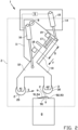
- Figures 1-6 show a splicer 1 according to a first exemplary embodiment of the invention.
- the splicer 1 is used for joining, stitching or splicing a leading end LE and a trailing end TE of a tire component 9.
- the tire component 9 is an apex 9.
- the apex 9 is spliced at the leading end LE and the trailing end TE into an annular or ring shape. In the spliced condition, the apex 9 extends in a circumferential direction C.
- the apex 9 is typically splice on a bead-apex drum.
- the a part of the bead-apex drum is schematically represented by a splice support 8.
- the splice support 8 may be formed by a segment of the aforementioned bead-apex drum, or it may be a dedicated splice table.
- the apex 9 may be spliced in an orientation in which the apex 9 is laying on the bead-apex drum. The apex 9 is subsequently be turned-up in a manner known per se.
- the first splice member 2 is arranged for splicing the leading end LE and the trailing end TE together along a splice path P extending across the tire component 9 from the first side 91 towards the second side 92, i.e. from the tip 94 towards the base 93.
- the splice path P extends transverse or perpendicular to the circumferential direction C.
- the first splice member 2 is moved or driven in a splice direction S in a splice plane Z, parallel to the splice path P, from the first side 91 towards the second side 92, i.e. from the tip 94 towards the base 93, during the splicing of the leading end LE and the trailing end TE together along the splice path P.
- the first splice roller 20 may for example have a smaller diameter than the second splice roller 30 to locally increase the pressing force and/or splicing force at the respective splice roller 20, 30 and/or to enable a more accurate following of the contour of the tire component 9.
- the holder 10 is arranged for holding both the first splice member 2 and the second splice member 3.
- the first splice member 2 and the second splice member 3 are both mounted to the holder 10.
- the first splice member 2 and the second splice member 3 move together with the holder 10 and remain in the same relative position with respect to each other.
- the first splice member 2 is trailing the second splice member 3 in the splice direction S.
- the splicer 1 further comprises a frame or a base 14 that is part of the 'fixed world'.
- the base or frame may be placed directly or indirectly on the factory floor.
- the holder 10 is mounted to and rotatable relative to said base 14 in a swivel motion or a rocking motion M about a swivel axis or a rocking axis B.
- the rocking axis B extends perpendicular to the splice plane Z.
- the rocking axis B is parallel or substantially parallel to the first roller axis A1.
- the first roller axis A1 may be slightly offset with respect to the rocking axis B.
- the first splice roller 20 may be at a slightly different toe with respect to the splice path P and/or the splice direction S, to further promote the closing of the splice between the leading end and the trailing end during the splicing.
- the splicer 1 comprises a rocking drive 15 for driving the rotation of the holder 10 about the rocking axis B.
- the rocking drive 15 is a linear drive, such as a pneumatic cylinder, that is arranged between the holder 10 and the base 14 at a position spaced apart from the rocking axis B.
- the rocking drive 15 may be a suitable rotation drive engaging onto the holder 10 directly at or concentrically to the rocking axis B.
- the rocking drive 15 may be provide with a regulator (not shown), for example a throttle valve, in particular an adjustable throttle valve, for controlling the speed of the rotation about the rocking axis B.
- a regulator for example a throttle valve, in particular an adjustable throttle valve, for controlling the speed of the rotation about the rocking axis B.
- the first splice member 2 and the second splice member 3 are located at a radius from the rocking axis B that is sufficiently large so that the circular trajectory followed by said first splice member 2 and the second splice member 3, together with the holder 10, about the rocking axis B, within the range of the splice path P, extends over only a few degrees about said rocking axis B.
- the circular trajectory can approximate a linear trajectory.
- the splicer 1 further comprises a pressing drive 16 for biasing the first splice member 2 and the second splice member 3 in a pressing direction F transverse or perpendicular to the splice direction S towards the tire component 9.
- the pressing direction F extends in a plane radial to the rocking axis B and/or the splice roller axes A1, A2, i.e. the plane of the drawing in figure 2 .
- the pressing drive 16 can introduce a component radial or substantially radial to the rocking axis B to the otherwise circular trajectory of the first splice member 2 and the second splice member 3, together with the holder 10, about the rocking axis B.
- the first splice member 2 and the second splice member 3 can be pressed tightly against tire component 9 along the splice path P, despite said holder 10 moving along a circular trajectory about the rocking axis B.
- the pressing force exerted by the first splice member 2 and the second splice member 3 onto the tire component 9 will act on said tire component 9 in a direction normal to the surface of the tire component 9 being pressed.
- first splice member 2 and the second splice member 3 may be moved in a pressing direction in or parallel to a direction normal to the surface of the tire component 9 that is being pressed.
- the holder 10 comprises a first holder member 11 that is connected to the base 14 at the rocking axis B and a second holder member 12 that is movable relative to said first holder member 11 in the pressing direction F.
- the second holder member 12 is movable relative to the first holder member 11 over a pair of guide rails 17.
- the pressing drive 16 is a linear drive, i.e. a pneumatic cylinder, that is arranged between the first holder member 11 and the second holder member 12 for biasing the second holder member 12 in the pressing direction F towards the tire component 9 relative to the first holder member 11.
- first splice member 2 and/or the second splice member 3 may be individually biased, i.e. by a biasing member located between the holder 10 and the respective splice member 2, 3.
- the second holder member 12 is movable relative to the first holder member 11 along a stroke distance D that is limited by a lower stroke limiter 18 and an upper stroke limiter 19.
- the stroke limiters 18, 19 may be provided with an elastic buffer material to absorb impacts.
- the movement of the second holder member 12 relative to the first holder member 11 can be faster without damaging the splicer 1 and/or the tire component 9.
- the stroke distance D is larger than the stroke distance required to have the second splice member 3 contact the tire component 9, with the remaining stroke being used to exert the pressing force in the pressing direction F.
- the splicer 1 further comprises a control unit 5 that is operationally and/or electronically connected to the rocking drive 15 and the pressing drive 16 for controlling the said drives 15, 16.
- the control unit 5 may be arranged at the splicer 1 or remotely.
- the control unit 5 is arranged for performing the steps of a method for splicing the leading end LE and the trailing end TE of the tire component 9 together using the first splice member 2 and the second splice member 3.
- the control unit 5 is loaded with instructions or software, or is arranged, adapted or configured for performing the steps of the method.
- the control unit 5 may be connected to or comprise a user interface for controlling the steps semi-automatically, or the control unit 5 may be arranged for fully automatically controlling the splicer 1.
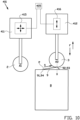
- Figure 1 shows the situation in which the tire component 9 is arranged with the leading end LE and the trailing end TE thereof at the splice support 8.
- the tire component 9 is held in an annular or ring shape.
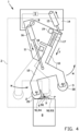
- Figure 2 shows the situation in which the holder 10 is rotated into a position about the rocking axis B in which the second splice member 3, at least in the pressing direction F, is aligned with or at least partially above second side 92 of the tire component 9, in particular near the preparatory splice position X along the splice path P.
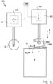
- Figure 3 shows the situation in which the pressing drive 16 is actuated or controlled to drive, bias or move the second holder member 12 towards the tire component 9 in the pressing direction F, thereby causing the second splice member 3 to contact and/or press onto the tire component 9 at the preparatory splice position X along the splice path P. More in particular, as shown in figure 1 , the second splice member 3 is pressed onto the leading end LE and the trailing end TE.
- the pressing can form a local, preliminary joint between the leading end LE and the trailing end TE at the preparatory splice position X to prevent that the leading end LE and the trailing end TE split towards the second side 92 of the tire component 9 as a result of any waving or bulging during the subsequent splicing, as described hereafter.
- step of figure 3 is referred to in the claims as 'step b)'.
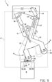
- Figure 4 shows the situation in which the rocking drive 15 has been actuated or controlled to drive or rotate the holder 10 as a whole relative to the base 14 in the rocking motion M about the rocking axis B in a direction such that the second splice roller 30 is rolled along the splice path P in the splice direction S away from the preparatory splice position X.
- the first splice member 2 is brought into a position at the first side 91 of the tire component 9 to initiate splicing of the tire component 9 along the splice path P.
- the first splice roller 30 is located on the splice support 8 at or directly upstream of the first side 91 or the tip 94 of the tire component 9, considered in the splice direction S.
- Figure 5 shows the situation in which the rocking drive 15 has been actuated or controlled to move or rotate the holder 10 further in the rocking motion M about the rocking axis B to roll the first splice roller 30 over the tire component 9 along the splice path P, at least up to preparatory splice position X and optionally up to or beyond the second side 92, i.e. the base 93, of the tire component 9.
- the range of the first splice roller 30 along the splice path P is sufficient to splice the entire width of the tire component 9 in the splice direction S.
- the pressing drive 16 is continuously biasing the second holder member 12 to move in the pressing direction F towards the tire component 9 relative to the first holder member 11. Consequently, the first splice roller 20 can be kept in continuous pressing contact with the tire component 9.
- the pressing force exerted by the pressing drive 16 onto the second holder member 12 is variable.
- the pressure can be set prior to the pressing in step b).
- the pressure may alternatively be varied when carrying out step a) and/or step b). Consequently, also the splice force or pressing force exerted onto the tire component during the splicing in step a) can be varied during the splicing.
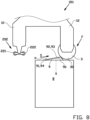
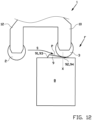
- FIG. 6 shows in more detail the moment that the second splice roller 30 is moved out of the preparatory splice position X in the splice direction S up and over the highest point 95 of the base 93 at the second side 92 of the tire component 9. Note that in the position of the second splice roller 30 that is shown in solid lines, the second splice roller 30 has already moved past the highest point 95 of the base 93 and has started to move down along the opposite slope at the second side 92 of the tire component 9 towards the splice support 8 as a result of the biasing on the second holder member 12 in the pressing direction F.
- the splice support 8 extends at a support height H0.
- the highest point 95 of the base 93 may be deformed excessively when the second splice roller 30 is allowed to move down along the second side 92 of the tire component 9 all the way up to the support height H0 of the splice support 8. To prevent such excessive deformation, the movement of the second splice member 3 is limited in the pressing direction F up to a floating height H1 short of or at a distance spaced apart from said support height H0.
- the floating height H1 may be adjustable, for example by mechanically changing the position of the lower stroke limiter 18 in figure 3 or by adjusting the relative position or the stroke of the pressing drive 16, in particular relative to the splice support 8.
- the floating height H1 can be set prior to the pressing of step b).
- the floating height H1 may be set by allowing the pressing drive 16 to be moved freely and subsequently moving the splice support 8 relative to the splicer 1.
- the pressing drive 16 may for example be released, disconnected or decoupled from its initial position on the first holder member 11, for example by releasing a brake, after which the pressing drive 16 can be moved freely relative to said first holder member 11, for example along a guide rail.
- the splice support 8 may be adapted for such movement in a manner known per se as part of a plurality of radially movable segments of a bead-apex drum.
- the splice support 8 may actively lift the second splice member 3 up to the desired floating height H1, at which point the pressing drive 16 is activated, fixed, connected or coupled again, for example by engaging the brake again, and its stroke distance D is effectively adjusted.
- step b) By performing step b) prior to step a), as shown in figure 1 , the leading end LE and the trailing end TE are pressed first and/or only in the preparatory splice position X. Hence, the leading end LE and the trailing end TE have not yet been exposed to the waving or bulging that occurs during step a). Hence, a preliminary joint can be still be formed reliably prior to the splicing in step a).
- Figure 7 shows an alternative splicer 101 according to a second exemplary embodiment of the invention that differs from the previously discussed splicer 1 in that the second splice member 103 comprises a set of two second splice rollers 131, 132.
- the second splice rollers 131, 132 are rotatable about mutually parallel and spaced apart second roller axes.
- the set of second splice rollers 131, 132 is mounted on a common carriage 130 that is pivotable about a pivot axis G relative to the holder 10, to allow the set of second splice rollers 131, 132 to assume an optimal orientation for pressing and/or forming the preliminary joint in step b).
- the second splice rollers 131, 132 can have a relative small diameter compared to the diameter of the first splice roller 20 to allow a more local and/or higher pressing force in the preparatory splice position X.
- the second splice member 103 may optionally have more than two second splice rollers.
- the second splice roller 131 that is the furthest upstream considered in the splice direction S defines the preparatory splice position X.
- Figure 8 shows a further alternative splicer 201 according to a third exemplary embodiment of the invention that differs from the previously discussed splicers 1, 101 in that the first splice member 202 comprises a set of two first splice rollers 221, 222, mounted to the holder 10 in a similar way as the set of second splice rollers 131, 132 in the previous embodiment.
- the first splice rollers 221, 222 can have a relative small diameter compared to the diameter of the second splice roller 30 to allow a more local and/or higher splicing force along the splice path P.
- Figure 9 shows a further alternative splicer 301 according to a fourth exemplary embodiment of the invention that differs from the previously discussed splicers 1, 101, 201 in that the first splice member 302 comprises a circular segment 320.
- the circular segment 320 can have a relatively large radius to more evenly distribute the splicing force along the splice path P.
- the circular segment 320 can be rocked, rolled and/or swiveled back-and-forth along the splice path P about a swivel axis A301.
- Figure 10 shows a further alternative splicer 301 according to a fifth exemplary embodiment of the invention that differs from the previously discussed splicers 1, 101, 201, 301 in that the first splice member 2 and the second splice member 3 are independently movable relative to each other.
- the further alternative splicer 301 comprises a first holder 411 and a second holder 412 for independently holding the first splice member 2 and the second splice member 3, respectively.
- the first splice member 2 and the second splice member 3 remain rotatable relative to their respective holders 411, 412 about their respective roller axes A1, A2.
- the further alternative splicer 401 is further provided with a first drive 415 for moving the first holder 411 and/or the first splice member 2, a second drive 416 for moving the second holder 412 and/or the second splice member 3 and a control unit 305 that is electronically and/or operationally connected to the first drive 415 and the second drive 416 for independently controlling said drives 415, 416.
- Each drive 415, 416 may comprise a multi-axis manipulator, such as a robotic arm, or an XY-drive system.
- the independent drives 415, 416 may provide greater flexibility when positioning the first splice member 2 and the second splice member 3.
- the movements of may comprise linear trajectories, circular trajectories, non-circular trajectories, or a combination thereof.
- the first splice member 2 may for example accurately follow and/or move along the splice path P.
- the second splice member 3 may be pressed onto the tire component 9 in a pressing direction F perpendicular or normal to the splice support S, or alternatively perpendicular or normal to the orientation of the upper surface of the tire component 9, and return in an opposite direction.
- Figure 11 shows a further alternative splice 501 according to a sixth exemplary embodiment of the invention that differs from the splicer 401 according to the third embodiment of the invention in that its second splice member 503 is or comprises a non-circular pressing member 530, i.e. with a shape that is adapted to optimally match the shape and/or orientation of the tire component 9 in the preparatory splice position X.
- the non-circular pressing member 530 has the shape of a block with a flat pressing surface.
- the non-circular pressing member 530 may have the form of a finger.
- the second splice member 503 is still rotatable relative to the second holder 412 about the second roller axis A2 to allow the non-circular pressing member 530 to assume an optimal orientation for pressing onto the tire component 9.
- the second pressing member 503 may be fixed or an integral part of the second holder 412.
- the pressing in step b) is achieved by pressing the non-circular pressing member 530 onto the leading end LE and the trailing end TE at the preparatory splice position X.
- the non-circular pressing member 530 is not rolled away from said preparatory splice position X. Instead, it is lifted from the tire component 9 after the pressing in step b) in a direction opposite to the pressing direction F.
- Figure 12 shows a variation of the method as shown in figures 1-5 which differs from said method in that the orientation of the tire component 9 relative to the splicer 1 and/or the splice support 8 is reversed.
- the triangular cross section of the tire component 9 now has its base 93 at the first side 91 and its tip 94 at the second side 92. Consequently, the preparatory splice position X is located at or near the tip 94, instead of at or near the base 93.
- Step b) is performed at or near said tip 94 and step a) involves splicing the tire component 9 in the splice direction S from the base 93 at the first side 91 towards the tip 94 at the second side 92.
- FIG. 13 shows a further variation of the method as shown in figures 1-5 which differs from said method in that an alternative tire component 109 is used, having a different cross sectional shape.
- the alternative tire component 109 has a strip body 190 with a rectangular or substantially rectangular cross section. Nonetheless, the alternative tire component 109 still has a first side 191 and a second side 192 which can be pressed in step b) and splice in step a) in substantially the same way.
- the tire component may have a non-rectangular, non-triangular cross section, for example a crowned or trapezoidal cross section.
- the method according to the present invention can alternatively be carried out by a single splice member, for example the first splice member 2 of figure 10 .
- the control unit 405 is operationally connected to the drive 415 and configured for controlling the drive 415 to first move the single splice member 2 to the preparatory splice position X for the pressing in step b), and subsequently moving the single splice member 2 along the splice path P across the tire component 9 for the splicing in step a).
- the splicers 1, 101, 201, 301, 401, 501 are used to splice the leading end LE and the trailing end TE in an overlapping configuration, such as the one shown schematically in figure 14 .
- the leading end LE and the trailing end TE are cut obliquely.
- the overlapping section of the trailing end TE can be tightly adhered to the underlying section of the leading end LE by pressing onto the tire component 9 in the pressing direction F with one of the aforementioned splicers 1, 101, 201, 301, 401, 501.
- an alternative tire component 209 may be provided having a non-overlapping leading end LE and trailing end TE.
- the leading end LE and the trailing end TE have been cut at a right angle.
- Such leading end LE and trailing end TE are butt-spliced.
- a further alternative splicer 601 may be provided according to a seventh exemplary embodiment of the invention.
- Said further alternative splicer 601 differs from the previously discussed splicers 1, 101, 201, 301, 401, 501 in that it has at least one second splice member 631 and preferably a set of two second splice members 631, 632 which are angled to the splice plane Z so as to exert a pressing force onto at least one of the leading end LE and the trailing end TE in a pressing direction F1, F2 towards the other of the leading end LE and the trailing end TE.
- two second splice members 631, 632 simultaneously exert a pressing force onto the respective ends LE, TE from opposite sides of the splice plane Z.
Landscapes
- Engineering & Computer Science (AREA)
- Mechanical Engineering (AREA)
- Textile Engineering (AREA)
- Physics & Mathematics (AREA)
- Fluid Mechanics (AREA)
- Tyre Moulding (AREA)
Claims (20)
- Verfahren zum Zusammenspleißen eines vorderen Endes und eines hinteren Endes einer Reifenkomponente, wobei das Verfahren die folgenden Schritte umfasst:a) Zusammenspleißen des vorderen Endes (LE) und des hinteren Endes (TE) entlang eines Spleißpfads (P), der sich quer über die Reifenkomponente in einer Spleißrichtung (S) von einer ersten Seite (91) der Reifenkomponente zu einer der ersten Seite gegenüberliegenden zweiten Seite (92) der Reifenkomponente erstreckt; undb) vor dem Spleißen Ausbilden einer vorläufigen Verbindung zwischen dem vorderen Ende und dem hinteren Ende an einer Vorbereitungsspleißposition (X) entlang des Spleißpfads;wobei die Vorbereitungsspleißposition (X) von der ersten Seite (91) beabstandet ist.
- Verfahren nach Anspruch 1, wobei die Vorbereitungsspleißposition näher an der zweiten Seite als an der ersten Seite liegt.
- Verfahren nach Anspruch 1 oder 2, wobei das vordere Ende und das hintere Ende nur durch das Spleißen von Schritt a) zwischen der ersten Seite und der Vorbereitungsspleißposition gespleißt werden.
- Verfahren nach einem der vorhergehenden Ansprüche, wobei das Spleißen von Schritt a) kontinuierlich von der ersten Seite bis zur zweiten Seite ausgeführt wird.
- Verfahren nach einem der vorhergehenden Ansprüche, wobei das vordere Ende und das hintere Ende in Schritt b) in einer zur Spleißrichtung quer verlaufenden oder senkrechten Pressrichtung gepresst werden.
- Verfahren nach einem der vorhergehenden Ansprüche, wobei die Reifenkomponente ein Kernreiter ist,
vorzugsweise wobei der Kernreiter einen dreieckigen Querschnitt mit einer Basis und einer Spitze aufweist, wobei die erste Seite die Spitze ist und die zweite Seite die Basis ist, oder wobei die erste Seite die Basis ist und die zweite Seite die Spitze ist. - Verfahren nach einem der vorhergehenden Ansprüche, wobei ein erstes Spleißelement für das Spleißen in Schritt a) verwendet wird und ein zweites Spleißelement für das Ausbilden der vorläufigen Verbindung in Schritt b) verwendet wird.
- Verfahren nach Anspruch 7, wobei das erste Spleißelement das zweite Spleißelement in der Spleißrichtung nachzieht, vorzugsweise wobei das erste Spleißelement und das zweite Spleißelement unabhängig relativ zueinander bewegbar sind.
- Verfahren nach Anspruch 7 oder 8, wobei das erste Spleißelement eine erste Spleißwalze ist, die um eine erste Walzenachse drehbar ist, wobei das Spleißen in Schritt a) durch Rollen der ersten Spleißwalze entlang des Spleißpfads in der Spleißrichtung bewerkstelligt wird,vorzugsweise wobei das erste Spleißelement entlang des Spleißpfads als Teil einer Wippbewegung um eine Wippachse bewegt wird, die parallel zur ersten Walzenachse und von ihr beabstandet ist,noch bevorzugter wobei das erste Spleißelement und das zweite Spleißelement bei der Wippbewegung um die Wippachse zusammen bewegt werden.
- Verfahren nach Anspruch 8 oder 9, wobei das zweite Spleißelement mindestens ein zweite Spleißwalze umfasst, wobei das Verfahren ferner den Schritt des Rollens der mindestens einen zweiten Spleißwalze entlang des Spleißpfads in der Spleißrichtung weg von der Vorbereitungsspleißposition nach dem Ausbilden der vorläufigen Verbindung in Schritt b) umfasst; und/oder
wobei das zweite Spleißelement ein nicht kreisförmiges Presselement umfasst, wobei das Pressen in Schritt b) durch Pressen des nicht kreisförmigen Presselements auf das vordere Ende und das hintere Ende an der Vorbereitungsspleißposition bewerkstelligt wird. - Verfahren nach einem der Ansprüche 8 bis 10, wobei das vordere Ende und das hintere Ende auf einer Spleißstütze abgestützt werden, die sich in einer Stützhöhe erstreckt, wobei das zweite Spleißelement in einer zur Spleißrichtung quer verlaufenden oder senkrechten Pressrichtung in Richtung der Spleißstütze bis zu einer Schwebehöhe nahe der Stützhöhe bewegbar ist,
vorzugsweise wobei die Schwebehöhe justierbar ist, wobei die Schwebehöhe vor dem Ausbilden der vorläufigen Verbindung von Schritt b) eingestellt wird. - Verfahren nach einem der vorhergehenden Ansprüche, wobei das vordere Ende und das hintere Ende in Schritt b) mit einer Presskraft gepresst werden, die variabel ist, wobei die Presskraft während des Pressens von Schritt b) oder davor eingestellt wird; und/oder
wobei das vordere Ende und das hintere Ende in Schritt a) mit einer Spleißkraft gespleißt werden, die variabel ist, wobei die Spleißkraft während des Spleißens von Schritt a) oder davor eingestellt wird. - Spleißvorrichtung zum Zusammenspleißen eines vorderen Endes und eines hinteren Endes einer Reifenkomponente, insbesondere eines Kernreiters, wobei die Spleißvorrichtung ein erstes Spleißelement (2) zum Zusammenspleißen des vorderen Endes (LE) und des hinteren Endes (TE) entlang eines Spleißpfads (P) umfasst, der sich quer über die Reifenkomponente in einer Spleißrichtung von einer ersten Seite (91) der Reifenkomponente zu einer der ersten Seite gegenüberliegenden zweiten Seite (92) der Reifenkomponente erstreckt,
dadurch gekennzeichnet, dass die Spleißvorrichtung ferner ein zweites Spleißelement (3) zum Ausbilden einer vorläufigen Verbindung zwischen dem vorderen Ende und dem hinteren Ende an einer Vorbereitungsspleißposition (X) entlang des Spleißpfads umfasst, wobei die Vorbereitungsspleißposition (X) von der ersten Seite (91) beabstandet ist. - Spleißvorrichtung nach Anspruch 13, wobei die Vorbereitungsspleißposition näher an der zweiten Seite als an der ersten Seite liegt.
- Spleißvorrichtung nach Anspruch 13 oder 14, wobei das erste Spleißelement das zweite Spleißelement in der Spleißrichtung nachzieht.
- Spleißvorrichtung nach einem der Ansprüche 13 bis 15, wobei das erste Spleißelement eine erste Spleißwalze ist, die um eine erste Walzenachse drehbar ist; oder
wobei das erste Spleißelement ein kreisförmiges Segment umfasst, das um eine Schwenkachse drehbar ist. - Spleißvorrichtung nach einem der Ansprüche 13 bis 16, wobei die Spleißvorrichtung eine Basis und einen Halter umfasst, der relativ zur Basis in einer Wippbewegung um eine Wippachse drehbar ist, wobei das erste Spleißelement an den Halter montiert und zusammen mit dem Halter bei der Wippbewegung um die Wippachse bewegbar ist,vorzugsweise wobei das zweite Spleißelement an den Halter montiert und zusammen mit dem ersten Spleißelement bei der Wippbewegung um die Wippachse bewegbar ist; und/oderwobei die Spleißvorrichtung einen Wippantrieb zum Antreiben der Drehung des Halters um die Wippachse umfasst.
- Spleißvorrichtung nach einem der Ansprüche 13 bis 17, wobei das zweite Spleißelement eine zweite Spleißwalze umfasst, die um eine zweite Walzenachse drehbar ist; oder
wobei das zweite Spleißelement ein nicht kreisförmiges Presselement umfasst. - Spleißvorrichtung nach einem der Ansprüche 13 bis 18, wobei die Spleißvorrichtung einen oder mehrere Antriebe zum Antreiben des ersten Spleißelements und des zweiten Spleißelements und eine Steuereinheit umfasst, die betriebsfähig mit dem einen oder den mehreren Antrieben verbunden ist, wobei die Steuereinheit dazu eingerichtet ist, den einen oder die mehreren Antriebe zu steuern, um die folgenden Schritte auszuführen:a) Bewegen des ersten Spleißelements entlang des Spleißpfads in der Spleißrichtung zum Zusammenspleißen des vorderen Endes und des hinteren Endes entlang des Spleißpfads; undb) vor der Bewegung in Schritt a) Bewegen des zweiten Spleißelements zur Vorbereitungsspleißposition zum Ausbilden einer vorläufigen Verbindung zwischen dem vorderen Ende und dem hinteren Ende an der Vorbereitungsspleißposition.
- Spleißvorrichtung zum Zusammenspleißen eines vorderen Endes (LE) und eines hinteren Endes (TE) einer Reifenkomponente, insbesondere eines Kernreiters, wobei die Spleißvorrichtung ein Spleißelement (2), einen Antrieb (415) zum Bewegen des Spleißelements und eine Steuereinheit (405), die betriebsfähig mit dem Antrieb (415) verbunden ist, umfasst, wobei die Steuereinheit dazu eingerichtet ist, den Antrieb zu steuern, um die folgenden Schritte auszuführen:a) Bewegen des Spleißelements (2) entlang eines Spleißpfads (P), der sich quer über die Reifenkomponente in einer Spleißrichtung von einer ersten Seite (91) der Reifenkomponente zu einer der ersten Seite gegenüberliegenden zweiten Seite (92) der Reifenkomponente erstreckt, um das vordere Ende (LE) und das hintere Ende (TE) entlang des Spleißpfads zusammenzuspleißen; undb) vor der Bewegung in Schritt a) Bewegen des Spleißelements (2) zu einer Vorbereitungsspleißposition (X) entlang des Spleißpfads zum Ausbilden einer vorläufigen Verbindung zwischen dem vorderen Ende und dem hinteren Ende an der Vorbereitungsspleißposition (X) entlang des Spleißpfads,wobei die Vorbereitungsspleißposition (X) von der ersten Seite (91) beabstandet ist.
Priority Applications (1)
| Application Number | Priority Date | Filing Date | Title |
|---|---|---|---|
| RS20250522A RS66844B1 (sr) | 2021-03-01 | 2022-02-16 | Postupak i uređaj za spajanje za spajanje vodećeg kraja i pratećeg kraja komponente pneumatika |
Applications Claiming Priority (2)
| Application Number | Priority Date | Filing Date | Title |
|---|---|---|---|
| NL2027675A NL2027675B1 (en) | 2021-03-01 | 2021-03-01 | Method and splicer for splicing a leading end and a trailing end of a tire component |
| PCT/NL2022/050079 WO2022186688A1 (en) | 2021-03-01 | 2022-02-16 | Method and splicer for splicing a leading end and a trailing end of a tire component |
Publications (3)
| Publication Number | Publication Date |
|---|---|
| EP4301583A1 EP4301583A1 (de) | 2024-01-10 |
| EP4301583C0 EP4301583C0 (de) | 2025-03-19 |
| EP4301583B1 true EP4301583B1 (de) | 2025-03-19 |
Family
ID=76159904
Family Applications (1)
| Application Number | Title | Priority Date | Filing Date |
|---|---|---|---|
| EP22705178.6A Active EP4301583B1 (de) | 2021-03-01 | 2022-02-16 | Verfahren und spleisser zum spleissen eines vorderen endes und eines hinteren endes einer reifenkomponente |
Country Status (15)
| Country | Link |
|---|---|
| US (1) | US20240140046A1 (de) |
| EP (1) | EP4301583B1 (de) |
| JP (2) | JP2023519060A (de) |
| KR (1) | KR20230152729A (de) |
| CN (2) | CN114986959A (de) |
| BR (1) | BR112023017037A2 (de) |
| CA (1) | CA3207342A1 (de) |
| ES (1) | ES3015757T3 (de) |
| HU (1) | HUE071259T2 (de) |
| MX (1) | MX2023009395A (de) |
| NL (1) | NL2027675B1 (de) |
| PL (1) | PL4301583T3 (de) |
| RS (1) | RS66844B1 (de) |
| TW (1) | TW202247995A (de) |
| WO (1) | WO2022186688A1 (de) |
Families Citing this family (3)
| Publication number | Priority date | Publication date | Assignee | Title |
|---|---|---|---|---|
| JP7434904B2 (ja) * | 2020-01-08 | 2024-02-21 | 住友ゴム工業株式会社 | 生タイヤの製造方法 |
| NL2027675B1 (en) * | 2021-03-01 | 2022-09-20 | Vmi Holland Bv | Method and splicer for splicing a leading end and a trailing end of a tire component |
| NL2038263B1 (en) * | 2024-07-18 | 2026-02-05 | Vmi Holland Bv | Method, applicator, use of an applicator and computer-readable medium for applying an elastomeric strip around a receiving device |
Family Cites Families (16)
| Publication number | Priority date | Publication date | Assignee | Title |
|---|---|---|---|---|
| IT1218972B (it) * | 1988-01-22 | 1990-04-24 | Firestone Int Dev Spa | Dispositivo automatico per la giunzione trasversale di materiale elastomerico verde in foglio |
| DE102004024715B4 (de) * | 2004-05-19 | 2017-06-01 | Continental Reifen Deutschland Gmbh | Spleißvorrichtung |
| JP4751243B2 (ja) * | 2006-06-01 | 2011-08-17 | 住友ゴム工業株式会社 | コードプライの側縁部接合装置 |
| CN102497973B (zh) * | 2009-07-15 | 2014-11-12 | 株式会社普利司通 | 轮胎构成构件的制造装置及制造方法 |
| WO2011125405A1 (ja) * | 2010-04-09 | 2011-10-13 | 株式会社ブリヂストン | タイヤ構成部材の接合装置及び製造方法 |
| JP5495267B2 (ja) * | 2010-04-14 | 2014-05-21 | 株式会社ブリヂストン | タイヤ構成部材の製造装置及び製造方法 |
| NL2005819C2 (nl) * | 2010-12-06 | 2012-06-07 | Vmi Holland Bv | Lasinrichting en werkwijze voor het aan elkaar lassen van stroken van rubbermateriaal. |
| JP5844591B2 (ja) * | 2011-09-27 | 2016-01-20 | 株式会社ブリヂストン | タイヤ構成部材の接合装置及び製造方法 |
| JP5859281B2 (ja) * | 2011-11-15 | 2016-02-10 | 株式会社ブリヂストン | ゴム部材の接合装置及び接合方法 |
| JP6297394B2 (ja) * | 2014-04-15 | 2018-03-20 | 東洋ゴム工業株式会社 | ビード部材の製造方法及び製造装置 |
| JP2018012306A (ja) * | 2016-07-22 | 2018-01-25 | 株式会社ブリヂストン | 空気入りタイヤの製造方法、および空気入りタイヤ |
| JP7017884B2 (ja) * | 2017-09-04 | 2022-02-09 | Toyo Tire株式会社 | タイヤ部材の製造装置 |
| NL2019785B1 (en) * | 2017-10-23 | 2019-04-29 | Vmi Holland Bv | Tire building apparatus and method for joining or cutting tire components |
| JP7225806B2 (ja) * | 2019-01-08 | 2023-02-21 | 住友ゴム工業株式会社 | ゴム部材成形方法及びこれに用いられる押圧ローラ |
| EP4017717B1 (de) * | 2019-08-21 | 2024-09-11 | Bridgestone Americas Tire Operations, LLC | Vorrichtung und verfahren zum automatischen nähen von reifenlagen |
| NL2027675B1 (en) * | 2021-03-01 | 2022-09-20 | Vmi Holland Bv | Method and splicer for splicing a leading end and a trailing end of a tire component |
-
2021
- 2021-03-01 NL NL2027675A patent/NL2027675B1/en active
-
2022
- 2022-02-16 US US18/278,612 patent/US20240140046A1/en active Pending
- 2022-02-16 BR BR112023017037A patent/BR112023017037A2/pt unknown
- 2022-02-16 RS RS20250522A patent/RS66844B1/sr unknown
- 2022-02-16 PL PL22705178.6T patent/PL4301583T3/pl unknown
- 2022-02-16 CA CA3207342A patent/CA3207342A1/en active Pending
- 2022-02-16 EP EP22705178.6A patent/EP4301583B1/de active Active
- 2022-02-16 ES ES22705178T patent/ES3015757T3/es active Active
- 2022-02-16 MX MX2023009395A patent/MX2023009395A/es unknown
- 2022-02-16 JP JP2022535574A patent/JP2023519060A/ja active Pending
- 2022-02-16 HU HUE22705178A patent/HUE071259T2/hu unknown
- 2022-02-16 WO PCT/NL2022/050079 patent/WO2022186688A1/en not_active Ceased
- 2022-02-16 KR KR1020237033379A patent/KR20230152729A/ko active Pending
- 2022-03-01 TW TW111107211A patent/TW202247995A/zh unknown
- 2022-03-01 CN CN202210199064.3A patent/CN114986959A/zh active Pending
- 2022-03-01 CN CN202220441316.4U patent/CN217373570U/zh active Active
-
2024
- 2024-07-29 JP JP2024122908A patent/JP7704941B2/ja active Active
Also Published As
| Publication number | Publication date |
|---|---|
| CN217373570U (zh) | 2022-09-06 |
| RS66844B1 (sr) | 2025-06-30 |
| NL2027675B1 (en) | 2022-09-20 |
| WO2022186688A1 (en) | 2022-09-09 |
| CA3207342A1 (en) | 2022-09-09 |
| EP4301583A1 (de) | 2024-01-10 |
| JP2023519060A (ja) | 2023-05-10 |
| MX2023009395A (es) | 2023-08-23 |
| EP4301583C0 (de) | 2025-03-19 |
| TW202247995A (zh) | 2022-12-16 |
| NL2027675A (en) | 2022-09-20 |
| BR112023017037A2 (pt) | 2023-09-26 |
| KR20230152729A (ko) | 2023-11-03 |
| PL4301583T3 (pl) | 2025-07-28 |
| HUE071259T2 (hu) | 2025-08-28 |
| JP2024156776A (ja) | 2024-11-06 |
| CN114986959A (zh) | 2022-09-02 |
| ES3015757T3 (en) | 2025-05-07 |
| US20240140046A1 (en) | 2024-05-02 |
| JP7704941B2 (ja) | 2025-07-08 |
Similar Documents
| Publication | Publication Date | Title |
|---|---|---|
| EP4301583B1 (de) | Verfahren und spleisser zum spleissen eines vorderen endes und eines hinteren endes einer reifenkomponente | |
| US20220212429A1 (en) | Device and method for producing unvulcanized band-shaped rubber member | |
| US20190358841A1 (en) | Cutting device and method for cutting-off a length of a continuous strip to form a tire component | |
| JP7087090B2 (ja) | タイヤを成型するための装置およびタイヤ部品を接合又は切断するための方法 | |
| EP1535727B1 (de) | Vorrichtung und verfahren zum kleben eines reifenkomponentenglieds | |
| NL8900031A (nl) | Verbindingsinrichting voor met koord versterkte bandvormige materialen. | |
| EP4294608B1 (de) | Aufbringvorrichtung, reifenaufbauvorrichtung und verfarhen zum auftragen von streifen auf eine trommel | |
| US6761329B2 (en) | Apparatus and method of producing rolls of bags | |
| KR101739891B1 (ko) | 타이어 비드를 위한 환형 에이펙스 필러를 형성하기 위한 장치 및 방법 | |
| EP4373659B1 (de) | Versorgungsvorrichtung für zwei reifenkomponenten und verfahren zur versorgung einer reifenaufbautrommel mit zwei reifenkomponenten | |
| NL2029796B1 (en) | Cutting device and method for cutting a strip and production line for applying an apex to a bead. | |
| CN115195175B (zh) | 将三角胶条缝合到胎圈的胎圈-三角胶条缝合装置、胎圈-三角胶条工位以及方法 | |
| CN224183824U (zh) | 用于将轮胎部件施加到轮胎成型鼓的施加器 | |
| NL2015978B1 (en) | Joining apparatus for joining tire components. | |
| NL2037008B1 (en) | Applicator, tire building machine and method for applying a tire component to a tire building drum | |
| NL2027901B1 (en) | Method for positioning a strip for splicing, gripper for supplying said strip for splicing and tire building machine comprising said gripper | |
| JP7679723B2 (ja) | コード材料の貼付装置 | |
| NL2037019B1 (en) | Conveying apparatus and method for conveying a tire component | |
| JP2024512883A (ja) | タイヤ構成要素を切断するための切断デバイスおよび方法 | |
| KR200327944Y1 (ko) | 목재패널 에지밴딩기 | |
| JPH02145328A (ja) | ビードエイペックスの貼付方法及び装置 | |
| JP2725056B2 (ja) | シート分割巻取装置の巻取準備装置 | |
| EP1281649A1 (de) | Vorrichtung und Verfahren zur Produktion von Rollen von Beuteln |
Legal Events
| Date | Code | Title | Description |
|---|---|---|---|
| STAA | Information on the status of an ep patent application or granted ep patent |
Free format text: STATUS: UNKNOWN |
|
| STAA | Information on the status of an ep patent application or granted ep patent |
Free format text: STATUS: THE INTERNATIONAL PUBLICATION HAS BEEN MADE |
|
| PUAI | Public reference made under article 153(3) epc to a published international application that has entered the european phase |
Free format text: ORIGINAL CODE: 0009012 |
|
| STAA | Information on the status of an ep patent application or granted ep patent |
Free format text: STATUS: REQUEST FOR EXAMINATION WAS MADE |
|
| 17P | Request for examination filed |
Effective date: 20230713 |
|
| AK | Designated contracting states |
Kind code of ref document: A1 Designated state(s): AL AT BE BG CH CY CZ DE DK EE ES FI FR GB GR HR HU IE IS IT LI LT LU LV MC MK MT NL NO PL PT RO RS SE SI SK SM TR |
|
| DAV | Request for validation of the european patent (deleted) | ||
| DAX | Request for extension of the european patent (deleted) | ||
| GRAP | Despatch of communication of intention to grant a patent |
Free format text: ORIGINAL CODE: EPIDOSNIGR1 |
|
| STAA | Information on the status of an ep patent application or granted ep patent |
Free format text: STATUS: GRANT OF PATENT IS INTENDED |
|
| INTG | Intention to grant announced |
Effective date: 20241010 |
|
| GRAS | Grant fee paid |
Free format text: ORIGINAL CODE: EPIDOSNIGR3 |
|
| GRAA | (expected) grant |
Free format text: ORIGINAL CODE: 0009210 |
|
| STAA | Information on the status of an ep patent application or granted ep patent |
Free format text: STATUS: THE PATENT HAS BEEN GRANTED |
|
| AK | Designated contracting states |
Kind code of ref document: B1 Designated state(s): AL AT BE BG CH CY CZ DE DK EE ES FI FR GB GR HR HU IE IS IT LI LT LU LV MC MK MT NL NO PL PT RO RS SE SI SK SM TR |
|
| REG | Reference to a national code |
Ref country code: GB Ref legal event code: FG4D |
|
| REG | Reference to a national code |
Ref country code: CH Ref legal event code: EP |
|
| REG | Reference to a national code |
Ref country code: IE Ref legal event code: FG4D |
|
| REG | Reference to a national code |
Ref country code: DE Ref legal event code: R096 Ref document number: 602022011973 Country of ref document: DE |
|
| U01 | Request for unitary effect filed |
Effective date: 20250402 |
|
| U07 | Unitary effect registered |
Designated state(s): AT BE BG DE DK EE FI FR IT LT LU LV MT NL PT RO SE SI Effective date: 20250409 |
|
| PG25 | Lapsed in a contracting state [announced via postgrant information from national office to epo] |
Ref country code: NO Free format text: LAPSE BECAUSE OF FAILURE TO SUBMIT A TRANSLATION OF THE DESCRIPTION OR TO PAY THE FEE WITHIN THE PRESCRIBED TIME-LIMIT Effective date: 20250619 |
|
| PG25 | Lapsed in a contracting state [announced via postgrant information from national office to epo] |
Ref country code: HR Free format text: LAPSE BECAUSE OF FAILURE TO SUBMIT A TRANSLATION OF THE DESCRIPTION OR TO PAY THE FEE WITHIN THE PRESCRIBED TIME-LIMIT Effective date: 20250319 |
|
| PG25 | Lapsed in a contracting state [announced via postgrant information from national office to epo] |
Ref country code: GR Free format text: LAPSE BECAUSE OF FAILURE TO SUBMIT A TRANSLATION OF THE DESCRIPTION OR TO PAY THE FEE WITHIN THE PRESCRIBED TIME-LIMIT Effective date: 20250620 |
|
| REG | Reference to a national code |
Ref country code: SK Ref legal event code: T3 Ref document number: E 46547 Country of ref document: SK |
|
| REG | Reference to a national code |
Ref country code: HU Ref legal event code: AG4A Ref document number: E071259 Country of ref document: HU |
|
| PG25 | Lapsed in a contracting state [announced via postgrant information from national office to epo] |
Ref country code: SM Free format text: LAPSE BECAUSE OF FAILURE TO SUBMIT A TRANSLATION OF THE DESCRIPTION OR TO PAY THE FEE WITHIN THE PRESCRIBED TIME-LIMIT Effective date: 20250319 |
|
| PG25 | Lapsed in a contracting state [announced via postgrant information from national office to epo] |
Ref country code: IS Free format text: LAPSE BECAUSE OF FAILURE TO SUBMIT A TRANSLATION OF THE DESCRIPTION OR TO PAY THE FEE WITHIN THE PRESCRIBED TIME-LIMIT Effective date: 20250719 |
|
| PLBE | No opposition filed within time limit |
Free format text: ORIGINAL CODE: 0009261 |
|
| STAA | Information on the status of an ep patent application or granted ep patent |
Free format text: STATUS: NO OPPOSITION FILED WITHIN TIME LIMIT |
|
| REG | Reference to a national code |
Ref country code: CH Ref legal event code: L10 Free format text: ST27 STATUS EVENT CODE: U-0-0-L10-L00 (AS PROVIDED BY THE NATIONAL OFFICE) Effective date: 20260128 |
|
| 26N | No opposition filed |
Effective date: 20251222 |
|
| PGFP | Annual fee paid to national office [announced via postgrant information from national office to epo] |
Ref country code: HU Payment date: 20260220 Year of fee payment: 5 |
|
| U20 | Renewal fee for the european patent with unitary effect paid |
Year of fee payment: 5 Effective date: 20260225 |
|
| PGFP | Annual fee paid to national office [announced via postgrant information from national office to epo] |
Ref country code: RS Payment date: 20260206 Year of fee payment: 5 |
|
| PGFP | Annual fee paid to national office [announced via postgrant information from national office to epo] |
Ref country code: TR Payment date: 20260210 Year of fee payment: 5 |