EP4294608B1 - Aufbringvorrichtung, reifenaufbauvorrichtung und verfarhen zum auftragen von streifen auf eine trommel - Google Patents
Aufbringvorrichtung, reifenaufbauvorrichtung und verfarhen zum auftragen von streifen auf eine trommel Download PDFInfo
- Publication number
- EP4294608B1 EP4294608B1 EP22703728.0A EP22703728A EP4294608B1 EP 4294608 B1 EP4294608 B1 EP 4294608B1 EP 22703728 A EP22703728 A EP 22703728A EP 4294608 B1 EP4294608 B1 EP 4294608B1
- Authority
- EP
- European Patent Office
- Prior art keywords
- roller
- chamber
- applicator
- roller body
- strip
- Prior art date
- Legal status (The legal status is an assumption and is not a legal conclusion. Google has not performed a legal analysis and makes no representation as to the accuracy of the status listed.)
- Active
Links
Images


Classifications
-
- B—PERFORMING OPERATIONS; TRANSPORTING
- B26—HAND CUTTING TOOLS; CUTTING; SEVERING
- B26D—CUTTING; DETAILS COMMON TO MACHINES FOR PERFORATING, PUNCHING, CUTTING-OUT, STAMPING-OUT OR SEVERING
- B26D1/00—Cutting through work characterised by the nature or movement of the cutting member or particular materials not otherwise provided for; Apparatus or machines therefor; Cutting members therefor
- B26D1/01—Cutting through work characterised by the nature or movement of the cutting member or particular materials not otherwise provided for; Apparatus or machines therefor; Cutting members therefor involving a cutting member which does not travel with the work
- B26D1/12—Cutting through work characterised by the nature or movement of the cutting member or particular materials not otherwise provided for; Apparatus or machines therefor; Cutting members therefor involving a cutting member which does not travel with the work having a cutting member moving about an axis
- B26D1/14—Cutting through work characterised by the nature or movement of the cutting member or particular materials not otherwise provided for; Apparatus or machines therefor; Cutting members therefor involving a cutting member which does not travel with the work having a cutting member moving about an axis with a circular cutting member, e.g. disc cutter
- B26D1/157—Cutting through work characterised by the nature or movement of the cutting member or particular materials not otherwise provided for; Apparatus or machines therefor; Cutting members therefor involving a cutting member which does not travel with the work having a cutting member moving about an axis with a circular cutting member, e.g. disc cutter rotating about a movable axis
- B26D1/1575—Cutting through work characterised by the nature or movement of the cutting member or particular materials not otherwise provided for; Apparatus or machines therefor; Cutting members therefor involving a cutting member which does not travel with the work having a cutting member moving about an axis with a circular cutting member, e.g. disc cutter rotating about a movable axis for thin material, e.g. for sheets, strips or the like
-
- B—PERFORMING OPERATIONS; TRANSPORTING
- B26—HAND CUTTING TOOLS; CUTTING; SEVERING
- B26D—CUTTING; DETAILS COMMON TO MACHINES FOR PERFORATING, PUNCHING, CUTTING-OUT, STAMPING-OUT OR SEVERING
- B26D1/00—Cutting through work characterised by the nature or movement of the cutting member or particular materials not otherwise provided for; Apparatus or machines therefor; Cutting members therefor
- B26D1/01—Cutting through work characterised by the nature or movement of the cutting member or particular materials not otherwise provided for; Apparatus or machines therefor; Cutting members therefor involving a cutting member which does not travel with the work
- B26D1/12—Cutting through work characterised by the nature or movement of the cutting member or particular materials not otherwise provided for; Apparatus or machines therefor; Cutting members therefor involving a cutting member which does not travel with the work having a cutting member moving about an axis
- B26D1/14—Cutting through work characterised by the nature or movement of the cutting member or particular materials not otherwise provided for; Apparatus or machines therefor; Cutting members therefor involving a cutting member which does not travel with the work having a cutting member moving about an axis with a circular cutting member, e.g. disc cutter
- B26D1/157—Cutting through work characterised by the nature or movement of the cutting member or particular materials not otherwise provided for; Apparatus or machines therefor; Cutting members therefor involving a cutting member which does not travel with the work having a cutting member moving about an axis with a circular cutting member, e.g. disc cutter rotating about a movable axis
- B26D1/16—Cutting through work characterised by the nature or movement of the cutting member or particular materials not otherwise provided for; Apparatus or machines therefor; Cutting members therefor involving a cutting member which does not travel with the work having a cutting member moving about an axis with a circular cutting member, e.g. disc cutter rotating about a movable axis mounted on a movable arm or the like
- B26D1/165—Cutting through work characterised by the nature or movement of the cutting member or particular materials not otherwise provided for; Apparatus or machines therefor; Cutting members therefor involving a cutting member which does not travel with the work having a cutting member moving about an axis with a circular cutting member, e.g. disc cutter rotating about a movable axis mounted on a movable arm or the like for thin material, e.g. for sheets, strips or the like
-
- B—PERFORMING OPERATIONS; TRANSPORTING
- B26—HAND CUTTING TOOLS; CUTTING; SEVERING
- B26D—CUTTING; DETAILS COMMON TO MACHINES FOR PERFORATING, PUNCHING, CUTTING-OUT, STAMPING-OUT OR SEVERING
- B26D1/00—Cutting through work characterised by the nature or movement of the cutting member or particular materials not otherwise provided for; Apparatus or machines therefor; Cutting members therefor
- B26D1/01—Cutting through work characterised by the nature or movement of the cutting member or particular materials not otherwise provided for; Apparatus or machines therefor; Cutting members therefor involving a cutting member which does not travel with the work
- B26D1/12—Cutting through work characterised by the nature or movement of the cutting member or particular materials not otherwise provided for; Apparatus or machines therefor; Cutting members therefor involving a cutting member which does not travel with the work having a cutting member moving about an axis
- B26D1/14—Cutting through work characterised by the nature or movement of the cutting member or particular materials not otherwise provided for; Apparatus or machines therefor; Cutting members therefor involving a cutting member which does not travel with the work having a cutting member moving about an axis with a circular cutting member, e.g. disc cutter
- B26D1/157—Cutting through work characterised by the nature or movement of the cutting member or particular materials not otherwise provided for; Apparatus or machines therefor; Cutting members therefor involving a cutting member which does not travel with the work having a cutting member moving about an axis with a circular cutting member, e.g. disc cutter rotating about a movable axis
- B26D1/18—Cutting through work characterised by the nature or movement of the cutting member or particular materials not otherwise provided for; Apparatus or machines therefor; Cutting members therefor involving a cutting member which does not travel with the work having a cutting member moving about an axis with a circular cutting member, e.g. disc cutter rotating about a movable axis mounted on a movable carriage
- B26D1/185—Cutting through work characterised by the nature or movement of the cutting member or particular materials not otherwise provided for; Apparatus or machines therefor; Cutting members therefor involving a cutting member which does not travel with the work having a cutting member moving about an axis with a circular cutting member, e.g. disc cutter rotating about a movable axis mounted on a movable carriage for thin material, e.g. for sheets, strips or the like
-
- B—PERFORMING OPERATIONS; TRANSPORTING
- B26—HAND CUTTING TOOLS; CUTTING; SEVERING
- B26D—CUTTING; DETAILS COMMON TO MACHINES FOR PERFORATING, PUNCHING, CUTTING-OUT, STAMPING-OUT OR SEVERING
- B26D3/00—Cutting work characterised by the nature of the cut made; Apparatus therefor
- B26D3/10—Making cuts of other than simple rectilinear form
- B26D3/11—Making cuts of other than simple rectilinear form to obtain pieces of spiral or helical form
-
- B—PERFORMING OPERATIONS; TRANSPORTING
- B26—HAND CUTTING TOOLS; CUTTING; SEVERING
- B26D—CUTTING; DETAILS COMMON TO MACHINES FOR PERFORATING, PUNCHING, CUTTING-OUT, STAMPING-OUT OR SEVERING
- B26D7/00—Details of apparatus for cutting, cutting-out, stamping-out, punching, perforating, or severing by means other than cutting
- B26D7/0006—Means for guiding the cutter
-
- B—PERFORMING OPERATIONS; TRANSPORTING
- B26—HAND CUTTING TOOLS; CUTTING; SEVERING
- B26D—CUTTING; DETAILS COMMON TO MACHINES FOR PERFORATING, PUNCHING, CUTTING-OUT, STAMPING-OUT OR SEVERING
- B26D7/00—Details of apparatus for cutting, cutting-out, stamping-out, punching, perforating, or severing by means other than cutting
- B26D7/01—Means for holding or positioning work
- B26D7/018—Holding the work by suction
-
- B—PERFORMING OPERATIONS; TRANSPORTING
- B26—HAND CUTTING TOOLS; CUTTING; SEVERING
- B26D—CUTTING; DETAILS COMMON TO MACHINES FOR PERFORATING, PUNCHING, CUTTING-OUT, STAMPING-OUT OR SEVERING
- B26D7/00—Details of apparatus for cutting, cutting-out, stamping-out, punching, perforating, or severing by means other than cutting
- B26D7/08—Means for treating work or cutting member to facilitate cutting
- B26D7/088—Means for treating work or cutting member to facilitate cutting by cleaning or lubricating
-
- B—PERFORMING OPERATIONS; TRANSPORTING
- B26—HAND CUTTING TOOLS; CUTTING; SEVERING
- B26D—CUTTING; DETAILS COMMON TO MACHINES FOR PERFORATING, PUNCHING, CUTTING-OUT, STAMPING-OUT OR SEVERING
- B26D7/00—Details of apparatus for cutting, cutting-out, stamping-out, punching, perforating, or severing by means other than cutting
- B26D7/20—Cutting beds
- B26D7/204—Anvil rollers
-
- B—PERFORMING OPERATIONS; TRANSPORTING
- B26—HAND CUTTING TOOLS; CUTTING; SEVERING
- B26D—CUTTING; DETAILS COMMON TO MACHINES FOR PERFORATING, PUNCHING, CUTTING-OUT, STAMPING-OUT OR SEVERING
- B26D7/00—Details of apparatus for cutting, cutting-out, stamping-out, punching, perforating, or severing by means other than cutting
- B26D7/26—Means for mounting or adjusting the cutting member; Means for adjusting the stroke of the cutting member
- B26D7/2628—Means for adjusting the position of the cutting member
- B26D7/2635—Means for adjusting the position of the cutting member for circular cutters
-
- B—PERFORMING OPERATIONS; TRANSPORTING
- B29—WORKING OF PLASTICS; WORKING OF SUBSTANCES IN A PLASTIC STATE IN GENERAL
- B29D—PRODUCING PARTICULAR ARTICLES FROM PLASTICS OR FROM SUBSTANCES IN A PLASTIC STATE
- B29D30/00—Producing pneumatic or solid tyres or parts thereof
- B29D30/06—Pneumatic tyres or parts thereof (e.g. produced by casting, moulding, compression moulding, injection moulding, centrifugal casting)
- B29D30/08—Building tyres
- B29D30/20—Building tyres by the flat-tyre method, i.e. building on cylindrical drums
- B29D30/24—Drums
- B29D30/242—Drums for manufacturing substantially cylindrical tyre components without cores or beads, e.g. treads or belts
-
- B—PERFORMING OPERATIONS; TRANSPORTING
- B29—WORKING OF PLASTICS; WORKING OF SUBSTANCES IN A PLASTIC STATE IN GENERAL
- B29D—PRODUCING PARTICULAR ARTICLES FROM PLASTICS OR FROM SUBSTANCES IN A PLASTIC STATE
- B29D30/00—Producing pneumatic or solid tyres or parts thereof
- B29D30/06—Pneumatic tyres or parts thereof (e.g. produced by casting, moulding, compression moulding, injection moulding, centrifugal casting)
- B29D30/08—Building tyres
- B29D30/20—Building tyres by the flat-tyre method, i.e. building on cylindrical drums
- B29D30/28—Rolling-down or pressing-down the layers in the building process
-
- B—PERFORMING OPERATIONS; TRANSPORTING
- B29—WORKING OF PLASTICS; WORKING OF SUBSTANCES IN A PLASTIC STATE IN GENERAL
- B29D—PRODUCING PARTICULAR ARTICLES FROM PLASTICS OR FROM SUBSTANCES IN A PLASTIC STATE
- B29D30/00—Producing pneumatic or solid tyres or parts thereof
- B29D30/06—Pneumatic tyres or parts thereof (e.g. produced by casting, moulding, compression moulding, injection moulding, centrifugal casting)
- B29D30/08—Building tyres
- B29D30/20—Building tyres by the flat-tyre method, i.e. building on cylindrical drums
- B29D30/30—Applying the layers; Guiding or stretching the layers during application
- B29D30/3007—Applying the layers; Guiding or stretching the layers during application by feeding a sheet perpendicular to the drum axis and joining the ends to form an annular element
-
- B—PERFORMING OPERATIONS; TRANSPORTING
- B29—WORKING OF PLASTICS; WORKING OF SUBSTANCES IN A PLASTIC STATE IN GENERAL
- B29D—PRODUCING PARTICULAR ARTICLES FROM PLASTICS OR FROM SUBSTANCES IN A PLASTIC STATE
- B29D30/00—Producing pneumatic or solid tyres or parts thereof
- B29D30/06—Pneumatic tyres or parts thereof (e.g. produced by casting, moulding, compression moulding, injection moulding, centrifugal casting)
- B29D30/08—Building tyres
- B29D30/20—Building tyres by the flat-tyre method, i.e. building on cylindrical drums
- B29D30/30—Applying the layers; Guiding or stretching the layers during application
- B29D30/3028—Applying the layers; Guiding or stretching the layers during application by feeding a continuous band and winding it helically, i.e. the band is fed while being advanced along the drum axis, to form an annular element
-
- B—PERFORMING OPERATIONS; TRANSPORTING
- B29—WORKING OF PLASTICS; WORKING OF SUBSTANCES IN A PLASTIC STATE IN GENERAL
- B29D—PRODUCING PARTICULAR ARTICLES FROM PLASTICS OR FROM SUBSTANCES IN A PLASTIC STATE
- B29D30/00—Producing pneumatic or solid tyres or parts thereof
- B29D30/06—Pneumatic tyres or parts thereof (e.g. produced by casting, moulding, compression moulding, injection moulding, centrifugal casting)
- B29D30/08—Building tyres
- B29D30/20—Building tyres by the flat-tyre method, i.e. building on cylindrical drums
- B29D30/30—Applying the layers; Guiding or stretching the layers during application
- B29D2030/3064—Details, accessories and auxiliary operations not otherwise provided for
- B29D2030/3078—Details, accessories and auxiliary operations not otherwise provided for the layers being applied being substantially continuous, i.e. not being cut before the application step
-
- B—PERFORMING OPERATIONS; TRANSPORTING
- B29—WORKING OF PLASTICS; WORKING OF SUBSTANCES IN A PLASTIC STATE IN GENERAL
- B29D—PRODUCING PARTICULAR ARTICLES FROM PLASTICS OR FROM SUBSTANCES IN A PLASTIC STATE
- B29D30/00—Producing pneumatic or solid tyres or parts thereof
- B29D30/06—Pneumatic tyres or parts thereof (e.g. produced by casting, moulding, compression moulding, injection moulding, centrifugal casting)
- B29D30/38—Textile inserts, e.g. cord or canvas layers, for tyres; Treatment of inserts prior to building the tyre
- B29D30/46—Cutting textile inserts to required shape
- B29D2030/463—Holding the textile inserts during cutting; means therefor
Definitions
- the invention relates to an applicator unit, a tire building device and a method for applying a strip to a drum, in particular a strip-winding drum.
- WO 81/00691 A1 discloses a tape-applying apparatus for automatically tacking, applying, stitching and then severing a tape used to wind toroidal bodies, such as tires and the like, on a drum.
- the apparatus comprises an applicator roller and a braking member that prevents further rotation of the applicator roller.
- the drum is controlled to rotate over a small amount to stretch the tape between the stitching rollers and the applicator roller until the tape severs with one free end of the tape draping over the applicator roller, ready for the next application to the drum and with the other free end of the tape being stitched to the drum by the stitching rollers.
- Patent document DE 22 57 267 A1 discloses an applicator unit and method similar to that of the preambles of claims 1 and 13, respectively.
- a disadvantage of the known tape-applying apparatus is that the behavior of the tape during the severing is unpredictable and may result in a non-uniform leading end and trailing end. The stretching may also locally weaken the material of the tape, which makes it difficult to accurately apply the draping free end to the drum during the next application cycle.
- the applicator roller may continue to rotate at a substantially constant angular velocity during the cutting, thereby preventing stretching or other excessive deformations of said leading end and trailing end.
- the strip can be cut while in motion or 'on-the-fly'.
- the angular velocity may fluctuate and/or be varied if so required by the process.
- the applicator roller comprises a plurality of retaining elements distributed over said roller body.
- the retaining elements can retain the strip to the roller body during the cutting and/or applying of the strip to the drum.
- the plurality of retaining elements are distributed over said roller body according to a pattern.
- the pattern may for example be adapted to best retain the contour of shape of the strip at the leading end.
- the pattern comprises a plurality of rows extending parallel to the roller axis and mutually spaced apart in a circumferential direction about said roller axis.
- Each row of retaining elements can retain the strip, while the strip is not directly retained between said rows.
- the helical cutting path extends through two or more rows of the plurality of rows while extending clear of the plurality of retaining elements in said two or more rows.
- the retaining elements may interfere with the cutting of the strip.
- the cutting blade may be unable to cut fully through the strip, i.e. because a part of the strip is pressed into an area inside or surrounding the retaining elements that is unreachable by the cutting blade.
- the cutting blade is made to follow the helical cutting path along which it only cuts where the strip is reliably supported by said roller body without interference from and/or clear of the retaining elements.
- the helical cutting path is arranged at an oblique path angle to the neutral plane, wherein the oblique path angle is chosen such that the helical cutting path, along at least one circumferential section of the roller body, extends clear of all retaining elements of the plurality of retaining elements. In other words, it can be prevented that the cutting blade, along the entire helical cutting path, intersects with any one of the retaining elements, with the same advantages as described above.
- the oblique path angle is between ten and eighty degrees. Cutting along a helical cutting path extending at such an oblique path angle allows for the creation of a relatively sharp leading end and trailing end, which can be conveniently applied to the drum to form a tire component.
- the plurality of retaining elements comprise suction openings.
- the suction openings can be used to retain the strip to the roller body through suction.
- the roller body is unable to provide a counter surface cooperating with the cutting blade at these suction openings.
- When cutting across such a suction opening a part of the strip will be pressed into the suction opening and will not be cut reliably.
- the strip can be cut reliably while it can also be retained reliably to the roller body during the cutting.
- the roller body is annular
- the applicator roller further comprises an inner member that is located concentrically within the roller body, wherein the roller body is rotatable about the inner member, wherein the inner member comprises a first chamber and a second chamber arranged sequentially in a circumferential direction about the roller axis, to be in air communication with a first circumferential section and a second circumferential section, respectively, of the roller body.
- the first chamber and the second chamber can be operationally connected to a source of partial vacuum.
- Each chamber communicates with the retaining elements within the respective circumferential sections of the roller body as the outer body is rotated about said inner member.
- the first chamber and the second chamber are separated from each other in the circumferential direction by a first separation wall, wherein the first separation wall extends parallel or substantially parallel to the helical cutting path.
- a leading end is created extending at the same oblique path angle as the helical cutting path.
- the inner member comprises a third chamber which, together with the first chamber and the second chamber, is arranged sequentially in the circumferential direction, wherein the third chamber is arranged to be in air communication with a third circumferential section of the roller body.
- the third chamber can also be operationally connected to a source of partial vacuum and communicate with the retaining elements in the respective circumferential section in the same way as the first chamber and the second chamber. Having a third chamber allows for greater flexibility when retaining the strip.
- the second chamber and the third chamber are separated from each other in the circumferential direction by a second separation wall, wherein the second separation wall extends parallel or substantially parallel to the helical cutting path.
- the second separation wall extends parallel or substantially parallel to the helical cutting path.
- first chamber, the second chamber and the third chamber are individually connectable to a source of compressed air or partial vacuum.
- one or more of the chambers can selectively, individually and/or simultaneously generate suction through the suctions openings in the respective circumferential sections of the roller body.
- one or more of the chambers may selectively, individually and/or simultaneously be connected to a source of compressed air to blow-off the strip from the suctions openings in the respective circumferential sections of the roller body.
- the second chamber is located in a fixed angular position about the roller axis that corresponds to a blow-off position for transferring a leading end of the strip to the drum, wherein the first chamber and the third chamber are located upstream and downstream, respectively, of the second chamber relative to the application direction.
- at least the second chamber can be connected to a source of compressed air to effectuate the blow-off of the leading end of the strip from the roller body at said blow-off position.
- the first chamber can be used to retain the body of the strip upstream of said leading end prior to and/or during the blow-off of the leading end, or during the subsequent transfer of the body of the strip to the drum.
- the third chamber can be used to retain the leading end of the strip to the roller body when the strip has been cut and the roller body is still rotating further to apply the trailing end of the cut-off length of the strip to the drum. Once, the trailing end has been applied and/or transferred successfully onto drum, the rotation of the roller body may be reversed to retract the leading end from the third circumferential section back towards the second circumferential section, ready to be blown-off from the roller body during a next application cycle.
- the cutter comprises a cutting blade.
- the cutting blade in particular a cutting disc, can be moved along the helical cutting path for cutting the strip.
- the cutting blade is arranged at a blade angle that is oblique to a neutral plane perpendicular to the roller axis.
- the cutting blade can be orientated towards and/or aligned with the helical cutting path.
- the cutting blade is arranged at a blade angle to a neutral plane perpendicular to the roller axis, wherein the blade angle is adjustable about an adjustment axis parallel to or in the neutral plane.
- the blade angle can be easily adjusted without replacing any parts of the cutter. The blade angle may be adjusted prior to and/or during the cutting.
- the applicator unit comprises a rotation drive for rotating the roller body about the roller axis and a lateral drive for generating a relative displacement between the cutting blade and the applicator roller in a lateral direction parallel to the roller axis.
- the combination of the rotation of the roller body and the relative displacement can result in the cutting blade travelling along the helical cutting path.
- the applicator unit comprises a control unit that is operationally connected to the rotation drive and the lateral drive for controlling the rotation of the roller body about the roller axis and the relative displacement between the cutting blade and the applicator roller in the lateral direction.
- the control unit can accurately control and/or at least partially automate the rotation and the relative displacement.
- control unit is configured for controlling the rotation of the roller body about the roller axis and the relative displacement between the cutting blade and the applicator roller in the lateral direction such that the cutting blade moves along the helical cutting path.
- the movement of the cutting blade can thus be accurately controlled and/or at least partially automated.
- the applicator roller comprises a plurality of retaining elements distributed over said roller body
- the control unit is configured for determining an angular position of the roller body about the roller axis and for timing the relative displacement between the cutting blade and the applicator roller in the lateral direction based on the angular position of the roller body such that the cutting blade moving along the helical cutting path first intersects with the roller body at a predetermined intersection position relative to said plurality of retaining elements.
- said intersection position can be chosen such that the helical cutting path, starting from said predetermined intersection position, extends clear off all retaining elements of the plurality of retaining elements. This has the same technical advantages as described earlier in relation to the retaining elements.
- control unit is configured for rotating the roller body prior to the relative displacement between the cutting blade and the applicator roller in the lateral direction and for continuing to rotate the roller body during the relative displacement between the cutting blade and the applicator roller in the lateral direction.
- the applicator roller according to the present invention can keep rotating, thus preventing excessive stretching of the strip during the cutting.
- the blade angle is offset with respect to the helical cutting path over an offset angle within a range of zero to ten degrees.
- the strip may adhere to the cutting blade during cutting and can unintentionally be pulled along with the cutting blade, causing unexpected deformations in the leading end and/or the trailing end. This may occur when the material of the strip is relatively soft, tacky or thin.
- the applicator unit further comprises a scraper positioned alongside the cutting blade for scraping off the strip from said cutting blade.
- the scraper can be prevent that the strip, which may still be tacky, sticks to a side of the cutting blade and is pulled along with said cutting blade during the rotation thereof.
- the invention provides a tire building device comprising the applicator unit according to the first aspect of the invention, wherein the tire building device further comprises a drum, in particular a strip-winding drum, for receiving windings of the strip.
- the applicator roller is arranged for applying the leading end of the strip to the drum and to be subsequently moved away from the drum as the rest of the strip is wound in several windings onto said drum.
- the tire building device further includes the aforementioned applicator unit and thus has the same technical advantages, which will not be repeated hereafter.
- the tire building device further comprises one or more stitching rollers arranged downstream of the applicator unit in the application direction.
- the one or more stitching rollers can stitch the windings of the strip to the drum after the applicator roller has applied the leading end of said strip to said drum.
- the invention provides a method for applying a strip to a drum with the use of an applicator roller having a roller body that is rotatable about a roller axis, wherein the method comprises the step of:
- the method according to the third aspect of the invention is not necessarily limited to the features of the applicator unit. It merely requires an applicator roller and the step of cutting the strip on said applicator roller in the aforementioned manner. Still, the method provides the same technical advantages as the applicator unit according to the first aspect of the invention, which advantages will not be repeated hereafter.
- the applicator roller comprises a plurality of retaining elements distributed over said roller body, wherein the helical cutting path is arranged at an oblique path angle to a neutral plane perpendicular to the roller axis, wherein the oblique path angle is chosen such that the helical cutting path, along at least one circumferential section of the roller body, extends clear of all retaining elements of the plurality of retaining elements.
- the method further comprises the steps of:
- the method further comprises the step of rotating the roller body at a constant angular velocity prior to and during the step of cutting the strip on the applicator roller along the helical cutting path.
- the invention provides a method for applying a strip to a drum with the use of the applicator unit according to the first aspect of the invention, wherein the method comprises the steps of:
- the method according to the fourth aspect of the invention incorporates all features of the applicator unit according to the first aspect of the invention and has the same technical advantages, which will not be repeated hereafter.
- the method comprises the step of generating a relative displacement between the cutting blade and the applicator roller in a lateral direction parallel to the roller axis while at the same time the roller body is rotated about the roller axis such that the cutting blade moves along the helical cutting path.
- the method comprises the step of displacing the cutting blade across the applicator roller in the lateral direction.
- the applicator roller comprises a plurality of retaining elements distributed over said roller body, wherein the method further comprises the steps of:
- the helical cutting path starting from said predetermined intersection position, extends clear off all retaining elements of the plurality of retaining elements.
- the roller body is annular
- the applicator roller further comprises an inner member that is located concentrically within the roller body, wherein the inner member comprises a first chamber and a second chamber arranged sequentially in a circumferential direction about the roller axis to be in air communication with a first circumferential section and a second circumferential section, respectively, of the roller body, wherein the method further comprises the step of:
- the inner member comprises a third chamber which, together with the first chamber and the second chamber, is arranged sequentially in the circumferential direction, wherein the third chamber is arranged to be in air communication with a third circumferential section of the roller body, wherein the method further comprises the step of:
- the second chamber is located in a fixed angular position about the roller axis that corresponds to a blow-off position for transferring a leading end of the strip to the drum, wherein the first chamber and the third chamber are located upstream and downstream, respectively, of the second chamber relative to the application direction, wherein the method further comprises the steps of:
- the method further comprises the step of reversing the rotation of the roller body prior to the step of disconnecting the third chamber from the source of partial vacuum and connecting the second chamber to a source of compressed air to blow-off the leading end.
- the applicator roller having an inner member with two or three chambers that are individually connectable to the a source of compressed air or partial vacuum, or a method related to the operation thereof for retaining the leading end and/or the strip body, and for blowing-off said leading end during transfer, may be made subject of divisional patent applications, without the limitations of the applicator unit and/or the cutter moving along the helical cutting path.
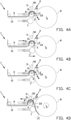
- Figures 4A-4H show a tire building device 1 for forming a tire component (not shown) on a drum 8, in particular a strip-winding drum.
- a continuous length of a strip 9 is wound over a plurality of windings around the drum 8 to form the tire component, i.e. a tread.
- the drum 8 is rotatable about a drum axis D and simultaneously traverses parallel to its drum axis D to receive the plurality of windings in a side-by-side relationship.
- the tire building device 1 comprises a servicer 10, i.e. a conveyor, for supplying the strip 9 towards the drum 8, an applicator unit 2 for applying the strip 9 to the drum 8 and one or more stitching rollers 7 for stitching the strip 9.
- a servicer i.e. a conveyor
- an applicator unit 2 for applying the strip 9 to the drum 8
- one or more stitching rollers 7 for stitching the strip 9.
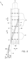
- FIG. 1 shows the applicator unit 2 according to a first exemplary embodiment of the invention in more detail.
- the applicator unit 2 comprises an applicator roller 3 for applying the strip 9 to the drum 8 and a cutter 5 for cutting the strip 9 to length.
- the applicator roller 3 and the cutter 5 are arranged on or mounted to a common structure, frame or base 20.
- the applicator roller 3 comprises a roller body 40 that is rotatable about a roller axis R for applying the strip 9 to the drum 8 in an application direction A perpendicular to said roller axis R.
- the roller body 40 is annular, i.e.
- the roller body 40 has an outwardly facing circumferential surface 41.
- the applicator roller 3 further comprises a plurality of retaining elements 42 distributed in a circumferential direction C about the roller axis R over said roller body 40.
- the plurality of retaining elements 42 are formed by vacuum or suction openings.
- the suction openings are formed as through-holes extending radially through the roller body 40.
- the plurality of retaining elements 42 are distributed over the roller body 40 according to a pattern E, F.
- the pattern comprises a plurality of rows E extending parallel to the roller axis R.
- the plurality of rows E are mutually spaced apart in a circumferential direction C about said roller axis R.
- the retaining elements 42 in each of the rows E of the pattern are also arranged in a plurality of columns F in the circumferential direction C to arrive at a matrix-like pattern.
- each row E comprises at least three retaining elements 42 of the plurality of retaining elements 42.
- the applicator roller 3 further comprises an inner member 30 that is located concentrically within the roller body 40.
- the roller body 40 is rotatable about the inner member 30.
- the roller body 40 is rotatable in both directions, i.e. in the application direction A and in a direction opposite to said application direction A.
- the inner member 30 preferably remains stationary during the rotation of the roller body 40.
- the inner member 30 is in a fixed angular position relative to the roller axis R.
- some means may be provided to adjust or fine-tune the angular position of the inner member 30 about the roller axis R, i.e. with some slots and suitable fasteners.
- the inner member 30 forms, defines and/or comprises a first chamber 31, a second chamber 32 and a third chamber 33 arranged sequentially in the circumferential direction C which are configured or arranged to be in air communication with a first circumferential section S1 and a second circumferential section S2, respectively, of the roller body 40.
- the second chamber 32 is located in a fixed angular position about the roller axis R that corresponds to a blow-off position Z for transferring a leading end LE of the strip 9 to the drum 8.
- the first chamber 31 and the third chamber 33 are located upstream and downstream, respectively, of the second chamber 32 relative to the application direction A.
- the first chamber 31 and the second chamber 32 are separated from each other in the circumferential direction C by a first separation wall 34.
- the second chamber 32 and the third chamber 33 are separated from each other in the circumferential direction C by a second separation wall 35.
- the first chamber 31, the second chamber 32 and the third chamber 33 are individually connectable to a source of compressed air or partial vacuum.
- one or more of the chambers 31-33 can selectively, individually and/or simultaneously generate suction through the suctions openings 42 in the respective circumferential sections S1-S3 of the roller body 40.
- one or more of the chambers 31-33 may selectively, individually and/or simultaneously be connected to a source of compressed air to blow-off the strip 9 from the suctions openings 42 in the respective circumferential sections S1-S3 of the roller body 40.
- the cutter 5 comprises a cutting blade 50.
- the cutting blade 50 is circular or disc-shaped.
- the circular disc blade 50 is rotatable about a cutting blade axis T.
- the cutter 5 further comprises a housing 51 that shields the cutting blade 50 to prevent injuries when the operator is working in close proximity to the cutter. Only the lower part of the cutting blade 50 protrudes out of the housing 51.
- the cutting blade 50 and/or its housing 51 is mounted on a holder 52.
- the holder 52 is movable along a guide rail 53 in a lateral direction L parallel to the roller axis R, thereby allowing the cutting blade 50 to move relative to and/or across the applicator roller 3 in said lateral direction L.
- the holder 52 is designed to hold the cutting blade 50 at a blade angle B that preferably is non-right or oblique relative to a neutral plane N extending radially or perpendicular to the roller axis R.
- the 'blade angle' B is the angle between main surface or the main plane in which the cutting blade B extends and the neutral plane N.
- the blade angle B may correspond to the angle between the cutting blade axis T and the roller axis R.
- the blade angle B may be chosen such that the cutting blade 50 extends at the side of the neutral plane N as shown in figure 1 , or alternatively at the opposite side of the neutral plane N, i.e. to change the orientation of the leading end LE and the trailing end TE.
- the holder 52 is formed as a rigid block with no means to adapt the blade angle B other than replacing the holder 52 with an alternative holder. It is however envisioned that the holder 52 may alternatively be configured for adjusting the blade angle B, i.e. by manually adjustable, mechanical means or via a remotely controlled actuator (not shown).
- FIG 5 shows an alternative applicator unit 102 according to a second exemplary embodiment of the invention that differs from the previously discussed applicator unit 2 in that the blade angle B of the cutting blade 50 is adjustable relative to the holder 152 about an adjustment axis G.
- the cutter 105 comprises a housing 151 that is hingably connected to said holder 152 about an adjustment axis G to set the blade angle B of the cutting blade 50 between the position as shown in solid lines and an opposite position shown in dashed lines.
- the cutter 5 further comprises a cutting height adjustment member 54 to adjust the height of the cutting blade 50 relative to the applicator roller 3.
- the cutting height adjustment member 54 may also allow the cutting blade 50 follow height variations in the circumferential surface 41 of the roller body 40, i.e. when said circumferential surface 41 is slightly crowned.
- the cutting height adjustment member 54 may for example be a pneumatic cylinder that can be compressed slightly when the cutting blade 50 moves across the circumferential surface 41 in the lateral direction L.
- the applicator unit 2 further comprises a rotation drive 21 for rotating the roller body 40 about the roller axis R and a linear or lateral drive 22 for generating a relative displacement between the cutting blade 50 and the applicator roller 3 in the lateral direction L.
- the lateral drive 22 is configured for displacing the cutting blade 50 across the applicator roller 3 in the lateral direction L.
- the lateral drive 22 engages directly onto and/or drives the holder 52.
- the lateral drive 22 may comprises a spindle 23 that can convert a rotation into a linear motion of the cutting blade 50 in or parallel to the lateral direction L.
- the lateral drive may be arranged to displace the applicator roller 3 relative to the cutting blade 50 in the lateral direction L.
- the applicator unit 2 further comprises a control unit 6 that is electronically and/or operationally connected to the rotation drive 21 and the lateral drive 22.
- the control unit 6 is adapted, configured, programmed and/or arranged for controlling the rotation of the roller body 40 about the roller axis R and the relative displacement between the cutting blade 50 and the applicator roller 3 in the lateral direction L.
- the control unit 6 can make the cutting blade 50 move across the circumferential surface 41 of the roller body 40 along a helical cutting path P about the roller axis R, as shown in figures 2 and 3 .
- the helical cutting path P is arranged at an oblique path angle H to the neutral plane N.
- the oblique path angle H is preferably chosen in a range between ten and eighty degrees.
- the strip 9 When cutting through the strip 9 along the helical cutting path P, the strip 9 may adhere to the cutting blade 50 during cutting and can unintentionally be pulled along with the cutting blade 50. This may occur when the material of the strip 9 is relatively soft, tacky or thin.
- the blade angle B may intentionally be offset relative to the helical cutting path P over a relatively small offset angle K.
- the offset angle K is preferably within a range of zero to ten degrees. The offset angle K will allow the material of the strip 9 to come loose from the cutting blade 50 more easily during the cutting.
- the offset may result in the cutting blade 50 extending at a blade angle B of zero or ninety degrees to the neutral plane N.
- the cutting blade 50 may be parallel to the neutral plane N or perpendicular to said neutral plane N, while still moving along the helical cutting path P.
- the blade angle B and the oblique path angle H may be the same, i.e. the cutting blade 50 may be aligned with the helical cutting path P.
- the helical cutting path P starts at an intersection position X where the cutting blade 50 first intersects with the roller body 40 of the applicator roller 3.
- the control unit 6 is configured for determining an angular position of the roller body 40 about the roller axis R, i.e. by using calibration and/or position data from the rotation drive 21 or by using an encoder (not shown). The control unit 6 can use this information to predict and/or predetermine where the intersection point X will be on the circumference of the roller body 40 for a specific start time of the relative displacement between the cutting blade 50 and the applicator roller 3 in the lateral direction L.
- control unit 6 can time the relative displacement in the lateral direction L to control the intersection position X to be at a predetermined location on the circumference of the roller body 40.
- said blade angle B may be set prior to and/or varied during the cutting.
- control unit 6 may time the relative displacement in the lateral direction L relative to the plurality of retaining elements 42 such that the helical cutting path P, starting from said predetermined intersection position X, extends clear off all retaining elements 42 of the plurality of retaining elements 42 that are in close proximity to the helical cutting path P or all retaining elements 42 of the plurality of retaining elements 42 that are located within a circumferential section of the roller body 41 through which the helical cutting path P extends.
- the helical cutting path P extends through four rows E of the plurality of rows E while extending clear of the plurality of retaining elements 42 in said four rows E. It will be appreciated by one skilled in the art that there may be a small tolerance in the timing which would result in alternative helical cutting paths P', P" that would still extend clear of the retaining elements 42 in the respective rows E. Also, the oblique path angle H may differ slightly within the aforementioned tolerance without the helical cutting path P intersecting with any one of the retaining elements 42.
- the first separation wall 34 extends parallel or substantially parallel to the roller axis R and the second separation wall 35 extends parallel or substantially parallel to the helical cutting path P.
- Figure 4A shows the situation in which the strip 9 is supplied by the servicer 10 to the applicator unit 2.
- the cutting blade 50 is retracted into a standby position at the side of and/or above the applicator roller 3.
- the leading end LE has been created by cutting-off a previous length of the strip 9 (not shown) during a previous cycle of the method.
- the leading end LE may be created by cutting-off a waste length of an entirely new strip 9 at the start of the first cycle of the method.
- the leading end LE is positioned on the applicator roller 3 overhead or lying on the circumferential sections associated with the first chamber 31 and the second chamber 32.
- the first chamber 31 and the second chamber 32 are connected to a source of partial vacuum to retain the leading end LE and the body of the strip 8 upstream of said leading end LE, i.e. at the location of said first chamber 31 and said second chamber 32, through suction.
- the third chamber 33 is not pressurized or 'idle' to prevent air leakage through the suction openings not covered by the strip 9.
- the drum 8 is empty and ready to receive windings of the strip 9.
- Figure 4B shows the situation in which the applicator unit 2 is moved towards the drum 1 to apply the leading end LE onto the circumferential surface of the drum 8.
- the first chamber 31 and the second chamber 32 remain under partial vacuum.
- the stitcher roller 7 is moved towards the drum 8 at the same time.
- the stitcher roller 7 may be moved towards the drum 8 after the leading end LE has been applied.
- Figure 4C shows the situation in which the second chamber 32 is switched or disconnected from the source of partial vacuum and is instead connected to a source of compressed air.
- the second chamber 32 is pressurized with a pressure greater than the ambient pressure.
- the suction openings in the roller body of the applicator roller 3 which are in communication with the second chamber 32 can now effectively blow-off the leading end LE, thereby transferring said leading end LE from the applicator roller 3 onto the drum 8.
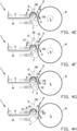
- Figure 4D shows the situation in which the roller body of the applicator roller 3 is rotated at an angular velocity V about the roller axis R to advance and/or transfer the leading end LE of the strip 9 towards the drum 8 in the application direction A.
- the drum 8 is rotated to receive the strip 9 as it is transferred onto the drum 8 by the applicator roller 3.
- the second chamber 32 may be connected to the source of partial vacuum again for together with the first chamber 31 retaining the strip body to the applicator roller 3 along the circumferential sections of associated with said chambers 31, 32. Because the leading end LE has been applied and transferred, the applicator unit 2 may now be retracted in a direction away from the drum 8 so as not to interfere with the operation of the stitching roller 7.
- the cutting blade 50 may be brought into an active position alongside and/or at the level of the circumferential surface of the applicator roller 3, ready for cutting.
- Figure 4E shows the situation in which the drum 8 has been rotated further to take on several or a plurality of windings of the strip 9, i.e. to form one or more layers of a tire component (not shown).
- the applicator roller 3 keeps rotating in the same direction, preferably with the same or a constant angular velocity V.
- the applicator roller 3 and the cutter 5 are simultaneously controlled to move along the helical cutting path, as shown in figure 2 , in the aforementioned manner.
- the method may further comprises the steps of determining the angular position of the roller body about the roller axis R; and timing the previously described relative displacement to control the intersection position X of the helical cutting path P.
- the first chamber 31 and the second chamber 32 remain connected to the source of partial vacuum to reliably retain the strip 9 to the circumferential surface of the applicator roller 3 during the cutting.
- Figure 4F shows the situation when the cutter 5 has completed the cut and the cutting blade 50 is moved away from the circumferential surface of the applicator roller 3.
- the cutting blade 50 is lifted from the applicator roller 3 and returned above the applicator roller 3 to its standby position.
- the cut has generated a new leading end LE and trailing end TE in the strip 9.
- the trailing end TE is part of the cut-off length of the strip 9 that has yet to be transferred onto the drum 8 as part of the final winding to complete the tire component.
- the new leading end LE is ready at the applicator roller 3 for a next cycle of the method.
- the first chamber 31 and the second chamber 32 remain connected to the source of partial vacuum to retain the new leading end LE.
- Figure 4G shows the situation in which applicator roller 3 is rotated further in the same direction, preferably at the same or a constant angular velocity V to supply the trailing end TE of the cut-off length of the strip 9 towards the drum 8.
- V a constant angular velocity
- the new leading end LE of the strip 9 becomes situated overhead or along the circumferential section of the roller body of the applicator roller 3 that is associated with the third chamber 33.
- the third chamber 33 is now also connected to the source of partial vacuum to retain the leading end LE of the strip 9 to effectively the applicator roller 3 at the location of the third chamber 33.
- Figure 4H shows the situation in which the rotation of the roller body of the applicator roller 3 is reversed to retracted the new leading end LE towards the blow-off position Z, i.e. into a position in which the new leading end LE is located overhead or along the circumferential section associated with the second chamber 32.
- the third chamber 33 may now be disconnected again from the source of partial vacuum.
- the winding on the drum 8 has been completed. Consequently, the stitcher roller 7 may be retracted.
- the roller body of the applicator roller 3 may be rotated continuously in the same direction and/or with a constant or substantially constant angular velocity V, thereby allowing the applicator unit 2 to cut the strip 9 while in motion or 'on-the-fly'. This may prevent stretching or other excessive deformations of said leading end LE and trailing end TE prior to, during or after the cutting.
- Figures 6A and 6B show a further alternative applicator unit 202 that differs from the aforementioned applicator units 2, 102 in that the applicator unit 202 further comprises a scraper 255 at one lateral side of the cutting blade 250 in an axial direction along the cutting blade axis T.
- the scraper 255 is positioned along the cutting blade 250 to prevent that the strip 9, which may still be tacky, sticks to a side of the cutting blade 250 and is pulled along with said cutting blade 250 during the rotation thereof.
- the scraper 255 is positioned at the side of the cutting blade 250 where the cutting blade 250 first cuts into the strip 9 such that the tip of the leading end LE that is initially formed is scraped off from the cutting blade 250 and remains on the applicator roller 3.
- the scraper 255 is provided with an at least partially circular scraping body 256 that forms an at least partially circular scraping edge 257 facing towards applicator roller 3.
- the at least partially circular scraping edge 257 extends eccentrically with respect to the cutting blade axis T, favoring the position where the tip of the leading end TE tends to be pulled upward along the cutting blade 250.
- the cutting blade 250 is of the single bevel type, with the bevel at the side of the cutting blade 250 facing away from the scraper 255, in contrast to the double beveled or V-shaped cutting blade 50 of figure 2 .
- the scraper 255 can be positioned as close as possible to the flat side of the cutting blade 250.
Landscapes
- Engineering & Computer Science (AREA)
- Mechanical Engineering (AREA)
- Life Sciences & Earth Sciences (AREA)
- Forests & Forestry (AREA)
- Manufacturing & Machinery (AREA)
- Tyre Moulding (AREA)
- Details Of Cutting Devices (AREA)
Claims (19)
- Aufbringeinheit zum Aufbringen eines Streifens auf eine Trommel, wobei die Aufbringeinheit eine Aufbringwalze und ein Schneidwerkzeug umfasst, wobei die Aufbringwalze einen Walzenkörper umfasst, der um eine Walzenachse drehbar ist, um den Streifen in einer zur Walzenachse senkrechten Aufbringrichtung auf die Trommel aufzubringen, dadurch gekennzeichnet, dass die Aufbringwalze und das Schneidwerkzeug dazu eingerichtet sind, zum Schneiden des Streifens auf der Aufbringwalze entlang einer spiralförmigen Schneidbahn um die Walzenachse zusammenzuarbeiten.
- Aufbringeinheit nach Anspruch 1, wobei die Aufbringwalze eine Vielzahl von Halteelementen umfasst, die über den Walzenkörper verteilt sind,vorzugsweise wobei die Vielzahl von Halteelementen nach einem Muster über den Walzenkörper verteilt sind,noch bevorzugter wobei das Muster eine Vielzahl von Reihen umfasst, die parallel zur Walzenachse und zueinander beabstandet in einer Umfangsrichtung um die Walzenachse verlaufen,am meisten bevorzugt wobei die spiralförmige Schneidbahn durch zwei oder mehr Reihen der Vielzahl von Reihen verläuft, während sie frei von der Vielzahl von Halteelementen in den zwei oder mehr Reihen verläuft.
- Aufbringeinheit nach Anspruch 2, wobei die spiralförmige Schneidbahn in einem schiefen Bahnwinkel zu einer zur Walzenachse senkrechten neutralen Ebene angeordnet ist, wobei der schiefe Bahnwinkel derart gewählt ist, dass die spiralförmige Schneidbahn entlang mindestens eines Umfangsabschnitts des Walzenkörpers frei von allen Halteelementen der Vielzahl von Halteelementen verläuft,
vorzugsweise wobei der schiefe Bahnwinkel zwischen zehn und achtzig Grad beträgt. - Aufbringeinheit nach Anspruch 2 oder 3, wobei die Vielzahl von Halteelementen Ansaugöffnungen umfasst.
- Aufbringeinheit nach Anspruch 3, wobei der Walzenkörper ringförmig ist, wobei die Aufbringwalze ferner ein inneres Element umfasst, das konzentrisch im Walzenkörper positioniert ist, wobei der Walzenkörper um das innere Element drehbar ist, wobei das innere Element umfasst:eine erste Kammer und eine zweite Kammer, die in einer Umfangsrichtung um die Walzenachse aufeinanderfolgend angeordnet sind, um mit einem ersten Umfangsabschnitt beziehungsweise einem zweiten Umfangsabschnitt des Walzenkörpers in Luftverbindung zu stehen; und/odereine dritte Kammer, die zusammen mit der ersten Kammer und der zweiten Kammer in der Umfangsrichtung aufeinanderfolgend angeordnet ist, wobei die dritte Kammer derart angeordnet ist, dass sie in Luftverbindung mit einem dritten Umfangsabschnitt des Walzenkörpers steht,vorzugsweise wobei die erste Kammer und die zweite Kammer in der Umfangsrichtung durch eine erste Trennwand voneinander getrennt sind, wobei die erste Trennwand parallel oder im Wesentlichen parallel zur Walzenachse verläuft, und/oder die zweite Kammer und die dritte Kammer in der Umfangsrichtung durch eine zweite Trennwand voneinander getrennt sind, wobei die zweite Trennwand parallel oder im Wesentlichen parallel zur spiralförmigen Schneidbahn verläuft,noch bevorzugter wobei die erste Kammer, die zweite Kammer und die dritte Kammer einzeln mit einer Druckluft- oder einer Teilvakuumquelle verbunden werden können,am meisten bevorzugt wobei die zweite Kammer in einer festen Winkelposition um die Walzenachse positioniert ist, die einer Wegblasposition zum Übertragen eines vorderen Endes des Streifens auf die Trommel entspricht, wobei die erste Kammer und die dritte Kammer stromaufwärts beziehungsweise stromabwärts der zweiten Kammer relativ zur Aufbringrichtung positioniert sind.
- Aufbringeinheit nach einem der vorhergehenden Ansprüche, wobei das Schneidwerkzeug eine Schneidklinge umfasst,vorzugsweise wobei die Schneidklinge in einem Klingenwinkel angeordnet ist, der schräg zu einer zur Walzenachse senkrechten neutralen Ebene ist,noch bevorzugter wobei die Schneidklinge in einem Klingenwinkel zu einer zur Walzenachse senkrechten neutralen Ebene angeordnet ist, wobei der Klingenwinkel um eine Einstellachse einstellbar ist, die parallel zur neutralen Ebene ist oder in ihr liegt.
- Aufbringeinheit nach Anspruch 6, wobei die Aufbringeinheit einen Drehantrieb zum Drehen des Walzenkörpers um die Walzenachse und einen Querantrieb zum Erzeugen einer Relativverschiebung zwischen der Schneidklinge und der Aufbringwalze in einer zur Walzenachse parallelen seitlichen Richtung umfasst,
vorzugsweise wobei der Querantrieb dazu eingerichtet ist, die Schneidklinge in der seitlichen Richtung über die Aufbringwalze zu verschieben. - Aufbringeinheit nach Anspruch 7, wobei die Aufbringeinheit ferner eine Steuereinheit umfasst, die betriebsfähig mit dem Drehantrieb und dem Querantrieb verbunden ist, um die Drehung des Walzenkörpers um die Walzenachse und die Relativverschiebung in der seitlichen Richtung zwischen der Schneidklinge und der Aufbringwalze zu steuern,
vorzugsweise wobei die Steuereinheit dazu eingerichtet ist, die Drehung des Walzenkörpers um die Walzenachse und die Relativverschiebung in der seitlichen Richtung zwischen der Schneidklinge und der Aufbringwalze derart zu steuern, dass sich die Schneidklinge entlang der spiralförmigen Schneidbahn bewegt. - Aufbringeinheit nach Anspruch 8, wobeidie Aufbringwalze eine Vielzahl von Halteelementen umfasst, die über den Walzenkörper verteilt sind, wobei die Steuereinheit dazu eingerichtet ist, eine Winkelposition des Walzenkörpers um die Walzenachse zu bestimmen und die Relativverschiebung in der seitlichen Richtung zwischen der Schneidklinge und der Aufbringwalze auf der Grundlage der Winkelposition des Walzenkörpers derart zeitlich zu steuern, dass sich die Schneidklinge, die sich entlang der spiralförmigen Schneidbahn bewegt, zuerst mit dem Walzenkörper an einer vorgegebenen Überkreuzungsposition relativ zur Vielzahl von Halteelementen überkreuzt,vorzugsweise wobei die spiralförmige Schneidbahn, ausgehend von der vorgegebenen Überkreuzungsposition, frei von allen Halteelementen der Vielzahl von Halteelementen verläuft.
- Aufbringeinheit nach Anspruch 8 oder 9, wobei die Steuereinheit dazu eingerichtet ist, den Walzenkörper vor der Relativverschiebung in der seitlichen Richtung zwischen der Schneidklinge und der Aufbringwalze zu drehen und den Walzenkörper während der Relativverschiebung in der seitlichen Richtung zwischen der Schneidklinge und der Aufbringwalze weiterhin zu drehen,
vorzugsweise wobei die Steuereinheit dazu eingerichtet ist, den Walzenkörper mit einer konstanten Winkelgeschwindigkeit vor und während der Relativverschiebung in der seitlichen Richtung zwischen der Schneidklinge und der Aufbringwalze zu drehen. - Aufbringeinheit nach einem der Ansprüche 6 bis 10, wobei der Klingenwinkel von der spiralförmigen Schneidbahn um einen Versatzwinkel in einem Bereich von null bis zehn Grad versetzt ist.
- Reifenaufbauvorrichtung, umfassend die Aufbringeinheit nach einem der vorhergehenden Ansprüche, wobei die Reifenaufbauvorrichtung ferner eine Trommel, insbesondere eine Streifenwickeltrommel, zum Aufnehmen von Wicklungen des Streifens umfasst.
- Verfahren zum Aufbringen eines Streifens auf eine Trommel unter Verwendung einer Aufbringwalze mit einem Walzenkörper, der um eine Walzenachse drehbar ist, wobei das Verfahren dadurch gekennzeichnet ist, dass es den folgenden Schritt umfasst:- Schneiden des Streifens auf der Aufbringwalze entlang einer spiralförmigen Schneidbahn um die Walzenachse.
- Verfahren nach Anspruch 13, wobei die Aufbringwalze eine Vielzahl von Halteelementen umfasst, die über den Walzenkörper verteilt sind, wobei die spiralförmige Schneidbahn in einem schiefen Bahnwinkel zu einer zur Walzenachse senkrechten neutralen Ebene angeordnet ist, wobei der schiefe Bahnwinkel derart gewählt ist, dass die spiralförmige Schneidbahn entlang mindestens eines Umfangsabschnitts des Walzenkörpers frei von allen Halteelementen der Vielzahl von Halteelementen verläuft.
- Verfahren nach Anspruch 13 oder 14, wobei das Verfahren ferner den folgenden Schritt umfasst:- Drehen des Walzenkörpers vor dem Schritt des Schneidens des Streifens auf der Aufbringwalze entlang der spiralförmigen Schneidbahn; und- Fortsetzen des Drehens des Walzenkörpers während des Schritts des Schneidens des Streifens auf der Aufbringwalze entlang der spiralförmigen Schneidbahn,vorzugsweise wobei das Verfahren ferner den Schritt des Drehens des Walzenkörpers mit einer konstanten Winkelgeschwindigkeit vor und während des Schritts des Schneidens des Streifens auf der Aufbringwalze entlang der spiralförmigen Schneidbahn umfasst.
- Verfahren zum Aufbringen eines Streifens auf eine Trommel unter Verwendung einer Aufbringeinheit nach einem der Ansprüche 1 bis 11, wobei das Verfahren die folgenden Schritte umfasst:- Schneiden des Streifens auf der Aufbringwalze entlang der spiralförmigen Schneidbahn.
- Verfahren nach Anspruch 16, wobei das Schneidwerkzeug eine Schneidklinge umfasst, wobei das Verfahren den Schritt des Erzeugens einer Relativverschiebung zwischen der Schneidklinge und der Aufbringwalze in einer seitlichen Richtung parallel zur Walzenachse umfasst, während gleichzeitig der Walzenkörper derart um die Walzenachse gedreht wird, dass sich die Schneidklinge entlang der spiralförmigen Schneidbahn bewegt,
vorzugsweise wobei das Verfahren den Schritt des Verschiebens der Schneidklinge in der seitlichen Richtung über die Aufbringwalze umfasst. - Verfahren nach Anspruch 17, wobei die Aufbringwalze eine Vielzahl von Halteelementen umfasst, die über den Walzenkörper verteilt sind, wobei das Verfahren ferner die folgenden Schritte umfasst:- Bestimmen einer Winkelposition des Walzenkörpers um die Walzenachse; und- zeitliches Steuern der Relativverschiebung in der seitlichen Richtung zwischen der Schneidklinge und der Aufbringwalze auf der Grundlage der Winkelposition des Walzenkörpers derart, dass sich die Schneidklinge, die sich entlang der spiralförmigen Schneidbahn bewegt, zuerst mit dem Walzenkörper an einer vorgegebenen Überkreuzungsposition relativ zur Vielzahl von Halteelementen überkreuzt,vorzugsweise wobei die spiralförmige Schneidbahn, ausgehend von der vorgegebenen Überkreuzungsposition, frei von allen Halteelementen der Vielzahl von Halteelementen verläuft.
- Verfahren nach einem der Ansprüche 16 bis 18, wobei der Walzenkörper ringförmig ist, wobei die Aufbringwalze ferner ein inneres Element umfasst, das konzentrisch im Walzenkörper positioniert ist, wobei das innere Element eine erste Kammer und eine zweite Kammer umfasst, die in einer Umfangsrichtung um die Walzenachse aufeinanderfolgend angeordnet sind, um mit einem ersten Umfangsabschnitt beziehungsweise einem zweiten Umfangsabschnitt des Walzenkörpers in Luftverbindung zu stehen, wobei das Verfahren ferner den folgenden Schritt umfasst:- Drehen des Walzenkörpers um das innere Element,vorzugsweise wobei das innere Element eine dritte Kammer umfasst, die zusammen mit der ersten Kammer und der zweiten Kammer in der Umfangsrichtung aufeinanderfolgend angeordnet ist, wobei die dritte Kammer derart angeordnet ist, dass sie in Luftverbindung mit einem dritten Umfangsabschnitt des Walzenkörpers steht, wobei das Verfahren ferner den folgenden Schritt umfasst:- einzelnes Verbinden der ersten Kammer, der zweiten Kammer und der dritten Kammer mit einer Druckluft- oder einer Teilvakuumquelle,noch bevorzugter wobei die zweite Kammer in einer festen Winkelposition um die Walzenachse positioniert ist, die einer Wegblasposition zum Übertragen eines vorderen Endes des Streifens auf die Trommel entspricht, wobei die erste Kammer und die dritte Kammer stromaufwärts beziehungsweise stromabwärts der zweiten Kammer relativ zur Aufbringrichtung positioniert sind, wobei das Verfahren ferner die folgenden Schritte umfasst:- Verbinden von mindestens einer von der ersten Kammer und der zweiten Kammer mit einer Teilvakuumquelle, um den Streifen während des Schritts des Schneidens des Streifens auf der Aufbringwalze entlang der spiralförmigen Schneidbahn festzuhalten;- Verbinden der dritten Kammer mit einer Teilvakuumquelle, um das vordere Ende des Streifens nach dem Schneiden festzuhalten; und- Trennen der dritten Kammer von der Teilvakuumquelle und Verbinden der zweiten Kammer mit einer Druckluftquelle, um das vordere Ende wegzublasen,am meisten bevorzugt wobei das Verfahren ferner den Schritt des Umkehrens der Drehung des Walzenkörpers vor dem Schritt des Trennens der dritten Kammer von der Teilvakuumquelle und des Verbindens der zweiten Kammer mit der Druckluftquelle zum Wegblasen des vorderen Endes umfasst.
Priority Applications (1)
| Application Number | Priority Date | Filing Date | Title |
|---|---|---|---|
| RS20250515A RS66836B1 (sr) | 2021-02-16 | 2022-02-03 | Jedinica za nanošenje, uređaj za izradu pneumatika i postupak za nanošenje trake na bubanj |
Applications Claiming Priority (2)
| Application Number | Priority Date | Filing Date | Title |
|---|---|---|---|
| NL2027569A NL2027569B1 (en) | 2021-02-16 | 2021-02-16 | Applicator unit, tire building device and method for applying a strip to a drum |
| PCT/NL2022/050051 WO2022177421A1 (en) | 2021-02-16 | 2022-02-03 | Applicator unit, tire building device and method for applying a strip to a drum |
Publications (3)
| Publication Number | Publication Date |
|---|---|
| EP4294608A1 EP4294608A1 (de) | 2023-12-27 |
| EP4294608C0 EP4294608C0 (de) | 2025-03-19 |
| EP4294608B1 true EP4294608B1 (de) | 2025-03-19 |
Family
ID=76159877
Family Applications (1)
| Application Number | Title | Priority Date | Filing Date |
|---|---|---|---|
| EP22703728.0A Active EP4294608B1 (de) | 2021-02-16 | 2022-02-03 | Aufbringvorrichtung, reifenaufbauvorrichtung und verfarhen zum auftragen von streifen auf eine trommel |
Country Status (14)
| Country | Link |
|---|---|
| US (1) | US20240227229A9 (de) |
| EP (1) | EP4294608B1 (de) |
| JP (1) | JP7547475B2 (de) |
| KR (1) | KR20230146601A (de) |
| CN (4) | CN219634594U (de) |
| CA (1) | CA3207336A1 (de) |
| ES (1) | ES3015756T3 (de) |
| HU (1) | HUE071277T2 (de) |
| MX (1) | MX2023009577A (de) |
| NL (1) | NL2027569B1 (de) |
| PL (1) | PL4294608T3 (de) |
| RS (1) | RS66836B1 (de) |
| TW (1) | TW202315739A (de) |
| WO (1) | WO2022177421A1 (de) |
Families Citing this family (2)
| Publication number | Priority date | Publication date | Assignee | Title |
|---|---|---|---|---|
| NL2027569B1 (en) * | 2021-02-16 | 2022-09-14 | Vmi Holland Bv | Applicator unit, tire building device and method for applying a strip to a drum |
| NL2034576B1 (en) * | 2023-04-14 | 2024-10-21 | Vmi Holland Bv | Applicator unit, tire building device and method for applying a continuous strip to a drum |
Family Cites Families (12)
| Publication number | Priority date | Publication date | Assignee | Title |
|---|---|---|---|---|
| US1938787A (en) * | 1928-03-15 | 1933-12-12 | Morgan And Wright | Process and apparatus for manufacturing tires |
| BE791742A (fr) * | 1971-11-26 | 1973-05-22 | Uniroyal Inc | Appareil de coupe a longueur pour matiere decoupee en biais pour nappesde ceinture d'enveloppe de bandage pneumatique de roue |
| US4247349A (en) * | 1979-05-14 | 1981-01-27 | American Can Company | Method and apparatus for cutting plastic film windows for cartons |
| WO1981000691A1 (en) | 1979-09-11 | 1981-03-19 | Caterpillar Tractor Co | Tape brake for tape wrapper |
| JPH054293A (ja) * | 1990-10-20 | 1993-01-14 | Sumitomo Rubber Ind Ltd | 生タイヤの製造方法及びその装置 |
| US6790301B2 (en) * | 2001-10-15 | 2004-09-14 | The Goodyear Tire And Rubber Company | Method and apparatus for making a tread-belt assembly |
| JP4132904B2 (ja) | 2002-03-20 | 2008-08-13 | グンゼ株式会社 | タブテープ貼付ヘッド及びタブテープ貼付装置 |
| DE102009035269A1 (de) * | 2009-07-29 | 2011-02-03 | Krones Ag | Schneideinrichtung und Schneidverfahren zum Schneiden von Etiketten sowie Etikettiervorrichtung |
| NL2017819B1 (en) * | 2016-11-18 | 2018-05-25 | Vmi Holland Bv | Cutting device and method for a continuous strip into tire components |
| SE542363C2 (en) * | 2017-02-22 | 2020-04-14 | Core Link Ab | Method and apparatus for removing wrapping from rolls |
| JP6765996B2 (ja) | 2017-03-09 | 2020-10-07 | Toyo Tire株式会社 | ゴム部材の製造方法及び製造装置 |
| NL2027569B1 (en) * | 2021-02-16 | 2022-09-14 | Vmi Holland Bv | Applicator unit, tire building device and method for applying a strip to a drum |
-
2021
- 2021-02-16 NL NL2027569A patent/NL2027569B1/en active
-
2022
- 2022-02-03 MX MX2023009577A patent/MX2023009577A/es unknown
- 2022-02-03 US US18/546,630 patent/US20240227229A9/en active Pending
- 2022-02-03 CA CA3207336A patent/CA3207336A1/en active Pending
- 2022-02-03 EP EP22703728.0A patent/EP4294608B1/de active Active
- 2022-02-03 ES ES22703728T patent/ES3015756T3/es active Active
- 2022-02-03 JP JP2022520231A patent/JP7547475B2/ja active Active
- 2022-02-03 KR KR1020237031486A patent/KR20230146601A/ko active Pending
- 2022-02-03 RS RS20250515A patent/RS66836B1/sr unknown
- 2022-02-03 HU HUE22703728A patent/HUE071277T2/hu unknown
- 2022-02-03 PL PL22703728.0T patent/PL4294608T3/pl unknown
- 2022-02-03 WO PCT/NL2022/050051 patent/WO2022177421A1/en not_active Ceased
- 2022-02-08 TW TW111104547A patent/TW202315739A/zh unknown
- 2022-02-16 CN CN202320059550.5U patent/CN219634594U/zh active Active
- 2022-02-16 CN CN202320059461.0U patent/CN219325555U/zh active Active
- 2022-02-16 CN CN202210142946.6A patent/CN114953552A/zh active Pending
- 2022-02-16 CN CN202220315375.7U patent/CN218430103U/zh active Active
Also Published As
| Publication number | Publication date |
|---|---|
| WO2022177421A1 (en) | 2022-08-25 |
| NL2027569A (en) | 2022-09-14 |
| ES3015756T3 (en) | 2025-05-07 |
| NL2027569B1 (en) | 2022-09-14 |
| JP2023517261A (ja) | 2023-04-25 |
| RS66836B1 (sr) | 2025-06-30 |
| US20240131742A1 (en) | 2024-04-25 |
| EP4294608C0 (de) | 2025-03-19 |
| TW202315739A (zh) | 2023-04-16 |
| CN114953552A (zh) | 2022-08-30 |
| PL4294608T3 (pl) | 2025-07-07 |
| KR20230146601A (ko) | 2023-10-19 |
| CN219325555U (zh) | 2023-07-11 |
| US20240227229A9 (en) | 2024-07-11 |
| MX2023009577A (es) | 2023-08-23 |
| JP7547475B2 (ja) | 2024-09-09 |
| CN218430103U (zh) | 2023-02-03 |
| HUE071277T2 (hu) | 2025-08-28 |
| CN219634594U (zh) | 2023-09-05 |
| EP4294608A1 (de) | 2023-12-27 |
| CA3207336A1 (en) | 2022-08-25 |
Similar Documents
| Publication | Publication Date | Title |
|---|---|---|
| EP4294608B1 (de) | Aufbringvorrichtung, reifenaufbauvorrichtung und verfarhen zum auftragen von streifen auf eine trommel | |
| CN100411863C (zh) | 组装车轮轮胎的方法和设备 | |
| US5354404A (en) | Control for integrated tire building system | |
| US7118642B2 (en) | Method and plant for the manufacture of green tyres | |
| EP3177457B1 (de) | Vorrichtung und verfahren zur herstellung von reifen für fahrzeugräder | |
| WO2004037524A1 (ja) | タイヤの製造方法、この製造方法に用いられるカバーゴム貼付装置、およびタイヤ、ならびに、ゴムシート部材の貼付け方法およびゴムシート部材貼付装置 | |
| CN113039061A (zh) | 使用螺旋刀具切割带材的系统及相应的切割方法 | |
| EP1560698B1 (de) | Verfahren und vorrichtung zum aufbauen eines fahrzeugreifens | |
| JP4205055B2 (ja) | タイヤ構成部材の貼着装置および貼着方法 | |
| EP1279485B1 (de) | Verfahren zur Herstellung eines Luftreifens aufweisend eine kordverstärkte Schicht | |
| CN100469562C (zh) | 用于制造车轮轮胎的方法和设备 | |
| EP1238788B1 (de) | Vorrichtung zur herstellung von radialreifen | |
| US20130319617A1 (en) | Process and apparatus for manufacturing tyres for vehicle wheels | |
| KR102670797B1 (ko) | 비드-에이펙스 스티칭 장치 및 비드에 에이펙스를 스티칭하는 방법 | |
| RU2603166C2 (ru) | Способ и установка для сборки шин для колес транспортных средств | |
| CN224183824U (zh) | 用于将轮胎部件施加到轮胎成型鼓的施加器 | |
| US20030019565A1 (en) | Apparatus and method for manufacturing a tire reinforcement | |
| US20080314524A1 (en) | Method for single line tire ply construction | |
| JPH0137262B2 (de) |
Legal Events
| Date | Code | Title | Description |
|---|---|---|---|
| STAA | Information on the status of an ep patent application or granted ep patent |
Free format text: STATUS: UNKNOWN |
|
| STAA | Information on the status of an ep patent application or granted ep patent |
Free format text: STATUS: THE INTERNATIONAL PUBLICATION HAS BEEN MADE |
|
| PUAI | Public reference made under article 153(3) epc to a published international application that has entered the european phase |
Free format text: ORIGINAL CODE: 0009012 |
|
| STAA | Information on the status of an ep patent application or granted ep patent |
Free format text: STATUS: REQUEST FOR EXAMINATION WAS MADE |
|
| 17P | Request for examination filed |
Effective date: 20230713 |
|
| AK | Designated contracting states |
Kind code of ref document: A1 Designated state(s): AL AT BE BG CH CY CZ DE DK EE ES FI FR GB GR HR HU IE IS IT LI LT LU LV MC MK MT NL NO PL PT RO RS SE SI SK SM TR |
|
| DAV | Request for validation of the european patent (deleted) | ||
| DAX | Request for extension of the european patent (deleted) | ||
| REG | Reference to a national code |
Ref country code: DE Ref legal event code: R079 Free format text: PREVIOUS MAIN CLASS: B26D0001157000 Ipc: B29D0030460000 Ref country code: DE Ref legal event code: R079 Ref document number: 602022011970 Country of ref document: DE Free format text: PREVIOUS MAIN CLASS: B26D0001157000 Ipc: B29D0030460000 |
|
| GRAP | Despatch of communication of intention to grant a patent |
Free format text: ORIGINAL CODE: EPIDOSNIGR1 |
|
| STAA | Information on the status of an ep patent application or granted ep patent |
Free format text: STATUS: GRANT OF PATENT IS INTENDED |
|
| RIC1 | Information provided on ipc code assigned before grant |
Ipc: B26D 1/157 20060101ALI20240911BHEP Ipc: B26D 7/26 20060101ALI20240911BHEP Ipc: B26D 7/20 20060101ALI20240911BHEP Ipc: B26D 7/01 20060101ALI20240911BHEP Ipc: B26D 1/18 20060101ALI20240911BHEP Ipc: B26D 1/16 20060101ALI20240911BHEP Ipc: B29D 30/30 20060101ALI20240911BHEP Ipc: B29D 30/46 20060101AFI20240911BHEP |
|
| INTG | Intention to grant announced |
Effective date: 20240926 |
|
| GRAS | Grant fee paid |
Free format text: ORIGINAL CODE: EPIDOSNIGR3 |
|
| GRAA | (expected) grant |
Free format text: ORIGINAL CODE: 0009210 |
|
| STAA | Information on the status of an ep patent application or granted ep patent |
Free format text: STATUS: THE PATENT HAS BEEN GRANTED |
|
| AK | Designated contracting states |
Kind code of ref document: B1 Designated state(s): AL AT BE BG CH CY CZ DE DK EE ES FI FR GB GR HR HU IE IS IT LI LT LU LV MC MK MT NL NO PL PT RO RS SE SI SK SM TR |
|
| REG | Reference to a national code |
Ref country code: GB Ref legal event code: FG4D |
|
| REG | Reference to a national code |
Ref country code: CH Ref legal event code: EP |
|
| REG | Reference to a national code |
Ref country code: IE Ref legal event code: FG4D |
|
| REG | Reference to a national code |
Ref country code: DE Ref legal event code: R096 Ref document number: 602022011970 Country of ref document: DE |
|
| U01 | Request for unitary effect filed |
Effective date: 20250402 |
|
| U07 | Unitary effect registered |
Designated state(s): AT BE BG DE DK EE FI FR IT LT LU LV MT NL PT RO SE SI Effective date: 20250409 |
|
| PG25 | Lapsed in a contracting state [announced via postgrant information from national office to epo] |
Ref country code: NO Free format text: LAPSE BECAUSE OF FAILURE TO SUBMIT A TRANSLATION OF THE DESCRIPTION OR TO PAY THE FEE WITHIN THE PRESCRIBED TIME-LIMIT Effective date: 20250619 |
|
| PG25 | Lapsed in a contracting state [announced via postgrant information from national office to epo] |
Ref country code: HR Free format text: LAPSE BECAUSE OF FAILURE TO SUBMIT A TRANSLATION OF THE DESCRIPTION OR TO PAY THE FEE WITHIN THE PRESCRIBED TIME-LIMIT Effective date: 20250319 |
|
| REG | Reference to a national code |
Ref country code: SK Ref legal event code: T3 Ref document number: E 46469 Country of ref document: SK |
|
| PG25 | Lapsed in a contracting state [announced via postgrant information from national office to epo] |
Ref country code: GR Free format text: LAPSE BECAUSE OF FAILURE TO SUBMIT A TRANSLATION OF THE DESCRIPTION OR TO PAY THE FEE WITHIN THE PRESCRIBED TIME-LIMIT Effective date: 20250620 |
|
| REG | Reference to a national code |
Ref country code: HU Ref legal event code: AG4A Ref document number: E071277 Country of ref document: HU |
|
| PG25 | Lapsed in a contracting state [announced via postgrant information from national office to epo] |
Ref country code: SM Free format text: LAPSE BECAUSE OF FAILURE TO SUBMIT A TRANSLATION OF THE DESCRIPTION OR TO PAY THE FEE WITHIN THE PRESCRIBED TIME-LIMIT Effective date: 20250319 |
|
| PG25 | Lapsed in a contracting state [announced via postgrant information from national office to epo] |
Ref country code: IS Free format text: LAPSE BECAUSE OF FAILURE TO SUBMIT A TRANSLATION OF THE DESCRIPTION OR TO PAY THE FEE WITHIN THE PRESCRIBED TIME-LIMIT Effective date: 20250719 |
|
| PLBE | No opposition filed within time limit |
Free format text: ORIGINAL CODE: 0009261 |
|
| STAA | Information on the status of an ep patent application or granted ep patent |
Free format text: STATUS: NO OPPOSITION FILED WITHIN TIME LIMIT |
|
| REG | Reference to a national code |
Ref country code: CH Ref legal event code: L10 Free format text: ST27 STATUS EVENT CODE: U-0-0-L10-L00 (AS PROVIDED BY THE NATIONAL OFFICE) Effective date: 20260128 |
|
| 26N | No opposition filed |
Effective date: 20251222 |
|
| PGFP | Annual fee paid to national office [announced via postgrant information from national office to epo] |
Ref country code: HU Payment date: 20260220 Year of fee payment: 5 |
|
| U20 | Renewal fee for the european patent with unitary effect paid |
Year of fee payment: 5 Effective date: 20260225 |
|
| PGFP | Annual fee paid to national office [announced via postgrant information from national office to epo] |
Ref country code: RS Payment date: 20260123 Year of fee payment: 5 |
|
| PGFP | Annual fee paid to national office [announced via postgrant information from national office to epo] |
Ref country code: TR Payment date: 20260128 Year of fee payment: 5 |