EP4373659B1 - Versorgungsvorrichtung für zwei reifenkomponenten und verfahren zur versorgung einer reifenaufbautrommel mit zwei reifenkomponenten - Google Patents
Versorgungsvorrichtung für zwei reifenkomponenten und verfahren zur versorgung einer reifenaufbautrommel mit zwei reifenkomponenten Download PDFInfo
- Publication number
- EP4373659B1 EP4373659B1 EP22735639.1A EP22735639A EP4373659B1 EP 4373659 B1 EP4373659 B1 EP 4373659B1 EP 22735639 A EP22735639 A EP 22735639A EP 4373659 B1 EP4373659 B1 EP 4373659B1
- Authority
- EP
- European Patent Office
- Prior art keywords
- pick
- tire component
- unit
- place
- tire
- Prior art date
- Legal status (The legal status is an assumption and is not a legal conclusion. Google has not performed a legal analysis and makes no representation as to the accuracy of the status listed.)
- Active
Links
Images


Classifications
-
- B—PERFORMING OPERATIONS; TRANSPORTING
- B29—WORKING OF PLASTICS; WORKING OF SUBSTANCES IN A PLASTIC STATE IN GENERAL
- B29D—PRODUCING PARTICULAR ARTICLES FROM PLASTICS OR FROM SUBSTANCES IN A PLASTIC STATE
- B29D30/00—Producing pneumatic or solid tyres or parts thereof
- B29D30/06—Pneumatic tyres or parts thereof (e.g. produced by casting, moulding, compression moulding, injection moulding, centrifugal casting)
- B29D30/08—Building tyres
- B29D30/20—Building tyres by the flat-tyre method, i.e. building on cylindrical drums
- B29D30/24—Drums
- B29D30/26—Accessories or details, e.g. membranes, transfer rings
-
- B—PERFORMING OPERATIONS; TRANSPORTING
- B29—WORKING OF PLASTICS; WORKING OF SUBSTANCES IN A PLASTIC STATE IN GENERAL
- B29D—PRODUCING PARTICULAR ARTICLES FROM PLASTICS OR FROM SUBSTANCES IN A PLASTIC STATE
- B29D30/00—Producing pneumatic or solid tyres or parts thereof
- B29D30/06—Pneumatic tyres or parts thereof (e.g. produced by casting, moulding, compression moulding, injection moulding, centrifugal casting)
- B29D30/08—Building tyres
- B29D30/20—Building tyres by the flat-tyre method, i.e. building on cylindrical drums
- B29D30/30—Applying the layers; Guiding or stretching the layers during application
- B29D30/3007—Applying the layers; Guiding or stretching the layers during application by feeding a sheet perpendicular to the drum axis and joining the ends to form an annular element
-
- B—PERFORMING OPERATIONS; TRANSPORTING
- B29—WORKING OF PLASTICS; WORKING OF SUBSTANCES IN A PLASTIC STATE IN GENERAL
- B29D—PRODUCING PARTICULAR ARTICLES FROM PLASTICS OR FROM SUBSTANCES IN A PLASTIC STATE
- B29D30/00—Producing pneumatic or solid tyres or parts thereof
- B29D30/06—Pneumatic tyres or parts thereof (e.g. produced by casting, moulding, compression moulding, injection moulding, centrifugal casting)
- B29D30/08—Building tyres
- B29D30/20—Building tyres by the flat-tyre method, i.e. building on cylindrical drums
- B29D30/30—Applying the layers; Guiding or stretching the layers during application
- B29D30/3042—Applying the layers; Guiding or stretching the layers during application by feeding cut-to-length pieces in a direction perpendicular to the drum axis and in a plane parallel to the drum axis, and placing the pieces side-by-side to form an annular element
-
- B—PERFORMING OPERATIONS; TRANSPORTING
- B29—WORKING OF PLASTICS; WORKING OF SUBSTANCES IN A PLASTIC STATE IN GENERAL
- B29D—PRODUCING PARTICULAR ARTICLES FROM PLASTICS OR FROM SUBSTANCES IN A PLASTIC STATE
- B29D30/00—Producing pneumatic or solid tyres or parts thereof
- B29D30/06—Pneumatic tyres or parts thereof (e.g. produced by casting, moulding, compression moulding, injection moulding, centrifugal casting)
- B29D30/08—Building tyres
- B29D30/20—Building tyres by the flat-tyre method, i.e. building on cylindrical drums
- B29D30/30—Applying the layers; Guiding or stretching the layers during application
- B29D2030/3064—Details, accessories and auxiliary operations not otherwise provided for
- B29D2030/3085—Details, accessories and auxiliary operations not otherwise provided for the layers being applied being already cut to the appropriate length, before the application step
Definitions
- the invention relates to a dual tire component servicer and a method for supplying dual tire components to a tire building drum.
- a known dual tire component servicer for supply breaker cushions to a tire building drum comprises two conveyors for simultaneously conveying two breaker cushions in a supply direction towards the tire building drum and two pick-and-place units for synchronously transferring the two breaker cushions from their respective conveyors to the tire building drum. Examples for such tire component servicers are disclosed in the patent appplications WO 2020255555 A1 and WO 2020255556 A1 .
- the lateral positions of the pick-and-place units are manually adjusted and aligned visually by a human operator to match the lateral position of the leading ends of the breaker cushions on the conveyors, prior to transfer of said breaker cushions to the tire building drum.
- the lateral positions of the pick-and-place units are then fixed prior to transferring of the breaker cushions, to ensure that the pick-and-place units are moved synchronously in the supply direction, without relative movements in the lateral direction.
- a disadvantage of the known dual tire component servicer is that the lateral positions of the leading and trailing end of the tire components may still shift after cutting due to relaxation or tension inside the material of the tire components. Moreover, the lateral position of the trailing end may not be exactly aligned with the lateral position of the leading end of the same tire component. This is especially true for breaker cushion which, unlike other types of tire components, are not provided with embedded reinforcement cords. As such, breaker cushions are particularly susceptible to lateral shifts and deformations.
- the lateral positions of the two tire components may not be offset in the same direction or to the same extent.
- the trailing end may not be accurately spliced to the leading end, thereby negatively impacting the overall quality of the tire.
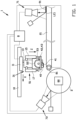
- the invention provides a dual tire component servicer for supplying a first tire component and a second tire component to a tire building drum, wherein the dual tire component servicer comprises a first conveyor and a second conveyor for conveying the first tire component and the second tire component, respectively, in a supply direction towards the tire building drum, wherein the dual tire component servicer further comprises a first pick-and-place unit and a second pick-and-place unit for transferring the first tire component and the second tire component, respectively, from their respective conveyors to the tire building drum, wherein the first pick-and-place unit and the second pick-and-place unit are automatically and independently movable relative to each other in a lateral direction perpendicular to the supply direction.
- the dual tire component servicer comprises a first conveyor and a second conveyor for conveying the first tire component and the second tire component, respectively, in a supply direction towards the tire building drum
- the dual tire component servicer further comprises a first pick-and-place unit and a second pick-and-place unit for transferring the first tire component
- the positions of the tire components in the lateral direction can be adjusted or corrected independently for each tire component during the transfer of the respective tire component.
- one pick-and-place unit may be moved laterally in one of the lateral directions while the other pick-and-place unit is moved in the opposite lateral direction, to a different extent or is not moved at all.
- the lateral positions of the tire components can be adjusted or corrected individually for optimal splicing of the respective trailing ends to the respective leading ends, thereby improving the overall quality of the tire to be build.
- the term 'automatically' is to be interpreted as a movement of the pick-and-place units by themselves, i.e. with no direct human control.
- the dual tire component servicer comprises a first lateral drive and a second lateral drive that are individually controllable for driving the movements of the first pick-and-place unit and the second pick-and-place unit, respectively, in the lateral direction.
- the lateral drives can automatically and independently drive the lateral movements of the respective pick-and-place units, thereby automating said lateral movements.
- first pick-and-place unit and the second pick-and-place unit are synchronously movable in the supply direction.
- the dual tire component servicer may for example comprise a supply drive common to the first pick-and-place unit and the second pick-and-place unit for synchronously driving the movements of the pick-and-place units in the supply direction. Hence, only one supply drive is required to synchronously move both pick-and-place units.
- the dual tire component servicer further comprises a first sensor unit upstream of the first pick-and-place unit and the second pick-and-place unit relative to the supply direction for detecting lateral positions of the first tire component and the second tire component on the first conveyor and the second conveyor, respectively.
- the first sensor unit can be used to correct the lateral positions of the tire components based on detection signals obtained upstream of the tire building drum, i.e. based on the lateral positions of the tire components on the respective conveyors.
- the dual tire component servicer is provided with a control unit that is operationally connected to the first lateral drive, the second lateral drive and the first sensor unit for controlling the movements of the pick-and-place units in the lateral direction based on detection signals from the first sensor unit.
- the movements of the pick-and-place units can be fully automated and/or controlled autonomously by the control unit.
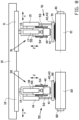
- the push-off plate is movable between a retracted position at the same level as or above the retaining element in the pick-and-place direction and a push-off position below the retaining element in the pick-and-place direction.
- the push-off plate can thus generate a physical distance or spacing between the tire component and the retaining element, thereby effectively bring the tire component out of the effective range of the retaining element.
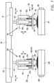
- the first pressing unit and the second pressing unit are carried by the first pick-and-place unit and the second pick-and-place unit, respectively.
- the pressing units can be moved in the lateral direction and the supply direction together with the pick-and-place units.
- the first pressing unit and the second pressing unit are movable in a pick-and-place direction transverse or perpendicular to the supply direction and the lateral direction relative to the first pick-and-place unit and the second pick-and-place unit, respectively.
- the pressing units can be brought into contact with the tire components in a pressing position below or protruding below the pick-and-place units in the pick-and-place direction.
- each pressing unit comprises a first pressing wheel that is rotatable about a wheel axis parallel to the lateral direction.
- the first pressing wheel is a profiled wheel with teeth.
- the pressing wheel can run over the tire component as it is being advanced by the conveyor in the supply direction.
- the profile of the wheel can increase friction and/or ensure that the tire component remains in position on the respective conveyor as long the respective pressing unit is exerted pressure onto said tire component.
- each pressing unit comprises a second pressing wheel coaxial to and spaced apart from the first pressing wheel.
- the second pressing wheel is a profiled wheel with teeth.
- the set of two pressing wheels can exert pressure onto the tire component at two laterally spaced apart positions, thereby effectively preventing warping or bending of the tire component on the conveyor.
- first tire component and the second tire component each have a leading end and a trailing end
- the dual tire component servicer further comprises at least one of a first sensor unit upstream of the first pick-and-place unit and the second pick-and-place unit relative to the supply direction and a second sensor unit downstream of the first pick-and-place unit relative to the supply direction
- the dual tire component servicer is provided with a control unit that is configured for controlling, based on detection signals from the first sensor unit and/or the second sensor unit, a speed ratio between the respective conveyor and the tire building drum to adjust said length for at least one of the tire components.
- the length can be adjusted for optimal splicing of the respective trailing ends to the respective leading ends.
- the tire components may for example be stretched slightly if the length, as detected by the first sensor unit, or the application position of the leading end on the tire building drum, as detected by the second sensor unit, appears to be insufficient to form a closed splice.
- the tire components are breaker cushions.
- breaker cushions are particularly susceptible to lateral shifts and deformations because they lack embedded reinforcement cords.
- the invention provides a method for supplying a first tire component and a second tire component to a tire building drum with the use of the dual tire component servicer according to any one of the embodiments according to the first aspect of the invention, wherein the method comprises the steps of:
- the method relates to the practical implementation of the dual tire component servicer according to the first aspect of the invention and thus has the same technical advantages, which will not be repeated hereafter.
- first pick-and-place unit and the second pick-and-place unit are synchronously moved in the supply direction.
- first tire component and the second tire component each have a leading end and a trailing end
- first pick-and-place unit and the second pick-and-place unit first transfer the leading end and subsequently transfer the trailing end of the first tire component and the second tire component
- first pick-and-place unit and the second pick-and-place unit are moved in the lateral direction during at least one of the transferring of the leading ends and the transferring of the trailing ends such that the lateral positions of each tire component at the leading end and the trailing end are aligned.
- first tire component and the second tire component are retained to the first pick-and-place unit and the second pick-and-place unit, respectively, wherein the method further comprises the step of releasing the first tire component and the second tire component from the first pick-and-place unit and the second pick-and-place unit, respectively, by pushing off said first tire component and said second tire component from the first pick-and-place unit and the second pick-and-place unit, respectively.
- the method further comprises the step of pressing the first tire component and the second tire component, respectively, onto the respective conveyors.
- the tire components may for example be pressed with the aforementioned pressing units.
- the pressure exerted by the pressing units onto the tire components can prevent shifting of said tire components relative to the conveyors, in the supply direction and/or the lateral direction.
- the lateral positions of the tire components can thus be corrected by the pick-and-place units predominantly in the transfer area between the conveyors and the tire building drum, but not on the conveyors themselves.
- first tire component and the second tire component each have a leading end and a trailing end and a length between the respective leading end and the respective trailing end, wherein the method further comprises the step of adjusting a speed ratio between the respective conveyor and the tire building drum to adjust said length for at least one of the tire components.
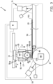
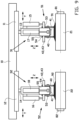
- Figure 5 shows the situation in which the trailing end TE1 of the first tire component 91 has reached a position at or near the end of the first conveyor 21, below the first pick-and-place unit 31.
- the steps of figures 2 and 3 are now repeated in figures 5 and 6 for the trailing ends TE1, TE2 of both tire components 91, 92.
- the positions of the pick-and-place units 31, 32 in the lateral direction Y can be controlled automatically and independently relative to each other, similar to the movements shown in figure 10 , to correct lateral misalignment between the trailing ends TE1, TE2 and the leading ends LE1, LE2.
Landscapes
- Engineering & Computer Science (AREA)
- Mechanical Engineering (AREA)
- Tyre Moulding (AREA)
Claims (19)
- Versorgungsvorrichtung (1) für zwei Reifenkomponenten zur Versorgung einer Reifenaufbautrommel mit einer ersten Reifenkomponente und einer zweiten Reifenkomponente, insbesondere Gürtelkantenpolster, wobei die Versorgungsvorrichtung für zwei Reifenkomponenten ein erstes Fördermittel (21) und ein zweites Fördermittel (22) zum Fördern jeweils der ersten Reifenkomponente und der zweiten Reifenkomponente in einer Versorgungsrichtung in Richtung der Reifenaufbautrommel aufweist, wobei die Versorgungsvorrichtung für zwei Reifenkomponenten ferner eine erste Bestückungseinheit (31) und eine zweite Bestückungseinheit (32) zur Übergabe jeweils der ersten Reifenkomponente und der zweiten Reifenkomponente von ihrem jeweiligen Fördermittel an die Reifenaufbautrommel aufweist, dadurch gekennzeichnet, dass die erste Bestückungseinheit (31) und die zweite Bestückungseinheit (32) automatisch und unabhängig relativ zueinander in einer Querrichtung senkrecht zu der Versorgungsrichtung beweglich sind.
- Versorgungsvorrichtung für zwei Reifenkomponenten nach Anspruch 1, wobei die Versorgungsvorrichtung für zwei Reifenkomponenten einen ersten Querantrieb und einen zweiten Querantrieb aufweist, die zum Antreiben der Bewegungen jeweils der ersten Bestückungseinheit und der zweiten Bestückungseinheit in der Querrichtung einzeln ansteuerbar sind.
- Versorgungsvorrichtung für zwei Reifenkomponenten nach Anspruch 1 oder 2, wobei die erste Bestückungseinheit und die zweite Bestückungseinheit in der Versorgungsrichtung synchron beweglich sind.
- Versorgungsvorrichtung für zwei Reifenkomponenten nach einem der vorhergehenden Ansprüche, wobei die Versorgungsvorrichtung für zwei Reifenkomponenten einen der ersten Bestückungseinheit und der zweiten Bestückungseinheit gemeinsamen Versorgungsantrieb aufweist, um die Bewegungen der ersten Bestückungseinheit und der zweiten Bestückungseinheit in der Versorgungsrichtung synchron anzutreiben.
- Versorgungsvorrichtung für zwei Reifenkomponenten nach einem der vorhergehenden Ansprüche, wobei die Versorgungsvorrichtung für zwei Reifenkomponenten ferner eine erste Sensoreinheit stromaufwärts der ersten Bestückungseinheit und der zweiten Bestückungseinheit relativ zu der Versorgungsrichtung zum Erfassen von Querpositionen der ersten Reifenkomponente und der zweiten Reifenkomponente jeweils auf dem ersten Fördermittel und dem zweiten Fördermittel aufweist,
wobei vorzugsweise die Versorgungsvorrichtung für zwei Reifenkomponenten einen ersten Querantrieb und einen zweiten Querantrieb aufweist, die zum Antreiben der Bewegungen jeweils der ersten Bestückungseinheit und der zweiten Bestückungseinheit in der Querrichtung einzeln ansteuerbar sind, und wobei die Versorgungsvorrichtung für zwei Reifenkomponenten mit einer Steuereinheit versehen ist, die zum Steuern der Bewegungen der ersten Bestückungseinheit und der zweiten Bestückungseinheit in der Querrichtung auf Grundlage von Erfassungssignalen von der ersten Sensoreinheit betrieblich mit dem ersten Querantrieb, dem zweiten Querantrieb und der ersten Sensoreinheit verbunden ist. - Versorgungsvorrichtung für zwei Reifenkomponenten nach einem der vorhergehenden Ansprüche, wobei die Versorgungsvorrichtung für zwei Reifenkomponenten ferner eine zweite Sensoreinheit stromabwärts der ersten Bestückungseinheit und der zweiten Bestückungseinheit relativ zu der Versorgungsrichtung zum Erfassen seitlicher Positionen der ersten Reifenkomponente und der zweiten Reifenkomponente auf der Reifenaufbautrommel aufweist,
wobei vorzugsweise die Versorgungsvorrichtung für zwei Reifenkomponenten einen ersten Querantrieb und einen zweiten Querantrieb aufweist, die zum Antreiben der Bewegungen der ersten Bestückungseinheit und der zweiten Bestückungseinheit in der Querrichtung einzeln ansteuerbar sind, und wobei die Versorgungsvorrichtung für zwei Reifenkomponenten mit einer Steuereinheit versehen ist, die zum Steuern der Bewegungen der ersten Bestückungseinheit und der zweiten Bestückungseinheit in der Querrichtung auf Grundlage von Erfassungssignalen von der zweiten Sensoreinheit betrieblich mit dem ersten Querantrieb, dem zweiten Querantrieb und der zweiten Sensoreinheit verbunden ist. - Versorgungsvorrichtung für zwei Reifenkomponenten nach einem der vorhergehenden Ansprüche, wobei die erste Reifenkomponente und die zweite Reifenkomponente jeweils ein vorderes Ende und ein hinteres Ende haben, wobei die erste Bestückungseinheit und die zweite Bestückungseinheit eingerichtet sind, zuerst das vordere Ende und anschließenden das hintere Ende jeweils der ersten Reifenkomponente und der zweiten Reifenkomponente zu übergeben, wobei die Versorgungsvorrichtung für zwei Reifenkomponenten mit einer Steuereinheit versehen ist, die zum Steuern der Bewegungen der ersten Bestückungseinheit und der zweiten Bestückungseinheit in der Querrichtung während zumindest der Übergabe des vorderen Endes und/oder der Übergabe des hinteren Endes derartig ausgelegt ist, dass Querpositionen jeder Reifenkomponente an dem vorderen Ende und dem hinteren Ende ausgerichtet sind.
- Versorgungsvorrichtung für zwei Reifenkomponenten nach einem der vorhergehenden Ansprüche, wobei jede Bestückungseinheit einen Greiferkopf und ein Halteelement zum Halten der jeweiligen Reifenkomponente an dem Greiferkopf aufweist,
wobei vorzugsweise das Halteelement ein Saugelement ist. - Versorgungsvorrichtung für zwei Reifenkomponenten nach Anspruch 8, wobei jede Bestückungseinheit ferner ein Löseelement zum Lösen der jeweiligen Reifenkomponente von dem Halteelement aufweist,wobei vorzugsweise das Löseelement eine Abstoßplatte aufweist, die relativ zu dem Halteelement in einer Bestückungsrichtung querverlaufend oder senkrecht zu der Versorgungsrichtung und der Querrichtung beweglich ist,wobei bevorzugter die Abstoßplatte zwischen einer eingefahrenen Position auf gleicher Höhe oder oberhalb des Halteelements in der Bestückungsrichtung und einer Abstoßposition unterhalb des Halteelements in der Bestückungsrichtung beweglich ist,wobei am meisten bevorzugt sich die Abstoßplatte zumindest teilweise um das Halteelement herum erstreckt, wenn die Abstoßplatte in der eingefahrenen Position ist.
- Versorgungsvorrichtung für zwei Reifenkomponenten nach einem der vorhergehenden Ansprüche, wobei die Versorgungsvorrichtung für zwei Reifenkomponenten ferner eine erste Presseinheit und eine zweite Presseinheit zum Pressen jeweils der ersten Reifenkomponente und der zweiten Reifenkomponente auf das jeweilige Fördermittel aufweist,wobei vorzugsweise die erste Presseinheit und die zweite Presseinheit jeweils von der ersten Bestückungseinheit und der zweiten Bestückungseinheit getragen werden,wobei bevorzugter die erste Presseinheit und die zweite Presseinheit in einer Bestückungsrichtung querverlaufend oder senkrecht zu der Versorgungsrichtung und der Querrichtung jeweils relativ zu der ersten Bestückungseinheit und der zweiten Bestückungseinheit beweglich sind.
- Versorgungsvorrichtung für zwei Reifenkomponenten nach Anspruch 10, wobei jede Presseinheit ein erstes Pressrad aufweist, das um eine Radachse parallel zu der Querrichtung drehbar ist,
wobei vorzugsweise das erste Pressrad ein profiliertes Rad mit Zähnen ist. - Versorgungsvorrichtung für zwei Reifenkomponenten nach Anspruch 11, wobei jede Presseinheit ein zu dem ersten Pressrad koaxiales und von ihm beabstandetes zweites Pressrad aufweist,
wobei vorzugsweise das zweite Pressrad ein profiliertes Rad mit Zähnen ist. - Versorgungsvorrichtung für zwei Reifenkomponenten nach einem der vorhergehenden Ansprüche, wobei die erste Reifenkomponente und die zweite Reifenkomponente jeweils ein vorderes Ende und ein hinteres Ende und eine Länge zwischen dem jeweiligen vorderen Ende und dem jeweiligen hinteren Ende hat, wobei die Versorgungsvorrichtung für zwei Reifenkomponenten ferner mindestens eine erste Sensoreinheit stromaufwärts von der ersten Bestückungseinheit und der zweiten Bestückungseinheit relativ zu der Versorgungsrichtung und/oder eine zweite Sensoreinheit stromabwärts von der ersten Bestückungseinheit relativ zu der Versorgungsrichtung aufweist, wobei die Versorgungsvorrichtung für zwei Reifenkomponenten mit einer Steuereinheit versehen ist, die zum Steuern eines Geschwindigkeitsverhältnisses zwischen dem jeweiligen Fördermittel und der Reifenaufbautrommel auf Grundlage von Erfassungssignalen von der ersten Sensoreinheit und/oder der zweiten Sensoreinheit ausgelegt ist, um die Länge für mindestens eine der Reifenkomponenten einzustellen.
- Verfahren zum Versorgen einer Reifenaufbautrommel mit einer ersten Reifenkomponente und einer zweiten Reifenkomponente, insbesondere Gürtelkantenpolster, unter Verwendung der Versorgungsvorrichtung für zwei Reifenkomponenten nach einem der vorhergehenden Ansprüche, wobei das Verfahren die Schritte aufweist:- Übergeben der ersten Reifenkomponente und der zweiten Reifenkomponente von ihrem jeweiligen Fördermittel an die Reifenaufbautrommel; und- während des Übergebens automatisches und unabhängiges Bewegen der ersten Bestückungseinheit und der zweiten Bestückungseinheit relativ zueinander in der Querrichtung.
- Verfahren nach Anspruch 14, wobei die erste Bestückungseinheit und die zweite Bestückungseinheit in Versorgungsrichtung synchron bewegt werden.
- Verfahren nach Anspruch 14 oder 15, wobei die erste Reifenkomponente und die zweite Reifenkomponente jeweils ein vorderes Ende und ein hinteres Ende haben, wobei die erste Bestückungseinheit und die zweite Bestückungseinheit zuerst das vordere Ende und anschließenden das hintere Ende der ersten Reifenkomponente und der zweiten Reifenkomponente übergeben, wobei die erste Bestückungseinheit und die zweite Bestückungseinheit während zumindest der Übergabe des vorderen Endes und/oder der Übergabe des hinteren Endes derartig in der Querrichtung bewegt werden, dass Querpositionen jeder Reifenkomponente an dem vorderen Ende und dem hinteren Ende ausgerichtet sind.
- Verfahren nach einem der Ansprüche 14-16, wobei die erste Reifenkomponente und die zweite Reifenkomponente jeweils an der ersten Bestückungseinheit und der zweiten Bestückungseinheit gehalten werden, wobei das Verfahren ferner den Schritt des Lösens der ersten Reifenkomponente und der zweiten Reifenkomponente jeweils von der ersten Bestückungseinheit und der zweiten Bestückungseinheit durch Abstoßen der ersten Reifenkomponente und der zweiten Reifenkomponente jeweils von der ersten Bestückungseinheit und der zweiten Bestückungseinheit aufweist.
- Verfahren nach einem der Ansprüche 14-17, wobei das Verfahren ferner den Schritt des Pressens der ersten Reifenkomponente und der zweiten Reifenkomponente auf das jeweilige Fördermittel aufweist.
- Verfahren nach einem der Ansprüche 14-18, wobei die erste Reifenkomponente und die zweite Reifenkomponente jeweils ein vorderes Ende und ein hinteres Ende und eine Länge zwischen dem jeweiligen vorderen Ende und dem jeweiligen hinteren Ende haben, wobei das Verfahren ferner den Schritt des Einstellens eines Geschwindigkeitsverhältnisses zwischen dem jeweiligen Fördermittel und der Reifenaufbautrommel aufweist, um die Länge für mindestens eine der Reifenkomponenten einzustellen.
Priority Applications (1)
| Application Number | Priority Date | Filing Date | Title |
|---|---|---|---|
| RS20250843A RS67134B1 (sr) | 2021-07-23 | 2022-06-29 | Serviser za dvostruku komponentu pneumatika i postupak za dopremanje dvostruke komponente pneumatika do bubnja za izradu pneumatika |
Applications Claiming Priority (3)
| Application Number | Priority Date | Filing Date | Title |
|---|---|---|---|
| NL2028821A NL2028821B1 (en) | 2021-07-23 | 2021-07-23 | Dual tire component servicer and method for supplying dual tire components to a tire building drum |
| NL2031427 | 2022-03-29 | ||
| PCT/NL2022/050368 WO2023003456A1 (en) | 2021-07-23 | 2022-06-29 | Dual tire component servicer and method for supplying dual tire components to a tire building drum |
Publications (3)
| Publication Number | Publication Date |
|---|---|
| EP4373659A1 EP4373659A1 (de) | 2024-05-29 |
| EP4373659C0 EP4373659C0 (de) | 2025-06-25 |
| EP4373659B1 true EP4373659B1 (de) | 2025-06-25 |
Family
ID=82321293
Family Applications (1)
| Application Number | Title | Priority Date | Filing Date |
|---|---|---|---|
| EP22735639.1A Active EP4373659B1 (de) | 2021-07-23 | 2022-06-29 | Versorgungsvorrichtung für zwei reifenkomponenten und verfahren zur versorgung einer reifenaufbautrommel mit zwei reifenkomponenten |
Country Status (10)
| Country | Link |
|---|---|
| US (1) | US12311625B2 (de) |
| EP (1) | EP4373659B1 (de) |
| JP (1) | JP7480339B2 (de) |
| KR (1) | KR102733395B1 (de) |
| CN (2) | CN218197083U (de) |
| BR (1) | BR112024001187A2 (de) |
| HU (1) | HUE072956T2 (de) |
| PL (1) | PL4373659T3 (de) |
| RS (1) | RS67134B1 (de) |
| WO (1) | WO2023003456A1 (de) |
Families Citing this family (1)
| Publication number | Priority date | Publication date | Assignee | Title |
|---|---|---|---|---|
| EP4373659B1 (de) * | 2021-07-23 | 2025-06-25 | VMI Holland B.V. | Versorgungsvorrichtung für zwei reifenkomponenten und verfahren zur versorgung einer reifenaufbautrommel mit zwei reifenkomponenten |
Family Cites Families (19)
| Publication number | Priority date | Publication date | Assignee | Title |
|---|---|---|---|---|
| IT1134875B (it) * | 1980-12-23 | 1986-08-20 | Pirelli | Apparecchiatura per l'alimentazione di stratia di rinforzo nella fabbricazione di pneumatici |
| JPS60131230A (ja) * | 1983-12-21 | 1985-07-12 | Bridgestone Corp | タイヤ用シ−ト状ゴム部材の周回貼合せ方法と装置 |
| JPH0777766B2 (ja) | 1987-04-21 | 1995-08-23 | 株式会社ブリヂストン | タイヤ構成部材の巻付け方法および装置 |
| WO1999017920A1 (fr) | 1997-10-03 | 1999-04-15 | Bridgestone Corporation | Procede et appareil pour former une couche de renfort d'un pneu |
| US6488193B1 (en) * | 1998-02-18 | 2002-12-03 | The Goodyear Tire & Rubber Co. | Guide conveyor having a laterally adjustable deflector roller at the end |
| US8454777B2 (en) * | 2006-01-30 | 2013-06-04 | Toyo Tire & Rubber Co., Ltd. | Method and apparatus of adhering and building belt member |
| DE102006017882B4 (de) * | 2006-04-13 | 2010-08-05 | Texmag Gmbh Vertriebsgesellschaft | Vorrichtung und Verfahren zum Aufbau eines Reifens |
| DE102008021042B4 (de) * | 2008-04-26 | 2023-09-28 | Continental Reifen Deutschland Gmbh | Verfahren zum Aufwickeln eines Materialstreifens auf eine Reifenaufbautrommel mit einem Servicer |
| WO2012066415A1 (en) | 2010-11-18 | 2012-05-24 | Pirelli Tyre S.P.A. | Process and apparatus for manufacturing tyres for vehicle wheels |
| FR2999470B1 (fr) * | 2012-12-13 | 2015-01-09 | Michelin & Cie | Procede et dispositif de fabrication d'ebauche de pneumatique |
| JP2015205427A (ja) * | 2014-04-18 | 2015-11-19 | 株式会社ブリヂストン | タイヤ構成部材の供給装置、タイヤ構成部材の供給方法、及び、未加硫タイヤの製造方法 |
| DE102014015490A1 (de) * | 2014-10-14 | 2016-04-14 | Harburg-Freudenberger Maschinenbau Gmbh | Vorrichtung und Verfahren zur Herstellung von Reifenrohlingen |
| CN111702822A (zh) | 2015-02-06 | 2020-09-25 | 斯第莱斯梯克有限公司 | 带形成系统 |
| NL2014365B1 (en) | 2015-02-27 | 2016-10-13 | Vmi Holland Bv | Conveyor and method for conveying a tire component. |
| DE102017222372A1 (de) * | 2017-12-11 | 2019-06-13 | Continental Reifen Deutschland Gmbh | Vorrichtung und Verfahren zum Aufwickeln eines zur Herstellung eines Gürtels eines Fahrzeugluftreifens geeigneten Gürtelaufbaustreifens auf eine Gürtelaufbautrommel |
| JP6881508B2 (ja) * | 2019-06-17 | 2021-06-02 | 横浜ゴム株式会社 | 未加硫の帯状ゴム部材の製造装置および方法 |
| JP6881507B2 (ja) * | 2019-06-17 | 2021-06-02 | 横浜ゴム株式会社 | 未加硫の環状ゴム部材の製造装置および方法 |
| CN219618553U (zh) * | 2021-07-23 | 2023-09-01 | Vmi荷兰公司 | 用于向轮胎成型鼓供应轮胎部件的轮胎部件供料器 |
| EP4373659B1 (de) * | 2021-07-23 | 2025-06-25 | VMI Holland B.V. | Versorgungsvorrichtung für zwei reifenkomponenten und verfahren zur versorgung einer reifenaufbautrommel mit zwei reifenkomponenten |
-
2022
- 2022-06-29 EP EP22735639.1A patent/EP4373659B1/de active Active
- 2022-06-29 JP JP2022562525A patent/JP7480339B2/ja active Active
- 2022-06-29 US US18/571,160 patent/US12311625B2/en active Active
- 2022-06-29 PL PL22735639.1T patent/PL4373659T3/pl unknown
- 2022-06-29 RS RS20250843A patent/RS67134B1/sr unknown
- 2022-06-29 BR BR112024001187A patent/BR112024001187A2/pt unknown
- 2022-06-29 WO PCT/NL2022/050368 patent/WO2023003456A1/en not_active Ceased
- 2022-06-29 KR KR1020247005915A patent/KR102733395B1/ko active Active
- 2022-06-29 HU HUE22735639A patent/HUE072956T2/hu unknown
- 2022-07-22 CN CN202221918511.8U patent/CN218197083U/zh active Active
- 2022-07-22 CN CN202210871410.8A patent/CN115674749B/zh active Active
Also Published As
| Publication number | Publication date |
|---|---|
| KR102733395B1 (ko) | 2024-11-21 |
| JP2023538166A (ja) | 2023-09-07 |
| CN115674749B (zh) | 2025-03-25 |
| EP4373659A1 (de) | 2024-05-29 |
| EP4373659C0 (de) | 2025-06-25 |
| JP7480339B2 (ja) | 2024-05-09 |
| HUE072956T2 (hu) | 2025-12-28 |
| KR20240036075A (ko) | 2024-03-19 |
| CN115674749A (zh) | 2023-02-03 |
| PL4373659T3 (pl) | 2025-11-03 |
| CN218197083U (zh) | 2023-01-03 |
| BR112024001187A2 (pt) | 2024-04-30 |
| US20240308163A1 (en) | 2024-09-19 |
| WO2023003456A1 (en) | 2023-01-26 |
| US12311625B2 (en) | 2025-05-27 |
| RS67134B1 (sr) | 2025-09-30 |
Similar Documents
| Publication | Publication Date | Title |
|---|---|---|
| US6547906B1 (en) | Process for transporting a belt construction strip for constructing a belt for a pneumatic vehicle tire | |
| US11850814B2 (en) | Device and method for producing unvulcanized band-shaped rubber member | |
| US20120248651A1 (en) | Method and apparatus for controlling the winding of an elongated element onto a collection reel with the interposition of a service fabric | |
| US20090126874A1 (en) | Supply device for a tire-building drum | |
| KR102611260B1 (ko) | 타이어 구성요소를 이송하기 위한 이송 장치, 어플리케이터 및 방법 | |
| EP4373659B1 (de) | Versorgungsvorrichtung für zwei reifenkomponenten und verfahren zur versorgung einer reifenaufbautrommel mit zwei reifenkomponenten | |
| JP3179131B2 (ja) | 帯状部材の貼付け方法および装置 | |
| CN219618553U (zh) | 用于向轮胎成型鼓供应轮胎部件的轮胎部件供料器 | |
| EP3630476B1 (de) | Verfahren und anordnung zum aufbringen einer reifenkomponente auf eine trommel | |
| NL2028821B1 (en) | Dual tire component servicer and method for supplying dual tire components to a tire building drum | |
| US10987888B2 (en) | Apparatus for manufacturing tire component member | |
| US20040188003A1 (en) | Splicing unit for splicing strips of cords embedded in rubber material to each other | |
| KR20150135201A (ko) | 타이어 구성요소를 형성하기 위한 타이어 성형기 및 방법 | |
| US20250187218A1 (en) | Cutting device and method for cutting a tire component | |
| KR920009953B1 (ko) | 타이어용 코드지의 재단방법과 그 장치 |
Legal Events
| Date | Code | Title | Description |
|---|---|---|---|
| STAA | Information on the status of an ep patent application or granted ep patent |
Free format text: STATUS: UNKNOWN |
|
| STAA | Information on the status of an ep patent application or granted ep patent |
Free format text: STATUS: THE INTERNATIONAL PUBLICATION HAS BEEN MADE |
|
| PUAI | Public reference made under article 153(3) epc to a published international application that has entered the european phase |
Free format text: ORIGINAL CODE: 0009012 |
|
| STAA | Information on the status of an ep patent application or granted ep patent |
Free format text: STATUS: REQUEST FOR EXAMINATION WAS MADE |
|
| 17P | Request for examination filed |
Effective date: 20231211 |
|
| AK | Designated contracting states |
Kind code of ref document: A1 Designated state(s): AL AT BE BG CH CY CZ DE DK EE ES FI FR GB GR HR HU IE IS IT LI LT LU LV MC MK MT NL NO PL PT RO RS SE SI SK SM TR |
|
| DAX | Request for extension of the european patent (deleted) | ||
| RAV | Requested validation state of the european patent: fee paid |
Extension state: MA Effective date: 20231211 |
|
| GRAP | Despatch of communication of intention to grant a patent |
Free format text: ORIGINAL CODE: EPIDOSNIGR1 |
|
| STAA | Information on the status of an ep patent application or granted ep patent |
Free format text: STATUS: GRANT OF PATENT IS INTENDED |
|
| INTG | Intention to grant announced |
Effective date: 20250128 |
|
| GRAS | Grant fee paid |
Free format text: ORIGINAL CODE: EPIDOSNIGR3 |
|
| GRAA | (expected) grant |
Free format text: ORIGINAL CODE: 0009210 |
|
| STAA | Information on the status of an ep patent application or granted ep patent |
Free format text: STATUS: THE PATENT HAS BEEN GRANTED |
|
| AK | Designated contracting states |
Kind code of ref document: B1 Designated state(s): AL AT BE BG CH CY CZ DE DK EE ES FI FR GB GR HR HU IE IS IT LI LT LU LV MC MK MT NL NO PL PT RO RS SE SI SK SM TR |
|
| REG | Reference to a national code |
Ref country code: GB Ref legal event code: FG4D |
|
| REG | Reference to a national code |
Ref country code: CH Ref legal event code: EP |
|
| REG | Reference to a national code |
Ref country code: DE Ref legal event code: R096 Ref document number: 602022016504 Country of ref document: DE |
|
| REG | Reference to a national code |
Ref country code: CH Ref legal event code: EP |
|
| REG | Reference to a national code |
Ref country code: IE Ref legal event code: FG4D |
|
| PGFP | Annual fee paid to national office [announced via postgrant information from national office to epo] |
Ref country code: AT Payment date: 20250721 Year of fee payment: 4 |
|
| U01 | Request for unitary effect filed |
Effective date: 20250717 |
|
| U07 | Unitary effect registered |
Designated state(s): AT BE BG DE DK EE FI FR IT LT LU LV MT NL PT RO SE SI Effective date: 20250725 |
|
| U20 | Renewal fee for the european patent with unitary effect paid |
Year of fee payment: 4 Effective date: 20250724 |
|
| PG25 | Lapsed in a contracting state [announced via postgrant information from national office to epo] |
Ref country code: NO Free format text: LAPSE BECAUSE OF FAILURE TO SUBMIT A TRANSLATION OF THE DESCRIPTION OR TO PAY THE FEE WITHIN THE PRESCRIBED TIME-LIMIT Effective date: 20250925 Ref country code: GR Free format text: LAPSE BECAUSE OF FAILURE TO SUBMIT A TRANSLATION OF THE DESCRIPTION OR TO PAY THE FEE WITHIN THE PRESCRIBED TIME-LIMIT Effective date: 20250926 |
|
| PG25 | Lapsed in a contracting state [announced via postgrant information from national office to epo] |
Ref country code: HR Free format text: LAPSE BECAUSE OF FAILURE TO SUBMIT A TRANSLATION OF THE DESCRIPTION OR TO PAY THE FEE WITHIN THE PRESCRIBED TIME-LIMIT Effective date: 20250625 |
|
| PGFP | Annual fee paid to national office [announced via postgrant information from national office to epo] |
Ref country code: RS Payment date: 20250709 Year of fee payment: 4 |
|
| PGFP | Annual fee paid to national office [announced via postgrant information from national office to epo] |
Ref country code: SK Payment date: 20250722 Year of fee payment: 4 |
|
| REG | Reference to a national code |
Ref country code: SK Ref legal event code: T3 Ref document number: E 47044 Country of ref document: SK |
|
| PGFP | Annual fee paid to national office [announced via postgrant information from national office to epo] |
Ref country code: HU Payment date: 20250722 Year of fee payment: 4 |
|
| REG | Reference to a national code |
Ref country code: HU Ref legal event code: AG4A Ref document number: E072956 Country of ref document: HU |
|
| PG25 | Lapsed in a contracting state [announced via postgrant information from national office to epo] |
Ref country code: IS Free format text: LAPSE BECAUSE OF FAILURE TO SUBMIT A TRANSLATION OF THE DESCRIPTION OR TO PAY THE FEE WITHIN THE PRESCRIBED TIME-LIMIT Effective date: 20251025 |
|
| PG25 | Lapsed in a contracting state [announced via postgrant information from national office to epo] |
Ref country code: SM Free format text: LAPSE BECAUSE OF FAILURE TO SUBMIT A TRANSLATION OF THE DESCRIPTION OR TO PAY THE FEE WITHIN THE PRESCRIBED TIME-LIMIT Effective date: 20250625 |
|
| PG25 | Lapsed in a contracting state [announced via postgrant information from national office to epo] |
Ref country code: CZ Free format text: LAPSE BECAUSE OF FAILURE TO SUBMIT A TRANSLATION OF THE DESCRIPTION OR TO PAY THE FEE WITHIN THE PRESCRIBED TIME-LIMIT Effective date: 20250625 |
|
| PGFP | Annual fee paid to national office [announced via postgrant information from national office to epo] |
Ref country code: PL Payment date: 20250708 Year of fee payment: 4 |
|
| REG | Reference to a national code |
Ref country code: CH Ref legal event code: H13 Free format text: ST27 STATUS EVENT CODE: U-0-0-H10-H13 (AS PROVIDED BY THE NATIONAL OFFICE) Effective date: 20260127 |
|
| PG25 | Lapsed in a contracting state [announced via postgrant information from national office to epo] |
Ref country code: ES Free format text: LAPSE BECAUSE OF FAILURE TO SUBMIT A TRANSLATION OF THE DESCRIPTION OR TO PAY THE FEE WITHIN THE PRESCRIBED TIME-LIMIT Effective date: 20250625 |
|
| VS25 | Lapsed in a validation state [announced via postgrant information from nat. office to epo] |
Ref country code: MA Free format text: FAILURE TO ELECT DOMICILE IN THE NATIONAL COUNTRY Effective date: 20250926 |