EP4279220B1 - Elektrowerkzeug mit spritzwasserschutz - Google Patents
Elektrowerkzeug mit spritzwasserschutz Download PDFInfo
- Publication number
- EP4279220B1 EP4279220B1 EP23171463.5A EP23171463A EP4279220B1 EP 4279220 B1 EP4279220 B1 EP 4279220B1 EP 23171463 A EP23171463 A EP 23171463A EP 4279220 B1 EP4279220 B1 EP 4279220B1
- Authority
- EP
- European Patent Office
- Prior art keywords
- opening
- electric tool
- splash guard
- battery block
- tool according
- Prior art date
- Legal status (The legal status is an assumption and is not a legal conclusion. Google has not performed a legal analysis and makes no representation as to the accuracy of the status listed.)
- Active
Links
Images


Classifications
-
- B—PERFORMING OPERATIONS; TRANSPORTING
- B25—HAND TOOLS; PORTABLE POWER-DRIVEN TOOLS; MANIPULATORS
- B25F—COMBINATION OR MULTI-PURPOSE TOOLS NOT OTHERWISE PROVIDED FOR; DETAILS OR COMPONENTS OF PORTABLE POWER-DRIVEN TOOLS NOT PARTICULARLY RELATED TO THE OPERATIONS PERFORMED AND NOT OTHERWISE PROVIDED FOR
- B25F5/00—Details or components of portable power-driven tools not particularly related to the operations performed and not otherwise provided for
- B25F5/02—Construction of casings, bodies or handles
-
- B—PERFORMING OPERATIONS; TRANSPORTING
- B25—HAND TOOLS; PORTABLE POWER-DRIVEN TOOLS; MANIPULATORS
- B25H—WORKSHOP EQUIPMENT, e.g. FOR MARKING-OUT WORK; STORAGE MEANS FOR WORKSHOPS
- B25H3/00—Storage means or arrangements for workshops facilitating access to, or handling of, work tools or instruments
Definitions
- the present invention relates, as stated in the preamble of claim 1, to a hand-held, mains-independent power tool, comprising a tool body comprising an electrical assembly, a handle connected to the latter and comprising an operating element, and a battery block, wherein at the lower end of the handle there is a connection base which is wider than the cross-section of the handle and is designed for exchangeable docking of the battery block, and wherein the battery block is at least partially surrounded by a separate splash guard.
- the present invention relates to such a hand-held, mains-independent power tool in the form of a hand-held hydraulic fluid device with an electrical assembly designed as an electrically operated pump, by means of which liquid can be fed to a nozzle (namely a jet or spray nozzle) which is typically arranged at the front of the tool body.
- a power tool according to the preamble of claim 1 is already known from JP 2009 262296 A known.
- Hand-held, mains-independent power tools of the generic type are enjoying great popularity, and are becoming increasingly popular due to increasingly powerful batteries, and are widely used. Cordless screwdrivers, cordless drills, cordless grinders, etc. are particularly popular.
- a rather new category of hand-held, mains-independent power tools with are hand-held hydraulic fluid devices, such as those used in the EP 2 663 405 B1 , EP 2 771 127 B1 , EP 2 994 240 B1 and US 9 192 952 B2
- the (post-published) DE 10 2021 103 306 A1 the applicant a hand-held hydraulic fluid device mains-independent power tool in the sense relevant here.
- the latter type of power tools which are designed as pressure fluid devices, are potentially exposed to the risk of getting wet (from splashing water or other liquid splashes) when used as intended.
- other types of power tools are also at risk, namely from rainwater, as they can potentially (also) be used in outdoor applications.
- protective covers - such as those offered by the manufacturer 3M - which are placed over the battery block from below and serve to mechanically protect the battery against impacts and to attach a safety line to prevent the tool from falling and are themselves fixed to the tool by means of a strap can also protect the battery block from splashing water.
- the EP 3 902 056 A2 discloses a protective cover for a battery - particularly for use on electrical devices for the home and garden - that serves as splash protection, with a cover that surrounds the battery.
- This consists of a rubber-elastic material such as natural rubber, silicone rubber or elastic thermoplastic, which allows the protective cover to be adapted to the respective battery, and in particular comprises a base and a surrounding wall, which has a flexible sealing lip on its upper edge. This is intended to cling to the housing of the electrical device equipped with the battery and in this way ensure that the battery is protected against the ingress of splash water.
- the sealing lip is clamped between the battery and a collar on the housing of the electrical device.
- the hand-held, mains-independent power tool is housed in a protective cover from which only the respective tool attachment (e.g. drill) protrudes.
- the present invention is aimed at reducing the risk of damage to hand-held, mains-independent power tools of the generic type, in particular to their battery block, by liquid, whereby one of the objectives is to reduce the risk of damage to the battery block as best as possible with comparatively little effort and the least possible negative effects on the handling of the hand-held power tool of the generic type in question.
- one of the objectives is to reduce the risk of damage to the battery block as best as possible with comparatively little effort and the least possible negative effects on the handling of the hand-held power tool of the generic type in question.
- the splash guard in a hand-held, mains-independent power tool of the generic type, is designed as a casing made of a highly elastic, waterproof flat material, which comprises a base section, a cover section opposite this, and side sections connecting the cover section and the base section, wherein the cover section has a first opening through which the handle passes above the connection base, and the base section is provided with a second opening that is larger than the first opening.
- the second opening is dimensioned in such a way that the splash guard can be pushed up or folded up and/or turned inside out over the battery block while widening the second opening, so that the battery block is at least partially exposed by emerging from the splash guard at the bottom.
- mains-independent power tool in particular for its practical use and good usability, is therefore the specific design of the separate splash guard, i.e. independent or separable from the rest of the power tool, so that the power tool is fully functional even without the splash guard.
- a particularly outstanding property of the splash guard is that it is manufactured from a highly elastic flat material and the presence of a comparatively large second opening in the base section means that it can remain on the rest of the power tool even when the battery block is being changed. To do this, it is sufficient that the splash guard is pushed or folded up over the battery block, widening the second opening, so that the battery block is at least partially exposed by emerging from the splash guard at the bottom.
- the battery block can then be removed from the connection base and replaced with a new one.
- the splash guard is pushed or folded down over the new battery block, with the base section - narrowing the second opening - forming a ring around the periphery of the base of the battery block. Because the splash guard remains on the power tool when the battery is changed, as intended, there is no risk of it being lost. This applies not only to the battery change phase, but in general.
- the first opening provided on the cover section of the splash guard which is smaller than the second opening, is of such a dimension that it can be widened to such an extent - by exploiting the elasticity of the material of the splash guard - that it can be pushed over the connection base when the battery block is removed and then - while narrowing - encloses the handle of the power tool, but that the connection base together with the docked battery block cannot, at least not repeatedly, pass through the correspondingly greatly widened first opening without there being a risk of lasting damage to the splash guard.
- a flat material is considered "highly elastic" in the sense of the present invention if it can be stretched to at least twice, preferably at least three times or, particularly preferably, even four times its area without damage and immediately and 100% returns to its original, unstretched shape when the stretching force ends.
- a highly elastic flat material that is waterproof in the sense of the present invention and which can be used particularly preferably in the context of the present invention is neoprene.
- information concerning the geometry or geometric characteristics of the splash guard refers, unless the context indicates otherwise, to the state removed from the power tool, i.e. the state not stretched or expanded by components of the power tool.
- the second opening which is ideally elliptical in terms of handling of the splash guard and its service life, accounts for between 50% and 90%, preferably between 60% and 80% of the area of the bottom section of the (unstretched) splash guard.
- the second opening is of such size that changing the battery (see above) is possible without effort; and also in view of the fact that liquid which under unfavourable circumstances could run down the handle of the power tool through the first opening of the splash guard and get into the interior of the power tool, should not remain "trapped" in the splash guard but rather be able to flow downwards as unhindered as possible, the said relationship between the dimension of the second opening and the area of the base section as a whole (including the area of the second opening) is very beneficial.
- the flat material is laminated on the inside with a woven, knitted or knitted fabric.
- a particularly advantageous property of such a lamination is that it functions as a water-conducting layer, should liquid enter the interior of the splash guard from above, i.e. through the upper, first opening, in the manner described above. Any liquid that has penetrated is guided downwards in the woven, knitted or knitted lamination, following gravity, in the direction of the base section and the second opening there.
- penetration into possible gaps, joints or the like in the housing of the battery block is counteracted. In this way, a This significantly defused a situation that was particularly critical for moisture penetration.
- Yet another preferred development of the present invention is characterized in that the flat material is coated with a sliding material on its inside, possibly on the inside of a lamination in the above sense.
- the sliding of the flat material of the splash guard on the battery block facilitated in this way can once again contribute to making battery replacement considerably easier.
- the side sections of the splash guard merge seamlessly into its cover section or its base section.
- the splash guard is assembled from two cut pieces, in particular - since the second embodiment is particularly preferred - from a first cut piece that forms the later cover section and from a second cut piece that forms the later base section and the later side sections.
- a particular advantage of this last embodiment is that there is no seam in the zone that is subject to particularly high mechanical stress at the transition from the base section to the four side sections.
- the side sections are preferably joined together in a watertight manner, in particular by being glued together in a watertight manner.
- seams if the side sections are sewn together, are particularly preferably designed in such a way that the sewing threads do not emerge on the inside of the flat material; the flat material is therefore not pierced. This also applies in a corresponding manner to seams which serve to connect the side sections to the cover section.
- At least one of the side sections has an opening closed with a transparent film material, forming a viewing window. This allows a display, possibly provided on the battery block, relating to the charge level of the battery block to be read without having to partially push up, fold over or roll up the splash guard.
- the hydraulic fluid device used in the embodiment of the invention illustrated in the drawing corresponds, unless otherwise stated in the present disclosure, in terms of its technical, functional and structural features to that device as described in the German patent application 10 2021 103 306.3 can be found in the applicant's application. Reference is made to this disclosure.
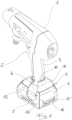
- the hydraulic fluid device has a tool body 1, which in turn comprises an electrical assembly with an electrically operated pump, wherein a handle 3 equipped with an operating element 2 is connected to the tool body 1, at the lower end of which a connection base 4 is provided which is wider than the cross-section of the handle 3 and which serves for the exchangeable docking of a battery block 5 and is prepared for this purpose.
- the connection base 4 and the battery block 5 are surrounded by a splash guard 6.
- the splash guard 6 is designed as a cover which consists of a highly elastic, waterproof flat material, namely neoprene coated on the inside with a sliding material.
- the cover comprises a base section 7, a cover section 8 opposite it and four side sections 9 connecting the cover section 8 and the base section 7.
- the cover section 8 has in the stress-free state, it has a first opening 10 which is approximately circular in shape and through which the handle 3 of the hydraulic fluid device passes above the connection base 4.
- the first opening 10 is adapted to the handle 3 in such a way that the cover section 8 above the connection base 4, in the area of the transition from the latter to the handle 3, lies tightly against the latter.
- the base section 7 is provided with a second opening 11 which is elliptical in the stress-free state. This is larger than the first opening 10.
- the splash guard 6 is assembled from two cut pieces, namely a first cut piece comprising the cover section 8 and a second cut piece comprising the base section 7 and the four side sections 9.
- the four side sections 9 are placed opposite the base section 7, which has an approximately rectangular basic shape, and are connected to one another at the edges using a combined sewing/glue joint 12 to form a surrounding wall.
- the cover section 8 is then connected to the four side sections 9 along their upper edges, also using a combined sewing/glue joint 13.
- the second opening 11 accounts for approximately 70% of the area of the base section 7 (including the second opening), so that - in other words - approximately 30% of the area of the base section 7 (including the second opening) remains as the edge section 14 surrounding the second opening 11. Due to the elliptical geometry of the second opening 11, the edge section 14 in the four corner areas of the base section 7 is particularly extended, but rather narrow between the corners. In other words: the material of the base section 7 of the splash guard 6 surrounding the second opening 11 is essentially concentrated on the four corner areas.
- the side section 9 which covers the rear front of the battery block 5 facing the user when the splash guard 6 is mounted has an opening 16 forming a viewing window 15 which is closed with a transparent film material 17. It is possible to read a charge level indicator 18 provided on the battery block 5 at any time through the viewing window 15, even when the splash guard 6 is in place.
- the battery change is not affected at all by the splash protection 6. This is because it can - by widening the second opening 11 - simply be pushed upwards over the battery block 5 placed on the connection base 4 until the battery block 5 is exposed and can be removed from the connection base 4 ( Fig. 3 ) and can be replaced by another battery block 5, whereupon the splash guard 6 is then pushed downwards again until the edge section 14 of the base section 7 surrounds the battery block 5 at the bottom edge ( Fig. 2 ).
Landscapes
- Engineering & Computer Science (AREA)
- Mechanical Engineering (AREA)
- Battery Mounting, Suspending (AREA)
Description
- Die vorliegende Erfindung betrifft, wie im Oberbegriff des Anspruchs 1 angegeben, ein handgeführtes, netzunabhängiges Elektrowerkzeug, umfassend einen eine elektrische Baugruppe umfassenden Werkzeugkörper, einen mit diesem verbundenen, ein Bedienelement umfassenden Handgriff und einen Batterieblock, wobei am unteren Ende des Handgriffs ein gegenüber dem Querschnitt des Handgriffs erweiterter, für ein auswechselbares Andocken des Batterieblocks hergerichteter Anschlusssockel vorgesehen und wobei weiterhin der Batterieblock zumindest teilweise von einem gesonderten Spritzwasserschutz umgeben ist. Insbesondere betrifft die vorliegende Erfindung dabei ein solches handgeführtes, netzunabhängiges Elektrowerkzeug in Form eines handgeführten Druckflüssigkeitsgeräts mit einer als elektrisch betriebene Pumpe ausgeführten elektrischen Baugruppe, mittels derer Flüssigkeit einer typischerweise vorne an dem Werkzeugkörper angeordneten Düse (namentlich einer Strahl- oder Sprühdüse) zuführbar ist. Ein Elektrowerkzeug gemäß dem Oberbegriff des Anspruchs 1 ist bereits aus der
JP 2009 262296 A - Handgeführte, netzunabhängige Elektrowerkzeuge der gattungsgemäßen Art erfreuen sich großer, angesichts immer leistungsfähigerer Batterien weiter zunehmender Beliebtheit und sind weit verbreitet. Besonders verbreitet sind Akkuschrauber, Akkubohrer, Akkuschleifer, etc. Eine eher neue Kategorie gattungsgemäßer handgeführter, netzunabhängiger Elektrowerkzeuge mit sind handgeführte Druckflüssigkeitsgeräte, wie sie beispielsweise der
EP 2 663 405 B1 ,EP 2 771 127 B1 ,EP 2 994 240 B1 undUS 9 192 952 B2 DE 10 2021 103 306 A1 der Anmelderin ein als handgeführtes Druckflüssigkeitsgerät ausgeführtes netzunabhängiges Elektrowerkzeug im hier maßgeblichen Sinne. - Namentlich die zuletzt genannten, als Drückflüssigkeitsgerät ausgeführten gattungsgemäßen Elektrowerkzeuge sind potentiell der Gefahr ausgesetzt, bei ihrer bestimmungsgemäßen Verwendung (durch Spritzwasser bzw. sonstige Flüssigkeitsspritzer) nass zu werden. Aber auch andere gattungsgemäße Elektrowerkzeuge sind, da sie potentiell (auch) in Outdoor-Anwendungen zum Einsatz kommen können, entsprechend gefährdet, namentlich durch Regenwasser.
- Das Schadpotential ist besonders erheblich, wenn entsprechende Flüssigkeit (Säuren, Laugen, Reinigungsflüssigkeit, Lösungsmittel, Wasser, etc.) in den Batterieblock eindringt. Vor diesem Hintergrund bestehen bereits Ansätze, den Batterieblock durch einen ihn zumindest teilweise umgebenden, gesonderten (d. h. von dem Batterieblock unabhängigen bzw. trennbaren) Spritzwasserschutz in Form einer Umhüllung zu schützen. In diesem Zusammenhang ist namentlich zu verweisen auf die
US 8 733 471 B2 . In gewissem Umfang können, gewissermaßen als Nebeneffekt, auch solche - beispielsweise von dem Hersteller 3M angebotene - von unten über den Batterieblock gestülpte Schutzhüllen, die dem mechanischen Schutz der Batterie vor Stößen und der Anbringung eines das Herabfallen des Werkzeugs verhindernden Sicherungsleine dienen und selber mittels eines Riemens an dem Werkzeug fixiert werden, den Batterieblock vor Spritzwasser schützen. - Die
EP 3 902 056 A2 offenbart eine dem Spritzwasserschutz dienende Schutzhülle für einen - insbesondere an Elektrogeräten für Haus und Garten einsetzbaren - Akkumulator mit einem den Akkumulator umschließenden Überzug. Dieser besteht aus einem gummielastischen Material wie Naturkautschuk, Silikonkautschuk oder elastischem Thermoplast, was eine Anpassung der Schutzhülle an den jeweiligen Akkumulator erlaubt, und umfasst insbesondere einen Boden und eine umlaufende Wand, welche an ihrem oberen Rand eine flexible Dichtlippe aufweist. Diese soll sich an das Gehäuse des mit dem Akkumulator ausgestatteten Elektrogeräts anschmiegen und auf diese Weise gewährleisten, dass der Akkumulator vor dem Eindringen von Spritzwasser geschützt ist. In einer Ausgestaltung wird die Dichtlippe hierzu zwischen dem Akkumulator und einem an dem Gehäuse des Elektrogeräts ausgeführten Bund eingeklemmt. - Nach der
WO 2014/001 747 A2 wird als Alternative zu einem gesonderten Spritzwasserschutz (nur) für den Batterieblock das handgeführte, netzunabhängige Elektrowerkzeug insgesamt in einer Schutzhülle aufgenommen, aus dem lediglich der jeweilige Werkzeugaufsatz (z. B. Bohrer) herausragt. - Vor diesem Hintergrund ist die vorliegende Erfindung darauf gerichtet, das Risiko einer Beschädigung von handgeführten, netzunabhängigen Elektrowerkzeugen der gattungsgemäßen Art, insbesondere von deren Batterieblock durch Flüssigkeit zu reduzieren, wobei es namentlich eine Zielsetzung ist, mit vergleichsweise geringem Aufwand und geringstmöglichen negativen Auswirkungen auf die Handhabbarkeit des betreffenden gattungsgemäßen handgeführten Elektrowerkzeugs bestmöglich die Gefahr einer Beschädigung des Batterieblocks durch Flüssigkeitsspritzer, insbesondere Spritzwasser, zu minimieren.
- Die Lösung dieser Aufgabenstellung erfolgt, wie in Anspruch 1 angegeben, erfindungsgemäß dadurch, dass bei einem handgeführten, netzunabhängigen Elektrowerkzeug der gattungsgemäßen Art der Spritzwasserschutz als eine aus einem hochelastischen wasserundurchlässigen Flachmaterial bestehende Hülle ausgeführt ist, welche einen Bodenabschnitt, einen diesem gegenüberliegenden Deckelabschnitt und den Deckelabschnitt und den Bodenabschnitt miteinander verbindende Seitenabschnitte umfasst, wobei der Deckelabschnitt einen ersten Durchbruch, durch welchen der Handgriff oberhalb des Anschlusssockels hindurchtritt, aufweist und der Bodenabschnitt mit einem gegenüber dem ersten Durchbruch größeren zweiten Durchbruch versehen ist. Der zweite Durchbruch ist dabei dergestalt dimensioniert, dass der Spritzwasserschutz unter Aufweitung des zweiten Durchbruchs über den Batterieblock hochgeschoben bzw. hochgeschlagen und/oder umgekrempelt werden kann, so dass der Batterieblock zumindest teilweise freiliegt, indem er unten aus dem Spritzwasserschutz heraustritt. Von Bedeutung für das erfindungsgemäße handgeführte, netzunabhängige Elektrowerkzeug, namentlich für dessen praktischen Nutzen und gute Verwendbarkeit ist demnach die spezifische Ausführung des gesonderten, d. h. in dem Sinne von dem übrigen Elektrowerkzeug unabhängigen bzw. trennbaren Spritzwasserschutz, dass das Elektrowerkzeug auch ohne den Spritzwasserschutz uneingeschränkt funktionstauglich ist. Eine besonders herausragende Eigenschaft des Spritzwasserschutzes ist dabei, dass dieser infolge seiner Herstellung aus einem hochelastischen Flachmaterial und der Anwesenheit eines vergleichsweise groß dimensionierten zweiten Durchbruchs im Bodenabschnitt auch dann an dem übrigen Elektrowerkzeug verbleiben kann, wenn der Batterieblock gewechselt wird. Hierzu reicht nämlich aus, dass der Spritzwasserschutz unter Aufweitung des zweiten Durchbruchs über den Batterieblock hochgeschoben bzw. hochgeschlagen und/oder umgekrempelt wird, so dass der Batterieblock zumindest teilweise freiliegt, indem er unten aus dem Spritzwasserschutz heraustritt. So kann der Batterieblock von dem Anschlusssockel abgenommen und durch einen neuen ersetzt werden. Nach dem Batteriewechsel wird der Spritzwasserschutz über den neuen Batterieblock heruntergeschoben bzw. -gekrempelt, wobei sich der Bodenabschnitt - unter Verengung des zweiten Durchbruchs - ringförmig an die Peripherie des Bodens des Batterieblocks anlegt. Der Spritzwasserschutz ist, weil er bestimmungsgemäß bei dem Batteriewechsel an dem Elektrowerkzeug verbleibt, nicht der Gefahr ausgesetzt verloren zu gehen. Dies gilt im Übrigen nicht nur für die Phase des Batteriewechsels, sondern generell. Denn der an dem Deckelabschnitt des Spritzwasserschutzes vorgesehene, gegenüber dem zweiten Durchbruch kleinere erste Durchbruch ist von einer solchen Dimension, dass er - unter Ausnutzung der Elastizität des Werkstoffs des Spritzwasserschutzes - zwar so weit aufgeweitet werden kann, dass er bei abgenommenem Batterieblock über den Anschlusssockel geschoben werden kann und hernach - unter Verengung - den Handgriff des Elektrowerkzeugs umschließt, dass indessen der Anschlusssockel mitsamt dem angedocktem Batterieblock nicht, zumindest nicht wiederholt, durch den entsprechend stark aufgeweiteten ersten Durchbruch hindurchtreten kann, ohne dass die Gefahr einer nachhaltigen Beschädigung des Spritzschutzes besteht.
- Als "hochelastisch" im Sinne der vorliegenden Erfindung ist ein Flachmaterial dann anzusehen, wenn es schadlos auf mindestens das Doppelte, bevorzugt auf mindestens das Dreifache oder, besonders bevorzugt sogar auf mindestens das Vierfache seiner Fläche gedehnt werden kann und aus seiner Dehnung sofort und zu 100% in seine ursprüngliche, ungedehnte Form zurückkehrt, wenn die Dehnkraft endet. Ein in diesem Sinne der vorliegenden Erfindung wasserundurchlässiges hochelastisches Flachmaterial, welches im Rahmen der vorliegenden Erfindung besonders bevorzugt zum Einsatz kommen kann, ist Neopren.
- Zur Vermeidung von Missverständnissen bzw. Fehlinterpretationen ist darauf hinzuweisen, dass die Geometrie bzw. geometrische Merkmale des Spritzwasserschutzes betreffende Angaben (z. B. das Größenverhältnis zwischen den beiden Durchbrüchen) sich, sofern sich nicht aus dem Sinnzusammenhang etwas Anderes ergibt, auf den von dem Elektrowerkzeug abgenommenen, d. h. den nicht durch Komponenten des Elektrowerkzeugs gedehnten bzw. geweiteten Zustand beziehen.
- Gemäß einer besonders bevorzugten Ausgestaltung der Erfindung macht der zweite Durchbruch, welcher im Hinblick auf die Handhabung des Spritzwasserschutzes sowie dessen Lebensdauer idealerweise elliptisch ausgeführt ist, einen Anteil von zwischen 50% und 90%, bevorzugt zwischen 60% und 80% der Fläche des Bodenabschnitts des (nicht gedehnten) Spritzschutzes aus. Auf diese Weise ergibt sich eine besonders vorteilhafte Kombination von Eigenschaften. Hierzu zählt, dass der an dem Boden des Batterieblocks anliegende, den zweiten Durchbruch umgebende Ringbereich des Spritzschutzes, d. h. dessen Bodenabschnitt, ausreichend groß dimensioniert ist, um für einen effektiven mechanischen Schutz des Batterieblocks zu sorgen. Auf der anderen Seite ist der zweite Durchbruch von solcher Ausdehnung, dass der Batteriewechsel (s. o.) ohne Mühe möglich ist; und auch im Hinblick darauf, dass Flüssigkeit, welche unter ungünstigen Umständen an dem Handgriff des Elektrowerkzeugs herabrinnend durch den ersten Durchbruch des Spritzschutzes hindurch in dessen Inneres gelangen könnte, nicht in dem Spritzschutz "gefangen" bleiben sondern vielmehr möglichst ungehindert nach unten abfließen können sollte, ist die besagte Relation zwischen der Dimension des zweiten Durchbruchs und der Fläche des Bodenabschnitts insgesamt (einschließlich der Fläche des zweiten Durchbruchs) sehr förderlich.
- Gemäß einer wiederum anderen bevorzugten Weiterbildung der Erfindung ist das Flachmaterial auf der Innenseite mit einem Gewebe, Gewirk oder Gestrick kaschiert. Eine besonders günstige Eigenschaft einer solchen Kaschierung ist, dass sie gewissermaßen als wasserführende Schicht fungiert, sollte auf die oben dargelegte Weise Flüssigkeit von oben, d. h. durch den oberen, ersten Durchbruch hindurch in das Innere des Spritzschutzes gelangen. Entsprechende eingedrungene Flüssigkeit wird, der Schwerkraft folgend, in der Gewebe-, Gewirk- oder Gestrick-Kaschierung nach unten in Richtung auf den Bodenabschnitt und den dort bestehenden zweiten Durchbruch geleitet. Indem sie in der aus Gewebe-, Gewirk- oder Gestrick bestehenden Schicht geführt und gehalten wird, wird einem Eindringen in mögliche Spalte, Fugen oder dergleichen in dem Gehäuse des Batterieblocks entgegengewirkt. Auf diese Weise wird eine für eindringende Feuchtigkeit besonders kritische Situation entscheidend entschärft.
- Eine nochmals andere bevorzugte Weiterbildung der vorliegenden Erfindung zeichnet sich dadurch aus, dass das Flachmaterial auf seiner Innenseite, ggf. auf der Innenseite einer Kaschierung im vorstehenden Sinne, mit einem Gleitmaterial beschichtet ist. Das auf diese Weise begünstigte Gleiten des Flachmaterials des Spritzwasserschutzes auf dem Batterieblock erleichtert kann nochmals zu einer erheblichen Erleichterung des Batteriewechsels beitragen.
- Gemäß einer wiederum anderen bevorzugten Weiterbildung der Erfindung gehen die Seitenabschnitte des Spritzschutzes nahtlos in dessen Deckelabschnitt oder aber dessen Bodenabschnitt über. Bei dieser Weiterbildung wird der Spritzschutz jeweils aus zwei Zuschnitten gefügt, insbesondere - nachdem dabei die an zweiter Stelle genannte Ausführung ganz besonders bevorzugt wird - aus einem den späteren Deckelabschnitt bildenden ersten Zuschnitt und aus einem den späteren Bodenabschnitt und die späteren Seitenabschnitte bildenden zweiten Zuschnitt. Ein besonderer Vorteil dieser zuletzt genannten Ausführung besteht darin, dass in der mechanisch besonders beanspruchten Zone am Übergang von dem Bodenabschnitt zu den vier Seitenabschnitten keine Naht vorliegt.
- Die Seitenabschnitte sind dabei bevorzugt untereinander wasserdicht gefügt, insbesondere indem sie wasserdicht miteinander verklebt sind. Entsprechendes gilt für die Verbindung der Seitenabschnitte mit dem Deckelabschnitt. Im Hinblick auf einen besonders effektiven Schutz des Batterieblocks vor Spitzwasser sind Nähte, sofern die Seitenabschnitte miteinander vernäht sind, besonders bevorzugt so ausgeführt, dass die Nähfäden nicht auf der Innenseite des Flachmaterials heraustreten; das Flachmaterial wird demgemäß nicht durchstochen. Auch dies gilt wiederum in entsprechender Weise für Nähte, welche der Verbindung der Seitenabschnitte mit dem Deckelabschnitt dienen.
- In nochmals anderer bevorzugter Ausgestaltung der Erfindung weist mindestens einer der Seitenabschnitte einen mit einem durchsichtigen Folienmaterial verschlossenen, ein Sichtfenster bildenden Durchbruch auf. Dies erlaubt es, eine ggf. an dem Batterieblock vorgesehene Anzeige betreffend den Ladezustand des Batterieblocks abzulesen, ohne hierzu den Spritzschutz teilweise hochschieben, umschlagen oder hochkrempeln zu müssen.
- Im Folgenden wird die vorliegende Erfindung anhand eines in der Zeichnung veranschaulichten bevorzugten Ausführungsbeispiels näher erläutert. Dabei zeigt
- Fig. 1
- in perspektivischer Ansicht schräg von hintenlinks-oben ein als erfindungsgemäßes Druckflüssigkeitsgerät ausgeführtes handgeführtes, netzunabhängiges Elektrowerkzeug,
- Fig. 2
- das Druckflüssigkeitsgerät nach
Fig. 1 in Seitenansicht von rechts, wobei der Spritzwasserschutz in der Mittelebene geschnitten dargestellt ist, und - Fig. 3
- das Druckflüssigkeitsgerät nach
Fig. 2 beim Batteriewechsel. - Das im Rahmen des in der Zeichnung veranschaulichten Ausführungsbeispiels der Erfindung zum Einsatz kommende Druckflüssigkeitsgerät entspricht, soweit sich aus der vorliegenden Offenbarung nichts Anderes ergibt, hinsichtlich seiner technischen, funktionellen und strukturellen Merkmale jenem Gerät, wie es der
deutschen Patentanmeldung 10 2021 103 306.3 der Anmelderin entnehmbar ist. Auf diese Offenbarung wird verwiesen und Bezug genommen. Vorstehendes gilt, zusätzlich zu diversen Ausgestaltungsmerkmalen, insbesondere hinsichtlich des grundlegenden strukturellen bzw. funktionellen Aufbaus dahingehend, dass das Druckflüssigkeitsgerät einen Werkzeugkörper 1 aufweist, der seinerseits eine elektrische Baugruppe mit einer elektrisch betriebenen Pumpe umfasst, wobei mit dem Werkzeugkörper 1 ein mit einem Bedienelement 2 ausgestatteter Handgriff 3 verbundenen ist, an dessen unterem Ende ein gegenüber dem Querschnitt des Handgriffs 3 erweiterter Anschlusssockel 4 vorgesehen ist, welcher dem auswechselbaren Andocken eines Batterieblocks 5 dient und hierfür hergerichtet ist. - Der Anschlusssockel 4 und der Batterieblock 5 sind von einem Spritzwasserschutz 6 umgeben. Dieser bildet ein gesondertes Ausstattungsteil in dem Sinne, dass das Druckflüssigkeitsgerät auch ohne ihn funktionsfähig und einsetzbar ist. Der Spritzwasserschutz 6 ist als eine Hülle ausgeführt, welche aus einem hochelastischen wasserundurchlässigen Flachmaterial, nämlich aus innenseitig mit einem Gleitmaterial beschichteten Neopren besteht. Die Hülle umfasst einen Bodenabschnitt 7, einen diesem gegenüberliegenden Deckelabschnitt 8 und vier den Deckelabschnitt 8 und den Bodenabschnitt 7 miteinander verbindende Seitenabschnitte 9. Der Deckelabschnitt 8 weist dabei einen im spannungsfreien Zustand etwa kreisförmigen ersten Durchbruch 10 auf, durch welchen der Handgriff 3 des Druckflüssigkeitsgeräts oberhalb des Anschlusssockels 4 hindurchtritt. Hinsichtlich seiner Dimension ist der erste Durchbruch 10 dabei so auf den Handgriff 3 abgestimmt, dass der Deckelabschnitt 8 oberhalb des Anschlusssockels 4, im Bereich des Übergangs von diesem zum Handgriff 3, eng an letzterem anliegt. Der Bodenabschnitt 7 ist mit einem im spannungsfreien Zustand elliptischen zweiten Durchbruch 11 versehen. Dieser ist größer als der erste Durchbruch 10.
- Der Spritzwasserschutz 6 ist aus zwei Zuschnitten zusammengefügt, nämlich einem den Deckelabschnitt 8 umfassenden ersten Zuschnitt und einem den Bodenabschnitt 7 und die vier Seitenabschnitte 9 umfassenden zweiten Zuschnitt. Zur Fertigung werden die vier Seitenabschnitte 9 gegenüber dem - eine etwa rechteckige Grundform aufweisenden - Bodenabschnitt 7 aufgestellt und - zur Bildung einer umlaufenden Wandung - randseitig jeweils mittels einer kombinierten Näh/Klebe-Fügung 12 untereinander verbunden. Anschließend wird - ebenfalls mittels einer kombinierten Näh/Klebe-Fügung 13 - der Deckelabschnitt 8 längs deren oberen Rändern mit den vier Seitenabschnitten 9 verbunden.
- Der zweite Durchbruch 11 macht einen Anteil von etwa 70% der Fläche des Bodenabschnitts 7 (den zweiten Durchbruch eingerechnet) aus, so dass - mit anderen Worten - etwa 30% der Fläche des Bodenabschnitts 7 (den zweiten Durchbruch eingerechnet) als den zweiten Durchbruch 11 umgebender Randabschnitt 14 verbleiben. Infolge der elliptischen Geometrie des zweiten Durchbruchs 11 ist der Randabschnitt 14 in den vier Eckbereichen des Bodenabschnitts 7 besonders ausgedehnt, jeweils zwischen den Ecken demgegenüber eher schmal. Mit anderen Worten: Das den zweiten Durchbruch 11 umgebende Material des Bodenabschnitts 7 des Spritzwasserschutzes 6 konzentriert sich im Wesentlichen auf die vier Eckbereiche.
- Jener Seitenabschnitt 9, welcher im montierten Zustand des Spritzwasserschutzes 6 die dem Benutzer zugewandte rückwärtige Front des Batterieblocks 5 abdeckt, weist einen ein Sichtfenster 15 bildenden Durchbruch 16 auf, welcher mit einem durchsichtigen Folienmaterial 17 verschlossen ist. Durch das Sichtfenster 15 hindurch ist das auch bei aufgesetztem Spritzwasserschutz 6 jederzeit das Ablesen einer an dem Batterieblock 5 vorgesehenen Ladezustandsanzeige 18 möglich.
- Wie sich aus dem Vergleich der
Figuren 2 und3 erkennen lässt, ist der Batteriewechsel durch den Spritzwasserschutz 6 überhaupt nicht beeinträchtigt. Denn dieser lässt sich - unter Aufweitung des zweiten Durchbruchs 11 - einfach über den auf den Anschlusssockel 4 aufgesetzten Batterieblock 5 hinweg so weit nach oben schieben, bis der Batterieblock 5 freiliegt, von dem Anschlusssockel 4 abgenommen (Fig. 3 ) und durch einen anderen Batterieblock 5 ersetzt werden kann, woraufhin der Spritzwasserschutz 6 anschließend wieder so weit nach unten geschoben wird, dass der Randabschnitt 14 des Bodenabschnitts 7 den Batterieblock 5 unten randseitig umgreift (Fig. 2 ).
Claims (9)
- Handgeführtes, netzunabhängiges Elektrowerkzeug, insbesondere handgeführtes Druckflüssigkeitsgerät, umfassend einen eine elektrische Baugruppe, insbesondere eine elektrisch betriebene Pumpe umfassenden Werkzeugkörper (1), einen mit diesem verbundenen, ein Bedienelement (2) umfassenden Handgriff (3) und einen Batterieblock (5), wobei am unteren Ende des Handgriffs (3) ein gegenüber dem Querschnitt des Handgriffs (3) erweiterter, für ein auswechselbares Andocken des Batterieblocks (5) hergerichteter Anschlusssockel (4) vorgesehen und wobei weiterhin der Batterieblock (5) zumindest teilweise von einem gesonderten Spritzwasserschutz (6) umgeben ist,
wobei der Spritzwasserschutz (6) als eine aus einem hochelastischen wasserundurchlässigen Flachmaterial bestehende Hülle ausgeführt ist, welche einen Bodenabschnitt (7), einen diesem gegenüberliegenden Deckelabschnitt (8) und den Deckelabschnitt (8)und den Bodenabschnitt (7) miteinander verbindende Seitenabschnitte (9) umfasst, wobei der Deckelabschnitt (8) einen ersten Durchbruch (10), durch welchen der Handgriff (3) oberhalb des Anschlusssockels (4) hindurchtritt, aufweist gekennzeichnet dadurch, dass der Bodenabschnitt (7) mit einem gegenüber dem ersten Durchbruch (10) größeren, dergestalt dimensionierten zweiten Durchbruch (11) versehen ist, dass der Spritzwasserschutz (6) unter Aufweitung des zweiten Durchbruchs (11) über den Batterieblock (5) hochgeschoben bzw. hochgeschlagen und/oder umgekrempelt werden kann, so dass der Batterieblock (5) zumindest teilweise freiliegt, indem er unten aus dem Spritzwasserschutz (6) heraustritt. - Elektrowerkzeug nach Anspruch 1, dadurch gekennzeichnet, dass der zweite Durchbruch (11) einen Anteil von zwischen 50% und 90%, bevorzugt zwischen 60% und 80% der Fläche des Bodenabschnitts (7) ausmacht.
- Elektrowerkzeug nach Anspruch 1 oder Anspruch 2, dadurch gekennzeichnet, dass das Flachmaterial auf der Innenseite mit einem Gewebe, Gewirk oder Gestrick kaschiert ist.
- Elektrowerkzeug nach einem der Ansprüche 1 bis 3, dadurch gekennzeichnet, dass das Flachmaterial auf seiner Innenseite, ggf. auf der Innenseite einer Kaschierung im Sinne des Anspruchs 3, mit einem Gleitmaterial beschichtet ist.
- Elektrowerkzeug nach einem der Ansprüche 1 bis 4, dadurch gekennzeichnet, dass die Seitenabschnitte (9) nahtlos in den Deckelabschnitt (8) oder den Bodenabschnitt (7) übergehen.
- Elektrowerkzeug nach einem der Ansprüche 1 bis 5, dadurch gekennzeichnet, dass die Seitenabschnitte (9) untereinander wasserdicht gefügt, insbesondere wasserdicht miteinander verklebt sind.
- Elektrowerkzeug nach einem der Ansprüche 1 bis 6, dadurch gekennzeichnet, dass die Seitenabschnitte (9) miteinander vernäht sind, wobei die Nähfäden nicht auf der Innenseite des Flachmaterials heraustreten.
- Elektrowerkzeug nach einem der Ansprüche 1 bis 7, dadurch gekennzeichnet, dass mindestens einer der Seitenabschnitte (9) einen mit einem durchsichtigen Folienmaterial (17) verschlossenen, ein Sichtfenster (15) bildenden Durchbruch (16) aufweist.
- Elektrowerkzeug nach einem der Ansprüche 1 bis 8, dadurch gekennzeichnet, dass der zweite Durchbruch (11) elliptisch ausgeführt ist.
Applications Claiming Priority (1)
| Application Number | Priority Date | Filing Date | Title |
|---|---|---|---|
| DE102022112466.5A DE102022112466B3 (de) | 2022-05-18 | 2022-05-18 | Elektrowerkzeug |
Publications (2)
| Publication Number | Publication Date |
|---|---|
| EP4279220A1 EP4279220A1 (de) | 2023-11-22 |
| EP4279220B1 true EP4279220B1 (de) | 2024-11-13 |
Family
ID=86329855
Family Applications (1)
| Application Number | Title | Priority Date | Filing Date |
|---|---|---|---|
| EP23171463.5A Active EP4279220B1 (de) | 2022-05-18 | 2023-05-04 | Elektrowerkzeug mit spritzwasserschutz |
Country Status (2)
| Country | Link |
|---|---|
| EP (1) | EP4279220B1 (de) |
| DE (1) | DE102022112466B3 (de) |
Family Cites Families (10)
| Publication number | Priority date | Publication date | Assignee | Title |
|---|---|---|---|---|
| JP4705970B2 (ja) * | 2008-04-28 | 2011-06-22 | 勝也 酒井 | 電動工具用の工具カバ及び換気補助器 |
| JP5587801B2 (ja) | 2010-09-13 | 2014-09-10 | 株式会社マキタ | 充電式電動工具 |
| TWI559981B (en) | 2011-01-14 | 2016-12-01 | Graco Minnesota Inc | Fluid dispensing device |
| EP2663407A4 (de) | 2011-01-14 | 2017-02-22 | Graco Minnesota Inc. | Steuerventil zur druckeinstellung einer luftlosen sprühvorrichtung |
| CN107262308B (zh) | 2011-10-27 | 2022-07-08 | 固瑞克明尼苏达有限公司 | 具有可收缩衬管的喷涂器流体供应系统 |
| GB201211466D0 (en) | 2012-06-28 | 2012-08-08 | Secr Defence | Waterproof casing for a powertool |
| EP2994240B1 (de) | 2013-05-08 | 2019-02-13 | Graco Minnesota Inc. | Farbdosenadapter für tragbare sprühvorrichtung |
| US9833893B2 (en) * | 2013-09-27 | 2017-12-05 | Ty-Flot, Inc. | Drop-prevention pouch for cordless power tools |
| DE202020102191U1 (de) | 2020-04-21 | 2021-07-22 | Markus Kress | Schutzhülle für eine Speichereinrichtung und Verwendung derselben |
| DE102021103306A1 (de) | 2021-02-12 | 2022-08-18 | Kolektor Group D.O.O. | Handgeführtes Druckflüssigkeitsgerät |
-
2022
- 2022-05-18 DE DE102022112466.5A patent/DE102022112466B3/de active Active
-
2023
- 2023-05-04 EP EP23171463.5A patent/EP4279220B1/de active Active
Also Published As
| Publication number | Publication date |
|---|---|
| EP4279220A1 (de) | 2023-11-22 |
| DE102022112466B3 (de) | 2023-07-20 |
Similar Documents
| Publication | Publication Date | Title |
|---|---|---|
| EP2459042B1 (de) | Staubsauger mit abnehmbarem deckel | |
| EP2281497B1 (de) | Filtervorrichtung für einen Staubsauger | |
| DE202017001077U1 (de) | Staubsauger | |
| DE3883610T2 (de) | Vorrichtung und Verfahren zum Handhaben von schädlichen Stoffen. | |
| DE102022112466B3 (de) | Elektrowerkzeug | |
| EP0444291A1 (de) | Textiltragetasche aus thermoplastischem Kunststoff und Verfahren zu ihrer Herstellung | |
| DE102012104102A1 (de) | Feuchtreinigungsvorrichtung | |
| DE202004011734U1 (de) | Sicherheits-Bekleidungsstück | |
| DE20022430U1 (de) | Schutzvorrichtung für die Montage und Entsorgung von Werkbankfiltern | |
| DE10147778A1 (de) | Putzhandschuh-Vorrichtung | |
| DE202008011302U1 (de) | Batteriegehäuse mit Befestigungsfunktion | |
| DE10222005B4 (de) | Schutzeinrichtung für das Endstück der Zapfwelle eines Traktors | |
| DE3130856A1 (de) | Abdeckung fuer ein fahrzeug | |
| AT523811B1 (de) | Arbeitsgerät und Arbeitsgerät-Hülle | |
| DE4439364C2 (de) | Textilbespannung für Bodenreinigungsgeräte | |
| DE8805982U1 (de) | Vorrichtung zum Ausfiltern von Feinststaub aus der Abluft von Staubsaugern | |
| DE102023120532A1 (de) | Hochdruckreinigungsgerät | |
| EP0075778B1 (de) | Wasserdichtes Isolierstoffgehäuse | |
| DE4332092C2 (de) | Elektrische Zahnbürste | |
| DE102006025999A1 (de) | Schutztasche für aufklappbare Mobilfunktelefone | |
| EP0903085A2 (de) | Zum einmaligen Gebrauch bestimmte Schürze, insbesondere für medizinische Zwecke | |
| EP4576956A1 (de) | Gehäuse für elektronische komponenten | |
| DE102011055445A1 (de) | Reinigungsvorrichtung mit einem Saugkanal | |
| DE20115937U1 (de) | Putzhandschuh-Vorrichtung | |
| DE202022100834U1 (de) | Desinfektionsvorrichtung für Mund-Nasen-Bedeckungen |
Legal Events
| Date | Code | Title | Description |
|---|---|---|---|
| PUAI | Public reference made under article 153(3) epc to a published international application that has entered the european phase |
Free format text: ORIGINAL CODE: 0009012 |
|
| STAA | Information on the status of an ep patent application or granted ep patent |
Free format text: STATUS: THE APPLICATION HAS BEEN PUBLISHED |
|
| AK | Designated contracting states |
Kind code of ref document: A1 Designated state(s): AL AT BE BG CH CY CZ DE DK EE ES FI FR GB GR HR HU IE IS IT LI LT LU LV MC ME MK MT NL NO PL PT RO RS SE SI SK SM TR |
|
| STAA | Information on the status of an ep patent application or granted ep patent |
Free format text: STATUS: REQUEST FOR EXAMINATION WAS MADE |
|
| 17P | Request for examination filed |
Effective date: 20240328 |
|
| RBV | Designated contracting states (corrected) |
Designated state(s): AL AT BE BG CH CY CZ DE DK EE ES FI FR GB GR HR HU IE IS IT LI LT LU LV MC ME MK MT NL NO PL PT RO RS SE SI SK SM TR |
|
| GRAP | Despatch of communication of intention to grant a patent |
Free format text: ORIGINAL CODE: EPIDOSNIGR1 |
|
| STAA | Information on the status of an ep patent application or granted ep patent |
Free format text: STATUS: GRANT OF PATENT IS INTENDED |
|
| INTG | Intention to grant announced |
Effective date: 20240606 |
|
| GRAS | Grant fee paid |
Free format text: ORIGINAL CODE: EPIDOSNIGR3 |
|
| GRAA | (expected) grant |
Free format text: ORIGINAL CODE: 0009210 |
|
| STAA | Information on the status of an ep patent application or granted ep patent |
Free format text: STATUS: THE PATENT HAS BEEN GRANTED |
|
| AK | Designated contracting states |
Kind code of ref document: B1 Designated state(s): AL AT BE BG CH CY CZ DE DK EE ES FI FR GB GR HR HU IE IS IT LI LT LU LV MC ME MK MT NL NO PL PT RO RS SE SI SK SM TR |
|
| P01 | Opt-out of the competence of the unified patent court (upc) registered |
Free format text: CASE NUMBER: APP_53333/2024 Effective date: 20241001 |
|
| REG | Reference to a national code |
Ref country code: GB Ref legal event code: FG4D Free format text: NOT ENGLISH |
|
| REG | Reference to a national code |
Ref country code: CH Ref legal event code: EP |
|
| REG | Reference to a national code |
Ref country code: IE Ref legal event code: FG4D Free format text: LANGUAGE OF EP DOCUMENT: GERMAN |
|
| REG | Reference to a national code |
Ref country code: DE Ref legal event code: R096 Ref document number: 502023000290 Country of ref document: DE |
|
| REG | Reference to a national code |
Ref country code: LT Ref legal event code: MG9D |
|
| REG | Reference to a national code |
Ref country code: NL Ref legal event code: MP Effective date: 20241113 |
|
| PG25 | Lapsed in a contracting state [announced via postgrant information from national office to epo] |
Ref country code: IS Free format text: LAPSE BECAUSE OF FAILURE TO SUBMIT A TRANSLATION OF THE DESCRIPTION OR TO PAY THE FEE WITHIN THE PRESCRIBED TIME-LIMIT Effective date: 20250313 Ref country code: PT Free format text: LAPSE BECAUSE OF FAILURE TO SUBMIT A TRANSLATION OF THE DESCRIPTION OR TO PAY THE FEE WITHIN THE PRESCRIBED TIME-LIMIT Effective date: 20250313 Ref country code: HR Free format text: LAPSE BECAUSE OF FAILURE TO SUBMIT A TRANSLATION OF THE DESCRIPTION OR TO PAY THE FEE WITHIN THE PRESCRIBED TIME-LIMIT Effective date: 20241113 |
|
| PG25 | Lapsed in a contracting state [announced via postgrant information from national office to epo] |
Ref country code: FI Free format text: LAPSE BECAUSE OF FAILURE TO SUBMIT A TRANSLATION OF THE DESCRIPTION OR TO PAY THE FEE WITHIN THE PRESCRIBED TIME-LIMIT Effective date: 20241113 Ref country code: NL Free format text: LAPSE BECAUSE OF FAILURE TO SUBMIT A TRANSLATION OF THE DESCRIPTION OR TO PAY THE FEE WITHIN THE PRESCRIBED TIME-LIMIT Effective date: 20241113 |
|
| PG25 | Lapsed in a contracting state [announced via postgrant information from national office to epo] |
Ref country code: BG Free format text: LAPSE BECAUSE OF FAILURE TO SUBMIT A TRANSLATION OF THE DESCRIPTION OR TO PAY THE FEE WITHIN THE PRESCRIBED TIME-LIMIT Effective date: 20241113 |
|
| PG25 | Lapsed in a contracting state [announced via postgrant information from national office to epo] |
Ref country code: ES Free format text: LAPSE BECAUSE OF FAILURE TO SUBMIT A TRANSLATION OF THE DESCRIPTION OR TO PAY THE FEE WITHIN THE PRESCRIBED TIME-LIMIT Effective date: 20241113 |
|
| PG25 | Lapsed in a contracting state [announced via postgrant information from national office to epo] |
Ref country code: NO Free format text: LAPSE BECAUSE OF FAILURE TO SUBMIT A TRANSLATION OF THE DESCRIPTION OR TO PAY THE FEE WITHIN THE PRESCRIBED TIME-LIMIT Effective date: 20250213 |
|
| PG25 | Lapsed in a contracting state [announced via postgrant information from national office to epo] |
Ref country code: LV Free format text: LAPSE BECAUSE OF FAILURE TO SUBMIT A TRANSLATION OF THE DESCRIPTION OR TO PAY THE FEE WITHIN THE PRESCRIBED TIME-LIMIT Effective date: 20241113 Ref country code: GR Free format text: LAPSE BECAUSE OF FAILURE TO SUBMIT A TRANSLATION OF THE DESCRIPTION OR TO PAY THE FEE WITHIN THE PRESCRIBED TIME-LIMIT Effective date: 20250214 |
|
| PG25 | Lapsed in a contracting state [announced via postgrant information from national office to epo] |
Ref country code: PL Free format text: LAPSE BECAUSE OF FAILURE TO SUBMIT A TRANSLATION OF THE DESCRIPTION OR TO PAY THE FEE WITHIN THE PRESCRIBED TIME-LIMIT Effective date: 20241113 |
|
| PG25 | Lapsed in a contracting state [announced via postgrant information from national office to epo] |
Ref country code: RS Free format text: LAPSE BECAUSE OF FAILURE TO SUBMIT A TRANSLATION OF THE DESCRIPTION OR TO PAY THE FEE WITHIN THE PRESCRIBED TIME-LIMIT Effective date: 20250213 |
|
| PG25 | Lapsed in a contracting state [announced via postgrant information from national office to epo] |
Ref country code: SM Free format text: LAPSE BECAUSE OF FAILURE TO SUBMIT A TRANSLATION OF THE DESCRIPTION OR TO PAY THE FEE WITHIN THE PRESCRIBED TIME-LIMIT Effective date: 20241113 |
|
| PG25 | Lapsed in a contracting state [announced via postgrant information from national office to epo] |
Ref country code: DK Free format text: LAPSE BECAUSE OF FAILURE TO SUBMIT A TRANSLATION OF THE DESCRIPTION OR TO PAY THE FEE WITHIN THE PRESCRIBED TIME-LIMIT Effective date: 20241113 |
|
| PG25 | Lapsed in a contracting state [announced via postgrant information from national office to epo] |
Ref country code: EE Free format text: LAPSE BECAUSE OF FAILURE TO SUBMIT A TRANSLATION OF THE DESCRIPTION OR TO PAY THE FEE WITHIN THE PRESCRIBED TIME-LIMIT Effective date: 20241113 |
|
| PG25 | Lapsed in a contracting state [announced via postgrant information from national office to epo] |
Ref country code: RO Free format text: LAPSE BECAUSE OF FAILURE TO SUBMIT A TRANSLATION OF THE DESCRIPTION OR TO PAY THE FEE WITHIN THE PRESCRIBED TIME-LIMIT Effective date: 20241113 |
|
| PGFP | Annual fee paid to national office [announced via postgrant information from national office to epo] |
Ref country code: AT Payment date: 20250721 Year of fee payment: 3 |
|
| PG25 | Lapsed in a contracting state [announced via postgrant information from national office to epo] |
Ref country code: SK Free format text: LAPSE BECAUSE OF FAILURE TO SUBMIT A TRANSLATION OF THE DESCRIPTION OR TO PAY THE FEE WITHIN THE PRESCRIBED TIME-LIMIT Effective date: 20241113 |
|
| PG25 | Lapsed in a contracting state [announced via postgrant information from national office to epo] |
Ref country code: CZ Free format text: LAPSE BECAUSE OF FAILURE TO SUBMIT A TRANSLATION OF THE DESCRIPTION OR TO PAY THE FEE WITHIN THE PRESCRIBED TIME-LIMIT Effective date: 20241113 |
|
| PG25 | Lapsed in a contracting state [announced via postgrant information from national office to epo] |
Ref country code: IT Free format text: LAPSE BECAUSE OF FAILURE TO SUBMIT A TRANSLATION OF THE DESCRIPTION OR TO PAY THE FEE WITHIN THE PRESCRIBED TIME-LIMIT Effective date: 20241113 |
|
| REG | Reference to a national code |
Ref country code: DE Ref legal event code: R097 Ref document number: 502023000290 Country of ref document: DE |
|
| PG25 | Lapsed in a contracting state [announced via postgrant information from national office to epo] |
Ref country code: SE Free format text: LAPSE BECAUSE OF FAILURE TO SUBMIT A TRANSLATION OF THE DESCRIPTION OR TO PAY THE FEE WITHIN THE PRESCRIBED TIME-LIMIT Effective date: 20241113 |
|
| PLBE | No opposition filed within time limit |
Free format text: ORIGINAL CODE: 0009261 |
|
| STAA | Information on the status of an ep patent application or granted ep patent |
Free format text: STATUS: NO OPPOSITION FILED WITHIN TIME LIMIT |
|
| PGFP | Annual fee paid to national office [announced via postgrant information from national office to epo] |
Ref country code: DE Payment date: 20250729 Year of fee payment: 3 |
|
| 26N | No opposition filed |
Effective date: 20250814 |
|
| PG25 | Lapsed in a contracting state [announced via postgrant information from national office to epo] |
Ref country code: LU Free format text: LAPSE BECAUSE OF NON-PAYMENT OF DUE FEES Effective date: 20250504 |
|
| REG | Reference to a national code |
Ref country code: BE Ref legal event code: MM Effective date: 20250531 |
|
| PG25 | Lapsed in a contracting state [announced via postgrant information from national office to epo] |
Ref country code: MC Free format text: LAPSE BECAUSE OF FAILURE TO SUBMIT A TRANSLATION OF THE DESCRIPTION OR TO PAY THE FEE WITHIN THE PRESCRIBED TIME-LIMIT Effective date: 20241113 |
|
| PG25 | Lapsed in a contracting state [announced via postgrant information from national office to epo] |
Ref country code: IE Free format text: LAPSE BECAUSE OF NON-PAYMENT OF DUE FEES Effective date: 20250504 |
|
| PG25 | Lapsed in a contracting state [announced via postgrant information from national office to epo] |
Ref country code: BE Free format text: LAPSE BECAUSE OF NON-PAYMENT OF DUE FEES Effective date: 20250531 |
|
| PG25 | Lapsed in a contracting state [announced via postgrant information from national office to epo] |
Ref country code: FR Free format text: LAPSE BECAUSE OF NON-PAYMENT OF DUE FEES Effective date: 20250531 |