EP4257397B1 - Fahrzeuggetriebeschaltsteuerungsvorrichtung und fahrzeug - Google Patents
Fahrzeuggetriebeschaltsteuerungsvorrichtung und fahrzeug Download PDFInfo
- Publication number
- EP4257397B1 EP4257397B1 EP23163737.2A EP23163737A EP4257397B1 EP 4257397 B1 EP4257397 B1 EP 4257397B1 EP 23163737 A EP23163737 A EP 23163737A EP 4257397 B1 EP4257397 B1 EP 4257397B1
- Authority
- EP
- European Patent Office
- Prior art keywords
- vehicle
- gear
- controller
- shift
- shifting
- Prior art date
- Legal status (The legal status is an assumption and is not a legal conclusion. Google has not performed a legal analysis and makes no representation as to the accuracy of the status listed.)
- Active
Links
Images


Classifications
-
- B—PERFORMING OPERATIONS; TRANSPORTING
- B60—VEHICLES IN GENERAL
- B60K—ARRANGEMENT OR MOUNTING OF PROPULSION UNITS OR OF TRANSMISSIONS IN VEHICLES; ARRANGEMENT OR MOUNTING OF PLURAL DIVERSE PRIME-MOVERS IN VEHICLES; AUXILIARY DRIVES FOR VEHICLES; INSTRUMENTATION OR DASHBOARDS FOR VEHICLES; ARRANGEMENTS IN CONNECTION WITH COOLING, AIR INTAKE, GAS EXHAUST OR FUEL SUPPLY OF PROPULSION UNITS IN VEHICLES
- B60K6/00—Arrangement or mounting of plural diverse prime-movers for mutual or common propulsion, e.g. hybrid propulsion systems comprising electric motors and internal combustion engines
- B60K6/20—Arrangement or mounting of plural diverse prime-movers for mutual or common propulsion, e.g. hybrid propulsion systems comprising electric motors and internal combustion engines the prime-movers consisting of electric motors and internal combustion engines, e.g. HEVs
- B60K6/50—Architecture of the driveline characterised by arrangement or kind of transmission units
- B60K6/54—Transmission for changing ratio
- B60K6/547—Transmission for changing ratio the transmission being a stepped gearing
-
- B—PERFORMING OPERATIONS; TRANSPORTING
- B60—VEHICLES IN GENERAL
- B60K—ARRANGEMENT OR MOUNTING OF PROPULSION UNITS OR OF TRANSMISSIONS IN VEHICLES; ARRANGEMENT OR MOUNTING OF PLURAL DIVERSE PRIME-MOVERS IN VEHICLES; AUXILIARY DRIVES FOR VEHICLES; INSTRUMENTATION OR DASHBOARDS FOR VEHICLES; ARRANGEMENTS IN CONNECTION WITH COOLING, AIR INTAKE, GAS EXHAUST OR FUEL SUPPLY OF PROPULSION UNITS IN VEHICLES
- B60K6/00—Arrangement or mounting of plural diverse prime-movers for mutual or common propulsion, e.g. hybrid propulsion systems comprising electric motors and internal combustion engines
- B60K6/20—Arrangement or mounting of plural diverse prime-movers for mutual or common propulsion, e.g. hybrid propulsion systems comprising electric motors and internal combustion engines the prime-movers consisting of electric motors and internal combustion engines, e.g. HEVs
- B60K6/22—Arrangement or mounting of plural diverse prime-movers for mutual or common propulsion, e.g. hybrid propulsion systems comprising electric motors and internal combustion engines the prime-movers consisting of electric motors and internal combustion engines, e.g. HEVs characterised by apparatus, components or means specially adapted for HEVs
- B60K6/38—Arrangement or mounting of plural diverse prime-movers for mutual or common propulsion, e.g. hybrid propulsion systems comprising electric motors and internal combustion engines the prime-movers consisting of electric motors and internal combustion engines, e.g. HEVs characterised by apparatus, components or means specially adapted for HEVs characterised by the driveline clutches
- B60K6/387—Actuated clutches, i.e. clutches engaged or disengaged by electric, hydraulic or mechanical actuating means
-
- B—PERFORMING OPERATIONS; TRANSPORTING
- B60—VEHICLES IN GENERAL
- B60K—ARRANGEMENT OR MOUNTING OF PROPULSION UNITS OR OF TRANSMISSIONS IN VEHICLES; ARRANGEMENT OR MOUNTING OF PLURAL DIVERSE PRIME-MOVERS IN VEHICLES; AUXILIARY DRIVES FOR VEHICLES; INSTRUMENTATION OR DASHBOARDS FOR VEHICLES; ARRANGEMENTS IN CONNECTION WITH COOLING, AIR INTAKE, GAS EXHAUST OR FUEL SUPPLY OF PROPULSION UNITS IN VEHICLES
- B60K6/00—Arrangement or mounting of plural diverse prime-movers for mutual or common propulsion, e.g. hybrid propulsion systems comprising electric motors and internal combustion engines
- B60K6/20—Arrangement or mounting of plural diverse prime-movers for mutual or common propulsion, e.g. hybrid propulsion systems comprising electric motors and internal combustion engines the prime-movers consisting of electric motors and internal combustion engines, e.g. HEVs
- B60K6/42—Arrangement or mounting of plural diverse prime-movers for mutual or common propulsion, e.g. hybrid propulsion systems comprising electric motors and internal combustion engines the prime-movers consisting of electric motors and internal combustion engines, e.g. HEVs characterised by the architecture of the hybrid electric vehicle
- B60K6/48—Parallel type
-
- B—PERFORMING OPERATIONS; TRANSPORTING
- B60—VEHICLES IN GENERAL
- B60W—CONJOINT CONTROL OF VEHICLE SUB-UNITS OF DIFFERENT TYPE OR DIFFERENT FUNCTION; CONTROL SYSTEMS SPECIALLY ADAPTED FOR HYBRID VEHICLES; ROAD VEHICLE DRIVE CONTROL SYSTEMS FOR PURPOSES NOT RELATED TO THE CONTROL OF A PARTICULAR SUB-UNIT
- B60W10/00—Conjoint control of vehicle sub-units of different type or different function
- B60W10/04—Conjoint control of vehicle sub-units of different type or different function including control of propulsion units
- B60W10/08—Conjoint control of vehicle sub-units of different type or different function including control of propulsion units including control of electric propulsion units, e.g. motors or generators
-
- B—PERFORMING OPERATIONS; TRANSPORTING
- B60—VEHICLES IN GENERAL
- B60W—CONJOINT CONTROL OF VEHICLE SUB-UNITS OF DIFFERENT TYPE OR DIFFERENT FUNCTION; CONTROL SYSTEMS SPECIALLY ADAPTED FOR HYBRID VEHICLES; ROAD VEHICLE DRIVE CONTROL SYSTEMS FOR PURPOSES NOT RELATED TO THE CONTROL OF A PARTICULAR SUB-UNIT
- B60W10/00—Conjoint control of vehicle sub-units of different type or different function
- B60W10/10—Conjoint control of vehicle sub-units of different type or different function including control of change-speed gearings
- B60W10/11—Stepped gearings
-
- B—PERFORMING OPERATIONS; TRANSPORTING
- B60—VEHICLES IN GENERAL
- B60W—CONJOINT CONTROL OF VEHICLE SUB-UNITS OF DIFFERENT TYPE OR DIFFERENT FUNCTION; CONTROL SYSTEMS SPECIALLY ADAPTED FOR HYBRID VEHICLES; ROAD VEHICLE DRIVE CONTROL SYSTEMS FOR PURPOSES NOT RELATED TO THE CONTROL OF A PARTICULAR SUB-UNIT
- B60W10/00—Conjoint control of vehicle sub-units of different type or different function
- B60W10/18—Conjoint control of vehicle sub-units of different type or different function including control of braking systems
- B60W10/184—Conjoint control of vehicle sub-units of different type or different function including control of braking systems with wheel brakes
- B60W10/188—Conjoint control of vehicle sub-units of different type or different function including control of braking systems with wheel brakes hydraulic brakes
-
- B—PERFORMING OPERATIONS; TRANSPORTING
- B60—VEHICLES IN GENERAL
- B60W—CONJOINT CONTROL OF VEHICLE SUB-UNITS OF DIFFERENT TYPE OR DIFFERENT FUNCTION; CONTROL SYSTEMS SPECIALLY ADAPTED FOR HYBRID VEHICLES; ROAD VEHICLE DRIVE CONTROL SYSTEMS FOR PURPOSES NOT RELATED TO THE CONTROL OF A PARTICULAR SUB-UNIT
- B60W20/00—Control systems specially adapted for hybrid vehicles
- B60W20/10—Controlling the power contribution of each of the prime movers to meet required power demand
- B60W20/15—Control strategies specially adapted for achieving a particular effect
- B60W20/16—Control strategies specially adapted for achieving a particular effect for reducing engine exhaust emissions
-
- B—PERFORMING OPERATIONS; TRANSPORTING
- B60—VEHICLES IN GENERAL
- B60W—CONJOINT CONTROL OF VEHICLE SUB-UNITS OF DIFFERENT TYPE OR DIFFERENT FUNCTION; CONTROL SYSTEMS SPECIALLY ADAPTED FOR HYBRID VEHICLES; ROAD VEHICLE DRIVE CONTROL SYSTEMS FOR PURPOSES NOT RELATED TO THE CONTROL OF A PARTICULAR SUB-UNIT
- B60W30/00—Purposes of road vehicle drive control systems not related to the control of a particular sub-unit, e.g. of systems using conjoint control of vehicle sub-units
- B60W30/02—Control of vehicle driving stability
-
- B—PERFORMING OPERATIONS; TRANSPORTING
- B60—VEHICLES IN GENERAL
- B60W—CONJOINT CONTROL OF VEHICLE SUB-UNITS OF DIFFERENT TYPE OR DIFFERENT FUNCTION; CONTROL SYSTEMS SPECIALLY ADAPTED FOR HYBRID VEHICLES; ROAD VEHICLE DRIVE CONTROL SYSTEMS FOR PURPOSES NOT RELATED TO THE CONTROL OF A PARTICULAR SUB-UNIT
- B60W30/00—Purposes of road vehicle drive control systems not related to the control of a particular sub-unit, e.g. of systems using conjoint control of vehicle sub-units
- B60W30/18—Propelling the vehicle
- B60W30/18009—Propelling the vehicle related to particular drive situations
- B60W30/18109—Braking
- B60W30/18127—Regenerative braking
-
- B—PERFORMING OPERATIONS; TRANSPORTING
- B60—VEHICLES IN GENERAL
- B60W—CONJOINT CONTROL OF VEHICLE SUB-UNITS OF DIFFERENT TYPE OR DIFFERENT FUNCTION; CONTROL SYSTEMS SPECIALLY ADAPTED FOR HYBRID VEHICLES; ROAD VEHICLE DRIVE CONTROL SYSTEMS FOR PURPOSES NOT RELATED TO THE CONTROL OF A PARTICULAR SUB-UNIT
- B60W30/00—Purposes of road vehicle drive control systems not related to the control of a particular sub-unit, e.g. of systems using conjoint control of vehicle sub-units
- B60W30/18—Propelling the vehicle
- B60W30/18009—Propelling the vehicle related to particular drive situations
- B60W30/18145—Cornering
-
- B—PERFORMING OPERATIONS; TRANSPORTING
- B60—VEHICLES IN GENERAL
- B60K—ARRANGEMENT OR MOUNTING OF PROPULSION UNITS OR OF TRANSMISSIONS IN VEHICLES; ARRANGEMENT OR MOUNTING OF PLURAL DIVERSE PRIME-MOVERS IN VEHICLES; AUXILIARY DRIVES FOR VEHICLES; INSTRUMENTATION OR DASHBOARDS FOR VEHICLES; ARRANGEMENTS IN CONNECTION WITH COOLING, AIR INTAKE, GAS EXHAUST OR FUEL SUPPLY OF PROPULSION UNITS IN VEHICLES
- B60K6/00—Arrangement or mounting of plural diverse prime-movers for mutual or common propulsion, e.g. hybrid propulsion systems comprising electric motors and internal combustion engines
- B60K6/20—Arrangement or mounting of plural diverse prime-movers for mutual or common propulsion, e.g. hybrid propulsion systems comprising electric motors and internal combustion engines the prime-movers consisting of electric motors and internal combustion engines, e.g. HEVs
- B60K6/42—Arrangement or mounting of plural diverse prime-movers for mutual or common propulsion, e.g. hybrid propulsion systems comprising electric motors and internal combustion engines the prime-movers consisting of electric motors and internal combustion engines, e.g. HEVs characterised by the architecture of the hybrid electric vehicle
- B60K6/48—Parallel type
- B60K2006/4825—Electric machine connected or connectable to gearbox input shaft
-
- B—PERFORMING OPERATIONS; TRANSPORTING
- B60—VEHICLES IN GENERAL
- B60W—CONJOINT CONTROL OF VEHICLE SUB-UNITS OF DIFFERENT TYPE OR DIFFERENT FUNCTION; CONTROL SYSTEMS SPECIALLY ADAPTED FOR HYBRID VEHICLES; ROAD VEHICLE DRIVE CONTROL SYSTEMS FOR PURPOSES NOT RELATED TO THE CONTROL OF A PARTICULAR SUB-UNIT
- B60W2520/00—Input parameters relating to overall vehicle dynamics
- B60W2520/14—Yaw
-
- B—PERFORMING OPERATIONS; TRANSPORTING
- B60—VEHICLES IN GENERAL
- B60W—CONJOINT CONTROL OF VEHICLE SUB-UNITS OF DIFFERENT TYPE OR DIFFERENT FUNCTION; CONTROL SYSTEMS SPECIALLY ADAPTED FOR HYBRID VEHICLES; ROAD VEHICLE DRIVE CONTROL SYSTEMS FOR PURPOSES NOT RELATED TO THE CONTROL OF A PARTICULAR SUB-UNIT
- B60W2520/00—Input parameters relating to overall vehicle dynamics
- B60W2520/26—Wheel slip
-
- B—PERFORMING OPERATIONS; TRANSPORTING
- B60—VEHICLES IN GENERAL
- B60W—CONJOINT CONTROL OF VEHICLE SUB-UNITS OF DIFFERENT TYPE OR DIFFERENT FUNCTION; CONTROL SYSTEMS SPECIALLY ADAPTED FOR HYBRID VEHICLES; ROAD VEHICLE DRIVE CONTROL SYSTEMS FOR PURPOSES NOT RELATED TO THE CONTROL OF A PARTICULAR SUB-UNIT
- B60W2540/00—Input parameters relating to occupants
- B60W2540/12—Brake pedal position
-
- Y—GENERAL TAGGING OF NEW TECHNOLOGICAL DEVELOPMENTS; GENERAL TAGGING OF CROSS-SECTIONAL TECHNOLOGIES SPANNING OVER SEVERAL SECTIONS OF THE IPC; TECHNICAL SUBJECTS COVERED BY FORMER USPC CROSS-REFERENCE ART COLLECTIONS [XRACs] AND DIGESTS
- Y02—TECHNOLOGIES OR APPLICATIONS FOR MITIGATION OR ADAPTATION AGAINST CLIMATE CHANGE
- Y02T—CLIMATE CHANGE MITIGATION TECHNOLOGIES RELATED TO TRANSPORTATION
- Y02T10/00—Road transport of goods or passengers
- Y02T10/60—Other road transportation technologies with climate change mitigation effect
- Y02T10/62—Hybrid vehicles
Definitions
- the technique disclosed herein relates to a vehicle gear-shifting control apparatus, and a vehicle.
- Patent Literature 1 describes a control apparatus of a hybrid vehicle.
- the hybrid vehicle is equipped with an engine, a motor, and an automatic transmission.
- the engine and the motor are connected to an input shaft of the automatic transmission.
- the hybrid vehicle improves fuel efficiency performance by having the motor perform a regeneration operation when the automatic transmission performs a shift-down.
- the automatic transmission described in Patent Literature 1 has a plurality of friction control mechanisms which independently control each of a plurality of friction elements.
- the control apparatus applies delay operation processing to the indicated hydraulic pressures. According to Patent Literature 1, by applying delay operation processing to each indicated hydraulic pressure, a temporal response delay can be taken into consideration.
- Patent Literature 1 Japanese Patent Laid-Open No. 2016-132432
- the regeneration operation of the motor can conceivably be stopped.
- stopping the regeneration operation of the motor causes a braking force corresponding to a regenerative braking torque thereof to be distributed to the front wheels and the rear wheels by friction brakes, the slip state of the rear wheels and, eventually, the oversteered state of the vehicle are resolved.
- stopping the regeneration operation causes fuel efficiency performance of the hybrid vehicle to drop and is, therefore, inconvenient.
- the technique disclosed herein has been devised in view of this point and an object thereof is to achieve both securement of as much of a regeneration amount as possible and an improvement in robustness in a rear wheel-drive vehicle.
- the present inventors analyzed a relationship among gear-shifting control, a regeneration operation of a motor, and oversteering during deceleration of a vehicle. According to the analysis, it was found that an oversteered state is likely to occur when gear-shifting by an automatic transmission and a regeneration operation by the motor are performed in parallel.
- regeneration control is executed by causing the motor to perform a regeneration operation at least during deceleration of the vehicle. Due to the regeneration control, regenerative energy accumulated in the battery increases. A regenerative braking torque produced by the motor is only imparted to the rear wheels through the automatic transmission.
- the controller outputs a gear-shifting signal according to the rotation speed of the input shaft to the automatic transmission, triggered by the rotation speed of the input shaft dropping to a predetermined shift-down point.
- the automatic transmission receives the gear-shifting signal and changes the shift stage or, in other words, executes a shift-down of changing the shift stage from a high-speed stage to a low-speed stage.
- a shift stage or a gear corresponding to an operational state of the engine is selected.
- the controller sets the shift-down point relatively high.
- the road surface ⁇ is high, an occurrence of an oversteered state is suppressed even when adopting a configuration in which a shift-down starts on a high-rotation-speed side. Since a regeneration operation on a high-rotation-speed side enables a regeneration amount to be increased as compared to a low-rotation-speed side, a contribution is made toward improving fuel efficiency performance.
- the controller sets the shift-down point relatively low so that a shift-down is started at a later timing. Accordingly, the gear-shifting control can be started after an oversteered state is avoided or, even if an oversteered state has occurred, the gear-shifting control can be started after the oversteered state is resolved. As a result, behavior of the vehicle can be stabilized and robustness of the vehicle can be improved.
- the gear-shifting control apparatus is capable of achieving both securement of as much of a regeneration amount as possible due to a regeneration operation on a high-rotation-speed side and an improvement in robustness due to delaying a start timing of gear-shifting control.
- the controller may limit or prohibit a shift-up which causes the shift stage to be changed to a predetermined stage or higher.
- the controller may interrupt motive power transmission between the input shaft and the output shaft.
- the controller interrupts or disconnects motive power transmission between the input shaft and the output shaft instead of starting gear-shifting. Interrupting motive power transmission results in a decrease in a torque acting on the rear wheels. Accordingly, destabilization of the behavior of the vehicle such as an occurrence of an oversteered state can be suppressed and, at the same time, engine stall due to a further drop in the rotation speed of the engine can be avoided.
- the gear-shifting control apparatus may include a hydraulically controlled friction brake system which distributes a braking force to front wheels and the rear wheels of the vehicle particularly in order to realize braking during a brake pedal operation (during an operation of a brake pedal) by a driver.
- the controller may set the shift-down point higher in a state of deceleration of the vehicle during the brake pedal operation than a state of deceleration of the vehicle during a non-brake pedal operation (during a non-operation of the brake pedal) under the same condition of the road surface ⁇ .
- the controller may set a shift-down point higher in a state of deceleration of the vehicle during the brake pedal operation than a shift-down point in a state of deceleration of the vehicle during a non-brake pedal operation under the same condition of the road surface ⁇ .
- the rotation speed of the motor during a regeneration operation can be maintained at a high level by setting a shift-down point relatively high. Maintaining a high rotation speed of the motor increases a regeneration amount and, eventually, improves fuel efficiency performance of the vehicle.
- the gear-shifting control apparatus may include a hydraulically controlled friction brake system which distributes a braking force to front wheels and the rear wheels of the vehicle particularly in order to realize braking during a brake pedal operation by a driver.
- the controller may cause the friction brake system to execute control for stabilizing the behavior of the vehicle by imparting a braking force to the front wheels and/or the rear wheels, or impart a braking force to the front wheels and/or the rear wheels.
- control for stabilizing the behavior of the vehicle includes DSC (Dynamic Stability Control) and ABS (Anti-lock Brake System).
- the controller may determine an oversteered state of the vehicle by receiving signals of a first sensor which outputs a signal related to a behavior of the vehicle and a second sensor which outputs a signal related to a steering operation by the driver, and the controller may determine that the vehicle is engaging in an unstable behavior when the vehicle is in an oversteered state.
- the controller determines an oversteered state based on signals of the first sensor and the second sensor. Accordingly, the controller can determine the behavior of the vehicle in a speedy and accurate manner.
- both securement of as much of a regeneration amount as possible and an improvement in robustness in a rear wheel-drive vehicle can be achieved.
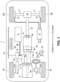
- FIG. 1 shows an automobile 1 (an example of the vehicle) to which the disclosed technique is applied.
- the automobile 1 is a hybrid automobile (or a hybrid vehicle) capable of traveling using electric power.
- the automobile 1 has wheels, particularly a total of four wheels, including front wheels 2F and rear wheels 2R.
- Friction brakes 31 are respectively attached to the front wheels 2F and the rear wheels 2R in order to apply braking on rotations of the front wheels 2F and the rear wheels 2R.
- the engine 4 may be disposed on a front side of a vehicle body and the drive wheels are arranged on a rear side of the vehicle body.
- the automobile 1 is a so-called FR vehicle.
- the engine 4 is an internal combustion engine which burns fossil fuel.
- the engine 4 may also be a so-called 4-cycle engine which generates rotative power by repeating the respective cycles of intake, compression, expansion, and exhaust. While the engine 4 is available in various types or modes such as a spark-ignited engine and a compression-ignited engine, the type or the mode of the engine 4 is not particularly limited in the disclosed technique.
- the engine 4 is disposed approximately in a center part in a vehicle width direction in a state where a crankshaft 4a which outputs rotative power is oriented in a front-rear direction of the vehicle body.
- Various apparatuses and mechanisms associated with the engine 4 such as an intake system, an exhaust system, and a fuel supply system may be installed in the automobile 1.
- the motor 5 may be a permanent magnet-type synchronous motor which is driven by a three-phase AC current.
- the motor 5 may be serially disposed to the rear of the engine 4 via the K0 clutch 6.
- the motor 5 is also serially disposed to the front of the automatic transmission 8.
- the K0 clutch 6 may be installed so as to be interposed between a front end part of a shaft 5a of the motor 5 and the crankshaft 4a of the engine 4.
- the K0 clutch 6 switches between a state (connected state or engaged state) in which the crankshaft 4a and the shaft 5a are connected to each other and a state (separated state or disengaged state) in which the crankshaft 4a and the shaft 5a are separated from each other.
- a rear end part of the shaft 5a of the motor 5 may be connected to an input shaft 8a of the automatic transmission 8. Therefore, the engine 4 is connected to the automatic transmission 8 via the K0 clutch 6 and the shaft 5a. By putting the K0 clutch 6 in the separated state, the engine 4 is detached from the automatic transmission 8.
- the K0 clutch 6 is switched between the connected state and the separated state. For example, during deceleration of the automobile 1, regeneration may be performed in a state where the K0 clutch 6 is switched to the separated state and the engine 4 is detached.
- the motor 5 is connected via the inverter 7 and a high-voltage cable 40 to the high-voltage battery 9 which is mounted as a drive power source.
- a DC battery with a rated voltage of 50 V or lower or, specifically, a 48 V DC battery may be used as the high-voltage battery 9.
- the high-voltage battery 9 supplies high-voltage DC electric power to the inverter 7.
- the inverter 7 may convert the DC electric power into 3-phase AC and feeds the converted power to the motor 5. Accordingly, the motor 5 is rotatively driven. In addition, the motor 5 supplies regenerative energy to the high-voltage battery 9.
- the high-voltage battery 9 may also be connected to a DC-DC converter 10 via the high-voltage cable 40.
- the DC-DC converter 10 converts high-voltage DC electric power of 48 V into low-voltage DC electric power of 12 V and outputs the converted low-voltage DC electric power.
- the DC-DC converter 10 (an output side thereof) is connected to a low-voltage battery 11 (a so-called lead-acid battery) via a low-voltage cable 41.
- the low-voltage battery 11 may be connected to various electrical components via the low-voltage cable 41.
- the DC-DC converter 10 may also be connected to a CAN 12 (Controller Area Network) via the low-voltage cable 41. Accordingly, the DC-DC converter 10 supplies low-voltage DC electric power to the CAN 12.
- CAN 12 Controller Area Network
- the automatic transmission 8 is a hydraulically controlled multi-stage automatic transmission or a hydraulically controlled multi-speed automatic transmission (a so-called AT).
- the automatic transmission 8 has the input shaft 8a to be connected to the engine 4 and an output shaft 8b to be connected to drive wheels (the rear wheels 2R) of the automobile 1.
- the automatic transmission 8 is capable of gear-shifting or speed-changing a rotation input to the input shaft 8a by a transmission gear ratio corresponding to a shift stage or a gear selected particularly by an occupant and outputting the gear-shifted or speed-changed rotation.
- the input shaft 8a is disposed in a front end part of the automatic transmission 8. As described above, the input shaft 8a is connected to the shaft 5a of the motor 5.
- the output shaft 8b may be disposed in a rear end part of the automatic transmission 8. The output shaft 8b rotates independently of the input shaft 8a.
- a transmission mechanism comprised of a torque converter 8c, a plurality of planetary gear mechanisms, a plurality of friction fastening elements (or friction engaging elements), and the like may be built in between the input shaft 8a and the output shaft 8b.
- Each friction fastening element (or friction engaging element) is switched between a fastened state (or an engaged state) and a non-fastened state (or a disengaged state) by hydraulic pressure.
- FIG. 2 shows a fastening table (or an engaging table) of the automatic transmission 8.
- a circle sign in the table indicates fastening or engaging.
- Three clutches including the first clutch CL1, the second clutch CL2, and the third clutch CL3 and two brakes including the first brake BR1 and the second brake BR2 are incorporated into the automatic transmission 8 as friction fastening elements (or friction engaging elements).
- the automatic transmission 8 selects and fastens (or engages) three elements from among the three clutches and the two brakes according to hydraulic control. Accordingly, the shift stage of the automatic transmission may be switched to any one of forward shift stages from 1st speed to 8th speed and a reverse shift stage (reverse speed).
- the 1st speed is formed by fastening (or engaging) of the first clutch CL1, the first brake BR1, and the second brake BR2.
- a 2nd speed is formed by fastening of the second clutch CL2, the first brake BR1, and the second brake BR2.
- a 3rd speed is formed by fastening of the first clutch CL1, the second clutch CL2, and the second brake BR2.
- a 4th speed is formed by fastening of the second clutch CL2, the third clutch CL3, and the second brake BR2.
- a 5th speed is formed by fastening of the first clutch CL1, the third clutch CL3, and the second brake BR2.
- a 6th speed is formed by fastening of the first clutch CL1, the second clutch CL2, and the third clutch CL3.
- a 7th speed is formed by fastening of the first clutch CL1, the third clutch CL3, and the first brake BR1.
- the 8th speed is formed by fastening of the second clutch CL2, the third clutch CL3, and the first brake BR1.
- the reverse speed is formed by fastening of the third clutch CL3, the first brake BR1, and the second brake BR2.
- Shifting up to the 5th and higher speeds is performed in a similar manner. Shifting down involves an opposite procedure to the switching performed when shifting up.
- the automatic transmission 8 may be shifted to neutral during deceleration of the automobile 1. Specifically, when the automatic transmission 8 is in the 2nd speed, the 3rd speed, or the 4th speed, the automatic transmission 8 is shifted to neutral by opening the second clutch CL2. In addition, when the automatic transmission 8 is in the 5th speed, the 6th speed, the 7th speed, or the 8th speed, the automatic transmission 8 is shifted to neutral by opening the third clutch CL3.
- the second clutch CL2 and the third clutch CL3 may be collectively referred to as a K1 clutch. Opening the K1 clutch during deceleration of the automobile 1 means interrupting or disconnecting motive power transmission between the input shaft 8a and the output shaft 8b of the automatic transmission 8 and shifting the automatic transmission 8 to neutral.
- the output shaft 8b of the automatic transmission 8 may be connected to a differential gear 16 via a propeller shaft 15 which extends in the front-rear direction of the vehicle body.
- a pair of drive shafts 17 which extend in a vehicle width direction and which is connected to the left and right rear wheels 2R, 2R are connected to the differential gear 16. Rotative power output through the propeller shaft 15 is distributed by the differential gear 16 and then transmitted to each rear wheel 2R though the pair of drive shafts 17, 17.
- FIG. 3A is a block diagram of a gear-shifting control apparatus.
- the controller 20 described above is installed in the automobile 1 in order to control the engine 4, the motor 5, the K0 clutch 6, the automatic transmission 8, the friction brake system 3, and the like according to operations by the driver and to control traveling of the automobile 1.
- the controller 20 is comprised of hardware including, e.g., a processor, a memory, and an interface and software including a database and a control program. Note that, while one controller 20 is shown in the gear-shifting control apparatus shown in FIG.
- the controller of the gear-shifting control apparatus may be divided into a unit (Powertrain Control Module or PCM) which mainly controls operations of the drive sources (the engine 4 and the motor 5) and a unit (Transmission Control Module or TCM) which mainly controls operations of the K0 clutch 6 and the automatic transmission 8.
- PCM Powertrain Control Module
- TCM Transmission Control Module
- the PCM and the TCM are connected by the CAN 12 and are configured to be capable of performing telecommunications with each other.
- the PCM further functions as a brake ECU (Electronic Control Unit) for controlling the friction brake system 3.
- the brake ECU may be separated from the PCM.
- the gear-shifting control apparatus may be equipped with sensors which measure various parameters related to traveling of a vehicle.
- the gear-shifting control apparatus may be equipped with a vehicle speed sensor 51, a wheel speed sensor 52, a steering angle sensor 53, a yaw rate sensor 54, a brake pedal sensor 55, an accelerator opening sensor 56, an AT input torque sensor 57, and an AT input rotation speed sensor 58.
- the vehicle speed sensor 51 outputs a signal corresponding to a vehicle speed of the automobile 1.
- the wheel speed sensor 52 outputs a signal corresponding to the rotation speed of each wheel among the four wheels 2F and 2R of the automobile 1.
- the steering angle sensor 53 outputs a signal corresponding to a rotation angle of a steering wheel 110 (refer to FIG. 1 ) operated by the driver or, in other words, a steering angle.
- the yaw rate sensor 54 outputs a signal corresponding to a yaw rate of the automobile 1.
- the brake pedal sensor 55 outputs a signal corresponding to depressing of a brake pedal 19 (refer to FIG. 1 ) operated by the driver.
- the accelerator opening sensor 56 outputs a signal corresponding to depressing of an accelerator pedal 18 (refer to FIG. 1 ) operated by the driver.
- the AT input torque sensor 57 outputs a signal corresponding to an input torque of the input shaft 8a of the automatic transmission 8.
- the AT input rotation speed sensor 58 outputs a signal corresponding to the rotation speed of the input shaft 8a of the automatic transmission 8.
- the controller 20 receives, via the CAN 12, signals output by the sensors.
- the controller 20 outputs control signals to the engine 4, the inverter 7, the K0 clutch 6, the automatic transmission 8, and the friction brake system 3 through the CAN 12. Accordingly, the controller 20 controls the engine 4, the motor 5, the K0 clutch 6, the automatic transmission 8, and the friction brake system 3.
- the controller 20 can execute gear-shifting control of changing a shift stage of the automatic transmission 8.
- the gear-shifting control involves changing the shift stage of the automatic transmission 8 by outputting a gear-shifting signal according to the rotation speed of the input shaft 8a to the automatic transmission 8.
- the controller 20 may execute the change in the shift stage after adjusting a difference in rotation speed between the input shaft 8a and the output shaft 8b.
- the controller 20 starts the gear-shifting control (more accurately, the adjustment of a difference in rotation speed between the input shaft 8a and the output shaft 8b), triggered by the number of rotation speed of the input shaft 8a dropping to a predetermined shift-down point, particularly at an occasion of a shift-down of the shift stage.
- a shift-down point may also be simply referred to as a "gear-shifting point”.
- the controller 20 is also capable of controlling the friction brake system 3.
- the friction brake system 3 distributes a braking force to the front wheels 2F and the rear wheels 2R of the automobile 1 so that braking is realized particularly upon an operation of the brake pedal 19 by the driver.
- the friction brake system 3 is a hydraulically controlled friction brake system.
- a level of the hydraulic pressure corresponds to a level of the braking force distributed by the friction brakes 31. Specifically, when the hydraulic pressure is low, the braking force is low as compared to when the hydraulic pressure is high.
- the controller 20 is also capable of executing regeneration control for performing regeneration of energy.
- the regeneration control involves performing regeneration according to at least one of distribution of a braking force by the friction brake system 3 and impartment of a regenerative braking torque to the rear wheels 2R by the motor 5.
- the controller 20 is also capable of performing regeneration particularly by coordination between the distribution of a braking force and the impartment of a regenerative braking torque. Note that even cases where the friction brake system 3 is not involved in regeneration such as during a non-operation of the brake pedal 19 are also included in "regeneration control" as referred to herein.
- the controller 20 is capable of executing the gear-shifting control and the regeneration control during deceleration of the automobile 1.
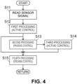
- FIG. 4 shows an entirety of control related to behavioral stability of the automobile 1. Note that the flows shown in FIG. 4 and FIGS. 6 , 8 to 11 , and 15 to be described later are basically related to control during deceleration of the automobile 1.
- the controller 20 executes regenerative coordination control or second regeneration control as the regeneration control depending on whether or not the driver is depressing the brake pedal 19. These types of regeneration correspond to so-called “decelerative regeneration”.
- the controller 20 may execute regenerative coordination control in which a part of a required braking force of the driver is covered by a regenerative braking torque of the motor 5.
- the controller 20 may execute second regeneration control in which regenerative braking corresponding to engine braking is performed.
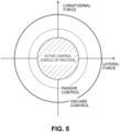
- FIG. 5 shows a concept of functions of control related to the behavioral stability of the automobile 1.
- the automobile 1 has three functions, namely, active control, passive control, and DSC/ABS control. Active control functions so as to keep a grip force of the wheels 2F and 2R within a circle of friction illustrated in FIG. 5 .
- the behavioral stability of the automobile 1 is maintained as long as the grip force of the wheels 2F and 2R stay within the circle of friction.
- Active control is control for maintaining the behavioral stability of the automobile 1.
- Passive control functions to return the grip force of the wheels 2F and 2R into the circle of friction when the grip force of the wheels 2F and 2R exceeds the circle of friction and the behavior of the automobile 1 becomes unstable.
- DSC/ABS control functions to return the grip force of the wheels 2F and 2R into the circle of friction when the behavior of the automobile 1 is about to diverge or, in other words, when the grip force of the wheels 2F and 2R is about to exceed a circle with a largest diameter by having the friction brake system 3 impart a braking force to each of the wheels 2F and 2R through the friction brakes 31.
- Known techniques can be adopted for the DSC/ABS control.
- step S11 after start of the process, the controller 20 reads a sensor signal.
- the controller 20 determines a traveling state of the automobile 1.
- step S12 the controller 20 executes first processing (step S12).
- the first processing is related to active control and switches gear-shifting control according to a road surface ⁇ . Details of the first processing will be provided later.
- step S13 the process makes a transition to second processing (step S13) or fourth processing (step S15).
- the second processing is related to passive control and to gear-shifting control when the automobile 1 falls into an oversteered state. Details of the second processing will be provided later.
- step S13 the process makes a transition to third processing (step S14) or the fourth processing (step S15).
- the third processing is related to active control and switches gear-shifting control according to a slip state of the wheels 2F and 2R. Details of the third processing will be provided later.
- the fourth processing is DSC/ABS control. Details of the fourth processing will be provided later.
- FIG. 6 is a flow chart of the first processing.
- the first processing is related to active control.
- the first processing is processing which is performed "when the automobile 1 is not in an oversteered state".
- the controller 20 can prevent an occurrence of an oversteered state in advance.
- step S21 after start of the process, the controller 20 determines whether or not the road surface ⁇ of a road surface on which the automobile 1 travels is lower than a predetermined threshold (whether or not a determination of Low is made).
- the controller 20 sets the gear-shifting point (shift-down point) higher in a state of deceleration of the vehicle during a brake pedal operation (during an operation of the brake pedal 19) than a state of deceleration of the vehicle during a non-brake pedal operation (during a non-operation of the brake pedal 19) under the same condition of the road surface ⁇ .
- step S22 the controller 20 determines whether or not the driver is depressing the brake pedal 19 (whether or not brakes are applied).
- the determination in step S22 can be performed based on a signal of the brake pedal sensor 55.
- a result of the determination in step S22 is Yes or, in other words, when the driver is depressing the brake pedal 19 (when it is determined that a brake pedal operation is being performed)
- the process advances to step S23.
- a result of the determination in step S22 is No or, in other words, when the driver is not depressing the brake pedal 19 (when it is determined that a non-brake pedal operation is being performed)
- the process advances to step S24.
- step S23 the controller 20 selects a first gear-shifting point S1 as a shift-down point of the automatic transmission 8.
- FIG. 7 illustrates a shift-down point for each shift stage of the automatic transmission 8.
- an abscissa represents a vehicle speed and an ordinate represents the rotation speed of the input shaft 8a of the automatic transmission 8.
- the first gear-shifting point S1 selected in step S23 is set to a constant rotation speed of the input shaft 8a regardless of the vehicle speed with respect to each shift stage.
- the first gear-shifting point S1 is higher than a second gear-shifting point S2 and a third gear-shifting point S3 to be described later.
- the rotation speed of the input shaft 8a of the automatic transmission 8 reaches the first gear-shifting point S1 when the vehicle speed is about less than 60 km/h.
- the automatic transmission 8 shifts down from the 6th speed to the 5th speed.
- the rotation speed of the input shaft 8a of the automatic transmission 8 or, in other words, the rotation speed of the motor 5 (the output rotation speed) becomes higher than the first gear-shifting point S1.
- the rotation speed of the motor 5 performing a regeneration operation can be maintained at a high level by setting the shift-down point to the first gear-shifting point S1 as compared to a case where the shift-down point is set to the second gear-shifting point S2 or the third gear-shifting point S3.
- a high rotation speed of the motor increases a regeneration amount and, therefore, improves the fuel efficiency performance of the automobile 1.
- step S24 to which the process advances when the brake pedal 19 is not depressed, the controller 20 selects the second gear-shifting point S2 which is set lower than the first gear-shifting point S1 as the shift-down point of the automatic transmission 8.
- the controller 20 when the driver is not depressing the brake pedal 19, the controller 20 does not perform the regenerative coordination control in the sense that the friction brake system 3 does not contribute toward regeneration. In this case, a regeneration operation is performed by having the motor 5 impart a regenerative braking torque corresponding to engine braking to the rear wheels 2R. In a decelerating state where the driver is not depressing the brake pedal 19, a change to an acceleration request may occur when the driver depresses the accelerator pedal 18. When the rotation speed of the input shaft 8a of the automatic transmission 8 is maintained at a high level due to setting the shift-down point to the first gear-shifting point S1, there is a risk that a sufficient drive force cannot be secured upon the acceleration request by the driver.
- the controller 20 selects the second gear-shifting point S2 as the shift-down point.
- the second gear-shifting point S2 is set to a constant rotation speed of the input shaft 8a regardless of the vehicle speed with respect to each shift stage in a similar manner to the first gear-shifting point S1.
- the second gear-shifting point S2 is set lower than the first gear-shifting point S1 regardless of the vehicle speed.
- the first gear-shifting point S1 and the second gear-shifting point S2 are both gear-shifting points which are selected when the road surface ⁇ is relatively high. Therefore, comparing the first gear-shifting point S1 and the second gear-shifting point S2 with each other equates to a comparison under the same condition of the road surface ⁇ .
- the wheels 2F and 2R are likely to slip.
- the grip force of the wheels 2F and 2R is apt to exceed the circle of friction and the behavior of the automobile 1 tends to become unstable.
- the controller 20 executes control for preventing the behavior of the automobile 1 from becoming unstable due to a gear-shifting operation of the automatic transmission 8.
- step S26 the controller 20 limits or prohibits a shift-up which causes the shift stage to be changed to a predetermined stage or higher.
- the controller 20 prohibits shift-ups which cause the shift stage to be changed to the 7th and higher speeds such as a shift-up from the 6th speed to the 7th speed and a shift-up from the 7th speed to the 8th speed. Therefore, when the process advances to step S26, the automatic transmission 8 is temporarily shifted up to the 6th speed at a maximum.
- a frequency of shift-downs when a transition is made from acceleration to deceleration can be reduced. Accordingly, opportunities for the behavior of the automobile 1 to become unstable such as an occurrence of oversteering decrease.
- step S27 in other words, during deceleration of the vehicle when it is determined that the road surface ⁇ is lower than the predetermined threshold in the regeneration control, the controller 20 sets the shift-down point lower than during deceleration of the vehicle when it is determined that the road surface ⁇ is equal to or higher than the threshold. In other words, the controller 20 sets the shift-down point lower as the road surface ⁇ becomes lower.
- the automatic transmission 8 performs a shift-down as the vehicle speed and/or the rotation speed of the input shaft 8a of the automatic transmission 8 decreases.
- the controller 20 performs the shift-down in a state where the vehicle speed is as low as possible.
- the controller 20 selects the third gear-shifting point S3 which is set lower than both the first gear-shifting point S1 and the second gear-shifting point S2 as a downshift point of the automatic transmission 8.
- the third gear-shifting point S3 is set to a constant rotation speed of the input shaft 8a regardless of the vehicle speed with respect to each shift stage in a similar manner to the first gear-shifting point S1 and the second gear-shifting point S2.
- the third gear-shifting point S3 is set lower than the first gear-shifting point S1 and the second gear-shifting point S2 regardless of the vehicle speed. Comparing the first gear-shifting point S1 and the second gear-shifting point S2 with the third gear-shifting point S3 equates to a comparison under different conditions of the road surface ⁇ .
- the highest-speed stage is limited to the 6th speed when a transition is made from acceleration to deceleration.
- the shift-down point is the third gear-shifting point S3 which is set relatively low. Therefore, in step S27, the automatic transmission 8 does not perform a shift-down until the vehicle speed drops to around 40 km/h as indicated by a blank arrow in FIG. 7 . Since a shift-down at a high vehicle speed is not performed, the behavior of the automobile 1 can be prevented from changing or becoming unstable.
- the controller 20 interrupts or disconnects motive power transmission between the input shaft 8a and the output shaft 8b.
- step S28 which follows step S27, the controller 20 opens the K1 clutch in response to the rotation speed of the input shaft 8a of the automatic transmission 8 falling to the third gear-shifting point S3.
- the K1 clutch is a clutch comprised of friction fastening elements of the automatic transmission 8.
- the motive power transmission between the input shaft 8a and the output shaft 8b of the automatic transmission 8 is interrupted or disconnected. Since opening of the K1 clutch reduces a torque which acts on the rear wheels 2R, destabilization of the behavior of the automobile 1 can be suppressed and, at the same time, engine stall due to a further decrease in the rotation speed of the engine 4 can be avoided.
- the controller 20 is configured to select one of a plurality of gear-shifting maps based on the operational state of the automobile 1.
- the plurality of gear-shifting maps are stored in a memory and used by being read by the controller 20 when appropriate.
- the controller 20 is configured to refer to a regeneration request map M3, a combustion request map M1, and a travel request map M2 as the plurality of gear-shifting maps.
- the regeneration request map M3 corresponds to a map (a third map) which is used during regenerative coordination control or, in other words, when the friction brake system 3 and the motor 5 perform decelerative regeneration by working in a coordinated manner.
- the maps are at least related to a shift-down among a shift-down and a shift-up and define a plurality of gear-shifting points which correspond to each shift stage.
- Each gear-shifting point indicates a threshold of the rotation speed of the input shaft 8a which triggers gear-shifting.
- each gear-shifting point is defined on a high-rotation-speed side (or a higher-rotation-speed side) than both the combustion request map M1 and the travel request map M2.
- the rotation speed of the input shaft 8a is set so as to be kept high as compared to both the combustion request map M1 and the travel request map M2 (or both the rotation speeds of the input shaft 8a of the combustion request map M1 and the travel request map M2).
- each gear-shifting point is defined on a further low-rotation-speed side (a further lower-rotation-speed side) than the travel request map M2 (or a gear-shifting point of the travel request map M2).
- the rotation speed of the input shaft 8a is kept lower than the regeneration request map M3 (or the rotation speed in the regeneration request map M3), the rotation speed of the input shaft 8a is kept higher than the combustion request map M1 (or the rotation speed in the combustion request map M1).
- the controller 20 uses gear-shifting points defined in each map as a base set of gear-shifting points.
- the first gear-shifting point S1, the second gear-shifting point S2, and the third gear-shifting point S3 described earlier are to be used in place of such a base set.
- step S28 when the process advances to step S28, the shift-down point is set to the third gear-shifting point S3 instead of a value of a base set defined in each map.
- step S23 the controller 20 sets the shift-down point to the first gear-shifting point S1 instead of a value of a base set defined in each map.
- step S24 the shift-down point is set to the second gear-shifting point S2 instead of a value of a base set defined in each map.
- the first gear-shifting point S1, the second gear-shifting point S2, and the third gear-shifting point S3 are set so as to assume same values for each map regardless of which of the three maps has been referred to by the controller 20.
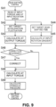
- FIG. 8 is a flow chart of the second processing.
- the second processing is passive control.
- the controller 20 determines whether or not a determination of oversteering has been made. For example, the controller 20 determines whether or not the automobile 1 is in an oversteered state based on a deviation between an estimated yaw rate which can be calculated from the vehicle speed and the steering angle and an actual yaw rate based on a signal of the yaw rate sensor 54. The controller 20 may determine that the automobile 1 is in an oversteered state when the deviation between the estimated yaw rate and the actual yaw rate is equal to or larger than a predetermined value.
- step S31 When a result of the determination in step S31 is No or, in other words, when the automobile 1 is not in an oversteered state, passive control is not performed. The process advances to the third processing. On the other hand, when the result of the determination in step S31 is Yes or, in other words, when the automobile 1 is in an oversteered state, the process advances to step S32.
- step S32 the controller 20 determines whether or not brake regeneration is being performed. In other words, a determination of whether or not the driver is depressing the brake pedal 19 is made.
- a result of the determination in step S32 is Yes, the process makes a transition to step S33, but when the result of the determination in step S32 is No, the process advances to step S34 without making a transition to step S33.
- regenerative coordination control in which a part of a required braking force of the driver is covered by a regenerative braking torque of the motor 5 is executed.
- the regenerative braking torque of the motor 5 is only imparted to the rear wheels 2R of the automobile 1 which is a rear wheel-drive vehicle. Therefore, a lateral force of the rear wheels 2R decreases and the behavior of the automobile 1 is apt to fall into an oversteered state.
- step S33 the controller 20 executes torque-increase control. Specifically, an input torque of the input shaft 8a of the automatic transmission 8 is increased so as to eliminate the regenerative braking torque of the motor 5 having so far covered for a part of the braking force of the friction brakes 31.
- the torque-increase control corresponds to an end of the regenerative coordination control.
- the friction brake system 3 compensates for a braking force corresponding to the eliminated regenerative braking torque by the braking force of the friction brakes 31. Note that, even after the regenerative coordination control ends, a regenerative braking torque corresponding to engine braking which accompanies releasing the accelerator remains and the regeneration operation of the motor 5 itself continues. Since a regeneration amount is secured even when the automobile 1 is in an oversteered state, an advantage is gained in terms of improving fuel efficiency performance of the automobile 1.
- step S35 the controller 20 determines whether or not the automatic transmission 8 is not gear-shifting (in other words, non-gear-shifting).
- the process advances to step S36.
- the automatic transmission 8 is gear-shifting (in other words, in a case of No)
- the process advances to step S310.
- step S37 the controller 20 determines whether or not the oversteered state of the automobile 1 has been resolved.
- the controller 20 may determine that the oversteered state of the automobile 1 has been resolved when the deviation between the estimated yaw rate and the actual yaw rate falls below the predetermined value.
- the process advances to the fourth processing.
- the process advances to step S38.
- step S38 the controller 20 determines whether or not the rotation speed of the input shaft 8a of the automatic transmission 8 has reached the third gear-shifting point S3.
- the process advances to step S39, but when the rotation speed of the input shaft 8a has not reached the third gear-shifting point S3, the process advances to the fourth processing.
- the third gear-shifting point S3 is a shift-down point which takes an engine stall into consideration.
- step S39 the controller 20 opens the K1 clutch of the automatic transmission 8 in a similar manner to step S28 of the first processing. Accordingly, an engine stall can be suppressed. Subsequently, the process advances to the fourth processing.
- step S35 when the automobile 1 is in an oversteered state and the automatic transmission 8 is performing a shift-down (a case where the result of step S35 is No) or when a delayed shift-down is performed after the oversteered state of the automobile 1 is resolved (a case where the result of step S34 is No), the controller 20 executes gear-shifting control upon a determination of oversteering in step S310. Details of the gear-shifting control will be provided later. In simple terms, a torque of the rear wheels 2R fluctuates due to inertia of the automatic transmission 8 which accompanies a shift-down.
- an input torque of the input shaft 8a of the automatic transmission 8 is increased as compared to during normal gear-shifting control or, in other words, an input torque during a non-determination of oversteering so that a torque fluctuation of the rear wheels 2R corresponding to the amount of inertia is suppressed.
- a torque fluctuation is suppressed even when a shift-down is performed and destabilization of the behavior of the automobile 1 attributable to the shift-down is prevented from deteriorating.
- step S311 the controller 20 determines whether or not brake regeneration is being performed, and when a result of the determination is Yes meaning that brake regeneration is being performed, the process advances to step S312. On the other hand, when the result of the determination is No meaning that brake regeneration is not being performed, the process advances from step S311 to the fourth processing.
- step S312 the controller 20 stops the regenerative coordination control, secures, with the friction brakes 31, the braking force having been covered by the regenerative braking torque of the motor 5, and achieves deceleration commensurate with braking requested by the driver. Note that, even after the regenerative coordination control ends, a regenerative braking torque corresponding to engine braking which accompanies releasing the accelerator remains and the regeneration operation of the motor 5 itself continues.
- FIG. 9 is a flow chart of gear-shifting control.
- the controller 20 reads an AT input torque and the AT input rotation speed. The process subsequently advances to each of step S42 and step S44.
- step S42 the controller 20 sets a target acceleration fluctuation during gear-shifting of the automatic transmission 8.
- the target acceleration fluctuation is a target value of an acceleration fluctuation which is created in the automobile 1 during gear-shifting of the automatic transmission 8.
- the target acceleration fluctuation is set such that the higher the AT input rotation speed, the larger the target acceleration fluctuation.
- the target acceleration fluctuation is determined according to a shift stage and the AT input rotation speed of the automatic transmission 8 based on a relational expression or a map set with respect to each of a shift-up and a shift-down.
- the controller 20 calculates an AT output torque from the set target acceleration fluctuation.
- the AT output torque is a torque fluctuation of the output shaft 8b during gear-shifting of the automatic transmission 8.
- step S44 the controller 20 sets a target gear-shifting time during gear-shifting of the automatic transmission 8.
- the target gear-shifting time is set such that the higher the AT input rotation speed, the shorter the target gear-shifting time.
- the target gear-shifting time is determined from the shift stage and the AT input rotation speed of the automatic transmission 8 based on a relational expression or a map set with respect to each of a shift-up and a shift-down.
- step S45 the controller 20 calculates an AT input rotation gradient from the set target gear-shifting time.
- the AT input rotation gradient is a change rate of the rotation speed of the input shaft 8a during gear-shifting of the automatic transmission 8.
- step S46 the controller 20 determines whether or not a correction of the calculated AT output torque and/or the calculated AT input rotation gradient is necessary.
- the controller 20 determines that a correction is necessary.
- the process advances to step S47 and a correction of the calculated AT output torque and/or the calculated AT input rotation gradient is performed.
- step S48 the process advances to step S48 instead of advancing to step S47.
- step S54 even in first coordinated gear-shifting control in step S54 and in second coordinated gear-shifting control in step S55 of the third processing to be described later, the correction of step S47 is executed and the torque fluctuation of the rear wheels 2R during gear-shifting is suppressed.
- step S48 the controller 20 calculates the AT input torque based on the AT output torque and the AT input rotation gradient.
- the AT input torque is a torque input to the input shaft 8a of the automatic transmission 8 and the AT input torque is mainly adjusted by the motor 5.
- an amount of increase of the AT input torque is increased as compared to an amount of increase during a normal shift-down (in other words, during a non-determination of an oversteered state and without any correction).
- step S49 the controller 20 calculates hydraulic pressure to be supplied to the friction fastening elements of the automatic transmission 8 so as to correspond to the calculated AT input torque.
- the automatic transmission 8 performs a shift-down or a shift-up due to the friction fastening elements being supplied with the hydraulic pressure.
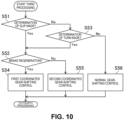
- FIG. 10 is a flow chart of the third processing.
- the third processing is active control.
- the controller 20 determines whether or not a slip determination has been made.
- the controller 20 may determine a slip state of each of the wheels 2F and 2R based on, for example, the vehicle speed and the wheel speed.
- a result of the determination in step S51 is Yes or, in other words, when it is determined that the wheels 2F and 2R are slipping
- the process advances to step S52
- the result of the determination in step S51 is No or, in other words, when it is determined that the wheels 2F and 2R are not slipping
- the process advances to step S53.
- step S53 the controller 20 determines whether or not a turn determination has been made.
- the controller 20 may determine a turn state of the automobile 1 based on, for example, the steering angle and the yaw rate.
- a result of the determination in step S53 is Yes or, in other words, when it is determined that the automobile 1 is in a turn state
- the process advances to step S52
- the result of the determination in step S53 is No or, in other words, when it is determined that the automobile 1 is not in a turn state
- the process advances to step S56.
- step S56 the controller 20 executes normal gear-shifting control. In other words, since the wheels 2F and 2R are not in a slip state and the automobile 1 is in a state of straight travel, it is unlikely that the automobile 1 will become unstable during gear-shifting of the automatic transmission 8. In step S56, the correction of step S47 in the flow of the gear-shifting control shown in FIG. 9 is not performed.
- steps S52, S54, and S55 the wheels 2F and 2R are in a slip state or the automobile 1 is in a turn state, and when the automatic transmission 8 performs gear-shifting in this state and a torque of the rear wheels 2R fluctuates, there is a risk that the behavior of the automobile 1 may become unstable.
- the controller 20 performs control for preventing the behavior of the automobile 1 from becoming unstable.
- step S52 the controller 20 determines whether or not brake regeneration is being performed.
- the process advances to step S54.
- the process advances to step S55.
- the controller 20 executes coordinated control of the friction brake system 3, the motor 5, and the automatic transmission 8. Specifically, in step S54, the automatic transmission 8 executes gear-shifting control so that the torque fluctuation of the rear wheels 2R which accompanies gear-shifting is suppressed. In step S54, the correction of step S47 in the flow of the gear-shifting control shown in FIG. 9 is performed. In addition, the friction brake system 3 and/or the motor 5 impart a torque to the rear wheels 2R so as to compensate for the torque fluctuation during gear-shifting. As a result, the behavior of the automobile 1 is prevented from becoming unstable.
- step S55 the automatic transmission 8 executes gear-shifting control so that the torque fluctuation of the rear wheels 2R which accompanies gear-shifting is suppressed. Even in step S55, the correction of step S47 in the flow of the gear-shifting control shown in FIG. 9 is performed.
- the motor 5 imparts a torque to the rear wheels 2R so as to compensate for the torque fluctuation during gear-shifting. As a result, the behavior of the automobile 1 is prevented from becoming unstable.
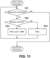
- FIG. 11 is a flow chart of the fourth processing.
- the fourth processing is DSC/ABS control.
- step S61 after the start of the process, the controller 20 determines whether or not an unstable behavior of the automobile 1 is diverging. When an unstable behavior of the automobile 1 is diverging, the process advances to step S62. When an unstable behavior of the automobile 1 is not diverging, since DSC/ABS control is unnecessary, the fourth processing is ended.
- step S62 the controller 20 determines whether or not brakes are applied.
- the process advances to step S63, but when the driver is not depressing the brake pedal 19 (in other words, when the result of the determination is No), the process advances to step S64.
- step S63 since the brakes are applied, DSC control or ABS control is executed to cause the unstable behavior of the automobile 1 to converge.
- step S64 since the brakes are not applied, DSC control is executed to cause the unstable behavior of the automobile 1 to converge.
- step S63 or step S64 the fourth processing ends.
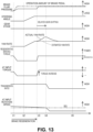
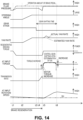
- Each time chart includes changes in a brake pedal operation amount and brake fluid pressure, a change in a steering angle (a measured value of the steering angle sensor 53), a change in a gear stage, a change in a yaw rate (a measured value of the yaw rate sensor 54), a change in a regenerative braking torque, a change in the AT input torque, a change in a transmission ratio of the automatic transmission 8, and a change in the AT input rotation speed.
- FIG. 12 is a time chart in a case where a shift-down of the automatic transmission 8 is prohibited until an oversteered state of the automobile 1 is resolved.
- the driver starts to depress the brake pedal 19.
- the controller 20 starts regenerative coordination control.
- the friction brake system 3 reduces brake fluid pressure with respect to an operation amount of the brake pedal 19 which is indicated by a long dashed dotted line.
- a braking force of the friction brakes 31 decreases by a corresponding amount.
- the motor 5 increases a regenerative braking torque so as to compensate for the decreased amount of the braking force of the friction brakes 31. Accordingly, since regenerative energy can be secured, an advantage is gained in terms of improving fuel efficiency of the automobile 1. Since the regenerative braking torque increases, a torque input to the input shaft 8a of the automatic transmission 8 decreases.
- the driver starts to steer the steering wheel 110. Accordingly, the steering angle gradually increases.
- the automobile 1 starts to turn and the yaw rate gradually increases.
- the controller 20 increases the input torque of the input shaft 8a of the automatic transmission 8 so as to eliminate the regenerative braking torque of the motor 5 having so far covered for a part of the braking force of the friction brakes 31 (torque increase, step S33). Accordingly, the regenerative braking torque decreases. Note that, even at the time t3 and thereafter, the regenerative braking torque corresponding to engine braking which accompanies releasing the accelerator remains and the regeneration operation of the motor 5 itself continues. In addition, the hydraulic pressure of the friction brakes 31 is increased so as to compensate for the decrease in the regenerative braking torque of the motor 5.
- the controller 20 causes the automatic transmission 8 to execute the shift-down which has been delayed (a transition from step S34 to step S310). Specifically, the input torque of the input shaft 8a of the automatic transmission 8 is increased as compared to during normal gear-shifting control by increasing the torque of the motor 5 (refer to arrow indicating "increase"). Accordingly, since a torque fluctuation of the rear wheels 2R corresponding to an inertia during the shift-down is suppressed, the behavior of the automobile 1 can be prevented from becoming unstable once again immediately after the resolution of the oversteered state.
- normal gear-shifting control may be executed instead of gear-shifting control upon a determination of oversteering. In other words, an increase in the torque of the motor 5 during the shift-down may be suppressed.
- FIG. 13 is a time chart in a case where a shift-down of the automatic transmission 8 is prohibited until an oversteered state of the automobile 1 is resolved.
- the time chart in FIG. 13 differs from the time chart in FIG. 12 in that the AT input rotation speed reaches the third gear-shifting point S3.
- the controller 20 increases the input torque of the input shaft 8a of the automatic transmission 8 so as to eliminate the regenerative braking torque of the motor 5 having so far covered for a part of the braking force of the friction brakes 31 (torque increase). Accordingly, the regenerative braking torque decreases. Note that, even at the time t3 and thereafter, the regeneration operation of the motor 5 itself continues. Gear-shifting of the automatic transmission 8 is delayed.
- the third gear-shifting point S3 is a shift-down point which takes an engine stall into consideration.
- the controller 20 opens the K1 clutch of the automatic transmission 8. Accordingly, the AT input rotation speed decreases and a transmission ratio which is a velocity ratio between the input shaft 8a and the output shaft 8b of the automatic transmission 8 decreases.
- the oversteered state is resolved by a torque increase of the input shaft 8a.
- the automatic transmission 8 performs a shift-down.
- FIG. 14 is a time chart in a case where the automobile 1 reaches an oversteered state during gear-shifting of the automatic transmission 8. Even in the time chart in FIG. 14 , the driver starts depressing the brake pedal 19 at the time t1 and the driver starts to steer the steering wheel 110 at the time t2 in a similar manner to the time chart in FIG. 12 .
- the controller 20 performs regenerative coordination control.
- the automatic transmission 8 executes a shift-down. Since the automobile 1 is turning, the first coordinated gear-shifting control of the third processing (step S54) is executed. As illustrated in FIG. 14 , the hydraulic pressure of the friction brakes 31 is adjusted at the time t4 or thereafter in accordance with the shift-down of the automatic transmission 8.
- the automobile 1 reaches an oversteered state.
- the controller 20 increases the input torque of the input shaft 8a of the automatic transmission 8 (torque increase) and, at the same time, increases the input torque of the input shaft 8a of the automatic transmission 8 as compared to during normal gear-shifting control by increasing the torque of the motor 5.
- the torque increase for stopping the regenerative coordination control and the torque increase for gear-shifting may be substantially performed at the same time or performed at staggered timings.
- the hydraulic pressure of the friction brakes 31 is increased so as to compensate for the decrease in the regenerative braking torque of the motor 5.
- the motor 5 performs a regeneration operation with a regenerative braking torque corresponding to engine braking.
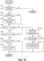
- FIG. 15 shows a modification of the second processing.
- the modification differs from the flow in FIG. 8 in that a shift-down is not delayed.
- the controller 20 determines whether or not a determination of oversteering has been made. When a result of the determination in step S71 is No, passive control is not performed. When a result of the determination in step S71 is Yes, the process advances to step S72.
- step S72 the controller 20 determines whether or not brake regeneration is being performed.
- the process makes a transition to step S73, but when the result of the determination in step S72 is No, the process advances to step S74 without making a transition to step S73.
- step S73 the controller 20 executes torque-increase control. Accordingly, the regenerative coordination control ends. Since the regenerative braking torque having been imparted to the rear wheels 2R decreases and a lateral force of the rear wheels 2R is secured, the oversteered state of the automobile 1 moves toward resolution. After step S73, the process advances to step S74. In step S74 or thereafter, the motor 5 performs a regeneration operation with a regenerative braking torque corresponding to engine braking which accompanies releasing the accelerator. Even when the automobile 1 is in an oversteered state, since as much of a regeneration amount as possible is secured, an advantage is gained in terms of improving fuel efficiency performance of the automobile 1.
- step S74 the controller 20 determines whether or not an unstable behavior of the automobile 1 is diverging. When a result of the determination in step S74 is Yes, the process makes a transition to step S75. When the result of the determination in step S74 is No, the process makes a transition to step S710.
- step S75 the controller 20 determines whether or not the automatic transmission 8 is not gear-shifting.
- the process advances to step S76.
- the automatic transmission 8 is gear-shifting (in other words, in a case of No)
- the process advances to step S710.
- step S76 the controller 20 determines whether or not the rotation speed of the input shaft 8a of the automatic transmission 8 has reached the first gear-shifting point S1.
- the process advances to step S77, but when the rotation speed of the input shaft 8a has not reached the first gear-shifting point S1, the process advances to the fourth processing.
- the first gear-shifting point S1 is a shift-down point when regenerative coordination control is being executed. Note that in step S76, the controller 20 may determine whether or not the rotation speed of the input shaft 8a of the automatic transmission 8 has reached the second gear-shifting point S2.
- step S77 the controller 20 opens the K1 clutch of the automatic transmission 8. Since a shift-down of the automatic transmission 8 is not performed, destabilization of the behavior of the automobile 1 attributable to the shift-down is suppressed.
- step S75 when the automobile 1 is in an oversteered state and the automatic transmission 8 is performing a shift-down (a case where the result of step S75 is No) or when a shift-down is performed after the oversteered state of the automobile 1 is resolved (a case where the result of step S74 is No), the controller 20 executes gear-shifting control upon a determination of oversteering in step S710. Since a torque fluctuation is suppressed even when a shift-down is performed, destabilization of the behavior of the automobile 1 is prevented from deteriorating.
- step S711 the controller 20 determines whether or not brake regeneration is being performed, and when a result of the determination is Yes meaning that brake regeneration is being performed, the process advances to step S712. On the other hand, when the result of the determination is No meaning that brake regeneration is not being performed, the process advances from step S711 to the fourth processing.
- step S712 the controller 20 stops the regenerative coordination control, secures, with the friction brakes 31, the braking force having been covered by the regenerative braking torque of the motor 5, and achieves deceleration commensurate with braking requested by the driver.
- regeneration control is executed by causing the motor 5 to perform a regeneration operation at least during deceleration of the automobile 1. Due to the regeneration control, regenerative energy accumulated in the high-voltage battery 9 increases. A regenerative braking torque produced by the motor 5 is only imparted to the rear wheels 2R through the automatic transmission 8.
- the controller 20 as the controller outputs a gear-shifting signal according to the rotation speed of the input shaft 8a to the automatic transmission 8, triggered by the rotation speed of the input shaft 8a dropping to a predetermined shift-down point.
- the automatic transmission 8 receives the gear-shifting signal and changes the shift stage or, in other words, executes a shift-down of changing the shift stage from a high-speed stage to a low-speed stage.
- a shift stage corresponding to an operational state of the engine 4 is selected.
- the controller 20 sets the shift-down point to the first gear-shifting point S1 or the second gear-shifting point S2 which are relatively high.
- the road surface ⁇ is high, an occurrence of an oversteered state is suppressed even when adopting a configuration in which a shift-down starts on a high-rotation-speed side. Since a regeneration operation on a high-rotation-speed side enables a regeneration amount to be increased as compared to a low-rotation-speed side, a contribution is made toward improving fuel efficiency performance.
- the controller 20 sets the shift-down point to the relatively low third gear-shifting point S3 so that a shift-down is started at a later timing. Accordingly, the gear-shifting control can be started after an oversteered state is avoided or, even if an oversteered state has occurred, the gear-shifting control can be started after the oversteered state is resolved. As a result, the behavior of the automobile 1 can be stabilized and robustness of the vehicle can be improved.
- the gear-shifting control apparatus is capable of achieving both securement of as much of a regeneration amount as possible due to a regeneration operation on a high-rotation-speed side and an improvement in robustness due to delaying a start timing of gear-shifting control.
- step S26 in FIG. 6 during acceleration of the vehicle when the road surface ⁇ is relatively low, a limitation is to be imposed on a highest stage of the shift stages. Accordingly, when the automobile 1 makes a transition from acceleration to deceleration, a frequency of occurrences of a shift-down can be reduced. As a result, opportunities where oversteering may occur can be reduced and the behavior of the automobile 1 can be stabilized.
- step S28 in FIG. 6 when, after the shift-down point is set to the third gear-shifting point S3 based on the road surface ⁇ , the rotation speed of the input shaft 8a drops to the third gear-shifting point S3, the controller 20 interrupts motive power transmission between the input shaft 8a and the output shaft 8b instead of starting gear-shifting. Interrupting the motive power transmission results in a decrease in a torque acting on the rear wheels 2R. Accordingly, destabilization of the behavior of the automobile such as an occurrence of an oversteered state can be suppressed and, at the same time, engine stall due to a further drop in the rotation speed of the engine 4 can be avoided.
- the rotation speed of the motor 5 during a regeneration operation can be maintained at a high level by setting the shift-down point to the relatively high first gear-shifting point S1. Maintaining a high rotation speed of the motor 5 increases a regeneration amount and, eventually, improves fuel efficiency performance of the automobile 1.
- the controller 20 sets the shift-down point of the automatic transmission 8 to the second gear-shifting point S2 which is lower than the first gear-shifting point S1. Accordingly, since the rotation speed of the input shaft 8a of the automatic transmission 8 becomes relatively lower, a sufficient drive force can be secured during the acceleration request by the driver.
- the controller 20 determines an oversteered state of the automobile 1 by receiving signals of the yaw rate sensor 54 which outputs a signal related to a behavior of the automobile 1 and the steering angle sensor 53 which outputs a signal related to a steering operation by the driver.
- the controller 20 determines an oversteered state based on signals of the yaw rate sensor and the steering angle sensor 53. As a result, the controller 20 can determine the behavior of the automobile 1 in a speedy and accurate manner.
- the controller 20 may determine the road surface ⁇ (road surface friction coefficient) of the traveling road of the vehicle based on the acquired wheel speed. Specifically, the controller 20 may first calculate the wheel speed of the non-driven wheels (e.g., front wheels) (the wheel speed sensor may detect the wheel speed of the non-driven wheels). Next, the controller may calculate the slip ratio of the driven wheels based on the wheel speed of the non-driven wheels and the wheel speed of the driven wheels (e.g., rear wheels) (typically detected by the wheel speed sensor). Basically, the larger the difference between the wheel speed of the driven wheels and the wheel speed of the non-driven wheels, the larger the slip ratio of the driven wheels.
- the wheel speed of the non-driven wheels e.g., front wheels
- the controller may calculate the slip ratio of the driven wheels based on the wheel speed of the non-driven wheels and the wheel speed of the driven wheels (e.g., rear wheels) (typically detected by the wheel speed sensor). Basically, the larger the difference between the wheel speed of the driven wheels and the wheel speed of
- the controller 20 may determine the road surface ⁇ based on the slip ratio of the driven wheels and the driving force of the driven wheels.
- a map that defines the road surface ⁇ based on the slip ratio of the driven wheels and the driving force of the driven wheels may be prepared in advance, and the controller refers to such a map to determine and/or acquire the road surface ⁇ corresponding to (or in accordance with) the current slip ratio of the driving wheels and the current driving force of the driven wheels.
- the driving force of the driven wheels may be obtained by multiplying the engine-generated torque, the transmission gear ratio, and the final gear ratio.
Landscapes
- Engineering & Computer Science (AREA)
- Transportation (AREA)
- Mechanical Engineering (AREA)
- Chemical & Material Sciences (AREA)
- Combustion & Propulsion (AREA)
- Automation & Control Theory (AREA)
- Control Of Transmission Device (AREA)
- Regulating Braking Force (AREA)
- Electric Propulsion And Braking For Vehicles (AREA)
- Hybrid Electric Vehicles (AREA)
- Control Of Driving Devices And Active Controlling Of Vehicle (AREA)
Claims (14)
- Fahrzeuggangschaltungssteuerungsvorrichtung für ein Fahrzeug, umfassend:einen Verbrennungsmotor (4), welcher konfiguriert ist, um eine Fahrantriebskraft des Fahrzeugs (1) zu erzeugen;einen Antriebsmotor (5), welcher konfiguriert ist, um eine Antriebskraft des Fahrzeugs (1) zu erzeugen, und welcher konfiguriert ist, um eine Batterie (9) mit regenerativer Energie während dem Verzögern des Fahrzeugs (1) zu versorgen;ein hydraulisch gesteuertes Automatikgetriebe (8), welches eine Eingangswelle (8a), die mit dem Verbrennungsmotor (4) und dem Antriebsmotor (5) verbunden ist, und eine Abtriebswelle (8b), die mit einem Hinterrad (2R) des Fahrzeugs (1) verbunden ist, aufweist, und welches konfiguriert ist, um eine Eingangsdrehung einem Gangschalten oder Geschwindigkeitsändern mit einem Übersetzungsverhältnis entsprechend einer ausgewählten Schaltstufe zu unterziehen, und konfiguriert ist, um eine Drehung auszugeben; undeine Steuerung (20), welche konfiguriert ist, um mindestens während dem Verzögern des Fahrzeugs (1) eine Regenerationssteuerung des Übertragens eines regenerativen Bremsmoments auf das Hinterrad (2R), indem der Antriebsmotor (5) veranlasst wird, einen Regenerationsvorgang durchzuführen, und eine Gangschaltsteuerung des Änderns der Schaltstufe durch Ausgeben eines Gangschaltsignals gemäß einer Drehzahl der Eingangswelle (8a) an das Automatikgetriebe (8) auszuführen, wobeidie Steuerung (20) konfiguriert ist, um die Gangschaltungssteuerung zu starten, die ausgelöst wird, indem die Drehzahl der Eingangswelle (8a) auf einen vorgegebenen Herunterschaltpunkt bei einem Herunterschalten der Schaltstufe abfällt, undwährend dem Verzögern des Fahrzeugs (1), wenn bestimmt wird, dass eine Straßenoberfläche µ einer Straßenoberfläche, auf welcher das Fahrzeug (1) fährt, niedriger als ein vorgegebener Schwellenwert in der Regenerationssteuerung ist, die Steuerung (20) konfiguriert ist, um den Herunterschaltpunkt niedriger als während dem Verzögern des Fahrzeugs (1) festzulegen, wenn bestimmt wird, dass die Straßenoberfläche µ so hoch wie oder höher als der Schwellenwert ist.
- Fahrzeuggangschaltungssteuerungsvorrichtung nach Anspruch 1, wobei
während der Beschleunigung des Fahrzeugs (1), wenn bestimmt wird, dass die Straßenoberfläche µ niedriger als der Schwellenwert ist, die Steuerung (20) konfiguriert ist, um ein Hochschalten zu beschränken oder verbieten, was bewirkt, dass die Schaltstufe auf eine vorgegebene Stufe oder höher geändert wird. - Fahrzeuggangschaltungssteuerungsvorrichtung nach Anspruch 1 oder 2, wobei,
wenn der Herunterschaltpunkt basierend auf der Straßenoberfläche µ niedriger festgelegt wird und folglich die Drehzahl der Eingangswelle (8a) auf den Herunterschaltpunkt abfällt, die Steuerung (20) konfiguriert ist, um die Antriebskraftübertragung zwischen der Eingangswelle (8a) und der Ausgangswelle (8b) zu unterbrechen oder zu trennen. - Fahrzeuggangschaltungssteuerungsvorrichtung nach einem der vorherigen Ansprüche, ferner umfassend
ein hydraulisch gesteuertes Reibungsbremssystem (3), welches konfiguriert ist, um eine Bremskraft auf ein Vorderrad (2F) und das Hinterrad (2R) des Fahrzeugs (1) zu verteilen. - Fahrzeuggangschaltungssteuerungsvorrichtung nach Anspruch 4, wobei
das hydraulisch gesteuerte Reibungsbremssystem (3) konfiguriert ist, um die Bremskraft auf das Vorderrad (2F) und das Hinterrad (2R) des Fahrzeugs (1) zu übertragen, um ein Bremsen während einer Bremspedalbetätigung durch einen Fahrer vorzunehmen. - Fahrzeuggangschaltungssteuerungsvorrichtung nach Anspruch 4 oder 5, wobei
während der Regenerationssteuerung in einem Fall, wo bestimmt wird, dass die Straßenoberfläche µ höher als der Schwellenwert ist, die Steuerung (20) konfiguriert ist, um den Herunterschaltpunkt in einem Zustand der Verzögerung des Fahrzeugs (1) während der Bremspedalbetätigung höher als einen Zustand der Verzögerung des Fahrzeugs (1) während einer Nicht-Bremspedalbetätigung unter einer gleichen Bedingung der Straßenoberfläche µ festzulegen. - Fahrzeuggangschaltungssteuerungsvorrichtung nach einem der Ansprüche 4 bis 6 unter Bezugnahme auf Anspruch 3, wobei
nach dem Unterbrechen oder Trennen der Antriebskraftübertragung zwischen der Eingangswelle (8a) und der Abtriebswelle (8b) die Steuerung (20) konfiguriert ist, um zu bewirken, dass das Reibungsbremssystem (3) eine Bremskraft auf das Vorderrad (2F) oder das Hinterrad (2R) überträgt. - Fahrzeuggangschaltungssteuerungsvorrichtung nach einem der Ansprüche 4 bis 7 unter Bezugnahme auf Anspruch 3, wobei,
wenn ein instabiles Verhalten des Fahrzeugs nach dem Unterbrechen oder Trennen der Antriebskraftübertragung zwischen der Eingangswelle (8a) und der Ausgangswelle (8b) abweicht oder andauert, die Steuerung (20) konfiguriert ist, um zu bewirken, dass das Reibungsbremssystem (3) eine Steuerung zum Stabilisieren des Verhaltens des Fahrzeugs (1) durch Übertragen der Bremskraft auf das Vorderrad (2F) oder das Hinterrad (2R) ausführt. - Fahrzeuggangschaltungssteuerungsvorrichtung nach Anspruch 8, wobeidie Steuerung (20) konfiguriert ist, um einen übersteuerten Zustand des Fahrzeugs (1) durch Empfangen von Signalen eines ersten Sensors (54), welcher ein Signal in Verbindung mit einem Verhalten des Fahrzeugs (1) ausgibt, und eines zweiten Sensors (53), welcher ein Signal in Verbindung mit einem Lenkbetrieb durch den Fahrer ausgibt, zu bestimmen, unddie Steuerung (20) konfiguriert ist, um zu bestimmen, dass sich das Fahrzeug (1) instabil verhält, wenn sich das Fahrzeug (1) in einem übersteuerten Zustand befindet.
- Fahrzeuggangschaltungssteuerungsvorrichtung nach Anspruch 9, wobeider erste Sensor (54) ein Gierratensensor ist,der zweite Sensor (53) ein Lenkwinkelsensor ist,die Steuerung (20) konfiguriert ist, um eine Gierrate basierend auf einem Lenkwinkel, der von dem Lenkwinkelsensor erfasst wird, zu schätzen, unddie Steuerung (20) konfiguriert ist, um zu bestimmen, dass sich das Fahrzeug (1) in dem übersteuerten Zustand befindet, wenn eine Abweichung zwischen der geschätzten Gierrate und einer Gierrate, die von dem Gierratensensor erfasst wird, so groß wie oder größer als ein vorgegebener Wert ist.
- Fahrzeuggangschaltungssteuerungsvorrichtung nach Anspruch 10, wobei
die Steuerung (20) konfiguriert ist, um eine Gierrate basierend auf dem Lenkwinkel, der von dem Lenkwinkelsensor erfasst wird, und einer Fahrzeuggeschwindigkeit, die von einem Fahrzeuggeschwindigkeitssensor (51) erfasst wird, zu schätzen. - Fahrzeuggangschaltungssteuerungsvorrichtung nach einem der vorherigen Ansprüche, wobei
die Steuerung (20) konfiguriert ist, um das regenerative Bremsmoment nur auf das Hinterrad (2R) zu übertragen. - Fahrzeuggangschaltungssteuerungsvorrichtung nach einem der vorherigen Ansprüche, wobei
die Steuerung (20) konfiguriert ist, um die Straßenoberfläche µ basierend auf einer Fahrzeuggeschwindigkeit und/oder einer Raddrehzahl und/oder einem Lenkwinkel und/oder einer Gierrate zu berechnen. - Fahrzeug umfassend die Fahrzeuggangschaltungssteuerungsvorrichtung nach einem der vorherigen Ansprüche.
Applications Claiming Priority (1)
| Application Number | Priority Date | Filing Date | Title |
|---|---|---|---|
| JP2022062938A JP2023153578A (ja) | 2022-04-05 | 2022-04-05 | 車両の変速制御装置 |
Publications (2)
| Publication Number | Publication Date |
|---|---|
| EP4257397A1 EP4257397A1 (de) | 2023-10-11 |
| EP4257397B1 true EP4257397B1 (de) | 2025-01-29 |
Family
ID=85726756
Family Applications (1)
| Application Number | Title | Priority Date | Filing Date |
|---|---|---|---|
| EP23163737.2A Active EP4257397B1 (de) | 2022-04-05 | 2023-03-23 | Fahrzeuggetriebeschaltsteuerungsvorrichtung und fahrzeug |
Country Status (3)
| Country | Link |
|---|---|
| US (1) | US12371023B2 (de) |
| EP (1) | EP4257397B1 (de) |
| JP (1) | JP2023153578A (de) |
Families Citing this family (1)
| Publication number | Priority date | Publication date | Assignee | Title |
|---|---|---|---|---|
| JP7479631B2 (ja) * | 2020-11-24 | 2024-05-09 | 株式会社エフ・シー・シー | 電動車両 |
Family Cites Families (35)
| Publication number | Priority date | Publication date | Assignee | Title |
|---|---|---|---|---|
| JPH03117155U (de) * | 1990-03-13 | 1991-12-04 | ||
| JPH05223157A (ja) * | 1992-02-12 | 1993-08-31 | Toyota Motor Corp | 自動変速機の変速制御装置 |
| JP3344291B2 (ja) * | 1997-07-18 | 2002-11-11 | トヨタ自動車株式会社 | 自動変速機の制御装置 |
| DE60003625T2 (de) * | 2000-02-19 | 2004-07-29 | Robert Bosch Gmbh | Verfahren zur Steuerung eines automatischen Getriebes |
| US7107135B2 (en) * | 2003-10-31 | 2006-09-12 | Ford Global Technologies, Llc | Auxiliary gearset shift progression command generator for a swap-shift automatic transmission |
| JP2010143361A (ja) * | 2008-12-18 | 2010-07-01 | Nissan Motor Co Ltd | 電動車両用自動変速機の回生制動時変速制御装置 |
| WO2011016095A1 (ja) * | 2009-08-07 | 2011-02-10 | トヨタ自動車株式会社 | ブレーキ制御装置及びブレーキ制御方法 |
| JP5974606B2 (ja) * | 2012-04-20 | 2016-08-23 | スズキ株式会社 | 変速制御装置 |
| DE102014210559A1 (de) * | 2014-06-04 | 2015-12-17 | Robert Bosch Gmbh | Steuervorrichtung für ein rekuperatives Bremssystem und Verfahren zum Betreiben eines rekuperativen Bremssystems |
| KR101573625B1 (ko) * | 2014-08-12 | 2015-12-01 | 현대자동차주식회사 | 하이브리드 차량의 변속 제어 장치 및 방법 |
| JP2016132432A (ja) | 2015-01-22 | 2016-07-25 | アイシン精機株式会社 | ハイブリッド車両の制御装置 |
| US9656663B2 (en) * | 2015-06-29 | 2017-05-23 | Ford Global Technologies, Llc | Methods and system for operating a powertrain during regenerative braking |
| US9937916B2 (en) * | 2015-07-21 | 2018-04-10 | Ford Global Technologies, Llc | Methods and system for reducing transmission shifting |
| US9802602B2 (en) * | 2016-01-08 | 2017-10-31 | Ford Global Technologies, Llc | Methods and system for mitigating engine and motor torque disturbances of a hybrid vehicle |
| US10322712B2 (en) * | 2016-02-04 | 2019-06-18 | Ford Global Technologies, Llc | Methods and system for improving hybrid vehicle efficiency |
| US10308233B2 (en) * | 2016-02-05 | 2019-06-04 | Ford Global Technologies, Llc | Methods and system for estimating driveline torque of a hybrid vehicle |
| US10106162B2 (en) * | 2016-07-19 | 2018-10-23 | Ford Global Technologies, Llc | Methods and system for starting an engine |
| KR102417515B1 (ko) * | 2016-11-24 | 2022-07-05 | 현대자동차주식회사 | 전기자동차의 제동 제어 장치 및 방법 |
| JP2019001284A (ja) * | 2017-06-14 | 2019-01-10 | 株式会社ジェイテクト | 駆動力伝達装置 |
| US11186267B2 (en) * | 2019-02-01 | 2021-11-30 | Ford Global Technologies, Llc | Methods and system for operating a driveline in a speed control mode |
| US11052898B2 (en) * | 2019-03-06 | 2021-07-06 | Ford Global Technologies, Llc | Methods and system for managing torque of a driveline |
| US11046303B2 (en) * | 2019-03-12 | 2021-06-29 | Ford Global Technologies, Llc | Methods and system for starting a hybrid vehicle |
| US11273819B2 (en) * | 2019-04-11 | 2022-03-15 | Ford Global Technologies, Llc | Systems and methods for controlling stop/start events for a hybrid electric vehicle |
| US11420612B2 (en) * | 2019-05-16 | 2022-08-23 | Ford Global Technologies, Llc | Systems and methods for hybrid vehicle engine and motor torque coordination |
| US11077856B2 (en) * | 2019-05-28 | 2021-08-03 | Ford Global Technologies, Llc | Methods and system for adapting operation of a transmission clutch |
| US11292452B2 (en) * | 2019-06-11 | 2022-04-05 | Ford Global Technologies, Llc | Methods and system for adjusting responses of an electric machine and an engine |
| US11260848B2 (en) * | 2019-06-11 | 2022-03-01 | Ford Global Technologies, Llc | Methods and system for operating an engine in the presence of engine sensor degradation |
| US10967865B2 (en) * | 2019-07-22 | 2021-04-06 | Ford Global Technologies, Llc | Methods and system for managing wheel creep torque of a vehicle |
| US11352015B2 (en) * | 2019-09-12 | 2022-06-07 | Ford Global Technologies, Llc | Methods and system for providing vehicle drift for vehicles with automatic transmissions |
| US11285960B2 (en) * | 2019-09-23 | 2022-03-29 | Ford Global Technologies, Llc | Method for operating a vehicle having a disconnect clutch |
| US11584376B2 (en) * | 2020-02-10 | 2023-02-21 | Ford Global Technologies, Llc | Method for operating a vehicle having a driveline disconnect clutch |
| JP7123994B2 (ja) * | 2020-03-27 | 2022-08-23 | 本田技研工業株式会社 | 車両制御システム |
| US11325596B2 (en) * | 2020-06-10 | 2022-05-10 | Toyota Motor Engineering & Manufacturing North America, Inc. | Electronic stability management for oversteer engagement based on sensor data |
| JP2022014224A (ja) * | 2020-07-06 | 2022-01-19 | 日野自動車株式会社 | 自動変速機の制御装置 |
| CN114312330B (zh) * | 2021-11-30 | 2024-04-09 | 江苏大学 | 一种电动汽车制动换挡控制方法及系统 |
-
2022
- 2022-04-05 JP JP2022062938A patent/JP2023153578A/ja active Pending
-
2023
- 2023-03-23 EP EP23163737.2A patent/EP4257397B1/de active Active
- 2023-03-27 US US18/190,543 patent/US12371023B2/en active Active
Also Published As
| Publication number | Publication date |
|---|---|
| JP2023153578A (ja) | 2023-10-18 |
| US20230311883A1 (en) | 2023-10-05 |
| US12371023B2 (en) | 2025-07-29 |
| EP4257397A1 (de) | 2023-10-11 |
Similar Documents
| Publication | Publication Date | Title |
|---|---|---|
| JP4743218B2 (ja) | ハイブリッド車両のクラッチ制御装置 | |
| EP1970240B1 (de) | Motorstart-Steuersystem für ein Hybridfahrzeug | |
| JP3536844B2 (ja) | 車両の駆動力制御装置 | |
| EP2671751B1 (de) | Kickantriebssteuerungsvorrichtung für ein elektrofahrzeug | |
| CN103249625B (zh) | 混合动力车辆的控制装置 | |
| JP2003074685A (ja) | 補助駆動装置およびこれを搭載した自動車 | |
| CN102107659A (zh) | 混合动力车的控制装置和控制方法 | |
| JP2006335197A (ja) | 動力出力装置およびこれを搭載する車両並びに動力出力装置の制御方法 | |
| JP2012116272A (ja) | ハイブリッド電気自動車の回生制御装置 | |
| JP2002058107A (ja) | 車両の走行制御装置 | |
| EP4257397B1 (de) | Fahrzeuggetriebeschaltsteuerungsvorrichtung und fahrzeug | |
| EP4257393B1 (de) | Fahrzeuggetriebeschaltsteuerungsvorrichtung und fahrzeug | |
| JP3814816B2 (ja) | ハイブリッド自動車 | |
| EP4257394B1 (de) | Fahrzeuggetriebeschaltsteuerungsvorrichtung und fahrzeug | |
| EP4257395B1 (de) | Fahrzeugschaltsteuerungsvorrichtung und fahrzeug | |
| EP4257396A1 (de) | Fahrzeugschaltsteuerungsvorrichtung und fahrzeug | |
| US12434685B2 (en) | Control system for hybrid vehicle | |
| JP3582522B2 (ja) | 車両のクラッチ締結制御装置 | |
| JP3536845B2 (ja) | 車両の駆動力制御装置 |
Legal Events
| Date | Code | Title | Description |
|---|---|---|---|
| PUAI | Public reference made under article 153(3) epc to a published international application that has entered the european phase |
Free format text: ORIGINAL CODE: 0009012 |
|
| STAA | Information on the status of an ep patent application or granted ep patent |
Free format text: STATUS: THE APPLICATION HAS BEEN PUBLISHED |
|
| AK | Designated contracting states |
Kind code of ref document: A1 Designated state(s): AL AT BE BG CH CY CZ DE DK EE ES FI FR GB GR HR HU IE IS IT LI LT LU LV MC ME MK MT NL NO PL PT RO RS SE SI SK SM TR |
|
| STAA | Information on the status of an ep patent application or granted ep patent |
Free format text: STATUS: REQUEST FOR EXAMINATION WAS MADE |
|
| 17P | Request for examination filed |
Effective date: 20240328 |
|
| RBV | Designated contracting states (corrected) |
Designated state(s): AL AT BE BG CH CY CZ DE DK EE ES FI FR GB GR HR HU IE IS IT LI LT LU LV MC ME MK MT NL NO PL PT RO RS SE SI SK SM TR |
|
| GRAP | Despatch of communication of intention to grant a patent |
Free format text: ORIGINAL CODE: EPIDOSNIGR1 |
|
| STAA | Information on the status of an ep patent application or granted ep patent |
Free format text: STATUS: GRANT OF PATENT IS INTENDED |
|
| INTG | Intention to grant announced |
Effective date: 20241004 |
|
| GRAS | Grant fee paid |
Free format text: ORIGINAL CODE: EPIDOSNIGR3 |
|
| GRAA | (expected) grant |
Free format text: ORIGINAL CODE: 0009210 |
|
| STAA | Information on the status of an ep patent application or granted ep patent |
Free format text: STATUS: THE PATENT HAS BEEN GRANTED |
|
| AK | Designated contracting states |
Kind code of ref document: B1 Designated state(s): AL AT BE BG CH CY CZ DE DK EE ES FI FR GB GR HR HU IE IS IT LI LT LU LV MC ME MK MT NL NO PL PT RO RS SE SI SK SM TR |
|
| REG | Reference to a national code |
Ref country code: GB Ref legal event code: FG4D |
|
| REG | Reference to a national code |
Ref country code: CH Ref legal event code: EP |
|
| REG | Reference to a national code |
Ref country code: DE Ref legal event code: R096 Ref document number: 602023001824 Country of ref document: DE |
|
| REG | Reference to a national code |
Ref country code: IE Ref legal event code: FG4D |
|
| PGFP | Annual fee paid to national office [announced via postgrant information from national office to epo] |
Ref country code: DE Payment date: 20250225 Year of fee payment: 3 |
|
| PGFP | Annual fee paid to national office [announced via postgrant information from national office to epo] |
Ref country code: AT Payment date: 20250417 Year of fee payment: 3 |
|
| REG | Reference to a national code |
Ref country code: NL Ref legal event code: MP Effective date: 20250129 |
|
| PG25 | Lapsed in a contracting state [announced via postgrant information from national office to epo] |
Ref country code: NL Free format text: LAPSE BECAUSE OF FAILURE TO SUBMIT A TRANSLATION OF THE DESCRIPTION OR TO PAY THE FEE WITHIN THE PRESCRIBED TIME-LIMIT Effective date: 20250129 |
|
| PG25 | Lapsed in a contracting state [announced via postgrant information from national office to epo] |
Ref country code: RS Free format text: LAPSE BECAUSE OF FAILURE TO SUBMIT A TRANSLATION OF THE DESCRIPTION OR TO PAY THE FEE WITHIN THE PRESCRIBED TIME-LIMIT Effective date: 20250429 |
|
| PG25 | Lapsed in a contracting state [announced via postgrant information from national office to epo] |
Ref country code: FI Free format text: LAPSE BECAUSE OF FAILURE TO SUBMIT A TRANSLATION OF THE DESCRIPTION OR TO PAY THE FEE WITHIN THE PRESCRIBED TIME-LIMIT Effective date: 20250129 |
|
| PG25 | Lapsed in a contracting state [announced via postgrant information from national office to epo] |
Ref country code: PL Free format text: LAPSE BECAUSE OF FAILURE TO SUBMIT A TRANSLATION OF THE DESCRIPTION OR TO PAY THE FEE WITHIN THE PRESCRIBED TIME-LIMIT Effective date: 20250129 |
|
| PG25 | Lapsed in a contracting state [announced via postgrant information from national office to epo] |
Ref country code: ES Free format text: LAPSE BECAUSE OF FAILURE TO SUBMIT A TRANSLATION OF THE DESCRIPTION OR TO PAY THE FEE WITHIN THE PRESCRIBED TIME-LIMIT Effective date: 20250129 |
|
| REG | Reference to a national code |
Ref country code: LT Ref legal event code: MG9D |
|
| PG25 | Lapsed in a contracting state [announced via postgrant information from national office to epo] |
Ref country code: IS Free format text: LAPSE BECAUSE OF FAILURE TO SUBMIT A TRANSLATION OF THE DESCRIPTION OR TO PAY THE FEE WITHIN THE PRESCRIBED TIME-LIMIT Effective date: 20250529 Ref country code: NO Free format text: LAPSE BECAUSE OF FAILURE TO SUBMIT A TRANSLATION OF THE DESCRIPTION OR TO PAY THE FEE WITHIN THE PRESCRIBED TIME-LIMIT Effective date: 20250429 |
|
| REG | Reference to a national code |
Ref country code: AT Ref legal event code: MK05 Ref document number: 1763130 Country of ref document: AT Kind code of ref document: T Effective date: 20250129 |
|
| PG25 | Lapsed in a contracting state [announced via postgrant information from national office to epo] |
Ref country code: HR Free format text: LAPSE BECAUSE OF FAILURE TO SUBMIT A TRANSLATION OF THE DESCRIPTION OR TO PAY THE FEE WITHIN THE PRESCRIBED TIME-LIMIT Effective date: 20250129 |
|
| PG25 | Lapsed in a contracting state [announced via postgrant information from national office to epo] |
Ref country code: PT Free format text: LAPSE BECAUSE OF FAILURE TO SUBMIT A TRANSLATION OF THE DESCRIPTION OR TO PAY THE FEE WITHIN THE PRESCRIBED TIME-LIMIT Effective date: 20250529 Ref country code: LV Free format text: LAPSE BECAUSE OF FAILURE TO SUBMIT A TRANSLATION OF THE DESCRIPTION OR TO PAY THE FEE WITHIN THE PRESCRIBED TIME-LIMIT Effective date: 20250129 |
|
| PG25 | Lapsed in a contracting state [announced via postgrant information from national office to epo] |
Ref country code: GR Free format text: LAPSE BECAUSE OF FAILURE TO SUBMIT A TRANSLATION OF THE DESCRIPTION OR TO PAY THE FEE WITHIN THE PRESCRIBED TIME-LIMIT Effective date: 20250430 Ref country code: BG Free format text: LAPSE BECAUSE OF FAILURE TO SUBMIT A TRANSLATION OF THE DESCRIPTION OR TO PAY THE FEE WITHIN THE PRESCRIBED TIME-LIMIT Effective date: 20250129 |
|
| PG25 | Lapsed in a contracting state [announced via postgrant information from national office to epo] |
Ref country code: AT Free format text: LAPSE BECAUSE OF FAILURE TO SUBMIT A TRANSLATION OF THE DESCRIPTION OR TO PAY THE FEE WITHIN THE PRESCRIBED TIME-LIMIT Effective date: 20250129 |
|
| PG25 | Lapsed in a contracting state [announced via postgrant information from national office to epo] |
Ref country code: SE Free format text: LAPSE BECAUSE OF FAILURE TO SUBMIT A TRANSLATION OF THE DESCRIPTION OR TO PAY THE FEE WITHIN THE PRESCRIBED TIME-LIMIT Effective date: 20250129 |
|
| PG25 | Lapsed in a contracting state [announced via postgrant information from national office to epo] |
Ref country code: SM Free format text: LAPSE BECAUSE OF FAILURE TO SUBMIT A TRANSLATION OF THE DESCRIPTION OR TO PAY THE FEE WITHIN THE PRESCRIBED TIME-LIMIT Effective date: 20250129 |
|
| PG25 | Lapsed in a contracting state [announced via postgrant information from national office to epo] |
Ref country code: DK Free format text: LAPSE BECAUSE OF FAILURE TO SUBMIT A TRANSLATION OF THE DESCRIPTION OR TO PAY THE FEE WITHIN THE PRESCRIBED TIME-LIMIT Effective date: 20250129 |
|
| PG25 | Lapsed in a contracting state [announced via postgrant information from national office to epo] |
Ref country code: MC Free format text: LAPSE BECAUSE OF FAILURE TO SUBMIT A TRANSLATION OF THE DESCRIPTION OR TO PAY THE FEE WITHIN THE PRESCRIBED TIME-LIMIT Effective date: 20250129 |
|
| PG25 | Lapsed in a contracting state [announced via postgrant information from national office to epo] |
Ref country code: IT Free format text: LAPSE BECAUSE OF FAILURE TO SUBMIT A TRANSLATION OF THE DESCRIPTION OR TO PAY THE FEE WITHIN THE PRESCRIBED TIME-LIMIT Effective date: 20250129 |
|
| PG25 | Lapsed in a contracting state [announced via postgrant information from national office to epo] |
Ref country code: CZ Free format text: LAPSE BECAUSE OF FAILURE TO SUBMIT A TRANSLATION OF THE DESCRIPTION OR TO PAY THE FEE WITHIN THE PRESCRIBED TIME-LIMIT Effective date: 20250129 Ref country code: EE Free format text: LAPSE BECAUSE OF FAILURE TO SUBMIT A TRANSLATION OF THE DESCRIPTION OR TO PAY THE FEE WITHIN THE PRESCRIBED TIME-LIMIT Effective date: 20250129 |
|
| PG25 | Lapsed in a contracting state [announced via postgrant information from national office to epo] |
Ref country code: RO Free format text: LAPSE BECAUSE OF FAILURE TO SUBMIT A TRANSLATION OF THE DESCRIPTION OR TO PAY THE FEE WITHIN THE PRESCRIBED TIME-LIMIT Effective date: 20250129 |
|
| PG25 | Lapsed in a contracting state [announced via postgrant information from national office to epo] |
Ref country code: SK Free format text: LAPSE BECAUSE OF FAILURE TO SUBMIT A TRANSLATION OF THE DESCRIPTION OR TO PAY THE FEE WITHIN THE PRESCRIBED TIME-LIMIT Effective date: 20250129 |
|
| REG | Reference to a national code |
Ref country code: DE Ref legal event code: R097 Ref document number: 602023001824 Country of ref document: DE |
|
| PG25 | Lapsed in a contracting state [announced via postgrant information from national office to epo] |
Ref country code: LU Free format text: LAPSE BECAUSE OF NON-PAYMENT OF DUE FEES Effective date: 20250323 |
|
| PLBE | No opposition filed within time limit |
Free format text: ORIGINAL CODE: 0009261 |
|
| STAA | Information on the status of an ep patent application or granted ep patent |
Free format text: STATUS: NO OPPOSITION FILED WITHIN TIME LIMIT |
|
| REG | Reference to a national code |
Ref country code: BE Ref legal event code: MM Effective date: 20250331 |
|
| 26N | No opposition filed |
Effective date: 20251030 |
|
| PG25 | Lapsed in a contracting state [announced via postgrant information from national office to epo] |
Ref country code: FR Free format text: LAPSE BECAUSE OF NON-PAYMENT OF DUE FEES Effective date: 20250329 |
|
| PG25 | Lapsed in a contracting state [announced via postgrant information from national office to epo] |
Ref country code: BE Free format text: LAPSE BECAUSE OF NON-PAYMENT OF DUE FEES Effective date: 20250331 |
|
| PG25 | Lapsed in a contracting state [announced via postgrant information from national office to epo] |
Ref country code: IE Free format text: LAPSE BECAUSE OF NON-PAYMENT OF DUE FEES Effective date: 20250323 |