EP4257355A1 - Verbundfolie und formartikel sowie herstellungsverfahren dafür - Google Patents
Verbundfolie und formartikel sowie herstellungsverfahren dafür Download PDFInfo
- Publication number
- EP4257355A1 EP4257355A1 EP21900716.8A EP21900716A EP4257355A1 EP 4257355 A1 EP4257355 A1 EP 4257355A1 EP 21900716 A EP21900716 A EP 21900716A EP 4257355 A1 EP4257355 A1 EP 4257355A1
- Authority
- EP
- European Patent Office
- Prior art keywords
- layer
- laminated film
- uncured
- optical interference
- hard coat
- Prior art date
- Legal status (The legal status is an assumption and is not a legal conclusion. Google has not performed a legal analysis and makes no representation as to the accuracy of the status listed.)
- Pending
Links
- 238000004519 manufacturing process Methods 0.000 title claims description 25
- 230000003287 optical effect Effects 0.000 claims abstract description 179
- 239000000203 mixture Substances 0.000 claims abstract description 177
- 239000000758 substrate Substances 0.000 claims abstract description 129
- 239000010410 layer Substances 0.000 claims description 461
- 238000000034 method Methods 0.000 claims description 83
- 239000002245 particle Substances 0.000 claims description 54
- 238000010438 heat treatment Methods 0.000 claims description 52
- 229920005989 resin Polymers 0.000 claims description 52
- 239000011347 resin Substances 0.000 claims description 52
- 239000000178 monomer Substances 0.000 claims description 42
- 239000007787 solid Substances 0.000 claims description 30
- 238000005034 decoration Methods 0.000 claims description 29
- 229920000642 polymer Polymers 0.000 claims description 25
- 239000002346 layers by function Substances 0.000 claims description 24
- 238000001746 injection moulding Methods 0.000 claims description 22
- 238000003475 lamination Methods 0.000 claims description 17
- 125000000524 functional group Chemical group 0.000 claims description 10
- 238000000465 moulding Methods 0.000 claims description 10
- 230000001678 irradiating effect Effects 0.000 claims description 7
- YXFVVABEGXRONW-UHFFFAOYSA-N Toluene Chemical compound CC1=CC=CC=C1 YXFVVABEGXRONW-UHFFFAOYSA-N 0.000 description 75
- 235000019589 hardness Nutrition 0.000 description 62
- 230000001681 protective effect Effects 0.000 description 46
- 238000011156 evaluation Methods 0.000 description 40
- NIXOWILDQLNWCW-UHFFFAOYSA-M Acrylate Chemical compound [O-]C(=O)C=C NIXOWILDQLNWCW-UHFFFAOYSA-M 0.000 description 36
- -1 polyethylene terephthalate Polymers 0.000 description 35
- 238000011282 treatment Methods 0.000 description 33
- 239000010419 fine particle Substances 0.000 description 28
- 238000006243 chemical reaction Methods 0.000 description 26
- 229920000058 polyacrylate Polymers 0.000 description 23
- VYPSYNLAJGMNEJ-UHFFFAOYSA-N Silicium dioxide Chemical compound O=[Si]=O VYPSYNLAJGMNEJ-UHFFFAOYSA-N 0.000 description 22
- 229910052809 inorganic oxide Inorganic materials 0.000 description 20
- 238000005299 abrasion Methods 0.000 description 19
- 238000001035 drying Methods 0.000 description 19
- 239000000463 material Substances 0.000 description 17
- 239000002904 solvent Substances 0.000 description 17
- 230000000052 comparative effect Effects 0.000 description 15
- 238000000576 coating method Methods 0.000 description 14
- 239000000126 substance Substances 0.000 description 14
- 239000011248 coating agent Substances 0.000 description 13
- OKKJLVBELUTLKV-UHFFFAOYSA-N Methanol Chemical compound OC OKKJLVBELUTLKV-UHFFFAOYSA-N 0.000 description 12
- 238000012545 processing Methods 0.000 description 11
- NIXOWILDQLNWCW-UHFFFAOYSA-N acrylic acid group Chemical group C(C=C)(=O)O NIXOWILDQLNWCW-UHFFFAOYSA-N 0.000 description 10
- 238000005259 measurement Methods 0.000 description 10
- LYCAIKOWRPUZTN-UHFFFAOYSA-N Ethylene glycol Chemical compound OCCO LYCAIKOWRPUZTN-UHFFFAOYSA-N 0.000 description 9
- 230000008859 change Effects 0.000 description 9
- UHESRSKEBRADOO-UHFFFAOYSA-N ethyl carbamate;prop-2-enoic acid Chemical compound OC(=O)C=C.CCOC(N)=O UHESRSKEBRADOO-UHFFFAOYSA-N 0.000 description 9
- 239000000047 product Substances 0.000 description 9
- 239000000377 silicon dioxide Substances 0.000 description 9
- JOYRKODLDBILNP-UHFFFAOYSA-N Ethyl urethane Chemical compound CCOC(N)=O JOYRKODLDBILNP-UHFFFAOYSA-N 0.000 description 8
- 238000002360 preparation method Methods 0.000 description 8
- 238000012360 testing method Methods 0.000 description 8
- KWYUFKZDYYNOTN-UHFFFAOYSA-M Potassium hydroxide Chemical compound [OH-].[K+] KWYUFKZDYYNOTN-UHFFFAOYSA-M 0.000 description 7
- XUIMIQQOPSSXEZ-UHFFFAOYSA-N Silicon Chemical compound [Si] XUIMIQQOPSSXEZ-UHFFFAOYSA-N 0.000 description 7
- 239000002253 acid Substances 0.000 description 7
- 239000000654 additive Substances 0.000 description 7
- 230000015572 biosynthetic process Effects 0.000 description 7
- 238000004132 cross linking Methods 0.000 description 7
- 238000010030 laminating Methods 0.000 description 7
- 239000004417 polycarbonate Substances 0.000 description 7
- 229920000515 polycarbonate Polymers 0.000 description 7
- 239000010703 silicon Substances 0.000 description 7
- 229910052710 silicon Inorganic materials 0.000 description 7
- 239000000243 solution Substances 0.000 description 7
- FVQMJJQUGGVLEP-UHFFFAOYSA-N (2-methylpropan-2-yl)oxy 2-ethylhexaneperoxoate Chemical compound CCCCC(CC)C(=O)OOOC(C)(C)C FVQMJJQUGGVLEP-UHFFFAOYSA-N 0.000 description 6
- IJGRMHOSHXDMSA-UHFFFAOYSA-N Atomic nitrogen Chemical compound N#N IJGRMHOSHXDMSA-UHFFFAOYSA-N 0.000 description 6
- 102100025639 Sortilin-related receptor Human genes 0.000 description 6
- 101710126735 Sortilin-related receptor Proteins 0.000 description 6
- 239000012295 chemical reaction liquid Substances 0.000 description 6
- NWVVVBRKAWDGAB-UHFFFAOYSA-N p-methoxyphenol Chemical compound COC1=CC=C(O)C=C1 NWVVVBRKAWDGAB-UHFFFAOYSA-N 0.000 description 6
- 239000000049 pigment Substances 0.000 description 6
- 229920000098 polyolefin Polymers 0.000 description 6
- 239000002243 precursor Substances 0.000 description 6
- 238000003756 stirring Methods 0.000 description 6
- 239000004793 Polystyrene Substances 0.000 description 5
- 239000003795 chemical substances by application Substances 0.000 description 5
- 230000000694 effects Effects 0.000 description 5
- 239000011259 mixed solution Substances 0.000 description 5
- 239000005026 oriented polypropylene Substances 0.000 description 5
- 229920003229 poly(methyl methacrylate) Polymers 0.000 description 5
- 239000004926 polymethyl methacrylate Substances 0.000 description 5
- 229920002223 polystyrene Polymers 0.000 description 5
- 230000003068 static effect Effects 0.000 description 5
- 230000002087 whitening effect Effects 0.000 description 5
- SMZOUWXMTYCWNB-UHFFFAOYSA-N 2-(2-methoxy-5-methylphenyl)ethanamine Chemical compound COC1=CC=C(C)C=C1CCN SMZOUWXMTYCWNB-UHFFFAOYSA-N 0.000 description 4
- 239000004698 Polyethylene Substances 0.000 description 4
- GWEVSGVZZGPLCZ-UHFFFAOYSA-N Titan oxide Chemical compound O=[Ti]=O GWEVSGVZZGPLCZ-UHFFFAOYSA-N 0.000 description 4
- 150000001252 acrylic acid derivatives Chemical class 0.000 description 4
- 239000012790 adhesive layer Substances 0.000 description 4
- 230000003750 conditioning effect Effects 0.000 description 4
- 238000006073 displacement reaction Methods 0.000 description 4
- 238000009472 formulation Methods 0.000 description 4
- 230000002401 inhibitory effect Effects 0.000 description 4
- 239000001023 inorganic pigment Substances 0.000 description 4
- 239000003607 modifier Substances 0.000 description 4
- 239000012860 organic pigment Substances 0.000 description 4
- 230000000704 physical effect Effects 0.000 description 4
- 229920000573 polyethylene Polymers 0.000 description 4
- 229920001187 thermosetting polymer Polymers 0.000 description 4
- 239000012956 1-hydroxycyclohexylphenyl-ketone Substances 0.000 description 3
- KWVGIHKZDCUPEU-UHFFFAOYSA-N 2,2-dimethoxy-2-phenylacetophenone Chemical compound C=1C=CC=CC=1C(OC)(OC)C(=O)C1=CC=CC=C1 KWVGIHKZDCUPEU-UHFFFAOYSA-N 0.000 description 3
- ZWEHNKRNPOVVGH-UHFFFAOYSA-N 2-Butanone Chemical compound CCC(C)=O ZWEHNKRNPOVVGH-UHFFFAOYSA-N 0.000 description 3
- UHFFVFAKEGKNAQ-UHFFFAOYSA-N 2-benzyl-2-(dimethylamino)-1-(4-morpholin-4-ylphenyl)butan-1-one Chemical compound C=1C=C(N2CCOCC2)C=CC=1C(=O)C(CC)(N(C)C)CC1=CC=CC=C1 UHFFVFAKEGKNAQ-UHFFFAOYSA-N 0.000 description 3
- XMLYCEVDHLAQEL-UHFFFAOYSA-N 2-hydroxy-2-methyl-1-phenylpropan-1-one Chemical compound CC(C)(O)C(=O)C1=CC=CC=C1 XMLYCEVDHLAQEL-UHFFFAOYSA-N 0.000 description 3
- LWRBVKNFOYUCNP-UHFFFAOYSA-N 2-methyl-1-(4-methylsulfanylphenyl)-2-morpholin-4-ylpropan-1-one Chemical compound C1=CC(SC)=CC=C1C(=O)C(C)(C)N1CCOCC1 LWRBVKNFOYUCNP-UHFFFAOYSA-N 0.000 description 3
- CSCPPACGZOOCGX-UHFFFAOYSA-N Acetone Chemical compound CC(C)=O CSCPPACGZOOCGX-UHFFFAOYSA-N 0.000 description 3
- YMWUJEATGCHHMB-UHFFFAOYSA-N Dichloromethane Chemical compound ClCCl YMWUJEATGCHHMB-UHFFFAOYSA-N 0.000 description 3
- RTZKZFJDLAIYFH-UHFFFAOYSA-N Diethyl ether Chemical compound CCOCC RTZKZFJDLAIYFH-UHFFFAOYSA-N 0.000 description 3
- XEKOWRVHYACXOJ-UHFFFAOYSA-N Ethyl acetate Chemical compound CCOC(C)=O XEKOWRVHYACXOJ-UHFFFAOYSA-N 0.000 description 3
- KFZMGEQAYNKOFK-UHFFFAOYSA-N Isopropanol Chemical compound CC(C)O KFZMGEQAYNKOFK-UHFFFAOYSA-N 0.000 description 3
- VVQNEPGJFQJSBK-UHFFFAOYSA-N Methyl methacrylate Chemical compound COC(=O)C(C)=C VVQNEPGJFQJSBK-UHFFFAOYSA-N 0.000 description 3
- ZMXDDKWLCZADIW-UHFFFAOYSA-N N,N-Dimethylformamide Chemical compound CN(C)C=O ZMXDDKWLCZADIW-UHFFFAOYSA-N 0.000 description 3
- 239000004743 Polypropylene Substances 0.000 description 3
- DNIAPMSPPWPWGF-UHFFFAOYSA-N Propylene glycol Chemical compound CC(O)CO DNIAPMSPPWPWGF-UHFFFAOYSA-N 0.000 description 3
- MPIAGWXWVAHQBB-UHFFFAOYSA-N [3-prop-2-enoyloxy-2-[[3-prop-2-enoyloxy-2,2-bis(prop-2-enoyloxymethyl)propoxy]methyl]-2-(prop-2-enoyloxymethyl)propyl] prop-2-enoate Chemical compound C=CC(=O)OCC(COC(=O)C=C)(COC(=O)C=C)COCC(COC(=O)C=C)(COC(=O)C=C)COC(=O)C=C MPIAGWXWVAHQBB-UHFFFAOYSA-N 0.000 description 3
- UKLDJPRMSDWDSL-UHFFFAOYSA-L [dibutyl(dodecanoyloxy)stannyl] dodecanoate Chemical compound CCCCCCCCCCCC(=O)O[Sn](CCCC)(CCCC)OC(=O)CCCCCCCCCCC UKLDJPRMSDWDSL-UHFFFAOYSA-L 0.000 description 3
- 239000005456 alcohol based solvent Substances 0.000 description 3
- PNEYBMLMFCGWSK-UHFFFAOYSA-N aluminium oxide Inorganic materials [O-2].[O-2].[O-2].[Al+3].[Al+3] PNEYBMLMFCGWSK-UHFFFAOYSA-N 0.000 description 3
- 239000012298 atmosphere Substances 0.000 description 3
- 239000011230 binding agent Substances 0.000 description 3
- MQDJYUACMFCOFT-UHFFFAOYSA-N bis[2-(1-hydroxycyclohexyl)phenyl]methanone Chemical compound C=1C=CC=C(C(=O)C=2C(=CC=CC=2)C2(O)CCCCC2)C=1C1(O)CCCCC1 MQDJYUACMFCOFT-UHFFFAOYSA-N 0.000 description 3
- 238000007664 blowing Methods 0.000 description 3
- 239000003054 catalyst Substances 0.000 description 3
- 238000001816 cooling Methods 0.000 description 3
- 239000012975 dibutyltin dilaurate Substances 0.000 description 3
- 238000009792 diffusion process Methods 0.000 description 3
- 239000003822 epoxy resin Substances 0.000 description 3
- 239000003759 ester based solvent Substances 0.000 description 3
- 239000004210 ether based solvent Substances 0.000 description 3
- 239000004744 fabric Substances 0.000 description 3
- 239000007789 gas Substances 0.000 description 3
- VOZRXNHHFUQHIL-UHFFFAOYSA-N glycidyl methacrylate Chemical compound CC(=C)C(=O)OCC1CO1 VOZRXNHHFUQHIL-UHFFFAOYSA-N 0.000 description 3
- WGCNASOHLSPBMP-UHFFFAOYSA-N hydroxyacetaldehyde Natural products OCC=O WGCNASOHLSPBMP-UHFFFAOYSA-N 0.000 description 3
- 239000005453 ketone based solvent Substances 0.000 description 3
- RBQRWNWVPQDTJJ-UHFFFAOYSA-N methacryloyloxyethyl isocyanate Chemical compound CC(=C)C(=O)OCCN=C=O RBQRWNWVPQDTJJ-UHFFFAOYSA-N 0.000 description 3
- 229910052757 nitrogen Inorganic materials 0.000 description 3
- 239000012299 nitrogen atmosphere Substances 0.000 description 3
- 229920002647 polyamide Polymers 0.000 description 3
- 229920000647 polyepoxide Polymers 0.000 description 3
- 229920000306 polymethylpentene Polymers 0.000 description 3
- 239000011116 polymethylpentene Substances 0.000 description 3
- 229920001155 polypropylene Polymers 0.000 description 3
- JRMUNVKIHCOMHV-UHFFFAOYSA-M tetrabutylammonium bromide Chemical compound [Br-].CCCC[N+](CCCC)(CCCC)CCCC JRMUNVKIHCOMHV-UHFFFAOYSA-M 0.000 description 3
- 238000003856 thermoforming Methods 0.000 description 3
- 229920005992 thermoplastic resin Polymers 0.000 description 3
- 238000002834 transmittance Methods 0.000 description 3
- 238000009966 trimming Methods 0.000 description 3
- ARXJGSRGQADJSQ-UHFFFAOYSA-N 1-methoxypropan-2-ol Chemical compound COCC(C)O ARXJGSRGQADJSQ-UHFFFAOYSA-N 0.000 description 2
- ZNQVEEAIQZEUHB-UHFFFAOYSA-N 2-ethoxyethanol Chemical compound CCOCCO ZNQVEEAIQZEUHB-UHFFFAOYSA-N 0.000 description 2
- HRPVXLWXLXDGHG-UHFFFAOYSA-N Acrylamide Chemical compound NC(=O)C=C HRPVXLWXLXDGHG-UHFFFAOYSA-N 0.000 description 2
- 229920000178 Acrylic resin Polymers 0.000 description 2
- 239000004925 Acrylic resin Substances 0.000 description 2
- HEDRZPFGACZZDS-UHFFFAOYSA-N Chloroform Chemical compound ClC(Cl)Cl HEDRZPFGACZZDS-UHFFFAOYSA-N 0.000 description 2
- 229920000742 Cotton Polymers 0.000 description 2
- XTHFKEDIFFGKHM-UHFFFAOYSA-N Dimethoxyethane Chemical compound COCCOC XTHFKEDIFFGKHM-UHFFFAOYSA-N 0.000 description 2
- LFQSCWFLJHTTHZ-UHFFFAOYSA-N Ethanol Chemical compound CCO LFQSCWFLJHTTHZ-UHFFFAOYSA-N 0.000 description 2
- XEEYBQQBJWHFJM-UHFFFAOYSA-N Iron Chemical compound [Fe] XEEYBQQBJWHFJM-UHFFFAOYSA-N 0.000 description 2
- 229920000877 Melamine resin Polymers 0.000 description 2
- NTIZESTWPVYFNL-UHFFFAOYSA-N Methyl isobutyl ketone Chemical compound CC(C)CC(C)=O NTIZESTWPVYFNL-UHFFFAOYSA-N 0.000 description 2
- UIHCLUNTQKBZGK-UHFFFAOYSA-N Methyl isobutyl ketone Natural products CCC(C)C(C)=O UIHCLUNTQKBZGK-UHFFFAOYSA-N 0.000 description 2
- LRHPLDYGYMQRHN-UHFFFAOYSA-N N-Butanol Chemical compound CCCCO LRHPLDYGYMQRHN-UHFFFAOYSA-N 0.000 description 2
- AFCARXCZXQIEQB-UHFFFAOYSA-N N-[3-oxo-3-(2,4,6,7-tetrahydrotriazolo[4,5-c]pyridin-5-yl)propyl]-2-[[3-(trifluoromethoxy)phenyl]methylamino]pyrimidine-5-carboxamide Chemical compound O=C(CCNC(=O)C=1C=NC(=NC=1)NCC1=CC(=CC=C1)OC(F)(F)F)N1CC2=C(CC1)NN=N2 AFCARXCZXQIEQB-UHFFFAOYSA-N 0.000 description 2
- PXHVJJICTQNCMI-UHFFFAOYSA-N Nickel Chemical compound [Ni] PXHVJJICTQNCMI-UHFFFAOYSA-N 0.000 description 2
- 239000004952 Polyamide Substances 0.000 description 2
- 239000004695 Polyether sulfone Substances 0.000 description 2
- 239000004642 Polyimide Substances 0.000 description 2
- 239000004734 Polyphenylene sulfide Substances 0.000 description 2
- 229920001328 Polyvinylidene chloride Polymers 0.000 description 2
- PPBRXRYQALVLMV-UHFFFAOYSA-N Styrene Chemical compound C=CC1=CC=CC=C1 PPBRXRYQALVLMV-UHFFFAOYSA-N 0.000 description 2
- WYURNTSHIVDZCO-UHFFFAOYSA-N Tetrahydrofuran Chemical compound C1CCOC1 WYURNTSHIVDZCO-UHFFFAOYSA-N 0.000 description 2
- RTAQQCXQSZGOHL-UHFFFAOYSA-N Titanium Chemical compound [Ti] RTAQQCXQSZGOHL-UHFFFAOYSA-N 0.000 description 2
- XLOMVQKBTHCTTD-UHFFFAOYSA-N Zinc monoxide Chemical compound [Zn]=O XLOMVQKBTHCTTD-UHFFFAOYSA-N 0.000 description 2
- 230000000996 additive effect Effects 0.000 description 2
- 229920000180 alkyd Polymers 0.000 description 2
- 230000005260 alpha ray Effects 0.000 description 2
- 150000001408 amides Chemical class 0.000 description 2
- RDOXTESZEPMUJZ-UHFFFAOYSA-N anisole Chemical compound COC1=CC=CC=C1 RDOXTESZEPMUJZ-UHFFFAOYSA-N 0.000 description 2
- 239000002216 antistatic agent Substances 0.000 description 2
- 238000007611 bar coating method Methods 0.000 description 2
- 230000005250 beta ray Effects 0.000 description 2
- 229920006378 biaxially oriented polypropylene Polymers 0.000 description 2
- 239000011127 biaxially oriented polypropylene Substances 0.000 description 2
- 229920002678 cellulose Polymers 0.000 description 2
- 239000003086 colorant Substances 0.000 description 2
- 229920001577 copolymer Polymers 0.000 description 2
- 238000005520 cutting process Methods 0.000 description 2
- JHIVVAPYMSGYDF-UHFFFAOYSA-N cyclohexanone Chemical compound O=C1CCCCC1 JHIVVAPYMSGYDF-UHFFFAOYSA-N 0.000 description 2
- KOMDZQSPRDYARS-UHFFFAOYSA-N cyclopenta-1,3-diene titanium Chemical compound [Ti].C1C=CC=C1.C1C=CC=C1 KOMDZQSPRDYARS-UHFFFAOYSA-N 0.000 description 2
- 230000007547 defect Effects 0.000 description 2
- 238000013461 design Methods 0.000 description 2
- 238000010586 diagram Methods 0.000 description 2
- 229910003460 diamond Inorganic materials 0.000 description 2
- 239000010432 diamond Substances 0.000 description 2
- 238000010894 electron beam technology Methods 0.000 description 2
- 229920006351 engineering plastic Polymers 0.000 description 2
- 230000005251 gamma ray Effects 0.000 description 2
- 230000005865 ionizing radiation Effects 0.000 description 2
- ZXEKIIBDNHEJCQ-UHFFFAOYSA-N isobutanol Chemical compound CC(C)CO ZXEKIIBDNHEJCQ-UHFFFAOYSA-N 0.000 description 2
- 239000011254 layer-forming composition Substances 0.000 description 2
- 239000004611 light stabiliser Substances 0.000 description 2
- QSHDDOUJBYECFT-UHFFFAOYSA-N mercury Chemical compound [Hg] QSHDDOUJBYECFT-UHFFFAOYSA-N 0.000 description 2
- 229910052753 mercury Inorganic materials 0.000 description 2
- 238000002156 mixing Methods 0.000 description 2
- 239000005011 phenolic resin Substances 0.000 description 2
- BASFCYQUMIYNBI-UHFFFAOYSA-N platinum Chemical compound [Pt] BASFCYQUMIYNBI-UHFFFAOYSA-N 0.000 description 2
- 229920002492 poly(sulfone) Polymers 0.000 description 2
- 229920006267 polyester film Polymers 0.000 description 2
- 229920001225 polyester resin Polymers 0.000 description 2
- 229920006393 polyether sulfone Polymers 0.000 description 2
- 229920000139 polyethylene terephthalate Polymers 0.000 description 2
- 239000005020 polyethylene terephthalate Substances 0.000 description 2
- 229920001721 polyimide Polymers 0.000 description 2
- 229920001228 polyisocyanate Polymers 0.000 description 2
- 239000005056 polyisocyanate Substances 0.000 description 2
- 239000003505 polymerization initiator Substances 0.000 description 2
- 238000006116 polymerization reaction Methods 0.000 description 2
- 229920006324 polyoxymethylene Polymers 0.000 description 2
- 229920000069 polyphenylene sulfide Polymers 0.000 description 2
- 239000004800 polyvinyl chloride Substances 0.000 description 2
- 229920000915 polyvinyl chloride Polymers 0.000 description 2
- 239000005033 polyvinylidene chloride Substances 0.000 description 2
- 239000011164 primary particle Substances 0.000 description 2
- 230000008569 process Effects 0.000 description 2
- 230000002829 reductive effect Effects 0.000 description 2
- 239000011342 resin composition Substances 0.000 description 2
- 238000007650 screen-printing Methods 0.000 description 2
- XOLBLPGZBRYERU-UHFFFAOYSA-N tin dioxide Chemical compound O=[Sn]=O XOLBLPGZBRYERU-UHFFFAOYSA-N 0.000 description 2
- 229910001887 tin oxide Inorganic materials 0.000 description 2
- 229910052719 titanium Inorganic materials 0.000 description 2
- 239000010936 titanium Substances 0.000 description 2
- 229920002554 vinyl polymer Polymers 0.000 description 2
- ZMZHRHTZJDBLEX-UHFFFAOYSA-N (2-phenylphenyl) prop-2-enoate Chemical class C=CC(=O)OC1=CC=CC=C1C1=CC=CC=C1 ZMZHRHTZJDBLEX-UHFFFAOYSA-N 0.000 description 1
- LZDKZFUFMNSQCJ-UHFFFAOYSA-N 1,2-diethoxyethane Chemical compound CCOCCOCC LZDKZFUFMNSQCJ-UHFFFAOYSA-N 0.000 description 1
- RYHBNJHYFVUHQT-UHFFFAOYSA-N 1,4-Dioxane Chemical compound C1COCCO1 RYHBNJHYFVUHQT-UHFFFAOYSA-N 0.000 description 1
- RRQYJINTUHWNHW-UHFFFAOYSA-N 1-ethoxy-2-(2-ethoxyethoxy)ethane Chemical compound CCOCCOCCOCC RRQYJINTUHWNHW-UHFFFAOYSA-N 0.000 description 1
- PUBNJSZGANKUGX-UHFFFAOYSA-N 2-(dimethylamino)-2-[(4-methylphenyl)methyl]-1-(4-morpholin-4-ylphenyl)butan-1-one Chemical compound C=1C=C(N2CCOCC2)C=CC=1C(=O)C(CC)(N(C)C)CC1=CC=C(C)C=C1 PUBNJSZGANKUGX-UHFFFAOYSA-N 0.000 description 1
- GJKGAPPUXSSCFI-UHFFFAOYSA-N 2-Hydroxy-4'-(2-hydroxyethoxy)-2-methylpropiophenone Chemical compound CC(C)(O)C(=O)C1=CC=C(OCCO)C=C1 GJKGAPPUXSSCFI-UHFFFAOYSA-N 0.000 description 1
- XNWFRZJHXBZDAG-UHFFFAOYSA-N 2-METHOXYETHANOL Chemical compound COCCO XNWFRZJHXBZDAG-UHFFFAOYSA-N 0.000 description 1
- FWLHAQYOFMQTHQ-UHFFFAOYSA-N 2-N-[8-[[8-(4-aminoanilino)-10-phenylphenazin-10-ium-2-yl]amino]-10-phenylphenazin-10-ium-2-yl]-8-N,10-diphenylphenazin-10-ium-2,8-diamine hydroxy-oxido-dioxochromium Chemical compound O[Cr]([O-])(=O)=O.O[Cr]([O-])(=O)=O.O[Cr]([O-])(=O)=O.Nc1ccc(Nc2ccc3nc4ccc(Nc5ccc6nc7ccc(Nc8ccc9nc%10ccc(Nc%11ccccc%11)cc%10[n+](-c%10ccccc%10)c9c8)cc7[n+](-c7ccccc7)c6c5)cc4[n+](-c4ccccc4)c3c2)cc1 FWLHAQYOFMQTHQ-UHFFFAOYSA-N 0.000 description 1
- SBMYBOVJMOVVQW-UHFFFAOYSA-N 2-[3-[[4-(2,2-difluoroethyl)piperazin-1-yl]methyl]-4-[2-(2,3-dihydro-1H-inden-2-ylamino)pyrimidin-5-yl]pyrazol-1-yl]-1-(2,4,6,7-tetrahydrotriazolo[4,5-c]pyridin-5-yl)ethanone Chemical compound FC(CN1CCN(CC1)CC1=NN(C=C1C=1C=NC(=NC=1)NC1CC2=CC=CC=C2C1)CC(=O)N1CC2=C(CC1)NN=N2)F SBMYBOVJMOVVQW-UHFFFAOYSA-N 0.000 description 1
- JTXMVXSTHSMVQF-UHFFFAOYSA-N 2-acetyloxyethyl acetate Chemical compound CC(=O)OCCOC(C)=O JTXMVXSTHSMVQF-UHFFFAOYSA-N 0.000 description 1
- POAOYUHQDCAZBD-UHFFFAOYSA-N 2-butoxyethanol Chemical compound CCCCOCCO POAOYUHQDCAZBD-UHFFFAOYSA-N 0.000 description 1
- ZWVHTXAYIKBMEE-UHFFFAOYSA-N 2-hydroxyacetophenone Chemical compound OCC(=O)C1=CC=CC=C1 ZWVHTXAYIKBMEE-UHFFFAOYSA-N 0.000 description 1
- 125000000954 2-hydroxyethyl group Chemical group [H]C([*])([H])C([H])([H])O[H] 0.000 description 1
- MWDGNKGKLOBESZ-UHFFFAOYSA-N 2-oxooctanal Chemical compound CCCCCCC(=O)C=O MWDGNKGKLOBESZ-UHFFFAOYSA-N 0.000 description 1
- UZDMJPAQQFSMMV-UHFFFAOYSA-N 4-oxo-4-(2-prop-2-enoyloxyethoxy)butanoic acid Chemical compound OC(=O)CCC(=O)OCCOC(=O)C=C UZDMJPAQQFSMMV-UHFFFAOYSA-N 0.000 description 1
- DKPFZGUDAPQIHT-UHFFFAOYSA-N Butyl acetate Natural products CCCCOC(C)=O DKPFZGUDAPQIHT-UHFFFAOYSA-N 0.000 description 1
- 229920002284 Cellulose triacetate Polymers 0.000 description 1
- VYZAMTAEIAYCRO-UHFFFAOYSA-N Chromium Chemical compound [Cr] VYZAMTAEIAYCRO-UHFFFAOYSA-N 0.000 description 1
- RYGMFSIKBFXOCR-UHFFFAOYSA-N Copper Chemical compound [Cu] RYGMFSIKBFXOCR-UHFFFAOYSA-N 0.000 description 1
- ZAFNJMIOTHYJRJ-UHFFFAOYSA-N Diisopropyl ether Chemical compound CC(C)OC(C)C ZAFNJMIOTHYJRJ-UHFFFAOYSA-N 0.000 description 1
- 229920000106 Liquid crystal polymer Polymers 0.000 description 1
- 239000004977 Liquid-crystal polymers (LCPs) Substances 0.000 description 1
- 239000004640 Melamine resin Substances 0.000 description 1
- CERQOIWHTDAKMF-UHFFFAOYSA-M Methacrylate Chemical compound CC(=C)C([O-])=O CERQOIWHTDAKMF-UHFFFAOYSA-M 0.000 description 1
- CERQOIWHTDAKMF-UHFFFAOYSA-N Methacrylic acid Chemical compound CC(=C)C(O)=O CERQOIWHTDAKMF-UHFFFAOYSA-N 0.000 description 1
- SUAKHGWARZSWIH-UHFFFAOYSA-N N,N‐diethylformamide Chemical compound CCN(CC)C=O SUAKHGWARZSWIH-UHFFFAOYSA-N 0.000 description 1
- SECXISVLQFMRJM-UHFFFAOYSA-N N-Methylpyrrolidone Chemical compound CN1CCCC1=O SECXISVLQFMRJM-UHFFFAOYSA-N 0.000 description 1
- 239000004677 Nylon Substances 0.000 description 1
- CTQNGGLPUBDAKN-UHFFFAOYSA-N O-Xylene Chemical compound CC1=CC=CC=C1C CTQNGGLPUBDAKN-UHFFFAOYSA-N 0.000 description 1
- 229930040373 Paraformaldehyde Natural products 0.000 description 1
- 239000004696 Poly ether ether ketone Substances 0.000 description 1
- 229930182556 Polyacetal Natural products 0.000 description 1
- 239000004372 Polyvinyl alcohol Substances 0.000 description 1
- NRCMAYZCPIVABH-UHFFFAOYSA-N Quinacridone Chemical compound N1C2=CC=CC=C2C(=O)C2=C1C=C1C(=O)C3=CC=CC=C3NC1=C2 NRCMAYZCPIVABH-UHFFFAOYSA-N 0.000 description 1
- BQCADISMDOOEFD-UHFFFAOYSA-N Silver Chemical compound [Ag] BQCADISMDOOEFD-UHFFFAOYSA-N 0.000 description 1
- ATJFFYVFTNAWJD-UHFFFAOYSA-N Tin Chemical compound [Sn] ATJFFYVFTNAWJD-UHFFFAOYSA-N 0.000 description 1
- 239000004699 Ultra-high molecular weight polyethylene Substances 0.000 description 1
- 229920001807 Urea-formaldehyde Polymers 0.000 description 1
- XTXRWKRVRITETP-UHFFFAOYSA-N Vinyl acetate Chemical compound CC(=O)OC=C XTXRWKRVRITETP-UHFFFAOYSA-N 0.000 description 1
- BZHJMEDXRYGGRV-UHFFFAOYSA-N Vinyl chloride Chemical compound ClC=C BZHJMEDXRYGGRV-UHFFFAOYSA-N 0.000 description 1
- HCHKCACWOHOZIP-UHFFFAOYSA-N Zinc Chemical compound [Zn] HCHKCACWOHOZIP-UHFFFAOYSA-N 0.000 description 1
- NNLVGZFZQQXQNW-ADJNRHBOSA-N [(2r,3r,4s,5r,6s)-4,5-diacetyloxy-3-[(2s,3r,4s,5r,6r)-3,4,5-triacetyloxy-6-(acetyloxymethyl)oxan-2-yl]oxy-6-[(2r,3r,4s,5r,6s)-4,5,6-triacetyloxy-2-(acetyloxymethyl)oxan-3-yl]oxyoxan-2-yl]methyl acetate Chemical compound O([C@@H]1O[C@@H]([C@H]([C@H](OC(C)=O)[C@H]1OC(C)=O)O[C@H]1[C@@H]([C@@H](OC(C)=O)[C@H](OC(C)=O)[C@@H](COC(C)=O)O1)OC(C)=O)COC(=O)C)[C@@H]1[C@@H](COC(C)=O)O[C@@H](OC(C)=O)[C@H](OC(C)=O)[C@H]1OC(C)=O NNLVGZFZQQXQNW-ADJNRHBOSA-N 0.000 description 1
- SEEVRZDUPHZSOX-UHFFFAOYSA-N [1-[9-ethyl-6-(2-methylbenzoyl)carbazol-3-yl]ethylideneamino] acetate Chemical compound C=1C=C2N(CC)C3=CC=C(C(C)=NOC(C)=O)C=C3C2=CC=1C(=O)C1=CC=CC=C1C SEEVRZDUPHZSOX-UHFFFAOYSA-N 0.000 description 1
- GUCYFKSBFREPBC-UHFFFAOYSA-N [phenyl-(2,4,6-trimethylbenzoyl)phosphoryl]-(2,4,6-trimethylphenyl)methanone Chemical compound CC1=CC(C)=CC(C)=C1C(=O)P(=O)(C=1C=CC=CC=1)C(=O)C1=C(C)C=C(C)C=C1C GUCYFKSBFREPBC-UHFFFAOYSA-N 0.000 description 1
- 230000005856 abnormality Effects 0.000 description 1
- 239000006096 absorbing agent Substances 0.000 description 1
- DHKHKXVYLBGOIT-UHFFFAOYSA-N acetaldehyde Diethyl Acetal Natural products CCOC(C)OCC DHKHKXVYLBGOIT-UHFFFAOYSA-N 0.000 description 1
- 150000001241 acetals Chemical class 0.000 description 1
- 229920000122 acrylonitrile butadiene styrene Polymers 0.000 description 1
- 229920001893 acrylonitrile styrene Polymers 0.000 description 1
- 125000003647 acryloyl group Chemical group O=C([*])C([H])=C([H])[H] 0.000 description 1
- 238000004220 aggregation Methods 0.000 description 1
- 230000002776 aggregation Effects 0.000 description 1
- 238000007605 air drying Methods 0.000 description 1
- 238000007754 air knife coating Methods 0.000 description 1
- 150000001336 alkenes Chemical class 0.000 description 1
- 239000000956 alloy Substances 0.000 description 1
- 229910045601 alloy Inorganic materials 0.000 description 1
- 229910052782 aluminium Inorganic materials 0.000 description 1
- XAGFODPZIPBFFR-UHFFFAOYSA-N aluminium Chemical compound [Al] XAGFODPZIPBFFR-UHFFFAOYSA-N 0.000 description 1
- 150000001412 amines Chemical class 0.000 description 1
- 230000003373 anti-fouling effect Effects 0.000 description 1
- LZWJWPDVARVFJI-UHFFFAOYSA-N antimony;nickel;oxotitanium Chemical compound [Ni].[Sb].[Ti]=O LZWJWPDVARVFJI-UHFFFAOYSA-N 0.000 description 1
- 239000003963 antioxidant agent Substances 0.000 description 1
- 239000004760 aramid Substances 0.000 description 1
- 229920003235 aromatic polyamide Polymers 0.000 description 1
- 239000003849 aromatic solvent Substances 0.000 description 1
- 230000005540 biological transmission Effects 0.000 description 1
- 239000001055 blue pigment Substances 0.000 description 1
- 238000004364 calculation method Methods 0.000 description 1
- 230000001413 cellular effect Effects 0.000 description 1
- 239000001913 cellulose Substances 0.000 description 1
- 229910052804 chromium Inorganic materials 0.000 description 1
- 239000011651 chromium Substances 0.000 description 1
- 239000011247 coating layer Substances 0.000 description 1
- 229910017052 cobalt Inorganic materials 0.000 description 1
- 239000010941 cobalt Substances 0.000 description 1
- GUTLYIVDDKVIGB-UHFFFAOYSA-N cobalt atom Chemical compound [Co] GUTLYIVDDKVIGB-UHFFFAOYSA-N 0.000 description 1
- 238000004040 coloring Methods 0.000 description 1
- 150000001875 compounds Chemical class 0.000 description 1
- 229910052802 copper Inorganic materials 0.000 description 1
- 239000010949 copper Substances 0.000 description 1
- XCJYREBRNVKWGJ-UHFFFAOYSA-N copper(II) phthalocyanine Chemical compound [Cu+2].C12=CC=CC=C2C(N=C2[N-]C(C3=CC=CC=C32)=N2)=NC1=NC([C]1C=CC=CC1=1)=NC=1N=C1[C]3C=CC=CC3=C2[N-]1 XCJYREBRNVKWGJ-UHFFFAOYSA-N 0.000 description 1
- 238000003851 corona treatment Methods 0.000 description 1
- 238000005336 cracking Methods 0.000 description 1
- 238000007766 curtain coating Methods 0.000 description 1
- 125000004122 cyclic group Chemical group 0.000 description 1
- 230000032798 delamination Effects 0.000 description 1
- 229920005994 diacetyl cellulose Polymers 0.000 description 1
- 238000007607 die coating method Methods 0.000 description 1
- 229940019778 diethylene glycol diethyl ether Drugs 0.000 description 1
- SBZXBUIDTXKZTM-UHFFFAOYSA-N diglyme Chemical compound COCCOCCOC SBZXBUIDTXKZTM-UHFFFAOYSA-N 0.000 description 1
- 150000002009 diols Chemical class 0.000 description 1
- 238000003618 dip coating Methods 0.000 description 1
- VFHVQBAGLAREND-UHFFFAOYSA-N diphenylphosphoryl-(2,4,6-trimethylphenyl)methanone Chemical compound CC1=CC(C)=CC(C)=C1C(=O)P(=O)(C=1C=CC=CC=1)C1=CC=CC=C1 VFHVQBAGLAREND-UHFFFAOYSA-N 0.000 description 1
- KPUWHANPEXNPJT-UHFFFAOYSA-N disiloxane Chemical class [SiH3]O[SiH3] KPUWHANPEXNPJT-UHFFFAOYSA-N 0.000 description 1
- 239000006185 dispersion Substances 0.000 description 1
- 239000000975 dye Substances 0.000 description 1
- 125000001495 ethyl group Chemical group [H]C([H])([H])C([H])([H])* 0.000 description 1
- 239000012467 final product Substances 0.000 description 1
- 210000003811 finger Anatomy 0.000 description 1
- 229910052731 fluorine Inorganic materials 0.000 description 1
- 125000001153 fluoro group Chemical group F* 0.000 description 1
- 238000005187 foaming Methods 0.000 description 1
- 210000005224 forefinger Anatomy 0.000 description 1
- 238000005227 gel permeation chromatography Methods 0.000 description 1
- PCHJSUWPFVWCPO-UHFFFAOYSA-N gold Chemical compound [Au] PCHJSUWPFVWCPO-UHFFFAOYSA-N 0.000 description 1
- 229910052737 gold Inorganic materials 0.000 description 1
- 239000010931 gold Substances 0.000 description 1
- 239000008187 granular material Substances 0.000 description 1
- 238000007756 gravure coating Methods 0.000 description 1
- 238000007646 gravure printing Methods 0.000 description 1
- 229910052736 halogen Inorganic materials 0.000 description 1
- 150000002367 halogens Chemical class 0.000 description 1
- LNEPOXFFQSENCJ-UHFFFAOYSA-N haloperidol Chemical compound C1CC(O)(C=2C=CC(Cl)=CC=2)CCN1CCCC(=O)C1=CC=C(F)C=C1 LNEPOXFFQSENCJ-UHFFFAOYSA-N 0.000 description 1
- FUZZWVXGSFPDMH-UHFFFAOYSA-N hexanoic acid Chemical compound CCCCCC(O)=O FUZZWVXGSFPDMH-UHFFFAOYSA-N 0.000 description 1
- 125000002887 hydroxy group Chemical group [H]O* 0.000 description 1
- 230000006872 improvement Effects 0.000 description 1
- 229910052738 indium Inorganic materials 0.000 description 1
- APFVFJFRJDLVQX-UHFFFAOYSA-N indium atom Chemical compound [In] APFVFJFRJDLVQX-UHFFFAOYSA-N 0.000 description 1
- 239000004615 ingredient Substances 0.000 description 1
- 239000003112 inhibitor Substances 0.000 description 1
- 230000000977 initiatory effect Effects 0.000 description 1
- 238000007733 ion plating Methods 0.000 description 1
- 229910052742 iron Inorganic materials 0.000 description 1
- JEIPFZHSYJVQDO-UHFFFAOYSA-N iron(III) oxide Inorganic materials O=[Fe]O[Fe]=O JEIPFZHSYJVQDO-UHFFFAOYSA-N 0.000 description 1
- 229940035429 isobutyl alcohol Drugs 0.000 description 1
- 125000000959 isobutyl group Chemical group [H]C([H])([H])C([H])(C([H])([H])[H])C([H])([H])* 0.000 description 1
- PXZQEOJJUGGUIB-UHFFFAOYSA-N isoindolin-1-one Chemical compound C1=CC=C2C(=O)NCC2=C1 PXZQEOJJUGGUIB-UHFFFAOYSA-N 0.000 description 1
- JMMWKPVZQRWMSS-UHFFFAOYSA-N isopropanol acetate Natural products CC(C)OC(C)=O JMMWKPVZQRWMSS-UHFFFAOYSA-N 0.000 description 1
- 229940011051 isopropyl acetate Drugs 0.000 description 1
- GWYFCOCPABKNJV-UHFFFAOYSA-N isovaleric acid Chemical compound CC(C)CC(O)=O GWYFCOCPABKNJV-UHFFFAOYSA-N 0.000 description 1
- 239000011133 lead Substances 0.000 description 1
- 239000004973 liquid crystal related substance Substances 0.000 description 1
- 239000002932 luster Substances 0.000 description 1
- 229910052751 metal Inorganic materials 0.000 description 1
- 239000002184 metal Substances 0.000 description 1
- UZKWTJUDCOPSNM-UHFFFAOYSA-N methoxybenzene Substances CCCCOC=C UZKWTJUDCOPSNM-UHFFFAOYSA-N 0.000 description 1
- 125000002496 methyl group Chemical group [H]C([H])([H])* 0.000 description 1
- 125000004108 n-butyl group Chemical group [H]C([H])([H])C([H])([H])C([H])([H])C([H])([H])* 0.000 description 1
- 229910052759 nickel Inorganic materials 0.000 description 1
- 125000003518 norbornenyl group Chemical group C12(C=CC(CC1)C2)* 0.000 description 1
- 229920001778 nylon Polymers 0.000 description 1
- 229920006284 nylon film Polymers 0.000 description 1
- 238000007645 offset printing Methods 0.000 description 1
- JRZJOMJEPLMPRA-UHFFFAOYSA-N olefin Natural products CCCCCCCC=C JRZJOMJEPLMPRA-UHFFFAOYSA-N 0.000 description 1
- RVTZCBVAJQQJTK-UHFFFAOYSA-N oxygen(2-);zirconium(4+) Chemical compound [O-2].[O-2].[Zr+4] RVTZCBVAJQQJTK-UHFFFAOYSA-N 0.000 description 1
- 239000003973 paint Substances 0.000 description 1
- WXZMFSXDPGVJKK-UHFFFAOYSA-N pentaerythritol Chemical compound OCC(CO)(CO)CO WXZMFSXDPGVJKK-UHFFFAOYSA-N 0.000 description 1
- DLRJIFUOBPOJNS-UHFFFAOYSA-N phenetole Chemical compound CCOC1=CC=CC=C1 DLRJIFUOBPOJNS-UHFFFAOYSA-N 0.000 description 1
- 125000001997 phenyl group Chemical group [H]C1=C([H])C([H])=C(*)C([H])=C1[H] 0.000 description 1
- 238000009832 plasma treatment Methods 0.000 description 1
- 239000004014 plasticizer Substances 0.000 description 1
- 238000007747 plating Methods 0.000 description 1
- 229910052697 platinum Inorganic materials 0.000 description 1
- 229920003207 poly(ethylene-2,6-naphthalate) Polymers 0.000 description 1
- 229920000747 poly(lactic acid) Polymers 0.000 description 1
- 229920002037 poly(vinyl butyral) polymer Polymers 0.000 description 1
- 229920000767 polyaniline Polymers 0.000 description 1
- 229920005668 polycarbonate resin Polymers 0.000 description 1
- 239000004431 polycarbonate resin Substances 0.000 description 1
- 229920000728 polyester Polymers 0.000 description 1
- 239000004645 polyester resin Substances 0.000 description 1
- 229920002530 polyetherether ketone Polymers 0.000 description 1
- 239000011112 polyethylene naphthalate Substances 0.000 description 1
- 239000004626 polylactic acid Substances 0.000 description 1
- 229920005672 polyolefin resin Polymers 0.000 description 1
- 229920005990 polystyrene resin Polymers 0.000 description 1
- 239000004814 polyurethane Substances 0.000 description 1
- 229920002635 polyurethane Polymers 0.000 description 1
- 229920002451 polyvinyl alcohol Polymers 0.000 description 1
- 238000003825 pressing Methods 0.000 description 1
- SCUZVMOVTVSBLE-UHFFFAOYSA-N prop-2-enenitrile;styrene Chemical compound C=CC#N.C=CC1=CC=CC=C1 SCUZVMOVTVSBLE-UHFFFAOYSA-N 0.000 description 1
- BDERNNFJNOPAEC-UHFFFAOYSA-N propan-1-ol Chemical compound CCCO BDERNNFJNOPAEC-UHFFFAOYSA-N 0.000 description 1
- 230000009257 reactivity Effects 0.000 description 1
- 239000001054 red pigment Substances 0.000 description 1
- 230000009467 reduction Effects 0.000 description 1
- 238000007761 roller coating Methods 0.000 description 1
- 239000004576 sand Substances 0.000 description 1
- 229910052709 silver Inorganic materials 0.000 description 1
- 239000004332 silver Substances 0.000 description 1
- 238000005507 spraying Methods 0.000 description 1
- 238000004544 sputter deposition Methods 0.000 description 1
- 239000007858 starting material Substances 0.000 description 1
- 239000004575 stone Substances 0.000 description 1
- 230000000475 sunscreen effect Effects 0.000 description 1
- 239000000516 sunscreening agent Substances 0.000 description 1
- 239000004094 surface-active agent Substances 0.000 description 1
- YLQBMQCUIZJEEH-UHFFFAOYSA-N tetrahydrofuran Natural products C=1C=COC=1 YLQBMQCUIZJEEH-UHFFFAOYSA-N 0.000 description 1
- 229920002803 thermoplastic polyurethane Polymers 0.000 description 1
- 210000003813 thumb Anatomy 0.000 description 1
- 239000011135 tin Substances 0.000 description 1
- 229910052718 tin Inorganic materials 0.000 description 1
- 239000004408 titanium dioxide Substances 0.000 description 1
- 229920000785 ultra high molecular weight polyethylene Polymers 0.000 description 1
- 229920006305 unsaturated polyester Polymers 0.000 description 1
- 238000001291 vacuum drying Methods 0.000 description 1
- 238000007740 vapor deposition Methods 0.000 description 1
- XLYOFNOQVPJJNP-UHFFFAOYSA-N water Substances O XLYOFNOQVPJJNP-UHFFFAOYSA-N 0.000 description 1
- 239000012463 white pigment Substances 0.000 description 1
- 239000002023 wood Substances 0.000 description 1
- 239000008096 xylene Substances 0.000 description 1
- 239000001052 yellow pigment Substances 0.000 description 1
- 239000011701 zinc Substances 0.000 description 1
- 229910052725 zinc Inorganic materials 0.000 description 1
- 239000011787 zinc oxide Substances 0.000 description 1
- 229910001928 zirconium oxide Inorganic materials 0.000 description 1
Images


Classifications
-
- C—CHEMISTRY; METALLURGY
- C08—ORGANIC MACROMOLECULAR COMPOUNDS; THEIR PREPARATION OR CHEMICAL WORKING-UP; COMPOSITIONS BASED THEREON
- C08J—WORKING-UP; GENERAL PROCESSES OF COMPOUNDING; AFTER-TREATMENT NOT COVERED BY SUBCLASSES C08B, C08C, C08F, C08G or C08H
- C08J7/00—Chemical treatment or coating of shaped articles made of macromolecular substances
- C08J7/04—Coating
- C08J7/046—Forming abrasion-resistant coatings; Forming surface-hardening coatings
-
- B—PERFORMING OPERATIONS; TRANSPORTING
- B29—WORKING OF PLASTICS; WORKING OF SUBSTANCES IN A PLASTIC STATE IN GENERAL
- B29C—SHAPING OR JOINING OF PLASTICS; SHAPING OF MATERIAL IN A PLASTIC STATE, NOT OTHERWISE PROVIDED FOR; AFTER-TREATMENT OF THE SHAPED PRODUCTS, e.g. REPAIRING
- B29C45/00—Injection moulding, i.e. forcing the required volume of moulding material through a nozzle into a closed mould; Apparatus therefor
- B29C45/14—Injection moulding, i.e. forcing the required volume of moulding material through a nozzle into a closed mould; Apparatus therefor incorporating preformed parts or layers, e.g. injection moulding around inserts or for coating articles
- B29C45/14688—Coating articles provided with a decoration
-
- C—CHEMISTRY; METALLURGY
- C08—ORGANIC MACROMOLECULAR COMPOUNDS; THEIR PREPARATION OR CHEMICAL WORKING-UP; COMPOSITIONS BASED THEREON
- C08J—WORKING-UP; GENERAL PROCESSES OF COMPOUNDING; AFTER-TREATMENT NOT COVERED BY SUBCLASSES C08B, C08C, C08F, C08G or C08H
- C08J7/00—Chemical treatment or coating of shaped articles made of macromolecular substances
- C08J7/04—Coating
- C08J7/042—Coating with two or more layers, where at least one layer of a composition contains a polymer binder
-
- G—PHYSICS
- G02—OPTICS
- G02B—OPTICAL ELEMENTS, SYSTEMS OR APPARATUS
- G02B1/00—Optical elements characterised by the material of which they are made; Optical coatings for optical elements
- G02B1/10—Optical coatings produced by application to, or surface treatment of, optical elements
- G02B1/11—Anti-reflection coatings
- G02B1/111—Anti-reflection coatings using layers comprising organic materials
-
- G—PHYSICS
- G02—OPTICS
- G02B—OPTICAL ELEMENTS, SYSTEMS OR APPARATUS
- G02B1/00—Optical elements characterised by the material of which they are made; Optical coatings for optical elements
- G02B1/10—Optical coatings produced by application to, or surface treatment of, optical elements
- G02B1/14—Protective coatings, e.g. hard coatings
-
- B—PERFORMING OPERATIONS; TRANSPORTING
- B29—WORKING OF PLASTICS; WORKING OF SUBSTANCES IN A PLASTIC STATE IN GENERAL
- B29C—SHAPING OR JOINING OF PLASTICS; SHAPING OF MATERIAL IN A PLASTIC STATE, NOT OTHERWISE PROVIDED FOR; AFTER-TREATMENT OF THE SHAPED PRODUCTS, e.g. REPAIRING
- B29C45/00—Injection moulding, i.e. forcing the required volume of moulding material through a nozzle into a closed mould; Apparatus therefor
- B29C45/14—Injection moulding, i.e. forcing the required volume of moulding material through a nozzle into a closed mould; Apparatus therefor incorporating preformed parts or layers, e.g. injection moulding around inserts or for coating articles
- B29C45/14688—Coating articles provided with a decoration
- B29C2045/14713—Coating articles provided with a decoration decorations in contact with injected material
-
- B—PERFORMING OPERATIONS; TRANSPORTING
- B29—WORKING OF PLASTICS; WORKING OF SUBSTANCES IN A PLASTIC STATE IN GENERAL
- B29C—SHAPING OR JOINING OF PLASTICS; SHAPING OF MATERIAL IN A PLASTIC STATE, NOT OTHERWISE PROVIDED FOR; AFTER-TREATMENT OF THE SHAPED PRODUCTS, e.g. REPAIRING
- B29C45/00—Injection moulding, i.e. forcing the required volume of moulding material through a nozzle into a closed mould; Apparatus therefor
- B29C45/14—Injection moulding, i.e. forcing the required volume of moulding material through a nozzle into a closed mould; Apparatus therefor incorporating preformed parts or layers, e.g. injection moulding around inserts or for coating articles
- B29C45/14778—Injection moulding, i.e. forcing the required volume of moulding material through a nozzle into a closed mould; Apparatus therefor incorporating preformed parts or layers, e.g. injection moulding around inserts or for coating articles the article consisting of a material with particular properties, e.g. porous, brittle
- B29C45/14811—Multilayered articles
-
- B—PERFORMING OPERATIONS; TRANSPORTING
- B29—WORKING OF PLASTICS; WORKING OF SUBSTANCES IN A PLASTIC STATE IN GENERAL
- B29K—INDEXING SCHEME ASSOCIATED WITH SUBCLASSES B29B, B29C OR B29D, RELATING TO MOULDING MATERIALS OR TO MATERIALS FOR MOULDS, REINFORCEMENTS, FILLERS OR PREFORMED PARTS, e.g. INSERTS
- B29K2995/00—Properties of moulding materials, reinforcements, fillers, preformed parts or moulds
- B29K2995/0037—Other properties
- B29K2995/007—Hardness
-
- B—PERFORMING OPERATIONS; TRANSPORTING
- B29—WORKING OF PLASTICS; WORKING OF SUBSTANCES IN A PLASTIC STATE IN GENERAL
- B29K—INDEXING SCHEME ASSOCIATED WITH SUBCLASSES B29B, B29C OR B29D, RELATING TO MOULDING MATERIALS OR TO MATERIALS FOR MOULDS, REINFORCEMENTS, FILLERS OR PREFORMED PARTS, e.g. INSERTS
- B29K2995/00—Properties of moulding materials, reinforcements, fillers, preformed parts or moulds
- B29K2995/0037—Other properties
- B29K2995/0094—Geometrical properties
- B29K2995/0097—Thickness
-
- C—CHEMISTRY; METALLURGY
- C08—ORGANIC MACROMOLECULAR COMPOUNDS; THEIR PREPARATION OR CHEMICAL WORKING-UP; COMPOSITIONS BASED THEREON
- C08J—WORKING-UP; GENERAL PROCESSES OF COMPOUNDING; AFTER-TREATMENT NOT COVERED BY SUBCLASSES C08B, C08C, C08F, C08G or C08H
- C08J2333/00—Characterised by the use of homopolymers or copolymers of compounds having one or more unsaturated aliphatic radicals, each having only one carbon-to-carbon double bond, and only one being terminated by only one carboxyl radical, or of salts, anhydrides, esters, amides, imides, or nitriles thereof; Derivatives of such polymers
- C08J2333/04—Characterised by the use of homopolymers or copolymers of compounds having one or more unsaturated aliphatic radicals, each having only one carbon-to-carbon double bond, and only one being terminated by only one carboxyl radical, or of salts, anhydrides, esters, amides, imides, or nitriles thereof; Derivatives of such polymers esters
- C08J2333/06—Characterised by the use of homopolymers or copolymers of compounds having one or more unsaturated aliphatic radicals, each having only one carbon-to-carbon double bond, and only one being terminated by only one carboxyl radical, or of salts, anhydrides, esters, amides, imides, or nitriles thereof; Derivatives of such polymers esters of esters containing only carbon, hydrogen, and oxygen, the oxygen atom being present only as part of the carboxyl radical
- C08J2333/10—Homopolymers or copolymers of methacrylic acid esters
- C08J2333/12—Homopolymers or copolymers of methyl methacrylate
-
- C—CHEMISTRY; METALLURGY
- C08—ORGANIC MACROMOLECULAR COMPOUNDS; THEIR PREPARATION OR CHEMICAL WORKING-UP; COMPOSITIONS BASED THEREON
- C08J—WORKING-UP; GENERAL PROCESSES OF COMPOUNDING; AFTER-TREATMENT NOT COVERED BY SUBCLASSES C08B, C08C, C08F, C08G or C08H
- C08J2433/00—Characterised by the use of homopolymers or copolymers of compounds having one or more unsaturated aliphatic radicals, each having only one carbon-to-carbon double bond, and only one being terminated by only one carboxyl radical, or of salts, anhydrides, esters, amides, imides, or nitriles thereof; Derivatives of such polymers
- C08J2433/04—Characterised by the use of homopolymers or copolymers of compounds having one or more unsaturated aliphatic radicals, each having only one carbon-to-carbon double bond, and only one being terminated by only one carboxyl radical, or of salts, anhydrides, esters, amides, imides, or nitriles thereof; Derivatives of such polymers esters
- C08J2433/06—Characterised by the use of homopolymers or copolymers of compounds having one or more unsaturated aliphatic radicals, each having only one carbon-to-carbon double bond, and only one being terminated by only one carboxyl radical, or of salts, anhydrides, esters, amides, imides, or nitriles thereof; Derivatives of such polymers esters of esters containing only carbon, hydrogen, and oxygen, the oxygen atom being present only as part of the carboxyl radical
-
- C—CHEMISTRY; METALLURGY
- C08—ORGANIC MACROMOLECULAR COMPOUNDS; THEIR PREPARATION OR CHEMICAL WORKING-UP; COMPOSITIONS BASED THEREON
- C08J—WORKING-UP; GENERAL PROCESSES OF COMPOUNDING; AFTER-TREATMENT NOT COVERED BY SUBCLASSES C08B, C08C, C08F, C08G or C08H
- C08J2433/00—Characterised by the use of homopolymers or copolymers of compounds having one or more unsaturated aliphatic radicals, each having only one carbon-to-carbon double bond, and only one being terminated by only one carboxyl radical, or of salts, anhydrides, esters, amides, imides, or nitriles thereof; Derivatives of such polymers
- C08J2433/04—Characterised by the use of homopolymers or copolymers of compounds having one or more unsaturated aliphatic radicals, each having only one carbon-to-carbon double bond, and only one being terminated by only one carboxyl radical, or of salts, anhydrides, esters, amides, imides, or nitriles thereof; Derivatives of such polymers esters
- C08J2433/14—Characterised by the use of homopolymers or copolymers of compounds having one or more unsaturated aliphatic radicals, each having only one carbon-to-carbon double bond, and only one being terminated by only one carboxyl radical, or of salts, anhydrides, esters, amides, imides, or nitriles thereof; Derivatives of such polymers esters of esters containing halogen, nitrogen, sulfur, or oxygen atoms in addition to the carboxy oxygen
Definitions
- the present invention relates to a laminated film, a formed article, and methods for manufacturing them.
- Patent Literature 1 teaches a laminated film in which a hard coat layer and a low refractive index layer (an optical interference layer) are sequentially laminated on a transparent support.
- Patent Literature 1 JP-A-2015-004937
- the present invention solves the above-described existing problems, and an object of the present invention is to provide an after-cure type laminated film and a formed article both having a low reflectance and methods for manufacturing the same.
- the present invention provides the following embodiments.
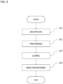
- a laminated film called a precure type As a protective film for a display, a laminated film called a precure type is used. As described in Patent Literature 1, in a precure type laminated film, each layer is already cured at the time of preforming. Thus, in injection molding into a three-dimensional shape or in preforming performed before the injection molding, the laminated film cannot follow a mold having a deep three-dimensional shape, so that the laminated film may be cracked or whitened.
- Curing the laminated film after preforming can increase the crosslinking density of the laminated film as a final product and at the same can make the laminated film follow a mold having a deep three-dimensional shape.
- Such a laminated film is called after-cure type.
- An after-cure type laminated film comprises an uncured hard coat layer and an uncured optical interference layer.
- mix of phases may occur at an interface between the uncured hard coat layer and the uncured optical interference layer due to heat-treatment applied when a decorative layer is formed on the laminated film.
- mix of phases occurs at this interface, the reflectance increases.
- the laminated film is of an after-cure type and has a stretch ratio of 50% or more at 160°C.
- the stretch ratio or the laminated film at 160°C is 50% or more and the thickness of the transparent support substrate is 50 ⁇ m or more and 600 ⁇ m or less, even when formed into a complicated shape, the resulting formed article has sufficient rigidity.
- the preforming makes the laminated film stretch.
- the laminated film to be preformed is in an uncured state.
- the stretch treatment is applied to an uncured laminated film, and no excessive stretch treatment is performed after curing.
- each layer can be formed of a layer-forming composition that will have a high crosslinking density. That is, the hardness of each layer after curing can be further increased.
- both the hard coat layer and the optical interference layer are uncured at the time of lamination, a high degree of adhesion between the layers will be attained. Furthermore, the unevenness of the surface of each layer can be leveled by heat treatment. Accordingly, a laminated film having high smoothness can be obtained.
- the laminated film according to the present embodiment has a transparent support substrate, an uncured hard coat layer formed on at least one surface of the transparent support substrate, and an uncured optical interference layer formed on the uncured hard coat layer.
- the uncured hard coat layer comprises an active energy ray-curable composition for forming a hard coat layer.
- the uncured optical interference layer comprises an active energy ray-curable composition for forming an optical interference layer.
- uncured refers to a state in which the resin is not completely cured.
- the hard coat layer and the optical interference layer contained in the laminated film may be in a semi-cured state.
- the laminated film is of an after-cure type.
- curing is synonymous with "dry through” defined in JIS K 5500 (glossary of terms for coating materials). That is, curing means a) when the center of a test piece is strongly sandwiched between the thumb and the forefinger, no dent due to the fingerprint is formed on the coating surface and no movement of the coating film is noticed, and when the coating surface is rapidly rubbed repeatedly with the fingertip, a dry hard state in which no scratch marks are formed is obtained.
- the laminated film irradiated with an active energy ray having an integral light quantity of 200 mJ/cm 2 can be said to be completely cured.
- semi-cure is synonymous with "dry to touch” defined in JIS K 5500 (glossary of terms for coating materials). That is, the semi-curing refers to when the center of a painted surface is lightly rubbed with a fingertip and the painted surface is in a "dry to touch” state with no rubbing marks.
- the laminated film irradiated with an active energy ray having an integral light quantity of 1 mJ/cm 2 or more and less than 200 mJ/cm 2 can be said to be semi-cured.
- a state in which the hard coat layer and the optical interference layer are not exposed to active energy rays or are exposed to active energy rays of less than 1 mJ/cm 2 can be said as being uncured.
- a laminated film subjected to heating treatment at a temperature of 90°C for 30 minutes has a minimum value R AH of a reflectance taken between wavelengths of 380 nm and 780 nm of 2.0% or less and measured from a side of an uncured optical interference layer.
- the fact that the minimum value R AH of the reflectance is within this range indicates that the occurrence of the mix of phases between the uncured hard coat layer and the uncured optical interference layer is prevented and a clear interface is formed between both the layers.
- the minimum value R AH of the reflectance is preferably 1.8% or less, and more preferably 1.6% or less.
- the minimum value of the reflectance of the laminated film according to the present embodiment may be 2.0% or less even after heating treatment at a temperature of 90°C or more and 120°C or less for 30 minutes or more and 90 minutes or less.
- the laminated film according to the present embodiment has superior antireflection performance.
- a formed article formed by curing the laminated film also has superior antireflection performance.
- the reflection of external light on the formed article is reduced by an antireflection effect.
- the formed article has good display characteristics and good visibility.
- the minimum value R AH of the reflectance is determined by measuring all reflected light including specular reflection in a wavelength region of 380 nm or more and 780 nm or less.
- the minimum value R AH of the reflectance is the smallest value among the reflectances at respective wavelengths measured by a so-called SCI (Specular Component Include) method. Since this method is hardly affected by the surface condition of the object to be measured, the reflectance of the uncured layer can be measured.
- the minimum value R AH of the reflectance of the laminated film can be measured by the following method.
- a black coating material for example, product name: CZ-805 BLACK (manufactured by NIKKO BICS Co., Ltd.) is applied to a surface of the transparent support substrate opposite from the uncured hard coat layer with a bar coater such that a dry film thickness is 3 ⁇ m or more and 6 ⁇ m or less. Thereafter, heating treatment is performed at a temperature of 90°C for 30 minutes to prepare an evaluation sample M.
- CZ-805 BLACK manufactured by NIKKO BICS Co., Ltd.
- the reflectance by the SCI method in a wavelength region of 380 nm or more and 780 nm or less is measured at wavelength intervals of 10 nm using a spectrophotometer (e.g., SD7000 manufactured by Nippon Denshoku Industries Co., Ltd.).
- the reflectance is measured at arbitrary five or more points (preferably, 10 points) of the evaluation sample M.
- a minimum value of the reflectance is determined for each measurement point.
- the minimum value R AH of the reflectance of the laminated film according to the present embodiment does not exceed 2% at all measurement points.
- the minimum value R AH of the reflectance may be measured using an evaluation sample N prepared by irradiating the evaluation sample M with an active energy ray having an integral light quantity of 200 mJ/cm 2 or more. This is because the reflectance hardly changes before and after curing.
- the minimum value R AH of the reflectance and a minimum value R BH of the reflectance of the laminated film before the specific heating treatment measured from the side of the uncured optical interference layer preferably satisfy a relationship: 100 ⁇
- R BH is more preferably 10% or less, and particularly preferably 5% or less.
- the reflectance of the laminated film of the present embodiment is maintained low even when the laminated film is subjected to the specific heating treatment.
- the curing of the composition for forming a hard coat layer and the composition for forming an optical interference layer hardly proceeds through the specific heating treatment.
- the laminated film may be subjected to the specific heating treatment and another heating treatment before being completely cured without affecting the adhesion or the stretch ratio in addition to the reflectance.
- the smoothness of each layer can be improved. Accordingly, the smoothness of the resulting formed article is also improved.
- the conditions for the other heating treatment may be appropriately set according to the composition of each layer.
- the temperature of the other heating treatment may be 90°C or more and 220°C or less, 100°C or more and 220°C or less, or 110°C or more and 220°C or less.
- the time of the other heat treatment may be 10 seconds or more and 10 minutes or less.
- the laminated film is formed into a desired three-dimensional shape by thermoforming.
- the other heating treatment also may be performed by utilizing the heat applied in the preforming step.
- the stretch ratio E 160 of the laminated film at 160°C is 50% or more.
- the laminated film is sufficiently stretched at a forming temperature of 150°C or more and 190°C or less.
- the laminated film can be formed into a complicated three-dimensional shape without generating cracks.
- damage to the laminated film is easily controlled in the preforming step.
- a formed article having functions of a hard coat layer and an optical interference layer and having a complicated three-dimensional shape can be obtained.
- the laminated film is molded into a three-dimensional shape by, for example, preforming and insert molding or the like according to the required physical properties, shape, etc.
- the functions of the hard coat layer and the optical interference layer are, for example, superior hard coat performance and antireflection performance.
- the hard coat performance may be, for example, high hardness, abrasion resistance, and chemical resistance.
- the stretch ratio E 160 of the laminated film is preferably 60% or more, and more preferably 70% or more.
- the stretch ratio E 160 of the laminated film may be less than 400%, less than 350%, or less than 300%.
- the stretch ratio at 160°C of the formed article obtained by curing the laminated film is less than 15%, and may be 5% or less.
- the stretch ratio E 160 can be measured, for example, as follows.
- a tensile tester having a distance between chucks of 150 mm and an evaluation sample cut into a length of 200 mm ⁇ a width of 10 mm are prepared. Under a 160°C atmosphere and under the conditions of a tensile force of 5.0 Kgf and a tensile speed of 300 mm/min, the evaluation sample is stretched by 10% in the long side direction. The presence or absence of cracks in the stretched evaluation sample is visually checked.
- the thickness of the transparent support substrate is 50 ⁇ m or more and 600 ⁇ m or less. Accordingly, even when the laminated film is stretched, the laminated film can maintain rigidity. In addition, warpage of the laminated film and the formed article is easily inhibited. Furthermore, since the transparent support substrate and the laminated film can be wound into a roll form, roll-to-roll processing can be performed.
- the thickness of the transparent support substrate is preferably 100 ⁇ m or more, and more preferably 200 ⁇ m or more.
- the thickness of the transparent support substrate is preferably 500 ⁇ m or less, more preferably 480 ⁇ m or less, even more preferably 450 ⁇ m or less, and particularly preferably 400 ⁇ m or less.
- the thickness of the uncured hard coat layer is not particularly limited.
- the thickness of the uncured hard coat layer is 2 ⁇ m or more and 30 ⁇ m or less.
- the uncured hard coat layer is a dried and uncured hard coat layer (hereinafter, simply referred to as uncured hard coat layer).
- uncured hard coat layer When the uncured hard coat layer has such a thickness, warpage after curing is easily inhibited. In addition, a hard coat layer having superior hard coat performance is obtained.
- the thickness of the uncured hard coat layer is more preferably 3 ⁇ m or more.
- the thickness of the uncured hard coat layer is more preferably 25 ⁇ m or less, and particularly preferably 20 ⁇ m or less.
- the thickness of the uncured optical interference layer is not particularly limited.
- the thickness of the uncured optical interference layer is, for example, 15 nm or more and 200 nm or less.
- the thickness of the uncured optical interference layer is preferably 60 nm or more, and more preferably 65 nm or more.
- the thickness of the uncured optical interference layer is preferably 180 nm or less. When the thickness of the uncured optical interference layer is in this range, good antireflection property can be imparted to the formed article.
- the hardness H BC measured by a nanoindentation method from the optical interference layer side of the laminated film is preferably 0.1 GPa or more from the viewpoint of easily inhibiting damage in the subsequent steps.
- the hardness H BC is 0.1 GPa or more, such defects as depressions or damages to be formed at the time of slit formation and cutting, depressions to be formed due to foreign matters mixed when a plurality of laminated films are laminated, squeegee marks, and suction marks are inhibited, so that the yield is likely to improve.
- the hardness H BC is 0.5 GPa or less is preferable in that adhesion between the uncured hard coat layer and the uncured optical interference layer is easily improved.
- the hardness H BC is 0.5 GPa or less, in laminating the uncured optical interference layer on the uncured hard coat layer, both the layers easily adhere to each other. Furthermore, when the uncured hard coat layer and the uncured optical interference layer are laminated by bonding, entry of air between the layers (air entrapment) is inhibited.
- the hardness H BC is preferably 0.1 GPa or more and 0.5 GPa or less.
- the hardness H BC is more preferably 0.15 GPa or more.
- the hardness H BC is more preferably 0.4 GPa or less.
- the hardness H AC of the laminated film irradiated with an active energy ray having an integral light quantity of 2000 mJ/cm 2 (namely, a cured laminated film (formed article)) measured by a nanoindentation method from the optical interference layer side is preferably 0.25 GPa or more.
- the hardness H AC is preferably 0.7 GPa or less.
- the hardness H AC is preferably 0.25 GPa or more and 0.7 GPa or less.
- the hardness of the laminated film cured after the specific heating treatment also satisfies the above range.
- the hardness H AC is particularly preferably 0.3 GPa or more.
- the hardness H AC may be 0.6 GPa or less.
- the hardness H AC of the formed article is larger than the hardness H BC of the laminated film.
- the hardness H BC satisfies 0.1 GPa or more and 0.5 GPa or less.
- the hardnesses H BC and H AC are calculated based on a value measured by the nanoindentation method from the optical interference layer side of the laminated film or the formed article.
- the hardnesses H BC and H AC are measured under conditions which the surface state of the optical interference layer and the hardness of the transparent support substrate are hardly affected. That is, the hardnesses H BC and H AC are measured by pushing an indenter to the hard coat layer from the optical interference layer side. It can be said that the hardnesses H BC and H AC reflect the hardness of the uncured or cured hard coat layer.
- the hardnesses H BC and H AC are measured at 1000 nm inside the surface of the optical interference layer.
- iMicro Nanoindenter manufactured by NANOMECHANICS, INC.
- NANOMECHANICS, INC. For the continuous stiffness measurement, for example, Advanced Dynamic E and H. NMT method can be used. The load and stiffness can be calculated using iMicro-dedicated software. A load is applied to the sample by the indenter until the load reaches a maximum load of 50 mN.
- the indenter for example, a verkovich type diamond indenter is used.
- the Poisson's ratio of the objects to be measured namely, the uncured hard coat layer and the uncured optical interference layer
- the load, etc. may be appropriately set to appropriate values.
- the hardness H BC is measured by the nanoindentation method and then a mark that agrees with the shape of the indenter used remains on the surface of the optical interference layer, it can be determined that the measured hardness H BC is not accurate.
- the phenomenon described above is considered to occur because the uncured hard coat layer is excessively soft. That is, the hardness measured is strongly affected not by the uncured hard coat layer but by the transparent support substrate.
- the hardness H BC may be regarded as being less than 0.1 GPa.
- the cured laminated film is superior in abrasion resistance. It is preferable that when the surface of the optical interference layer of the laminated film irradiated with an active energy ray having an integral light quantity of 2000 mJ/cm 2 is rubbed 3,000 times while applying a vertical load of 19.6 N per 4 cm 2 , no scratch is visually recognized on the optical interference layer. In this case, decrease in visibility due to change in the appearance of the formed article is easily inhibited.
- the laminated film cured after being subjected to the specific heating treatment also has abrasion resistance satisfying the above condition.
- No scratch is visually recognized means that no scratch can be visually observed.
- the “scratch” is, for example, roughness of the surface. As long as no scratches are visually observed, very slight scratches may be observed when the sample after an abrasion test is observed using a microscope at a magnification of 100 times.
- the abrasion test is performed using a known method under the above conditions.
- a friction block to which a cotton cloth is fixed is usually used. This friction block applies a vertical load (specifically, 19.6 N per 4 cm 2 ) to the sample.
- the laminated film may be subjected to the specific heating treatment before irradiation with an active energy ray.
- the laminated film may be subjected to heating treatment in an atmosphere at 150 to 190°C for 30 to 60 seconds in addition to or instead of the specific heating treatment. Thanks to these heating treatments, the surface of the laminated film is smoothened by leveling, so that the abrasion resistance is easily further improved.
- the coefficient of static friction ⁇ AC of the optical interference layer of the laminated film irradiated with an active energy ray having an integral light quantity of 2000 mJ/cm 2 is preferably 0.3 or less, more preferably 0.25 or less, and particularly preferably 0.20 or less.
- the coefficient of static friction is measured in accordance with JIS K 7125.
- the coefficient of static friction of the laminated film cured after the specific heating treatment also satisfies the above range.
- the optical interference layer is laminated in an uncured state with the uncured hard coat layer. Furthermore, the laminated film is subjected to various processing in an uncured state.
- the optical interference layer is required to have high hardness in addition to antireflection performance, to have low tack and be less likely to be polluted, to be inhibited from damage and change in appearance during processing, to be inhibited from curling due to the difference in thermal shrinkage from other layers, etc.
- the optical interference layer is required to have superior antireflection performance, low tack and resistance to pollution, and to be inhibited from damage during processing (for example, depressions such as suction marks and squeegee marks in the decoration step).
- the hard coat layer is also laminated in an uncured state with the uncured optical interference layer. Furthermore, as described above, the laminated film is subjected to various processing in an uncured state. Thus, similar to the optical interference layer, the uncured hard coat layer is required to have high hardness, to have low tack and be less likely to be polluted, to inhibit damage and change in appearance (for example, foaming or cracking in the preforming step) during processing, and to inhibit curling due to a difference in thermal shrinkage from other layers, etc.
- the physical properties of the uncured hard coat layer can be adjusted by the thickness thereof, the composition of the composition for forming the hard coat layer, etc.
- the transparent support substrate is not particularly limited as long as it is transparent.
- To be transparent specifically means that the total light transmittance is 80% or more.
- the total light transmittance of the transparent support substrate is 80% or more, and preferably 90% or more.
- the total light transmittance can be measured by a method in accordance with JIS K 7361-1.
- As the transparent support substrate those known in the art are used without particular limitation.
- the transparent support substrate may be either colorless or colored.
- the transparent support substrate is appropriately selected according to the application.
- the transparent support substrate include polyester films such as polycarbonate (PC), polyethylene terephthalate and polyethylene naphthalate; cellulose films such as diacetylcellulose and triacetylcellulose; acrylic films such as polymethyl methacrylate (PMMA); styrene films such as polystyrene and acrylonitrilestyrene copolymers; olefin films such as polyvinyl chloride, polyethylene, polypropylene, polyolefin having a cyclic or norbornene structure, and ethylenepropylene copolymers; and amide films such as nylon and aromatic polyamide.
- polyester films such as polycarbonate (PC), polyethylene terephthalate and polyethylene naphthalate
- cellulose films such as diacetylcellulose and triacetylcellulose
- acrylic films such as polymethyl methacrylate (PMMA)
- styrene films such as polystyrene and
- the transparent support substrate may be a film comprising a resin such as polyimide, polysulfone, polyether sulfone, polyether ether ketone, polyphenylene sulfide, polyvinyl alcohol, polyvinylidene chloride, polyvinyl butyral, polyallylate, polyoxymethylene, and epoxy resin, or may be a film comprising a blend of those polymers.
- a resin such as polyimide, polysulfone, polyether sulfone, polyether ether ketone, polyphenylene sulfide, polyvinyl alcohol, polyvinylidene chloride, polyvinyl butyral, polyallylate, polyoxymethylene, and epoxy resin, or may be a film comprising a blend of those polymers.
- the transparent support substrate may be a laminate of a plurality of films.
- the transparent support substrate may be a laminate made up of a film made of an acrylic resin and a film made of a polycarbonate resin.
- the transparent support substrate may have either optical anisotropy or isotropy.
- the magnitude of birefringence of the transparent support substrate having optical anisotropy is not particularly limited.
- the phase difference of the transparent support substrate having anisotropy may be 1/4 of the wavelength ( ⁇ /4) or may be 1/2 of the wavelength ( ⁇ /2).
- the uncured optical interference layer comprises an active energy ray-curable composition for forming an optical interference layer, which hereinafter may be referred to as composition R.
- the composition R is cured by active energy rays. By adjusting the integral light quantity of the active energy ray, the hardness and/or the stretch ratio of the optical interference layer can be controlled.
- the active energy ray is an ionizing radiation such as an ultraviolet ray, an electron beam, an ⁇ ray, a ⁇ ray, or a ⁇ ray.
- the composition R is preferably of an ultraviolet-curable type.
- the optical interference layer functions as a layer having a low refractive index.
- the refractive index of the cured optical interference layer is, for example, 1.20 or more and 1.55 or less, and may be 1.25 or more and 1.50 or less, and may be 1.30 or more and 1.45 or less. Accordingly, good antireflection property is exhibited.
- composition R comprises, for example, a first layer-forming component and low-refractive particles.
- the low-refractive particles are particles having a low refractive index, and reduce the refractive index of the optical interference layer.
- the content of the low-refractive particles is preferably 20 parts by mass or more, more preferably 30 parts by mass or more, and particularly preferably 40 parts by mass or more based on 100 parts by mass of the solid content of the composition R. Accordingly, the optical interference layer is likely to exhibit superior antireflection property.
- the content of the low-refractive particles is preferably 80 parts by mass or less, more preferably 75 parts by mass or less, and particularly preferably 70 parts by mass or less based on 100 parts by mass of the solid content of the composition R.
- the first layer-forming component comprises a first reactive component having two or more polymerizable functional groups in one molecule.
- the first reactive component comprises at least one selected from the group consisting of a first monomer, a first oligomer, and a first polymer.
- the weight-average molecular weights of the first monomer and the first oligomer are 10,000 or less, and may be 9000 or less.
- the weight-average molecular weight of the first polymer is more than 10,000, and may be 20,000 or more.
- the weight-average molecular weight of the first polymer may be 100,000 or less.
- the weight-average molecular weight (Mw) can be calculated based on the molecular weight of standard polystyrene from a chromatogram measured by gel permeation chromatography.
- the first reactive component preferably comprises a (meth)acrylate compound.
- the (meth)acrylate compound include acrylic (meth)acrylate compounds such as an acrylic (meth)acrylate monomer, an acrylic (meth)acrylate oligomer, and an acrylic (meth)acrylate polymer; urethane (meth)acrylate compounds such as a urethane (meth)acrylate monomer, a urethane (meth)acrylate oligomer, and a urethane (meth)acrylate polymer; and silicon (meth)acrylate compounds such as a silicon (meth)acrylate, a silicon (meth)acrylate oligomer, and a silicon (meth)acrylate polymer. These are used singly or two or more of them are used in combination.
- “(Meth)acrylate” means acrylate and/or methacrylate.
- the acryl equivalents of the first monomer and the first oligomer are not particularly limited. From the viewpoint of reactivity, the acryl equivalents of the first monomer and the first oligomer are preferably 100 g/eq. or more, more preferably 110 g/eq. or more, and particularly preferably 115 g/eq. or more. The acryl equivalents of the first monomer and the first oligomer may be 200 g/eq. or less, 180 g/eq. or less, or 160 g/eq. or less.
- Examples of the (meth)acrylate monomer, which is a starting material of the (meth)acrylate polymer include methyl (meth)acrylate, ethyl (meth)acrylate, n-butyl (meth)acrylate, isobutyl (meth)acrylate, 2-ethylhexyl (meth)acrylate, acrylic acid, methacrylic acid, isostearyl (meth)acrylate, ethoxylated o-phenylphenol acrylate, methoxypolyethylene glycol acrylate, methoxypolyethylene glycol acrylate, phenoxypolyethylene glycol acrylate, 2-acryloyloxyethyl succinate, 2-hydroxyethyl (meth)acrylate, 2-hydroxypropyl (meth)acrylate, ethylene glycol mono(meth)acrylate, propylene glycol mono(meth)acrylate, 2-hydroxy-3-methoxypropyl (meth)acrylate, dipentaerythritol
- acrylic (meth)acrylate oligomer or polymer examples include a polymer of at least one of the (meth)acrylate monomers described above.
- urethane (meth)acrylate polymer examples include a polymer of at least one of the above-mentioned urethane (meth)acrylate monomers and oligomers.
- the silicon (meth)acrylate compound is a (meth)acrylate compound having a siloxane linkage. Although it should not be construed as being limited to a particular theory, the silicon (meth)acrylate compound makes it possible to reduce the surface tension of the uncured optical interference layer, improve the leveling property, and reduce the tackiness.
- the first reactive component (typically, a (meth)acrylate compound) may contain a fluorine atom.
- the first layer-forming component may comprise a non-reactive component having less than two polymerizable functional groups in one molecule.
- the mix of phases is considered to occur mainly as a result of thermally caused diffusion of a monomer and/or an oligomer having a small molecular weight contained in the hard coat layer and reaching of the monomer and/or the oligomer to the optical interference layer.
- the low-refractive particles can inhibit the thermally caused diffusion of the monomer and/or the oligomer from the hard coat layer to the optical interference layer.
- the first polymer has a small effect of inhibiting the thermally caused diffusion of the monomer and/or the oligomer from the hard coat layer to the optical interference layer.
- the composition R preferably contains the first polymer such that the content X of the low-refractive particles and the content Z of the first polymer satisfy the following relationship: 100 ⁇ Z/(X + Z) ⁇ 40 (%). It is more preferable to satisfy the relationship of 100 ⁇ Z/(X + Z) ⁇ 35 (%), and particularly preferable to satisfy the relationship of 100 ⁇ Z/(X + Z) ⁇ 30 (%).
- the composition R may comprise inorganic oxide fine particles.
- the inorganic oxide fine particles inhibit volume shrinkage of the uncured optical interference layer and easily increase rigidity. Thus, change in appearance during the process of producing the uncured optical interference layer is easily inhibited. Furthermore, change in appearance of the cured optical interference layer and occurrence of curling are also prevented. In addition, the tackiness of the cured optical interference layer is reduced and the abrasion resistance is easily improved.
- the content of the inorganic oxide fine particles is preferably 1 part by mass or more, more preferably 5 parts by mass or more, and particularly preferably 7 parts by mass or more based on 100 parts by mass of the solid content of the composition R.
- the content of the inorganic oxide fine particles is preferably 20 parts by mass or less, more preferably 18 parts by mass or less, and particularly preferably 15 parts by mass or less based on 100 parts by mass of the solid content of the composition R.
- the solid content of the composition R is the total components of the composition R excluding the solvent. The same applies to the solid content of the composition for forming a hard coat layer.
- the inorganic oxide fine particles are not particularly limited.
- examples of the inorganic oxide fine particles include silica (SiO 2 ) particles (excluding hollow particles), alumina particles, titania particles, tin oxide particles, antimony-doped tin oxide (ATO) particles, and zinc oxide particles.
- the surface of the inorganic oxide fine particles may be modified with a functional group containing an unsaturated double bond.
- the functional group is desirably a (meth)acryloyl group.
- silica particles and alumina particles are preferable from the viewpoint of cost and coating material stability, and in particular, silica particles and alumina particles whose surfaces are modified with a functional group are preferable.
- the form of the inorganic oxide fine particles may be sol.
- the average particle size of the inorganic oxide fine particles is not particularly limited. From the viewpoint of transparency and coating material stability, the average particle size of the inorganic oxide fine particles is preferably 5 nm or more and 100 nm or less.
- the average particle size of the inorganic oxide fine particles is a value measured using image processing software from an image of a cross section taken with an electron microscope. The average particle size of other granular materials is also determined by the same method.
- the composition R preferably comprises a photoinitiator. Accordingly, polymerization of the active energy ray-curable resin component easily proceeds.
- photoinitiator examples include alkylphenone-based photoinitiators, acylphosphine oxide-based photoinitiators, titanocene-based photoinitiators, and oxime ester-based polymerization initiators.
- alkylphenone-based photoinitiator examples include 2,2-dimethoxy-1,2-diphenylethan-1-one, 1-hydroxy-cyclohexyl-phenyl-ketone, 2-hydroxy-2-methyl-1-phenyl-propan-1-one, 1-[4-(2-hydroxyethoxy)-phenyl]-2-hydroxy-2-methyl-1-propan-1-one, 2-hydroxy-1-14-[4-(2-hydroxy-2-methyl-propionyl)-benzyl]phenyl ⁇ -2-methyl-propan-1-one, 2-methyl-1-(4-methylthiophenyl)-2-morpholinopropan-1 -one, 2-benzyl-2-dimethylamino-1-(4-morpholinophenyl)butanone-1, and 2-(dimethylamino)-2-[(4-methylphenyl)methyl]-1-[4-(4-morpholinyl)phenyl]-1-butanone.
- acylphosphine oxide-based photoinitiators examples include 2,4,6-trimethylbenzoyl-diphenyl-phosphine oxide and bis(2,4,6-trimethylbenzoyl)-phenylphosphine oxide.
- titanocene-based photoinitiators examples include bis( ⁇ 5-2,4-cyclopentadien-1-yl)-bis(2,6-difluoro-3-(1H-pyrrol-1-yl)-phenyl)titanium.
- oxime ester-based polymerization initiator examples include 1,2-octanedione, 1- [4-(phenylthio)-, 2-(O-benzoyloxime)], ethanone, 1-[9-ethyl-6-(2-methylbenzoyl)-9H-carbazol-3-yl]-, 1-(O-acetyloxime), oxyphenylacetic acid, 2-[2-oxo-2-phenylacetoxyethoxy]ethyl ester, and 2-(2-hydroxyethoxy)ethyl ester.
- photoinitiators are used singly or two or more of them are used in combination.
- the content of the photoinitiator is preferably 0.01 parts by mass or more, more preferably 1 part by mass or more, and particularly preferably 3 parts by mass or more based on 100 parts by mass of the solid content of the composition R.
- the content of the photoinitiator is preferably 10 parts by mass or less, more preferably 7 parts by mass or less, and particularly preferably 5 parts by mass or less based on 100 parts by mass of the solid content of the composition R.
- the composition R may contain a solvent.
- the solvent is not particularly limited, and is appropriately selected in consideration of the components contained in the composition, the type of the transparent support substrate, the application method, etc.
- the solvent examples include aromatic solvents such as toluene and xylene; ketone solvents such as methyl ethyl ketone, acetone, methyl isobutyl ketone, and cyclohexanone; ether solvents such as diethyl ether, isopropyl ether, tetrahydrofuran, dioxane, ethylene glycol dimethyl ether, ethylene glycol diethyl ether, diethylene glycol dimethyl ether, diethylene glycol diethyl ether, propylene glycol monomethyl ether, anisole, and phenetole; ester solvents such as ethyl acetate, butyl acetate, isopropyl acetate, and ethylene glycol diacetate; amide solvents such as dimethylformamide, diethylformamide, and N-methylpyrrolidone; cellosolve solvents such as methyl cellosolve, ethyl cellosolve, and buty
- the composition R may comprise various additives, as necessary.
- the additives include antistatic agents, plasticizers, surfactants, antioxidants, ultraviolet absorbers, surface conditioning agents, surface modifiers, leveling agents, and light stabilizers (e.g., hindered amine light stabilizer (HALS)).
- HALS hindered amine light stabilizer
- the content of each additive is preferably 1 part by mass or more, more preferably 3 parts by mass or more, and particularly preferably 5 parts by mass or more based on 100 parts by mass of the solid content of the composition R.
- the content of each additive is preferably 20 parts by mass or less, and more preferably 15 parts by mass or less based on 100 parts by mass of the solid content of the composition R.
- the uncured hard coat layer contains an active energy ray-curable composition for forming a hard coat layer, which hereinafter may be referred to as composition HC.
- composition HC is cured by active energy rays. By adjusting the integral light quantity of the active energy ray, the hardness and/or the stretch ratio of the hard coat layer can be controlled.
- the composition HC is preferably cured by the same type of active energy ray as the composition R.
- composition HC comprises a second layer-forming component.
- the total content of the second oligomer and the second monomer is preferably 25 parts by mass or more and 65 parts by mass or less based on 100 parts by mass of the solid content of the composition HC.
- the hardness H BC is easily controlled to 0.5 GPa or less.
- the total content of the second oligomer and the second monomer is preferably 28 parts by mass or more, and more preferably 30 parts by mass or more based on 100 parts by mass of the solid content of the composition HC.
- the hardness H BC is easily controlled to 0.1 GPa or more.
- the total content of the second oligomer and the second monomer is preferably 62 parts by mass or less, and more preferably 60 parts by mass or less based on 100 parts by mass of the solid content of the composition HC.
- the second reactive component preferably comprises a second polymer having a weight-average molecular weight of more than 10,000 together with the second monomer and/or the second oligomer.
- the weight-average molecular weight of the second polymer is more than 10,000, and may be 20,000 or more.
- the weight-average molecular weight of the second polymer may be 100,000 or less.
- Examples of a preferable second reactive component include the same (meth)acrylate compounds as those recited as examples as the first reactive component. From the viewpoint of adhesion to the transparent support substrate and the optical interference layer and transparency, the second reactive component preferably comprises a (meth)acrylate compound.
- the composition HC may comprise inorganic oxide fine particles.
- the inorganic oxide fine particles include those recited as examples for the composition R.
- the content of the inorganic oxide fine particles is preferably 20 parts by mass or less, more preferably 18 parts by mass or less, and particularly preferably 15 parts by mass or less based on 100 parts by mass of the solid content of the composition HC.
- the content of the inorganic oxide fine particles is preferably 0.1 parts by mass or more, more preferably 1 part by mass or more, and particularly preferably 3 parts by mass or more based on 100 parts by mass of the solid content of the composition HC.
- the composition HC preferably comprises a photoinitiator. Accordingly, polymerization of the active energy ray-curable resin component easily proceeds.
- the photoinitiator include those recited as examples for the composition R.
- the amount of the photoinitiator is preferably 0.01 parts by mass or more and 10 parts by mass or less, and more preferably 1 part by mass or more and 10 parts by mass or less, per 100 parts by mass of the solid content of the composition HC.
- the composition HC may comprise a solvent.
- the solvent is not particularly limited, and is appropriately selected in consideration of the components contained in the composition, the type of the transparent support substrate, the application method, etc.
- Examples of the solvent include those recited as examples for the composition R. Among them, ester solvents, ether solvents, alcohol solvents, and ketone solvents are preferable.
- composition HC may comprise various additives, as necessary.
- additives include those recited as examples for the composition R.
- the resin components of the composition HC and the composition R may be the same or different. Among them, both resin components are preferably the same or the same type. This is because adhesion between the uncured hard coat layer and the uncured optical interference layer is improved, and delamination between the layers hardly occurs.
- the laminated film may further have at least one uncured functional layer between the uncured hard coat layer and the uncured optical interference layer.
- the functional layer reinforces the optical function of the laminated film or imparts a new optical function.
- a preferable functional layer is, for example, at least one of an optical interference layer having a high refractive index and an optical interference layer having a medium refractive index.
- the refractive index of the high refractive index layer may be, for example, more than 1.55 and 2.00 or less.
- the refractive index of the medium refractive index layer is not particularly limited as long as it is between the optical interference layer (the low refractive index layer) and the high refractive index layer.
- the refractive index of the medium refractive index layer may be, for example, 1.55 or more and 1.75 or less.
- composition for forming a functional layer that forms the functional layer may comprise the same components as those contained in the composition HC or the composition R described above.
- the composition for forming a functional layer that forms the other optical interference layer may comprise the same components as those contained in the composition R.
- the composition for forming a functional layer that forms the other optical interference layer may comprise high-refractive particles.
- the components contained in the plurality of functional layers may be either the same or different.
- the laminated film may have a protective film on a surface of the uncured optical interference layer on a side opposite from the uncured hard coat layer. Accordingly, damage is easily inhibited when the laminated film is wound into a roll or unwound from a roll.
- the protective film is made of, for example, resin.
- the resin film include polyolefin films such as polyethylene films and polypropylene films (including an unoriented polypropylene film (CPP film) and a biaxially oriented polypropylene film (OPP film)), modified polyolefin films obtained by modifying these polyolefins to add further functions, polyester films such as polyethylene terephthalate, polycarbonate and polylactic acid, polystyrene resin films such as polystyrene films, AS resin films and ABS resin films, nylon films, polyamide films, polyvinyl chloride films and polyvinylidene chloride films, and polymethylpentene films.
- polyolefin films such as polyethylene films and polypropylene films (including an unoriented polypropylene film (CPP film) and a biaxially oriented polypropylene film (OPP film)
- modified polyolefin films obtained by modifying these polyolefins to add further functions
- polyester films such as poly
- Additives such as an antistatic agent and an ultraviolet inhibitor may be added to the resin film, as necessary.
- the surface of the resin film may have been subjected to corona treatment or low-temperature plasma treatment.
- At least one selected from among a polyethylene film, a polystyrene film, a modified polyolefin film, a polymethylpentene film, an OPP film, and a CPP film each having a thickness of not less than 30 ⁇ m and not more than 100 ⁇ m is preferable.
- the formed article is particularly suitable as a protective material for a display and various sensors disposed around the display.
- the display include a liquid crystal display, an organic EL display, and a plasma display.
- the formed article is particularly suitable as a protective material for a touch panel display for vehicles and devices disposed around the display.
- the formed article is disposed such that the optical interference layer is outside the hard coat layer.
- the formed article includes, for example, a transparent support substrate, a hard coat layer and an optical interference layer disposed on one main surface of the transparent support substrate, and a decorative layer disposed on the other main surface of the transparent support substrate.
- the decorative layer may be provided on a part of the other main surface of the transparent support substrate.
- the decorative layer is a layer that provides decoration, such as a pattern, characters, or metallic luster, to the formed article. By the decorative layer, the designability of the formed article is enhanced.
- the decorative layer examples include at least one of a print layer and a vapor-deposited layer.
- Each of the print layer and the vapor-deposited layer has one or more layers, and may comprise a plurality of layers.
- the thickness of the decorative layer is not particularly limited, and is appropriately set according to designability, etc.
- the print layer for example, a wood grain pattern, a stone grain pattern, a cloth grain pattern, a sand grain pattern, a geometric pattern, characters, or a solid print is drawn.
- the print layer is formed of, for example, a coloring ink comprising a binder resin and a colorant.
- the binder resin is not particularly limited.
- the colorant is not particularly limited, and examples thereof include known pigments and dyes.
- Examples of a yellow pigment include azo-based pigments such as polyazo pigments, organic pigments such as isoindolinone, and inorganic pigments such as titanium nickel antimony oxide.
- Examples of a red pigment include azo-based pigments such as polyazo pigments, organic pigments such as quinacridone, and inorganic pigments such as rouge.
- Examples of a blue pigment include organic pigments such as phthalocyanine blue and inorganic pigments such as cobalt blue.
- Examples of a black pigment include organic pigments such as aniline black.
- Examples of a white pigment include inorganic pigments such as titanium dioxide.
- the vapor-deposited layer is formed of at least one metal selected from the group comprising aluminum, nickel, gold, platinum, chromium, iron, copper, indium, tin, silver, titanium, lead and zinc or an alloy or compound thereof.
- the formed article may comprise a transparent support substrate, a hard coat layer and an optical interference layer disposed on one main surface of the transparent support substrate, a decorative layer disposed on the other main surface of the transparent support substrate, and a formed resin layer.
- the decorative layer is disposed so as to be sandwiched between the transparent support substrate and the formed resin layer.
- the resin that forms the formed resin layer is not particularly limited.
- the formed resin layer comprises, for example, a thermosetting resin and/or a thermoplastic resin.
- the thermosetting resin include phenol resin, epoxy resin, melamine resin, urea resin, unsaturated polyester, and thermosetting polyimide.
- the thermoplastic resin include so-called engineering plastics. Examples of the engineering plastics include polyamide, polyacetal, polycarbonate, ultra-high molecular weight polyethylene, polysulfone, polyether sulfone, polyphenylene sulfide, and liquid crystal polymer.
- FIG. 2 is a cross-sectional view schematically showing a formed article according to the present embodiment.
- the formed article 20 includes a transparent support substrate 11, a cured hard coat layer 22 disposed on one main surface thereof, a cured optical interference layer 23 formed on the hard coat layer 22, a decorative layer 24, and a formed resin layer 25.
- the decorative layer 24 is disposed to cover a part of the other main surface of the transparent support substrate 11.
- the formed resin layer 25 is disposed so as to cover the whole of the other main surface of the transparent support substrate 11 and the whole of the decorative layer 24.
- the stretch ratio of the resulting laminated film at 160°C is 50% or more, and the minimum value R AH of the reflectance after the specific heating treatment is 2% or less.
- FIG. 3 is a flowchart showing the method for manufacturing a laminated film according to the present embodiment.
- the method for forming the uncured hard coat layer is not particularly limited.
- the uncured hard coat layer is formed by, for example, applying the composition HC to one surface of the transparent support substrate.
- the composition HC can be prepared by a method commonly practiced by those skilled in the art. For example, it can be prepared by mixing the above-described components by using a commonly used mixing device such as a paint shaker and a mixer.
- the method of the application of the composition HC is not particularly limited, and the application is performed by a method usually performed by those skilled in the art.
- Examples of the application method include a dip coating method, an air knife coating method, a curtain coating method, a roller coating method, a bar coating method (for example, a wire bar coating method), a die coating method, an inkjet method, and a gravure coating method.
- the amount of the composition HC applied is not particularly limited.
- the composition HC is applied such that, for example, the thickness of the uncured hard coat layer after drying is 2 ⁇ m or more and 30 ⁇ m or less.
- a drying step may be performed.
- the drying conditions are not particularly limited, and are appropriately set such that at least part of the solvent contained in the composition HC is removed.
- Examples of the drying method include air drying (natural drying), heat drying, and vacuum drying. Among them, heat drying is preferable.
- heat drying is preferable.
- the drying is performed after the uncured hard coat layer is formed on the transparent support substrate and before the uncured hard coat layer is subjected to the lamination step. For example, the uncured hard coat layer is dried before the transparent support substrate provided with the uncured hard coat layer is carried into a lamination machine.
- the method for forming the uncured optical interference layer is not particularly limited.
- the uncured optical interference layer is formed by, for example, applying the composition R onto one surface of another support substrate (typically, the protective film described above).
- the method for applying the composition R is performed by a technique that is usually performed by those skilled in the art, similarly to the composition HC.
- the amount of the composition R applied is not particularly limited.
- the composition R is applied such that, for example, the thickness of the uncured optical interference layer after drying is 15 nm or more and 200 nm or less.
- a drying step may be performed.
- the drying conditions are not particularly limited, and are appropriately set such that at least part of the solvent contained in the composition R is removed.
- Examples of the drying method include the same methods for the drying of the hard coat layer. Among them, heat drying is preferable. By heating, the uncured optical interference layer can be leveled along with being dried.
- the drying is performed after the uncured optical interference layer is formed on the other support substrate and before the uncured optical interference layer is subjected to the lamination step.
- the uncured optical interference layer is dried before the other support substrate provided with the uncured optical interference layer is carried into a lamination machine.
- the other support substrate may be wound into a roll form. Accordingly, roll-to-roll processing can be performed until the lamination step. Moreover, after a protective film is bonded to the surface of the uncured optical interference layer, the other support substrate may be wound. The protective film and the uncured optical interference layer may be bonded to each other with an adhesive layer interposed therebetween.
- the uncured optical interference layer formed on the other support substrate and the uncured hard coat layer formed on the transparent support substrate are bonded. Accordingly, a laminated film is obtained. After both layers are bonded, the other support substrate may be peeled off.
- the transparent support substrate provided with the uncured hard coat layer is carried into a laminating machine, and the other support substrate wound is carried into the laminating machine while being unwound.
- the other support substrate provided with the uncured optical interference layer is carried into a laminating machine, and the transparent support substrate wound is carried into the laminating machine while being unwound.
- the bonding is preferably performed while applying pressure.
- the pressure may be, for example, 0.1 N/cm or more and 50 N/cm or less.
- the pressure is preferably 0.5 N/cm or more.
- the pressure is preferably 30 N/cm or less.
- each layer at the time of bonding is not particularly limited. Since all the layers are uncured, the layers can be bonded at a low temperature. On the other hand, since the laminated film according to the present embodiment is likely to be inhibited from the occurrence of mix of phases, each layer may be heated at the time of bonding. The temperature of each layer at the time of bonding may be 0°C or more and 100°C or less.
- a laminated film having an uncured functional layer between an uncured hard coat layer and an uncured optical interference layer is manufactured, for example, through the following steps.
- another uncured functional layer is formed on a new support substrate. Subsequently, a surface of the uncured hard coat layer opposite from the transparent support substrate and a surface of the uncured functional layer opposite from the new support substrate are bonded to each other. The new support substrate is peeled off, and then the uncured optical interference layer supported by the other support substrate is bonded to the exposed uncured functional layer. If necessary, before bonding the optical interference layer, a step of bonding the uncured functional layer to the uncured hard coat layer or the uncured functional layer laminated thereon is repeated.
- a laminated film including a transparent support substrate, an uncured hard coat layer, at least one uncured functional layer, an optical interference layer, and another support substrate in this order is obtained.
- the other support substrates may or may not be peeled off.
- the laminated film may be wound into a roll. In this case, it is preferable that the other support substrate has not been peeled off.
- FIG. 4 is a schematic diagram for explaining a lamination step in a method for manufacturing a laminated film according to the present embodiment.
- An uncured hard coat layer 12 is formed on one surface of a transparent support substrate 11. This laminate is obtained in a step of forming the uncured hard coat layer. This laminate is conveyed in a flat state from the left side toward the right side in FIG. 4 .
- an uncured optical interference layer 13 is laminated on one surface of another support substrate 14. This laminate is obtained in the step of forming an uncured optical interference layer. This laminate is conveyed in a flat state from the left side toward the right side in FIG. 4 .
- a surface of the uncured hard coat layer 12 opposite from the transparent support substrate 11 and a surface of the uncured optical interference layer 13 opposite from the other support substrate 14 are bonded to each other by application of pressure with a pair of rollers 30. Accordingly, a laminated film including the transparent support substrate 11, the uncured hard coat layer 12, the optical interference layer 13, and the other support substrate 14 in this order is obtained.
- each layer and each substrate, the position, size, and the like of the rollers may be appropriately set.
- the formed article according to the present embodiment is manufactured, for example, by a method comprising: a decoration step of forming a decorative layer on the other main surface of the transparent support substrate of the laminated film; and a curing step of irradiating the laminated film with an active energy ray having an integral light quantity of 200 mJ/cm 2 or more after the decoration step.
- the decoration step includes a heating step of heating the laminated film at 80°C or more for 20 minutes or more.
- an injection molding step, or a preforming step and an injection molding step are performed, as necessary.
- the laminated film is formed into a shape conforming with a desired three-dimensional shape by thermoforming.
- the curing step may be performed multiple times. For example, after the preforming step, a semi-curing step of irradiating part of the laminated film with an active energy ray may be performed. In this case, after the injection molding step, a main curing step of irradiating the laminated film with an active energy ray so as to cure the remaining part is performed.
- the formed article is manufactured, for example, by a method comprising a decoration step (S21), a preforming step (S22), a curing step (S23), and an injection molding step (S24) in this order.
- FIG. 5 is a flowchart showing a method of manufacturing a formed article according to the present embodiment.
- the formed article is manufactured by a method including, for example, a decoration step (S21), a preforming step (S22), a semi-curing step (S23-1), an injection molding step (S24), and a main curing step (S23-2) in this order.
- FIG. 6 is a flowchart showing a method of manufacturing another formed article according to the present embodiment.
- a step of unwinding the laminated film from the roll to form a slit or cut the laminated film into a desired shape and size may be performed before the decoration step.
- a decorative layer (typically, a print layer and a vapor-deposited layer) is formed on the other main surface of the transparent support substrate of the laminated film.
- the method for forming the print layer is not particularly limited. Examples of the method for forming the print layer include an offset printing method, a gravure printing method, a screen printing method, a roll coating method, and a spray coating method.
- the method for forming the vapor-deposited layer is also not particularly limited. Examples of the method for forming the vapor-deposited layer include a vacuum vapor deposition method, a sputtering method, an ion plating method, and a plating method.
- the decoration step includes a heating step of heating the laminated film at 80°C or more for 20 minutes or more.
- the heating step is performed, for example, for drying the decorative layer.
- the resulting formed article has a low reflectance.
- the decoration step may be performed a plurality of times while changing the color, for example.
- heating at a temperature higher than 80°C for 5 minutes or less, or heating at a temperature lower than 80°C for 20 minutes or more may be further performed. Such heating does not significantly participate in the occurrence of mix of phases.
- the laminated film is preformed into a shape conforming to a desired three-dimensional shape.
- injection molding typically, insert-mold lamination (IML) molding.
- IML molding the laminated film is inserted into a mold, and a resin for molding is injected toward the laminated film.
- a trimming step of removing unnecessary parts of the laminated film may be performed.
- the method of preforming is not particularly limited.
- the preforming is performed by, for example, a vacuum molding method, an air-pressure molding method, or a vacuum pressure molding method.
- the mold and the laminated film are placed in the same processing chamber.
- the laminated film is placed such that the transparent support substrate faces the mold.
- the laminated film is heated and the processing chamber is brought into a vacuum state and/or a pressurized state. Accordingly, the laminated film is deformed along the mold.
- the laminated film is cooled and then removed from the mold.
- the laminated film may be heated at 90°C or more and 190°C or less for 20 seconds or more and 5 minutes or less.
- An active energy ray is irradiated so that a part of the laminated film is cured. Accordingly a laminated film in a semi-cured state is obtained.
- the integral light quantity of the active energy ray is, for example, 1 mJ/cm 2 or more and less than 200 mJ/cm 2 .
- the type of the active energy ray is not particularly limited.
- the active energy ray is appropriately selected according to the type of the resin component contained in the layer-forming composition.
- the active energy ray is not particularly limited, and may be an ionizing radiation such as ultraviolet ray, electron beam, ⁇ ray, ⁇ ray, and ⁇ ray. Among them, ultraviolet rays having a wavelength of 380 nm or less are preferable. Ultraviolet ray is irradiated using, for example, a high-pressure mercury lamp or an ultra-high-pressure mercury lamp.
- the optical interference layer is made to face a mold and a resin for molding is injected against the transparent support substrate. Accordingly the laminated film is formed into the shape of the mold, and a formed resin layer is formed on the other main surface of the transparent support substrate.
- the laminated film is irradiated with an active energy ray and the laminated film is thereby completely cured. Accordingly, a formed article is obtained.
- the integral light quantity of the active energy ray in the main curing step is 200 mJ/cm 2 or more.
- the integral light quantity of the active energy ray may be 5000 mJ/cm 2 or less, and may be 3000 mJ/cm 2 or less.
- the active energy ray may be of the same type as or different from that of the semi-curing step.
- the acrylic polymers A, B and C were prepared as follows.
- a mixture of 30.0 parts of 2,3-epoxypropyl methacrylate, 70 parts of methyl methacrylate, and 1.5 parts of t-butyl peroxy-2-ethylhexanoate was prepared.
- 40.0 parts of toluene was added to a 500 ml reaction vessel equipped with a stirring blade, a nitrogen introduction tube, a cooling tube, and a dropping funnel, and heated to 110°C. While the inside of the reaction vessel was stirred, the mixture was added dropwise at a constant speed over 2 hours under a nitrogen atmosphere. After the completion of the dropwise addition, a reaction was performed for 1 hour under a temperature condition of 110°C.
- a reaction vessel of the same type as above was charged with 226.5 parts of the precursor A1, 15.66 parts of acrylic acid, 0.43 parts of hydroquinone monomethyl ether, and 56 parts of toluene, which were then heated to 90°C with blowing air and stirring. Under a temperature condition of 90°C, a mixed solution of 3.0 parts of toluene and 0.81 parts of tetrabutylammonium bromide was added to the reaction vessel and reacted for 1 hour. Subsequently, the reaction liquid was heated to 105°C, and it was reacted under a temperature condition of 105°C until the acid value of the solid in the reaction liquid became 8 or less.
- the acid value was measured in accordance with JIS K 5601-2-1 as follows.
- a mixture of 30.0 parts of 2,3-epoxypropyl methacrylate, 70 parts of methyl methacrylate, and 10.0 parts of t-butyl peroxy-2-ethylhexanoate was prepared.
- 40.0 parts of toluene was added to a 500 ml reaction vessel equipped with a stirring blade, a nitrogen introduction tube, a cooling tube, and a dropping funnel, and heated to 110°C. While the inside of the reaction vessel was stirred, the mixture was added dropwise at a constant speed over 2 hours under a nitrogen atmosphere. After the completion of the dropwise addition, a reaction was performed for 1 hour under a temperature condition of 110°C.
- a reaction vessel of the same type as above was charged with 306.5 parts of the precursor B1, 15.66 parts of acrylic acid, 0.43 parts of hydroquinone monomethyl ether, and 56 parts of toluene, which were then heated to 90°C with blowing air and stirring. Under a temperature condition of 90°C, a mixed solution of 3.0 parts of toluene and 0.81 parts of tetrabutylammonium bromide was added to the reaction vessel and reacted for 1 hour. Subsequently, the reaction liquid was heated to 105°C, and it was reacted under a temperature condition of 105°C until the acid value of the solid in the reaction liquid became 8 or less.
- a mixture of 30.0 parts of 2,3-epoxypropyl methacrylate, 70 parts of methyl methacrylate, and 0.8 parts of t-butyl peroxy-2-ethylhexanoate was prepared.
- 40.0 parts of toluene was added to a 500 ml reaction vessel equipped with a stirring blade, a nitrogen introduction tube, a cooling tube, and a dropping funnel, and heated to 110°C. While the inside of the reaction vessel was stirred, the mixture was added dropwise at a constant speed over 2 hours under a nitrogen atmosphere. After the completion of the dropwise addition, a reaction was performed for 1 hour under a temperature condition of 110°C.
- a reaction vessel of the same type as above was charged with 295.8 parts of the precursor C1, 15.66 parts of acrylic acid, 0.43 parts of hydroquinone monomethyl ether, and 56 parts of toluene, which were then heated to 90°C with blowing air and stirring. Under a temperature condition of 90°C, a mixture of 3.0 parts of toluene and 0.81 parts of tetrabutylammonium bromide was added to the reaction vessel and reacted for 1 hour. Subsequently, the reaction liquid was heated to 105°C, and it was reacted under a temperature condition of 105°C until the acid value of the solid in the reaction liquid became 8 or less.
- ARONIX M-315 manufactured by Toagosei Co., Ltd., Mw: 450, acryl equivalent: 150 g/eq
- OSCAL 1842 manufactured by JGC Catalysts and Chemicals Ltd., reactive silica organosol, particle size: 10 nm
- NANON5 ZR-010 manufactured by Solar Co., Ltd., zirconium oxide, volume average particle size: 20 nm
- OPTOOL DAC-HP, manufactured by Daikin Industries, Ltd.
- TB1-TB5 product name: AW-10U, manufactured by Wavelock Advanced Technology Co., Ltd., two-layer (PMMA/PC) film made of PMMA and PC, thickness: 300 ⁇ m (TB1), 200 ⁇ m (TB2), 500 ⁇ m (TB3), 30 ⁇ m (TB4), 100 ⁇ m (TB5)
- TORAYFAN #40-2500 manufactured by Toray Industries, Inc., biaxially oriented polypropylene film (OPP), thickness: 40 ⁇ m
- Milky white compositions LR2 to LR11, LR13 to LR15 and transparent composition LR12 each having a solid concentration of 3% were prepared in the same manner as for the composition LR1 except for using the formulations shown in Table 1A. All the refractive indexes of the layers formed of the resin compositions LR2 to LR15 were not less than 1.20 and not more than 1.55.
- composition HR1 for forming a functional layer [Preparation of composition HR1 for forming a functional layer]
- Milky white composition HR1 for forming a functional layer having a solid concentration of 3% was prepared in the same manner as for the composition LR1 except for using the formulation shown in Table 1B.
- the refractive index of the layer formed of the composition HR1 was more than 1.55 and not more than 2.00.
- Transparent compositions HC2 to HC5 each having a solid concentration of 35% were prepared in the same manner as for the composition HC1 except for using the formulations shown in Table 1C.
- composition HC1 was applied to the PMMA surface of the transparent support substrate TB1 with a gravure coater such that the thickness after drying was 12 ⁇ m. Then, the resultant was dried at 80°C for 1 minute to volatilize the solvent, thereby forming an uncured hard coat layer.
- the protective film wound in a roll form was unwound, the surface of the uncured HC layer supported by the transparent support substrate TB1 and the uncured LR layer surface supported by the protective film were bonded to each other. Accordingly, a laminated film including the transparent support substrate, the uncured HC layer, the uncured LR layer, and the protective film in this order was manufactured. Finally, the laminated film was wound into a roll with the protective film being inward.
- the laminated film was unwound from the roll and cut into a desired shape and a desired size.
- a print layer was formed by screen printing on a surface of the transparent support substrate of the laminated film on the side opposite from the uncured HC layer, and dried at a drying temperature of 80°C for 10 minutes. This decoration step was repeated 5 times, and then the resultant was dried at 90°C for 1 hour.
- a black coating material (RIM Ink Extra Black, manufactured by Jujo Chemical Co., Ltd.) was used for the formation of the print layer.
- the protective film was then peeled off from the uncured LR layer at a rate of 5.0 mm/sec.
- the preformed laminated film was irradiated with an active energy ray having an integral light quantity of 2000 mJ/cm 2 . Subsequently, trimming was performed.
- the laminated film and the formed article were evaluated as follows. The results are shown in Table 2A.
- An evaluation sample of 10 mm ⁇ 10 mm was cut out from a laminated film.
- a cross section of the evaluation sample was exposed with a microtome (LEICA RM2265).
- the exposed cross section was observed with a laser microscope (VK8700, manufactured by KEYENCE Corporation) or a transmission electron microscope (JEM2100, manufactured by JEOL Ltd.), and the thickness of each 10 points of the HC layer, and the LR layer was measured. The average values were taken as the thickness of the HC layer and the thickness of the LR layer, respectively.
- a reflectance by the SCI method was measured from the optical interference layer side of the evaluation sample.
- SD7000 manufactured by Nippon Denshoku Industries Co., Ltd. was used for the measurement. The measurement was performed at wavelength intervals of 10 nm within a wavelength region between 380 nm and 780 nm, inclusive. The minimum value of the reflectance was determined at each measurement point, and the maximum value among the minimum values at 10 points was defined as the minimum value R BH of the reflectance.
- the evaluation sample was subjected to a specific heating treatment, and the minimum value R AH of the reflectance was determined in the same manner as described above.
- a test piece having a length of 200 mm ⁇ a width of 10 mm was cut out from a laminated film.
- the test piece was set in a tensile tester having a distance between chucks of 150 mm, and the long side of the evaluation sample was stretched by 10% in the long side direction under the conditions of a tensile force of 5.0 Kgf and a tensile speed of 300 mm/min in a 160°C atmosphere. The presence or absence of cracks in the stretched evaluation sample was visually checked.
- the hardness H BC and the hardness H AC were measured from the uncured LR layer side of the laminated film and the LR layer side of the formed article, respectively.
- a minute AC load was superimposed on a quasi-static test load on the surface of the evaluation sample. The load was applied until it reached a maximum load of 50 mN.
- a verkovich type diamond indenter tip curvature radius: 20 nm was used. Continuous stiffness with respect to depth was calculated from the vibration component of the resulting displacement and the phase difference between the displacement and the load, and the profile of hardness with respect to depth was obtained. A hardness at a depth of 1000 nm of this profile was calculated.
- the preformed laminated film was irradiated with an active energy ray having an integral light quantity of 2000 mJ/cm 2 to afford an evaluation sample.
- the handleability when setting the evaluation sample in a mold for injection molding was evaluated.
- the laminate of a protective film and an uncured optical interference layer prepared in (1-1) and the laminate of a transparent support substrate and an uncured hard coat layer prepared in (1-2) were bonded to each other while being pressed with a hand roller such that the layers faced each other, and the degree of bonding was evaluated.
- Pencil hardness was measured according to JIS K5600-5-4 (1999), Scratch Hardness (the pencil method).
- the surface of the LR layer of the formed article was rubbed 3,000 times with a friction block to which a cotton cloth was fixed while applying a vertical load of 19.6 N per 4 cm 2 of the laminated film surface.
- the surface of the LR layer of the formed article was visually observed.
- the evaluation criteria are as follows.
- the evaluation criteria are as follows.
- a protective film in which an uncured functional layer (HR layer) having the composition shown in Table 1B was formed was obtained in the same manner as in the step (1-1) of forming an uncured optical interference layer.
- the protective film on which the uncured HR layer was formed was wound into a roll form. While the protective film was unwound, the uncured HR layer surface supported by the protective film and the uncured HC layer surface supported by the transparent support substrate were bonded to each other.
- the protective film was peeled off to expose the uncured HR layer.
- the uncured LR layer prepared in (1 -1) was bonded to the HR layer while being unwound. Accordingly, a laminated film and a formed article each including an uncured HC layer, an uncured HR layer, and an uncured LR layer in this order were prepared.
- the laminated films and the formed articles obtained were evaluated in the same manner as in Example 1. The results are shown in Tables 2A and 2B.
- composition LR11 was applied to the cured HC layer. Subsequently, the composition LR11 was dried to form an LR layer having a dry thickness of 120 nm. Finally, an active energy ray having an integral light quantity of 2000 mJ/cm 2 was applied to afford a precure type laminated film. Using this laminated film, a formed article was prepared and evaluated in the same manner as in Example 1. The results are shown in Table 2C.
- a precure type laminated film was obtained in the same manner as in Comparative Example 1 except that the composition LR1 was used instead of the composition LR11 and the composition HC5 was used instead of the composition HC4. Using this laminated film, a formed article was prepared and evaluated in the same manner as in Example 1. The results are shown in Table 2C.
- the laminated films of Comparative Examples 1 and 2 are of a precure type.
- each layer is formed of a composition that enables a certain degree of three-dimensional formation after curing. Therefore, the crosslinking density of the composition after curing is low, and the abrasion resistance and the chemical resistance are poor.
- each layer is formed of a composition which will afford a cured composition high in crosslinking density and superior in abrasion resistance and chemical resistance.
- the laminated film of Comparative Example 2 was poor in three-dimensional formability after curing, and could not follow even a mold having a shallow three-dimensional shape in the preforming step.
- the minimum value of the reflectance exceeds 2%.
- the minimum value of the reflectance exceeds 2% before and after the specific heating treatment.
- the reflectance is increased by the specific heating treatment.
- the minimum value of the reflectance of the laminated film of Comparative Example 6 is small before the specific heating treatment, but is far greater than 2% after the specific heating treatment.
- Comparative Example 10 since the transparent support substrate was excessively thin, the rigidity of the substrate was low, so that it was impossible to obtain a formed article.
Landscapes
- Physics & Mathematics (AREA)
- Chemical & Material Sciences (AREA)
- General Physics & Mathematics (AREA)
- Optics & Photonics (AREA)
- Health & Medical Sciences (AREA)
- Chemical Kinetics & Catalysis (AREA)
- Medicinal Chemistry (AREA)
- Polymers & Plastics (AREA)
- Organic Chemistry (AREA)
- Mechanical Engineering (AREA)
- Engineering & Computer Science (AREA)
- Manufacturing & Machinery (AREA)
- Laminated Bodies (AREA)
- Surface Treatment Of Optical Elements (AREA)
- Injection Moulding Of Plastics Or The Like (AREA)
Applications Claiming Priority (2)
| Application Number | Priority Date | Filing Date | Title |
|---|---|---|---|
| JP2020202122A JP2022089600A (ja) | 2020-12-04 | 2020-12-04 | 積層フィルムおよび成形体、ならびにそれらの製造方法 |
| PCT/JP2021/044529 WO2022118967A1 (ja) | 2020-12-04 | 2021-12-03 | 積層フィルムおよび成形体、ならびにそれらの製造方法 |
Publications (1)
| Publication Number | Publication Date |
|---|---|
| EP4257355A1 true EP4257355A1 (de) | 2023-10-11 |
Family
ID=81853372
Family Applications (1)
| Application Number | Title | Priority Date | Filing Date |
|---|---|---|---|
| EP21900716.8A Pending EP4257355A1 (de) | 2020-12-04 | 2021-12-03 | Verbundfolie und formartikel sowie herstellungsverfahren dafür |
Country Status (6)
| Country | Link |
|---|---|
| US (1) | US20240091998A1 (de) |
| EP (1) | EP4257355A1 (de) |
| JP (1) | JP2022089600A (de) |
| KR (1) | KR20230115312A (de) |
| CN (1) | CN116529049A (de) |
| WO (1) | WO2022118967A1 (de) |
Family Cites Families (8)
| Publication number | Priority date | Publication date | Assignee | Title |
|---|---|---|---|---|
| JP2007328284A (ja) * | 2006-06-09 | 2007-12-20 | Bridgestone Corp | ディスプレイ用光学フィルタの製造方法、ディスプレイ用光学フィルタ、これを備えたディスプレイ及びプラズマディスプレイパネル |
| JP6354124B2 (ja) | 2013-06-24 | 2018-07-11 | 凸版印刷株式会社 | 反射防止フィルム |
| JP6818186B2 (ja) * | 2018-12-06 | 2021-01-20 | 日本ペイント・オートモーティブコーティングス株式会社 | 加飾用積層部材及び加飾成形体の製造方法 |
| US11884054B2 (en) * | 2019-03-18 | 2024-01-30 | Mitsubishi Gas Chemical Company, Inc. | Anti-reflection film laminate, anti-reflection film, and method for manufacturing anti-reflection film laminate |
| JP7123007B2 (ja) | 2019-06-12 | 2022-08-22 | 三菱電機株式会社 | 過電流引外し装置 |
| JP6917534B2 (ja) * | 2019-07-26 | 2021-08-11 | 日本ペイント・オートモーティブコーティングス株式会社 | 積層フィルムおよび積層部材 |
| JP7382599B2 (ja) * | 2019-12-24 | 2023-11-17 | パナソニックIpマネジメント株式会社 | 光学機能樹脂パネルおよびその製造方法 |
| JP6941747B1 (ja) * | 2021-03-18 | 2021-09-29 | 大日精化工業株式会社 | 塗料組成物、半硬化膜、加飾成形品、及び加飾成形品の製造方法 |
-
2020
- 2020-12-04 JP JP2020202122A patent/JP2022089600A/ja active Pending
-
2021
- 2021-12-03 KR KR1020237021605A patent/KR20230115312A/ko unknown
- 2021-12-03 US US18/039,521 patent/US20240091998A1/en active Pending
- 2021-12-03 EP EP21900716.8A patent/EP4257355A1/de active Pending
- 2021-12-03 WO PCT/JP2021/044529 patent/WO2022118967A1/ja active Application Filing
- 2021-12-03 CN CN202180080020.2A patent/CN116529049A/zh active Pending
Also Published As
| Publication number | Publication date |
|---|---|
| KR20230115312A (ko) | 2023-08-02 |
| WO2022118967A1 (ja) | 2022-06-09 |
| CN116529049A (zh) | 2023-08-01 |
| US20240091998A1 (en) | 2024-03-21 |
| JP2022089600A (ja) | 2022-06-16 |
Similar Documents
| Publication | Publication Date | Title |
|---|---|---|
| TWI550001B (zh) | Optical continuum | |
| EP3272529B1 (de) | Hartbeschichtungsverbundfolie | |
| CN110062898B (zh) | 硬质涂层层压膜 | |
| WO2021235493A1 (ja) | 積層フィルムおよび成形体、ならびにこれらの製造方法 | |
| CN110023795B (zh) | 光学层叠部件 | |
| CN107108934B (zh) | 硬涂层层叠膜 | |
| CN109922959B (zh) | 硬质涂层层压膜 | |
| CN113365825B (zh) | 装饰用层合构件和装饰性成型品的制造方法 | |
| EP4257355A1 (de) | Verbundfolie und formartikel sowie herstellungsverfahren dafür | |
| EP4006593A1 (de) | Schichtfilm und schichtelement | |
| EP4005789A1 (de) | Verfahren zur herstellung eines schichtfilms und verfahren zur herstellung eines schichtelements | |
| EP4011622A1 (de) | Harzfolie zum formen und formartikel damit | |
| JP2022151967A (ja) | 積層フィルムおよび成形体、ならびにそれらの製造方法 | |
| JP2023006496A (ja) | 積層フィルムおよび成形体、ならびにそれらの製造方法 | |
| JP2020090084A (ja) | 加飾用積層部材及び加飾成形体の製造方法 | |
| JP7122945B2 (ja) | Bステージ塗膜の製造方法 | |
| TWI840463B (zh) | 加飾用積層構件及加飾成形體之製造方法 | |
| JP7213064B2 (ja) | Bステージ塗膜 | |
| EP4163109A1 (de) | Harzfolie zum formen und formartikel damit | |
| JP2024033400A (ja) | 積層フィルムおよびその製造方法、ならびに成形体 |
Legal Events
| Date | Code | Title | Description |
|---|---|---|---|
| STAA | Information on the status of an ep patent application or granted ep patent |
Free format text: STATUS: THE INTERNATIONAL PUBLICATION HAS BEEN MADE |
|
| PUAI | Public reference made under article 153(3) epc to a published international application that has entered the european phase |
Free format text: ORIGINAL CODE: 0009012 |
|
| STAA | Information on the status of an ep patent application or granted ep patent |
Free format text: STATUS: REQUEST FOR EXAMINATION WAS MADE |
|
| 17P | Request for examination filed |
Effective date: 20230609 |
|
| AK | Designated contracting states |
Kind code of ref document: A1 Designated state(s): AL AT BE BG CH CY CZ DE DK EE ES FI FR GB GR HR HU IE IS IT LI LT LU LV MC MK MT NL NO PL PT RO RS SE SI SK SM TR |
|
| DAV | Request for validation of the european patent (deleted) | ||
| DAX | Request for extension of the european patent (deleted) |