EP4238474B1 - Schuhverwaltungsvorrichtung und steuerungsverfahren dafür - Google Patents
Schuhverwaltungsvorrichtung und steuerungsverfahren dafür Download PDFInfo
- Publication number
- EP4238474B1 EP4238474B1 EP21938026.8A EP21938026A EP4238474B1 EP 4238474 B1 EP4238474 B1 EP 4238474B1 EP 21938026 A EP21938026 A EP 21938026A EP 4238474 B1 EP4238474 B1 EP 4238474B1
- Authority
- EP
- European Patent Office
- Prior art keywords
- air
- care apparatus
- mode
- compartment
- shoe care
- Prior art date
- Legal status (The legal status is an assumption and is not a legal conclusion. Google has not performed a legal analysis and makes no representation as to the accuracy of the status listed.)
- Active
Links
Images


Classifications
-
- A—HUMAN NECESSITIES
- A47—FURNITURE; DOMESTIC ARTICLES OR APPLIANCES; COFFEE MILLS; SPICE MILLS; SUCTION CLEANERS IN GENERAL
- A47L—DOMESTIC WASHING OR CLEANING; SUCTION CLEANERS IN GENERAL
- A47L23/00—Cleaning footwear
- A47L23/20—Devices or implements for drying footwear, also with heating arrangements
- A47L23/205—Devices or implements for drying footwear, also with heating arrangements with heating arrangements
-
- A—HUMAN NECESSITIES
- A47—FURNITURE; DOMESTIC ARTICLES OR APPLIANCES; COFFEE MILLS; SPICE MILLS; SUCTION CLEANERS IN GENERAL
- A47L—DOMESTIC WASHING OR CLEANING; SUCTION CLEANERS IN GENERAL
- A47L23/00—Cleaning footwear
- A47L23/18—Devices for holding footwear during cleaning or shining; Holding devices with stretching effect
-
- A—HUMAN NECESSITIES
- A47—FURNITURE; DOMESTIC ARTICLES OR APPLIANCES; COFFEE MILLS; SPICE MILLS; SUCTION CLEANERS IN GENERAL
- A47L—DOMESTIC WASHING OR CLEANING; SUCTION CLEANERS IN GENERAL
- A47L23/00—Cleaning footwear
- A47L23/20—Devices or implements for drying footwear, also with heating arrangements
-
- F—MECHANICAL ENGINEERING; LIGHTING; HEATING; WEAPONS; BLASTING
- F26—DRYING
- F26B—DRYING SOLID MATERIALS OR OBJECTS BY REMOVING LIQUID THEREFROM
- F26B21/00—Arrangements or duct systems, e.g. in combination with pallet boxes, for supplying and controlling air or gases for drying solid materials or objects
-
- F26B21/20—
-
- F26B21/33—
-
- F—MECHANICAL ENGINEERING; LIGHTING; HEATING; WEAPONS; BLASTING
- F26—DRYING
- F26B—DRYING SOLID MATERIALS OR OBJECTS BY REMOVING LIQUID THEREFROM
- F26B25/00—Details of general application not covered by group F26B21/00 or F26B23/00
Definitions
- the disclosure relates to a shoe care apparatus and a method of controlling the same, and more specifically, to a shoe care apparatus capable of controlling the temperature of air supplied into a care room and a method of controlling the same.
- a shoe care apparatus is an apparatus that cares for shoes, such as by drying or cleaning shoes, and removing odors from shoes.
- KR20210030856 A discloses a shoe dryer comprising: a main body; a shoe accommodating part provided inside the main body to accommodate shoes; a blowing unit that blows air toward shoes accommodated in the shoe accommodating part; a camera that acquires an image of shoes by photographing shoes accommodated in the shoe accommodating part; and a control apparatus for recognizing shoe information from the shoe image acquired by the camera and controlling the direction of air blown by the blowing unit based on the shoe information.
- HVAC heating, ventilation, and air conditioning
- KR101636711 B1 refers to a dryer, which comprises: a drying room for receiving and drying objects to be dried; a circulation pipe for forming a circulation flow path to resupply operating air withdrawn from the drying room, back to the drying room; a circulation pump installed inside the circulation pipe to circulate the operating air; a cooling system having a cooling and dehumidifying heat exchanger provided on the circulation pipe to cool and dehumidify the operating air, a heating heat exchanger for heating the operating air passing through the cooling and dehumidifying heat exchanger, and a compressor for compressing a refrigerant circulating through the cooling and dehumidifying heat exchanger and the heating heat exchanger; a dehumidification bypass pipe for forming a bypass path which is branched from and joined to the circulation pipe, so that the operating air bypasses the cooling and dehumidifying heat exchanger; and a dehumidification selection valve installed at a branch point of the dehumidification bypass pipe to select dehumidification bypass
- the shoe care apparatus may be provided with devices forming a heat pump cycle, such as an evaporator, a condenser, and a compressor therein.
- air in the care room may flow out of the care room, and may be cooled and dehumidified through the evaporator and the condenser, and then the cooled and dehumidified air may return to the care room.
- air circulates in a passage passing through a care room and a machine room.
- a shoe care apparatus including: a main body; a first compartment in the main body and configured to accommodate shoes; a second compartment in the main body and configured to accommodate a heat pump including an evaporator and a condenser; a fan configured to circulate air through the first compartment and the second compartment; a first circulation passage configured to guide air discharged from the first compartment back to the first compartment by guiding the discharged air to the evaporator and the condenser; a second circulation passage to guide the discharged air from the first compartment back to the first compartment by guiding the discharged air to the evaporator and bypassing the condenser; a third circulation passage to guide air inside the second compartment to flow to the condenser; and a first valve configured to open and close the second circulation passage.
- the shoe care apparatus may further include: a communication hole formed in a wall of the main body to communicate an outside of the main body with the second compartment; an inlet through which air introduced into the second compartment through the communication hole flows to the condenser; and an outlet formed through which the air introduced through the inlet passes through the condenser and then flows to the second compartment and in which air discharged through the outlet is discharged to the outside of the main body through the communication hole.
- the shoe care apparatus may further include at least one of a second valve configured to open and close the inlet or a third valve configured to open and close the outlet.
- the shoe care apparatus may further include a fourth valve arranged between the evaporator and the condenser on the first circulation passage.
- the shoe care apparatus may further include a controller configured to control an operation of the first valve and an operation of the fourth valve.
- the controller may be configured to: control the operation of the first valve and the operation of the fourth valve such that the second circulation passage is closed when the first circulation passage is opened; and control the operation of the first valve and the operation of the fourth valve such that the second circulation passage is opened when the first circulation passage is closed.
- the controller may be configured to control the operation of the first valve and the operation of the fourth valve based on at least one of an operating frequency of a compressor of the heat pump or a temperature of air supplied to the first compartment.
- the controller may be configured to control the operation of the second valve and the operation of the third valve based on the temperature of the air supplied to the first compartment.
- a method of controlling a shoe care apparatus that operates in a first mode in which air having passed through a condenser of a heat pump is supplied to a first compartment and a second mode in which air having bypassed the condenser is supplied to the compartment, the method including: in response to the shoe care apparatus operating in the first mode, opening a first circulation passage to guide air discharged from the compartment back to the compartment by guiding the discharged air to an evaporator of the heat pump and the condenser; and in response to the shoe care apparatus operating in the second mode, opening a second circulation passage to guide air discharged from the compartment back to the compartment by guiding the discharged air to the evaporator and bypassing the condenser.
- the method may further include determining an operation mode of the shoe care apparatus based on at least one of an operating frequency of a compressor and a temperature of air supplied to the compartment.
- the determining of an operation mode of the shoe care apparatus based on at least one of an operating frequency of the compressor and a temperature of air supplied to the compartment includes, based on the operating frequency of the compressor being less than or equal to a preset frequency and the temperature of air supplied to the compartment being higher than or equal to a set temperature, while the shoe care apparatus is operating in the first mode, changing the operation mode of the shoe care apparatus into the second mode.
- the method may further include operating the shoe care apparatus in one of the first mode or the second mode based on a user input.
- the operating of the shoe care apparatus in one of the first mode and the second mode based on the user input may include, based on a first user input being received, controlling the shoe care apparatus to operate in the first mode for a first preset time and then operate in the second mode for a second preset time.
- the operating of the shoe care apparatus in one of the first mode and the second mode based on the user input may include, based on a first user input being received, controlling the shoe care apparatus to alternately operate in the first mode and in the second mode.
- the operating of the shoe care apparatus in one of the first mode and the second mode based on the user input may include, based on a first user input being received, controlling the shoe care apparatus to operate only in the second mode for a preset time.
- the shoe care apparatus and the method of controlling the same can smoothly cool and dehumidifying air by enhancing the efficiency of a heat pump cycle through a bypass passage.
- the shoe care apparatus and the method of controlling the same can maintain the dehumidifying performance even when the outdoor temperature of the shoe care apparatus is high and also can prevent the failure of the heat pump device.
- the shoe care apparatus and the method of controlling the same can provide various courses according to the user's request.
- first and second may be used to explain various components, but the components are not limited by the terms. The terms are only for the purpose of distinguishing a component from another. Thus, a first element, component, region, layer or section discussed below could be termed a second element, component, region, layer or section without departing from the teachings of the present invention. Descriptions shall be understood as to include any and all combinations of one or more of the associated listed items when the items are described by using the conjunctive term " ⁇ and/or ⁇ ,” or the like.
- the direction in which a door 20 of a shoe care apparatus 1 is installed is defined as a forward direction, based on which rear, left and right sides and upper and lower sides may be defined.
- FIG. 1 is a perspective view illustrating a shoe care apparatus according to an embodiment of the present invention.
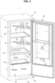
- FIG. 2 is a perspective view illustrating a state in which a door is opened in the shoe care apparatus shown in FIG. 1 .
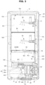
- FIG. 3 is a front cross-sectional view illustrating the shoe care apparatus shown in FIG. 1 .
- the shoe care apparatus 1 may include a main body 10 forming the external appearance and a door 20 rotatably coupled to the main body 10.
- the main body 10 may be provided in a rectangular parallelepiped shape with an open front side.
- An opening 10a may be formed in the open front side of the main body 10.
- the door 20 may be rotatably coupled to the main body 10 to open and close the open front side of the main body 10.
- the door 20 may be coupled to the main body 10 by a hinge 23.
- the main body 10 may be formed such that a front surface extending in a first direction X has a length different from that of a side surface extending in a second direction Y. That is, the front surface of the main body 10 may have a length L1 longer than a length L2 of the side surface of the main body 10. Such a configuration enables the shoe care apparatus 1 to be easily installed even in a narrow entrance hall.
- the length of the front surface of the main body 10 may be defined as a first length L1 and the length of the side surface of the main body 10 may be defined as a second length L2.
- the door 20 may include a control panel 22 provided on a front and/or upper surface of the door 20.
- the control panel 22 may receive various commands from the user.
- the control panel 22 may display various pieces of information regarding the operation of the shoe care apparatus 1. For example, the user may use the control panel 22 to select the type of shoes to be cared for, and set an appropriate care course for the shoes.
- the control panel 22 may include a display for displaying information regarding the operation of the shoe care apparatus 1.
- the control panel 22 may include at least one of a button or a touch screen.
- the door 20 may include a hanging member 21.
- the hanging member 21 may be provided on one side of the door 20 facing the inside of a care room 30, and may be provided in at least one unit thereof.
- the care room 30 may also be referred to as a compartment 30, care area 30, a treatment area 30, or care space 30.
- the hanging member 21 may be used for hanging a handle 55 of a cradle 50.
- the hanging member 21 may facilitate storage of the cradle 50.
- the hanging member 21 may be used for other uses.
- the main body 10 may include an outer case 11 and an inner case 12 arranged inside the outer case 11.
- the care room 30 may be formed inside the main body 10.
- the inner case 12 may form the care room 30.
- the care room 30 may be provided therein with the cradle 50 on which shoes may be held.
- the inner case 12 may be referred to as a case.
- the care room 30 may form a space in which shoes are accommodated.
- the care room 30 may be formed by an upper surface 12a, a lower surface 12b, a left surface 12c, a right surface 12d, and a rear surface 12e of the inner case 12.
- Shoes may be accommodated in the care room 30 and cared.
- the upper surface 12a, the lower surface 12b, the left surface 12c, the right surface 12d, and the rear surface 12e of the inner case 12 may form an upper wall 12a, a lower wall 12b, a left wall 12c, a right wall 12d, and a rear wall 12e of the inner case 12.
- the cradle 50 and a mounting rail 80 may be provided in the care room 30.
- the cradle 50 and the mounting rail 80 may be installed on the left surface 12c or the right surface 12d of the inner case 12. That is, the cradle 50 may be installed such that the side of the shoe is visible when viewed from the front of the shoe care apparatus 1.
- the length of the side surface of the main body 10 may be formed shorter than the length of the front surface of the main body 10.
- the positions of the cradle 50 and the mounting rail 80 are not limited to those illustrated above.
- the cradle 50 may be provided in at least one unit thereof.
- the cradle 50 may be provided in a shape to be inserted into the shoe.
- the cradle 50 is detachable from the care room 30. That is, the cradle 50 may be coupled to the mounting rail 80 provided on the side surface of the care room 30, and may be separated from the mounting rail 80. For example, the cradle 50 may be inserted into the mounting rail 80 along the second direction Y. Because the cradle 50 is detachably provided, the space in the care room 30 may be efficiently used according to the size of the shoe.
- the shoe care apparatus 1 may include an air outlet 31 and an air inlet 60.
- the air outlet 31 may be formed in the sidewall of the inner case 12.
- the air outlet 31 may be formed on the left surface 12c of the care room 30.
- the air outlet 31 may be provided in plural.
- the air outlet 31 may allow air that has passed through a duct 100 to flow into the care room 30.
- air cooled and dehumidified by an evaporator 42 may flow to a condenser 43, and the air may be heated by the condenser 43 and flow into the care room 30 through the air outlet 31.
- the air inlet 60 may be formed on one side surface of the inner case 12.
- the air inlet 60 may be formed on the lower surface 12b of the inner case 12.
- the air inlet 60 may be arranged on a front portion of the lower surface 12b.
- Air in the care room 30 may be introduced into the duct 100 through the air inlet 60.
- the air inlet 60 may include a central hole 60a and a grille 60b including a plurality of side holes.
- the shoe care apparatus 1 may include a machine room 32, a condenser 43, a compressor 41, an evaporator 42, and a communication hole 33.
- the machine room 32 may be provided at one side of the care room 30.
- the machine room 32 may be referred to as compartment 32, machine area 32, and machine space 32.
- the machine room 32 may be provided below the care room 30.
- At least a portion of the duct 100 may be accommodated in the machine room 32.
- a heat pump device 40 including the compressor 41, the expander 44, the evaporator 42, and the condenser 43 may be arranged in the machine room 32.
- the machine room 32 may accommodate the compressor 41, the expander 44, the evaporator 42, and the condenser 43.
- a sterilizing device 49 may be provided in the care room 30 or in the machine room 32. In FIGS. 2 and 3 , the sterilization device 49 is illustrated as being provided inside the care room 30.
- Air inside the machine room 32 may communicate with the air outside of the shoe care apparatus 1 through the communication hole 33.
- the communication hole 33 may be provided in a rear portion of the machine room 32.
- the communication hole 33 may be provided in a rear wall of the main body 10.
- the communication hole 33 may be provided in a rear wall 11e of the outer cabinet 11.
- the disclosure is not limited thereto, and the communication hole 33 may be provided at various positions as long as it can communicate the machine room 32 with the outside of the main body 10.
- the communication holes may be formed on sidewalls 11c and 11d of the outer cabinet 11.
- the duct 100 may be provided at one side of the care room 30.
- the duct 100 may be arranged on the left wall 12c and/or the right wall 12d below the care room 30.
- the duct 100 may be provided at one side of the machine room 32.
- the duct 100 may be arranged on an upper side of the machine room 32.
- the evaporator 42, the condenser 43, the deodorizing device 45, the duct 100, a blower fan 47, a first temperature sensor 110 and a second temperature sensor 120 may be provided.
- the compressor 41, the evaporator 42, the condenser 43, and the expander 44 may be defined as the heat pump device 40.
- a refrigerant may flow through the compressor 41, the evaporator 42, the condenser 43, and the expander 44 through a refrigerant pipe 40a (to be described below) of the heat pump device 40.
- the heat pump device 40 may allow air circulating in the care room 30 to be cooled, dehumidified, and heated.
- the heat pump device 40 may allow air flowing out of the care room 30 to be dehumidified, and allow the air heated through the condenser 43 to be introduced into the care room 30.
- the duct 100 may include a first duct 101 positioned below the care room 30.
- the first duct 101 may be referred to as a lower duct 101.
- the duct 100 may form a passage that is connected to the air inlet 60 of the care room 30 and guides the air passing through the air inlet 60 to the blower fan 47.
- the duct 100 may include a second duct 102 provided on the left wall 12c and/or the right wall 12d forming the care room 30.
- the first duct 101 may be connected to the second duct 102 provided on the sidewall of the main body 10.
- the second duct 102 may be referred to as a side duct 102.
- the second duct 102 may be provided on the outside of the sidewall of the inner case 12 in the second direction Y of the shoe care apparatus 1. One end of the second duct 102 may be connected to the at least one air outlet 31, and the other end of the second duct 102 may be connected to the first duct 101.
- the second duct 102 may form an exhaust passage 104 for guiding air to the air outlet 31.
- the evaporator 42 and the condenser 43 may be arranged in the first duct 101.
- the evaporator 42, the condenser 43, and the blower fan 47 may be arranged in the first direction X.
- the evaporator 42 may be located upstream of the condenser 43 based on the flow of air.
- the blower fan 47 may be provided between the heat pump device 40 and the care room 30 to circulate air.
- the blower fan 47 may rotate based on a predetermined rotation per minute (RPM). Specifically, the blower fan 47 may suction air flowing into the first duct 101 and discharge the air toward the second duct 102.
- the air introduced into the first duct 101 through the air inlet 60 may be dried while passing through the evaporator 42 of the heat pump device 40, heated while passing through the condenser 43, and then discharged back to the care room 30 through the second duct 102 and the air outlet 31.
- the deodorizing device 45 may be arranged in the first duct 101.
- the deodorizing device 45 may include a deodorizing filter 45a and an ultraviolet (UV) LED 45b.
- the deodorizing filter 45a and the UV LED 45b may be arranged at a position close to the air inlet 60 of the care room 30.
- the UV LED 45b may remove the smell of air by irradiating the deodorizing filter 45a with light.
- the deodorizing filter 45a may include at least one of a ceramic filter, a photocatalytic filter, or an activated carbon filter.
- the sterilizing device 49 may be further arranged in the care room 30 or in the first duct 101.
- the sterilizing device 49 may remove bacteria contained in the air.
- the sterilizing device 49 may include at least one of an ultraviolet lamp, an ultraviolet LED, a xenon lamp, an ozone generator, or a sterilizing agent spray.
- a drain container 48 may be arranged on the lower side of the main body 10, that is, on the lower side of the machine room 32.
- the drain container 48 may store condensate water generated by the evaporator 42. That is, air discharged from the care room 30 may be cooled and dehumidified by the evaporator 42 provided in the duct 100, and condensate water generated during cooling and dehumidification may be collected in the drain container 48.
- the drain container 48 may be detachable from the main body 10.
- the drain container 48 may be referred to as a water collecting container 48.
- At least one shelf 90 may be provided in the care room 30. Shoes may be placed on the shelf 90.
- the shelf 90 may include a duct shelf 91.
- the duct shelf 91 may form a duct passage 91b therein, and may be formed with a lower surface hole 91a at a lower surface thereof. Air blown from the blower fan 47 through the second duct 102 may be discharged into the care room 30 through the lower surface hole 91a of the duct shelf 91.
- the duct shelf 91 may be formed with an upper surface hole 93 at an upper surface thereof.
- a side surface of the duct shelf 91 may be connected to a circular duct 92 arranged in the second duct 102. Air may be discharged into the care room 30 through a nozzle 92a of the circular duct 92. Air may be supplied to the duct shelf 91 after passing through the circular duct 92.
- the circular duct 92 may have various shapes.
- the first temperature sensor 110 may measure a first temperature of air heated by the condenser 43.
- the first temperature sensor 110 may be arranged downstream of the condenser 43 to detect the temperature of the air flowing out of the condenser 43.
- the temperature of the air measured by the first temperature sensor 110 is defined as the first temperature.
- the first temperature sensor 110 may be provided in a passage between the condenser 43 and the blower fan 47.
- the position of the first temperature sensor 110 is not limited to the above example.
- the controller 200 of the shoe care apparatus 1 may adjust the operating frequency of the compressor 41 based on the first temperature measured by the first temperature sensor 110.
- the second temperature sensor 120 may measure the temperature of air at the air inlet 60 of the care room 30 and/or the temperature of air before flowing into the evaporator 42.
- the second temperature sensor 120 may be arranged upstream of the evaporator 42 to detect the temperature of the air before flowing into the evaporator 42.
- the second temperature sensor 120 may be provided in a passage between the air inlet 60 and the deodorization filter 45a or between the deodorization filter 45a and the evaporator 42.
- the temperature of air measured by the second temperature sensor 120 is defined as the second temperature.
- the controller 200 of the shoe care apparatus 1 may determine external air temperature based on the second temperature measured by the second temperature sensor 120 when the shoe care apparatus 1 starts to operate.
- FIG. 4 is a schematic diagram illustrating the shoe care apparatus shown in FIG. 1 .
- a circulation passage circulating through the care room 30 and the machine room 32 in the shoe care apparatus 1 shown in FIG. 3 and the flow of air flowing through an internal passage 100a of the duct 100 will be described in detail.
- the shoe care apparatus may include a circulation passage through which air circulates between the care room 30 and the machine room 32, and the blower fan 47 for blowing air in the circulation passage.
- the circulation passage may be a circulation path.
- the circulation passage may include a first circulation passage and a second circulation passage.
- the first circulation passage may include an air supply passage 103, an air exhaust passage 104, and a first passage 105.
- the second circulation passage may include an air supply passage 103, an air exhaust passage 104, and a second passage 106.
- the shoe care apparatus may include the duct 100 and the internal passage 100a provided at one side of the care room 30.
- the duct 100 may include the first duct 101 and the second duct 102.
- the first duct 101 may be provided below the care room 30.
- the second duct 102 may be formed on the sidewalls 12c and 12d forming the care room 30.
- the first duct 101 and the second duct 102 may be connected to each other such that air communicates between each other.
- the first duct 101 and the second duct 102 may be integrally formed with each other.
- the disclosure is not limited thereto, and the first duct 101 and the second duct 102 may be separately formed and coupled to each other.
- the duct 100 may include the passage 100a formed therein.
- the evaporator 42, the condenser 43, and the blower fan 47 may be arranged in the passage 100a.
- the passage 100a may be provided in plural.
- the passage 100a may include the air supply passage 103, the air exhaust passage 104, the first passage 105, the second passage 106, and a third passage 109.
- the air supply passage 103 may be provided such that air in the care room 30 flows into the duct 100.
- the air supply passage 103 may receive air from the air inlet 60 and allow the air to flow to the evaporator 42.
- the air inlet 60 may be formed on the lower surface 12b of the inner case forming the care room 30.
- the air supply passage 103 may be formed from the air inlet 60 to the evaporator 42.
- the first passage 105 may be formed from the air inlet 60 to the upstream side of the evaporator 42.
- the disclosure is not limited thereto, and the evaporator 42 may be a component arranged inside the air supply passage 103.
- the first passage 105 may be formed in the first duct 101.
- the first passage 105 may be provided such that air having passed through the evaporator 42 flows to the condenser 43.
- the first passage 105 may be formed from the evaporator 42 to the blower fan 47.
- the first passage 105 may be formed from the downstream side of the evaporator 42 to the upstream side of the blower fan 47.
- the disclosure is not limited thereto, and the evaporator 42 and the blower fan 47 may be arranged in the first passage 105.
- the condenser 43 may be arranged inside the first passage 105.
- the first passage 105 may serve as a condenser passage 105 or a main passage 105.
- the first temperature sensor 110 may be arranged in the first passage 105.
- the position of the first temperature sensor 110 is not limited thereto.
- the second passage 106 may be formed in the first duct 101.
- the second passage 106 may be separated from the first passage 105 by a partition wall 107. However, at least a portion of the second passage 106 may overlap the first passage 105.
- the second passage 106 is provided such that the air having passed through the evaporator 42 bypasses the condenser 43.
- the second passage 106 may prevent the air having passed through the evaporator 42 from passing through the condenser 43 in a second mode to be described below.
- the second passage 106 may serve as a bypass passage 106.
- the air passing through the evaporator 42 in the duct 100 may not pass through the condenser 43, and the temperature of the care room 30 in which heat accumulation has occurred and surrounding components may be lowered. Accordingly, the dehumidification efficiency of the evaporator 42 may be increased.
- the third passage 109 may be formed by the first duct 101.
- the third passage 109 may be formed by a third passage forming portion 108 protruding toward the machine room 32.
- the third passage 109 allows air inside the machine room 32 to flow to the condenser 43.
- the third passage 109 may allow air in the machine room 32 to pass through the condenser 43 in the second mode to be described below. At least a portion of the third passage 109 may overlap the first passage 105. Due to the third passage 109, air in the machine room 32 may heat-exchange with the condenser 43, and the heated air in the machine room 32 may pass through the communication hole 33 provided in the rear wall of the main body 10 to communicate or heat-exchange with the outside air of the shoe care apparatus 1. Accordingly, the heat in the shoe care apparatus 1 may be discharged to the outside of the shoe care apparatus 1.
- the air exhaust passage 104 may be formed in the duct 100. A portion of the exhaust passage 104 may be formed in the second duct 102. The air exhaust passage 104 may be provided such that air in the duct 100 flows to the care room 30 in which shoes 2 are accommodated. The air exhaust passage 104 may be connected to the air outlet 31 such that the air having passed through the blower fan 47 flows to the care room 30. The air outlets 31 may be formed in the sidewalls 12c and 12d of the inner case forming the care room 30. The air exhaust passage 104 may be formed from the blower fan 47 to the air outlet 31. For example, the first passage 105 may be formed from the downstream side of the blower fan 47 to the air outlet 31. However, the disclosure is not limited thereto, and the blower fan 47 may be a component arranged inside the exhaust passage 104.
- the shoe care apparatus may include dampers 105a, 105b, 106a, 109c, and 109d to open and close the passage 100a.
- the dampers may be referred to as valves 105a, 105b, 106a, 109c, and 109d.
- a plurality of dampers 105a, 105b, 106a, 109c, and 109d may be provided.
- the plurality of dampers 105a, 105b, 106a, 109c, and 109d include the first damper 106a, the second damper 109c, the third damper 109d, the fourth damper 105a, and the fifth damper 105b.
- the first damper 106a may be arranged in the bypass passage 106 to adjust the flow rate of air flowing through the bypass passage 106.
- the first damper 106a may open and close the bypass passage 106.
- the position of the first damper 106a is not limited to the above example, and the first damper 106a may be arranged outside the bypass passage 106 as long as it can open and close the bypass passage 106.
- the second damper 109c and the third damper 109d may open and close the third passage 109 to adjust the flow rate of air flowing through the third passage 109.
- the second damper 109c may open and close an inlet 109a of the third passage 109
- the third damper 109d may open and close an outlet 109b of the third passage 109.
- the second damper 109c and/or the third damper 109d may close the third passage 109 such that air in the machine room 32 does not pass through the condenser 43 in the first mode and/or the normal mode, and may open the third passage 109 such that air in the machine room 32 passes through the condenser 43 in the second mode.
- the air in the machine room 32 may heat-exchange with the condenser 43, and the heated air in the machine room 32 may pass through the communication hole 33 provided in the rear wall of the main body 10 to communicate or heat-exchange with the outside air of the shoe care apparatus 1. Accordingly, the heat in the shoe care apparatus 1 may be discharged to the outside of the shoe care apparatus 1.
- the fourth damper 105a and the fifth damper 105b may open and close the first passage 105 to adjust the flow rate of air flowing through the first passage 105.
- the fourth damper 105a may be arranged upstream of the condenser 43 in the first passage 105.
- the fourth damper 105a may be arranged downstream of the evaporator 42 and upstream of the condenser 43 to adjust the flow rate of air in the first passage 105 that flows through the evaporator 42 to the condenser 43.
- the fifth damper 105b may be arranged downstream of the condenser 43 in the first passage 105.
- the fifth damper 105b may be arranged downstream of the condenser 43 and upstream of the blower fan 47 to adjust the flow rate of air in the first passage 105 that flows through the condenser 43 to the blower fan 47.
- the fourth damper 105a and/or the fifth damper 105b in the first mode and/or in the normal mode, may open the first passage 105 such that air introduced from the care room 30 into the air supply passage 103 through the air inlet 60 flows to the condenser 42.
- the fourth damper 105a and/or the fifth damper 105b in the second mode, may close the first passage 105 such that air introduced from the care room 30 into the air supply passage 103 through the air inlet 60 does not flow into the condenser 42, and may allow the air in the machine room 32 to flow from the inlet 109a of the third passage 109 to the condenser 42 and then to the outlet 109b of the third passage 109.
- the air in the machine room 32 may heat-exchange with the condenser 43, and the heated air in the machine room 32 may pass through the communication hole 33 provided in the rear wall of the main body 10 to communicate or heat-exchange with the outside air of the shoe care apparatus 1. Accordingly, the heat in the shoe care apparatus 1 may be discharged to the outside of the shoe care apparatus 1.
- the machine room 32 may be provided below the care room 30.
- the refrigerant pipe 40a, the compressor 41, and the expander 44 constituting the heat pump device 40 may be arranged in the machine room 32.
- the shoe care apparatus 1 may include a third temperature sensor 130 and a fourth temperature sensor 140.
- the third temperature sensor 130 and the fourth temperature sensor 140 may be arranged adjacent to the refrigerant pipe 40a to detect the temperature of the refrigerant.
- the third temperature sensor 130 may detect the temperature of the refrigerant flowing into the evaporator 42 by passing through the expander 44.
- the fourth temperature sensor 140 may detect the temperature of the refrigerant flowing into the condenser 43 by passing through the compressor 41.
- the shoe care apparatus 1 may include the communication hole 33 for communicating the outside of the main body 10 with the inside of the main body 10.
- the communication hole 33 may be formed in one wall of the main body 10 such that air from the outside of the main body 10 flows into or out of the machine room 32.
- the communication hole 33 may be formed in the right wall 11d and/or the rear wall 11e of the outer cabinet 11.
- the communication hole 33 is illustrated as being formed in the right wall 11d for the sake of convenience of description, but the position of the communication hole 33 is not limited to that shown in the drawings.
- the shoe care apparatus 1 may further include a condenser cooling fan 34.
- the condenser cooling fan 34 may blow air in the third passage 109.
- the condenser cooling fan 34 may allow the air in the machine room 32 to flow to the condenser 43 and then to the machine room 32 again.
- the condenser cooling fan 34 may be arranged in the machine room 32.
- the condenser cooling fan 34 may be arranged downstream of the outlet 109b of the third flow passage 109.
- the disclosure is not limited thereto, and the condenser cooling fan 34 may be arranged at various positions, such as at the inlet 109a of the third flow passage 109.
- FIG. 5 is a control block diagram illustrating a shoe care apparatus according to an embodiment.
- a shoe care apparatus 1 may include a control panel 22, a heat pump device 40, a sensor unit 150, a controller 200, and a damper unit 300.
- the control panel 22 may include at least one of a button or a touch screen, and may receive various commands from a user.
- the control panel 22 may transmit a command (hereinafter, 'a user input') received from the user to the controller 200.
- the heat pump device 40 may include a compressor 41, an evaporator 42, a condenser 43, and an expander 44.
- the heat pump device 40 may transmit operation information (e.g., an operating frequency of the compressor 41) to the controller 200, and the controller 200 may control the heat pump device 40.
- the controller 200 may control the operating frequency of the compressor 41.
- the sensor unit 150 may detect a temperature at each location (e.g., inside the duct 100) of the shoe care apparatus 1.
- the sensor unit 150 may include at least one of a first temperature sensor 110, a second temperature sensor 120, a third temperature sensor 130, or a fourth temperature sensor 140.
- the sensor unit 150 may detect the temperature at each location of the shoe care apparatus 1 and transmit a signal to the controller 200.
- the damper unit 300 may include a plurality of dampers (e.g., a first damper 106a, a second damper 109c, a third damper 109d, a fourth damper 105a, and a fifth damper 105b) to adjust the flow rate of air flowing through a plurality of passages (e.g., a first passage 105, a second passage 106, and a third passage 109) provided in the duct 100.
- a plurality of dampers e.g., a first damper 106a, a second damper 109c, a third damper 109d, a fourth damper 105a, and a fifth damper 105b
- the controller 200 may control opening/closing of at least one damper (e.g., the first damper 106a) among the plurality of dampers included in the damper unit 300.
- at least one damper e.g., the first damper 106a
- the controller 200 may include at least one processor 210 and at least one memory 220, and may control at least one other component of the shoe care apparatus 1.
- the processor 210 may execute software (e.g., a program) to control at least one other component (e.g., the heat pump device 40, the damper unit 300, the blower fan 47, the deodorizing device 45, the condenser cooling fan 34) of the shoe care apparatus 1 connected to the processor 210, and perform various data processing or calculations.
- the processor 210 may store instructions or data received from other components (e.g., the sensor unit 150 and the control panel 22) in a volatile memory, process the instructions or data stored in the volatile memory, and store the result data in a non-volatile memory.
- the processor 210 may include a main processor (e.g., a central processing unit) or an auxiliary processor (e.g., a processor for controlling a heat pump device and a processor for controlling a damper unit) that may be operated independent of or together with the main processor.
- a main processor e.g., a central processing unit
- an auxiliary processor e.g., a processor for controlling a heat pump device and a processor for controlling a damper unit
- the auxiliary processor may be set to use less power than the main processor or specialize in a specified function.
- the auxiliary processor may be implemented separately from or as a part of the main processor.
- the memory 220 may store various pieces of data used by at least one component (e.g., the processor 210 or the sensor unit 150) of the shoe care apparatus 1.
- the data may include, for example, software, and input data or output data regarding instructions related to the software.
- the memory 220 may include a volatile memory or a non-volatile memory.
- the memory 220 may store software (e.g., a program) that, when executed by the processor 210, performs an operation to be described below.
- software e.g., a program
- FIG. 6 is a flowchart showing a method of controlling a damper for each operation mode of a shoe care apparatus according to an embodiment
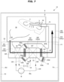
- FIG. 7 illustrates a flow of air when a shoe care apparatus according to an embodiment operates in the first operation mode
- FIG. 8 illustrates a flow of air when a shoe care apparatus according to an embodiment operates in the second operation mode.
- the controller 200 may control various components (e.g., the damper unit 300 and the heat pump device 40) of the shoe care apparatus 1 based on an operation mode of the shoe care apparatus 1 (1000).
- the controller 200 may control opening and closing of the damper unit 300 (e.g., the first damper 106a, the second damper 109c, and the third damper 109d, the fourth damper 105a, and the fifth damper 105b) based on the operation mode of the shoe care apparatus 1.
- the damper unit 300 e.g., the first damper 106a, the second damper 109c, and the third damper 109d, the fourth damper 105a, and the fifth damper 105b
- the operation mode of the shoe care apparatus 1 may include a first operation mode and a second operation mode.
- the first operation mode may refer to an operation mode for drying the shoes 2 accommodated in the care room 30 with high-temperature air that has passed through the condenser 43.
- the second operation mode may refer to an operation mode for cooling the shoes 2 accommodated in the care room 30 with relatively low temperature air that has not passed through the condenser 43, and cooling the heat pump device 40 (e.g., the condenser 43).
- the controller 200 may close the first damper 106a, the second damper 109c, and the third damper 109d in the first mode (1100).
- the controller 200 may open the fourth damper 105a and the fifth damper 105b in the first mode (1110).
- the controller 200 may operate the blower fan 47 and stop the operation of the condenser cooling fan 34 in the first mode.
- the air introduced from the care room 30 and passed through the evaporator 42 may pass through the condenser 43 and then flow back into the care room 30.
- air heated through the condenser 43 may be provided to the shoe 2 to dry the shoe 2 efficiently.
- the controller 200 may close only one (e.g., the first damper 106a) of the first damper 106a, the second damper 109c, and the third damper 109d in the first mode.
- air outside the main body 10 and air inside the main body 10 may communicate with each other through the communication hole 33.
- air outside the main body 10 may flow into or out of the machine room 32.
- the controller 200 may open the first damper 106a, the second damper 109c, and the third damper 109d in the second mode (1200).
- the controller 200 may close the fourth damper 105a and the fifth damper 105b in the second mode (1210).
- the controller 200 may operate the blower fan 47 and the condenser cooling fan 34 in the second mode. In addition, the controller 200 may operate the compressor 41 at the minimum operating frequency in the second mode.
- the first damper 106a, the second damper 109c, and the third damper 109d are opened, and the fourth damper 105a and the fifth damper 105b are closed, the air introduced from the care room 30 and passed through the evaporator 42 may bypass the condenser 43 and flow back into the care room 30 through the second passage 106.
- the shoe 2 in the second mode, may be cooled by circulating the air that has passed through only the evaporator 42 into the care room 30.
- unheated air in the machine room 32 may be used to cool the condenser 43.
- the controller 200 may open the fourth damper 105a and the fifth damper 105b in the second mode, and in this case, the shoe 2 and the condenser 43 may be cooled with a lower efficiency.
- FIG. 9 is a flowchart showing a method of changing an operation mode by a shoe care apparatus according to an embodiment.
- the shoe care apparatus 1 may operate in a first mode (2000).
- the controller 200 may control the damper unit 300 and the heat pump device 40 such that the shoe care apparatus 1 operates in the first mode.
- the controller 200 may adjust the operating frequency of the compressor 41 or control on/off operations of the compressor 41 to follow a target temperature corresponding to the drying course on the basis of temperature information acquired through the sensor unit 150.
- the controller 200 may adjust the operating frequency of the compressor 41 through a fuzzy control method to follow a target temperature corresponding to a drying course.
- the compressor 41 being operated at a preset frequency (e.g., the minimum operating frequency)
- a preset frequency e.g., the minimum operating frequency
- the temperature of the shoe care apparatus 1 e.g., the temperature inside the duct 100 or the temperature inside the care room 30
- a special circumstance e.g., high-temperature outside air
- the dehumidifying performance of the shoe care apparatus 1 may be deteriorated due to high temperature and high humidity air, and a failure of the heat pump device 40 may be caused.
- the controller 200 may determine the operation mode of the shoe care apparatus 1 based on the operating frequency of the compressor 41 and the temperature inside the duct 100.
- the controller 200 based on the operating frequency of the compressor 41 being less than or equal to a preset frequency (YES in operation 2100) and the temperature inside the duct 100 being higher than or equal to a set temperature (YES in operation 2200) while the shoe care apparatus 1 operates in the first mode, may change the operation mode of the shoe care apparatus 1 to the second mode (2300).
- a preset frequency YES in operation 2100
- a set temperature YES in operation 2200
- the operation mode of the shoe care apparatus 1 may be switched to the second mode to cool the condenser 43 and the shoes 2.
- the high-temperature and high-humidity air circulating inside the care room 30 may be changed to low-temperature and low-humidity air, and accordingly the dehumidification performance may be improved.
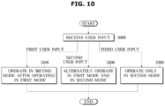
- FIG. 10 is a flowchart showing a method of operating a shoe care apparatus based on a user input according to an embodiment.
- the shoe care apparatus 1 may include the control panel 22 to receive various user inputs from a user.
- the shoe care device 1 may provide a user with various shoe care courses, and the user may select a shoe care course using various buttons and a touch pad included in the control panel 22.
- the shoe care apparatus 1 may provide general drying courses for drying the shoes 2, and may provide various courses, such as a first course for drying and then cooling the shoes 2 , a second course for focusing on dehumidification of the shoes 2, and a third course for cooling the shoe 2.
- a user input for selecting the first course is defined as a first user input
- a user input for selecting the second course is defined as a second user input
- a user input for selecting the third course is defined as a third user input.
- the controller 200 may receive a user input through the control panel 22 (3000), and operate the shoe care apparatus 1 in one of the first mode and the second mode based on the user input.
- the controller 200 may control the shoe care apparatus 1 to operate in the first mode for a first preset time and then operate in the second mode for a second preset time (3100).
- the first preset time may be set as a time for drying the shoe 2
- the second preset time may be set as a time for cooling the shoe 2.
- the first preset time may be set longer than the second preset time.
- the shoe care apparatus 1 may provide the user with the first course, so that when the user wears the shoes 2 immediately after the care has been completed, the user may feel a cooler feeling, thereby increasing the user's satisfaction.
- the first course may be mainly used in summer when the user is uncomfortable to wear the shoes 2 with high temperature.
- the controller 200 may control the shoe care apparatus 1 to alternately operate in the first mode and the second mode for a preset number of times based on reception of the second user input (3200).
- the controller 200 may repeat a cycle several times in which the shoe care apparatus 1 operates in the first mode for a first reference time and operates in the second mode for a second reference time.
- the first reference time and the second reference time may be preset to a time for maximizing the dehumidification performance.
- air that has been heated and humidified by passing through the care room 30, the evaporator 42, and the condenser 43 in the first mode may be caused to pass through only the evaporator 42 in the second mode so that the air may come to have a lowered humidity, and in the next first mode, high temperature and low humidity air may be supplied to the shoes 2, so that the moisture of the shoes 2 may be efficiently removed.
- the shoe care apparatus 1 may provide the user with the second course to thereby remove moisture from the shoes 2 with an optimal time
- the controller 200 may control the shoe care apparatus 1 to operate only in the second mode based on receiving the third user input (3300).
- the controller 200 may control the shoe care apparatus 1 to operate in the second mode for a preset time.
- the preset time may be set in advance as a time suitable for cooling the shoe 2.
- the shoe care apparatus 1 provides the user with the third course, so that when the user wears the shoes 2, the user feels cool, thereby increasing the user's satisfaction.
- the third course may be mainly used in summer when the user is uncomfortable to wear shoes 2 with high temperature.
- the shoe care apparatus 1 may provide the user with various courses by appropriately using the first mode and the second mode, thereby improving the user's satisfaction.
Landscapes
- Engineering & Computer Science (AREA)
- Mechanical Engineering (AREA)
- General Engineering & Computer Science (AREA)
- Footwear And Its Accessory, Manufacturing Method And Apparatuses (AREA)
Claims (15)
- Schuhpflegevorrichtung (1), umfassend:einen Hauptkörper (10);ein erstes Fach (30) im Hauptkörper (10), das zur Aufnahme von Schuhen konfiguriert ist;ein zweites Fach (32) im Hauptkörper (10), das zur Aufnahme einer Wärmepumpe (40) konfiguriert ist, die einen Verdampfer (42) und einen Kondensator (43) umfasst;ein Gebläse (47), das so konfiguriert ist, dass es Luft durch das erste Fach (30) und das zweite Fach (32) zirkulieren lässt;einen ersten Zirkulationskanal (105), der konfiguriert ist, um aus dem ersten Fach (30) ausgestoßene Luft zurück in das erste Fach (30) zu leiten, indem die ausgestoßene Luft zum Verdampfer (42) und zum Kondensator (43) geleitet wird;einen zweiten Zirkulationskanal (106), um die aus dem ersten Fach (30) ausgestoßene Luft zurück in das erste Fach (30) zu leiten, indem die ausgestoßene Luft zum Verdampfer (42) geleitet und der Kondensator (43) umgangen wird;einen dritten Zirkulationskanal (109), um Luft innerhalb des zweiten Fachs (32) so zu leiten, dass sie zum Kondensator (43) strömt; undein erstes Ventil (106a), das zum Öffnen und Schließen des zweiten Zirkulationskanals (106) konfiguriert ist.
- Schuhpflegevorrichtung (1) nach Anspruch 1, ferner umfassend:ein Kommunikationsloch (33), das in einer Wand (11d, 11e) des Hauptkörpers (10) ausgebildet ist, damit eine Außenseite des Hauptkörpers (10) mit dem zweiten Fach (32) kommunizieren kann;einen Einlass (60), durch den Luft, die durch das Kommunikationsloch (33) in das zweite Fach (32) eingeführt wird, zum Kondensator (43) strömt; undeinen ausgebildeten Auslass (31), durch den die durch den Einlass (60) eingeführte Luft durch den Kondensator (43) strömt und dann in das zweite Fach (32) strömt, und in dem die durch den Auslass (31) abgeleitete Luft durch das Kommunikationsloch (33) nach außerhalb des Hauptkörpers (10) abgeleitet wird.
- Schuhpflegevorrichtung (1) nach Anspruch 2, ferner umfassend mindestens eines von einem zweiten Ventil (109c), das zum Öffnen und Schließen des Einlasses (60) konfiguriert ist, oder einem dritten Ventil (109d), das zum Öffnen und Schließen des Auslasses (31) konfiguriert ist.
- Schuhpflegevorrichtung (1) nach Anspruch 1, ferner umfassend ein viertes Ventil (105a), das zwischen dem Verdampfer (42) und dem Kondensator (43) am ersten Zirkulationskanal (105) angeordnet ist.
- Schuhpflegevorrichtung (1) nach Anspruch 4, ferner umfassend eine Steuerung (200), die so konfiguriert ist, dass sie einen Betrieb des ersten Ventils (106a) und einen Betrieb des vierten Ventils (105a) steuert.
- Schuhpflegevorrichtung (1) nach Anspruch 5, wobei die Steuerung (200) konfiguriert ist zum:Steuern des Betriebs des ersten Ventils (106a) und des Betriebs des vierten Ventils (105a), sodass der zweite Zirkulationskanal (106) geschlossen ist, wenn der erste Zirkulationskanal (105) geöffnet ist; undSteuern des Betriebs des ersten Ventils (106a) und des Betriebs des vierten Ventils (105a), sodass der zweite Zirkulationskanal (106) geöffnet wird, wenn der erste Zirkulationskanal (105) geschlossen ist.
- Schuhpflegevorrichtung (1) nach Anspruch 5, wobei die Steuerung (200) konfiguriert ist zum:
Steuern des Betriebs des ersten Ventils (106a) und des Betriebs des vierten Ventils (105a) basierend auf mindestens einem einer Betriebsfrequenz eines Kompressors (41) der Wärmepumpe (40) oder einer Temperatur der dem ersten Fach (30) zugeführten Luft. - Schuhpflegevorrichtung (1) nach Anspruch 7, wobei die Steuerung (200) so konfiguriert ist, dass sie den Betrieb des zweiten Ventils (109c) und den Betrieb des dritten Ventils (109d) basierend auf der Temperatur der dem ersten Fach (30) zugeführten Luft steuert.
- Verfahren zur Steuerung einer Schuhpflegevorrichtung (1) nach Anspruch 1, die in einem ersten Modus arbeitet, in dem Luft, die durch einen Kondensator (43) einer Wärmepumpe (40) geleitet wird, einem Fach (30) zugeführt wird, und in einem zweiten Modus, in dem Luft unter Umgehung des Kondensators (43) dem Fach (30) zugeführt wird, wobei das Verfahren umfasst:als Reaktion auf den Betrieb der Schuhpflegevorrichtung (1) im ersten Modus, Öffnen eines ersten Zirkulationskanals (105), um aus dem Fach (30) ausgestoßene Luft zurück in das Fach (30) zu leiten, indem die ausgestoßene Luft zu einem Verdampfer (42) der Wärmepumpe (40) und dem Kondensator (43) geleitet wird; undals Reaktion auf den Betrieb der Schuhpflegevorrichtung (1) im zweiten Modus, Öffnen eines zweiten Zirkulationskanals (106), um aus dem Fach (30) ausgestoßene Luft zurück in das Fach (30) zu leiten, indem die ausgestoßene Luft zum Verdampfer (42) geleitet und der Kondensator (43) umgangen wird.
- Verfahren nach Anspruch 9, ferner umfassend das Bestimmen eines Betriebsmodus der Schuhpflegevorrichtung (1) basierend auf mindestens einem einer Betriebsfrequenz eines Kompressors (41) und einer Temperatur der dem Fach (30) zugeführten Luft.
- Verfahren nach Anspruch 10, wobei das Bestimmen eines Betriebsmodus der Schuhpflegevorrichtung (1) basierend auf mindestens einem einer Betriebsfrequenz des Kompressors (41) und einer Temperatur der dem Fach (30) zugeführten Luft beinhaltet,
basierend auf der Betriebsfrequenz des Kompressors (41), die kleiner oder gleich einer voreingestellten Frequenz ist, und der Temperatur der dem Fach (30) zugeführten Luft, die höher oder gleich einer eingestellten Temperatur ist, während die Schuhpflegevorrichtung (1) im ersten Modus arbeitet, den Betriebsmodus der Schuhpflegevorrichtung (1) in den zweiten Modus zu ändern. - Verfahren nach Anspruch 9, ferner umfassend das Betreiben der Schuhpflegevorrichtung (1) in einem dem ersten Modus oder dem zweiten Modus basierend auf einer Benutzereingabe.
- Verfahren nach Anspruch 12, wobei der auf der Benutzereingabe basierende Betrieb der Schuhpflegevorrichtung (1) in einem dem ersten Modus und dem zweiten Modus umfasst
basierend auf einer ersten Benutzereingabe, die empfangen wird, Steuern der Schuhpflegevorrichtung (1), um im ersten Modus für eine erste voreingestellte Zeit zu arbeiten und dann im zweiten Modus für eine zweite voreingestellte Zeit zu arbeiten. - Verfahren nach Anspruch 12, wobei der auf der Benutzereingabe basierende Betrieb der Schuhpflegevorrichtung (1) in einem dem ersten Modus und dem zweiten Modus umfasst
basierend auf einer ersten Benutzereingabe, die empfangen wird, Steuern der Schuhpflegevorrichtung (1), um abwechselnd im ersten Modus und im zweiten Modus zu arbeiten. - Verfahren nach Anspruch 12, wobei der auf der Benutzereingabe basierende Betrieb der Schuhpflegevorrichtung (1) in einem dem ersten Modus und dem zweiten Modus umfasst
basierend auf einer ersten Benutzereingabe, die empfangen wird, Steuern der Schuhpflegevorrichtung (1), um für eine voreingestellte Zeit nur im zweiten Modus zu arbeiten.
Applications Claiming Priority (3)
| Application Number | Priority Date | Filing Date | Title |
|---|---|---|---|
| KR20210052577 | 2021-04-22 | ||
| KR1020210090703A KR102901133B1 (ko) | 2021-04-22 | 2021-07-12 | 신발관리기 및 그 제어방법 |
| PCT/KR2021/013012 WO2022225110A1 (ko) | 2021-04-22 | 2021-09-24 | 신발관리기 및 그 제어방법 |
Publications (4)
| Publication Number | Publication Date |
|---|---|
| EP4238474A1 EP4238474A1 (de) | 2023-09-06 |
| EP4238474A4 EP4238474A4 (de) | 2024-06-26 |
| EP4238474C0 EP4238474C0 (de) | 2025-06-25 |
| EP4238474B1 true EP4238474B1 (de) | 2025-06-25 |
Family
ID=83694730
Family Applications (1)
| Application Number | Title | Priority Date | Filing Date |
|---|---|---|---|
| EP21938026.8A Active EP4238474B1 (de) | 2021-04-22 | 2021-09-24 | Schuhverwaltungsvorrichtung und steuerungsverfahren dafür |
Country Status (2)
| Country | Link |
|---|---|
| US (1) | US12318055B2 (de) |
| EP (1) | EP4238474B1 (de) |
Families Citing this family (5)
| Publication number | Priority date | Publication date | Assignee | Title |
|---|---|---|---|---|
| EP4238474B1 (de) * | 2021-04-22 | 2025-06-25 | Samsung Electronics Co., Ltd. | Schuhverwaltungsvorrichtung und steuerungsverfahren dafür |
| KR102702856B1 (ko) * | 2021-12-17 | 2024-09-04 | 엘지전자 주식회사 | 신발 관리기 |
| USD1084564S1 (en) * | 2022-08-26 | 2025-07-15 | Lg Electronics Inc. | Combined deodorizing, sterilizing and steaming apparatus for shoes management |
| WO2024172243A1 (ko) * | 2023-02-14 | 2024-08-22 | 엘지전자 주식회사 | 신발 관리기 |
| USD1066832S1 (en) * | 2024-03-13 | 2025-03-11 | Samsung Electronics Co., Ltd. | Clothing care machine |
Family Cites Families (63)
| Publication number | Priority date | Publication date | Assignee | Title |
|---|---|---|---|---|
| US1678139A (en) * | 1923-02-10 | 1928-07-24 | United Shoe Machinery Corp | Method of and apparatus for softening shoe materials |
| US3078526A (en) * | 1961-10-11 | 1963-02-26 | John S Caruso | Disinfecting apparatus for shoes and the like |
| US5369892A (en) * | 1993-06-04 | 1994-12-06 | Dhaemers; Gregory L. | Armoire |
| KR950024772A (ko) | 1994-02-25 | 1995-09-15 | 주동규 | 신발의 살균, 건조 및 악취제거 장치 |
| KR200250736Y1 (ko) | 2001-07-28 | 2001-11-22 | 김호천 | 신발 건조기 |
| US6766594B2 (en) * | 2002-11-08 | 2004-07-27 | Scientific Molding Corporation | Dryer apparatus for boots and gloves |
| KR100459193B1 (ko) | 2002-11-27 | 2004-12-03 | 엘지전자 주식회사 | 응축식 의류 건조기용 응축기의 냉각 유로 |
| JP2004239549A (ja) | 2003-02-07 | 2004-08-26 | Matsushita Electric Ind Co Ltd | 衣類乾燥装置 |
| KR100681425B1 (ko) | 2004-11-03 | 2007-02-15 | 주식회사 대립 | 신발 건조방법 및 장치 |
| KR100696397B1 (ko) | 2005-08-13 | 2007-03-19 | (주)나눅스 | 신발용 냉각기 |
| US7921578B2 (en) * | 2005-12-30 | 2011-04-12 | Whirlpool Corporation | Nebulizer system for a fabric treatment appliance |
| JP4791881B2 (ja) | 2006-05-12 | 2011-10-12 | 株式会社東芝 | 衣類乾燥機 |
| US20100005681A1 (en) | 2006-07-28 | 2010-01-14 | Seong Jin Jo | Multiple laundry treating machine |
| KR100808199B1 (ko) | 2006-07-28 | 2008-02-29 | 엘지전자 주식회사 | 복합 의류 처리 장치 |
| KR101265621B1 (ko) | 2006-08-22 | 2013-05-22 | 엘지전자 주식회사 | 다층 분할식 건조기 |
| KR200433313Y1 (ko) | 2006-09-22 | 2006-12-08 | 임채경 | 자동 신발청소기 겸용 수납장 |
| KR100795207B1 (ko) | 2006-09-22 | 2008-01-16 | 임채경 | 자동 신발청소기 겸용 수납장 |
| KR100840737B1 (ko) | 2007-01-22 | 2008-06-24 | 김정순 | 신발용 건조 및 소독장치 |
| KR100826537B1 (ko) | 2007-02-23 | 2008-05-02 | 엘지전자 주식회사 | 열교환기 및 이를 포함한 응축식 의류건조기 |
| KR101069827B1 (ko) | 2008-09-17 | 2011-10-04 | 제주특별자치도(농업기술원) | 히트펌프를 이용한 건조기 |
| US8984766B2 (en) * | 2009-08-19 | 2015-03-24 | Williams Boot & Glove Dryers Inc. | Boot and glove dryer for food service industry and method of making same |
| KR20110098092A (ko) | 2010-02-26 | 2011-09-01 | 김근호 | 의복과 신발을 소독/건조/냄새제거 하기 위한 간이장치 |
| KR101337699B1 (ko) | 2010-08-11 | 2013-12-06 | 위니아만도 주식회사 | 의류건조기 및 의류건조기 제어방법 |
| JP5625883B2 (ja) | 2010-12-21 | 2014-11-19 | パナソニック株式会社 | 除湿加温装置および同装置を備えた衣類乾燥機 |
| KR20130010177A (ko) | 2011-07-18 | 2013-01-28 | 위니아만도 주식회사 | 의류건조기 |
| KR20130018068A (ko) | 2011-08-12 | 2013-02-20 | 김종득 | 신발 세척장치 |
| KR200457168Y1 (ko) | 2011-08-23 | 2011-12-07 | (주)아성온 | 신발 소독장치 |
| KR20130026835A (ko) | 2011-09-06 | 2013-03-14 | 주식회사 엘지생활건강 | 휴대용 의류 처리 장치 |
| EP2573252B1 (de) * | 2011-09-26 | 2014-05-07 | Electrolux Home Products Corporation N.V. | Wäschebehandlungsvorrichtung mit Wärmepumpe |
| KR20130035627A (ko) | 2011-09-30 | 2013-04-09 | 양혜진 | 다용도 살균장치 |
| US9869052B2 (en) | 2011-11-08 | 2018-01-16 | Haier Group Corporation | Heat exchanger for condensation in clothes drying and clothes drying system and clothes dryer and drying method thereof |
| CN102517861B (zh) | 2011-12-19 | 2017-09-26 | 青岛海尔滚筒洗衣机有限公司 | 干衣温度检测控制方法及干衣机 |
| US9103588B2 (en) * | 2012-01-19 | 2015-08-11 | Williams Boot & Glove Dryers Inc. | Dryer for gas masks |
| KR101318056B1 (ko) | 2012-11-07 | 2013-10-14 | 김광석 | 신발 건조기 |
| KR20140127986A (ko) | 2013-04-26 | 2014-11-05 | 김광석 | 신발 건조기 |
| CN104911882B (zh) | 2014-03-14 | 2018-10-30 | 青岛海尔滚筒洗衣机有限公司 | 一种干衣机或洗干一体机 |
| KR101661393B1 (ko) | 2014-04-10 | 2016-09-29 | (주) 크렌즈 | 스팀을 이용한 신발의 살균,탈취,건조기 |
| KR101636711B1 (ko) * | 2014-07-03 | 2016-07-08 | 길라씨엔아이 주식회사 | 건조기 |
| KR101594260B1 (ko) | 2014-11-10 | 2016-02-15 | 이현정 | 세탁물 건조기 |
| JP2016104111A (ja) | 2014-11-19 | 2016-06-09 | 三星電子株式会社Samsung Electronics Co.,Ltd. | 乾燥機 |
| KR101632013B1 (ko) | 2014-12-08 | 2016-06-21 | 엘지전자 주식회사 | 히트펌프 사이클을 구비한 응축식 의류 건조기 및 이의 제어방법 |
| KR101613963B1 (ko) | 2014-12-08 | 2016-04-20 | 엘지전자 주식회사 | 히트펌프 사이클을 구비한 의류처리장치 |
| KR101711869B1 (ko) | 2015-01-13 | 2017-03-03 | 엘지전자 주식회사 | 건조기 |
| CN105986454A (zh) | 2015-02-04 | 2016-10-05 | 青岛海尔洗衣机有限公司 | 一种空气冷凝器及干衣机 |
| KR102602847B1 (ko) * | 2016-06-03 | 2023-11-16 | 엘지전자 주식회사 | 의류처리장치 |
| US10197332B2 (en) * | 2016-06-28 | 2019-02-05 | Lawrence A. Hinkey | Apparel drying assemblies and methods of drying apparel |
| US10724744B2 (en) | 2016-09-21 | 2020-07-28 | Lennox Industries Inc. | Method and apparatus for reduction of water re-evaporation in a dedicated dehumidifier/water heater |
| US10406885B2 (en) * | 2017-04-27 | 2019-09-10 | Denso International America, Inc. | HVAC unit including blowers for directing airflow through the HVAC unit |
| KR101889821B1 (ko) | 2017-10-17 | 2018-08-20 | 신훈휴 | 신발 관리 서비스 제공 시스템 및 방법 |
| KR102004349B1 (ko) | 2018-02-26 | 2019-07-26 | 조영철 | 신발 세척장치 |
| KR20200002371A (ko) | 2018-06-29 | 2020-01-08 | 한창수 | 운동화 물기 제거기 |
| KR102653613B1 (ko) | 2019-08-06 | 2024-04-01 | 엘지전자 주식회사 | 신발 관리 장치 및 이를 이용한 신발 관리 방법 |
| KR20210016968A (ko) | 2019-08-06 | 2021-02-17 | 엘지전자 주식회사 | 신발 관리 장치 및 이를 이용한 신발 관리 방법 |
| KR102663644B1 (ko) | 2019-08-06 | 2024-05-03 | 엘지전자 주식회사 | 신발 관리 장치 |
| CN114390905B (zh) * | 2019-09-10 | 2024-12-06 | 三星电子株式会社 | 鞋干燥机及其控制方法 |
| JP2021040909A (ja) * | 2019-09-10 | 2021-03-18 | 三星電子株式会社Samsung Electronics Co.,Ltd. | 靴乾燥機及びその制御方法 |
| KR102310173B1 (ko) | 2019-10-22 | 2021-10-08 | (주)미래테크닉스 | 신발 내부 및 외부의 살균소독을 위한 슈즈 케어 장치 |
| KR20200002725A (ko) | 2019-12-13 | 2020-01-08 | 동아대학교 산학협력단 | 살균 및 탈취 기능을 구비한 신발건조기 |
| KR20200130463A (ko) | 2020-08-13 | 2020-11-18 | 쿠웨이브 (난징) 소프트웨어 테크놀로지 컴퍼니., 리미티드 | 신발 건조 장치 |
| KR102230674B1 (ko) | 2021-02-16 | 2021-03-19 | 윤홍중 | 신발용 살균, 탈취, 건조장치 |
| EP4238474B1 (de) * | 2021-04-22 | 2025-06-25 | Samsung Electronics Co., Ltd. | Schuhverwaltungsvorrichtung und steuerungsverfahren dafür |
| KR20220163193A (ko) | 2021-06-02 | 2022-12-09 | 삼성전자주식회사 | 신발 관리기 및 그 제어 방법 |
| EP4335350A4 (de) * | 2021-07-29 | 2024-10-23 | Samsung Electronics Co., Ltd. | Schuhpflegevorrichtung und steuerungsverfahren dafür |
-
2021
- 2021-09-24 EP EP21938026.8A patent/EP4238474B1/de active Active
- 2021-12-23 US US17/560,677 patent/US12318055B2/en active Active
Also Published As
| Publication number | Publication date |
|---|---|
| US12318055B2 (en) | 2025-06-03 |
| US20220338711A1 (en) | 2022-10-27 |
| EP4238474C0 (de) | 2025-06-25 |
| EP4238474A1 (de) | 2023-09-06 |
| EP4238474A4 (de) | 2024-06-26 |
Similar Documents
| Publication | Publication Date | Title |
|---|---|---|
| EP4238474B1 (de) | Schuhverwaltungsvorrichtung und steuerungsverfahren dafür | |
| US20090119848A1 (en) | Clothes treating machine and method for controlling the same | |
| KR102891197B1 (ko) | 의류 관리기 및 그 제어 방법 | |
| KR101414635B1 (ko) | 의류처리장치 | |
| CN101416000B (zh) | 除湿机 | |
| KR20090105080A (ko) | 의류처리장치 및 그 제어방법 | |
| KR20180128549A (ko) | 옷장 | |
| KR20210049449A (ko) | 공기조화기 및 그 제어방법 | |
| JPH0956992A (ja) | 衣類乾燥装置 | |
| JP4285959B2 (ja) | 空気調和機 | |
| KR102901133B1 (ko) | 신발관리기 및 그 제어방법 | |
| KR101420873B1 (ko) | 공기 조화 장치 | |
| KR102917593B1 (ko) | 공기 조화기 및 그 제어 방법 | |
| KR102190386B1 (ko) | 드레스룸 환경조성장치 | |
| JPH0336433A (ja) | 空気調和機 | |
| JP4938536B2 (ja) | 空気調和機 | |
| JP2001062194A (ja) | 衣類乾燥機 | |
| US20240122442A1 (en) | Shoe care device and control method thereof | |
| US20230204230A1 (en) | Air conditioner and control method thereof | |
| CN116648177A (zh) | 鞋管理设备及其控制方法 | |
| KR102412956B1 (ko) | 공기 조화기 및 이를 포함하는 공기조화 시스템 | |
| KR101362664B1 (ko) | 공기 조화 장치 | |
| KR102927284B1 (ko) | 신발관리기 및 그 제어방법 | |
| KR101204001B1 (ko) | 공기조화기의 가습 제어장치 및 그 방법 | |
| US20250264229A1 (en) | Air cleaner |
Legal Events
| Date | Code | Title | Description |
|---|---|---|---|
| STAA | Information on the status of an ep patent application or granted ep patent |
Free format text: STATUS: THE INTERNATIONAL PUBLICATION HAS BEEN MADE |
|
| PUAI | Public reference made under article 153(3) epc to a published international application that has entered the european phase |
Free format text: ORIGINAL CODE: 0009012 |
|
| STAA | Information on the status of an ep patent application or granted ep patent |
Free format text: STATUS: REQUEST FOR EXAMINATION WAS MADE |
|
| 17P | Request for examination filed |
Effective date: 20230530 |
|
| AK | Designated contracting states |
Kind code of ref document: A1 Designated state(s): AL AT BE BG CH CY CZ DE DK EE ES FI FR GB GR HR HU IE IS IT LI LT LU LV MC MK MT NL NO PL PT RO RS SE SI SK SM TR |
|
| A4 | Supplementary search report drawn up and despatched |
Effective date: 20240528 |
|
| RIC1 | Information provided on ipc code assigned before grant |
Ipc: F26B 25/00 20060101ALI20240522BHEP Ipc: F26B 21/00 20060101ALI20240522BHEP Ipc: F26B 21/08 20060101ALI20240522BHEP Ipc: F26B 21/02 20060101ALI20240522BHEP Ipc: A47L 23/18 20060101ALI20240522BHEP Ipc: A47L 23/20 20060101AFI20240522BHEP |
|
| DAV | Request for validation of the european patent (deleted) | ||
| DAX | Request for extension of the european patent (deleted) | ||
| GRAP | Despatch of communication of intention to grant a patent |
Free format text: ORIGINAL CODE: EPIDOSNIGR1 |
|
| STAA | Information on the status of an ep patent application or granted ep patent |
Free format text: STATUS: GRANT OF PATENT IS INTENDED |
|
| INTG | Intention to grant announced |
Effective date: 20250127 |
|
| GRAS | Grant fee paid |
Free format text: ORIGINAL CODE: EPIDOSNIGR3 |
|
| GRAA | (expected) grant |
Free format text: ORIGINAL CODE: 0009210 |
|
| STAA | Information on the status of an ep patent application or granted ep patent |
Free format text: STATUS: THE PATENT HAS BEEN GRANTED |
|
| AK | Designated contracting states |
Kind code of ref document: B1 Designated state(s): AL AT BE BG CH CY CZ DE DK EE ES FI FR GB GR HR HU IE IS IT LI LT LU LV MC MK MT NL NO PL PT RO RS SE SI SK SM TR |
|
| REG | Reference to a national code |
Ref country code: GB Ref legal event code: FG4D |
|
| REG | Reference to a national code |
Ref country code: CH Ref legal event code: EP |
|
| REG | Reference to a national code |
Ref country code: CH Ref legal event code: EP |
|
| REG | Reference to a national code |
Ref country code: IE Ref legal event code: FG4D |
|
| REG | Reference to a national code |
Ref country code: DE Ref legal event code: R096 Ref document number: 602021033119 Country of ref document: DE |
|
| U01 | Request for unitary effect filed |
Effective date: 20250721 |
|
| U07 | Unitary effect registered |
Designated state(s): AT BE BG DE DK EE FI FR IT LT LU LV MT NL PT RO SE SI Effective date: 20250728 |
|
| PG25 | Lapsed in a contracting state [announced via postgrant information from national office to epo] |
Ref country code: NO Free format text: LAPSE BECAUSE OF FAILURE TO SUBMIT A TRANSLATION OF THE DESCRIPTION OR TO PAY THE FEE WITHIN THE PRESCRIBED TIME-LIMIT Effective date: 20250925 Ref country code: GR Free format text: LAPSE BECAUSE OF FAILURE TO SUBMIT A TRANSLATION OF THE DESCRIPTION OR TO PAY THE FEE WITHIN THE PRESCRIBED TIME-LIMIT Effective date: 20250926 |
|
| PGFP | Annual fee paid to national office [announced via postgrant information from national office to epo] |
Ref country code: GB Payment date: 20250820 Year of fee payment: 5 |
|
| PG25 | Lapsed in a contracting state [announced via postgrant information from national office to epo] |
Ref country code: HR Free format text: LAPSE BECAUSE OF FAILURE TO SUBMIT A TRANSLATION OF THE DESCRIPTION OR TO PAY THE FEE WITHIN THE PRESCRIBED TIME-LIMIT Effective date: 20250625 |
|
| PG25 | Lapsed in a contracting state [announced via postgrant information from national office to epo] |
Ref country code: RS Free format text: LAPSE BECAUSE OF FAILURE TO SUBMIT A TRANSLATION OF THE DESCRIPTION OR TO PAY THE FEE WITHIN THE PRESCRIBED TIME-LIMIT Effective date: 20250925 |
|
| U20 | Renewal fee for the european patent with unitary effect paid |
Year of fee payment: 5 Effective date: 20250924 |
|
| PG25 | Lapsed in a contracting state [announced via postgrant information from national office to epo] |
Ref country code: IS Free format text: LAPSE BECAUSE OF FAILURE TO SUBMIT A TRANSLATION OF THE DESCRIPTION OR TO PAY THE FEE WITHIN THE PRESCRIBED TIME-LIMIT Effective date: 20251025 |
|
| PG25 | Lapsed in a contracting state [announced via postgrant information from national office to epo] |
Ref country code: SM Free format text: LAPSE BECAUSE OF FAILURE TO SUBMIT A TRANSLATION OF THE DESCRIPTION OR TO PAY THE FEE WITHIN THE PRESCRIBED TIME-LIMIT Effective date: 20250625 |
|
| PG25 | Lapsed in a contracting state [announced via postgrant information from national office to epo] |
Ref country code: CZ Free format text: LAPSE BECAUSE OF FAILURE TO SUBMIT A TRANSLATION OF THE DESCRIPTION OR TO PAY THE FEE WITHIN THE PRESCRIBED TIME-LIMIT Effective date: 20250625 |
|
| PG25 | Lapsed in a contracting state [announced via postgrant information from national office to epo] |
Ref country code: PL Free format text: LAPSE BECAUSE OF FAILURE TO SUBMIT A TRANSLATION OF THE DESCRIPTION OR TO PAY THE FEE WITHIN THE PRESCRIBED TIME-LIMIT Effective date: 20250625 |
|
| PG25 | Lapsed in a contracting state [announced via postgrant information from national office to epo] |
Ref country code: SK Free format text: LAPSE BECAUSE OF FAILURE TO SUBMIT A TRANSLATION OF THE DESCRIPTION OR TO PAY THE FEE WITHIN THE PRESCRIBED TIME-LIMIT Effective date: 20250625 |
|
| PG25 | Lapsed in a contracting state [announced via postgrant information from national office to epo] |
Ref country code: ES Free format text: LAPSE BECAUSE OF FAILURE TO SUBMIT A TRANSLATION OF THE DESCRIPTION OR TO PAY THE FEE WITHIN THE PRESCRIBED TIME-LIMIT Effective date: 20250625 |