EP4231875B1 - Schubvorrichtung und verfahren zur montage einer schubvorrichtung - Google Patents
Schubvorrichtung und verfahren zur montage einer schubvorrichtung Download PDFInfo
- Publication number
- EP4231875B1 EP4231875B1 EP21790107.3A EP21790107A EP4231875B1 EP 4231875 B1 EP4231875 B1 EP 4231875B1 EP 21790107 A EP21790107 A EP 21790107A EP 4231875 B1 EP4231875 B1 EP 4231875B1
- Authority
- EP
- European Patent Office
- Prior art keywords
- holder
- pull
- pushing device
- holders
- side wall
- Prior art date
- Legal status (The legal status is an assumption and is not a legal conclusion. Google has not performed a legal analysis and makes no representation as to the accuracy of the status listed.)
- Active
Links
Images



Classifications
-
- A—HUMAN NECESSITIES
- A47—FURNITURE; DOMESTIC ARTICLES OR APPLIANCES; COFFEE MILLS; SPICE MILLS; SUCTION CLEANERS IN GENERAL
- A47B—TABLES; DESKS; OFFICE FURNITURE; CABINETS; DRAWERS; GENERAL DETAILS OF FURNITURE
- A47B88/00—Drawers for tables, cabinets or like furniture; Guides for drawers
- A47B88/40—Sliding drawers; Slides or guides therefor
- A47B88/423—Fastening devices for slides or guides
- A47B88/427—Fastening devices for slides or guides at drawer side
-
- F—MECHANICAL ENGINEERING; LIGHTING; HEATING; WEAPONS; BLASTING
- F25—REFRIGERATION OR COOLING; COMBINED HEATING AND REFRIGERATION SYSTEMS; HEAT PUMP SYSTEMS; MANUFACTURE OR STORAGE OF ICE; LIQUEFACTION SOLIDIFICATION OF GASES
- F25D—REFRIGERATORS; COLD ROOMS; ICE-BOXES; COOLING OR FREEZING APPARATUS NOT OTHERWISE PROVIDED FOR
- F25D25/00—Charging, supporting, and discharging the articles to be cooled
- F25D25/02—Charging, supporting, and discharging the articles to be cooled by shelves
- F25D25/024—Slidable shelves
- F25D25/025—Drawers
-
- A—HUMAN NECESSITIES
- A47—FURNITURE; DOMESTIC ARTICLES OR APPLIANCES; COFFEE MILLS; SPICE MILLS; SUCTION CLEANERS IN GENERAL
- A47B—TABLES; DESKS; OFFICE FURNITURE; CABINETS; DRAWERS; GENERAL DETAILS OF FURNITURE
- A47B88/00—Drawers for tables, cabinets or like furniture; Guides for drawers
- A47B88/40—Sliding drawers; Slides or guides therefor
- A47B2088/401—Slides or guides for wire baskets
-
- A—HUMAN NECESSITIES
- A47—FURNITURE; DOMESTIC ARTICLES OR APPLIANCES; COFFEE MILLS; SPICE MILLS; SUCTION CLEANERS IN GENERAL
- A47B—TABLES; DESKS; OFFICE FURNITURE; CABINETS; DRAWERS; GENERAL DETAILS OF FURNITURE
- A47B88/00—Drawers for tables, cabinets or like furniture; Guides for drawers
- A47B88/40—Sliding drawers; Slides or guides therefor
- A47B88/423—Fastening devices for slides or guides
- A47B88/427—Fastening devices for slides or guides at drawer side
- A47B2088/4274—Fastening devices for slides or guides at drawer side the drawer being detachable as a whole from a slide frame
-
- A—HUMAN NECESSITIES
- A47—FURNITURE; DOMESTIC ARTICLES OR APPLIANCES; COFFEE MILLS; SPICE MILLS; SUCTION CLEANERS IN GENERAL
- A47B—TABLES; DESKS; OFFICE FURNITURE; CABINETS; DRAWERS; GENERAL DETAILS OF FURNITURE
- A47B2210/00—General construction of drawers, guides and guide devices
- A47B2210/0002—Guide construction for drawers
- A47B2210/0018—Buffers, stop blocks or latches for single drawer slides
-
- A—HUMAN NECESSITIES
- A47—FURNITURE; DOMESTIC ARTICLES OR APPLIANCES; COFFEE MILLS; SPICE MILLS; SUCTION CLEANERS IN GENERAL
- A47B—TABLES; DESKS; OFFICE FURNITURE; CABINETS; DRAWERS; GENERAL DETAILS OF FURNITURE
- A47B2210/00—General construction of drawers, guides and guide devices
- A47B2210/0002—Guide construction for drawers
- A47B2210/0051—Guide position
- A47B2210/0059—Guide located at the side of the drawer
-
- A—HUMAN NECESSITIES
- A47—FURNITURE; DOMESTIC ARTICLES OR APPLIANCES; COFFEE MILLS; SPICE MILLS; SUCTION CLEANERS IN GENERAL
- A47B—TABLES; DESKS; OFFICE FURNITURE; CABINETS; DRAWERS; GENERAL DETAILS OF FURNITURE
- A47B2210/00—General construction of drawers, guides and guide devices
- A47B2210/17—Drawers used in connection with household appliances
Definitions
- the present invention relates to a drawer device for furniture or household appliances, with a first pull-out guide and a second pull-out guide, wherein each of the two pull-out guides has a stationary guide rail and at least one running rail that can be moved relative to the guide rail, and a front holder and a rear holder are fixed to each running rail, and a method for assembling a drawer device.
- the AT 11 720 U2 discloses a drawer with an adapter for creating a locking connection between a pull-out guide and a drawer. This makes it easier to mount the drawer on the movable rail of the pull-out guide.
- the drawer forms a pre-assembled unit with a base, rear wall, front panel and side walls that are attached to one another using fastening means.
- the fastening means are adapted to the geometry of the individual elements of the drawer, and the manufacture of such a drawer is therefore complex and requires a large number of components that are adapted to the respective drawer.
- US2008/0231155 discloses a storage device with a sliding unit with two pull-out guides, on which a sliding element is placed on the guide rails and held so as to be movable.
- holders are fixed to two pull-out guides on the movable guide rail, namely a front holder and a rear holder.
- the sliding device comprises a base that rests on all four holders and is secured against displacement by stops on the holders. This allows the base to be easily installed by placing it loosely on the four holders. Additional fastening devices for a force-locking fixation are not required, so that the base can be placed on the four holders after the pull-out guides have been installed.
- the base can be made of wood, plastic, glass or other materials, for example.
- the base can also be designed as a grate or grid.
- each holder surrounds a corner of the base at the edge in an angled manner.
- the base can be secured against displacement at each corner by one of the holders, whereby the upwardly protruding angled walls on each holder can be arranged with play to the edge of the base in order to compensate for tolerances.
- each holder can optionally also be rounded. Further protection against displacement can be achieved by making the support on each holder for the base from an elastic or rubberized material.
- a groove-shaped receptacle is formed on each holder for inserting a lower end section of a side wall.
- each holder has a further groove-shaped receptacle, which is preferably aligned at right angles thereto, for inserting a lower end section of a rear wall or a front panel.
- the depth of the groove-shaped receptacles can be the same or different; for example, a deeper groove-shaped receptacle can be formed for the side walls, which extends at least partially adjacent to the guide rail.
- the holders can be made as molded parts made of plastic so that they can be easily mounted on the movable guide rail and then form a support for the floor.
- a plug can be provided that is inserted into a hollow chamber on the guide rail. The plug can be fixed to the guide rail in a force-fitting or form-fitting manner.
- a hook can protrude to fix a holder on each guide rail in order to hold one of the holders The holder can then be placed on the hook to be fixed in place with a clamp or a form-fitting fit.
- the drawer device comprises two side walls, a rear wall and a front panel that surround the base in a frame-like manner.
- a rear end of a side wall and an end of a rear wall can be fixed to each rear holder, while an end of a front panel and a front end of the side wall are fixed to each front holder.
- the side walls, the rear wall and/or the front panel can be made of a plate-shaped material.
- Various materials are conceivable, such as transparent or non-transparent plastic, glass, wood or composite materials, but also bent aluminum or steel sheet. Different materials or colors can also be combined in a drawer element. It is also easy to equip the drawer element with light, for example an LED strip, labels or decorations. This makes it possible to create a very individual drawer element.
- a box-shaped drawer element with transparent surface elements is particularly suitable for household appliances, such as refrigerators, as the contents of the drawer can then be seen from the outside.
- An arrangement of corresponding drawer elements in a piece of furniture, even behind a pull-out with a high front panel, as an internal drawer or behind hinged doors can also be a preferred application.
- the side walls can be connected to the front panel via an upper corner element that is plugged on from above so that an upper end of the side wall and an upper end of the front panel are held in an angled groove-shaped holder of the corner element.
- a corner element can be fixed by plugging on, which fixes the position of the rear wall on the side wall.
- This upper corner element can also have a surface element that extends to the lower holder and preferably covers the gap between the front and side wall, or the rear and side wall, at a corner.
- a projection is formed on the front or rear holder, which can be brought into engagement with a movable driver, for example a self-closing device or a damper or an ejector or a combination thereof.
- a movable driver for example a self-closing device or a damper or an ejector or a combination thereof.
- the holder can also be used to couple the movable guide rail with a stationary self-closing mechanism or damper, for example to pre-tension, brake or lock the movable guide rail in the closing direction shortly before it reaches the closing position.
- a front holder is first mounted on a front end of a movable guide rail of a first pull-out guide and a rear holder is mounted on the rear end of the guide rail of the first pull-out guide. Furthermore, a front and a rear holder are mounted on the movable guide rail of a second pull-out guide.
- the two pull-out guides are then fixed to a body of a piece of furniture or household appliance in order to then place a base on the four holders on the assembled pull-out guides. The base is then supported on the four holders and can be covered with objects.
- a side wall can be inserted into a groove-shaped holder that is open at the top on each holder, and a rear wall or a front panel can also be inserted into another holder that is open at the top.
- This frame-shaped structure with the front panel, the two side walls and the rear wall can then be secured by corner elements that are inserted from above onto a side wall and a rear wall or front panel in each corner area. This means that a drawer can be made with just a few components.
- the two guide rails can be locked in an extended position to enable simplified assembly of the floor, side walls, front and rear wall.
- a household appliance 1 in particular a refrigerator, comprises a body 2 on which a door 3 is pivotably mounted.
- a plurality of sliding devices 4 are arranged in an interior of the body 2 and can be pulled out from a position within the body 2 into a protruding position.
- Each drawer device 4 comprises two pull-out guides 5, which have a stationary guide rail 6 that can be fixed to the body 2 via angles 8.
- a movable guide rail 7 is held on the stationary guide rail 6, which can be moved completely or partially in front of the body 2.
- a front holder 9 and a rear holder 10 are fixed to each movable guide rail 7 of the two pull-out guides 5.
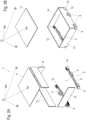
- the drawer device 4 further comprises a base 11, two side walls 12, a front panel 13 and a rear wall 14, which are plate-shaped and consist, for example, of a transparent material, in particular plastic. It is also possible to make only the front panel 13 transparent, so that the contents of the drawer device 4 are visible when the door 3 is opened. Other materials such as glass, wood or composite materials for the front panel 13, rear wall 14 or the side walls 12 are also conceivable, whereby different materials can also be combined in a drawer device.
- the ends of a side wall 12 are inserted into a receptacle that is open at the top on a rear holder 10 and a front holder 9.
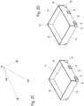
- the two front holders 9 are connected to one another via the front panel 13 and the two rear holders 10 via the rear wall 14, preferably by inserting the front panel 13 and the rear wall 14 from above (see Fig. 2B ).
- the base 11 is placed on the two front holders 9 and the two rear holders 10 on a support so that the Figure 2C shown position is obtained.
- the drawer 4 comprises a box-shaped receptacle and objects can be placed on the floor 11.
- the front panel 13 and the rear wall 14 can be mounted, which are angled and are plugged from above onto a corner area between the side walls and the rear wall or the side walls and the front panel 13.
- the drawer thus formed can be manufactured with just a few components and assembly steps.
- the height and material of the side walls 12, the rear wall 14 and the front panel 13 can be selected flexibly.
- one of the two pull-out guides 5 is shown with the front holder 9 and the rear holder 10.
- the other pull-out guide 5 is designed in a mirror image and is fixed to the opposite side wall of the body 2.
- the pull-out guide 5 comprises the stationary guide rail 6, the movable guide rail 7 and a pull-out-extending middle rail 60 arranged between the guide rail 6 and the guide rail 7.
- the front holder 9 and the rear holder 10 each form a support 16 which is formed by a rib structure, a plate or another shape and serves to support a corner area of the base 11.
- a surface of the Support 16 can also be rubberized or provided with an elastic material to make it more difficult for the base 11 to move.
- the rear holder 10 comprises a groove-shaped receptacle 17 which extends longitudinally parallel to the guide rail 7 and serves to receive a lower, rear end of a side wall 12.
- a further groove-shaped receptacle 18 is arranged at an angle to this and serves to insert one end of a rear wall 14.
- the depths of the groove-shaped receptacles 17 and 18 can be different; in particular, the groove-shaped receptacle 17 for the side wall 12 can be deeper than the groove-shaped receptacle 18 for receiving the rear wall 14.
- the respective outer groove walls on the groove-shaped receptacle 17 and the groove-shaped receptacle 18 are higher than the shelf 16 and can thus limit pivoting of the side wall 12 and the rear wall 14 and optionally also limit displacement of the base 11 in the horizontal direction when the holders 9 and 10 are mounted without side walls 12, front panel 13 and rear wall 14.
- the front holder 9 comprises a groove-shaped receptacle 19 which extends substantially perpendicular to the longitudinal direction of the guide rail 7 and serves for inserting one end of the front panel 13.
- a further groove-shaped receptacle 17 for inserting a front end of the side wall 12 is also formed on the front holder 9.
- a self-closing mechanism 20 is also provided on the pull-out guide 5 in the area of the front holder 9, which comprises a housing 21 attached to the guide rail 6, on which a movable driver 22 can be moved along a guide track.
- the driver 22 is preloaded into a closed position via a spring and optionally also a damper within a cartridge 23.
- the driver 22 engages with a projection 24 which is integrally formed with the holder 9, but can also be attached to it via fastening means.
- the guide rail 7 moves in the opening direction, the driver 22 is moved along the guide track until it pivots and thereby releases the projection 24, so that the guide rail 7 can be moved independently of the self-closing mechanism 20.
- FIG 4 the rear holder 10 is shown in a dismantled position. It can be seen that an upwardly protruding hook 70 is formed on the guide rail 7, which serves to fix the rear holder 10.
- the rear holder 10 is shown in detail.
- the hook 70 protruding upwards engages over a web 71 of the rear holder 10, so that the latter is fixed via the hook 70 in a clamping or form-fitting manner between an upper side of the guide rail 7 and the hook 70.
- the hook 70 is also accommodated between two webs 72, which limit a lateral movement of the holder 10 perpendicular to the longitudinal direction of the guide rail 7. This allows the holder 10 to be pushed backwards onto the hook 70 on the guide rail 7.
- the front holder 9 and its assembly are shown.
- the front holder 9 is fixed at a front end to the guide rail 7 and comprises a plug 30 which is inserted into a hollow chamber of the guide rail 7.
- the plug 30 can be fixed in a clamped or form-fitting manner via a web 31 in order to make it more difficult to dismantle the holder 9.
- the front holder 9 can also be fixed to the guide rail 7 via a screw 32.
- the projection 24 is shown with an angled web-shaped activator 25, which engages in a receptacle on the driver 22 and is thus movable together with it:
- the driver 22 is movable along a guide track 26 on the housing 21 of the self-retractor 20.
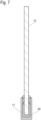
- Figure 7 a section through a side wall 12 is shown, which is fixed to a groove-shaped receptacle 17.
- the width of the groove-shaped receptacle 17 can be approximately the same size as the thickness of the side wall 12; optionally, it is also possible to insert an elastic element 40 into the groove-shaped receptacle 17, which engages around a lower edge of the side wall 12 in a U-shape.
- the side wall 12 can thus be fixed in the groove-shaped receptacle 17 by clamping.
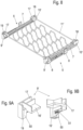
- FIG 8 a modified sliding device is shown, in which two pull-out guides 5 are provided, which are designed essentially as in the previous embodiment and on each of which a front holder 9' and a rear holder 10' are fixed to the movable guide rail 7.
- the sliding device comprises a modified base 11', which is not plate-shaped, but rather as a grid, for example for placing wine bottles or for storing other objects.
- This modified base 11' rests in the corner area on one of the holders 9' and 10'. and is secured against horizontal displacement by the holders 9' and 10'.
- a front holder 9' is shown, whereby the rear holder 10' can optionally be of identical design.
- the front holder 9' comprises a groove-shaped receptacle 19 for fixing a front panel and a further groove-shaped receptacle 17 aligned at an angle thereto for inserting a side wall 12.
- a horizontal support 16' is provided on the holder 9' for supporting a corner area of the base 11'.
- the support 16' is arranged somewhat lower so that the walls of the groove-shaped receptacles 17 and 19 are arranged higher than the support 16' and thus limit displacement of the base 11' in the horizontal plane.
- the front holder 9' further comprises a downwardly projecting fastening part 50 on which fastening means 51 are mounted in order to fix the holder 9' to the guide rail 7.
- the holders 9, 9', 10, 10' are made as molded parts made of plastic, which can optionally also comprise two different plastic materials.
- the fastening of the holders 9, 9', 10, 10' to the movable guide rail 7 can be varied.
- the front holder 9 can also be fixed to the guide rail 7 via a hook 70 or the rear holder 10 is mounted via a plug that is inserted into a hollow chamber of the guide rail 7.
- the design of the base 11 and 11' can be varied, depending on which objects are to be stored on the push device 4.
- the supports 16 and 16' on the holders 9, 9', 10, 10' can be arranged both above the upper side of the guide rail 7 and on an inner side of the guide rail 7 and below the upper side.
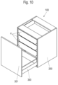
- Figure 10 1 shows an example of a piece of furniture 100 or household appliance with a body 200 and a drawer 300 with a high front panel 301.
- a drawer 300 with a high front panel 301.
- several pull-out devices 4 according to the invention are mounted in an extendable manner, which are designed, for example, as internal drawers.
Landscapes
- Engineering & Computer Science (AREA)
- Chemical & Material Sciences (AREA)
- Combustion & Propulsion (AREA)
- Physics & Mathematics (AREA)
- Mechanical Engineering (AREA)
- Thermal Sciences (AREA)
- General Engineering & Computer Science (AREA)
- Drawers Of Furniture (AREA)
Applications Claiming Priority (2)
| Application Number | Priority Date | Filing Date | Title |
|---|---|---|---|
| DE102020127746.6A DE102020127746A1 (de) | 2020-10-21 | 2020-10-21 | Schubvorrichtung und Verfahren zur Montage einer Schubvorrichtung |
| PCT/EP2021/077354 WO2022084020A1 (de) | 2020-10-21 | 2021-10-05 | Schubvorrichtung und verfahren zur montage einer schubvorrichtung |
Publications (2)
| Publication Number | Publication Date |
|---|---|
| EP4231875A1 EP4231875A1 (de) | 2023-08-30 |
| EP4231875B1 true EP4231875B1 (de) | 2024-07-31 |
Family
ID=78086346
Family Applications (1)
| Application Number | Title | Priority Date | Filing Date |
|---|---|---|---|
| EP21790107.3A Active EP4231875B1 (de) | 2020-10-21 | 2021-10-05 | Schubvorrichtung und verfahren zur montage einer schubvorrichtung |
Country Status (9)
| Country | Link |
|---|---|
| US (1) | US20230380591A1 (pl) |
| EP (1) | EP4231875B1 (pl) |
| JP (1) | JP7791186B2 (pl) |
| KR (1) | KR20230086786A (pl) |
| CN (1) | CN116507245B (pl) |
| DE (1) | DE102020127746A1 (pl) |
| ES (1) | ES2989349T3 (pl) |
| PL (1) | PL4231875T3 (pl) |
| WO (1) | WO2022084020A1 (pl) |
Family Cites Families (27)
| Publication number | Priority date | Publication date | Assignee | Title |
|---|---|---|---|---|
| US3998509A (en) * | 1975-07-28 | 1976-12-21 | Hauser Jon W | Case and corner fastener therefor |
| DE8431503U1 (de) * | 1984-10-26 | 1985-01-31 | Paul Hettich GmbH & Co, 4983 Kirchlengern | Schubkasten |
| DE8716434U1 (de) * | 1987-12-12 | 1988-02-04 | Ziehl, Gustav, 5000 Köln | Stahlschubkasten |
| DE4032426C2 (de) * | 1990-10-12 | 1999-04-08 | Lautenschlaeger Mepla Werke | Halterungsbeschlag für Schubladen-Ausziehführungen |
| JPH07197918A (ja) * | 1994-01-05 | 1995-08-01 | Hiroe Tsunoda | 組立機構、その組立機構により組み立てた構造物、その構造物に使用する引き出し。 |
| US5632542A (en) * | 1995-06-07 | 1997-05-27 | Snap-On Technologies, Inc. | Drawer slide interlock apparatus |
| DE19944638A1 (de) * | 1999-09-17 | 2001-03-22 | Hettich Paul Gmbh & Co | Befestigungsanordnung |
| DE20108388U1 (de) * | 2001-05-18 | 2002-09-26 | Vauth-Sagel GmbH & Co. Grundstücksverwaltung, 33034 Brakel | Korbträger eines Auszugsbeschlages |
| US7810890B2 (en) * | 2006-10-13 | 2010-10-12 | Lynk, Inc. | Glide mechanism for roll out drawers and other items |
| AU2007234507B2 (en) * | 2006-12-15 | 2013-09-12 | Harn Marketing Sdn. Bhd. | Corner fitting |
| TWM318676U (en) * | 2007-03-19 | 2007-09-11 | Four Winds Corp | Improved rack structure |
| DE202008003328U1 (de) | 2007-10-02 | 2009-02-12 | Paul Hettich Gmbh & Co. Kg | Auszugsführung mit einer Selbsteinzugsvorrichtung |
| SI22602A (sl) * | 2007-10-30 | 2009-04-30 | Gorenje Gospodinjski Aparati, D.D. | Sklop predala in kolesnih izvlečnih vodil zanj |
| DE202008011114U1 (de) | 2008-08-21 | 2010-01-07 | Paul Hettich Gmbh & Co. Kg | Ausziehführung für Schubkästen mit einem Fanghaken |
| AT11720U3 (de) | 2010-09-16 | 2011-12-15 | Mediadent Medizinisch Tech Produktions Und Vertriebs Gmbh | Adapter für ein ladensystem |
| DE102011052564A1 (de) * | 2011-05-17 | 2012-11-22 | Paul Hettich Gmbh & Co. Kg | Verschiebbares Möbelteil und Möbel |
| CN102954656B (zh) * | 2011-08-27 | 2016-09-28 | 博西华电器(江苏)有限公司 | 家用电器 |
| CN103054359A (zh) * | 2012-12-31 | 2013-04-24 | 黄宇 | 一种隐藏式抽屉滑轨 |
| DE202013100013U1 (de) * | 2013-01-02 | 2013-01-22 | Nan Juen International Co., Ltd. | Schnellverbindungsanordnung für eine Gleitschiene |
| DE202013003342U1 (de) * | 2013-04-10 | 2013-06-06 | Kesseböhmer Holding e.K. | Auszugsvorrichtung für Möbel |
| US20150208801A1 (en) | 2014-01-26 | 2015-07-30 | Yajun Hu | Slidable storage container and sliding mechanism |
| DE102014104136A1 (de) * | 2014-03-25 | 2015-10-01 | Paul Hettich Gmbh & Co. Kg | Auszugsführung für einen Schubkasten und Verfahren zur Befestigung eines Schubkastens an einer Auszugsführung |
| KR101639135B1 (ko) * | 2014-11-28 | 2016-07-12 | 엘지전자 주식회사 | 수납 박스 어셈블리 및 이를 구비한 냉장고 |
| AT520636B1 (de) * | 2018-01-26 | 2019-06-15 | Blum Gmbh Julius | Frontblende für eine Schublade |
| CN209235361U (zh) * | 2018-11-09 | 2019-08-13 | 江门市新会区二轻机械厂有限公司 | 一种带静音抽屉的金属储物柜 |
| CN209893786U (zh) * | 2019-03-12 | 2020-01-03 | 青岛海尔电冰箱有限公司 | 冰箱 |
| KR102314062B1 (ko) * | 2019-07-02 | 2021-10-19 | (주)문주하드웨어 | 서랍용 언더레일 가이드 브라켓 |
-
2020
- 2020-10-21 DE DE102020127746.6A patent/DE102020127746A1/de active Pending
-
2021
- 2021-10-05 ES ES21790107T patent/ES2989349T3/es active Active
- 2021-10-05 US US18/031,702 patent/US20230380591A1/en not_active Abandoned
- 2021-10-05 KR KR1020237016775A patent/KR20230086786A/ko active Pending
- 2021-10-05 PL PL21790107.3T patent/PL4231875T3/pl unknown
- 2021-10-05 EP EP21790107.3A patent/EP4231875B1/de active Active
- 2021-10-05 WO PCT/EP2021/077354 patent/WO2022084020A1/de not_active Ceased
- 2021-10-05 JP JP2023524417A patent/JP7791186B2/ja active Active
- 2021-10-05 CN CN202180068121.8A patent/CN116507245B/zh active Active
Also Published As
| Publication number | Publication date |
|---|---|
| CN116507245B (zh) | 2025-11-11 |
| WO2022084020A1 (de) | 2022-04-28 |
| CN116507245A (zh) | 2023-07-28 |
| KR20230086786A (ko) | 2023-06-15 |
| EP4231875A1 (de) | 2023-08-30 |
| JP2023546239A (ja) | 2023-11-01 |
| DE102020127746A1 (de) | 2022-04-21 |
| ES2989349T3 (es) | 2024-11-26 |
| JP7791186B2 (ja) | 2025-12-23 |
| US20230380591A1 (en) | 2023-11-30 |
| PL4231875T3 (pl) | 2024-12-16 |
Similar Documents
| Publication | Publication Date | Title |
|---|---|---|
| EP3817625B1 (de) | Ablageboden für ein möbel oder haushaltsgerät | |
| EP1084661B1 (de) | Unterteilungssystem | |
| EP2499445B1 (de) | Kältegerät mit einem türabsteller und einer schwimmend gelagerten rastvorrichtung | |
| EP2220446B1 (de) | Kältegerät | |
| EP2160555B1 (de) | Haushalts-kältegerät mit einbauteil | |
| DE19511639C1 (de) | Schaltschrank mit Rahmengestell und Montageplatte | |
| EP3758553B1 (de) | Möbel oder haushaltsgerät und verfahren zur montage einer funktionseinheit eines schubelements in einem möbel oder haushaltsgerät | |
| DE102017205089A1 (de) | Haushaltskältegerät mit einer Innenverkleidung mit mehreren separaten Verkleidungswänden sowie Verfahren zum Herstellen eines Haushaltskältegeräts | |
| EP3775727B1 (de) | Haushaltsgerät mit einer wand, die ein integriertes, erhabenes koppelelement zum koppeln mit einem daran angeordneten hinterlegteil aufweist, sowie verfahren zur montage des koppelelements an der wand | |
| EP4231875B1 (de) | Schubvorrichtung und verfahren zur montage einer schubvorrichtung | |
| DE4226601A1 (de) | Tragteil für in den Innenraum eines Möbels einbringbare Zwischenböden | |
| EP0582784B1 (de) | Kühlmöbel mit Tragteilen zur Abstützung von Ablagen | |
| DE102012001374B4 (de) | Kühl- und/oder Gefriergerät | |
| DE102019208449A1 (de) | Lebensmittel-Aufnahmebehälter mit einer auf unterschiedlichen Höhenlagen in verschiedenen Raumrichtungen gehaltenen Trennwand, sowie Verfahren zur Montage einer Trennwand | |
| AT522739B1 (de) | Innenschubkasten und Möbel oder Haushaltsgerät | |
| EP1746373B1 (de) | Kühl- und/oder Gefriergeräte | |
| DE102021207031A1 (de) | Ablageplattenanordnung zum Einbau in ein Haushaltskältegerät und Haushaltskältegerät | |
| DE4327688A1 (de) | Auszugführung | |
| DE19907186A1 (de) | Halteelement | |
| AT525499B1 (de) | Schubsystem | |
| DE19821898C1 (de) | Regalsystem | |
| DE102021210182A1 (de) | Haushaltskältegerät mit schräg zur Horizontalen angeordnetem Hinterlegteil | |
| DE102024101349A1 (de) | Möbelelement | |
| EP4116653A1 (de) | Ablageplattenanordnung zum einbau in ein haushaltskältegerät | |
| DE102012222641A1 (de) | Kältegerät mit Schwenkladenvorrichtung |
Legal Events
| Date | Code | Title | Description |
|---|---|---|---|
| STAA | Information on the status of an ep patent application or granted ep patent |
Free format text: STATUS: UNKNOWN |
|
| STAA | Information on the status of an ep patent application or granted ep patent |
Free format text: STATUS: THE INTERNATIONAL PUBLICATION HAS BEEN MADE |
|
| PUAI | Public reference made under article 153(3) epc to a published international application that has entered the european phase |
Free format text: ORIGINAL CODE: 0009012 |
|
| STAA | Information on the status of an ep patent application or granted ep patent |
Free format text: STATUS: REQUEST FOR EXAMINATION WAS MADE |
|
| 17P | Request for examination filed |
Effective date: 20230505 |
|
| AK | Designated contracting states |
Kind code of ref document: A1 Designated state(s): AL AT BE BG CH CY CZ DE DK EE ES FI FR GB GR HR HU IE IS IT LI LT LU LV MC MK MT NL NO PL PT RO RS SE SI SK SM TR |
|
| DAV | Request for validation of the european patent (deleted) | ||
| DAX | Request for extension of the european patent (deleted) | ||
| GRAP | Despatch of communication of intention to grant a patent |
Free format text: ORIGINAL CODE: EPIDOSNIGR1 |
|
| STAA | Information on the status of an ep patent application or granted ep patent |
Free format text: STATUS: GRANT OF PATENT IS INTENDED |
|
| INTG | Intention to grant announced |
Effective date: 20240320 |
|
| RAP3 | Party data changed (applicant data changed or rights of an application transferred) |
Owner name: PAUL HETTICH GMBH & CO. KG |
|
| GRAS | Grant fee paid |
Free format text: ORIGINAL CODE: EPIDOSNIGR3 |
|
| GRAA | (expected) grant |
Free format text: ORIGINAL CODE: 0009210 |
|
| STAA | Information on the status of an ep patent application or granted ep patent |
Free format text: STATUS: THE PATENT HAS BEEN GRANTED |
|
| P01 | Opt-out of the competence of the unified patent court (upc) registered |
Effective date: 20240529 |
|
| AK | Designated contracting states |
Kind code of ref document: B1 Designated state(s): AL AT BE BG CH CY CZ DE DK EE ES FI FR GB GR HR HU IE IS IT LI LT LU LV MC MK MT NL NO PL PT RO RS SE SI SK SM TR |
|
| REG | Reference to a national code |
Ref country code: CH Ref legal event code: EP Ref country code: GB Ref legal event code: FG4D Free format text: NOT ENGLISH |
|
| REG | Reference to a national code |
Ref country code: DE Ref legal event code: R096 Ref document number: 502021004619 Country of ref document: DE |
|
| REG | Reference to a national code |
Ref country code: IE Ref legal event code: FG4D Free format text: LANGUAGE OF EP DOCUMENT: GERMAN |
|
| REG | Reference to a national code |
Ref country code: DE Ref legal event code: R084 Ref document number: 502021004619 Country of ref document: DE |
|
| REG | Reference to a national code |
Ref country code: ES Ref legal event code: GC2A Effective date: 20241023 |
|
| REG | Reference to a national code |
Ref country code: LT Ref legal event code: MG9D |
|
| REG | Reference to a national code |
Ref country code: ES Ref legal event code: FG2A Ref document number: 2989349 Country of ref document: ES Kind code of ref document: T3 Effective date: 20241126 |
|
| REG | Reference to a national code |
Ref country code: NL Ref legal event code: MP Effective date: 20240731 |
|
| PG25 | Lapsed in a contracting state [announced via postgrant information from national office to epo] |
Ref country code: PT Free format text: LAPSE BECAUSE OF FAILURE TO SUBMIT A TRANSLATION OF THE DESCRIPTION OR TO PAY THE FEE WITHIN THE PRESCRIBED TIME-LIMIT Effective date: 20241202 |
|
| PG25 | Lapsed in a contracting state [announced via postgrant information from national office to epo] |
Ref country code: PT Free format text: LAPSE BECAUSE OF FAILURE TO SUBMIT A TRANSLATION OF THE DESCRIPTION OR TO PAY THE FEE WITHIN THE PRESCRIBED TIME-LIMIT Effective date: 20241202 |
|
| PG25 | Lapsed in a contracting state [announced via postgrant information from national office to epo] |
Ref country code: NO Free format text: LAPSE BECAUSE OF FAILURE TO SUBMIT A TRANSLATION OF THE DESCRIPTION OR TO PAY THE FEE WITHIN THE PRESCRIBED TIME-LIMIT Effective date: 20241031 |
|
| PG25 | Lapsed in a contracting state [announced via postgrant information from national office to epo] |
Ref country code: FI Free format text: LAPSE BECAUSE OF FAILURE TO SUBMIT A TRANSLATION OF THE DESCRIPTION OR TO PAY THE FEE WITHIN THE PRESCRIBED TIME-LIMIT Effective date: 20240731 Ref country code: GR Free format text: LAPSE BECAUSE OF FAILURE TO SUBMIT A TRANSLATION OF THE DESCRIPTION OR TO PAY THE FEE WITHIN THE PRESCRIBED TIME-LIMIT Effective date: 20241101 Ref country code: NL Free format text: LAPSE BECAUSE OF FAILURE TO SUBMIT A TRANSLATION OF THE DESCRIPTION OR TO PAY THE FEE WITHIN THE PRESCRIBED TIME-LIMIT Effective date: 20240731 |
|
| PG25 | Lapsed in a contracting state [announced via postgrant information from national office to epo] |
Ref country code: BG Free format text: LAPSE BECAUSE OF FAILURE TO SUBMIT A TRANSLATION OF THE DESCRIPTION OR TO PAY THE FEE WITHIN THE PRESCRIBED TIME-LIMIT Effective date: 20240731 |
|
| PG25 | Lapsed in a contracting state [announced via postgrant information from national office to epo] |
Ref country code: LV Free format text: LAPSE BECAUSE OF FAILURE TO SUBMIT A TRANSLATION OF THE DESCRIPTION OR TO PAY THE FEE WITHIN THE PRESCRIBED TIME-LIMIT Effective date: 20240731 |
|
| PG25 | Lapsed in a contracting state [announced via postgrant information from national office to epo] |
Ref country code: IS Free format text: LAPSE BECAUSE OF FAILURE TO SUBMIT A TRANSLATION OF THE DESCRIPTION OR TO PAY THE FEE WITHIN THE PRESCRIBED TIME-LIMIT Effective date: 20241130 |
|
| PG25 | Lapsed in a contracting state [announced via postgrant information from national office to epo] |
Ref country code: HR Free format text: LAPSE BECAUSE OF FAILURE TO SUBMIT A TRANSLATION OF THE DESCRIPTION OR TO PAY THE FEE WITHIN THE PRESCRIBED TIME-LIMIT Effective date: 20240731 |
|
| PG25 | Lapsed in a contracting state [announced via postgrant information from national office to epo] |
Ref country code: RS Free format text: LAPSE BECAUSE OF FAILURE TO SUBMIT A TRANSLATION OF THE DESCRIPTION OR TO PAY THE FEE WITHIN THE PRESCRIBED TIME-LIMIT Effective date: 20241031 |
|
| PG25 | Lapsed in a contracting state [announced via postgrant information from national office to epo] |
Ref country code: RS Free format text: LAPSE BECAUSE OF FAILURE TO SUBMIT A TRANSLATION OF THE DESCRIPTION OR TO PAY THE FEE WITHIN THE PRESCRIBED TIME-LIMIT Effective date: 20241031 Ref country code: NO Free format text: LAPSE BECAUSE OF FAILURE TO SUBMIT A TRANSLATION OF THE DESCRIPTION OR TO PAY THE FEE WITHIN THE PRESCRIBED TIME-LIMIT Effective date: 20241031 Ref country code: NL Free format text: LAPSE BECAUSE OF FAILURE TO SUBMIT A TRANSLATION OF THE DESCRIPTION OR TO PAY THE FEE WITHIN THE PRESCRIBED TIME-LIMIT Effective date: 20240731 Ref country code: LV Free format text: LAPSE BECAUSE OF FAILURE TO SUBMIT A TRANSLATION OF THE DESCRIPTION OR TO PAY THE FEE WITHIN THE PRESCRIBED TIME-LIMIT Effective date: 20240731 Ref country code: IS Free format text: LAPSE BECAUSE OF FAILURE TO SUBMIT A TRANSLATION OF THE DESCRIPTION OR TO PAY THE FEE WITHIN THE PRESCRIBED TIME-LIMIT Effective date: 20241130 Ref country code: HR Free format text: LAPSE BECAUSE OF FAILURE TO SUBMIT A TRANSLATION OF THE DESCRIPTION OR TO PAY THE FEE WITHIN THE PRESCRIBED TIME-LIMIT Effective date: 20240731 Ref country code: GR Free format text: LAPSE BECAUSE OF FAILURE TO SUBMIT A TRANSLATION OF THE DESCRIPTION OR TO PAY THE FEE WITHIN THE PRESCRIBED TIME-LIMIT Effective date: 20241101 Ref country code: FI Free format text: LAPSE BECAUSE OF FAILURE TO SUBMIT A TRANSLATION OF THE DESCRIPTION OR TO PAY THE FEE WITHIN THE PRESCRIBED TIME-LIMIT Effective date: 20240731 Ref country code: BG Free format text: LAPSE BECAUSE OF FAILURE TO SUBMIT A TRANSLATION OF THE DESCRIPTION OR TO PAY THE FEE WITHIN THE PRESCRIBED TIME-LIMIT Effective date: 20240731 |
|
| PGFP | Annual fee paid to national office [announced via postgrant information from national office to epo] |
Ref country code: TR Payment date: 20241024 Year of fee payment: 4 |
|
| PG25 | Lapsed in a contracting state [announced via postgrant information from national office to epo] |
Ref country code: RO Free format text: LAPSE BECAUSE OF FAILURE TO SUBMIT A TRANSLATION OF THE DESCRIPTION OR TO PAY THE FEE WITHIN THE PRESCRIBED TIME-LIMIT Effective date: 20240731 Ref country code: SM Free format text: LAPSE BECAUSE OF FAILURE TO SUBMIT A TRANSLATION OF THE DESCRIPTION OR TO PAY THE FEE WITHIN THE PRESCRIBED TIME-LIMIT Effective date: 20240731 Ref country code: DK Free format text: LAPSE BECAUSE OF FAILURE TO SUBMIT A TRANSLATION OF THE DESCRIPTION OR TO PAY THE FEE WITHIN THE PRESCRIBED TIME-LIMIT Effective date: 20240731 |
|
| PG25 | Lapsed in a contracting state [announced via postgrant information from national office to epo] |
Ref country code: EE Free format text: LAPSE BECAUSE OF FAILURE TO SUBMIT A TRANSLATION OF THE DESCRIPTION OR TO PAY THE FEE WITHIN THE PRESCRIBED TIME-LIMIT Effective date: 20240731 |
|
| PG25 | Lapsed in a contracting state [announced via postgrant information from national office to epo] |
Ref country code: CZ Free format text: LAPSE BECAUSE OF FAILURE TO SUBMIT A TRANSLATION OF THE DESCRIPTION OR TO PAY THE FEE WITHIN THE PRESCRIBED TIME-LIMIT Effective date: 20240731 |
|
| PG25 | Lapsed in a contracting state [announced via postgrant information from national office to epo] |
Ref country code: SK Free format text: LAPSE BECAUSE OF FAILURE TO SUBMIT A TRANSLATION OF THE DESCRIPTION OR TO PAY THE FEE WITHIN THE PRESCRIBED TIME-LIMIT Effective date: 20240731 |
|
| REG | Reference to a national code |
Ref country code: DE Ref legal event code: R097 Ref document number: 502021004619 Country of ref document: DE |
|
| REG | Reference to a national code |
Ref country code: CH Ref legal event code: PL |
|
| PLBE | No opposition filed within time limit |
Free format text: ORIGINAL CODE: 0009261 |
|
| STAA | Information on the status of an ep patent application or granted ep patent |
Free format text: STATUS: NO OPPOSITION FILED WITHIN TIME LIMIT |
|
| PG25 | Lapsed in a contracting state [announced via postgrant information from national office to epo] |
Ref country code: MC Free format text: LAPSE BECAUSE OF FAILURE TO SUBMIT A TRANSLATION OF THE DESCRIPTION OR TO PAY THE FEE WITHIN THE PRESCRIBED TIME-LIMIT Effective date: 20240731 |
|
| 26N | No opposition filed |
Effective date: 20250501 |
|
| PG25 | Lapsed in a contracting state [announced via postgrant information from national office to epo] |
Ref country code: LU Free format text: LAPSE BECAUSE OF NON-PAYMENT OF DUE FEES Effective date: 20241005 Ref country code: BE Free format text: LAPSE BECAUSE OF NON-PAYMENT OF DUE FEES Effective date: 20241031 |
|
| PG25 | Lapsed in a contracting state [announced via postgrant information from national office to epo] |
Ref country code: FR Free format text: LAPSE BECAUSE OF NON-PAYMENT OF DUE FEES Effective date: 20241031 |
|
| PG25 | Lapsed in a contracting state [announced via postgrant information from national office to epo] |
Ref country code: CH Free format text: LAPSE BECAUSE OF NON-PAYMENT OF DUE FEES Effective date: 20241031 |
|
| REG | Reference to a national code |
Ref country code: BE Ref legal event code: MM Effective date: 20241031 |
|
| PG25 | Lapsed in a contracting state [announced via postgrant information from national office to epo] |
Ref country code: SE Free format text: LAPSE BECAUSE OF FAILURE TO SUBMIT A TRANSLATION OF THE DESCRIPTION OR TO PAY THE FEE WITHIN THE PRESCRIBED TIME-LIMIT Effective date: 20240731 |
|
| PGFP | Annual fee paid to national office [announced via postgrant information from national office to epo] |
Ref country code: PL Payment date: 20250919 Year of fee payment: 5 |
|
| PG25 | Lapsed in a contracting state [announced via postgrant information from national office to epo] |
Ref country code: IE Free format text: LAPSE BECAUSE OF NON-PAYMENT OF DUE FEES Effective date: 20241005 |
|
| PGFP | Annual fee paid to national office [announced via postgrant information from national office to epo] |
Ref country code: DE Payment date: 20251020 Year of fee payment: 5 |
|
| PGFP | Annual fee paid to national office [announced via postgrant information from national office to epo] |
Ref country code: AT Payment date: 20260113 Year of fee payment: 5 |
|
| PGFP | Annual fee paid to national office [announced via postgrant information from national office to epo] |
Ref country code: IT Payment date: 20251031 Year of fee payment: 5 |
|
| PG25 | Lapsed in a contracting state [announced via postgrant information from national office to epo] |
Ref country code: CY Free format text: LAPSE BECAUSE OF FAILURE TO SUBMIT A TRANSLATION OF THE DESCRIPTION OR TO PAY THE FEE WITHIN THE PRESCRIBED TIME-LIMIT; INVALID AB INITIO Effective date: 20211005 |
|
| PGFP | Annual fee paid to national office [announced via postgrant information from national office to epo] |
Ref country code: ES Payment date: 20251114 Year of fee payment: 5 |
|
| PG25 | Lapsed in a contracting state [announced via postgrant information from national office to epo] |
Ref country code: HU Free format text: LAPSE BECAUSE OF FAILURE TO SUBMIT A TRANSLATION OF THE DESCRIPTION OR TO PAY THE FEE WITHIN THE PRESCRIBED TIME-LIMIT; INVALID AB INITIO Effective date: 20211005 |