EP4185534B1 - Deckel zum verschliessen eines behälters sowie system aus einem behälter und einem deckel - Google Patents
Deckel zum verschliessen eines behälters sowie system aus einem behälter und einem deckel Download PDFInfo
- Publication number
- EP4185534B1 EP4185534B1 EP21740552.1A EP21740552A EP4185534B1 EP 4185534 B1 EP4185534 B1 EP 4185534B1 EP 21740552 A EP21740552 A EP 21740552A EP 4185534 B1 EP4185534 B1 EP 4185534B1
- Authority
- EP
- European Patent Office
- Prior art keywords
- cover
- container
- connector
- lid
- movable
- Prior art date
- Legal status (The legal status is an assumption and is not a legal conclusion. Google has not performed a legal analysis and makes no representation as to the accuracy of the status listed.)
- Active
Links
Images


Classifications
-
- B—PERFORMING OPERATIONS; TRANSPORTING
- B65—CONVEYING; PACKING; STORING; HANDLING THIN OR FILAMENTARY MATERIAL
- B65D—CONTAINERS FOR STORAGE OR TRANSPORT OF ARTICLES OR MATERIALS, e.g. BAGS, BARRELS, BOTTLES, BOXES, CANS, CARTONS, CRATES, DRUMS, JARS, TANKS, HOPPERS, FORWARDING CONTAINERS; ACCESSORIES, CLOSURES, OR FITTINGS THEREFOR; PACKAGING ELEMENTS; PACKAGES
- B65D1/00—Rigid or semi-rigid containers having bodies formed in one piece, e.g. by casting metallic material, by moulding plastics, by blowing vitreous material, by throwing ceramic material, by moulding pulped fibrous material or by deep-drawing operations performed on sheet material
- B65D1/22—Boxes or like containers with side walls of substantial depth for enclosing contents
- B65D1/24—Boxes or like containers with side walls of substantial depth for enclosing contents with moulded compartments or partitions
- B65D1/243—Crates for bottles or like containers
- B65D1/246—Cover elements inserted in crates
-
- B—PERFORMING OPERATIONS; TRANSPORTING
- B65—CONVEYING; PACKING; STORING; HANDLING THIN OR FILAMENTARY MATERIAL
- B65D—CONTAINERS FOR STORAGE OR TRANSPORT OF ARTICLES OR MATERIALS, e.g. BAGS, BARRELS, BOTTLES, BOXES, CANS, CARTONS, CRATES, DRUMS, JARS, TANKS, HOPPERS, FORWARDING CONTAINERS; ACCESSORIES, CLOSURES, OR FITTINGS THEREFOR; PACKAGING ELEMENTS; PACKAGES
- B65D55/00—Accessories for container closures not otherwise provided for
- B65D55/02—Locking devices; Means for discouraging or indicating unauthorised opening or removal of closure
-
- B—PERFORMING OPERATIONS; TRANSPORTING
- B65—CONVEYING; PACKING; STORING; HANDLING THIN OR FILAMENTARY MATERIAL
- B65D—CONTAINERS FOR STORAGE OR TRANSPORT OF ARTICLES OR MATERIALS, e.g. BAGS, BARRELS, BOTTLES, BOXES, CANS, CARTONS, CRATES, DRUMS, JARS, TANKS, HOPPERS, FORWARDING CONTAINERS; ACCESSORIES, CLOSURES, OR FITTINGS THEREFOR; PACKAGING ELEMENTS; PACKAGES
- B65D43/00—Lids or covers for rigid or semi-rigid containers
- B65D43/02—Removable lids or covers
- B65D43/0202—Removable lids or covers without integral tamper element
-
- B—PERFORMING OPERATIONS; TRANSPORTING
- B65—CONVEYING; PACKING; STORING; HANDLING THIN OR FILAMENTARY MATERIAL
- B65D—CONTAINERS FOR STORAGE OR TRANSPORT OF ARTICLES OR MATERIALS, e.g. BAGS, BARRELS, BOTTLES, BOXES, CANS, CARTONS, CRATES, DRUMS, JARS, TANKS, HOPPERS, FORWARDING CONTAINERS; ACCESSORIES, CLOSURES, OR FITTINGS THEREFOR; PACKAGING ELEMENTS; PACKAGES
- B65D55/00—Accessories for container closures not otherwise provided for
- B65D55/02—Locking devices; Means for discouraging or indicating unauthorised opening or removal of closure
- B65D55/12—Devices or means with relatively-moving parts co-operating with abutments on bottle or jar
-
- B—PERFORMING OPERATIONS; TRANSPORTING
- B65—CONVEYING; PACKING; STORING; HANDLING THIN OR FILAMENTARY MATERIAL
- B65D—CONTAINERS FOR STORAGE OR TRANSPORT OF ARTICLES OR MATERIALS, e.g. BAGS, BARRELS, BOTTLES, BOXES, CANS, CARTONS, CRATES, DRUMS, JARS, TANKS, HOPPERS, FORWARDING CONTAINERS; ACCESSORIES, CLOSURES, OR FITTINGS THEREFOR; PACKAGING ELEMENTS; PACKAGES
- B65D1/00—Rigid or semi-rigid containers having bodies formed in one piece, e.g. by casting metallic material, by moulding plastics, by blowing vitreous material, by throwing ceramic material, by moulding pulped fibrous material or by deep-drawing operations performed on sheet material
- B65D1/22—Boxes or like containers with side walls of substantial depth for enclosing contents
-
- B—PERFORMING OPERATIONS; TRANSPORTING
- B65—CONVEYING; PACKING; STORING; HANDLING THIN OR FILAMENTARY MATERIAL
- B65D—CONTAINERS FOR STORAGE OR TRANSPORT OF ARTICLES OR MATERIALS, e.g. BAGS, BARRELS, BOTTLES, BOXES, CANS, CARTONS, CRATES, DRUMS, JARS, TANKS, HOPPERS, FORWARDING CONTAINERS; ACCESSORIES, CLOSURES, OR FITTINGS THEREFOR; PACKAGING ELEMENTS; PACKAGES
- B65D2543/00—Lids or covers essentially for box-like containers
- B65D2543/00009—Details of lids or covers for rigid or semi-rigid containers
- B65D2543/00018—Overall construction of the lid
- B65D2543/00064—Shape of the outer periphery
- B65D2543/0012—Shape of the outer periphery having straight sides, e.g. with curved corners
- B65D2543/00175—Shape of the outer periphery having straight sides, e.g. with curved corners four straight sides, e.g. trapezium or diamond
- B65D2543/00194—Shape of the outer periphery having straight sides, e.g. with curved corners four straight sides, e.g. trapezium or diamond square or rectangular
-
- B—PERFORMING OPERATIONS; TRANSPORTING
- B65—CONVEYING; PACKING; STORING; HANDLING THIN OR FILAMENTARY MATERIAL
- B65D—CONTAINERS FOR STORAGE OR TRANSPORT OF ARTICLES OR MATERIALS, e.g. BAGS, BARRELS, BOTTLES, BOXES, CANS, CARTONS, CRATES, DRUMS, JARS, TANKS, HOPPERS, FORWARDING CONTAINERS; ACCESSORIES, CLOSURES, OR FITTINGS THEREFOR; PACKAGING ELEMENTS; PACKAGES
- B65D2543/00—Lids or covers essentially for box-like containers
- B65D2543/00009—Details of lids or covers for rigid or semi-rigid containers
- B65D2543/00342—Central part of the lid
- B65D2543/00398—Reinforcing ribs in the central part of the closure
-
- B—PERFORMING OPERATIONS; TRANSPORTING
- B65—CONVEYING; PACKING; STORING; HANDLING THIN OR FILAMENTARY MATERIAL
- B65D—CONTAINERS FOR STORAGE OR TRANSPORT OF ARTICLES OR MATERIALS, e.g. BAGS, BARRELS, BOTTLES, BOXES, CANS, CARTONS, CRATES, DRUMS, JARS, TANKS, HOPPERS, FORWARDING CONTAINERS; ACCESSORIES, CLOSURES, OR FITTINGS THEREFOR; PACKAGING ELEMENTS; PACKAGES
- B65D2543/00—Lids or covers essentially for box-like containers
- B65D2543/00009—Details of lids or covers for rigid or semi-rigid containers
- B65D2543/00444—Contact between the container and the lid
- B65D2543/00574—Contact between the container and the lid secured locally, i.e. a lot less than half the periphery
Definitions
- the invention relates to a lid for closing a container and a system consisting of a lid and a container.
- Small parts or assemblies are ideally transported in reusable containers for transport to their assembly location in series production.
- the containers are normally closed with a lid.
- the lid's job is to protect the small parts or assemblies contained in the container from external influences.
- Small parts or assemblies can also be hazardous goods.
- the lid or the combination of lid and container must shield the environment from the hazardous goods. This is especially true in the event of handling errors, such as the closed container falling or overheating.
- the UN standards and/or the GGVS-ADR-RiD define the necessary minimum requirements. Different lids and container lid combinations that meet these requirements are known from practice.
- a lid is inserted into the receptacles of a container from above.
- a circumferential support edge on the side walls of the container positions the lid in such a way that it does not protrude beyond the upper edge of the side surfaces of the container.
- Four connectors for closing the container are attached to the surface so that they can rotate about an axis perpendicular to the lid surface.
- Each connector has a hook on its closing side. If the connector is rotated into the closing position, the hook engages in a slot in the side part of the container.
- Two such connectors are arranged on opposite sides of the lid and the container has the corresponding slots on these side parts.
- a hook and a tensioning clamp are attached to opposite sides of the container. per tensioning belt.
- the tensioning belt is hooked into the hook and then guided over the lid into the tensioning clamp. By pulling on the tensioning belt, the lid is pressed against the edge.
- at least two tensioning belts are used per container.
- a disadvantage of both versions of the lid or the system consisting of a lid and a container is the laborious manual work required to open and close such a system.
- a reduction in the effort involved in handling can be used to increase efficiency.
- a lid according to the preamble of independent claim 1 is known from DE 197 18 348 A1 known.
- the object of the invention is therefore to reduce the number of necessary manual movements for opening or closing a system consisting of a lid and a container.
- the locking/unlocking of the lid should be possible with one manual movement.
- the object of the invention is achieved by a lid having the features of claim 1 and a system comprising a container and the lid having the features according to claim 15.
- a lid for closing a container in particular a container for an explosive hazardous material, has at least one connector on at least two opposite side edges. At least one connector arranged on a side edge is mounted so as to be movable in relation to the side edge largely vertically and largely parallel to the ceiling plane.
- the cover has a joint on its top and/or bottom to guide the movable connector and to prevent a largely perpendicular movement of the connector to the cover plane.
- a largely perpendicular or largely parallel movement allows a deviation of ⁇ 20°, preferably ⁇ 15° from the corresponding direction of movement in the sense of the invention.
- the connectors are dimensioned in such a way that they can transfer loads from the lid to the container and/or from the container to the lid.
- the guide attached to the lid is also dimensioned accordingly.
- the vertical or parallel movement of the connector in relation to the lid plane according to the invention enables faster and easier operation of the lid's locking mechanism.
- lid Further preferred embodiments of the lid are set out in the dependent claims 2 to 14. Preferred embodiments of the system comprising lid and container are described in the dependent claims 16 to 19.
- the movable connector is movable between a parking position within the lid plane and a closing position in which the movable connector protrudes from the side edge.
- At least one connector located on the side edge opposite the movable connector is preferably rigidly connected to the lid with respect to the side edge.
- At least one rigid connector is preferably designed as a hinge connector. This allows the lid to be inserted into a receptacle in the container, preferably with a rotary movement relative to the side wall of the container. Inserting the lid with a rotary movement simplifies handling and makes it easier to position the lid in relation to the container.
- a component is arranged on the top and/or bottom of the lid plane, preferably on the top, even more preferably on the top a component in the form of an actuating element, and at least two of the movable connectors are movable by a common component, preferably the actuating element.
- the use of at least two movable connectors increases the transferable forces between the lid and the container. Because the movable connectors are movable by a common component, preferably an actuating element, can be moved together, the effort required to handle the lid is reduced. Attaching the actuating element to the top enables a closed lid level. This allows the lid to seal a container tightly.
- the component preferably has at least one spring, preferably a spring formed by the component itself, for pre-tensioning the movable connectors into a position projecting beyond the side edge.
- a snap mechanism increases the security of the closure process.
- the spring connected to the component preferably formed by the component, can, according to claim 7, preferably be reinforced by a further spring additionally mounted between the component and the spring. This makes it possible to adapt the spring force to different requirements without changing the basic construction.
- the component, the spring and/or the movable connector are, according to claim 8, preferably manufactured as an assembly. This reduces the unit costs of the cover compared to an assembly from individual parts. Manufacturing in an assembly also includes the manufacture of the assembly using multi-component injection molding.
- the component and/or the assembly preferably consists of a plastic, preferably of polypropylene, polyethylene and/or ESD-compatible plastics.
- plastic in particular an injection-molded material, enables inexpensive, lightweight covers, components, assemblies and connections that can be produced by injection molding.
- Plastics in the sense of the invention also include plastics that are produced by biological processes.
- the cover, the components and/or assemblies can also be reinforced by introducing fibers. This also includes woven fibers, rods, bars or composite structures consisting of these.
- the cover ideally has at least two components, preferably two components each with two connectors, which are assigned to a common side edge.
- the use of two components each with two connectors enables a secure and appropriately designed Closing containers with a large base area in relation to the height of the container.
- the movable connector has an at least partially circumferential groove in the area of the connector, which protrudes beyond the side edge in the closed position.
- the circumferential groove can hook into the container or the container holder when a load is applied and increases the transferable forces. To do this, a hook dips at least partially into the associated holder.
- At least one side edge without a connector has at least one hook.
- the hook improves the positioning of the lid relative to the container and increases the transferable loads that act on the lid from the outside.
- At least one side edge without a connector has at least one hook.
- the hook can be used as a positioning aid or to transfer forces acting on the lid.
- the protruding side hooks or surfaces preferably have a rib structure that dips into the receptacle. In the case of a load, larger forces can therefore be absorbed.
- the top of the lid preferably has, according to claim 12, at least one reinforcing rib to prevent the lid from bending. This design increases the resistance of the lid to forces acting on the lid plane. By analyzing the bending lines in the case of a load, taking into account the material properties of the lid material used, the reinforcing rib can be positioned on the lid plane.
- the guide of the connector is preferably formed by at least one reinforcing rib.
- the hook, the reinforcing rib and/or the cover plane consists, according to claim 14, ideally of a coherent assembly. This embodiment enables simplified production of a lid and at the same time increases the stability of the lid.
- a system comprising a container, having a base and side walls, and the lid.
- a complementary receptacle preferably an opening, in the side wall of the container to accommodate the connector.
- the corresponding receptacles or openings enable the targeted positioning of the force introduction points on the side walls of the container. This can improve the resistance of the system comprising the lid and container.
- a complementary support surface in the side wall of the container for each hook of the lid.
- the combination of the hooks with the support surface enables the lid to be positioned precisely relative to the container. This simplifies handling. Incorrect positioning of the lid is avoided if hooks and complementary support surfaces on the side walls of the container are positioned in such a way that the lid can only be inserted into the container in one position. This can be achieved, for example, by an asymmetrical distribution of the support surfaces on the side wall.
- the lid plane is ideally smaller than the area defined by the side walls of the container. This allows the lid to be inserted into the container and does not protrude beyond the side edges of the container. This allows the container to be stacked without any force being exerted on the lid.
- At least the center of the complementary receptacles or openings in the side wall has a distance a of ⁇ 5%, preferably ⁇ 10%, of the length of the side wall from the edge between two side walls of the container. This spacing increases the resistance of the system. In containers according to the VDA 4500 / VDA 4504 standard, the optimal force introduction points are at this distance.
- the container closed with a lid ideally meets at least the requirements of a UN dangerous goods standardized Fall height and internal pressure load. This particularly meets the requirements for the transport of dangerous goods such as airbags or belt tensioner systems.
- Figure 1 shows a cover 1 according to the invention with four rigid connectors 122 assigned to a side edge 113 and four movable connectors 121 assigned to an opposite side edge 113. Furthermore, two hooks 14 are present on each two side edges 113. Two components 16 in the form of actuating elements 17 are attached to the upper side 111 of the cover plane 11. These act on two associated movable connectors 121 each.
- the upper side 111 of the cover plane 11 is reinforced by a plurality of reinforcing ribs 15 parallel to the side edges 113 and forms a honeycomb-like, here rectangular, structure.
- FIG 2 a) is a section of the cover 1 of the Figure 1 and in Figure 2 b) a section through this part of the area is shown.
- An actuating element 17 with a connector 12 is shown.
- the connector 12 has a partially circumferential groove 123.
- the connector 12 moves back and forth perpendicularly to the side edge 113 of the cover plane 11. Due to a certain amount of play between the guide 13 of the connector 12 and the connector 12 itself, a positioning error of the lid 1 or the connector 12 relative to a receptacle 21 or opening 22 in a side wall 24 of a container 2 can be compensated.
- Figure 3 shows an assembly 162 consisting of the connector 12, the actuating element 17 and two springs 18 formed by the assembly 162 or component 16. Furthermore, two mounting points 161 for additional springs are attached to the actuating element 17. The additional spring, not shown here, can be attached between the leaf spring formed by the actuating element and the mounting point 161.
- the actuating element 17 has an additional pin 163 on its side facing away from the connectors 12. This pin 163 can be connected to the cover 1 by means of an opening in a reinforcing rib 15 and an opening in the pin 163 through a seal 19. When the actuating element 17 or the connector 12 moves relative to the reinforcing rib 15, the seal 19 is broken.
- FIG 4 a system consisting of a container 2 and a lid 1 according to the invention is shown.
- the lid 1 is hooked into the complementary receptacles on a side wall 24 of the container 2 with the rigid connectors 122 and can be inserted into the container 2 by a pivoting movement (arrow).
- the movable connectors 121 are brought back into the closed position 124 and the container 2 is thereby closed with the lid 1.
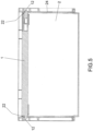
- Figure 5 shows a section through a Figure 4 shown container 2 closed with the lid 1.
- Both the rigid connectors 122 and the movable connectors 121 prevent the lid 1 from moving perpendicular to the lid plane 11 relative to the container 2.
- the grooves 123 in the connectors 12 engage with the side walls 24 of the container 2.
Landscapes
- Engineering & Computer Science (AREA)
- Mechanical Engineering (AREA)
- Ceramic Engineering (AREA)
- Closures For Containers (AREA)
- Containers Opened By Tearing Frangible Portions (AREA)
Applications Claiming Priority (2)
| Application Number | Priority Date | Filing Date | Title |
|---|---|---|---|
| DE102020119257.6A DE102020119257A1 (de) | 2020-07-21 | 2020-07-21 | Deckel zum Verschließen eines Behälters sowie System aus einem Behälter und einem Deckel |
| PCT/EP2021/069290 WO2022017847A1 (de) | 2020-07-21 | 2021-07-12 | Deckel zum verschliessen eines behälters sowie system aus einem behälter und einem deckel |
Publications (3)
| Publication Number | Publication Date |
|---|---|
| EP4185534A1 EP4185534A1 (de) | 2023-05-31 |
| EP4185534C0 EP4185534C0 (de) | 2025-02-05 |
| EP4185534B1 true EP4185534B1 (de) | 2025-02-05 |
Family
ID=76891078
Family Applications (1)
| Application Number | Title | Priority Date | Filing Date |
|---|---|---|---|
| EP21740552.1A Active EP4185534B1 (de) | 2020-07-21 | 2021-07-12 | Deckel zum verschliessen eines behälters sowie system aus einem behälter und einem deckel |
Country Status (10)
| Country | Link |
|---|---|
| US (1) | US12227346B2 (pl) |
| EP (1) | EP4185534B1 (pl) |
| CN (1) | CN116261548B (pl) |
| CA (1) | CA3189797A1 (pl) |
| DE (1) | DE102020119257A1 (pl) |
| ES (1) | ES3014235T3 (pl) |
| HU (1) | HUE070825T2 (pl) |
| MX (1) | MX2023000813A (pl) |
| PL (1) | PL4185534T3 (pl) |
| WO (1) | WO2022017847A1 (pl) |
Families Citing this family (1)
| Publication number | Priority date | Publication date | Assignee | Title |
|---|---|---|---|---|
| USD1081289S1 (en) * | 2024-08-27 | 2025-07-01 | Ming Zhao | Chocolate bar mold |
Family Cites Families (16)
| Publication number | Priority date | Publication date | Assignee | Title |
|---|---|---|---|---|
| HUP9602480A2 (en) * | 1995-02-17 | 1997-05-28 | Schoellerplast Transportbehael | Apparatus for locks locking alarm unit |
| WO1996025335A2 (de) * | 1995-02-17 | 1996-08-22 | Schoeller Plast Transportbehälter Systeme AG | Behältersystem für briefe |
| DE19718348A1 (de) | 1997-05-01 | 1998-11-12 | Sanacorp Ag | Transportbehälter |
| US5957292A (en) | 1997-08-01 | 1999-09-28 | Fluoroware, Inc. | Wafer enclosure with door |
| DE19822029B4 (de) * | 1998-05-15 | 2006-02-16 | Schoeller-Plast Sa | Zustellbehälter |
| FR2826637B1 (fr) * | 2001-06-29 | 2004-02-06 | Cit Alcatel | Dispositif de verrouillage/deverrouillage d'un couvercle amovible sur un boitier |
| DE20314261U1 (de) | 2003-09-13 | 2003-11-27 | Fritz Schäfer GmbH | Behälter, insbesondere aus Kunststoff |
| DE202004015212U1 (de) * | 2004-09-28 | 2005-02-10 | Fritz Schäfer GmbH | Lager- und Transportbehälter |
| US7909166B2 (en) * | 2008-08-14 | 2011-03-22 | Gudeng Precision Industrial Co, Ltd | Front opening unified pod with latch structure |
| US8276758B2 (en) * | 2008-08-14 | 2012-10-02 | Gudeng Precision Industrial Co, Ltd | Wafer container with at least one oval latch |
| US9199772B2 (en) * | 2012-03-30 | 2015-12-01 | David Krippendorf | Time lockable container and system |
| CN105993067B (zh) | 2013-04-26 | 2019-04-16 | 恩特格里斯公司 | 用于大直径晶片的具有锁止机构的晶片容器 |
| JP6457848B2 (ja) * | 2015-03-12 | 2019-01-23 | 岐阜プラスチック工業株式会社 | 運搬用容器 |
| DE202015103523U1 (de) | 2015-07-03 | 2015-08-31 | Ermis Medizintechnik E.K. | Verschlussmechanismus und Siebkorb mit einem Deckel, der den Verschlussmechanismus umfasst |
| DE102015121865B4 (de) | 2015-12-15 | 2018-07-26 | Bs Systems Gmbh & Co. Kg | Transportbox |
| DE102016104982A1 (de) * | 2016-03-17 | 2017-09-21 | Schoeller Allibert Gmbh | Behälter mit einer Deckelverriegelung |
-
2020
- 2020-07-21 DE DE102020119257.6A patent/DE102020119257A1/de active Pending
-
2021
- 2021-07-12 CN CN202180060517.8A patent/CN116261548B/zh active Active
- 2021-07-12 ES ES21740552T patent/ES3014235T3/es active Active
- 2021-07-12 PL PL21740552.1T patent/PL4185534T3/pl unknown
- 2021-07-12 EP EP21740552.1A patent/EP4185534B1/de active Active
- 2021-07-12 HU HUE21740552A patent/HUE070825T2/hu unknown
- 2021-07-12 US US18/016,940 patent/US12227346B2/en active Active
- 2021-07-12 CA CA3189797A patent/CA3189797A1/en active Pending
- 2021-07-12 WO PCT/EP2021/069290 patent/WO2022017847A1/de not_active Ceased
- 2021-07-12 MX MX2023000813A patent/MX2023000813A/es unknown
Also Published As
| Publication number | Publication date |
|---|---|
| MX2023000813A (es) | 2023-03-21 |
| PL4185534T3 (pl) | 2025-06-02 |
| CN116261548A (zh) | 2023-06-13 |
| US12227346B2 (en) | 2025-02-18 |
| US20230312198A1 (en) | 2023-10-05 |
| CN116261548B (zh) | 2025-07-25 |
| DE102020119257A1 (de) | 2022-01-27 |
| EP4185534C0 (de) | 2025-02-05 |
| EP4185534A1 (de) | 2023-05-31 |
| CA3189797A1 (en) | 2022-01-27 |
| ES3014235T3 (en) | 2025-04-21 |
| HUE070825T2 (hu) | 2025-07-28 |
| WO2022017847A1 (de) | 2022-01-27 |
Similar Documents
| Publication | Publication Date | Title |
|---|---|---|
| EP2686035B1 (de) | Trägerplatte und transport- und/oder lagereinrichtung für pharmazeutische behältnisse | |
| DE102015112204A1 (de) | Stapelbarer Behälter zur Ausbildung eines Behälterstapels aus gestapelten und insbesondere gekoppelten Behältern sowie Zubehör zum Bilden eines oberen Abschlusses des Behälterstapels | |
| DE102006041734A1 (de) | Vorrichtung zur Befestigung einer Airbageinheit in einer Baugruppe eines Kraftfahrzeugs, insbesondere in einem Lenkrad, durch Verrasten | |
| EP3254982A1 (de) | Transportbehälter | |
| EP2445752B1 (de) | Riegelelement | |
| WO2022017847A1 (de) | Deckel zum verschliessen eines behälters sowie system aus einem behälter und einem deckel | |
| EP3712084B1 (de) | Behälter aus kunststoff | |
| DE102007020277A1 (de) | Mehrteilige Palette | |
| DE102019125071B3 (de) | Transportsystem für Stückgüter | |
| EP4223656B1 (de) | Strukturkomponente eines baukastensystems und baugruppe zur verwendung in lagerungs- oder transportsystemen | |
| EP4331723B1 (de) | Set umfassend eine mikroplatte, einen deckel und eine vorrichtung zum lösen einer schnappverbindung zwischen mikroplatte und deckel | |
| EP3287318B1 (de) | Transport- und ladungssicherung für behälter | |
| DE102022000488A1 (de) | Großladungsträger | |
| DE202022103758U1 (de) | Verpackungssystem | |
| EP0236514B1 (de) | Transport- und Lagerkasten aus Kunststoff | |
| DE2352533A1 (de) | Quaderfoermiger verpackungsbehaelter | |
| DE102019110836A1 (de) | Transportbehälter | |
| WO2018149561A1 (de) | Stapelbarer und nestbarer behälter | |
| CH477329A (de) | Flaschentransportkasten aus Kunststoff | |
| EP4640574A1 (de) | Klappbehälter mit umlaufendem bodenrand | |
| DE102023200787A1 (de) | Gefahrgutbehälter | |
| EP2138413A1 (de) | Transportgestell zum Transport von Formteilen | |
| DE102022109976A1 (de) | Grossladungsträger | |
| DE102020202175A1 (de) | Twinsheet-Behältnis | |
| DE19534767A1 (de) | Drehriegelvorrichtung zur Verbindung von aufsetzbaren Containern, insbesondere auf stapelfähige Container, auf Fahrzeuge, auf Schiffe o. dgl. |
Legal Events
| Date | Code | Title | Description |
|---|---|---|---|
| STAA | Information on the status of an ep patent application or granted ep patent |
Free format text: STATUS: UNKNOWN |
|
| STAA | Information on the status of an ep patent application or granted ep patent |
Free format text: STATUS: THE INTERNATIONAL PUBLICATION HAS BEEN MADE |
|
| PUAI | Public reference made under article 153(3) epc to a published international application that has entered the european phase |
Free format text: ORIGINAL CODE: 0009012 |
|
| STAA | Information on the status of an ep patent application or granted ep patent |
Free format text: STATUS: REQUEST FOR EXAMINATION WAS MADE |
|
| 17P | Request for examination filed |
Effective date: 20230125 |
|
| AK | Designated contracting states |
Kind code of ref document: A1 Designated state(s): AL AT BE BG CH CY CZ DE DK EE ES FI FR GB GR HR HU IE IS IT LI LT LU LV MC MK MT NL NO PL PT RO RS SE SI SK SM TR |
|
| DAV | Request for validation of the european patent (deleted) | ||
| DAX | Request for extension of the european patent (deleted) | ||
| GRAP | Despatch of communication of intention to grant a patent |
Free format text: ORIGINAL CODE: EPIDOSNIGR1 |
|
| STAA | Information on the status of an ep patent application or granted ep patent |
Free format text: STATUS: GRANT OF PATENT IS INTENDED |
|
| INTG | Intention to grant announced |
Effective date: 20240221 |
|
| GRAS | Grant fee paid |
Free format text: ORIGINAL CODE: EPIDOSNIGR3 |
|
| GRAA | (expected) grant |
Free format text: ORIGINAL CODE: 0009210 |
|
| STAA | Information on the status of an ep patent application or granted ep patent |
Free format text: STATUS: THE PATENT HAS BEEN GRANTED |
|
| AK | Designated contracting states |
Kind code of ref document: B1 Designated state(s): AL AT BE BG CH CY CZ DE DK EE ES FI FR GB GR HR HU IE IS IT LI LT LU LV MC MK MT NL NO PL PT RO RS SE SI SK SM TR |
|
| REG | Reference to a national code |
Ref country code: GB Ref legal event code: FG4D Free format text: NOT ENGLISH |
|
| REG | Reference to a national code |
Ref country code: CH Ref legal event code: EP |
|
| REG | Reference to a national code |
Ref country code: IE Ref legal event code: FG4D Free format text: LANGUAGE OF EP DOCUMENT: GERMAN |
|
| REG | Reference to a national code |
Ref country code: DE Ref legal event code: R096 Ref document number: 502021006582 Country of ref document: DE |
|
| REG | Reference to a national code |
Ref country code: ES Ref legal event code: FG2A Ref document number: 3014235 Country of ref document: ES Kind code of ref document: T3 Effective date: 20250421 |
|
| U01 | Request for unitary effect filed |
Effective date: 20250415 |
|
| U50 | Request for re-establishment of rights filed [unitary effect] |
Free format text: RE-ESTABLISHMENT OF RIGHTS REQUESTED DUE TO A LATE FILING ON THE REQUEST FOR UNITARY EFFECT Effective date: 20250424 |
|
| REG | Reference to a national code |
Ref country code: NL Ref legal event code: MP Effective date: 20250205 |
|
| U07 | Unitary effect registered |
Designated state(s): AT BE BG DE DK EE FI FR IT LT LU LV MT NL PT RO SE SI Effective date: 20250522 |
|
| U53 | Request for re-establishment of rights accepted [unitary effect] |
Effective date: 20250522 |
|
| PG25 | Lapsed in a contracting state [announced via postgrant information from national office to epo] |
Ref country code: RS Free format text: LAPSE BECAUSE OF FAILURE TO SUBMIT A TRANSLATION OF THE DESCRIPTION OR TO PAY THE FEE WITHIN THE PRESCRIBED TIME-LIMIT Effective date: 20250505 |
|
| PG25 | Lapsed in a contracting state [announced via postgrant information from national office to epo] |
Ref country code: NO Free format text: LAPSE BECAUSE OF FAILURE TO SUBMIT A TRANSLATION OF THE DESCRIPTION OR TO PAY THE FEE WITHIN THE PRESCRIBED TIME-LIMIT Effective date: 20250505 Ref country code: IS Free format text: LAPSE BECAUSE OF FAILURE TO SUBMIT A TRANSLATION OF THE DESCRIPTION OR TO PAY THE FEE WITHIN THE PRESCRIBED TIME-LIMIT Effective date: 20250605 |
|
| PG25 | Lapsed in a contracting state [announced via postgrant information from national office to epo] |
Ref country code: HR Free format text: LAPSE BECAUSE OF FAILURE TO SUBMIT A TRANSLATION OF THE DESCRIPTION OR TO PAY THE FEE WITHIN THE PRESCRIBED TIME-LIMIT Effective date: 20250205 |
|
| PG25 | Lapsed in a contracting state [announced via postgrant information from national office to epo] |
Ref country code: GR Free format text: LAPSE BECAUSE OF FAILURE TO SUBMIT A TRANSLATION OF THE DESCRIPTION OR TO PAY THE FEE WITHIN THE PRESCRIBED TIME-LIMIT Effective date: 20250506 |
|
| REG | Reference to a national code |
Ref country code: HU Ref legal event code: AG4A Ref document number: E070825 Country of ref document: HU |
|
| PG25 | Lapsed in a contracting state [announced via postgrant information from national office to epo] |
Ref country code: SM Free format text: LAPSE BECAUSE OF FAILURE TO SUBMIT A TRANSLATION OF THE DESCRIPTION OR TO PAY THE FEE WITHIN THE PRESCRIBED TIME-LIMIT Effective date: 20250205 |
|
| PG25 | Lapsed in a contracting state [announced via postgrant information from national office to epo] |
Ref country code: SK Free format text: LAPSE BECAUSE OF FAILURE TO SUBMIT A TRANSLATION OF THE DESCRIPTION OR TO PAY THE FEE WITHIN THE PRESCRIBED TIME-LIMIT Effective date: 20250205 |
|
| PLBE | No opposition filed within time limit |
Free format text: ORIGINAL CODE: 0009261 |
|
| STAA | Information on the status of an ep patent application or granted ep patent |
Free format text: STATUS: NO OPPOSITION FILED WITHIN TIME LIMIT |
|
| REG | Reference to a national code |
Ref country code: CH Ref legal event code: L10 Free format text: ST27 STATUS EVENT CODE: U-0-0-L10-L00 (AS PROVIDED BY THE NATIONAL OFFICE) Effective date: 20251217 |
|
| 26N | No opposition filed |
Effective date: 20251106 |
|
| PGFP | Annual fee paid to national office [announced via postgrant information from national office to epo] |
Ref country code: HU Payment date: 20251223 Year of fee payment: 5 |
|
| PGFP | Annual fee paid to national office [announced via postgrant information from national office to epo] |
Ref country code: CZ Payment date: 20251223 Year of fee payment: 5 |
|
| PGFP | Annual fee paid to national office [announced via postgrant information from national office to epo] |
Ref country code: PL Payment date: 20251219 Year of fee payment: 5 |
|
| PGFP | Annual fee paid to national office [announced via postgrant information from national office to epo] |
Ref country code: ES Payment date: 20251229 Year of fee payment: 5 |
|
| U21 | Renewal fee for the european patent with unitary effect paid with additional fee |
Year of fee payment: 5 Effective date: 20251229 |
|
| REG | Reference to a national code |
Ref country code: CH Ref legal event code: H13 Free format text: ST27 STATUS EVENT CODE: U-0-0-H10-H13 (AS PROVIDED BY THE NATIONAL OFFICE) Effective date: 20260224 |
|
| GBPC | Gb: european patent ceased through non-payment of renewal fee |
Effective date: 20250712 |
|
| PG25 | Lapsed in a contracting state [announced via postgrant information from national office to epo] |
Ref country code: GB Free format text: LAPSE BECAUSE OF NON-PAYMENT OF DUE FEES Effective date: 20250712 |
|
| PG25 | Lapsed in a contracting state [announced via postgrant information from national office to epo] |
Ref country code: CH Free format text: LAPSE BECAUSE OF NON-PAYMENT OF DUE FEES Effective date: 20250731 |