EP4175879B1 - Ruderkoker für ein wasserfahrzeug, wasserfahrzeug mit einem ruderkoker und verfahren zur herstellung eines ruderkokers - Google Patents
Ruderkoker für ein wasserfahrzeug, wasserfahrzeug mit einem ruderkoker und verfahren zur herstellung eines ruderkokers Download PDFInfo
- Publication number
- EP4175879B1 EP4175879B1 EP21737685.4A EP21737685A EP4175879B1 EP 4175879 B1 EP4175879 B1 EP 4175879B1 EP 21737685 A EP21737685 A EP 21737685A EP 4175879 B1 EP4175879 B1 EP 4175879B1
- Authority
- EP
- European Patent Office
- Prior art keywords
- holder
- receiving shaft
- tube
- trunk
- complement
- Prior art date
- Legal status (The legal status is an assumption and is not a legal conclusion. Google has not performed a legal analysis and makes no representation as to the accuracy of the status listed.)
- Active
Links
Images


Classifications
-
- B—PERFORMING OPERATIONS; TRANSPORTING
- B63—SHIPS OR OTHER WATERBORNE VESSELS; RELATED EQUIPMENT
- B63H—MARINE PROPULSION OR STEERING
- B63H25/00—Steering; Slowing-down otherwise than by use of propulsive elements; Dynamic anchoring, i.e. positioning vessels by means of main or auxiliary propulsive elements
- B63H25/06—Steering by rudders
- B63H25/38—Rudders
-
- B—PERFORMING OPERATIONS; TRANSPORTING
- B63—SHIPS OR OTHER WATERBORNE VESSELS; RELATED EQUIPMENT
- B63B—SHIPS OR OTHER WATERBORNE VESSELS; EQUIPMENT FOR SHIPPING
- B63B3/00—Hulls characterised by their structure or component parts
- B63B3/14—Hull parts
- B63B3/40—Stern posts; Stern frames
-
- B—PERFORMING OPERATIONS; TRANSPORTING
- B63—SHIPS OR OTHER WATERBORNE VESSELS; RELATED EQUIPMENT
- B63B—SHIPS OR OTHER WATERBORNE VESSELS; EQUIPMENT FOR SHIPPING
- B63B73/00—Building or assembling vessels or marine structures, e.g. hulls or offshore platforms
- B63B73/20—Building or assembling prefabricated vessel modules or parts other than hull blocks, e.g. engine rooms, rudders, propellers, superstructures, berths, holds or tanks
-
- B—PERFORMING OPERATIONS; TRANSPORTING
- B63—SHIPS OR OTHER WATERBORNE VESSELS; RELATED EQUIPMENT
- B63B—SHIPS OR OTHER WATERBORNE VESSELS; EQUIPMENT FOR SHIPPING
- B63B73/00—Building or assembling vessels or marine structures, e.g. hulls or offshore platforms
- B63B73/40—Building or assembling vessels or marine structures, e.g. hulls or offshore platforms characterised by joining methods
Definitions
- the present invention relates to a rudder trunk for a watercraft, comprising a trunk tube, a receiving shaft and a holder for holding the trunk tube in the receiving shaft, wherein, when the trunk tube is arranged in the receiving shaft, an intermediate space is provided between the trunk tube and the receiving shaft.
- the present invention further relates to a watercraft with a rudder trunk and a method for producing a rudder trunk.
- rudder trunks For the storage of large rudders, for example in merchant ships or container ships, so-called rudder trunks are used in the state of the art.
- the rudder trunk of a rudder system is used to store the rudder shaft and to transfer the rudder forces to the watercraft.
- a rudder trunk When arranged on the ship, a rudder trunk comprises a receiving shaft, which is arranged in the hull, and a trunk tube, which is arranged in the receiving shaft.
- the trunk tube can be fixed in the receiving shaft by welding or gluing.
- the rudder shaft is inserted into the trunk tube fixed in the receiving shaft and is supported there with axial and radial bearings.
- the at least one holder element and the at least one holder complement can be and/or are arranged in a force-fitting and/or form-fitting manner on one another, so that in the state of the coker tube arranged in the receiving shaft, in particular in a state of the rudder coker comprising coker tube and receiving shaft arranged on the watercraft, a movement of the coker tube in the receiving shaft in an axial direction of the coker tube is hindered or prevented.
- At least two, preferably at least three, more preferably at least four, particularly preferably exactly four, holder elements are provided, and/or that at least two, preferably at least three, more preferably at least four, particularly preferably exactly four, holder complements are provided.
- the at least one holder element is formed in one piece with the coker tube and/or is connected to the coker tube in a materially bonded and/or force-locking and/or positively locking manner, and/or that the at least one holder complement is formed in one piece with the receiving shaft and/or is connected to the receiving shaft in a materially bonded and/or force-locking and/or positively locking manner.
- the material-locking connection between the holder element and the casing tube or between the holder complement and the receiving shaft can be achieved, for example, by welding or gluing.
- the holder complement is designed as a U-profile body and the holder element as a pin, bolt, projection, plate or web
- the holder element can be hooked into the U-profile body.
- the holder element is inserted between the legs of the U-profile body and placed on a base section of the U-profile body.
- twisting of the coker tube in the receiving shaft can also be prevented or restricted, since the holder element designed as a pin, bolt, plate, web or projection strikes the legs of the U-profile body when attempting to twist the coker tube.
- the interaction of the holder element and the holder complement provides a rotation brake.
- the holder element on the coker tube is designed as a U-shaped profile body, while the holder complement on the receiving shaft is designed as a pin, bolt, projection, plate or web. In both The only thing that needs to be considered is the alignment of the U-profile body.
- the legs of the U-profile body in the receiving shaft must be aligned vertically upwards so that the holder element of the coker tube, designed as a pin, bolt, projection, plate or web, can be inserted into the U-profile body from above.
- Either the holder element or the holder complement can be a threaded bolt.
- the corresponding holder complement or the corresponding holder element is then designed as a receptacle, in particular as a bore, preferably with an internal thread.
- the threaded bolt can be screwed into the receptacle or into the bore with the internal thread.
- the coker tube can be aligned or adjusted in the receiving shaft, in particular in a radial direction of the receiving shaft.
- the holder complement designed as a clamping element and the corresponding holder element can also be designed differently from a clamping ring and a recess, as long as the clamping element and the corresponding holder element together bring about a non-positive and/or positive clamping between the coker tube and the receiving shaft.
- the holder elements and/or the holder complements are preferably aligned slightly inclined downwards and/or upwards. This slight inclination in the axial direction can ensure a particularly advantageous alignment and adjustment of the coker tube in the receiving shaft.
- a central axis of the coker tube is aligned with a central axis of the receiving shaft, this can be done by moving the coker tube approximately in a radial direction in the receiving shaft.
- One of the bolts is then guided slightly downwards along the slightly downward-inclined U-profile body, while the other bolt in the second U-profile body is guided slightly upwards.
- This inclines the central axis of the coker tube with respect to the central axis of the receiving shaft.
- a corresponding effect also occurs with at least three or at least four or exactly four holder elements or holder complements.
- a uniform arrangement of holder elements and holder complements enables easy production as well as easy alignment and adjustment of the coker tube in the receiving shaft.
- the at least two holder elements are arranged at a distance in the circumferential direction over the outer circumference of the coker tube, and/or that the at least two holder complements are arranged at a distance in the circumferential direction over the inner circumference of the receiving shaft, such that when the coker tube is inserted into the receiving shaft, the holder elements can be guided past the holder complements in the axial direction.
- the coker tube can be adjusted, in particular aligned, in the receiving shaft in the state arranged in the receiving shaft, in particular in a state of the rudder coker arranged on the watercraft comprising the coker tube and the receiving shaft, further in particular when the intermediate space is not filled.
- the adjustment of the coker tube arranged in the receiving shaft can therefore be carried out particularly advantageously when it is arranged on the watercraft, i.e. in relation to an actual propeller shaft or an actual stern tube.
- the adjustment is preferably carried out when the gap has not yet been filled with a connecting means. However, it can also be carried out when the gap is filled, preferably in some areas, with a connecting means. If the connecting means is a cast plastic, alignment or adjustment can be carried out while the cast plastic is hardening.
- the coker tube can be displaced inside the receiving shaft for alignment and adjustment with respect to a radial direction of the receiving shaft.
- adjustment means can be provided, wherein the adjustment means are designed such that, in particular when holder elements and holder complements are arranged next to one another, a position and/or orientation of the coker tube in the receiving shaft, in particular the position of the coker tube in the receiving shaft with respect to a radial direction of the receiving shaft and/or an angle between a central axis of the coker tube and a central axis of the receiving shaft, can be adjusted.
- the adjusting means can be additional elements, but the adjusting means can also be part of the holder elements and/or the holder complements.
- the holder elements and/or the holder complements can be adjustable.
- an angle of inclination of the holder elements and/or the holder complements can be adjusted.
- the adjusting means are adjusting screws and/or shims, preferably washers, wherein the adjusting means are preferably arranged on the at least one holder element and/or on the at least one holder complement.
- the intermediate space between the outer wall of the coker tube and the inner wall of the receiving shaft expands or contracts at least in some areas in the axial direction of the coker tube.
- a gap size of the intermediate space between the outer wall of the coker tube and the inner wall of the receiving shaft increases or decreases at least in some areas in the axial direction of the coker tube.
- the gap size of the intermediate space between the outer wall of the coker tube and the inner wall of the receiving shaft increases at least in some areas in the axial direction of the coker tube, viewed upwards, i.e. in the state of the rudder coker or the receiving shaft arranged on the watercraft, in particular on the ship, in the direction of the watercraft hull, in particular the hull of the ship.
- the increase in the gap size can be achieved by increasing the inner diameter of the receiving shaft in the state arranged on the ship in the direction of the hull at least in some areas, and/or that the outer diameter of the coker tube decreases at least in some areas in the direction of the hull when arranged on the ship.
- a wall thickness of the coker tube decreases in the axial direction of the coker tube, wherein the inner diameter of the coker tube remains constant in the axial direction and the outer diameter decreases.
- the coker tube When the coker tube is arranged in the receiving shaft, the coker tube is arranged in the receiving shaft over a clamping height.
- the clamping height is preferably formed between a lower end or an outside of the receiving shaft and an upper region, in particular an upper end, of the coker tube.
- the gap size preferably increases at least in some areas over the course of the clamping height.
- a lower area of the clamping height can particularly preferably have a constant gap size. To increase the gap size in some areas, this increases above the area of the constant gap size.
- the gap size can decrease again in an upper area of the clamping height in the axial direction.
- the decrease in the gap size in the upper area of the clamping height can be caused by the holder complements and/or holder elements of the holder protruding into the gap.
- the decrease in the gap size in the upper area of the clamping height can also be achieved by a flange, in particular a circumferential flange, on the inner wall of the receiving shaft or the outer wall of the coker tube in the upper area.
- the gap dimension of the intermediate space between the outer wall of the coker tube and the inner wall of the receiving shaft at least in some areas, viewed downwards in the axial direction of the coker tube, that is to say in the state of the rudder coker or the receiving shaft arranged on the watercraft, in particular on the ship, in the direction pointing away from the watercraft hull, in particular from the ship hull.
- the intermediate space can be or is filled with a connecting means, preferably with a cast plastic, in particular cast resin, at least in regions.
- the gap is preferably only filled with the connecting means, in particular the cast plastic, after the alignment and adjustment of the coker pipe in the receiving shaft, at least in part.
- the connecting means creates a firm connection between the coker pipe and the receiving shaft, for example as soon as the cast plastic has hardened, a fixed and aligned or adjusted coker pipe is obtained in the receiving shaft, which provides a particularly high hydrodynamic efficiency.
- the holder elements and holder complements which preferably remain in the gap, prevent the coker pipe from slipping even if the connecting means fails, for example if the cast plastic leaks out.
- the intermediate space is only filled with the connecting means in the lower region of the clamping height with a constant gap.
- the intermediate space can also only be filled with the connecting means in the upper region of the clamping height, in particular in the region of the holder element and/or the holder complement and/or the flange.
- the intermediate space in the region of the widening gap is not filled with the connecting means.
- the outside of the rudder tube corresponds to the outside of the ship's hull, preferably the area of the ship's hull that surrounds the outside opening of the receiving shaft.
- the tube can be inserted into the receiving shaft from below.
- a sealing element in particular a sealing sleeve, is then attached to the outside of the ship's hull and thus to an outside of the rudder tube, which seals the Seals the gap between the rudder tube and the receiving shaft.
- the gap between the rudder tube and the receiving shaft can be filled with a connecting agent, in particular with a cast plastic, the sealing element preventing the connecting agent from escaping from the gap, in particular downwards towards the outside of the rudder tube or towards the outside of the hull.
- the sealing element can remain on the hull or on the outside of the rudder tube.
- the sealing element it is also possible for the sealing element to be removed after filling the gap with the connecting agent. If the sealing element remains on the hull or on the outside of the rudder tube, further protection is offered against the connecting agent, in particular the cast plastic, escaping. If, on the other hand, the sealing element is removed, it can be reused.
- sealing element is designed in one piece, in particular in one piece, or in several parts.
- a multi-part design of the sealing element allows a particularly simple attachment of the sealing element to the outside of the rudder trunk or to the outside of the hull.
- the sealing element comprises a, in particular annular, frame and/or an O-ring and/or an elastomer.
- sealing element has at least one breakthrough, in particular an opening or a passage, wherein the connecting means can be introduced through the opening, in particular into the intermediate space.
- the connecting means can be inserted through the opening, in particular through the opening or passage. into the gap from the outside of the vessel into the gap. This provides a particularly simple way of filling the gap.
- the openings can be designed to be closable in order to prevent the connecting means, in particular the cast plastic, from escaping after the gap has been filled. Furthermore, hoses for introducing the connecting means can be passed through the openings. This can prevent the formation of bubbles in the connecting means, in particular in the cast plastic.
- the connecting means in particular the cast plastic, is liquefiable, preferably by heat input, so that the coker pipe can be removed from the receiving shaft after the liquefaction of the connecting means.
- the connecting means in particular the cast plastic, is designed to be liquefiable by the introduction of heat, replacing the coker tube is made easier. If it becomes necessary to replace the coker tube, the connecting means can be liquefied by the introduction of heat.
- the coker tube can then be removed from the receiving shaft on the hull. In a preferred embodiment, the coker tube must be lifted vertically after the connecting means has liquefied so that the coker tube moves upwards in the receiving shaft.
- the coker tube is then rotated so that the holder elements and holder complements, which were previously aligned with one another, are rotated relative to one another.
- the coker tube can then be guided downwards out of the receiving shaft in the axial direction, with the holder elements being guided past the holder complements. A new coker tube can then be inserted.
- heating elements in particular heating wires, are arranged in the intermediate space and are preferably embedded in the connecting means.
- heating elements in particular heating wires
- replacing the coker tube is made even easier.
- the heating elements, in particular the heating wires allow heat energy to be introduced into the connecting material in a homogeneous manner for the replacement, so that it liquefies evenly.
- recesses in particular grooves or bores, are arranged on the outside and/or on the inside of the coker tube and/or the receiving shaft, wherein signal conducting means, in particular cables, are preferably arranged in the recesses.
- grooves or holes can be provided in the trunk tube or in the receiving shaft in order to guide corresponding signal conductors, such as cables, therein.
- the signal conductors can be guided in the space between the trunk tube and the receiving shaft and, with further advantage, can be led out at the least stressed points of the receiving shaft or trunk tube.
- the holder elements and holder complements therefore preferably represent rotation brakes. This further improves the force transmission of the rudder shaft into the hull.
- the holder complements are designed as U-profile bodies and if the holder elements are designed as bolts, pins, projections, webs or plates that are arranged between the legs of the holder complements designed as U-profile bodies, a twisting of the coker tube in the receiving shaft is prevented. However, a slight twisting can be permitted. This can happen if the distance between the legs of the U-profile bodies is greater than the width of the holder elements arranged between the legs. A small permitted degree of rotation can lead to Aligning the coker tube in the receiving shaft compensates for manufacturing tolerances.
- a further solution to the problem underlying the invention consists in the provision of a rudder arrangement for a watercraft, in particular a ship, with a rudder and a rudder trunk as described above.
- a further solution to the problem underlying the invention consists in the provision of a watercraft, in particular a ship, with a rudder trunk as described above.
- An additional solution to the problem underlying the invention consists in the provision of a coker tube for a rudder coker as described above, wherein the coker tube has at least one holder element.
- the holder element can be designed according to the embodiments described above.
- a still further solution to the problem underlying the invention consists in the provision of a receiving shaft for a rudder trunk as described above, wherein the receiving shaft has at least one holder complement.
- the holder complement can be designed according to the embodiments described above.
- a still further solution to the problem underlying the invention consists in a kit for a previously described rudder trunk comprising at least one, in particular previously described, holder element and comprising at least one, in particular previously described, holder complement, wherein the kit preferably comprises a trunk tube and/or a receiving shaft.
- the coker tube and receiving shaft can also be designed according to one of the embodiments described above.
- the object underlying the invention is achieved by providing a method for producing a rowing trunk, in particular as described above, with a receiving shaft as described above and a trunk tube as described above in a watercraft, wherein a watercraft, in particular a ship, further in particular a stern section, is provided, wherein the receiving shaft is arranged in the watercraft, wherein the trunk tube is introduced into the receiving shaft, wherein the at least one holder element is guided past the at least one holder complement, wherein the trunk tube is rotated so that the at least one holder element and the at least one holder complement are aligned in an axial direction of the trunk tube and/or the receiving shaft, wherein the trunk tube is moved in the axial direction so that the at least one holder element and the at least one holder complement are arranged next to one another, in particular placed on one another.
- the method according to the invention allows in particular that a coker pipe is introduced into a receiving shaft, wherein the receiving shaft is arranged in a rear section of a ship's hull and wherein the rear section is aligned with the upper deck upwards or wherein the ship's hull is aligned with the keel downwards.
- the coker pipe does not have to be introduced from above into a receiving shaft of a rear section turned upside down, but can be introduced into the receiving shaft from below with the ship's hull aligned with the keel downwards. This offers the possibility of aligning the coker pipe with the actual propeller shaft and the actual stern tube.
- the watercraft is aligned with a keel downwards and that the coker pipe is inserted into the receiving shaft from below, viewed in the vertical direction.
- the possibility of inserting the coker tube in a vertical direction from below into the receiving shaft allows the adjustment or alignment of the coker tube with respect to the actual propeller axis and the actual stern tube.
- the coker tube is aligned in the receiving shaft with adjusting means, wherein the alignment is carried out relative to a propeller axis and/or a stern tube of the watercraft.
- the adjusting means can be part of the holder elements or the holder complements or can be identical to the holder elements or holder complements. Furthermore, the adjusting means can also be designed as washers or similar.
- an intermediate space between the coker tube and the receiving shaft is filled with a connecting means, in particular a cast plastic, and wherein the connecting means, in particular the cast plastic, is cured.
- the coker tube aligned with the actual propeller axis or the actual stern tube can be fixed in the receiving shaft.
- the sealing agent is applied to the outside of the rudder trunk, in particular on the outside of the watercraft, and further in particular on the outside of the hull, remains or is removed.
- heating elements in particular heating wires, are arranged in the intermediate space.
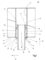
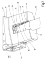
- Fig. 1 shows a rowing trunk 100 comprising a trunk tube 10 and a receiving shaft 11.
- the rowing trunk 100 is arranged in a hull 12 of a watercraft 13.
- the hull 12 has an outer side 14.
- the trunk tube 10 is designed as a hollow tube 15 and is inserted in a vertical direction 16 from the outer side 14 of the hull 12 into the receiving shaft 11 from below.
- a gap 19 is formed between the outer wall 17 of the trunk tube 10 and the inner wall 18 of the receiving shaft 11 when the trunk tube 10 is arranged in the receiving shaft 11.
- the rudder trunk 100 comprises a holder 20 for holding the trunk tube 10 in the receiving shaft 11.
- the holder 20 comprises holder elements 21 which are fastened to the outer wall 17 of the trunk tube 10 in a materially bonded, positively bonded or non-positively bonded manner.
- the holder 20 also comprises holder complements 22 which are arranged on the inner wall 18 of the receiving shaft 11 in a materially bonded or non-positively bonded manner.
- Each of the holder complements 22 protrudes in a radial direction 23 from the inner wall 18 of the receiving shaft 11 into the intermediate space 19.
- each of the holder elements 21 protrudes from the outer wall 17 of the trunk tube 10 in the radial direction 23 into the intermediate space 19.
- a connecting means 24 which is designed as a cast plastic 25 and ensures a secure fixation of the coker tube 10 in the receiving shaft 11.
- the coker tube 10 also extends in an axial direction 26.
- a first embodiment of the holder 20 is shown.
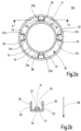
- Fig. 2a shows a top view of the coker tube 10 and the receiving shaft 11 against the axial direction 26.
- Fig. 2b shows a view of the holder complement 22 arranged on the inner wall 18 of the receiving shaft 11 and the holder element 21 arranged on the outer wall 17 of the coker tube 10 along the section line AA from Fig. 2a .
- the coker tube 10 has four holder elements 21a to 21d, which protrude from the outer wall 17 of the coker tube 10 into the intermediate space 19.
- Four holder complements 22a to 22d are arranged on the inner wall 18 of the receiving shaft 11, which also protrude into the intermediate space 19.
- the holder elements 21a to 21d and the holder complements 22a to 22d are evenly distributed over the outer circumference of the coker tube 10 or spaced over the inner circumference of the receiving shaft 11.
- the holder complements 22 or 22a to 22d are designed as profile bodies 29 and in particular as U-profile bodies 28.
- the U-profile bodies 28 have legs 30 and a base section 31.
- the holder elements 21 or 21a to 21d are designed as webs 32 and are placed on the base section 31 of the holder complements 22 or 22a to 22d designed as U-profile bodies 28.
- the legs 30 of the U-profile body 28 also serve as a rotation brake 33.
- the coker tube 10 can thus be held in the Fig. 2a and 2b shown arrangement only slightly rotate in the receiving shaft 11 before the webs 32 of the holder elements 21a to 21d abut the legs 30 of the U-profile body 28.
- the gap 19 between the coker tube 10 and the receiving shaft 11 is not filled.
- the coker tube 10 can be aligned or adjusted in the receiving shaft 11.
- the Fig. 2b By arranging the support elements 34 between the web 32 and the base section 31 of the U-profile body 28, the coker tube 10 can be adjusted in the receiving shaft 11.
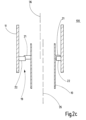
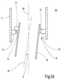
- Fig. 2c and 2d The possibilities of adjusting the coker tube 10 in the receiving shaft 11 are shown.
- the coker tube 10 is displaced laterally in the receiving shaft 11 in such a way that the central axis 35 of the coker tube 10 is laterally offset from the central axis 36 of the receiving shaft 11.
- Fig. 2c the coker tube 10 is displaced laterally in the receiving shaft 11 in such a way that the central axis 35 of the coker tube 10 is laterally offset from the central axis 36 of the receiving shaft 11.
- the coker tube is guided from the outside 14 of the hull 12 in the vertical direction 16 ( Fig. 1 ) is inserted into the receiving slot 11.
- the coker tube 10 is rotated relative to the receiving shaft 11 such that the holder elements 21a to 21d and the holder complements 22a to 22d are not aligned with each other.
- the coker tube 10 can be introduced into the receiving shaft 11 in the vertical direction 16 such that the holder elements 21a to 21d are guided past the holder complements 22a to 22d until the holder elements 21a to 21d are arranged above the holder complements 22a to 22d.
- the holder elements 21a to 21d can then be aligned with the holder elements 22a to 22d by rotating the coker tube 10 about the central axis 35 of the coker tube 10, as shown in the top view in Fig. 2a shown.
- the coker tube 10 can then be moved downwards in the axial direction 26 or against the vertical direction 16, so that the holder elements 21a to 21d, which are designed in particular as webs 32, are arranged on the holder complements 22a to 22d, which are designed in particular as U-profile bodies 28.
- a holder 20 is formed which prevents or hinders movement of the coker tube in the axial direction 26 within the receiving shaft 11 ( Fig. 1 ).
- the coker tube 10 can then be aligned, in particular on a propeller shaft or on a stern tube.
- the intermediate space 19 is then filled with a connecting means 24.
- FIG. 4 A further embodiment of the holder 20 is shown. Compared to the design of the Fig. 1 and 2a The design differs according to Fig. 4 merely in that the holder elements 21 or 21a to 21d designed as webs 32, which protrude in the radial direction 23 into the intermediate space 19 between the coker tube 10 and the receiving shaft 11, are additionally inclined upwards against the axial direction 26. This means that by moving the coker tube 10 in the receiving shaft 11 in the radial direction 23, the holder elements 21 or 21a to 21d in the holder complements 22 or 22a to 22d designed as U-profile bodies 28 receive an additional component of movement in or against the axial direction 26 due to the inclination. The central axis 35 of the coker tube 10 is thereby aligned with the central axis 36 of the receiving shaft 11.
- FIG. 5a and 5b A further embodiment of the holder 20 is shown in Fig. 5a and 5b shown.
- the holder element 21 in the coker tube 10 is designed as a recess 37, in particular as a groove 38.
- the recess 37 is designed to run all the way around the coker tube 10.
- the holder complement 22 is designed as a clamping element in the form of a clamping ring 39 and is arranged in a form-fitting manner on the receiving shaft 11 via a second groove 40 running around the inner wall 18 of the receiving shaft 11.
- the clamping ring 39 is not designed to be completely closed, but rather has Fig.
- the clamping ring 39 When inserting the coker tube 10 into the receiving shaft 11, the clamping ring 39 must first be widened so that the coker tube 10 can be guided through the clamping ring 39. As soon as the recess 37 or the groove 38 of the coker tube 10 is arranged at the height of the clamping ring 39, the clamping ring 39 is relaxed so that it, as in the Fig. 5a shown, engages in the recess 37 or the groove 38 of the coker tube 10. This prevents movement of the coker tube 10 in the axial direction 26 of the coker tube 10 in the receiving shaft 11.
- clamping ring 39 and the groove 38 instead of the clamping ring 39 and the groove 38, other clamping elements and suitably designed holder elements 21 can also be used as the holder complement 22, which bring about a force-fitting and/or form-fitting clamping between the coker tube 10 and the receiving shaft 11.
- a sealing element 42 is also shown, which is arranged on the outside 14 of the hull 12.
- the sealing element 42 is designed as a sealing sleeve 43 and has an opening 44 through which the connecting means 24, in particular the cast plastic 25, can be introduced into the intermediate space 19 between the coker tube 10 and the receiving shaft 11.
- the connecting means 24 After the connecting means 24 has hardened, the sealing sleeve 43 can either remain on the outside 14 of the hull 12. Alternatively, it is possible for the sealing sleeve 43 to be removed from the outside 14 of the hull 12.
- the Fig. 6 and 7 show another rowing trunk 100.
- the rowing trunk 100 has a receiving shaft 11, which is arranged on a hull 12 of a watercraft 13.
- a trunk pipe 10 is arranged in the receiving shaft 11 in such a way that a gap 19 is formed between the outer wall 17 of the trunk pipe 10 and the inner wall 18 of the receiving shaft 11.
- the trunk pipe 10 is arranged in the receiving shaft 11 over a clamping height 45. In a lower area 46 of the clamping height 45, the intermediate space 19 between the inner wall 18 of the receiving shaft 11 and the outer wall 17 of the coker tube 10 has a constant gap dimension 47.
- a central region 48 is provided above the lower region 46 of the clamping height 45, in which the gap dimension 47 between the outer wall 17 of the coker tube 10 and the inner wall 18 of the receiving shaft 11 increases in the direction of the hull 12.
- the coker tube 10 has a wall thickness 49 that decreases towards the top.
- holder elements 21 are arranged on the outside of the coker tube 10.
- Corresponding holder complements 22 are arranged on the inner wall 18 of the receiving shaft 11. The holder elements 21 or holder complements 22 reduce the gap size 47 in the upper region 50 of the clamping height 45.
- a circumferential flange can also be provided.
- a connecting means 24, such as cast plastic 25, is arranged in the upper region 50 in the region of the holder elements 21 and holder complements 22.
- a connecting means 24 is also provided in the lower region 46 of constant gap size 47.
- the middle region 48 of the clamping height 45 is the middle region 48 of the clamping height 45, whereby the gap 19 in the middle region 48 is not filled with a connecting means 24.
Landscapes
- Engineering & Computer Science (AREA)
- Chemical & Material Sciences (AREA)
- Combustion & Propulsion (AREA)
- Mechanical Engineering (AREA)
- Ocean & Marine Engineering (AREA)
- Architecture (AREA)
- Structural Engineering (AREA)
- Mutual Connection Of Rods And Tubes (AREA)
Priority Applications (1)
| Application Number | Priority Date | Filing Date | Title |
|---|---|---|---|
| HRP20250433TT HRP20250433T1 (hr) | 2020-07-03 | 2021-07-01 | Kanal za vratilo kormila za plovilo, plovilo koje ima kanal za vratilo kormila i postupak proizvodnje kanala za vratilo kormila |
Applications Claiming Priority (2)
| Application Number | Priority Date | Filing Date | Title |
|---|---|---|---|
| DE202020103872.9U DE202020103872U1 (de) | 2020-07-03 | 2020-07-03 | Ruderkoker für ein Wasserfahrzeug und Wasserfahrzeug mit einem Ruderkoker |
| PCT/EP2021/068258 WO2022003133A1 (de) | 2020-07-03 | 2021-07-01 | Ruderkoker für ein wasserfahrzeug, wasserfahrzeug mit einem ruderkoker und verfahren zur herstellung eines ruderkokers |
Publications (2)
| Publication Number | Publication Date |
|---|---|
| EP4175879A1 EP4175879A1 (de) | 2023-05-10 |
| EP4175879B1 true EP4175879B1 (de) | 2025-03-05 |
Family
ID=72334010
Family Applications (1)
| Application Number | Title | Priority Date | Filing Date |
|---|---|---|---|
| EP21737685.4A Active EP4175879B1 (de) | 2020-07-03 | 2021-07-01 | Ruderkoker für ein wasserfahrzeug, wasserfahrzeug mit einem ruderkoker und verfahren zur herstellung eines ruderkokers |
Country Status (14)
| Country | Link |
|---|---|
| US (1) | US20230339590A1 (da) |
| EP (1) | EP4175879B1 (da) |
| JP (1) | JP2023532890A (da) |
| KR (1) | KR20230029996A (da) |
| CN (1) | CN116323386B (da) |
| CA (1) | CA3184227A1 (da) |
| DE (1) | DE202020103872U1 (da) |
| DK (1) | DK4175879T3 (da) |
| ES (1) | ES3023007T3 (da) |
| FI (1) | FI4175879T3 (da) |
| HR (1) | HRP20250433T1 (da) |
| PL (1) | PL4175879T3 (da) |
| PT (1) | PT4175879T (da) |
| WO (1) | WO2022003133A1 (da) |
Families Citing this family (1)
| Publication number | Priority date | Publication date | Assignee | Title |
|---|---|---|---|---|
| CN115743462B (zh) * | 2022-11-30 | 2024-06-11 | 中国船舶集团青岛北海造船有限公司 | 一种船舶假舵建造方法 |
Family Cites Families (16)
| Publication number | Priority date | Publication date | Assignee | Title |
|---|---|---|---|---|
| GB1409245A (en) * | 1971-09-13 | 1975-10-08 | Turnball Marine Design Co Ltd | Rudder arrangements for ships |
| JPS62163195U (da) * | 1986-04-03 | 1987-10-16 | ||
| DE19646898A1 (de) * | 1996-11-13 | 1998-05-14 | Dehler Yachtbau Gmbh | Sgelboot mit Ruderanlage |
| JP2005001475A (ja) * | 2003-06-11 | 2005-01-06 | Harada Sangyo Kk | 船体におけるラダーブッシュの取付方法および交換方法 |
| DE202005019626U1 (de) * | 2005-10-31 | 2006-03-16 | Becker Marine Systems Gmbh & Co. Kg | Vorrichtung zum Kontrollieren und Messen des Halslagerspiels des Ruderschaftes eines Ruders für Wasserfahrzeuge |
| DE202007012480U1 (de) * | 2007-09-05 | 2007-11-29 | Becker Marine Systems Gmbh & Co. Kg | Ruder für Schiffe |
| ATE457925T1 (de) * | 2007-11-13 | 2010-03-15 | Becker Marine Sys Gmbh & Co Kg | Ruder für schiffe mit höheren geschwindigkeiten mit einem kavitationsreduzierenden, twistierten, insbesondere vollschweberuder |
| KR20120105302A (ko) * | 2011-03-15 | 2012-09-25 | 에스티엑스조선해양 주식회사 | 독립구조의 러더 트렁크 설치 방법 |
| KR20130002508A (ko) * | 2011-06-29 | 2013-01-08 | 대우조선해양 주식회사 | 선미 피크 탱크의 구조 |
| DK2583892T3 (da) * | 2011-10-17 | 2018-10-15 | Becker Marine Systems Gmbh | Limet rorbrønd |
| KR20140064033A (ko) * | 2012-11-19 | 2014-05-28 | 대우조선해양 주식회사 | 선박의 러더캐리어 정렬방법 |
| KR102111984B1 (ko) * | 2013-12-05 | 2020-05-19 | 대우조선해양 주식회사 | 선박용 러더 캐리어 어셈블리 및 이를 갖는 선박 |
| KR101903165B1 (ko) * | 2017-04-06 | 2018-10-01 | 삼성중공업 주식회사 | 러더 트렁크 |
| EP3409575B1 (de) * | 2017-05-30 | 2022-06-29 | Becker Marine Systems GmbH | Ruderblatt mit einer ruderblattnabe und ruderblattnabe für ein ruderblatt |
| CN110481702B (zh) * | 2019-08-21 | 2020-06-09 | 中国葛洲坝集团机械船舶有限公司 | 船舶舵系安装方法 |
| KR102154138B1 (ko) * | 2020-06-18 | 2020-09-09 | 모베나코리아 유한책임회사 | 선박용 러더 캐리어 |
-
2020
- 2020-07-03 DE DE202020103872.9U patent/DE202020103872U1/de active Active
-
2021
- 2021-07-01 JP JP2022580422A patent/JP2023532890A/ja active Pending
- 2021-07-01 DK DK21737685.4T patent/DK4175879T3/da active
- 2021-07-01 PL PL21737685.4T patent/PL4175879T3/pl unknown
- 2021-07-01 CN CN202180057376.4A patent/CN116323386B/zh active Active
- 2021-07-01 ES ES21737685T patent/ES3023007T3/es active Active
- 2021-07-01 PT PT217376854T patent/PT4175879T/pt unknown
- 2021-07-01 HR HRP20250433TT patent/HRP20250433T1/hr unknown
- 2021-07-01 KR KR1020237004044A patent/KR20230029996A/ko active Pending
- 2021-07-01 EP EP21737685.4A patent/EP4175879B1/de active Active
- 2021-07-01 CA CA3184227A patent/CA3184227A1/en active Pending
- 2021-07-01 WO PCT/EP2021/068258 patent/WO2022003133A1/de not_active Ceased
- 2021-07-01 US US18/011,610 patent/US20230339590A1/en active Pending
- 2021-07-01 FI FIEP21737685.4T patent/FI4175879T3/fi active
Also Published As
| Publication number | Publication date |
|---|---|
| KR20230029996A (ko) | 2023-03-03 |
| US20230339590A1 (en) | 2023-10-26 |
| WO2022003133A1 (de) | 2022-01-06 |
| CA3184227A1 (en) | 2022-01-06 |
| DE202020103872U1 (de) | 2020-08-13 |
| EP4175879A1 (de) | 2023-05-10 |
| PL4175879T3 (pl) | 2025-06-09 |
| JP2023532890A (ja) | 2023-08-01 |
| PT4175879T (pt) | 2025-04-21 |
| HRP20250433T1 (hr) | 2025-06-06 |
| ES3023007T3 (en) | 2025-05-29 |
| CN116323386B (zh) | 2026-02-13 |
| CN116323386A (zh) | 2023-06-23 |
| FI4175879T3 (fi) | 2025-04-16 |
| DK4175879T3 (da) | 2025-04-22 |
Similar Documents
| Publication | Publication Date | Title |
|---|---|---|
| DE102007054205B4 (de) | Stabtragwerke | |
| DE102008036230B4 (de) | Verfahren zur Montage einer Rotornabe an einer Rotorwelle einer Windenergieanlage und Windenergieanlage | |
| EP4175879B1 (de) | Ruderkoker für ein wasserfahrzeug, wasserfahrzeug mit einem ruderkoker und verfahren zur herstellung eines ruderkokers | |
| DE10160022A1 (de) | Verfahren zum Herstellen eines Turms einer Windkraftanlage, mit diesem Verfahren hergestellter Turm und Bauelemente zur Herstellung eines Turms | |
| EP3409577B1 (de) | Vorrichtung zum manövrieren eines wasserfahrzeugs sowie verfahren zur herstellung einer manövriervorrichtung für wasserfahrzeuge | |
| CH714121A1 (de) | Eckverbindung für Tragelemente einer Seilbahnkabine. | |
| DE102005022808A1 (de) | Sicherungseinrichtung für Steuerkopflagerungen und Verfahren zur Sicherung von Steuerkopflagerungen | |
| DE2031838B2 (de) | Geräterahmen, insbesondere für Photokopiergeräte und Entwicklungsgeräte | |
| EP3996557A1 (de) | Ständer zum aufspannen von mast- oder stabförmigen teilen mit verstärkter spanneinrichtungsaufnahme | |
| DE4334444C1 (de) | Brennkraftmaschine mit einer in einem Zylinderblock über Lagerdeckel fixierten Kurbelwelle | |
| EP3126575B1 (de) | Brückenkappe und befestigungseinheit zur befestigung einer brückenkappe | |
| DE102005018052A1 (de) | Verfahren zum Herstellen einer Antennenkappe für U-Boote | |
| DE4102455A1 (de) | Schraubverbindung fuer ein zwischen zwei flanschen eingebundenes bauteil | |
| DE202021002983U1 (de) | Selbstspannende Verbindungsvorrichtung zum Verbinden von mindestens zwei Fügeteilen | |
| DE2255407A1 (de) | Verbindung von sich koaxial aneinander anschliessenden rohrabschnitten | |
| DE2942917C2 (de) | Flanschverbindung an einem Druckspeicher für Hydraulikanlagen | |
| DE8913154U1 (de) | Explosionssichere Durchführung | |
| DE2259190C2 (de) | Vorrichtung zum Auswuchten von Hohlwellen | |
| EP0552447A1 (de) | Spritzgiesseinheit für die Verarbeitung von Kunststoffen und plastischen Materialien | |
| DE2748512A1 (de) | Abzweigarmatur fuer rohre, insbesondere fuer bewaesserungsanlagen | |
| AT511700B1 (de) | Axialverbindung | |
| EP1260704A1 (de) | Speichereinspritzsystem mit erhöhter Bauteilfestigkeit von hochdruckführenden Komponenten | |
| DE1600630A1 (de) | Zylinder-Kolben-Paar | |
| DE202017105677U1 (de) | Führungseinheit mit zwei parallel und im Abstand zueinander angeordneten Führungsstangen | |
| DE102023003251A1 (de) | Antriebsanordnung und Verfahren zur Ausbildung einer Antriebsanordnung |
Legal Events
| Date | Code | Title | Description |
|---|---|---|---|
| STAA | Information on the status of an ep patent application or granted ep patent |
Free format text: STATUS: UNKNOWN |
|
| STAA | Information on the status of an ep patent application or granted ep patent |
Free format text: STATUS: THE INTERNATIONAL PUBLICATION HAS BEEN MADE |
|
| PUAI | Public reference made under article 153(3) epc to a published international application that has entered the european phase |
Free format text: ORIGINAL CODE: 0009012 |
|
| STAA | Information on the status of an ep patent application or granted ep patent |
Free format text: STATUS: REQUEST FOR EXAMINATION WAS MADE |
|
| 17P | Request for examination filed |
Effective date: 20230203 |
|
| AK | Designated contracting states |
Kind code of ref document: A1 Designated state(s): AL AT BE BG CH CY CZ DE DK EE ES FI FR GB GR HR HU IE IS IT LI LT LU LV MC MK MT NL NO PL PT RO RS SE SI SK SM TR |
|
| P01 | Opt-out of the competence of the unified patent court (upc) registered |
Effective date: 20230529 |
|
| DAV | Request for validation of the european patent (deleted) | ||
| DAX | Request for extension of the european patent (deleted) | ||
| GRAP | Despatch of communication of intention to grant a patent |
Free format text: ORIGINAL CODE: EPIDOSNIGR1 |
|
| STAA | Information on the status of an ep patent application or granted ep patent |
Free format text: STATUS: GRANT OF PATENT IS INTENDED |
|
| INTG | Intention to grant announced |
Effective date: 20240925 |
|
| GRAS | Grant fee paid |
Free format text: ORIGINAL CODE: EPIDOSNIGR3 |
|
| GRAA | (expected) grant |
Free format text: ORIGINAL CODE: 0009210 |
|
| STAA | Information on the status of an ep patent application or granted ep patent |
Free format text: STATUS: THE PATENT HAS BEEN GRANTED |
|
| AK | Designated contracting states |
Kind code of ref document: B1 Designated state(s): AL AT BE BG CH CY CZ DE DK EE ES FI FR GB GR HR HU IE IS IT LI LT LU LV MC MK MT NL NO PL PT RO RS SE SI SK SM TR |
|
| REG | Reference to a national code |
Ref country code: GB Ref legal event code: FG4D Free format text: NOT ENGLISH |
|
| REG | Reference to a national code |
Ref country code: CH Ref legal event code: EP |
|
| REG | Reference to a national code |
Ref country code: DE Ref legal event code: R096 Ref document number: 502021006868 Country of ref document: DE |
|
| REG | Reference to a national code |
Ref country code: IE Ref legal event code: FG4D Free format text: LANGUAGE OF EP DOCUMENT: GERMAN |
|
| REG | Reference to a national code |
Ref country code: FI Ref legal event code: FGE |
|
| REG | Reference to a national code |
Ref country code: PT Ref legal event code: SC4A Ref document number: 4175879 Country of ref document: PT Date of ref document: 20250421 Kind code of ref document: T Free format text: AVAILABILITY OF NATIONAL TRANSLATION Effective date: 20250414 |
|
| REG | Reference to a national code |
Ref country code: DK Ref legal event code: T3 Effective date: 20250414 |
|
| REG | Reference to a national code |
Ref country code: NL Ref legal event code: FP |
|
| REG | Reference to a national code |
Ref country code: ES Ref legal event code: FG2A Ref document number: 3023007 Country of ref document: ES Kind code of ref document: T3 Effective date: 20250529 |
|
| REG | Reference to a national code |
Ref country code: GR Ref legal event code: EP Ref document number: 20250400788 Country of ref document: GR Effective date: 20250514 |
|
| REG | Reference to a national code |
Ref country code: HR Ref legal event code: T1PR Ref document number: P20250433 Country of ref document: HR |
|
| PG25 | Lapsed in a contracting state [announced via postgrant information from national office to epo] |
Ref country code: RS Free format text: LAPSE BECAUSE OF FAILURE TO SUBMIT A TRANSLATION OF THE DESCRIPTION OR TO PAY THE FEE WITHIN THE PRESCRIBED TIME-LIMIT Effective date: 20250605 |
|
| PGFP | Annual fee paid to national office [announced via postgrant information from national office to epo] |
Ref country code: PL Payment date: 20250624 Year of fee payment: 5 |
|
| REG | Reference to a national code |
Ref country code: LT Ref legal event code: MG9D |
|
| PGFP | Annual fee paid to national office [announced via postgrant information from national office to epo] |
Ref country code: HR Payment date: 20250624 Year of fee payment: 5 |
|
| PG25 | Lapsed in a contracting state [announced via postgrant information from national office to epo] |
Ref country code: LV Free format text: LAPSE BECAUSE OF FAILURE TO SUBMIT A TRANSLATION OF THE DESCRIPTION OR TO PAY THE FEE WITHIN THE PRESCRIBED TIME-LIMIT Effective date: 20250305 |
|
| PGFP | Annual fee paid to national office [announced via postgrant information from national office to epo] |
Ref country code: PT Payment date: 20250623 Year of fee payment: 5 |
|
| REG | Reference to a national code |
Ref country code: HR Ref legal event code: ODRP Ref document number: P20250433 Country of ref document: HR Payment date: 20250624 Year of fee payment: 5 |
|
| PG25 | Lapsed in a contracting state [announced via postgrant information from national office to epo] |
Ref country code: BG Free format text: LAPSE BECAUSE OF FAILURE TO SUBMIT A TRANSLATION OF THE DESCRIPTION OR TO PAY THE FEE WITHIN THE PRESCRIBED TIME-LIMIT Effective date: 20250305 |
|
| PGFP | Annual fee paid to national office [announced via postgrant information from national office to epo] |
Ref country code: RO Payment date: 20250626 Year of fee payment: 5 |
|
| PGFP | Annual fee paid to national office [announced via postgrant information from national office to epo] |
Ref country code: TR Payment date: 20250626 Year of fee payment: 5 |
|
| PGFP | Annual fee paid to national office [announced via postgrant information from national office to epo] |
Ref country code: NL Payment date: 20250723 Year of fee payment: 5 |
|
| PG25 | Lapsed in a contracting state [announced via postgrant information from national office to epo] |
Ref country code: SE Free format text: LAPSE BECAUSE OF FAILURE TO SUBMIT A TRANSLATION OF THE DESCRIPTION OR TO PAY THE FEE WITHIN THE PRESCRIBED TIME-LIMIT Effective date: 20250305 |
|
| PG25 | Lapsed in a contracting state [announced via postgrant information from national office to epo] |
Ref country code: SM Free format text: LAPSE BECAUSE OF FAILURE TO SUBMIT A TRANSLATION OF THE DESCRIPTION OR TO PAY THE FEE WITHIN THE PRESCRIBED TIME-LIMIT Effective date: 20250305 |
|
| PGFP | Annual fee paid to national office [announced via postgrant information from national office to epo] |
Ref country code: FI Payment date: 20250722 Year of fee payment: 5 Ref country code: ES Payment date: 20250819 Year of fee payment: 5 |
|
| PGFP | Annual fee paid to national office [announced via postgrant information from national office to epo] |
Ref country code: DE Payment date: 20250610 Year of fee payment: 5 Ref country code: DK Payment date: 20250723 Year of fee payment: 5 |
|
| PGFP | Annual fee paid to national office [announced via postgrant information from national office to epo] |
Ref country code: NO Payment date: 20250722 Year of fee payment: 5 Ref country code: GR Payment date: 20250721 Year of fee payment: 5 |
|
| PG25 | Lapsed in a contracting state [announced via postgrant information from national office to epo] |
Ref country code: IT Free format text: LAPSE BECAUSE OF FAILURE TO SUBMIT A TRANSLATION OF THE DESCRIPTION OR TO PAY THE FEE WITHIN THE PRESCRIBED TIME-LIMIT Effective date: 20250305 |
|
| PGFP | Annual fee paid to national office [announced via postgrant information from national office to epo] |
Ref country code: GB Payment date: 20250724 Year of fee payment: 5 |
|
| PGFP | Annual fee paid to national office [announced via postgrant information from national office to epo] |
Ref country code: FR Payment date: 20250723 Year of fee payment: 5 Ref country code: AT Payment date: 20251020 Year of fee payment: 5 |
|
| PG25 | Lapsed in a contracting state [announced via postgrant information from national office to epo] |
Ref country code: EE Free format text: LAPSE BECAUSE OF FAILURE TO SUBMIT A TRANSLATION OF THE DESCRIPTION OR TO PAY THE FEE WITHIN THE PRESCRIBED TIME-LIMIT Effective date: 20250305 Ref country code: CZ Free format text: LAPSE BECAUSE OF FAILURE TO SUBMIT A TRANSLATION OF THE DESCRIPTION OR TO PAY THE FEE WITHIN THE PRESCRIBED TIME-LIMIT Effective date: 20250305 |
|
| PG25 | Lapsed in a contracting state [announced via postgrant information from national office to epo] |
Ref country code: SK Free format text: LAPSE BECAUSE OF FAILURE TO SUBMIT A TRANSLATION OF THE DESCRIPTION OR TO PAY THE FEE WITHIN THE PRESCRIBED TIME-LIMIT Effective date: 20250305 |
|
| PG25 | Lapsed in a contracting state [announced via postgrant information from national office to epo] |
Ref country code: IS Free format text: LAPSE BECAUSE OF FAILURE TO SUBMIT A TRANSLATION OF THE DESCRIPTION OR TO PAY THE FEE WITHIN THE PRESCRIBED TIME-LIMIT Effective date: 20250705 |
|
| REG | Reference to a national code |
Ref country code: DE Ref legal event code: R097 Ref document number: 502021006868 Country of ref document: DE |
|
| PLBE | No opposition filed within time limit |
Free format text: ORIGINAL CODE: 0009261 |
|
| STAA | Information on the status of an ep patent application or granted ep patent |
Free format text: STATUS: NO OPPOSITION FILED WITHIN TIME LIMIT |
|
| REG | Reference to a national code |
Ref country code: CH Ref legal event code: L10 Free format text: ST27 STATUS EVENT CODE: U-0-0-L10-L00 (AS PROVIDED BY THE NATIONAL OFFICE) Effective date: 20260114 |
|
| 26N | No opposition filed |
Effective date: 20251208 |
|
| REG | Reference to a national code |
Ref country code: CH Ref legal event code: H13 Free format text: ST27 STATUS EVENT CODE: U-0-0-H10-H13 (AS PROVIDED BY THE NATIONAL OFFICE) Effective date: 20260224 |
|
| PG25 | Lapsed in a contracting state [announced via postgrant information from national office to epo] |
Ref country code: LU Free format text: LAPSE BECAUSE OF NON-PAYMENT OF DUE FEES Effective date: 20250701 |
|
| REG | Reference to a national code |
Ref country code: BE Ref legal event code: MM Effective date: 20250731 |
|
| PG25 | Lapsed in a contracting state [announced via postgrant information from national office to epo] |
Ref country code: BE Free format text: LAPSE BECAUSE OF NON-PAYMENT OF DUE FEES Effective date: 20250731 |
|
| PG25 | Lapsed in a contracting state [announced via postgrant information from national office to epo] |
Ref country code: CH Free format text: LAPSE BECAUSE OF NON-PAYMENT OF DUE FEES Effective date: 20250731 |