EP4166335B1 - Head device, inkjet printing apparatus, and method for regulating drive voltage - Google Patents
Head device, inkjet printing apparatus, and method for regulating drive voltage Download PDFInfo
- Publication number
- EP4166335B1 EP4166335B1 EP21820945.0A EP21820945A EP4166335B1 EP 4166335 B1 EP4166335 B1 EP 4166335B1 EP 21820945 A EP21820945 A EP 21820945A EP 4166335 B1 EP4166335 B1 EP 4166335B1
- Authority
- EP
- European Patent Office
- Prior art keywords
- head
- ink
- voltage
- driving voltage
- ink jet
- Prior art date
- Legal status (The legal status is an assumption and is not a legal conclusion. Google has not performed a legal analysis and makes no representation as to the accuracy of the status listed.)
- Active
Links
Images






Classifications
-
- B—PERFORMING OPERATIONS; TRANSPORTING
- B41—PRINTING; LINING MACHINES; TYPEWRITERS; STAMPS
- B41J—TYPEWRITERS; SELECTIVE PRINTING MECHANISMS, i.e. MECHANISMS PRINTING OTHERWISE THAN FROM A FORME; CORRECTION OF TYPOGRAPHICAL ERRORS
- B41J2/00—Typewriters or selective printing mechanisms characterised by the printing or marking process for which they are designed
- B41J2/005—Typewriters or selective printing mechanisms characterised by the printing or marking process for which they are designed characterised by bringing liquid or particles selectively into contact with a printing material
- B41J2/01—Ink jet
- B41J2/015—Ink jet characterised by the jet generation process
- B41J2/04—Ink jet characterised by the jet generation process generating single droplets or particles on demand
- B41J2/045—Ink jet characterised by the jet generation process generating single droplets or particles on demand by pressure, e.g. electromechanical transducers
- B41J2/04501—Control methods or devices therefor, e.g. driver circuits, control circuits
- B41J2/04581—Control methods or devices therefor, e.g. driver circuits, control circuits controlling heads based on piezoelectric elements
-
- B—PERFORMING OPERATIONS; TRANSPORTING
- B41—PRINTING; LINING MACHINES; TYPEWRITERS; STAMPS
- B41J—TYPEWRITERS; SELECTIVE PRINTING MECHANISMS, i.e. MECHANISMS PRINTING OTHERWISE THAN FROM A FORME; CORRECTION OF TYPOGRAPHICAL ERRORS
- B41J2/00—Typewriters or selective printing mechanisms characterised by the printing or marking process for which they are designed
- B41J2/005—Typewriters or selective printing mechanisms characterised by the printing or marking process for which they are designed characterised by bringing liquid or particles selectively into contact with a printing material
- B41J2/01—Ink jet
- B41J2/015—Ink jet characterised by the jet generation process
- B41J2/04—Ink jet characterised by the jet generation process generating single droplets or particles on demand
- B41J2/045—Ink jet characterised by the jet generation process generating single droplets or particles on demand by pressure, e.g. electromechanical transducers
- B41J2/04501—Control methods or devices therefor, e.g. driver circuits, control circuits
- B41J2/04508—Control methods or devices therefor, e.g. driver circuits, control circuits aiming at correcting other parameters
-
- B—PERFORMING OPERATIONS; TRANSPORTING
- B41—PRINTING; LINING MACHINES; TYPEWRITERS; STAMPS
- B41J—TYPEWRITERS; SELECTIVE PRINTING MECHANISMS, i.e. MECHANISMS PRINTING OTHERWISE THAN FROM A FORME; CORRECTION OF TYPOGRAPHICAL ERRORS
- B41J2/00—Typewriters or selective printing mechanisms characterised by the printing or marking process for which they are designed
- B41J2/005—Typewriters or selective printing mechanisms characterised by the printing or marking process for which they are designed characterised by bringing liquid or particles selectively into contact with a printing material
- B41J2/01—Ink jet
- B41J2/015—Ink jet characterised by the jet generation process
- B41J2/04—Ink jet characterised by the jet generation process generating single droplets or particles on demand
- B41J2/045—Ink jet characterised by the jet generation process generating single droplets or particles on demand by pressure, e.g. electromechanical transducers
- B41J2/04501—Control methods or devices therefor, e.g. driver circuits, control circuits
- B41J2/04541—Specific driving circuit
-
- B—PERFORMING OPERATIONS; TRANSPORTING
- B41—PRINTING; LINING MACHINES; TYPEWRITERS; STAMPS
- B41J—TYPEWRITERS; SELECTIVE PRINTING MECHANISMS, i.e. MECHANISMS PRINTING OTHERWISE THAN FROM A FORME; CORRECTION OF TYPOGRAPHICAL ERRORS
- B41J2/00—Typewriters or selective printing mechanisms characterised by the printing or marking process for which they are designed
- B41J2/005—Typewriters or selective printing mechanisms characterised by the printing or marking process for which they are designed characterised by bringing liquid or particles selectively into contact with a printing material
- B41J2/01—Ink jet
- B41J2/015—Ink jet characterised by the jet generation process
- B41J2/04—Ink jet characterised by the jet generation process generating single droplets or particles on demand
- B41J2/045—Ink jet characterised by the jet generation process generating single droplets or particles on demand by pressure, e.g. electromechanical transducers
- B41J2/04501—Control methods or devices therefor, e.g. driver circuits, control circuits
- B41J2/0458—Control methods or devices therefor, e.g. driver circuits, control circuits controlling heads based on heating elements forming bubbles
-
- B—PERFORMING OPERATIONS; TRANSPORTING
- B41—PRINTING; LINING MACHINES; TYPEWRITERS; STAMPS
- B41J—TYPEWRITERS; SELECTIVE PRINTING MECHANISMS, i.e. MECHANISMS PRINTING OTHERWISE THAN FROM A FORME; CORRECTION OF TYPOGRAPHICAL ERRORS
- B41J2/00—Typewriters or selective printing mechanisms characterised by the printing or marking process for which they are designed
- B41J2/005—Typewriters or selective printing mechanisms characterised by the printing or marking process for which they are designed characterised by bringing liquid or particles selectively into contact with a printing material
- B41J2/01—Ink jet
- B41J2/015—Ink jet characterised by the jet generation process
- B41J2/04—Ink jet characterised by the jet generation process generating single droplets or particles on demand
- B41J2/045—Ink jet characterised by the jet generation process generating single droplets or particles on demand by pressure, e.g. electromechanical transducers
- B41J2/04501—Control methods or devices therefor, e.g. driver circuits, control circuits
- B41J2/0459—Height of the driving signal being adjusted
-
- B—PERFORMING OPERATIONS; TRANSPORTING
- B41—PRINTING; LINING MACHINES; TYPEWRITERS; STAMPS
- B41J—TYPEWRITERS; SELECTIVE PRINTING MECHANISMS, i.e. MECHANISMS PRINTING OTHERWISE THAN FROM A FORME; CORRECTION OF TYPOGRAPHICAL ERRORS
- B41J2/00—Typewriters or selective printing mechanisms characterised by the printing or marking process for which they are designed
- B41J2/005—Typewriters or selective printing mechanisms characterised by the printing or marking process for which they are designed characterised by bringing liquid or particles selectively into contact with a printing material
- B41J2/01—Ink jet
- B41J2/135—Nozzles
- B41J2/14—Structure thereof only for on-demand ink jet heads
- B41J2/14201—Structure of print heads with piezoelectric elements
- B41J2/14233—Structure of print heads with piezoelectric elements of film type, deformed by bending and disposed on a diaphragm
-
- B—PERFORMING OPERATIONS; TRANSPORTING
- B41—PRINTING; LINING MACHINES; TYPEWRITERS; STAMPS
- B41J—TYPEWRITERS; SELECTIVE PRINTING MECHANISMS, i.e. MECHANISMS PRINTING OTHERWISE THAN FROM A FORME; CORRECTION OF TYPOGRAPHICAL ERRORS
- B41J2/00—Typewriters or selective printing mechanisms characterised by the printing or marking process for which they are designed
- B41J2/005—Typewriters or selective printing mechanisms characterised by the printing or marking process for which they are designed characterised by bringing liquid or particles selectively into contact with a printing material
- B41J2/01—Ink jet
- B41J2/21—Ink jet for multi-colour printing
- B41J2/2121—Ink jet for multi-colour printing characterised by dot size, e.g. combinations of printed dots of different diameter
- B41J2/2128—Ink jet for multi-colour printing characterised by dot size, e.g. combinations of printed dots of different diameter by means of energy modulation
-
- B—PERFORMING OPERATIONS; TRANSPORTING
- B41—PRINTING; LINING MACHINES; TYPEWRITERS; STAMPS
- B41J—TYPEWRITERS; SELECTIVE PRINTING MECHANISMS, i.e. MECHANISMS PRINTING OTHERWISE THAN FROM A FORME; CORRECTION OF TYPOGRAPHICAL ERRORS
- B41J2/00—Typewriters or selective printing mechanisms characterised by the printing or marking process for which they are designed
- B41J2/005—Typewriters or selective printing mechanisms characterised by the printing or marking process for which they are designed characterised by bringing liquid or particles selectively into contact with a printing material
- B41J2/01—Ink jet
- B41J2/21—Ink jet for multi-colour printing
- B41J2/2132—Print quality control characterised by dot disposition, e.g. for reducing white stripes or banding
- B41J2/2139—Compensation for malfunctioning nozzles creating dot place or dot size errors
-
- B—PERFORMING OPERATIONS; TRANSPORTING
- B41—PRINTING; LINING MACHINES; TYPEWRITERS; STAMPS
- B41J—TYPEWRITERS; SELECTIVE PRINTING MECHANISMS, i.e. MECHANISMS PRINTING OTHERWISE THAN FROM A FORME; CORRECTION OF TYPOGRAPHICAL ERRORS
- B41J2/00—Typewriters or selective printing mechanisms characterised by the printing or marking process for which they are designed
- B41J2/005—Typewriters or selective printing mechanisms characterised by the printing or marking process for which they are designed characterised by bringing liquid or particles selectively into contact with a printing material
- B41J2/01—Ink jet
- B41J2/21—Ink jet for multi-colour printing
- B41J2/2132—Print quality control characterised by dot disposition, e.g. for reducing white stripes or banding
- B41J2/2146—Print quality control characterised by dot disposition, e.g. for reducing white stripes or banding for line print heads
-
- B—PERFORMING OPERATIONS; TRANSPORTING
- B41—PRINTING; LINING MACHINES; TYPEWRITERS; STAMPS
- B41J—TYPEWRITERS; SELECTIVE PRINTING MECHANISMS, i.e. MECHANISMS PRINTING OTHERWISE THAN FROM A FORME; CORRECTION OF TYPOGRAPHICAL ERRORS
- B41J2/00—Typewriters or selective printing mechanisms characterised by the printing or marking process for which they are designed
- B41J2/005—Typewriters or selective printing mechanisms characterised by the printing or marking process for which they are designed characterised by bringing liquid or particles selectively into contact with a printing material
- B41J2/01—Ink jet
- B41J2/21—Ink jet for multi-colour printing
- B41J2/2132—Print quality control characterised by dot disposition, e.g. for reducing white stripes or banding
-
- B—PERFORMING OPERATIONS; TRANSPORTING
- B41—PRINTING; LINING MACHINES; TYPEWRITERS; STAMPS
- B41J—TYPEWRITERS; SELECTIVE PRINTING MECHANISMS, i.e. MECHANISMS PRINTING OTHERWISE THAN FROM A FORME; CORRECTION OF TYPOGRAPHICAL ERRORS
- B41J2/00—Typewriters or selective printing mechanisms characterised by the printing or marking process for which they are designed
- B41J2/005—Typewriters or selective printing mechanisms characterised by the printing or marking process for which they are designed characterised by bringing liquid or particles selectively into contact with a printing material
- B41J2/01—Ink jet
- B41J2/135—Nozzles
- B41J2/14—Structure thereof only for on-demand ink jet heads
- B41J2/14201—Structure of print heads with piezoelectric elements
- B41J2/14233—Structure of print heads with piezoelectric elements of film type, deformed by bending and disposed on a diaphragm
- B41J2002/14258—Multi layer thin film type piezoelectric element
-
- B—PERFORMING OPERATIONS; TRANSPORTING
- B41—PRINTING; LINING MACHINES; TYPEWRITERS; STAMPS
- B41J—TYPEWRITERS; SELECTIVE PRINTING MECHANISMS, i.e. MECHANISMS PRINTING OTHERWISE THAN FROM A FORME; CORRECTION OF TYPOGRAPHICAL ERRORS
- B41J2/00—Typewriters or selective printing mechanisms characterised by the printing or marking process for which they are designed
- B41J2/005—Typewriters or selective printing mechanisms characterised by the printing or marking process for which they are designed characterised by bringing liquid or particles selectively into contact with a printing material
- B41J2/01—Ink jet
- B41J2/135—Nozzles
- B41J2/14—Structure thereof only for on-demand ink jet heads
- B41J2002/14491—Electrical connection
-
- B—PERFORMING OPERATIONS; TRANSPORTING
- B41—PRINTING; LINING MACHINES; TYPEWRITERS; STAMPS
- B41J—TYPEWRITERS; SELECTIVE PRINTING MECHANISMS, i.e. MECHANISMS PRINTING OTHERWISE THAN FROM A FORME; CORRECTION OF TYPOGRAPHICAL ERRORS
- B41J25/00—Actions or mechanisms not otherwise provided for
- B41J2025/008—Actions or mechanisms not otherwise provided for comprising a plurality of print heads placed around a drum
-
- B—PERFORMING OPERATIONS; TRANSPORTING
- B41—PRINTING; LINING MACHINES; TYPEWRITERS; STAMPS
- B41J—TYPEWRITERS; SELECTIVE PRINTING MECHANISMS, i.e. MECHANISMS PRINTING OTHERWISE THAN FROM A FORME; CORRECTION OF TYPOGRAPHICAL ERRORS
- B41J2202/00—Embodiments of or processes related to ink-jet or thermal heads
- B41J2202/01—Embodiments of or processes related to ink-jet heads
- B41J2202/20—Modules
Definitions
- the present invention relates to a head device, an ink jet printing device, and a driving voltage adjustment method.
- an ink jet printing device it is generally required to suppress banding of an ink liquid droplet, such as flight banding, and white streaks and dark streaks due to jetting abnormality.
- an ink liquid droplet such as flight banding
- white streaks and dark streaks due to jetting abnormality.
- problems such as an increase in omissions in a printed image and jetting bending due to a decrease in a dot diameter, can occur in a case in which the jetting force is decreased.
- problems such as bleeding and induction of sudden bending of the printed image due to an increase in the dot diameter, can occur.
- a driving voltage supplied to a pressure generation element, such as PZT, provided in the head is adjusted to adjust the jetting amount of ink liquid droplets for each head module.
- PZT represents lead zirconate titanate.
- JP6042295B discloses an ink jet printing device including an ink jet head having a structure in which a plurality of head modules are connected in a medium width direction.
- the device disclosed in JP6042295B calculates an average value of density measurement values for each head module, and calculates an actual average jetting amount for each head module based on a correlation between an ink jetting amount and density. Then, each head module is supplied with a driving voltage adjusted such that the average jetting amount is a target average jetting amount.
- JP2006-198902A discloses a printing system comprising an ink jet head in which a plurality of head modules are connected in a medium width direction.
- the system disclosed in JP2006-198902A determines a plurality of driving waveforms, selects the driving waveform in accordance with printing conditions, such as the number of gradations of printing, a printing resolution, and a printing environment, and suppresses a deterioration of an image quality due to a variation in jetting characteristics of a liquid droplet ejector.
- JP2019-205974A discloses an ink jet printing device comprising an ink jet head.
- the device disclosed in JP2019-205974A optically detects a landing timing of a liquid droplet, calculates a flight speed of the liquid droplet, obtains a size of the liquid droplet using a correlation between the size of the liquid droplet and the flight speed of the liquid droplet, and corrects driving of a nozzle in a case in which the size of the liquid droplet is out of an allowable range.
- JP6561645B discloses an ink jet printing device that corrects reference waveform data for detection in a case in which a residual vibration is detected, in accordance with a nozzle diameter for each nozzle, an electrostatic capacity of a piezoelectric element for each nozzle, and the like, and detects an abnormal state with high accuracy.
- JP2019-217649A discloses an ink jet printing device that corrects a voltage amplitude of a driving voltage or an offset voltage in accordance with a temperature and the like of an ink jet head. JP2019-217649A discloses that a correction table or the like of the driving voltage for each type of ink is prepared, and the correction table or the like is switched in accordance with the ink to be used.
- US2013083109A1 discloses a liquid ejection apparatus.
- the apparatus includes a passage unit, a piezoelectric actuator, a drive signal generator, a driver, a voltage value changing unit, and an interval setting unit.
- the piezoelectric actuator applies energy to liquid in the passage unit.
- the drive signal generator generates a drive signal to be supplied to the piezoelectric actuator, based on a reference voltage value.
- the driver supplies the drive signal generated by the drive signal generator to the piezoelectric actuator.
- the voltage value changing unit changes the reference voltage value to a larger voltage value every time an accumulated time during which a voltage is applied between electrodes of the piezoelectric actuator satisfies a predetermined condition.
- the interval setting unit determines a new time interval to a next change of the reference voltage so that the new time interval is shorter than before, every time the reference voltage value is changed.
- US2010201726A1 discloses a fluid ejecting apparatus and manufacturing method of fluid ejecting apparatus.
- a driving voltage is defined based on a jetting amount measured during shipment inspection or a printing density of the ink jet printing device.
- the driving voltage based on the jetting amount measured during the shipment inspection is applied, there is a concern that the density unevenness of a printed image due to a difference in the types of ink occurs.
- the driving voltage is adjusted based on the printing density, the printing density is changed depending on the types of ink applied to printing.
- the device disclosed in JP6042295B calculates the ink jetting amount from a measurement value of the printing density for each head module by applying the correlation between a predefined ink jetting amount and the printing density, but the ink jetting amount that correlates with the measurement value of the printing density varies depending on the types of ink applied to printing.
- JP2006-198902A includes the description regarding the variation of jetting characteristics for each liquid droplet ejector, but does not include the description or suggestion regarding the adjustment of the driving voltage for realizing the target jetting amount.
- JP2019-205974A a special device is required to actually measure the landing timing, and it is difficult to accurately measure the landing timing in the ink jet printing device.
- a certain delay period occurs between a jetting command signal and an actual jetting timing.
- JP6561645B corrects the reference waveform for detection in accordance with the nozzle diameter for each nozzle, the electrostatic capacity of the piezoelectric element for each nozzle, and the like in a case in which the residual vibration is detected to detect a state of the nozzle.
- JP6561645B does not include the description regarding the adjustment of the driving voltage for realizing the target jetting amount.
- JP2019-217649A describes that the driving voltage supplied to the piezoelectric element is corrected corresponding to a change in ink viscosity in accordance with the types of ink, and a certain ink jetting amount is realized without depending on a variation in the ink viscosity. On the other hand, JP2019-217649A does not include the description regarding the adjustment of the driving voltage for realizing the target jetting amount.
- the present invention has been made in view of such circumstances, and is to provide a head device, an ink jet printing device, and a driving voltage adjustment method capable of adjusting a driving voltage corresponding to a target jetting amount and suppressing unevenness of printing density occurring between head modules.
- the present invention provides a head device according to claim 1 of the appended claims.
- the driving voltage corresponding to the target jetting amount is adjusted for each head module by applying the first voltage coefficient based on the module characteristic and the ink characteristic that represents the characteristic of the ink applied to printing.
- the processor acquires a density measurement value of a printed image, which is printed by applying the driving voltage adjusted using the first voltage coefficient, for each head module, derives a second voltage coefficient for adjusting a driving voltage corresponding to a target density value for each head module based on a correlation between a voltage coefficient, which is predefined for each head module, and a density value of the printed image, and adjusts the driving voltage supplied to the ink jet head by applying the second voltage coefficient for each head module.
- the density value of the printed image for each head module is matched to a relative target density value between the head modules. As a result, it is possible to suppress a variation in the density of the printed image for each head module.
- the processor derives a third voltage coefficient represented by c ⁇ ⁇ Avg(a*b)/Avg(c) ⁇ for each head module, and adjusts the driving voltage supplied to the ink jet head by applying the third voltage coefficient for each head module.
- the average value of the first voltage coefficients in the plurality of head modules is maintained, and the third voltage coefficient is derived.
- the third voltage coefficient is derived.
- the processor acquires information on a medium applied to printing, and corrects the third voltage coefficient in accordance with the acquired information on the medium.
- the third voltage coefficient is corrected in accordance with the medium applied to printing.
- the target density value can be realized in the printed image regardless of the difference in the medium.
- the processor acquires, as the module characteristic, an initial voltage coefficient applied to adjustment of the driving voltage corresponding to the target jetting amount in a case in which defined ink is applied.
- the initial voltage coefficient corresponding to the jetting characteristic for each head module can be acquired for each head module.
- the processor acquires, as the module characteristic, an initial voltage coefficient derived based on a characteristic of a pressure generation element that generates a pressure for jetting ink from the ink jet head, the initial voltage coefficient being applied to adjustment of the driving voltage corresponding to the target jetting amount.
- an electrical characteristic may be applied, or a mechanical characteristic may be applied.
- the processor acquires, as the module characteristic, an initial voltage coefficient derived based on a measurement value of a component of a printed image to which defined ink is applied, the initial voltage coefficient being applied to adjustment of the driving voltage corresponding to the target jetting amount.
- a dot which is the minimum constitutional unit of the printed image, can applied to the component of the printed image.
- a dot group composed of a plurality of dots can be applied to the component of the printed image.
- the processor acquires, as the ink characteristic, viscosity of the ink applied to printing.
- the driving voltage corresponding to the target jetting amount can be adjusted in accordance with a difference in viscosity between the ink used for deriving the module characteristic and the ink applied to printing.
- the processor acquires, as the ink characteristic, a ratio between a voltage coefficient derived based on a result of measurement of a jetting amount of the ink applied to printing and a voltage coefficient derived based on a result of measurement of a jetting amount of defined ink.
- the driving voltage corresponding to the target jetting amount can be adjusted in accordance with a variation in the jetting amount between the ink used for deriving the module characteristic and the ink applied to printing.
- the present invention further provides an ink jet printing device according to claim 10 of the appended claims.
- the present disclosure relates to a driving voltage adjustment method according to claim 11 of the appended claims. With the method, it is possible to suppress the occurrence of the density unevenness in the printed image due to a difference in the characteristic for each head module, for the ink applied to printing.
- the driving voltage corresponding to the target jetting amount is adjusted for each head module by applying the first voltage coefficient based on the module characteristic and the ink characteristic that represents the characteristic of the ink applied to printing.
- Fig. 1 is an overall configuration diagram of an ink jet printing device according to a first embodiment.
- An ink jet printing device 10 is a printing device to which an ink jet method for printing an image on paper P by a single-pass method is applied.
- Fig. 1 shows a sheet of the paper P.
- Continuous paper may be applied to the paper P.
- Paper, cloth, resin, metal, and the like can be applied to a material of the paper P. Any of a permeation medium or a non-permeation medium may be applied to the paper P.
- the ink jet printing device 10 comprises a transport device 20, a jetting device 30, and an in-line sensor 40.
- the ink jet printing device 10 may comprise components not shown in Fig. 1 , such as a paper feed device, an ink dry device, and a stacking device.
- the transport device 20 comprises a jetting drum 22, a paper feed drum 24, a paper pressing roller 26, and a paper ejection drum 28.
- the transport device 20 transports the paper P along a defined paper transport direction.
- An arrow line given to the jetting drum 22 indicates the paper transport direction on the jetting drum 22.
- an arrow line given to the paper feed drum 24 indicates the paper transport direction in the paper feed drum 24.
- An arrow line given to the paper ejection drum 28 indicates the paper transport direction in the paper ejection drum 28. It should be noted that the paper transport direction described in the embodiment is an example of a medium transport direction.
- the jetting drum 22 is a drum having a cylindrical shape. A total length of the jetting drum 22 in an axial direction parallel to the rotation shaft exceeds a total length of the paper P having the maximum size in a paper width direction.
- the configuration described above also applies to the paper feed drum 24 and the paper ejection drum 28. It should be noted that the paper width direction is a direction orthogonal to the paper transport direction.
- the paper width direction described in the embodiment is an example of a medium width direction.
- the term parallel in the present specification can include substantially parallel, which can achieve the same action and effect as two directions in which two intersecting directions are parallel.
- the term orthogonal can include substantially orthogonal, which can achieve the same action and effect as two directions in which two intersecting directions at an angle exceeding 90 degrees or an angle less than 90 degrees are orthogonal to each other.
- the jetting drum 22 supports the paper P by an outer peripheral surface thereof.
- a suction pressure is generated in a plurality of suction holes provided on the outer peripheral surface and the suction pressure is added to the paper P.
- the jetting drum 22 comprises two grippers 23.
- the gripper 23 grips a leading end portion of the paper P.
- the two grippers 23 are disposed at positions deviating by a distance corresponding to 180 degrees in a rotation direction of the jetting drum 22.
- the gripper 23 comprises a plurality of gripping claws and a support member.
- the plurality of gripping claws are disposed along the rotation shaft of the jetting drum 22.
- the plurality of gripping claws are supported to be openable and closable by the support member. It should be noted that the gripping claws and the support member are not shown.
- the jetting drum 22 is supported to be rotatable around the rotation shaft.
- the rotation shaft of the jetting drum 22 is connected to a driving device comprising a motor, a driving mechanism, and the like.
- the jetting drum 22 is rotated in a defined rotation direction in response to an operation of the driving device.
- the driving device comprising the motor, the driving mechanism, and the like is not shown.
- the jetting drum 22 supports the paper P by the outer peripheral surface thereof and is rotated around the rotation shaft. As a result, the paper P is transported in the paper transport direction along the outer peripheral surface of the jetting drum 22.
- the paper feed drum 24 comprises one gripper 25. It is possible to apply a structure similar to gripper 23 to the gripper 25.
- the paper feed drum 24 is connected to a driving device having the same configuration as the driving device provided in the jetting drum 22. The paper feed drum 24 is rotated around the rotation shaft.
- the paper P of which the leading end portion is gripped by the gripper 25 is transported in the paper transport direction along the outer peripheral surface of the paper feed drum 24.
- the gripper 25 delivers the paper P to the gripper 23 at a medium delivery position.
- the paper pressing roller 26 has a cylindrical shape. A total length of the paper pressing roller 26 in the axial direction of the jetting drum 22 exceeds the total length of the paper P having the maximum size in the paper width direction.
- the paper pressing roller 26 is supported to be rotatable around the rotation shaft.
- the paper pressing roller 26 is connected to a pressing mechanism which presses the paper P toward the outer peripheral surface of the jetting drum 22.
- the paper pressing roller 26 presses the paper P toward the outer peripheral surface of the jetting drum 22 to bring the paper P into close contact with the outer peripheral surface of the jetting drum 22.
- the paper ejection drum 28 comprises one gripper 29. It is possible to apply a structure similar to gripper 23 to the gripper 29.
- the paper P is delivered to the gripper 29 from the gripper 23 at the medium delivery position.
- the paper ejection drum 28 is connected to a driving device having the same configuration as the driving device provided in the jetting drum 22.
- the paper ejection drum 28 is rotated around the rotation shaft.
- the paper P of which the leading end portion is gripped by the gripper 29 is transported in the paper transport direction along the outer peripheral surface of the paper ejection drum 28.
- the rotation shaft of the jetting drum 22, the rotation shaft of the paper feed drum 24, the rotation shaft of the paper ejection drum 28, and the medium delivery position are not shown.
- the jetting device 30 comprises an ink jet head 32C, an ink jet head 32M, an ink jet head 32Y and an ink jet head 32K.
- the ink jet head 32C, the ink jet head 32M, the ink jet head 32Y, and the ink jet head 32K are disposed at positions facing the outer peripheral surface of the jetting drum 22.
- the ink jet head 32C, the ink jet head 32M, the ink jet head 32Y, and the ink jet head 32K are disposed at equal intervals along the outer peripheral surface of the jetting drum 22.
- the ink jet head 32C, the ink jet head 32M, the ink jet head 32Y, and the ink jet head 32K may be collectively referred to as the ink jet head 32.
- the ink jet head 32C, the ink jet head 32M, the ink jet head 32Y, and the ink jet head 32K are print heads that jet aqueous inks of cyan, magenta, yellow, and black, respectively.
- the aqueous ink refers to ink obtained by dissolving or dispersing a coloring material, such as a dye and a pigment, in water and a water-soluble solvent. It should be noted that, for the ink jet head 32, a type of ink other than the aqueous ink, such as ink containing an organic solvent, can be applied.
- the ink is supplied to each of the ink jet heads 32 from ink tanks of corresponding colors via a pipe path. It should be noted that the ink tank and the pipe path are not shown.
- the ink jet head 32 is a line-type head capable of performing single-pass method printing in which printing is performed by scanning the paper P supported by the outer peripheral surface of the jetting drum 22 once.
- a serial type head may be applied to the ink jet heads 32.
- a plurality of nozzles that jet the ink are formed in a nozzle surface of the ink jet head 32.
- a two-dimensional disposition can be applied to the plurality of nozzles.
- a matrix disposition can be applied to the two-dimensional disposition of the plurality of nozzles.
- a water-repellent film is formed on the nozzle surface of the ink jet head 32.
- the ink jet head 32 can be configured by connecting a plurality of head modules to each other in the paper width direction. It should be noted that the head module, the nozzle, and the water-repellent film are not shown. The nozzle surface is shown in Fig. 2 using reference numeral 33.
- Ink liquid droplets are jetted from the ink jet head 32 toward a printing surface of the paper P.
- the ink liquid droplets jetted from the ink jet head 32 adhere to the paper P, and an image is printed on the printing surface of the paper P.
- the aspect has been described in which four color inks of cyan, magenta, yellow, and black are used, but the ink color and the number of colors are not limited to the present embodiment.
- an aspect using light color inks, such as light magenta and light cyan, and an aspect using special color inks, such as green, orange, violet, white, clear, and metallic inks, may be applied.
- a plurality of ink jet heads 32 that jet the ink of the same color may be disposed.
- the disposition order of the ink jet heads 32 for each color is also not limited to the aspect shown in Fig. 1 .
- the jetting device 30 prints a test image, such as a density measurement chart, on the printing surface of the paper P.
- the in-line sensor 40 reads the test image printed on the printing surface of the paper P and outputs the read data of the test image.
- the ink jet printing device 10 analyzes the read data of the test image and performs various pieces of processing, such as correction of the ink jet head 32 based on an analysis result.
- the in-line sensor 40 comprises an imaging apparatus including a CCD image sensor.
- a line sensor in which a plurality of photoelectric conversion elements are arranged in a line can be applied to the CCD image sensor.
- An area sensor in which a plurality of photoelectric conversion elements are two-dimensionally disposed may be applied to the CCD image sensor.
- the CCD is an abbreviation of a charge coupled device.
- an aspect having an imaging range corresponding to the entire width of the image printed on the printing surface of the paper P may be applied, or an aspect of performing scanning along the paper width direction to read the entire width of the image printed on the printing surface of the paper P may be applied.
- Fig. 2 is a perspective view showing a configuration example of the ink jet head.
- the ink jet head 32 has a structure in which a plurality of head modules 34 are connected to each other along a longitudinal direction.
- the plurality of head modules 34 are integrally supported by a support frame 36.
- the flexible substrate 38 is formed with an electrical wiring line for transmitting the driving voltage supplied to a jetting element provided in the head module 34.
- the jetting element comprises a nozzle opening, a flow passage communicating with the nozzle opening, and a pressure generation element.
- the pressure generation element adds a jetting pressure to the ink to be jetted from the nozzle opening.
- a piezoelectric element can be applied to the pressure generation element.
- a piezoelectric method in which the ink liquid droplets are jetted from the nozzle opening in accordance with bending deformation of the piezoelectric element can be applied.
- a heating element can be applied to the pressure generation element.
- a thermal method in which the ink liquid droplets are jetted from the nozzle opening using a film boiling phenomenon of the ink may be applied. It should be noted that the jetting element, the nozzle opening, the flow passage, and the pressure generation element are not shown.
- the nozzle surface 33 of the head module 34 has a parallelogram shape. Dummy plates 39 are attached to both ends of the support frame 36.
- the nozzle surface 33 of the head module 34 has a rectangular shape as a whole together with a surface 39A of the dummy plate 39.
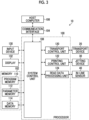
- Fig. 3 is a functional block diagram of the ink jet printing device shown in Fig. 1 .
- the ink jet printing device 10 comprises one or more processors 100 and one or more memories 102.
- the ink jet printing device 10 comprises a communication interface 104.
- the ink jet printing device 10 acquires print data and the like from an external device, such as a host computer 106, via the communication interface 104.
- the memory 102 comprises a program memory 110, a parameter memory 112, and a data memory 114.
- the program memory 110 stores various programs including instructions that can be executed by using the processor 100.
- the parameter memory 112 stores various parameters necessary for program execution.
- the data memory 114 stores various data.
- the data memory 114 may include a transitory storage region for various data.
- the memory 102 can include a tangible computer-readable medium, such as a semiconductor memory.
- the memory 102 may include a magnetic storage device, such as a hard disk.
- the memory 102 can be composed of a plurality of storage devices and the like.
- the plurality of storage devices and the like can include a plurality of different types of storage devices and the like.
- the storage device and the like constituting the memory 102 may be divided into a plurality of storage regions.
- the processor 100 executes the program stored in the program memory 110 to realize various functions of the ink jet printing device 10.
- Various processing units shown as the components of the processor 100 correspond to various functions of the ink jet printing device 10.
- the system control unit 108 executes the program stored in the program memory 110, performs various pieces of processing of the ink jet printing device 10, and performs overall control of the ink jet printing device 10.
- the transport control unit 120 controls an operation of the transport device 20. That is, the transport control unit 120 controls the feeding of the paper P and a transport speed of the paper P. It should be noted that the term speed in the present specification can include the meaning of the speed represented using an absolute value of speed.
- a printing control unit 122 controls an ink jetting operation of the ink jet head 32 based on the print data.
- the printing control unit 122 performs image processing, such as various pieces of conversion processing, various pieces of correction processing, and pieces of halftone processing on the print data.
- the conversion processing includes conversion of the number of pixels, gradation conversion, color conversion, and the like.
- the correction processing includes density unevenness correction and non-jetting correction for suppressing the visibility of an image defect due to occurrence of a non-jetting nozzle.
- the printing control unit 122 jets water the liquid droplets of the aqueous ink of each color toward the paper P from the ink jet head 32 of each color at a timing when the paper P passes a position facing the nozzle surface of the ink jet head 32.
- a read data processing unit 124 acquires the read data, such as the test image, output from the in-line sensor 40 and analyzes the acquired read data.
- the system control unit 108 corrects the ink jet head 32 and the like based on the analysis result.
- the ink jet printing device 10 comprises an input device 130.
- the processor 100 acquires an input signal output by the input device 130.
- Various operation members such as an operation panel, a keyboard, a mouse, a touch panel, and a trackball, which receive input from a user can be applied to the input device 130.
- the input device 130 may be an appropriate combination thereof.
- the ink jet printing device 10 comprises a display 132.
- the processor 100 transmits a display signal to display 132.
- the display 132 displays information based on the acquired display signal. Status information of the ink jet printing device 10, setting information of various parameters, error information of the ink jet printing device 10, or the like can be applied to the information displayed using the display 132.
- the ink jet printing device 10 can comprise a touch panel type display, and the input device 130 and the display 132 can be integrated.
- Fig. 4 is a functional block diagram showing the printing control unit shown in Fig. 3 .
- the printing control unit 122 comprises a processor 200. It should be noted that the processor 200 may be configured as a part of the processor 100 shown in Fig. 3 or may be configured separately from the processor 100.
- Various processing units of the printing control unit 122 shown as the components of the processor 200 correspond to various functions of the printing control unit 122.
- the processor 200 executes the program stored in the program memory 110 and realizes various functions related to printing control.
- the printing control unit 122 comprises a print data acquisition unit 202.
- the print data acquisition unit 202 acquires the print data from the host computer 106 shown in Fig. 3 .
- the print data acquisition unit 202 stores the acquired print data in the data memory 114 or the like shown in Fig. 3 .
- the printing control unit 122 comprises a print data processing unit 204.
- the print data processing unit 204 performs processing, such as various pieces of conversion processing, various pieces of correction processing, and pieces of halftone processing on the print data to generate a halftone image for each ink color.
- the printing control unit 122 comprises a driving voltage generation unit 206.
- the driving voltage generation unit 206 generates the driving voltage supplied to the ink jet head 32 based on the halftone image.
- the driving voltage generation unit 206 acquires the driving waveform applied to the driving voltage via a driving waveform data acquisition unit 207.
- Acquisition includes an aspect of reading out acquisition target data from a memory in which the acquisition target data is stored. Acquisition can include an aspect of generating the acquisition target data.
- the driving voltage generation unit 206 defines a correlation between the driving voltage and the jetting amount.
- the driving voltage in the correlation between the driving voltage and the jetting amount is a potential difference between the maximum potential and the reference potential.
- the driving voltage is a height at which the driving waveform is triangular or trapezoidal.
- a table format or the like is applied to the correlation between the driving voltage and the jetting amount, and is stored.
- the printing control unit 122 comprises a driving voltage adjustment unit 208.
- the driving voltage adjustment unit 208 adjusts the driving voltage supplied to the ink jet head 32 for each head module 34 shown in Fig. 2 .
- the printing control unit 122 sets the correlation between the driving voltage and the jetting amount for each head module 34.
- a common driving voltage for each head module 34 is supplied to a plurality of pressure generation elements provided in the head module 34.
- the printing control unit 122 comprises a driving voltage output unit 210.
- An electric circuit that power-amplifies the driving voltage is applied to the driving voltage output unit 210.
- the driving voltage output from the driving voltage output unit 210 is supplied to the ink jet head 32.
- the ink jet head 32 jets the ink liquid droplets toward the paper P from the nozzle opening in accordance with the driving voltage output from the driving voltage output unit 210. A color image is printed on the paper P.
- the printing control unit 122 comprises an ink information acquisition unit 214.
- the ink information acquisition unit 214 acquires ink identification information for identifying the ink applied to printing.
- the ink information acquisition unit 214 acquires ink characteristic information that represents an ink characteristic corresponding to the ink identification information.
- the ink identification information a product name and a model that represents the type of ink are applied.
- the ink characteristic information include a rate of change of a voltage coefficient derived from a measurement result of the jetting amount measurement in the shipment inspection.
- Other examples of the ink characteristic information include a ratio between the viscosity of the ink applied to printing and the viscosity of ink applied to the shipment inspection.
- the jetting amount is a volume of the ink liquid droplet jetted in a unit period.
- the voltage coefficient is applied to correct the correlation between the driving voltage and the jetting amount.
- the driving voltage corresponding to a target jetting amount is defined based on the correlation between the driving voltage and the jetting amount.
- the voltage coefficient is set for each head module 34 to adjust the driving voltage corresponding to the target jetting amount.
- the target jetting amount means a designed jetting amount corresponding to any driving voltage.
- the printing control unit 122 comprises a shipment inspection value acquisition unit 216.
- the shipment inspection includes an inspection of the jetting characteristic for each head module 34 in the ink jet head 32.
- a shipment inspection value is derived for a defined inspection item.
- the shipment inspection value is stored in the memory 102 shown in Fig. 3 .
- Examples of the shipment inspection value include the voltage coefficient in the ink applied to shipment inspection.
- An aspect in which a reference is 100%, a value exceeding 100% represents an increase in the driving voltage, and a value less than 100% represents a decrease in the driving voltage can be applied to the voltage coefficient.
- the voltage coefficient can be derived based on a result of the jetting amount measurement.
- the voltage coefficient can be derived based on the electrical characteristic, such as the electrostatic capacity of the piezoelectric element, and the mechanical characteristic, such as an amount of displacement of the piezoelectric element.
- the voltage coefficient is increased in accordance with an increase in an electrical characteristic value of the piezoelectric element and a mechanical characteristic value of the piezoelectric element.
- the voltage coefficient is decreased in accordance with the decrease of the electrical characteristic value of the piezoelectric element and the mechanical characteristic value of the piezoelectric element.
- the voltage coefficient can be derived based on a density measurement value of the printed image and a measurement value of the component of the printed image.
- Examples of the measurement value of the component of the printed image include a width of a line that constitutes the printed image and a diameter of a dot that constitutes the printed image.
- the jetting amount can be derived based on the measurement value in the printed image, and the voltage coefficient can be derived based on the derived jetting amount.
- the voltage coefficient of the shipment inspection value described in the embodiment is an example of a module characteristic and an example of an initial voltage coefficient.
- the printing control unit 122 comprises a correction coefficient setting unit 218.
- the correction coefficient setting unit 218 derives a voltage correction amount derived during the shipment inspection, and a correction coefficient that is a rate at which a voltage correction value varies in a case in which the ink applied to printing is used.
- the correction coefficient setting unit 218 sets the correction coefficient applied to correct the voltage coefficient due to the difference in the ink.
- a ratio between the voltage coefficient derived using the jetting amount measurement value of the ink applied to printing and the voltage coefficient obtained as the shipment inspection value can be applied to the correction coefficient.
- the jetting amount measurement value of the ink applied to printing can be acquired before printing by a device other than the ink jet printing device 10, such as an inspection device.
- the correction coefficient can be derived based on the viscosity of the ink applied to printing. There is concern that the accuracy of the correction coefficient derived based on the viscosity of the ink is less than that of the correction coefficient derived based on the result of the jetting amount measurement, but it is effective in a case in which the correction coefficient cannot be acquired before printing.
- the driving voltage adjustment unit 208 corrects the voltage coefficient for each head module 34 by applying the correction coefficient in the ink applied to printing to the voltage coefficient acquired as the shipment inspection value.
- a ratio between the voltage coefficient of the ink applied to printing and the voltage coefficient of the shipment inspection value may be applied, and a difference between the voltage coefficient in the ink applied to printing and the voltage coefficient of the shipment inspection value may be applied.
- the driving voltage adjustment unit 208 adjusts the driving voltage by applying the voltage coefficient corrected in accordance with the ink applied to printing.
- the driving voltage output unit 210 outputs the driving voltage adjusted in accordance with the ink applied to printing. It should be noted that the printing control unit 122 described in the embodiment is an example of a driving voltage supply device.
- Fig. 5 is a table showing an example of a voltage coefficient applied to a driving voltage adjustment method according to the first embodiment.
- the voltage coefficient shown in Fig. 5 is represented by applying percentages based on 100.
- a voltage coefficient a is the shipment inspection value.
- a correction coefficient b represents the difference between the voltage coefficient in the ink applied to printing and the voltage coefficient of the shipment inspection value.
- the ratio between the voltage coefficient in the ink applied to printing and the voltage coefficient of the shipment inspection value may be applied to the correction coefficient b.
- the voltage coefficient in the ink applied to printing is represented by a*b. * represents a difference or a ratio.
- the driving voltage corresponding to the target jetting amount is adjusted to 104% with respect to the designed driving voltage.
- the voltage coefficient in the ink applied to printing described in the embodiment is an example of a first voltage coefficient.
- processors can be applied to the hardware of a processing unit that performs the various pieces of processing shown in Figs. 3 and 4 . It should be noted that the processing unit may be referred to as a processing unit.
- the various processors include a central processing unit (CPU), a programmable logic device (PLD), an application specific integrated circuit (ASIC), and the like.
- the CPU is a general-purpose processor that executes the program to function as various processing units.
- the PLD is a processor of which a circuit configuration can be changed after manufacturing. Examples of the PLD include a field programmable gate array (FPGA).
- the ASIC is a dedicated electric circuit having a circuit configuration specifically designed to perform specific processing.
- One processing unit may be composed of one of these various processors, or may be composed of two or more processors of the same type or different types.
- one processing unit may be composed of a plurality of FPGAs and the like.
- One processing unit may be composed of a combination of one or more FPGAs and one or more CPUs.
- a plurality of processing units may be composed of one processor.
- the plurality of processing units are composed of one processor
- Such a form is represented by a computer, such as a client terminal device and a server device.
- a processor that realizes entire functions of a system including the plurality of processing units using one IC chip is used.
- a system on chip Such a form is represented by a system on chip.
- IC is an abbreviation of an integrated circuit.
- the system on chip may be described as SoC using an abbreviation of system on chip.
- the various processing units are composed of one or more of the various processors described above as the hardware structure.
- the hardware structure of the various processors is an electric circuit (circuitry) in which circuit elements, such as semiconductor elements, are combined.
- Fig. 6 is a flowchart showing a procedure of the driving voltage adjustment method according to the first embodiment.
- shipment inspection value acquisition step S10 the shipment inspection value acquisition unit 216 shown in Fig. 3 acquires the shipment inspection value for each head module 34.
- the shipment inspection value may be acquired from an external device or the like via the communication interface 104 shown in Fig. 2 , or the shipment inspection value stored inside the ink jet printing device 10 may be read out.
- shipment inspection value acquisition step S10 the processing proceeds to ink information acquisition step S12.
- ink information acquisition step S12 the ink information acquisition unit 214 acquires the ink characteristic information that represents the ink characteristic of the ink applied to printing. After ink information acquisition step S12, the processing proceeds to correction coefficient setting step S14.
- correction coefficient setting step S14 the correction coefficient setting unit 218 sets the correction coefficient in accordance with the ink applied to printing.
- Correction coefficient setting step S14 can include a correction coefficient acquisition step of acquiring the correction coefficient.
- Correction coefficient setting step S14 can include a correction coefficient derivation step of deriving the correction coefficient. After correction coefficient setting step S14, the processing proceeds to voltage coefficient correction step S16.
- the driving voltage adjustment unit 208 corrects the voltage coefficient of the shipment inspection value by applying the correction coefficient corresponding to the ink applied to printing, and derives the voltage coefficient corresponding to the ink applied to printing. After voltage coefficient correction step S16, the processing proceeds to driving voltage adjustment step S18.
- driving voltage adjustment unit 208 adjusts the driving voltage for each head module 34 by applying the voltage coefficient corresponding to the ink applied to printing for each head module 34. After driving voltage adjustment step S18, the processing proceeds to driving voltage output step S20.
- driving voltage output step S20 the driving voltage output unit 210 outputs the driving voltage adjusted for each head module 34 in driving voltage adjustment step S18.
- Fig. 7 is a conceptual diagram of the jetting characteristic for each module.
- a graph format is used to show a difference in the jetting amount in a case in which the driving voltage before adjustment using the voltage coefficient is supplied to the plurality of head modules 34.
- a horizontal axis represents a position of the head module 34.
- a vertical axis represents the jetting amount.
- the jetting amount is measured for each head module 34, and the voltage coefficient is derived for each head module 34 based on the result of the jetting amount measurement.
- the target jetting amount is realized in a case in which the driving voltage adjusted using the voltage coefficient of the shipment inspection value is applied.
- Fig. 8 is a conceptual diagram of the jetting characteristic of the ink applied to printing for each head module.
- Fig. 8 shows an example of the jetting characteristic for each module in a case in which the ink applied to printing is different from the ink applied for the jetting amount measurement in the shipment inspection.
- the actual jetting amount for each head module 34 is different from the target jetting amount due to the different in the ink characteristic, such as the viscosity of the ink. Therefore, the voltage coefficient is corrected for each head module 34 based on the ink characteristic of the ink applied to printing, and the driving voltage is adjusted using the corrected voltage coefficient. As a result, the target jetting amount is realized for all the head modules 34.
- the ink jet printing device 10 and the driving voltage adjustment method according to the first embodiment can obtain the following action and effect.
- Fig. 9 is a functional block diagram of a printing control unit applied to an ink jet printing device according to a second embodiment.
- the ink jet printing device according to the second embodiment performs the density measurement of the printed image using the driving voltage adjusted based on the voltage coefficient corresponding to the ink applied to printing, and corrects the voltage coefficient for each head module 34 based on the density measurement value of the printed image.
- a processor 200A constituting a printing control unit 122A shown in Fig. 9 includes a density measurement data processing unit 220 added to the processor 200 shown in Fig. 4 .
- the density measurement data processing unit 220 acquires the read data of the printed image for each head module 34 from the in-line sensor 40.
- the density measurement data processing unit 220 derives the density measurement value of the printed image for each head module 34 based on the read data of the printed image.
- the correction coefficient setting unit 218 derives the voltage coefficient that realizes a defined target density value for each head module 34.
- An average value of the density measurement values in two or more head modules 34 can be applied to the target density value.
- the density measurement value in any one head module 34 may be applied to the target density value.
- the density measurement data processing unit 220 may derive the correlation between the voltage coefficient and the density value based on the read data of a plurality of density measurement charts printed with different voltage coefficients.
- the correction coefficient setting unit 218 can derive the voltage coefficient corresponding to the target density value using the correlation between the voltage coefficient and the density value.
- the ink jet printing device derives the voltage coefficient subjected to the relative density adjustment, applies the voltage coefficient subjected to the relative density adjustment, and adjusts the driving voltage.
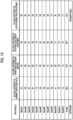
- Fig. 10 is a table showing an example of a voltage coefficient applied to a driving voltage adjustment method according to the second embodiment.
- the values in a column of the voltage coefficient of the shipment inspection value and the values in a column of the voltage coefficient of the correction coefficient addition are the same as those in the table shown in Fig. 5 .
- the description thereof will be omitted.
- the correction coefficient setting unit 218 shown in Fig. 9 derives and sets a voltage coefficient c after the relative density adjustment shown in Fig. 10 .
- the correlation between the voltage coefficient and the density value derived by irregularly increasing or decreasing the voltage coefficient for each head module 34 is applied to the voltage coefficient c shown in Fig. 9 .
- the correction coefficient setting unit 218 derives the voltage coefficient after the average value adjustment by multiplying the voltage coefficient c after the relative density adjustment for each head module 34 by the ratio between the average value of the voltage coefficients before the relative density adjustment and the average value of the voltage coefficients after the relative density adjustment.
- the voltage coefficient after the average value adjustment is represented by c ⁇ ⁇ Avg(a*b)/Avg(c) ⁇ . It should be noted that Avg represents an average value of the values in parentheses for the plurality of head modules 34.
- a numerical value in a column of Average shown in Fig. 10 represents an average value of the voltage coefficients in the plurality of head modules 34.
- the voltage coefficient after the average value adjustment is derived in which the ratio between the voltage coefficient a in the shipment inspection value and the voltage coefficient in the ink jet printing device 10 applied to printing is maintained.
- Fig. 11 is a conceptual diagram of the relative density adjustment and the average value adjustment.
- the density measurement value for each head module 34 is schematically shown using a graph format.
- a horizontal axis of the graph shown in Fig. 11 represents the position of the head module 34.
- a vertical axis represents the density measurement value.
- the density measurement value for each head module 34 is different from the target density value.
- the density measurement value of the printed image for each head module 34 is matched to a target relative density value.
- a broken arrow line given to each head module 34 schematically represents the relative density adjustment.
- the density measurement value of the printed image for each head module 34 is matched to a target absolute density value.
- a solid arrow line given to each head module 34 schematically represents the relative density adjustment.
- Fig. 12 is a flowchart showing a procedure of the driving voltage adjustment method according to the second embodiment.
- Shipment inspection value acquisition step S100, ink information acquisition step S102, correction coefficient setting step S104, and voltage coefficient correction step S106 shown in Fig. 12 are the same as the steps from shipment inspection value acquisition step S10 to voltage coefficient correction step S16 shown in Fig. 6 , respectively. Here, the description thereof will be omitted.
- voltage coefficient correction step S106 the processing proceeds to density measurement value acquisition step S108.
- density measurement value acquisition step S108 the density measurement data processing unit 220 shown in Fig. 9 acquires the density measurement value for each head module 34 to which the driving voltage to which the voltage coefficient before the relative density adjustment is applied is applied. After density measurement value acquisition step S108, the processing proceeds to relative density adjusted voltage coefficient derivation step S110.
- relative density adjusted voltage coefficient derivation step S110 the correction coefficient setting unit 218 derives and sets the voltage coefficient c after the relative density adjustment based on the density measurement value acquired in density measurement value acquisition step S108. After relative density adjusted voltage coefficient derivation step S110, the processing proceeds to average value adjusted voltage coefficient derivation step S112.
- the correction coefficient setting unit 218 derives and sets the voltage coefficient after the average value adjustment shown in Fig. 10 .
- the processing proceeds to driving voltage adjustment step S114 and driving voltage output step S116.
- Driving voltage adjustment step S114 and driving voltage output step S116 are the same as driving voltage adjustment step S18 and driving voltage output step S20 shown in Fig. 6 , respectively. Here, the description thereof will be omitted.
- the voltage coefficient after the relative density adjustment described in the embodiment is an example of a second voltage coefficient.
- the voltage coefficient after the average value adjustment described in the embodiment is an example of a third voltage coefficient.
- the voltage coefficient based on the density measurement value may be derived, paper information including the type of the paper P may be acquired, and the voltage coefficient may be set in accordance with the combination of the ink and the paper P. It should be noted that the paper P described in the embodiment is an example of a medium.
- the voltage coefficient based on the density measurement value is derived in advance.
- Lot information of the paper P can be acquired as the paper information, and the voltage coefficient for each lot can be used to adjust the driving voltage, and the density unevenness of the printed image due to the variation in the lots of the paper P can be suppressed.
- the driving voltage adjustment method according to the second embodiment can obtain the following action and effect.
- Fig. 13 is an explanatory diagram of the action and the effect of the second embodiment.
- Three head modules 34 shown in 13 can be, for example, the head modules 34 described as Module#1, Module#2, and Module#3 in the table shown in Fig. 10 .
- Each of a printed image 300, a printed image 302, and a printed image 304 is printed by supplying the driving voltage adjusted by applying the voltage coefficient of the shipment inspection value to each head module 34.
- a printed image 306 including the printed image 300, the printed image 302, and the printed image 304 the density unevenness due to the ink characteristic occurs.
- a printed image 316 including a printed image 310, a printed image 312, and a printed image 314 is printed by supplying the driving voltage adjusted by applying the voltage coefficient after the relative density adjustment to each head module 34.
- the density unevenness due to the characteristic of the head module 34 is suppressed.
- the voltage coefficient after the average value adjustment is derived from the voltage coefficient after the relative density adjustment, and the driving voltage is adjusted using the voltage coefficient after the average value adjustment. As a result, the printing density of each head module 34 is set to the target absolute density.
- a printed image 320, a printed image 322, and a printed image 324 shown in Fig. 13 are printed by supplying the driving voltage adjusted by applying the voltage coefficient after the average value adjustment to each head module 34.
- a printed image 326 including the printed image 320, the printed image 322, and the printed image 324 the absolute target density is realized.
- a pretreatment liquid can be applied to the ink jet printing device 10 shown in Fig. 1 .
- the pretreatment liquid include a precoat liquid that aggregates or insolubilizes a coloring material contained in the ink.
- the ink jet printing device 10 can comprise a precoat application device that applies the precoat liquid and a precoat liquid drying device that dries the paper P coated with the precoat liquid.
- the density unevenness due to the variation in the application of the precoat liquid can occur.
- the driving voltage is adjusted using the voltage coefficient after the relative density adjustment. As a result, the printing density of each head module 34 is made uniform.
- the continuous paper can be applied to the paper P in the ink jet printing device 10 shown in Fig. 1 .
- a roll-to-roll form can be applied to the transport form of the paper P.
- a load in a case in which the paper P for ink jet printing is used is large, and the occurrence of the density unevenness of the printed image is remarkable.
- the adjustment of the driving voltage by applying the voltage coefficient based on the density measurement value of the paper P in accordance with the paper information can suppress the density unevenness of the printed image.
- the printing control unit 122 shown in Figs. 3 and 4 can be combined with the ink jet head 32 shown in Figs. 1 and 2 to constitute the head device, which is the external device of the ink jet printing device 10.
- a program corresponding to the ink jet printing device 10 and the driving voltage adjustment method can be configured. That is, it is possible to constitute the program that causes the computer to realize the functions of various processing units shown in Figs. 3 and 4 and each step shown in Figs. 6 and 11 .
- printing device is synonymous with terms, such as a printing machine, a printer, a typing device, an image recording device, an image forming device, an image output device, and a drawing device.
- the image is interpreted in a broad sense, and also includes a color image, a monochrome image, a single color image, a gradation image, a uniform density image, and the like.
- printing includes concepts of terms, such as recording the image, forming the image, typing, drawing, and printing.
- device can include the concept of a system.
- the image is not limited to a photographic image, and is used as a collective term including a design, a text, a symbol, a line drawing, a mosaic pattern, a color-coding pattern, other various patterns, and an appropriate combination thereof.
- the term image can include the meaning of an image signal and image data that represents the image.
Landscapes
- Engineering & Computer Science (AREA)
- Quality & Reliability (AREA)
- Ink Jet (AREA)
- Particle Formation And Scattering Control In Inkjet Printers (AREA)
Applications Claiming Priority (2)
| Application Number | Priority Date | Filing Date | Title |
|---|---|---|---|
| JP2020102125 | 2020-06-12 | ||
| PCT/JP2021/020926 WO2021251223A1 (ja) | 2020-06-12 | 2021-06-02 | ヘッド装置、インクジェット印刷装置及び駆動電圧調整方法 |
Publications (3)
| Publication Number | Publication Date |
|---|---|
| EP4166335A1 EP4166335A1 (en) | 2023-04-19 |
| EP4166335A4 EP4166335A4 (en) | 2023-11-08 |
| EP4166335B1 true EP4166335B1 (en) | 2025-01-22 |
Family
ID=78846046
Family Applications (1)
| Application Number | Title | Priority Date | Filing Date |
|---|---|---|---|
| EP21820945.0A Active EP4166335B1 (en) | 2020-06-12 | 2021-06-02 | Head device, inkjet printing apparatus, and method for regulating drive voltage |
Country Status (4)
| Country | Link |
|---|---|
| US (1) | US12187032B2 (https=) |
| EP (1) | EP4166335B1 (https=) |
| JP (1) | JP7350177B2 (https=) |
| WO (1) | WO2021251223A1 (https=) |
Family Cites Families (16)
| Publication number | Priority date | Publication date | Assignee | Title |
|---|---|---|---|---|
| AU577301B2 (en) | 1983-09-16 | 1988-09-22 | Kato Spring Works Company, Ltd. | Tangless helical coiled insert |
| JPH04250054A (ja) * | 1991-01-18 | 1992-09-04 | Canon Inc | インクジェット記録装置 |
| JP2003182056A (ja) * | 2001-12-18 | 2003-07-03 | Sii Printek Inc | インクジェット式記録装置 |
| JP2006198902A (ja) | 2005-01-20 | 2006-08-03 | Fuji Xerox Co Ltd | 印字装置及び印字方法 |
| JP2007210234A (ja) * | 2006-02-10 | 2007-08-23 | Seiko Epson Corp | 適正駆動電圧決定装置、及び、適正駆動電圧決定方法 |
| KR20070084890A (ko) * | 2006-02-22 | 2007-08-27 | 삼성전자주식회사 | 잉크젯 헤드의 잉크 토출 특성 조절 방법 |
| JP2008093853A (ja) * | 2006-10-06 | 2008-04-24 | Canon Inc | インクジェット記録装置およびインクジェット記録方法 |
| JP5106173B2 (ja) * | 2008-02-22 | 2012-12-26 | 理想科学工業株式会社 | 印刷装置および印刷処理方法 |
| JP5293245B2 (ja) * | 2009-02-10 | 2013-09-18 | セイコーエプソン株式会社 | 流体噴射装置のヘッドの駆動パルス設定方法 |
| JP5680362B2 (ja) * | 2010-10-01 | 2015-03-04 | 富士フイルム株式会社 | インクジェット記録装置及び方法 |
| JP5760918B2 (ja) * | 2011-09-30 | 2015-08-12 | ブラザー工業株式会社 | 液体吐出装置 |
| JP6042295B2 (ja) | 2013-09-04 | 2016-12-14 | 富士フイルム株式会社 | 記録ヘッド及びその製造方法並びに記録装置 |
| JP6561645B2 (ja) | 2015-07-10 | 2019-08-21 | 株式会社リコー | 液滴吐出装置、画像形成装置、液滴吐出装置の制御方法、及びプログラム |
| CN108025550B (zh) | 2015-09-17 | 2020-01-07 | 柯尼卡美能达株式会社 | 喷墨记录装置以及喷墨记录装置的排墨调整方法 |
| JP2019205974A (ja) | 2018-05-29 | 2019-12-05 | キヤノン株式会社 | インクジェット装置、およびそれを用いた機能素子の製造方法 |
| JP2019217649A (ja) | 2018-06-18 | 2019-12-26 | セイコーエプソン株式会社 | 液体吐出装置および駆動回路 |
-
2021
- 2021-06-02 EP EP21820945.0A patent/EP4166335B1/en active Active
- 2021-06-02 WO PCT/JP2021/020926 patent/WO2021251223A1/ja not_active Ceased
- 2021-06-02 JP JP2022530494A patent/JP7350177B2/ja active Active
-
2022
- 2022-11-29 US US18/059,568 patent/US12187032B2/en active Active
Also Published As
| Publication number | Publication date |
|---|---|
| US20230097719A1 (en) | 2023-03-30 |
| JPWO2021251223A1 (https=) | 2021-12-16 |
| JP7350177B2 (ja) | 2023-09-25 |
| US12187032B2 (en) | 2025-01-07 |
| WO2021251223A1 (ja) | 2021-12-16 |
| EP4166335A4 (en) | 2023-11-08 |
| EP4166335A1 (en) | 2023-04-19 |
Similar Documents
| Publication | Publication Date | Title |
|---|---|---|
| US8733877B2 (en) | Method and apparatus for detecting discharge defect, image processing apparatus, computer-readable recording medium, and printing system | |
| US11820133B2 (en) | Image processing method, apparatus, program, and image forming apparatus | |
| US8967750B2 (en) | Inkjet recording apparatus and image recording method | |
| JP6005616B2 (ja) | インクジェットヘッドの補正方法及びインクジェット記録装置 | |
| US9227394B2 (en) | Head adjustment method, head-driving device and image-forming device | |
| JP2011173324A (ja) | 画像記録装置及び画像記録装置のヘッド調整方法 | |
| JP5952704B2 (ja) | ヘッド駆動方法、ヘッド駆動装置およびインクジェット記録装置 | |
| JP2012250472A (ja) | インクジェット記録ヘッドの状態監視装置及びインクジェット記録装置 | |
| JP5894046B2 (ja) | 画像処理方法、画像処理装置、画像処理プログラム及び画像記録装置 | |
| US20080259108A1 (en) | Ink ejection amount measurement method and ink ejection amount measurement system | |
| WO2018225489A1 (ja) | 画像形成装置及びその制御方法 | |
| EP4166335B1 (en) | Head device, inkjet printing apparatus, and method for regulating drive voltage | |
| US20110216115A1 (en) | Printing method and printing apparatus | |
| JP2011218560A (ja) | 濃度補正方法、及び、印刷装置 | |
| JP2009137251A (ja) | 液体吐出方法、及び液体吐出装置 | |
| JP5213615B2 (ja) | 画像形成装置および画像形成方法 | |
| JP7732852B2 (ja) | 記録ヘッドの制御装置及び制御方法、印刷装置 | |
| JP6878157B2 (ja) | 液滴吐出ヘッドの製造方法、画像形成装置の製造方法、液滴吐出ヘッド及び画像形成装置 | |
| JP6257550B2 (ja) | 吐出異常検出方法、液体吐出装置、及び吐出異常検出プログラム | |
| JP7765248B2 (ja) | 画像処理方法、画像処理装置、プログラム及び画像形成装置 | |
| JP7630408B2 (ja) | 画像記録方法及び画像記録装置 | |
| JP2010194754A (ja) | 流体噴射装置の製造方法 | |
| JP2010201639A (ja) | 流体噴射装置の製造方法 | |
| JP6584998B2 (ja) | 液体吐出装置、及び短絡検出方法 | |
| JP2010269470A (ja) | 補正値設定方法、及び、流体噴射装置の製造方法 |
Legal Events
| Date | Code | Title | Description |
|---|---|---|---|
| STAA | Information on the status of an ep patent application or granted ep patent |
Free format text: STATUS: THE INTERNATIONAL PUBLICATION HAS BEEN MADE |
|
| PUAI | Public reference made under article 153(3) epc to a published international application that has entered the european phase |
Free format text: ORIGINAL CODE: 0009012 |
|
| STAA | Information on the status of an ep patent application or granted ep patent |
Free format text: STATUS: REQUEST FOR EXAMINATION WAS MADE |
|
| 17P | Request for examination filed |
Effective date: 20221130 |
|
| AK | Designated contracting states |
Kind code of ref document: A1 Designated state(s): AL AT BE BG CH CY CZ DE DK EE ES FI FR GB GR HR HU IE IS IT LI LT LU LV MC MK MT NL NO PL PT RO RS SE SI SK SM TR |
|
| DAV | Request for validation of the european patent (deleted) | ||
| DAX | Request for extension of the european patent (deleted) | ||
| A4 | Supplementary search report drawn up and despatched |
Effective date: 20231010 |
|
| RIC1 | Information provided on ipc code assigned before grant |
Ipc: B41J 25/00 20060101ALI20231004BHEP Ipc: B41J 2/21 20060101ALI20231004BHEP Ipc: B41J 2/045 20060101ALI20231004BHEP Ipc: B41J 2/01 20060101ALI20231004BHEP Ipc: B41J 2/015 20060101AFI20231004BHEP |
|
| GRAP | Despatch of communication of intention to grant a patent |
Free format text: ORIGINAL CODE: EPIDOSNIGR1 |
|
| STAA | Information on the status of an ep patent application or granted ep patent |
Free format text: STATUS: GRANT OF PATENT IS INTENDED |
|
| INTG | Intention to grant announced |
Effective date: 20240816 |
|
| GRAS | Grant fee paid |
Free format text: ORIGINAL CODE: EPIDOSNIGR3 |
|
| GRAA | (expected) grant |
Free format text: ORIGINAL CODE: 0009210 |
|
| STAA | Information on the status of an ep patent application or granted ep patent |
Free format text: STATUS: THE PATENT HAS BEEN GRANTED |
|
| AK | Designated contracting states |
Kind code of ref document: B1 Designated state(s): AL AT BE BG CH CY CZ DE DK EE ES FI FR GB GR HR HU IE IS IT LI LT LU LV MC MK MT NL NO PL PT RO RS SE SI SK SM TR |
|
| REG | Reference to a national code |
Ref country code: GB Ref legal event code: FG4D |
|
| REG | Reference to a national code |
Ref country code: CH Ref legal event code: EP |
|
| REG | Reference to a national code |
Ref country code: IE Ref legal event code: FG4D |
|
| REG | Reference to a national code |
Ref country code: DE Ref legal event code: R096 Ref document number: 602021025193 Country of ref document: DE |
|
| REG | Reference to a national code |
Ref country code: NL Ref legal event code: MP Effective date: 20250122 |
|
| PG25 | Lapsed in a contracting state [announced via postgrant information from national office to epo] |
Ref country code: NL Free format text: LAPSE BECAUSE OF FAILURE TO SUBMIT A TRANSLATION OF THE DESCRIPTION OR TO PAY THE FEE WITHIN THE PRESCRIBED TIME-LIMIT Effective date: 20250122 |
|
| PG25 | Lapsed in a contracting state [announced via postgrant information from national office to epo] |
Ref country code: RS Free format text: LAPSE BECAUSE OF FAILURE TO SUBMIT A TRANSLATION OF THE DESCRIPTION OR TO PAY THE FEE WITHIN THE PRESCRIBED TIME-LIMIT Effective date: 20250422 |
|
| PG25 | Lapsed in a contracting state [announced via postgrant information from national office to epo] |
Ref country code: FI Free format text: LAPSE BECAUSE OF FAILURE TO SUBMIT A TRANSLATION OF THE DESCRIPTION OR TO PAY THE FEE WITHIN THE PRESCRIBED TIME-LIMIT Effective date: 20250122 |
|
| PG25 | Lapsed in a contracting state [announced via postgrant information from national office to epo] |
Ref country code: PL Free format text: LAPSE BECAUSE OF FAILURE TO SUBMIT A TRANSLATION OF THE DESCRIPTION OR TO PAY THE FEE WITHIN THE PRESCRIBED TIME-LIMIT Effective date: 20250122 |
|
| PGFP | Annual fee paid to national office [announced via postgrant information from national office to epo] |
Ref country code: DE Payment date: 20250429 Year of fee payment: 5 |
|
| PG25 | Lapsed in a contracting state [announced via postgrant information from national office to epo] |
Ref country code: ES Free format text: LAPSE BECAUSE OF FAILURE TO SUBMIT A TRANSLATION OF THE DESCRIPTION OR TO PAY THE FEE WITHIN THE PRESCRIBED TIME-LIMIT Effective date: 20250122 |
|
| REG | Reference to a national code |
Ref country code: LT Ref legal event code: MG9D |
|
| PG25 | Lapsed in a contracting state [announced via postgrant information from national office to epo] |
Ref country code: NO Free format text: LAPSE BECAUSE OF FAILURE TO SUBMIT A TRANSLATION OF THE DESCRIPTION OR TO PAY THE FEE WITHIN THE PRESCRIBED TIME-LIMIT Effective date: 20250422 Ref country code: IS Free format text: LAPSE BECAUSE OF FAILURE TO SUBMIT A TRANSLATION OF THE DESCRIPTION OR TO PAY THE FEE WITHIN THE PRESCRIBED TIME-LIMIT Effective date: 20250522 |
|
| REG | Reference to a national code |
Ref country code: AT Ref legal event code: MK05 Ref document number: 1761189 Country of ref document: AT Kind code of ref document: T Effective date: 20250122 |
|
| PG25 | Lapsed in a contracting state [announced via postgrant information from national office to epo] |
Ref country code: HR Free format text: LAPSE BECAUSE OF FAILURE TO SUBMIT A TRANSLATION OF THE DESCRIPTION OR TO PAY THE FEE WITHIN THE PRESCRIBED TIME-LIMIT Effective date: 20250122 |
|
| PG25 | Lapsed in a contracting state [announced via postgrant information from national office to epo] |
Ref country code: PT Free format text: LAPSE BECAUSE OF FAILURE TO SUBMIT A TRANSLATION OF THE DESCRIPTION OR TO PAY THE FEE WITHIN THE PRESCRIBED TIME-LIMIT Effective date: 20250522 Ref country code: LV Free format text: LAPSE BECAUSE OF FAILURE TO SUBMIT A TRANSLATION OF THE DESCRIPTION OR TO PAY THE FEE WITHIN THE PRESCRIBED TIME-LIMIT Effective date: 20250122 |
|
| PG25 | Lapsed in a contracting state [announced via postgrant information from national office to epo] |
Ref country code: BG Free format text: LAPSE BECAUSE OF FAILURE TO SUBMIT A TRANSLATION OF THE DESCRIPTION OR TO PAY THE FEE WITHIN THE PRESCRIBED TIME-LIMIT Effective date: 20250122 Ref country code: GR Free format text: LAPSE BECAUSE OF FAILURE TO SUBMIT A TRANSLATION OF THE DESCRIPTION OR TO PAY THE FEE WITHIN THE PRESCRIBED TIME-LIMIT Effective date: 20250423 |
|
| PG25 | Lapsed in a contracting state [announced via postgrant information from national office to epo] |
Ref country code: AT Free format text: LAPSE BECAUSE OF FAILURE TO SUBMIT A TRANSLATION OF THE DESCRIPTION OR TO PAY THE FEE WITHIN THE PRESCRIBED TIME-LIMIT Effective date: 20250122 |
|
| PG25 | Lapsed in a contracting state [announced via postgrant information from national office to epo] |
Ref country code: SE Free format text: LAPSE BECAUSE OF FAILURE TO SUBMIT A TRANSLATION OF THE DESCRIPTION OR TO PAY THE FEE WITHIN THE PRESCRIBED TIME-LIMIT Effective date: 20250122 |
|
| PG25 | Lapsed in a contracting state [announced via postgrant information from national office to epo] |
Ref country code: SM Free format text: LAPSE BECAUSE OF FAILURE TO SUBMIT A TRANSLATION OF THE DESCRIPTION OR TO PAY THE FEE WITHIN THE PRESCRIBED TIME-LIMIT Effective date: 20250122 |
|
| PG25 | Lapsed in a contracting state [announced via postgrant information from national office to epo] |
Ref country code: DK Free format text: LAPSE BECAUSE OF FAILURE TO SUBMIT A TRANSLATION OF THE DESCRIPTION OR TO PAY THE FEE WITHIN THE PRESCRIBED TIME-LIMIT Effective date: 20250122 |
|
| PG25 | Lapsed in a contracting state [announced via postgrant information from national office to epo] |
Ref country code: IT Free format text: LAPSE BECAUSE OF FAILURE TO SUBMIT A TRANSLATION OF THE DESCRIPTION OR TO PAY THE FEE WITHIN THE PRESCRIBED TIME-LIMIT Effective date: 20250122 |
|
| PG25 | Lapsed in a contracting state [announced via postgrant information from national office to epo] |
Ref country code: CZ Free format text: LAPSE BECAUSE OF FAILURE TO SUBMIT A TRANSLATION OF THE DESCRIPTION OR TO PAY THE FEE WITHIN THE PRESCRIBED TIME-LIMIT Effective date: 20250122 Ref country code: EE Free format text: LAPSE BECAUSE OF FAILURE TO SUBMIT A TRANSLATION OF THE DESCRIPTION OR TO PAY THE FEE WITHIN THE PRESCRIBED TIME-LIMIT Effective date: 20250122 |
|
| REG | Reference to a national code |
Ref country code: DE Ref legal event code: R097 Ref document number: 602021025193 Country of ref document: DE |
|
| PG25 | Lapsed in a contracting state [announced via postgrant information from national office to epo] |
Ref country code: RO Free format text: LAPSE BECAUSE OF FAILURE TO SUBMIT A TRANSLATION OF THE DESCRIPTION OR TO PAY THE FEE WITHIN THE PRESCRIBED TIME-LIMIT Effective date: 20250122 |
|
| PG25 | Lapsed in a contracting state [announced via postgrant information from national office to epo] |
Ref country code: SK Free format text: LAPSE BECAUSE OF FAILURE TO SUBMIT A TRANSLATION OF THE DESCRIPTION OR TO PAY THE FEE WITHIN THE PRESCRIBED TIME-LIMIT Effective date: 20250122 |
|
| PLBE | No opposition filed within time limit |
Free format text: ORIGINAL CODE: 0009261 |
|
| STAA | Information on the status of an ep patent application or granted ep patent |
Free format text: STATUS: NO OPPOSITION FILED WITHIN TIME LIMIT |
|
| REG | Reference to a national code |
Ref country code: CH Ref legal event code: L10 Free format text: ST27 STATUS EVENT CODE: U-0-0-L10-L00 (AS PROVIDED BY THE NATIONAL OFFICE) Effective date: 20251203 |
|
| 26N | No opposition filed |
Effective date: 20251023 |
|
| REG | Reference to a national code |
Ref country code: CH Ref legal event code: H13 Free format text: ST27 STATUS EVENT CODE: U-0-0-H10-H13 (AS PROVIDED BY THE NATIONAL OFFICE) Effective date: 20260127 |
|
| PG25 | Lapsed in a contracting state [announced via postgrant information from national office to epo] |
Ref country code: MC Free format text: LAPSE BECAUSE OF FAILURE TO SUBMIT A TRANSLATION OF THE DESCRIPTION OR TO PAY THE FEE WITHIN THE PRESCRIBED TIME-LIMIT Effective date: 20250122 |
|
| PG25 | Lapsed in a contracting state [announced via postgrant information from national office to epo] |
Ref country code: LU Free format text: LAPSE BECAUSE OF NON-PAYMENT OF DUE FEES Effective date: 20250602 |
|
| GBPC | Gb: european patent ceased through non-payment of renewal fee |
Effective date: 20250602 |
|
| REG | Reference to a national code |
Ref country code: BE Ref legal event code: MM Effective date: 20250630 |
|
| PG25 | Lapsed in a contracting state [announced via postgrant information from national office to epo] |
Ref country code: GB Free format text: LAPSE BECAUSE OF NON-PAYMENT OF DUE FEES Effective date: 20250602 |
|
| PG25 | Lapsed in a contracting state [announced via postgrant information from national office to epo] |
Ref country code: IE Free format text: LAPSE BECAUSE OF NON-PAYMENT OF DUE FEES Effective date: 20250602 |
|
| PG25 | Lapsed in a contracting state [announced via postgrant information from national office to epo] |
Ref country code: BE Free format text: LAPSE BECAUSE OF NON-PAYMENT OF DUE FEES Effective date: 20250630 |
|
| PG25 | Lapsed in a contracting state [announced via postgrant information from national office to epo] |
Ref country code: FR Free format text: LAPSE BECAUSE OF NON-PAYMENT OF DUE FEES Effective date: 20250630 |
|
| PG25 | Lapsed in a contracting state [announced via postgrant information from national office to epo] |
Ref country code: CH Free format text: LAPSE BECAUSE OF NON-PAYMENT OF DUE FEES Effective date: 20250630 |