WO2021251223A1 - ヘッド装置、インクジェット印刷装置及び駆動電圧調整方法 - Google Patents
ヘッド装置、インクジェット印刷装置及び駆動電圧調整方法 Download PDFInfo
- Publication number
- WO2021251223A1 WO2021251223A1 PCT/JP2021/020926 JP2021020926W WO2021251223A1 WO 2021251223 A1 WO2021251223 A1 WO 2021251223A1 JP 2021020926 W JP2021020926 W JP 2021020926W WO 2021251223 A1 WO2021251223 A1 WO 2021251223A1
- Authority
- WO
- WIPO (PCT)
- Prior art keywords
- head
- ink
- drive voltage
- voltage
- module
- Prior art date
- Legal status (The legal status is an assumption and is not a legal conclusion. Google has not performed a legal analysis and makes no representation as to the accuracy of the status listed.)
- Ceased
Links
Images



Classifications
-
- B—PERFORMING OPERATIONS; TRANSPORTING
- B41—PRINTING; LINING MACHINES; TYPEWRITERS; STAMPS
- B41J—TYPEWRITERS; SELECTIVE PRINTING MECHANISMS, i.e. MECHANISMS PRINTING OTHERWISE THAN FROM A FORME; CORRECTION OF TYPOGRAPHICAL ERRORS
- B41J2/00—Typewriters or selective printing mechanisms characterised by the printing or marking process for which they are designed
- B41J2/005—Typewriters or selective printing mechanisms characterised by the printing or marking process for which they are designed characterised by bringing liquid or particles selectively into contact with a printing material
- B41J2/01—Ink jet
- B41J2/015—Ink jet characterised by the jet generation process
- B41J2/04—Ink jet characterised by the jet generation process generating single droplets or particles on demand
- B41J2/045—Ink jet characterised by the jet generation process generating single droplets or particles on demand by pressure, e.g. electromechanical transducers
- B41J2/04501—Control methods or devices therefor, e.g. driver circuits, control circuits
- B41J2/04581—Control methods or devices therefor, e.g. driver circuits, control circuits controlling heads based on piezoelectric elements
-
- B—PERFORMING OPERATIONS; TRANSPORTING
- B41—PRINTING; LINING MACHINES; TYPEWRITERS; STAMPS
- B41J—TYPEWRITERS; SELECTIVE PRINTING MECHANISMS, i.e. MECHANISMS PRINTING OTHERWISE THAN FROM A FORME; CORRECTION OF TYPOGRAPHICAL ERRORS
- B41J2/00—Typewriters or selective printing mechanisms characterised by the printing or marking process for which they are designed
- B41J2/005—Typewriters or selective printing mechanisms characterised by the printing or marking process for which they are designed characterised by bringing liquid or particles selectively into contact with a printing material
- B41J2/01—Ink jet
- B41J2/015—Ink jet characterised by the jet generation process
- B41J2/04—Ink jet characterised by the jet generation process generating single droplets or particles on demand
- B41J2/045—Ink jet characterised by the jet generation process generating single droplets or particles on demand by pressure, e.g. electromechanical transducers
- B41J2/04501—Control methods or devices therefor, e.g. driver circuits, control circuits
- B41J2/04508—Control methods or devices therefor, e.g. driver circuits, control circuits aiming at correcting other parameters
-
- B—PERFORMING OPERATIONS; TRANSPORTING
- B41—PRINTING; LINING MACHINES; TYPEWRITERS; STAMPS
- B41J—TYPEWRITERS; SELECTIVE PRINTING MECHANISMS, i.e. MECHANISMS PRINTING OTHERWISE THAN FROM A FORME; CORRECTION OF TYPOGRAPHICAL ERRORS
- B41J2/00—Typewriters or selective printing mechanisms characterised by the printing or marking process for which they are designed
- B41J2/005—Typewriters or selective printing mechanisms characterised by the printing or marking process for which they are designed characterised by bringing liquid or particles selectively into contact with a printing material
- B41J2/01—Ink jet
- B41J2/015—Ink jet characterised by the jet generation process
- B41J2/04—Ink jet characterised by the jet generation process generating single droplets or particles on demand
- B41J2/045—Ink jet characterised by the jet generation process generating single droplets or particles on demand by pressure, e.g. electromechanical transducers
- B41J2/04501—Control methods or devices therefor, e.g. driver circuits, control circuits
- B41J2/04541—Specific driving circuit
-
- B—PERFORMING OPERATIONS; TRANSPORTING
- B41—PRINTING; LINING MACHINES; TYPEWRITERS; STAMPS
- B41J—TYPEWRITERS; SELECTIVE PRINTING MECHANISMS, i.e. MECHANISMS PRINTING OTHERWISE THAN FROM A FORME; CORRECTION OF TYPOGRAPHICAL ERRORS
- B41J2/00—Typewriters or selective printing mechanisms characterised by the printing or marking process for which they are designed
- B41J2/005—Typewriters or selective printing mechanisms characterised by the printing or marking process for which they are designed characterised by bringing liquid or particles selectively into contact with a printing material
- B41J2/01—Ink jet
- B41J2/015—Ink jet characterised by the jet generation process
- B41J2/04—Ink jet characterised by the jet generation process generating single droplets or particles on demand
- B41J2/045—Ink jet characterised by the jet generation process generating single droplets or particles on demand by pressure, e.g. electromechanical transducers
- B41J2/04501—Control methods or devices therefor, e.g. driver circuits, control circuits
- B41J2/0458—Control methods or devices therefor, e.g. driver circuits, control circuits controlling heads based on heating elements forming bubbles
-
- B—PERFORMING OPERATIONS; TRANSPORTING
- B41—PRINTING; LINING MACHINES; TYPEWRITERS; STAMPS
- B41J—TYPEWRITERS; SELECTIVE PRINTING MECHANISMS, i.e. MECHANISMS PRINTING OTHERWISE THAN FROM A FORME; CORRECTION OF TYPOGRAPHICAL ERRORS
- B41J2/00—Typewriters or selective printing mechanisms characterised by the printing or marking process for which they are designed
- B41J2/005—Typewriters or selective printing mechanisms characterised by the printing or marking process for which they are designed characterised by bringing liquid or particles selectively into contact with a printing material
- B41J2/01—Ink jet
- B41J2/015—Ink jet characterised by the jet generation process
- B41J2/04—Ink jet characterised by the jet generation process generating single droplets or particles on demand
- B41J2/045—Ink jet characterised by the jet generation process generating single droplets or particles on demand by pressure, e.g. electromechanical transducers
- B41J2/04501—Control methods or devices therefor, e.g. driver circuits, control circuits
- B41J2/0459—Height of the driving signal being adjusted
-
- B—PERFORMING OPERATIONS; TRANSPORTING
- B41—PRINTING; LINING MACHINES; TYPEWRITERS; STAMPS
- B41J—TYPEWRITERS; SELECTIVE PRINTING MECHANISMS, i.e. MECHANISMS PRINTING OTHERWISE THAN FROM A FORME; CORRECTION OF TYPOGRAPHICAL ERRORS
- B41J2/00—Typewriters or selective printing mechanisms characterised by the printing or marking process for which they are designed
- B41J2/005—Typewriters or selective printing mechanisms characterised by the printing or marking process for which they are designed characterised by bringing liquid or particles selectively into contact with a printing material
- B41J2/01—Ink jet
- B41J2/135—Nozzles
- B41J2/14—Structure thereof only for on-demand ink jet heads
- B41J2/14201—Structure of print heads with piezoelectric elements
- B41J2/14233—Structure of print heads with piezoelectric elements of film type, deformed by bending and disposed on a diaphragm
-
- B—PERFORMING OPERATIONS; TRANSPORTING
- B41—PRINTING; LINING MACHINES; TYPEWRITERS; STAMPS
- B41J—TYPEWRITERS; SELECTIVE PRINTING MECHANISMS, i.e. MECHANISMS PRINTING OTHERWISE THAN FROM A FORME; CORRECTION OF TYPOGRAPHICAL ERRORS
- B41J2/00—Typewriters or selective printing mechanisms characterised by the printing or marking process for which they are designed
- B41J2/005—Typewriters or selective printing mechanisms characterised by the printing or marking process for which they are designed characterised by bringing liquid or particles selectively into contact with a printing material
- B41J2/01—Ink jet
- B41J2/21—Ink jet for multi-colour printing
- B41J2/2121—Ink jet for multi-colour printing characterised by dot size, e.g. combinations of printed dots of different diameter
- B41J2/2128—Ink jet for multi-colour printing characterised by dot size, e.g. combinations of printed dots of different diameter by means of energy modulation
-
- B—PERFORMING OPERATIONS; TRANSPORTING
- B41—PRINTING; LINING MACHINES; TYPEWRITERS; STAMPS
- B41J—TYPEWRITERS; SELECTIVE PRINTING MECHANISMS, i.e. MECHANISMS PRINTING OTHERWISE THAN FROM A FORME; CORRECTION OF TYPOGRAPHICAL ERRORS
- B41J2/00—Typewriters or selective printing mechanisms characterised by the printing or marking process for which they are designed
- B41J2/005—Typewriters or selective printing mechanisms characterised by the printing or marking process for which they are designed characterised by bringing liquid or particles selectively into contact with a printing material
- B41J2/01—Ink jet
- B41J2/21—Ink jet for multi-colour printing
- B41J2/2132—Print quality control characterised by dot disposition, e.g. for reducing white stripes or banding
- B41J2/2139—Compensation for malfunctioning nozzles creating dot place or dot size errors
-
- B—PERFORMING OPERATIONS; TRANSPORTING
- B41—PRINTING; LINING MACHINES; TYPEWRITERS; STAMPS
- B41J—TYPEWRITERS; SELECTIVE PRINTING MECHANISMS, i.e. MECHANISMS PRINTING OTHERWISE THAN FROM A FORME; CORRECTION OF TYPOGRAPHICAL ERRORS
- B41J2/00—Typewriters or selective printing mechanisms characterised by the printing or marking process for which they are designed
- B41J2/005—Typewriters or selective printing mechanisms characterised by the printing or marking process for which they are designed characterised by bringing liquid or particles selectively into contact with a printing material
- B41J2/01—Ink jet
- B41J2/21—Ink jet for multi-colour printing
- B41J2/2132—Print quality control characterised by dot disposition, e.g. for reducing white stripes or banding
- B41J2/2146—Print quality control characterised by dot disposition, e.g. for reducing white stripes or banding for line print heads
-
- B—PERFORMING OPERATIONS; TRANSPORTING
- B41—PRINTING; LINING MACHINES; TYPEWRITERS; STAMPS
- B41J—TYPEWRITERS; SELECTIVE PRINTING MECHANISMS, i.e. MECHANISMS PRINTING OTHERWISE THAN FROM A FORME; CORRECTION OF TYPOGRAPHICAL ERRORS
- B41J2/00—Typewriters or selective printing mechanisms characterised by the printing or marking process for which they are designed
- B41J2/005—Typewriters or selective printing mechanisms characterised by the printing or marking process for which they are designed characterised by bringing liquid or particles selectively into contact with a printing material
- B41J2/01—Ink jet
- B41J2/21—Ink jet for multi-colour printing
- B41J2/2132—Print quality control characterised by dot disposition, e.g. for reducing white stripes or banding
-
- B—PERFORMING OPERATIONS; TRANSPORTING
- B41—PRINTING; LINING MACHINES; TYPEWRITERS; STAMPS
- B41J—TYPEWRITERS; SELECTIVE PRINTING MECHANISMS, i.e. MECHANISMS PRINTING OTHERWISE THAN FROM A FORME; CORRECTION OF TYPOGRAPHICAL ERRORS
- B41J2/00—Typewriters or selective printing mechanisms characterised by the printing or marking process for which they are designed
- B41J2/005—Typewriters or selective printing mechanisms characterised by the printing or marking process for which they are designed characterised by bringing liquid or particles selectively into contact with a printing material
- B41J2/01—Ink jet
- B41J2/135—Nozzles
- B41J2/14—Structure thereof only for on-demand ink jet heads
- B41J2/14201—Structure of print heads with piezoelectric elements
- B41J2/14233—Structure of print heads with piezoelectric elements of film type, deformed by bending and disposed on a diaphragm
- B41J2002/14258—Multi layer thin film type piezoelectric element
-
- B—PERFORMING OPERATIONS; TRANSPORTING
- B41—PRINTING; LINING MACHINES; TYPEWRITERS; STAMPS
- B41J—TYPEWRITERS; SELECTIVE PRINTING MECHANISMS, i.e. MECHANISMS PRINTING OTHERWISE THAN FROM A FORME; CORRECTION OF TYPOGRAPHICAL ERRORS
- B41J2/00—Typewriters or selective printing mechanisms characterised by the printing or marking process for which they are designed
- B41J2/005—Typewriters or selective printing mechanisms characterised by the printing or marking process for which they are designed characterised by bringing liquid or particles selectively into contact with a printing material
- B41J2/01—Ink jet
- B41J2/135—Nozzles
- B41J2/14—Structure thereof only for on-demand ink jet heads
- B41J2002/14491—Electrical connection
-
- B—PERFORMING OPERATIONS; TRANSPORTING
- B41—PRINTING; LINING MACHINES; TYPEWRITERS; STAMPS
- B41J—TYPEWRITERS; SELECTIVE PRINTING MECHANISMS, i.e. MECHANISMS PRINTING OTHERWISE THAN FROM A FORME; CORRECTION OF TYPOGRAPHICAL ERRORS
- B41J25/00—Actions or mechanisms not otherwise provided for
- B41J2025/008—Actions or mechanisms not otherwise provided for comprising a plurality of print heads placed around a drum
-
- B—PERFORMING OPERATIONS; TRANSPORTING
- B41—PRINTING; LINING MACHINES; TYPEWRITERS; STAMPS
- B41J—TYPEWRITERS; SELECTIVE PRINTING MECHANISMS, i.e. MECHANISMS PRINTING OTHERWISE THAN FROM A FORME; CORRECTION OF TYPOGRAPHICAL ERRORS
- B41J2202/00—Embodiments of or processes related to ink-jet or thermal heads
- B41J2202/01—Embodiments of or processes related to ink-jet heads
- B41J2202/20—Modules
Definitions
- the present invention relates to a head device, an inkjet printing device, and a drive voltage adjusting method.
- Inkjet printing equipment is generally required to suppress banding such as flying bending of ink droplets, white streaks and dark streaks caused by ejection abnormalities.
- banding such as flying bending of ink droplets, white streaks and dark streaks caused by ejection abnormalities.
- the amount of ink droplets ejected from each head module is uniformly uniformed between the head modules. It is necessary to suppress the banding that occurs in.
- the drive voltage supplied to the pressure generating element provided in the head such as PZT is adjusted to adjust the amount of ink droplets ejected for each head module.
- PZT represents lead zirconate titanate.
- Patent Document 1 describes an inkjet printing apparatus including an inkjet head having a structure in which a plurality of head modules are connected in the medium width direction.
- the apparatus described in the same document calculates the average value of the density measurement values for each head module, and calculates the actual average ejection amount for each head module based on the correlation between the ink ejection amount and the density.
- each head module is supplied with an adjusted drive voltage so that the average discharge amount becomes the target average discharge amount.
- Patent Document 2 describes a printing system including an inkjet head in which a plurality of head modules are connected in the medium width direction.
- a plurality of drive waveforms are defined, the drive waveform is selected according to the printing conditions such as the number of gradations of printing, the printing resolution and the printing environment, and the ejection characteristics of the droplet ejector vary. Suppresses deterioration of image quality due to.
- Patent Document 3 describes an inkjet printing apparatus including an inkjet head.
- the device described in the same document optically detects the landing timing of a droplet, calculates the flight speed of the droplet, and uses the correlation between the size of the droplet and the flight speed of the droplet to measure the size of the droplet. If the size of the droplet is out of the allowable range, the drive of the nozzle is corrected.
- Patent Document 4 corrects the detection reference waveform data for detecting residual vibration according to the nozzle diameter for each nozzle and the electrostatic capacity of the piezoelectric element for each nozzle, and detects an abnormal state with high accuracy.
- the printing device is described.
- Patent Document 5 describes an inkjet printing device that corrects the voltage amplitude or offset voltage of the drive voltage according to the temperature of the inkjet head or the like. This document describes that a correction table or the like for a drive voltage is prepared for each type of ink, and the correction table or the like is switched according to the ink to be used.
- Japanese Patent No. 6042295 Japanese Unexamined Patent Publication No. 2006-198902 JP-A-2019-205974
- Japanese Patent No. 6561645 Japanese Unexamined Patent Publication No. 2019-217649
- the drive voltage is defined based on the ejection amount measured at the time of shipping inspection or the print density of the inkjet printing apparatus.
- Patent Document 1 applies a predetermined correlation between the ink ejection amount and the printing density, and calculates the ink ejection amount from the measured value of the printing density for each head module.
- the amount of ink ejected that correlates with the measured value of print density varies depending on the type of ink applied.
- Patent Document 2 describes the variation in ejection characteristics for each droplet ejector, but does not describe or suggest the adjustment of the drive voltage to achieve the target ejection amount.
- Patent Document 4 corrects a reference detection waveform according to the nozzle diameter of each nozzle, the electrostatic capacity of the piezoelectric element of each nozzle, and the like when detecting the residual vibration and detecting the state of the nozzle. is doing. On the other hand, Patent Document 4 does not describe the adjustment of the drive voltage to achieve the target discharge amount.
- Patent Document 5 the drive voltage supplied to the piezoelectric element is corrected in response to a change in ink viscosity according to the type of ink, and a constant ink ejection amount is realized regardless of fluctuations in ink viscosity. Is described. On the other hand, Patent Document 5 does not describe the adjustment of the drive voltage to achieve the target discharge amount.
- the present invention has been made in view of such circumstances, and is a head device and an inkjet that can adjust the drive voltage corresponding to the target discharge amount and suppress the unevenness of the print density generated between the head modules. It is an object of the present invention to provide a printing apparatus and a driving voltage adjusting method.
- the head device includes an ink jet head including a plurality of head modules, and a drive voltage supply device including one or more processors to supply a drive voltage to the ink jet head, and the processor is provided for each head module. Acquires the module characteristics that represent the characteristics of the It is a head device that derives the first voltage coefficient that adjusts the drive voltage and applies the first voltage coefficient to each head module to adjust the drive voltage supplied to the ink jet head.
- the drive voltage corresponding to the target ejection amount is applied to each head module by applying the first voltage coefficient based on the module characteristics and the ink characteristics representing the characteristics of the ink applied to printing. It will be adjusted. As a result, it is possible to suppress the occurrence of density unevenness in the printed image due to the difference in the characteristics of each head module for the ink applied to printing.
- the processor applies a drive voltage adjusted using the first voltage coefficient to acquire a density measurement value of a printed image printed for each head module, and obtains a density measurement value for each head module in advance for each head module. Based on the correlation between the specified voltage coefficient and the density value of the printed image, the second voltage coefficient that adjusts the drive voltage corresponding to the target density value is derived for each head module, and the second voltage coefficient is applied. Then, the drive voltage supplied to the inkjet head is adjusted for each head module.
- the density value of the printed image for each head module is adjusted to the relative target density value between the head modules. As a result, it is possible to suppress variations in the density of the printed image for each head module.
- the processor has a second voltage coefficient for each head module as c, an average value of the first voltage coefficients in the plurality of head modules as Avg (a * b), and the plurality of head modules.
- the average value of the second voltage coefficient is Avg (c)
- the third voltage coefficient represented by c ⁇ ⁇ Avg (a * b) / Avg (c) ⁇ is derived for each head module, and the second voltage coefficient is derived.
- the drive voltage supplied to the inkjet head is adjusted for each head module by applying the three voltage coefficients.
- the average value of the first voltage coefficient in the plurality of head modules is maintained, and the third voltage coefficient is derived. This makes it possible to match the density value of the printed image for each head module with the target density value.
- the processor acquires information on the medium applied to printing, and corrects the third voltage coefficient according to the information on the acquired medium.
- the third voltage coefficient is corrected according to the medium applied to printing. Therefore, in the printed image, the target density value can be realized regardless of the difference in the medium.
- the processor acquires, as a module characteristic, an initial voltage coefficient applied to the adjustment of the drive voltage corresponding to the target ejection amount when the specified ink is applied.
- the initial voltage coefficient corresponding to the discharge characteristics of each head module can be acquired for each head module.
- the processor is an initial voltage coefficient derived based on the characteristics of a pressure generating element that generates a pressure for ejecting ink from an inkjet head as a module characteristic, and corresponds to a target ejection amount. Obtain the initial voltage coefficient applied to the adjustment of the drive voltage.
- the initial voltage coefficient based on the characteristics of the pressure generating element can be obtained.
- characteristics of the pressure generating element may be applied or mechanical characteristics may be applied.
- the processor is a drive that is derived as a module characteristic based on the measured values of the components of the printed image to which the specified ink is applied, and corresponds to the target ejection amount. Get the initial voltage factor applied to the voltage adjustment.
- the initial voltage coefficient based on the measured value of the component of the printed image reflecting the ejection characteristic of the head module can be obtained.
- Dots which are the minimum constituent units of a printed image, can be applied to the components of a printed image.
- a dot group composed of a plurality of dots may be applied as a component of a printed image.
- the processor acquires the viscosity of the ink applied to printing as an ink characteristic.
- the drive voltage corresponding to the target ejection amount can be adjusted according to the difference in viscosity between the ink used for deriving the module characteristics and the ink applied for printing.
- the processor is derived as the ink characteristics based on the voltage coefficient derived based on the result of the ink ejection amount measurement applied to printing and the result of the specified ink ejection amount measurement. Obtain the ratio with the voltage coefficient.
- the drive voltage corresponding to the target ejection amount can be adjusted according to the variation in the ejection amount between the ink used for deriving the module characteristics and the ink applied to printing.
- the inkjet printing apparatus includes an inkjet head including a plurality of head modules, a drive voltage supply device including one or more processors and supplying a drive voltage to the inkjet head, and the processor is a head module. Acquires the module characteristics that represent the characteristics of each, obtains the ink characteristics that represent the characteristics of the ink applied to printing using the inkjet head, and responds to the target ejection amount for each head module based on the module characteristics and ink characteristics.
- the drive voltage adjustment method is a drive voltage adjustment method for adjusting a drive voltage applied to an inkjet head including a plurality of head modules, and obtains module characteristics representing the characteristics of each head module and ink-inks. Acquires the ink characteristics that represent the characteristics of the ink applied to printing using the head, and derives the first voltage coefficient that adjusts the drive voltage corresponding to the target discharge amount for each head module based on the module characteristics and ink characteristics.
- This is a drive voltage adjustment method for adjusting the drive voltage supplied to the ink jet head by applying the first voltage coefficient for each head module.
- the drive voltage corresponding to the target ejection amount is adjusted for each head module by applying the first voltage coefficient based on the module characteristics and the ink characteristics representing the ink characteristics applied to printing.
- FIG. 1 is an overall configuration diagram of an inkjet printing apparatus according to the first embodiment.
- FIG. 2 is a perspective view showing a configuration example of the inkjet head.
- FIG. 3 is a functional block diagram of the inkjet printing apparatus shown in FIG.
- FIG. 4 is a functional block diagram of the print control unit shown in FIG.
- FIG. 5 is a table showing an example of a voltage coefficient applied to the drive voltage adjusting method according to the first embodiment.
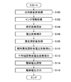
- FIG. 6 is a flowchart showing the procedure of the drive voltage adjusting method according to the first embodiment.
- FIG. 7 is a conceptual diagram of discharge characteristics for each module.
- FIG. 8 is a conceptual diagram of ejection characteristics of each head module in ink applied to printing.
- FIG. 1 is an overall configuration diagram of an inkjet printing apparatus according to the first embodiment.
- FIG. 2 is a perspective view showing a configuration example of the inkjet head.
- FIG. 3 is a functional block diagram of the inkjet printing apparatus shown in FIG.
- FIG. 9 is a functional block diagram of a print control unit applied to the inkjet printing apparatus according to the second embodiment.
- FIG. 10 is a table showing an example of a voltage coefficient applied to the drive voltage adjusting method according to the second embodiment.
- FIG. 11 is a conceptual diagram of relative concentration adjustment and average value adjustment.
- FIG. 12 is a flowchart showing the procedure of the drive voltage adjusting method according to the second embodiment.
- FIG. 13 is an explanatory diagram of the action and effect of the second embodiment.
- FIG. 1 is an overall configuration diagram of an inkjet printing apparatus according to the first embodiment.
- the inkjet printing device 10 is a printing device to which an inkjet method for printing an image on paper P by a single pass method is applied.
- FIG. 1 exemplifies a sheet of paper P.
- the paper P continuous paper may be applied.
- the material of the paper P paper, cloth, resin, metal and the like can be applied.
- the paper P either a penetrating medium or a non-penetrating medium may be applied.
- the inkjet printing device 10 includes a transport device 20, a jetting device 30, and an in-line sensor 40.
- the inkjet printing device 10 may include components (not shown in FIG. 1) such as a paper feeding device, an ink drying device, and an integrating device.
- the transport device 20 includes a jetting drum 22, a paper feed drum 24, a paper holding roller 26, and a paper discharge drum 28.
- the transport device 20 transports the paper P along a specified paper transport direction.
- the arrow line attached to the jetting drum 22 indicates the paper transport direction in the jetting drum 22.
- the arrow line attached to the paper feed drum 24 indicates the paper transport direction in the paper feed drum 24.
- the arrow line attached to the paper ejection drum 28 indicates the paper transport direction in the paper ejection drum 28.
- the paper transport direction described in the embodiment is an example of the medium transport direction.
- the jetting drum 22 is a drum having a cylindrical shape.
- the total length in the axial direction parallel to the rotation axis of the jetting drum 22 exceeds the total length in the paper width direction of the paper P having the maximum size.
- the above configuration is the same for the paper feed drum 24 and the paper discharge drum 28.
- the paper width direction is orthogonal to the paper transport direction.
- the paper width direction described in the embodiment is an example of the medium width direction.
- the term parallelism in the present specification may include substantially parallelism that can exert the same effect as the two directions in which the two intersecting directions are parallel.
- orthogonality may include a substantial orthogonality that may have the same effect as the two directions in which the two directions intersecting at an angle greater than 90 degrees or less than 90 degrees are orthogonal.
- the jetting drum 22 supports the paper P on the outer peripheral surface.
- a mode in which the paper P is supported on the outer peripheral surface of the jetting drum 22 a mode in which suction pressure is generated in a plurality of suction holes provided on the outer peripheral surface and suction pressure is applied to the paper P can be mentioned.
- the jetting drum 22 is provided with two grippers 23.
- the gripper 23 grips the tip of the paper P.
- the two grippers 23 are arranged at positions shifted by a distance corresponding to 180 degrees with respect to the rotation direction of the jetting drum 22.
- the gripper 23 includes a plurality of gripping claws and support members.
- the plurality of gripping claws are arranged along the rotation axis of the jetting drum 22.
- the plurality of gripping claws are supported so as to be openable and closable by using a support member.
- the illustration of the gripping claw and the support member is omitted.
- the jetting drum 22 is rotatably supported on a rotating shaft.
- a drive device including a motor, a drive mechanism, and the like is connected to the rotation shaft of the jetting drum 22.
- the jetting drum 22 rotates in a predetermined rotation direction according to the operation of the drive device. It should be noted that the illustration of a drive device including a motor, a drive mechanism, and the like is omitted.
- the jetting drum 22 supports the paper P on the outer peripheral surface and rotates around the rotation axis. As a result, the paper P is conveyed in the paper conveying direction along the outer peripheral surface of the jetting drum 22.
- the paper feed drum 24 includes one gripper 25.
- the gripper 25 may apply the same structure as the gripper 23.
- the paper feed drum 24 is connected to a drive device having the same configuration as the drive device provided in the jetting drum 22.
- the paper feed drum 24 rotates around a rotation axis.
- the paper P whose tip is gripped by the gripper 25 is conveyed in the paper conveying direction along the outer peripheral surface of the paper feed drum 24.
- the gripper 25 delivers the paper P to the gripper 23 at the medium delivery position.
- the paper holding roller 26 has a cylindrical shape.
- the total length of the paper holding roller 26 in the axial direction of the jetting drum 22 exceeds the total length in the paper width direction of the paper P having the maximum size.
- the paper holding roller 26 is rotatably supported on the rotating shaft.
- the paper holding roller 26 is connected to a pressing mechanism that presses the paper P toward the outer peripheral surface of the jetting drum 22.
- the paper holding roller 26 presses the paper P toward the outer peripheral surface of the jetting drum 22, and brings the paper P into close contact with the outer peripheral surface of the jetting drum 22.
- the paper ejection drum 28 includes one gripper 29.
- the gripper 29 may apply the same structure as the gripper 23.
- the gripper 29 delivers the paper P from the gripper 23 at the medium delivery position.
- the paper ejection drum 28 is connected to a drive device having the same configuration as the drive device provided in the jetting drum 22.
- the paper ejection drum 28 rotates around a rotation axis.
- the paper P whose tip is gripped by the gripper 29 is conveyed in the paper conveying direction along the outer peripheral surface of the output drum 28.
- the rotation axis of the jetting drum 22, the rotation axis of the paper feed drum 24, the rotation axis of the paper ejection drum 28, and the medium transfer position are not shown.
- the jetting device 30 includes an inkjet head 32C, an inkjet head 32M, an inkjet head 32Y, and an inkjet head 32K.
- the inkjet head 32C, the inkjet head 32M, the inkjet head 32Y, and the inkjet head 32K are arranged at positions facing the outer peripheral surface of the jetting drum 22.
- the inkjet head 32C, the inkjet head 32M, the inkjet head 32Y, and the inkjet head 32K are arranged at positions at equal intervals along the outer peripheral surface of the jetting drum 22.
- the inkjet head 32C, the inkjet head 32M, the inkjet head 32Y, and the inkjet head 32K may be collectively referred to as the inkjet head 32.
- the inkjet head 32C, the inkjet head 32M, the inkjet head 32Y, and the inkjet head 32K are print heads that eject water-based inks of cyan, magenta, yellow, and black, respectively.
- Aqueous ink refers to ink in which a coloring material such as a dye or a pigment is dissolved or dispersed in water or a solvent soluble in water.
- the inkjet head 32 may be applied with an ink other than the water-based ink, such as an ink containing an organic solvent.
- Ink is supplied to the inkjet head 32 from the ink tanks of the corresponding colors via the piping path.
- the illustration of the ink tank and the piping route is omitted.
- the inkjet head 32 is a line-type head capable of single-pass printing, in which the paper P supported on the outer peripheral surface of the jetting drum 22 is scanned once and printed.
- a serial type head may be applied to the inkjet head 32.
- a plurality of nozzles for ejecting ink are formed on the nozzle surface of the inkjet head 32. Multiple nozzles may apply a two-dimensional arrangement. For the two-dimensional arrangement of multiple nozzles, a matrix arrangement may be applied. Further, a water-repellent film is formed on the nozzle surface of the inkjet head 32.
- the inkjet head 32 can be configured by connecting a plurality of head modules in the paper width direction.
- the head module, nozzle, and water-repellent film are not shown.
- the nozzle surface is illustrated in FIG. 2 using reference numeral 33.
- Ink droplets are ejected from the inkjet head 32 toward the printing surface of the paper P. Droplets of ink ejected from the inkjet head 32 adhere to the paper P, and an image is printed on the printing surface of the paper P.
- an embodiment in which four color inks of cyan, magenta, yellow, and black are used is exemplified, but the ink color and the number of colors are not limited to the present embodiment.
- an embodiment using light color inks such as light magenta and light cyan, and an embodiment using special color inks such as green, orange, violet, white, clear and metallic may be applied.
- a plurality of inkjet heads 32 that eject ink of the same color may be arranged.
- the arrangement order of the inkjet heads 32 for each color is not limited to the mode shown in FIG.
- the jetting device 30 prints a test image such as a density measurement chart on the printed surface of the paper P.
- the in-line sensor 40 reads the test image printed on the print surface of the paper P and outputs the read data of the test image.
- the inkjet printing apparatus 10 analyzes the read data of the test image and performs various processes such as correction of the inkjet head 32 based on the analysis result.
- the in-line sensor 40 includes an image pickup device including a CCD image sensor.
- a CCD image sensor a line sensor in which a plurality of photoelectric conversion elements are arranged in a row may be applied.
- an area sensor in which a plurality of photoelectric conversion elements are arranged two-dimensionally may be applied.
- CCD is an abbreviation for Charge Coupled Device.
- the image pickup apparatus may apply an embodiment having an image pickup range corresponding to the full width of the image printed on the print surface of the paper P, or scan along the paper width direction and print on the print surface of the paper P. An embodiment of reading the full width of an image may be applied.
- FIG. 2 is a perspective view showing a configuration example of the inkjet head.
- the inkjet head 32 has a structure in which a plurality of head modules 34 are connected along the longitudinal direction.
- the plurality of head modules 34 are integrally supported by the support frame 36.
- the flexible substrate 38 is formed with electrical wiring for transmitting the drive voltage supplied to the discharge element provided in the head module 34.
- the discharge element includes a nozzle opening, a flow path communicating with the nozzle opening, and a pressure generating element.
- the pressure generating element applies a ejection pressure to the ink ejected from the nozzle opening.
- Piezoelectric elements may be applied as the pressure generating element.
- the head module 34 may apply a piezoelectric method of ejecting ink droplets from a nozzle opening according to the deflection deformation of the piezoelectric element.
- a heating element can be applied as the pressure generating element.
- the head module 34 may apply a thermal method of ejecting ink droplets from a nozzle opening by utilizing the phenomenon of ink film boiling.
- the discharge element, nozzle opening, flow path, and pressure generating element are not shown.
- the nozzle surface 33 of the head module 34 has a parallel quadrilateral shape. Dummy plates 39 are attached to both ends of the support frame 36. The nozzle surface 33 of the head module 34 has a rectangular shape as a whole when combined with the surface 39A of the dummy plate 39.
- FIG. 3 is a functional block diagram of the inkjet printing apparatus shown in FIG.
- the inkjet printing apparatus 10 includes one or more processors 100 and one or more memories 102. Further, the inkjet printing device 10 includes a communication interface 104.
- the communication interface 104 may be either a wired format or a wireless format.
- the inkjet printing device 10 acquires print data or the like from an external device such as a host computer 106 via the communication interface 104.
- the memory 102 includes a program memory 110, a parameter memory 112, and a data memory 114.
- the program memory 110 stores various programs including instructions that can be executed by using the processor 100.
- the parameter memory 112 stores various parameters necessary for executing the program.
- Various types of data are stored in the data memory 114.
- the data memory 114 may include a temporary storage area for various data.
- the memory 102 may be configured to include a computer-readable medium or the like which is a tangible object such as a semiconductor memory.
- the memory 102 may include a magnetic storage device such as a hard disk.
- the memory 102 may be configured by using a plurality of storage devices and the like.
- the plurality of storage devices and the like may include a plurality of different types of storage devices and the like.
- the storage device or the like constituting the memory 102 may be divided into a plurality of storage areas.
- the processor 100 executes a program stored in the program memory 110 to realize various functions of the inkjet printing device 10.
- the various processing units illustrated as the components of the processor 100 correspond to various functions of the inkjet printing apparatus 10.
- the system control unit 108 executes a program stored in the program memory 110, performs various processes of the inkjet printing device 10, and performs overall control of the inkjet printing device 10.
- the transport control unit 120 controls the operation of the transport device 20. That is, the transport control unit 120 controls the paper feed and the paper P transport speed. It should be noted that the term velocity in the present specification may include the meaning of velocity expressed using the absolute value of velocity.
- the print control unit 122 controls the ink ejection operation of the inkjet head 32 based on the print data.
- the print control unit 122 performs image processing for performing various conversion processing, various correction processing, halftone processing, and the like on the print data.
- the conversion process includes pixel number conversion, gradation conversion, color conversion, and the like.
- the correction process includes density unevenness correction, non-ejection correction for suppressing the visibility of image defects caused by the occurrence of non-ejection nozzles, and the like.
- the print control unit 122 ejects droplets of water-based ink of each color from the inkjet head 32 of each color toward the paper P at the timing when the paper P passes through the position facing the nozzle surface of the inkjet head 32.
- the read data processing unit 124 acquires read data such as a test image output from the inline sensor 40 and analyzes the acquired read data.
- the system control unit 108 corrects the inkjet head 32 based on the analysis result.
- the inkjet printing device 10 includes an input device 130.
- the processor 100 acquires an input signal output by the input device 130.
- the input device 130 may apply various operation members such as an operation panel, a keyboard, a mouse, a touch panel, and a trackball that receive input from the user.
- the input device 130 may be an appropriate combination thereof.
- the inkjet printing device 10 includes a display 132.
- the processor 100 transmits a display signal to the display 132.
- the display 132 displays information based on the acquired display signal. As the information to be displayed using the display 132, status information of the inkjet printing apparatus 10, setting information of various parameters, error information of the inkjet printing apparatus 10, and the like can be applied.
- the inkjet printing device 10 includes a touch panel type display, and the input device 130 and the display 132 can be integrated.
- FIG. 4 is a functional block diagram of the print control unit shown in FIG.
- the print control unit 122 includes a processor 200.
- the processor 200 may be configured as a part of the processor 100 shown in FIG. 3, or may be configured separately from the processor 100.
- the various processing units of the print control unit 122 illustrated as a component of the processor 200 correspond to various functions of the print control unit 122.
- the processor 200 executes a program stored in the program memory 110 and realizes various functions related to print control.
- the print control unit 122 includes a print data acquisition unit 202.
- the print data acquisition unit 202 acquires print data from the host computer 106 shown in FIG.
- the print data acquisition unit 202 stores the acquired print data in the data memory 114 or the like shown in FIG.
- the print control unit 122 includes a print data processing unit 204.
- the print data processing unit 204 performs various conversion processes, various correction processes, halftone processes, and the like on the print data to generate a halftone image for each ink color.
- the print control unit 122 includes a drive voltage generation unit 206.
- the drive voltage generation unit 206 generates a drive voltage to be supplied to the inkjet head 32 based on the halftone image.
- the drive voltage generation unit 206 acquires a drive waveform applied to the drive voltage via the drive waveform data acquisition unit 207.
- the acquisition includes a mode of reading the acquisition target data from the memory in which the acquisition target data is stored.
- the acquisition may include an aspect of generating the acquisition target data.
- the drive voltage generation unit 206 defines the correlation between the drive voltage and the discharge amount.
- the drive voltage in the correlation between the drive voltage and the discharge amount is the potential difference between the maximum potential and the reference potential. For example, when the drive waveform is triangular or trapezoidal, the height is the drive voltage.
- the correlation between the drive voltage and the discharge amount is stored in a table format or the like.
- the print control unit 122 includes a drive voltage adjustment unit 208.
- the drive voltage adjusting unit 208 adjusts the drive voltage supplied to the inkjet head 32 for each head module 34 shown in FIG.
- the print control unit 122 sets the correlation between the drive voltage and the discharge amount for each head module 34.
- a common drive voltage for each head module 34 is supplied to the plurality of pressure generating elements provided in the head module 34.
- the print control unit 122 includes a drive voltage output unit 210.
- An electric circuit that amplifies the drive voltage is applied to the drive voltage output unit 210.
- the drive voltage output from the drive voltage output unit 210 is supplied to the inkjet head 32.
- the inkjet head 32 ejects ink droplets from the nozzle opening toward the paper P according to the drive voltage output from the drive voltage output unit 210. A color image is printed on the paper P.
- the print control unit 122 includes an ink information acquisition unit 214.
- the ink information acquisition unit 214 acquires ink identification information that identifies the ink applied to printing.
- the ink information acquisition unit 214 acquires ink characteristic information representing the characteristics of the ink corresponding to the ink identification information.
- the product name, model, etc. indicating the type of ink are applied to the ink identification information.
- An example of ink characteristic information is the rate of change of the voltage coefficient derived from the measurement result of the ejection amount measurement in the shipping inspection.
- Another example of ink property information is the ratio of the viscosity of the ink applied for printing to the viscosity of the ink applied for shipping inspection.
- the ejection amount is the volume of ink droplets ejected in a unit period.
- the voltage coefficient is applied to correct the correlation between the drive voltage and the discharge amount.
- the drive voltage corresponding to the target discharge amount is defined based on the correlation between the drive voltage and the discharge amount.
- the target discharge amount means a design discharge amount corresponding to an arbitrary drive voltage.
- the print control unit 122 includes a shipping inspection value acquisition unit 216.
- the shipping inspection includes an inspection of the ejection characteristics of each head module 34 in the inkjet head 32.
- the shipping inspection value is derived for the specified inspection item.
- the shipping inspection value is stored in the memory 102 shown in FIG.
- An example of the shipping inspection value is the voltage coefficient of the ink applied to the shipping inspection.
- the reference is 100%, a value exceeding 100% represents an increase in the drive voltage, and a value less than 100% represents a decrease in the drive voltage.
- the voltage coefficient can be derived based on the result of discharge amount measurement.
- the voltage coefficient can be derived based on the electrical characteristics such as the capacitance of the piezoelectric element and the mechanical characteristics such as the displacement amount of the piezoelectric element.
- the voltage coefficient is increased according to the increase in the electrical characteristic value of the piezoelectric element and the mechanical characteristic value of the piezoelectric element.
- the voltage coefficient is reduced according to the decrease in the electrical characteristic value of the piezoelectric element and the mechanical characteristic value of the piezoelectric element.
- the voltage coefficient can be derived based on the measured value of the density of the printed image and the measured value of the components of the printed image. Examples of the measured values of the components of the printed image include the width of the lines constituting the printed image and the diameters of the dots constituting the printed image.
- the discharge amount can be derived based on the measured value in the printed image, and the voltage coefficient can be derived based on the derived discharge amount.
- the voltage coefficient of the shipping inspection value described in the embodiment is an example of module characteristics and an example of an initial voltage coefficient.
- the print control unit 122 includes a correction coefficient setting unit 218.
- the correction coefficient setting unit 218 derives the voltage correction amount derived at the time of shipping inspection and the correction coefficient which is the rate at which the voltage correction value fluctuates when the ink applied to printing is used.
- the correction coefficient setting unit 218 sets a correction coefficient applied to the correction of the voltage coefficient due to the difference in ink.
- the correction coefficient the ratio of the voltage coefficient derived by using the ejection amount measurement value of the ink applied to printing to the voltage coefficient obtained as the shipping inspection value can be applied.
- the ejection amount measurement value of the ink applied to printing can be obtained in advance of printing in a device other than the inkjet printing device 10 such as an inspection device.
- the correction factor can be derived based on the viscosity of the ink applied to printing.
- the correction coefficient derived based on the viscosity of the ink may be less accurate than the correction coefficient derived based on the result of ejection amount measurement, but when the correction coefficient cannot be obtained in advance of printing. It is valid.
- the drive voltage adjusting unit 208 applies a correction coefficient in the ink applied to printing to the voltage coefficient acquired as a shipping inspection value, and corrects the voltage coefficient for each head module 34.
- the correction coefficient may be the ratio of the voltage coefficient of the ink applied to printing to the voltage coefficient of the shipping inspection value.
- the difference between the voltage coefficient of the ink applied to printing and the voltage coefficient of the shipping inspection value may be applied.
- the drive voltage adjusting unit 208 adjusts the drive voltage by applying a voltage coefficient corrected according to the ink applied to printing.
- the drive voltage output unit 210 outputs a drive voltage adjusted according to the ink applied to printing.
- the print control unit 122 shown in the embodiment is an example of a drive voltage supply device.
- FIG. 5 is a table showing an example of the voltage coefficient applied to the drive voltage adjusting method according to the first embodiment.
- the voltage coefficient shown in FIG. 5 is expressed by applying a percentage based on 100.
- the voltage coefficient a is a shipping inspection value.
- the correction coefficient b represents the difference between the voltage coefficient applied to printing and the voltage coefficient of the shipping inspection value.
- the correction coefficient b may be the ratio of the voltage coefficient applied to printing to the voltage coefficient of the shipping inspection value.
- the voltage coefficient in the ink applied to printing is expressed as a * b. * Represents a difference or ratio.
- the head module 34 described as Module # 1 is designed to be driven by a drive voltage corresponding to a target ejection amount when a voltage coefficient corrected based on the ink characteristics applied to printing is applied. Adjusted to 104 percent of the voltage.
- the voltage coefficient of the ink applied to the printing described in the embodiment is an example of the first voltage coefficient.
- processors can be applied to the hardware of the processing unit that performs the various processes shown in FIGS. 3 and 4.
- the processing unit may be called a processing unit.
- Various processors include a CPU (Central Processing Unit), a PLD (Programmable Logic Device), an ASIC (Application Specific Integrated Circuit), and the like.
- the CPU is a general-purpose processor that executes programs and functions as various processing units.
- the PLD is a processor whose circuit configuration can be changed after manufacturing.
- An example of PLD is FPGA (Field Programmable Gate Array).
- An ASIC is a dedicated electrical circuit having a circuit configuration specifically designed to perform a particular process.
- One processing unit may be composed of one of these various processors, or may be composed of two or more processors of the same type or different types.
- one processing unit may be configured by using a plurality of FPGAs and the like.
- One processing unit may be configured by combining one or more FPGAs and one or more CPUs.
- a plurality of processing units may be configured by using one processor.
- one processor is configured by combining one or more CPUs and software, and one processor functions as a plurality of processing units.
- Such a form is represented by a computer such as a client terminal device and a server device.
- An example is a mode in which a processor that realizes the functions of the entire system including a plurality of processing units by using one IC chip is used.
- a processor that realizes the functions of the entire system including a plurality of processing units by using one IC chip is used.
- Such a form is typified by a system-on-chip (SystemOnChip) and the like.
- IC is an abbreviation for Integrated Circuit.
- the system-on-chip may be described as SoC by using the abbreviation of System On Chip.
- the various processing units are configured by using one or more of the above-mentioned various processors as a hardware-like structure.
- the hardware-like structure of various processors is, more specifically, an electric circuit (circuitry) in which circuit elements such as semiconductor elements are combined.
- FIG. 6 is a flowchart showing the procedure of the drive voltage adjusting method according to the first embodiment.
- the shipping inspection value acquisition unit 216 shown in FIG. 3 acquires the shipping inspection value for each head module 34.
- the shipping inspection value may be acquired from an external device or the like via the communication interface 104 shown in FIG. 2, or the shipping inspection value stored inside the inkjet printing device 10 may be read out.
- the process proceeds to the ink information acquisition step S12.
- the ink information acquisition unit 214 acquires ink characteristic information representing the ink characteristics of the ink applied to printing. After the ink information acquisition step S12, the process proceeds to the correction coefficient setting step S14.
- the correction coefficient setting unit 218 sets the correction coefficient according to the ink applied to printing.
- the correction coefficient setting step S14 may include a correction coefficient acquisition step of acquiring the correction coefficient.
- the correction coefficient setting step S14 may include a correction coefficient derivation step for deriving the correction coefficient. After the correction coefficient setting step S14, the process proceeds to the voltage coefficient correction step S16.
- the drive voltage adjusting unit 208 applies a correction coefficient corresponding to the ink applied to printing to correct the voltage coefficient of the shipping inspection value, and the voltage corresponding to the ink applied to printing. Derive the coefficient. After the voltage coefficient correction step S16, the process proceeds to the drive voltage adjustment step S18.
- the drive voltage adjusting unit 208 applies a voltage coefficient corresponding to the ink applied to printing for each head module 34, and adjusts the drive voltage for each head module 34. After the drive voltage adjustment step S18, the process proceeds to the drive voltage output step S20.
- the drive voltage output unit 210 outputs the drive voltage adjusted for each head module 34 in the drive voltage adjustment process S18.
- FIG. 7 is a conceptual diagram of discharge characteristics for each module.
- the figure illustrates the difference in the discharge amount when the drive voltage before adjustment using the voltage coefficient is supplied to the plurality of head modules 34 using the graph format.
- the horizontal axis represents the position of the head module 34.
- the vertical axis represents the discharge amount.
- the discharge amount is measured for each head module 34, and the voltage coefficient is derived for each head module 34 based on the result of the discharge amount measurement.
- the target discharge amount is achieved when the drive voltage adjusted using the voltage coefficient of the shipping inspection value is applied.
- FIG. 8 is a conceptual diagram of ejection characteristics of each head module in ink applied to printing.
- FIG. 8 illustrates an example of ejection characteristics for each module when the ink applied for printing is different from the ink applied for ejection amount measurement in shipping inspection.
- the actual ejection amount for each head module 34 is the target due to the difference in ink characteristics such as the viscosity of the ink. It is different from the discharge amount. Therefore, the voltage coefficient is corrected for each head module 34 based on the ink characteristics of the ink applied to printing, and the drive voltage is adjusted using the corrected voltage coefficient. As a result, the target discharge amount is realized for all the head modules 34.
- the inkjet printing apparatus 10 and the drive voltage adjusting method according to the first embodiment can obtain the following effects.
- [1] Corrects the voltage factor obtained as a shipping inspection value based on the ink characteristics applied to printing.
- the drive voltage adjusted by using the corrected voltage coefficient is supplied to the inkjet head 32.
- variations in the ejection amount of the head module 34 due to the ejection characteristics of each head module 34 can be suppressed, and density unevenness in the printed image can be suppressed.
- the voltage coefficient is derived based on the electrical characteristics of the piezoelectric element and the mechanical characteristics of the piezoelectric element. As a result, even when it is difficult to measure the ejection amount, it is possible to correct the voltage coefficient based on the ink characteristics.
- the voltage coefficient is derived based on the measured values of the components of the printed image. As a result, even when it is difficult to measure the ejection amount, it is possible to correct the voltage coefficient based on the ink characteristics.
- the ratio of the viscosity of the ink applied to printing to the viscosity of the ink applied to the shipping inspection is applied. This makes it possible to correct the voltage coefficient based on the viscosity of the ink.
- the rate of change of the voltage coefficient derived from the measurement result of the ejection amount measurement in the shipping inspection is applied.
- the voltage coefficient can be corrected based on the result of the discharge amount measurement.
- FIG. 9 is a functional block diagram of a print control unit applied to the inkjet printing apparatus according to the second embodiment.
- the inkjet printing apparatus according to the second embodiment measures the density of a printed image using a drive voltage adjusted based on a voltage coefficient corresponding to the ink applied to printing, and based on the density measurement value of the printed image.
- the voltage coefficient for each head module 34 is corrected.
- a density measurement data processing unit 220 is added to the processor 200 shown in FIG.
- the density measurement data processing unit 220 acquires the read data of the printed image for each head module 34 from the inline sensor 40.
- the density measurement data processing unit 220 derives the density measurement value of the printed image for each head module 34 based on the read data of the printed image.
- the correction coefficient setting unit 218 derives a voltage coefficient that realizes a specified target concentration value for each head module 34.
- the target concentration value the average value of the concentration measurements in two or more head modules 34 may be applied.
- the concentration measurement value in any one head module 34 may be applied.
- the density measurement data processing unit 220 may derive the correlation between the voltage coefficient and the density value based on the read data of a plurality of density measurement charts printed by changing the voltage coefficient.
- the correction coefficient setting unit 218 can derive the voltage coefficient corresponding to the target concentration value by using the correlation between the voltage coefficient and the concentration value.
- the voltage coefficient adjusted for relative density is derived, and the voltage coefficient adjusted for relative density is applied to adjust the drive voltage.
- FIG. 10 is a table showing an example of the voltage coefficient applied to the drive voltage adjusting method according to the second embodiment.
- the value in the voltage coefficient column of the shipping inspection value and the value in the voltage coefficient column for assigning the correction coefficient are the same as those in the table shown in FIG.
- these explanations will be omitted.
- the correction coefficient setting unit 218 shown in FIG. 9 derives and sets the voltage coefficient c after the relative concentration adjustment shown in FIG. As the voltage coefficient c shown in the figure, the correlation between the voltage coefficient and the concentration value derived by irregularly increasing or decreasing the voltage coefficient is applied to each head module 34.
- the correction coefficient setting unit 218 calculates the ratio of the average value of the voltage coefficient before the relative concentration adjustment and the average value of the voltage coefficient after the relative concentration adjustment to the voltage coefficient c after the relative concentration adjustment for each head module 34. Multiply the coefficient c to derive the voltage coefficient after adjusting the average value.
- the voltage coefficient after adjusting the average value is expressed as c ⁇ ⁇ Avg (a * b) / Avg (c) ⁇ .
- Avg represents the average value of the values in parentheses in the plurality of head modules 34.
- the numerical value in the Average column shown in FIG. 10 represents the average value of the voltage coefficients in the plurality of head modules 34.
- the voltage coefficient after adjusting the average value is derived, in which the ratio between the voltage coefficient a in the shipping inspection value and the voltage coefficient in the inkjet printing apparatus 10 applied to printing is maintained.
- FIG. 11 is a conceptual diagram of relative concentration adjustment and average value adjustment.
- the concentration measurement value for each head module 34 is schematically illustrated using a graph format.
- the horizontal axis of the graph shown in the figure represents the position of the head module 34.
- the vertical axis represents the measured concentration value.
- the concentration measurement value for each head module 34 is different from the target concentration value.
- the density measurement value of the printed image for each head module 34 is adjusted to the target relative density value.
- the broken line arrow line attached to each head module 34 schematically represents the relative density adjustment.
- the density measurement value of the printed image for each head module 34 is adjusted to the target absolute density value.
- the solid arrow line attached to each head module 34 schematically represents the relative density adjustment.
- FIG. 12 is a flowchart showing the procedure of the drive voltage adjusting method according to the second embodiment.
- the shipping inspection value acquisition process S100, the ink information acquisition process S102, the correction coefficient setting process S104, and the voltage coefficient correction step S106 shown in FIG. 6 are from the shipping inspection value acquisition process S10 to the voltage coefficient correction step S16 shown in FIG. It is the same as each process. Here, these explanations will be omitted.
- the process proceeds to the concentration measurement value acquisition step S108.
- the concentration measurement data processing unit 220 shown in FIG. 9 acquires the concentration measurement value for each head module 34 to which the drive voltage to which the voltage coefficient before the relative concentration adjustment is applied is applied. After the concentration measurement value acquisition step S108, the process proceeds to the voltage coefficient derivation step S110 after adjusting the relative concentration.
- the correction coefficient setting unit 218 derives and sets the relative concentration adjusted voltage coefficient c based on the concentration measurement value acquired in the concentration measurement value acquisition step S108. After the relative concentration adjusted voltage coefficient derivation step S110, the process proceeds to the average value adjusted voltage coefficient derivation step S112.
- the correction coefficient setting unit 218 derives and sets the average value adjusted voltage coefficient shown in FIG. After the voltage coefficient derivation step S112 after adjusting the average value, the process proceeds to the drive voltage adjustment step S114 and the drive voltage output step S116.
- the drive voltage adjustment process S114 and the drive voltage output process S116 are the same as the drive voltage adjustment process S18 and the drive voltage output process S20 shown in FIG. 6, respectively. Here, these explanations will be omitted.
- the voltage coefficient after adjusting the relative concentration described in the embodiment is an example of the second voltage coefficient.
- the voltage coefficient after adjusting the average value described in the embodiment is an example of the third voltage coefficient.
- a voltage coefficient based on the density measurement value is derived in advance for each lot of the paper P.
- the lot information of the paper P can be acquired, the drive voltage can be adjusted by using the voltage coefficient for each lot, and the density unevenness of the printed image due to the variation between the lots of the paper P can be suppressed.
- the drive voltage adjusting method according to the second embodiment can obtain the following effects.
- the voltage coefficient c after the relative concentration adjustment is derived, and the drive voltage is adjusted using the voltage coefficient c after the relative concentration adjustment.
- the print density among the head modules 34 is made uniform.
- the print density represents the density in the printed image printed by using the head module 34.
- FIG. 13 is an explanatory diagram of the action and effect of the second embodiment.
- the three head modules 34 shown in the figure may be, for example, the head modules 34 described as Module # 1, Module # 2 and Module # 3 in the table shown in FIG.
- Each of the print image 300, the print image 302, and the print image 304 is printed by supplying a drive voltage adjusted by applying the voltage coefficient of the shipping inspection value to each head module 34.
- the print image 306 including the print image 300, the print image 302, and the print image 304 density unevenness due to the ink characteristics occurs.
- the print image 316 including the print image 310, the print image 312, and the print image 3144 the voltage coefficient after the relative density adjustment is applied, and the adjusted drive voltage is supplied to each head module 34 and printed.
- the voltage coefficient after adjusting the average value is derived from the voltage coefficient after adjusting the relative concentration, and the drive voltage is adjusted using the voltage coefficient after adjusting the average value.
- the print density of each head module 34 is set as the target absolute density.
- a drive voltage adjusted by applying the voltage coefficient after adjusting the average value is supplied to each head module 34 and printed.
- the print image 326 including the print image 320, the print image 322, and the print image 324 realizes an absolute target density.
- the inkjet printing apparatus 10 shown in FIG. 1 may apply an embodiment using a pretreatment liquid.
- the pretreatment liquid include a precoat liquid that aggregates or insolubilizes the coloring material contained in the ink.
- the inkjet printing apparatus 10 may include a precoat coating device for applying a precoat liquid and a precoat liquid drying device for drying the paper P coated with the precoat liquid.
- the printed image may have uneven density due to variations in the application of the precoat liquid.
- the drive voltage is adjusted using the voltage coefficient after adjusting the relative concentration. As a result, the print density of each head module 34 is made uniform.
- the inkjet printing apparatus 10 shown in FIG. 1 may apply continuous paper as paper P.
- a roll-to-roll format can be applied as the transport mode of the paper P.
- the load when using the paper P for inkjet printing is large, and the occurrence of density unevenness in the printed image becomes remarkable.
- the adjustment of the drive voltage to which the voltage coefficient based on the density measurement value of the paper P according to the paper information is applied can suppress the density unevenness of the printed image.
- the print control unit 122 shown in FIGS. 3 and 4 may be combined with the inkjet head 32 shown in FIGS. 1 and 2 to form a head device which is an external device of the inkjet printing device 10.
- a program corresponding to the inkjet printing apparatus 10 and the drive voltage adjusting method can be configured. That is, it is possible to configure a program for realizing the functions of various processing units shown in FIGS. 3 and 4 and each process shown in FIGS. 6 and 11 on a computer.
- printing device is synonymous with terms such as a printing machine, a printer, a printing device, an image recording device, an image forming device, an image output device, and a drawing device.
- the image shall be interpreted in a broad sense, and includes a color image, a black-and-white image, a single-color image, a gradation image, a uniform density image, and the like.
- printing includes the concepts of terms such as image recording, image formation, printing, drawing and printing.
- device can include the concept of a system.
- the image is not limited to a photographic image, but is used as a comprehensive term including patterns, characters, symbols, line drawings, mosaic patterns, color-coded patterns and various other patterns, and appropriate combinations thereof. Further, the term image may include the meaning of an image signal and image data representing an image.
- Inkjet printing device 20 Conveyor device 22 Jetting drum 23 Gripper 24 Feeding drum 25 Gripper 26 Paper holding roller 28 Paper ejection drum 29 Gripper 30 Jetting device 32 Jetting device 32 Inkjet head 32C Inkjet head 32M Inkjet head 32Y Inkjet head 32K Inkjet head 33 Nozzle Surface 34 Head module 36 Support frame 38 Flexible board 39 Dummy plate 39A Surface 40 Inline sensor 100 Processor 102 Memory 104 Communication interface 106 Host computer 108 System control unit 110 Program memory 112 Parameter memory 114 Data memory 120 Transport control unit 122 Print control unit 122A Print control unit 124 Read data processing unit 130 Input device 132 Display 200 Processor 200A Processor 202 Print data acquisition unit 204 Print data processing unit 206 Drive voltage generation unit 207 Drive waveform data acquisition unit 208 Drive voltage adjustment unit 210 Drive voltage output unit 214 Ink Information acquisition unit 216 Shipment inspection value acquisition unit 218 Correction coefficient setting unit 220 Density measurement data processing unit 300 Print image 302 Print image 304 Print image 306 Print image
Landscapes
- Engineering & Computer Science (AREA)
- Quality & Reliability (AREA)
- Ink Jet (AREA)
- Particle Formation And Scattering Control In Inkjet Printers (AREA)
Priority Applications (3)
| Application Number | Priority Date | Filing Date | Title |
|---|---|---|---|
| JP2022530494A JP7350177B2 (ja) | 2020-06-12 | 2021-06-02 | ヘッド装置、インクジェット印刷装置及び駆動電圧調整方法 |
| EP21820945.0A EP4166335B1 (en) | 2020-06-12 | 2021-06-02 | Head device, inkjet printing apparatus, and method for regulating drive voltage |
| US18/059,568 US12187032B2 (en) | 2020-06-12 | 2022-11-29 | Head device, ink jet printing device, and driving voltage adjustment method |
Applications Claiming Priority (2)
| Application Number | Priority Date | Filing Date | Title |
|---|---|---|---|
| JP2020-102125 | 2020-06-12 | ||
| JP2020102125 | 2020-06-12 |
Related Child Applications (1)
| Application Number | Title | Priority Date | Filing Date |
|---|---|---|---|
| US18/059,568 Continuation US12187032B2 (en) | 2020-06-12 | 2022-11-29 | Head device, ink jet printing device, and driving voltage adjustment method |
Publications (1)
| Publication Number | Publication Date |
|---|---|
| WO2021251223A1 true WO2021251223A1 (ja) | 2021-12-16 |
Family
ID=78846046
Family Applications (1)
| Application Number | Title | Priority Date | Filing Date |
|---|---|---|---|
| PCT/JP2021/020926 Ceased WO2021251223A1 (ja) | 2020-06-12 | 2021-06-02 | ヘッド装置、インクジェット印刷装置及び駆動電圧調整方法 |
Country Status (4)
| Country | Link |
|---|---|
| US (1) | US12187032B2 (https=) |
| EP (1) | EP4166335B1 (https=) |
| JP (1) | JP7350177B2 (https=) |
| WO (1) | WO2021251223A1 (https=) |
Citations (12)
| Publication number | Priority date | Publication date | Assignee | Title |
|---|---|---|---|---|
| JPH0261645B2 (https=) | 1983-09-16 | 1990-12-20 | Rexnord Inc | |
| JPH04250054A (ja) * | 1991-01-18 | 1992-09-04 | Canon Inc | インクジェット記録装置 |
| JP2003182056A (ja) * | 2001-12-18 | 2003-07-03 | Sii Printek Inc | インクジェット式記録装置 |
| JP2006198902A (ja) | 2005-01-20 | 2006-08-03 | Fuji Xerox Co Ltd | 印字装置及び印字方法 |
| US20070195120A1 (en) * | 2006-02-22 | 2007-08-23 | Kim Jong-Beom | Method of controlling ink ejecting characteristics of inkjet head |
| JP2008093853A (ja) * | 2006-10-06 | 2008-04-24 | Canon Inc | インクジェット記録装置およびインクジェット記録方法 |
| JP2009196276A (ja) * | 2008-02-22 | 2009-09-03 | Riso Kagaku Corp | 印刷装置および印刷処理方法 |
| JP2012076376A (ja) * | 2010-10-01 | 2012-04-19 | Fujifilm Corp | インクジェット記録装置及び方法 |
| JP6042295B2 (ja) | 2013-09-04 | 2016-12-14 | 富士フイルム株式会社 | 記録ヘッド及びその製造方法並びに記録装置 |
| WO2017047448A1 (ja) * | 2015-09-17 | 2017-03-23 | コニカミノルタ株式会社 | インクジェット記録装置及びインクジェット記録装置のインク吐出調整方法 |
| JP2019205974A (ja) | 2018-05-29 | 2019-12-05 | キヤノン株式会社 | インクジェット装置、およびそれを用いた機能素子の製造方法 |
| JP2019217649A (ja) | 2018-06-18 | 2019-12-26 | セイコーエプソン株式会社 | 液体吐出装置および駆動回路 |
Family Cites Families (4)
| Publication number | Priority date | Publication date | Assignee | Title |
|---|---|---|---|---|
| JP2007210234A (ja) * | 2006-02-10 | 2007-08-23 | Seiko Epson Corp | 適正駆動電圧決定装置、及び、適正駆動電圧決定方法 |
| JP5293245B2 (ja) * | 2009-02-10 | 2013-09-18 | セイコーエプソン株式会社 | 流体噴射装置のヘッドの駆動パルス設定方法 |
| JP5760918B2 (ja) * | 2011-09-30 | 2015-08-12 | ブラザー工業株式会社 | 液体吐出装置 |
| JP6561645B2 (ja) | 2015-07-10 | 2019-08-21 | 株式会社リコー | 液滴吐出装置、画像形成装置、液滴吐出装置の制御方法、及びプログラム |
-
2021
- 2021-06-02 EP EP21820945.0A patent/EP4166335B1/en active Active
- 2021-06-02 WO PCT/JP2021/020926 patent/WO2021251223A1/ja not_active Ceased
- 2021-06-02 JP JP2022530494A patent/JP7350177B2/ja active Active
-
2022
- 2022-11-29 US US18/059,568 patent/US12187032B2/en active Active
Patent Citations (12)
| Publication number | Priority date | Publication date | Assignee | Title |
|---|---|---|---|---|
| JPH0261645B2 (https=) | 1983-09-16 | 1990-12-20 | Rexnord Inc | |
| JPH04250054A (ja) * | 1991-01-18 | 1992-09-04 | Canon Inc | インクジェット記録装置 |
| JP2003182056A (ja) * | 2001-12-18 | 2003-07-03 | Sii Printek Inc | インクジェット式記録装置 |
| JP2006198902A (ja) | 2005-01-20 | 2006-08-03 | Fuji Xerox Co Ltd | 印字装置及び印字方法 |
| US20070195120A1 (en) * | 2006-02-22 | 2007-08-23 | Kim Jong-Beom | Method of controlling ink ejecting characteristics of inkjet head |
| JP2008093853A (ja) * | 2006-10-06 | 2008-04-24 | Canon Inc | インクジェット記録装置およびインクジェット記録方法 |
| JP2009196276A (ja) * | 2008-02-22 | 2009-09-03 | Riso Kagaku Corp | 印刷装置および印刷処理方法 |
| JP2012076376A (ja) * | 2010-10-01 | 2012-04-19 | Fujifilm Corp | インクジェット記録装置及び方法 |
| JP6042295B2 (ja) | 2013-09-04 | 2016-12-14 | 富士フイルム株式会社 | 記録ヘッド及びその製造方法並びに記録装置 |
| WO2017047448A1 (ja) * | 2015-09-17 | 2017-03-23 | コニカミノルタ株式会社 | インクジェット記録装置及びインクジェット記録装置のインク吐出調整方法 |
| JP2019205974A (ja) | 2018-05-29 | 2019-12-05 | キヤノン株式会社 | インクジェット装置、およびそれを用いた機能素子の製造方法 |
| JP2019217649A (ja) | 2018-06-18 | 2019-12-26 | セイコーエプソン株式会社 | 液体吐出装置および駆動回路 |
Non-Patent Citations (1)
| Title |
|---|
| See also references of EP4166335A4 |
Also Published As
| Publication number | Publication date |
|---|---|
| US20230097719A1 (en) | 2023-03-30 |
| JPWO2021251223A1 (https=) | 2021-12-16 |
| JP7350177B2 (ja) | 2023-09-25 |
| US12187032B2 (en) | 2025-01-07 |
| EP4166335A4 (en) | 2023-11-08 |
| EP4166335A1 (en) | 2023-04-19 |
| EP4166335B1 (en) | 2025-01-22 |
Similar Documents
| Publication | Publication Date | Title |
|---|---|---|
| US8733877B2 (en) | Method and apparatus for detecting discharge defect, image processing apparatus, computer-readable recording medium, and printing system | |
| US7918521B2 (en) | Droplet ejecting apparatus | |
| JP5293245B2 (ja) | 流体噴射装置のヘッドの駆動パルス設定方法 | |
| JP6005616B2 (ja) | インクジェットヘッドの補正方法及びインクジェット記録装置 | |
| US11312128B2 (en) | Head driving device, liquid discharge apparatus, and head driving method | |
| JP2011173324A (ja) | 画像記録装置及び画像記録装置のヘッド調整方法 | |
| WO2014112313A1 (ja) | ヘッド調整方法、ヘッド駆動装置および画像形成装置 | |
| US7645010B2 (en) | Ink ejection amount measurement method and ink ejection amount measurement system | |
| JP6761545B2 (ja) | 画像形成装置及びその制御方法 | |
| JP2012250472A (ja) | インクジェット記録ヘッドの状態監視装置及びインクジェット記録装置 | |
| JP5894046B2 (ja) | 画像処理方法、画像処理装置、画像処理プログラム及び画像記録装置 | |
| JP7350177B2 (ja) | ヘッド装置、インクジェット印刷装置及び駆動電圧調整方法 | |
| JP2011218560A (ja) | 濃度補正方法、及び、印刷装置 | |
| JP5447160B2 (ja) | 流体噴射装置の調整方法及び流体噴射装置の製造方法 | |
| US12485686B2 (en) | Inkjet printing device and printing method for printing an image on a continuous medium | |
| JP7796541B2 (ja) | 吐出制御装置、インクジェット印刷システム、印刷条件決定方法及びプログラム | |
| JPWO2015182345A1 (ja) | 画像記録装置、画像記録方法、画像記録プログラム、補正情報生成装置、補正情報生成方法、及び補正情報生成プログラム | |
| JP7732852B2 (ja) | 記録ヘッドの制御装置及び制御方法、印刷装置 | |
| JP2011245666A (ja) | 流体噴射装置の調整方法及び流体噴射装置の製造方法 | |
| JP5213615B2 (ja) | 画像形成装置および画像形成方法 | |
| JP6878157B2 (ja) | 液滴吐出ヘッドの製造方法、画像形成装置の製造方法、液滴吐出ヘッド及び画像形成装置 | |
| JP2010194754A (ja) | 流体噴射装置の製造方法 | |
| JP2015217525A (ja) | 液滴吐出条件の設定方法、液滴吐出方法、および液滴吐出装置 | |
| JP2010201639A (ja) | 流体噴射装置の製造方法 | |
| JP2010082815A (ja) | 画像形成方法、画像形成装置および画像形成システム |
Legal Events
| Date | Code | Title | Description |
|---|---|---|---|
| 121 | Ep: the epo has been informed by wipo that ep was designated in this application |
Ref document number: 21820945 Country of ref document: EP Kind code of ref document: A1 |
|
| ENP | Entry into the national phase |
Ref document number: 2022530494 Country of ref document: JP Kind code of ref document: A |
|
| ENP | Entry into the national phase |
Ref document number: 2021820945 Country of ref document: EP Effective date: 20230112 |
|
| NENP | Non-entry into the national phase |
Ref country code: DE |