EP4163520B1 - Protective structure for drive device - Google Patents
Protective structure for drive device Download PDFInfo
- Publication number
- EP4163520B1 EP4163520B1 EP20940114.0A EP20940114A EP4163520B1 EP 4163520 B1 EP4163520 B1 EP 4163520B1 EP 20940114 A EP20940114 A EP 20940114A EP 4163520 B1 EP4163520 B1 EP 4163520B1
- Authority
- EP
- European Patent Office
- Prior art keywords
- flange
- gearbox
- electric power
- power generator
- drive device
- Prior art date
- Legal status (The legal status is an assumption and is not a legal conclusion. Google has not performed a legal analysis and makes no representation as to the accuracy of the status listed.)
- Active
Links
Images


Classifications
-
- F—MECHANICAL ENGINEERING; LIGHTING; HEATING; WEAPONS; BLASTING
- F16—ENGINEERING ELEMENTS AND UNITS; GENERAL MEASURES FOR PRODUCING AND MAINTAINING EFFECTIVE FUNCTIONING OF MACHINES OR INSTALLATIONS; THERMAL INSULATION IN GENERAL
- F16H—GEARING
- F16H57/00—General details of gearing
- F16H57/02—Gearboxes; Mounting gearing therein
- F16H57/031—Gearboxes; Mounting gearing therein characterised by covers or lids for gearboxes
-
- B—PERFORMING OPERATIONS; TRANSPORTING
- B62—LAND VEHICLES FOR TRAVELLING OTHERWISE THAN ON RAILS
- B62D—MOTOR VEHICLES; TRAILERS
- B62D25/00—Superstructure or monocoque structure sub-units; Parts or details thereof not otherwise provided for
- B62D25/20—Floors or bottom sub-units
- B62D25/2072—Floor protection, e.g. from corrosion or scratching
-
- B—PERFORMING OPERATIONS; TRANSPORTING
- B62—LAND VEHICLES FOR TRAVELLING OTHERWISE THAN ON RAILS
- B62D—MOTOR VEHICLES; TRAILERS
- B62D25/00—Superstructure or monocoque structure sub-units; Parts or details thereof not otherwise provided for
- B62D25/20—Floors or bottom sub-units
-
- B—PERFORMING OPERATIONS; TRANSPORTING
- B60—VEHICLES IN GENERAL
- B60R—VEHICLES, VEHICLE FITTINGS, OR VEHICLE PARTS, NOT OTHERWISE PROVIDED FOR
- B60R13/00—Elements for body-finishing, identifying, or decorating; Arrangements or adaptations for advertising purposes
- B60R13/08—Insulating elements, e.g. for sound insulation
- B60R13/0861—Insulating elements, e.g. for sound insulation for covering undersurfaces of vehicles, e.g. wheel houses
-
- B—PERFORMING OPERATIONS; TRANSPORTING
- B62—LAND VEHICLES FOR TRAVELLING OTHERWISE THAN ON RAILS
- B62D—MOTOR VEHICLES; TRAILERS
- B62D21/00—Understructures, i.e. chassis frame on which a vehicle body may be mounted
- B62D21/15—Understructures, i.e. chassis frame on which a vehicle body may be mounted having impact absorbing means, e.g. a frame designed to permanently or temporarily change shape or dimension upon impact with another body
- B62D21/152—Front or rear frames
- B62D21/155—Sub-frames or underguards
-
- B—PERFORMING OPERATIONS; TRANSPORTING
- B62—LAND VEHICLES FOR TRAVELLING OTHERWISE THAN ON RAILS
- B62D—MOTOR VEHICLES; TRAILERS
- B62D35/00—Vehicle bodies characterised by streamlining
- B62D35/02—Streamlining the undersurfaces
-
- F—MECHANICAL ENGINEERING; LIGHTING; HEATING; WEAPONS; BLASTING
- F16—ENGINEERING ELEMENTS AND UNITS; GENERAL MEASURES FOR PRODUCING AND MAINTAINING EFFECTIVE FUNCTIONING OF MACHINES OR INSTALLATIONS; THERMAL INSULATION IN GENERAL
- F16H—GEARING
- F16H57/00—General details of gearing
- F16H57/02—Gearboxes; Mounting gearing therein
- F16H2057/02034—Gearboxes combined or connected with electric machines
-
- Y—GENERAL TAGGING OF NEW TECHNOLOGICAL DEVELOPMENTS; GENERAL TAGGING OF CROSS-SECTIONAL TECHNOLOGIES SPANNING OVER SEVERAL SECTIONS OF THE IPC; TECHNICAL SUBJECTS COVERED BY FORMER USPC CROSS-REFERENCE ART COLLECTIONS [XRACs] AND DIGESTS
- Y02—TECHNOLOGIES OR APPLICATIONS FOR MITIGATION OR ADAPTATION AGAINST CLIMATE CHANGE
- Y02T—CLIMATE CHANGE MITIGATION TECHNOLOGIES RELATED TO TRANSPORTATION
- Y02T10/00—Road transport of goods or passengers
- Y02T10/60—Other road transportation technologies with climate change mitigation effect
- Y02T10/62—Hybrid vehicles
Definitions
- the present invention relates to a structure for protecting a drive device.
- JP 2010-000859 A discloses a drive device for a hybrid vehicle in which a gear is accommodated between an engine and a motor (rotary electric machine).
- JP 2018-158602 A discloses a structure having an undercover made of resin.
- the undercover covers an under part of an transaxle.
- the transaxle is provided with a plurality of housing one of which serves as an interference connector interfered by the undercover when it is brought into contact with a road surface and is displaced upward.
- a drive device such as that of the prior art is provided in an engine compartment, and a bottom of the drive device faces a road surface with an undercover, etc., interposed therebetween.
- shock or another major external force is sometimes delivered from a road-surface side.
- major external force is delivered from below to a connecting part of a flange that links the gearbox and the rotary electric machine, the bolts, etc., securing a connecting part of a housing will sometimes loosen.
- there is a possibility that rotation axes of the gearbox and the rotary electric machine will be misaligned, causing a problem in motive power transmission.
- the present invention was contrived in view of such problems, it being an object of the invention to provide a structure for protecting a drive device in which even when major external force has been delivered from below to a connecting part of a flange that links a gearbox and a rotary electric machine, loosening of linking can be minimized.
- One embodiment of the present invention is applied to a structure for protecting a drive device, the structure configured from a drive device provided with a rotary electric machine and a gearbox, and an undercover disposed underneath the drive device.
- the rotary electric machine and the gearbox are connected together by a rotary electric machine flange of a rotary electric machine housing and a gearbox flange of a gearbox housing.
- the rotary electric machine flange and the gearbox flange are formed such that a lower surface of the gearbox flange is positioned lower than a lower surface of the rotary electric machine flange.
- the undercover is provided with a protecting plate formed of a material more rigid than a material of the undercover.
- the protecting plate is provided on an underside a connecting part the rotary electric machine flange and the gearbox flange, and is provided facing the connecting part.
- the protecting plate is provided on the underside of the part linking the rotary electric machine flange and the gearbox flange, when external force is delivered from below, the protecting plate comes into contact with the gearbox flange first, and a direction of a load delivered to the gearbox flange and a direction of a load delivered to the rotary electric machine flange can be changed. Loosening of the part linking the rotary electric machine flange and the gearbox flange is thereby minimized.
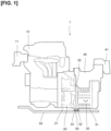
- Figure 1 is a front view of the drive device 1 for a vehicle of the present embodiment.
- the front face represents what is faced when the drive device is observed from the front in a vehicle longitudinal direction.
- the drive device 1 comprises an engine 10, a gearbox 20, an electric power generator 30 serving as a rotary electric machine, and a drive motor 40.
- An undercover 50 is provided on an underside of the drive device 1.
- the engine 10 causes the electric power generator 30 to generate electric power by rotatably driving the electric power generator 30.
- the electric power generated by the electric power generator 30 is accumulated in a battery (not shown).
- the drive motor 40 is a source of driving force for the vehicle and is driven by being supplied with the electric power of the battery.
- the gearbox 20 is a transmission device having a plurality of gears.
- the gearbox 20 allows the electric power generator 30 to generate electric power by transmitting rotation delivered from the engine 10 to the electric power generator 30.
- the gearbox 20 drives the vehicle by transmitting rotation delivered from the drive motor 40 to drive wheels (not shown).
- the drive motor 40 also functions as an electric power generator that performs electric power generation (regeneration) by receiving driving force provided by rotation of the drive wheels.
- the drive device 1 of the present embodiment may be used as a drive device for devices other than vehicles, e.g., various electric instruments or industrial machines.
- the electric power generator 30 is disposed in front of the drive motor 40 and slightly lower than the drive motor 40.
- An engine mount 11 is provided on an upper left part of the engine 10, and a motor mount 41 is provided on an upper right part of the drive motor 40.
- the drive device 1 is configured such that the engine 10, the gearbox 20, the electric power generator 30, and the drive motor 40 are integrated as a unit, and the drive device 1 is secured to the vehicle via the engine mount 11 and the motor mount 41.
- the engine mount 11 and the motor mount 41 are provided with pads made of rubber, etc., and vibration and shock transmitted between the vehicle and the drive device 1 are therefore damped.
- the undercover 50 is provided underneath the drive device 1.
- the undercover 50 is formed of a resin or another material so as to cover lower surfaces of the drive device 1 and other various components disposed in the lower part of the vehicle.
- the undercover 50 includes a protecting plate 55 (described hereinafter) and functions as a protecting member that protects the drive device 1.
- the gearbox 20 has a gearbox housing 21 in which a gear mechanism composed of a plurality of gears is accommodated.
- the interior of the gearbox housing 21 has a hollow tubular shape.
- Flange parts for linking to the engine 10, the electric power generator 30, and the drive motor 40 by bolt-fastening are formed protruding on a periphery of both end sides of the gearbox housing 21.
- the flange part facing the electric power generator 30, i.e., flange part on the right side of Fig. 1 is referred to particularly as a gearbox flange 22.
- the electric power generator 30 has a cylindrical electric power generator housing 31 that accommodates rotary electric machine components including a rotor, a stator, etc.
- An electric power generator flange 32 is formed protruding on a periphery of a left end side (gearbox side) of the electric power generator housing 31.
- the electric power generator 30 is connected to the gearbox 20 by using bolts to fasten the gearbox flange 22 of the gearbox 20 and the electric power generator flange 32 in a state of having been brought into contact with each other.
- the electric power generator 30 has a "cantilever" structure which does not include a mount that is secured to the vehicle, and in which only one side (the left side in Fig. 1 ) along the rotation axis direction is supported by the gearbox 20.
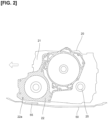
- Figure 2 is an explanatory drawing of a flange surface of the gearbox flange 22 of the gearbox 20, as seen along the direction of the rotation axis of the gearbox 20 (the width direction of the vehicle).
- the flange surface of the gearbox flange 22 (shown in hatching) has a plurality of bolt taps 22a for securing the electric power generator 30, as shown in Fig. 2 .
- the electric power generator flange 32 of the electric power generator 30 similarly has bolt holes, and the electric power generator 30 is secured to the gearbox 20 by inserting and fastening bolts in these bolt holes.
- the drive motor 40 and the gearbox 20 are similarly secured, as are the engine 10 and the gearbox 20.
- the gearbox 20 includes an axle hole 25 through which an axle is inserted, as shown in Fig. 2 .
- An axle (not shown) is connected to a final gear of the gearbox 20 in the axle hole 25.
- the gearbox 20 and the electric power generator 30 are connected by the gearbox flange 22 and the electric power generator flange 32 as previously described.
- external force means, for example, a load when a collision occurs between the drive device 1 and an obstacle such as a curb on the road surface.
- the undercover 50 is present on the underside of the drive device 1, and the undercover 50 is made of a resin and protects the drive device 1 against minor external force caused by shock from gravel, etc., during traveling, and easily deforms when subjected to a major external force. Therefore, when a major external force is delivered, the external force would be directly delivered underneath the drive device 1.
- the electric power generator 30 has a cantilever structure as previously described and does not include a mount that serves to dampen loads. Therefore, a load delivered to the lower surface of the connecting part 35 of the gearbox flange 22 and the electric power generator flange 32 acts without being damped and acts as force in a shearing direction between the gearbox flange 22 and the electric power generator flange 32. This sometimes results in loosening or twisting of the bolts securing the gearbox flange 22 and the electric power generator flange 32.
- the present embodiment is configured as follows so that no misalignment occurs between the gearbox 20 and the electric power generator 30 even if major external force is delivered.
- Figure 3 is an enlarged view of the vicinity of the connecting part of the gearbox 20 and the electric power generator 30 of the present embodiment, and is an explanatory drawing of the protecting plate 55.
- the flange surface of the gearbox flange 22 and a flange surface of the electric power generator flange 32 are in contact with each other.
- a bottom part (lower surface) of the gearbox flange 22 is formed so as to be positioned slightly lower than a bottom part (lower surface) of the electric power generator flange 32.
- the bottom part of the gearbox flange 22 and the bottom part of the electric power generator flange 32 are not flush with each other, but are configured so that the positions thereof in the height direction are different.
- the undercover 50 is a cover member that covers a lower surface of the drive device 1, and the protecting plate 55 is provided in a position of facing the connecting part 35 of the gearbox 20 and the electric power generator 30.
- the protecting plate 55 is disposed in a position near the front of the vehicle (see Fig. 2 ).
- the protecting plate 55 is formed of a material (e.g., steel, stainless steel, or another metal) more rigid than the undercover 50.
- the protecting plate 55 is bolted, welded, riveted, or otherwise secured to an upper surface of the undercover 50 facing the drive device 1.
- the protecting plate 55 is provided so as to face both the lower surface of the gearbox flange 22 and the lower surface of the electric power generator flange 32, as shown in Fig. 3 .
- the protecting plate 55 is disposed facing the electric power generator flange 32 in the direction in which the gearbox flange 22 and the electric power generator flange 32 are connected, and a length of the protecting plate 55 (indicated by letter B in Fig. 3 ) is greater than a length (thickness) of the electric power generator flange 32 (indicated by letter A in Fig. 3 ).
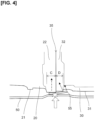
- Figure 4 is an explanatory drawing of behavior of the protecting plate 55 when major external force is delivered to the connecting part 35 of the gearbox flange 22 and the electric power generator flange 32.
- the protecting plate 55 first comes into contact with the gearbox flange 22. Due to the load from the external force, a right-side portion (the portion facing the electric power generator 30) of the protecting plate 55 deforms so as to bend with the corner of the gearbox flange 22 as a fulcrum, as shown in Fig. 4 .
- the right-side portion of the deformed protecting plate 55 collides with the corner of the electric power generator flange 32 or with the electric power generator housing 31 to the right of the electric power generator flange 32.
- the protecting plate 55 changes the direction of the load acting on the gearbox flange 22 (indicated by the single-dot-dash lined arrow in Fig. 4 ) and the direction of the load acting on the electric power generator flange 32 (indicated by the dotted line arrow in Fig. 4 ).
- the direction of the load delivered to the gearbox flange 22 and the direction of the load delivered to the electric power generator flange 32 being changed in the connecting part 35, the exertion of force in the shearing direction on the connecting part 35 of the gearbox flange 22 and the electric power generator flange 32 is minimized.
- the length (thickness) of the electric power generator flange 32 (indicated by letter D in Fig. 4 ) may be formed less than a length (thickness) of the gearbox flange 22 (indicated by letter C in Fig. 4 ). Due to such a configuration, the protecting plate 55 comes into contact with the gearbox flange 22 first and does not readily come directly into contact with the electric power generator flange 32 even when the protecting plate 55 deforms due to a load. The exertion of force in the shearing direction on the connecting part 35 of the gearbox flange 22 and the electric power generator flange 32 is thereby minimized.
- the structure for protecting the drive device 1 of the present embodiment is configured from the drive device 1 including the electric power generator (rotary electric machine) 30 and the gearbox 20, and the undercover 50 disposed underneath the drive device 1.
- the electric power generator 30 and the gearbox 20 are connected to each other by the electric power generator flange 32 of the electric power generator housing 31 and the gearbox flange 22 of the gearbox housing 21.
- the electric power generator flange 32 and the gearbox flange 22 are formed such that the lower surface of the gearbox flange 22 is positioned lower than the lower surface of the electric power generator flange 32.
- the undercover 50 includes the protecting plate 55, which is formed of a material more rigid than a material of the undercover 50.
- the protecting plate 55 is provided on the underside of the connecting part 35 of the electric power generator flange 32 and the gearbox flange 22, and is provided facing the connecting part 35.
- the protecting plate 55 comes into contact first with the lower surface of the gearbox flange 22 disposed lower than the lower surface of the electric power generator flange 32. It is thereby possible to change the direction of the load delivered to the gearbox flange 22 and the direction of the load delivered to the electric power generator flange 32 in the connecting part 35.
- the direct exertion of a load in the shearing direction between the gearbox flange 22 and the electric power generator flange 32 can be minimized; therefore, any incidence of loosening and twisting of the bolts secured to the electric power generator flange 32 and the gearbox flange 22 is minimized, and any incidence of problems in the transmission of motive power between the gearbox 20 and the electric power generator 30 can be minimized.
- the protecting plate 55 is disposed facing the electric power generator flange 32 and is formed longer than the length of the electric power generator flange 32 in the direction in which the electric power generator flange 32 and the gearbox flange 22 are connected. Due to such a configuration, external force from underneath causes the protecting plate 55 to come into contact first with a location other than the electric power generator flange 32. As a result, in the connecting part 35, the direction of the load delivered to the gearbox flange 22 and the direction of the load delivered to the electric power generator flange 32 can be reliably changed, and it is therefore possible to minimize the direct exertion of a load in the shearing direction between the gearbox flange 22 and the electric power generator flange 32.
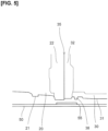
- Figure 5 is an explanatory drawing of the protecting plate 55 of a modification of the present embodiment, and Fig. 5 corresponds to Fig. 3 .
- a protruding part 38 extending toward the protecting plate 55 is formed in the electric power generator housing 31 in a different position from the electric power generator flange 32.
- the protruding part 38 is configured as a protrusion extending downward from a lower surface of the electric power generator housing 31, and is disposed in a position of facing the protecting plate 55.
- a lower-end surface of the protruding part 38 is disposed extending farther downward than the lower surface of the electric power generator flange 32, and is positioned at the same height or slightly higher than a lower-end surface of the gearbox flange 22.
- the electric power generator housing 31 includes a protruding part 38 extending downward from the lower surface of the electric power generator housing 31 in a different position from the electric power generator flange 32, where the protruding part faces the protecting plate 55.
- Figure 6 is an explanatory drawing of the protecting plate 55 of another modification of the present embodiment, and Fig. 6 corresponds to Fig. 3 .
- the protecting plate 55 has a close part 55a, where a location facing the gearbox flange 22 is closer than a location facing the electric power generator flange 32.
- the close part 55a is formed with greater thickness in a direction of plate pressure.
- the protecting plate 55 when observed from the front face, includes a close part 55a in which a plate thickness of the location facing the gearbox flange 22 is formed greater than a plate thickness of the location facing the electric power generator flange 32. In other words, a distance from the close part 55a of the protecting plate 55 to the gearbox flange 22 is less than a distance from the close part 55a to the electric power generator flange 32.
- the protecting plate 55 was disposed underneath and vehicle-forward of the electric power generator 30, but the protecting plate 55 may also be disposed underneath and vehicle-rearward of the electric power generator 30. Furthermore, when bottom surfaces of the gearbox flange 22 and the electric power generator flange 32 are not uniform in height (are inclined) along the vehicle longitudinal direction, the protecting plate 55 may be disposed at the position of the lowest surface.
- the protecting plate 55 When the protecting plate 55 is disposed vehicle-forward of the electric power generator, the protecting plate mainly protects against loads delivered when the vehicle is traveling forward.
- the protecting plate 55 When the protecting plate 55 is disposed vehicle-rearward of the electric power generator, the protecting plate mainly protects against loads delivered when the vehicle is traveling in reverse. Moreover, the protecting plate 55 may be disposed fully across the longitudinal direction of the electric power generator 30.
Landscapes
- Engineering & Computer Science (AREA)
- Mechanical Engineering (AREA)
- General Engineering & Computer Science (AREA)
- Chemical & Material Sciences (AREA)
- Combustion & Propulsion (AREA)
- Transportation (AREA)
- Arrangement Or Mounting Of Propulsion Units For Vehicles (AREA)
- Body Structure For Vehicles (AREA)
- Motor Or Generator Frames (AREA)
- Hybrid Electric Vehicles (AREA)
- General Details Of Gearings (AREA)
- Steering Controls (AREA)
Applications Claiming Priority (1)
| Application Number | Priority Date | Filing Date | Title |
|---|---|---|---|
| PCT/JP2020/022698 WO2021250779A1 (ja) | 2020-06-09 | 2020-06-09 | 駆動装置の保護構造 |
Publications (3)
| Publication Number | Publication Date |
|---|---|
| EP4163520A1 EP4163520A1 (en) | 2023-04-12 |
| EP4163520A4 EP4163520A4 (en) | 2023-07-26 |
| EP4163520B1 true EP4163520B1 (en) | 2023-12-27 |
Family
ID=78845455
Family Applications (1)
| Application Number | Title | Priority Date | Filing Date |
|---|---|---|---|
| EP20940114.0A Active EP4163520B1 (en) | 2020-06-09 | 2020-06-09 | Protective structure for drive device |
Country Status (7)
| Country | Link |
|---|---|
| US (1) | US11953084B2 (https=) |
| EP (1) | EP4163520B1 (https=) |
| JP (1) | JP7184212B2 (https=) |
| CN (1) | CN114144605B (https=) |
| BR (1) | BR112022002050A2 (https=) |
| MX (1) | MX2022001446A (https=) |
| WO (1) | WO2021250779A1 (https=) |
Families Citing this family (2)
| Publication number | Priority date | Publication date | Assignee | Title |
|---|---|---|---|---|
| JP7184212B2 (ja) * | 2020-06-09 | 2022-12-06 | 日産自動車株式会社 | 駆動装置の保護構造 |
| JP7361145B2 (ja) * | 2022-02-16 | 2023-10-13 | 本田技研工業株式会社 | 車両下部構造 |
Family Cites Families (39)
| Publication number | Priority date | Publication date | Assignee | Title |
|---|---|---|---|---|
| AT354863B (de) * | 1975-06-13 | 1980-02-11 | List Hans | Kraftfahrzeug mit einer schalldaemmenden kapsel fuer den motor bzw. die motor-getriebe -einheit |
| JPS61205843U (https=) * | 1985-06-14 | 1986-12-25 | ||
| JP3535047B2 (ja) | 1999-07-16 | 2004-06-07 | 日産車体株式会社 | Ff車用アンダーカバー |
| JP4353292B2 (ja) * | 2007-09-25 | 2009-10-28 | トヨタ自動車株式会社 | 電動車両 |
| JP2010000859A (ja) | 2008-06-19 | 2010-01-07 | Mazda Motor Corp | ハイブリッド電気自動車の駆動装置 |
| FR2950852B1 (fr) * | 2009-10-06 | 2011-12-16 | Renault Sa | Dispositif de protection contre les chocs d'un organe de vehicule automobile monte sous caisse |
| CN103153761B (zh) * | 2010-09-30 | 2015-08-26 | 本田技研工业株式会社 | 车身前部构造 |
| WO2012060195A1 (ja) * | 2010-11-02 | 2012-05-10 | 本田技研工業株式会社 | 電気自動車 |
| JP5970825B2 (ja) * | 2012-01-17 | 2016-08-17 | 三菱自動車工業株式会社 | アンダーカバー |
| EP2847496B1 (en) * | 2012-07-09 | 2021-06-16 | Eaton Intelligent Power Limited | Drive system |
| US8839901B1 (en) * | 2013-03-20 | 2014-09-23 | International Truck Intellectual Property Company, Llc | Transfer case skid shield |
| JP6020512B2 (ja) * | 2014-05-15 | 2016-11-02 | トヨタ紡織株式会社 | 車両用アンダーカバーの製造方法 |
| JP2016132326A (ja) * | 2015-01-16 | 2016-07-25 | トヨタ自動車株式会社 | 電気自動車、保持機構、及び電気自動車の製造方法 |
| US9505446B2 (en) * | 2015-04-15 | 2016-11-29 | Toyota Jidosha Kabushiki Kaisha | Powertrain unit |
| EP3199430A1 (en) * | 2016-01-27 | 2017-08-02 | Autoneum Management AG | Underbody panel having mounting points |
| JP6424873B2 (ja) * | 2016-10-11 | 2018-11-21 | トヨタ自動車株式会社 | 動力伝達装置の保護構造 |
| US10935123B2 (en) * | 2016-12-22 | 2021-03-02 | Siemens Aktiengesellschaft | Angle geared motor |
| JP6447642B2 (ja) * | 2017-01-16 | 2019-01-09 | マツダ株式会社 | 電動車両 |
| US20180215328A1 (en) * | 2017-01-31 | 2018-08-02 | Ford Global Technologies, Llc | Twin sheet belly pan and method of production |
| JP6819390B2 (ja) | 2017-03-22 | 2021-01-27 | トヨタ自動車株式会社 | 車両下部構造 |
| MX2019014766A (es) * | 2017-06-12 | 2020-02-07 | Unipres Corp | Estructura para acoplar una cubierta inferior a la carroceria del vehiculo. |
| JP6763828B2 (ja) * | 2017-06-27 | 2020-09-30 | 本田技研工業株式会社 | 車体アンダカバー構造 |
| DE102017214555B4 (de) * | 2017-08-21 | 2019-10-24 | Continental Automotive Gmbh | Rotor und elektrische Maschine |
| EP3483040B1 (en) * | 2017-11-02 | 2020-11-25 | Toyota Jidosha Kabushiki Kaisha | Vehicle front portion structure |
| JP6946997B2 (ja) * | 2017-12-13 | 2021-10-13 | トヨタ自動車株式会社 | 車両用のオイルパンガード |
| DE102018201805A1 (de) * | 2018-02-06 | 2019-08-08 | Bayerische Motoren Werke Aktiengesellschaft | Kraftfahrzeug mit elektrischem Hybridantrieb oder Elektroantrieb und einer Crashenergie-Aufnahmeeinrichtung |
| EP3539810A1 (en) * | 2018-03-13 | 2019-09-18 | FCA Italy S.p.A. | Electric vehicle with a modular structure |
| JP7006416B2 (ja) * | 2018-03-20 | 2022-01-24 | トヨタ自動車株式会社 | フロアアンダーカバー |
| EP3971065B1 (en) * | 2018-05-15 | 2023-12-06 | Volvo Car Corporation | Electric vehicle |
| JP7131400B2 (ja) * | 2019-01-16 | 2022-09-06 | トヨタ自動車株式会社 | 車両前部構造 |
| JP7156991B2 (ja) * | 2019-03-29 | 2022-10-19 | 本田技研工業株式会社 | サブフレーム構造 |
| WO2021220027A1 (ja) * | 2020-04-28 | 2021-11-04 | 日産自動車株式会社 | 電気自動車のフロア構造 |
| JP7184212B2 (ja) * | 2020-06-09 | 2022-12-06 | 日産自動車株式会社 | 駆動装置の保護構造 |
| JP7184851B2 (ja) * | 2020-07-28 | 2022-12-06 | 本田技研工業株式会社 | アンダカバー構造 |
| KR20220036618A (ko) * | 2020-09-16 | 2022-03-23 | 현대자동차주식회사 | 차량 충돌에너지 흡수시스템 |
| DE102020129748B4 (de) * | 2020-11-11 | 2022-12-01 | Bayerische Motoren Werke Aktiengesellschaft | Energiespeicher–Bodengruppe für einen elektrisch antreibbaren Personenkraftwagen |
| JP7585924B2 (ja) * | 2021-03-26 | 2024-11-19 | マツダ株式会社 | 電動車両の下部構造 |
| KR20230031729A (ko) * | 2021-08-27 | 2023-03-07 | 현대자동차주식회사 | 차량용 언더커버구조 |
| JP2023128140A (ja) * | 2022-03-03 | 2023-09-14 | 本田技研工業株式会社 | 車両下部構造 |
-
2020
- 2020-06-09 JP JP2021564847A patent/JP7184212B2/ja active Active
- 2020-06-09 US US17/630,752 patent/US11953084B2/en active Active
- 2020-06-09 BR BR112022002050A patent/BR112022002050A2/pt unknown
- 2020-06-09 MX MX2022001446A patent/MX2022001446A/es unknown
- 2020-06-09 EP EP20940114.0A patent/EP4163520B1/en active Active
- 2020-06-09 WO PCT/JP2020/022698 patent/WO2021250779A1/ja not_active Ceased
- 2020-06-09 CN CN202080052888.7A patent/CN114144605B/zh active Active
Also Published As
| Publication number | Publication date |
|---|---|
| US11953084B2 (en) | 2024-04-09 |
| EP4163520A1 (en) | 2023-04-12 |
| US20220260149A1 (en) | 2022-08-18 |
| CN114144605B (zh) | 2023-03-10 |
| EP4163520A4 (en) | 2023-07-26 |
| BR112022002050A2 (pt) | 2023-01-17 |
| JP7184212B2 (ja) | 2022-12-06 |
| MX2022001446A (es) | 2022-02-22 |
| WO2021250779A1 (ja) | 2021-12-16 |
| JPWO2021250779A1 (https=) | 2021-12-16 |
| CN114144605A (zh) | 2022-03-04 |
Similar Documents
| Publication | Publication Date | Title |
|---|---|---|
| EP1674316B1 (en) | Drive motor fixing structure and fixing method | |
| US11492044B2 (en) | Vehicle front structure | |
| JP5757283B2 (ja) | 電子機器の車載構造 | |
| JP4321199B2 (ja) | 駆動モータの取付構造 | |
| EP4163520B1 (en) | Protective structure for drive device | |
| EP3524496B1 (en) | Vehicle front end | |
| KR101786321B1 (ko) | 파워트레인 유닛 | |
| JP5381073B2 (ja) | 車載機器の搭載構造 | |
| CN111942157B (zh) | 驱动单元 | |
| JP2018111420A (ja) | 電力制御ユニットの車載構造 | |
| JP6945936B2 (ja) | 配線部品の保護構造 | |
| JPH09272459A (ja) | 電気自動車の車体前部構造 | |
| JP6873572B2 (ja) | 配線部品の保護構造 | |
| US12084831B2 (en) | Powertrain arrangement of a work machine and a work machine | |
| US12509154B2 (en) | Inverter mounting structure for vehicle | |
| JP5929749B2 (ja) | 車載機器の搭載構造 | |
| JP2007084041A (ja) | マスターシリンダー前端部構造 | |
| WO2019207985A1 (ja) | 駆動ユニット支持装置 | |
| US12109875B2 (en) | Electric vehicle powertrain arrangement | |
| JP2021046088A (ja) | バッテリプロテクタ | |
| CN211032154U (zh) | 车辆用动力单元的支撑结构 | |
| JP4546903B2 (ja) | 電気自動車のケーブル保護構造 | |
| JP2019093910A (ja) | 電動車両 | |
| US20250026407A1 (en) | Protective structure | |
| US12470112B2 (en) | Integrated unit |
Legal Events
| Date | Code | Title | Description |
|---|---|---|---|
| STAA | Information on the status of an ep patent application or granted ep patent |
Free format text: STATUS: THE INTERNATIONAL PUBLICATION HAS BEEN MADE |
|
| PUAI | Public reference made under article 153(3) epc to a published international application that has entered the european phase |
Free format text: ORIGINAL CODE: 0009012 |
|
| STAA | Information on the status of an ep patent application or granted ep patent |
Free format text: STATUS: REQUEST FOR EXAMINATION WAS MADE |
|
| 17P | Request for examination filed |
Effective date: 20220201 |
|
| AK | Designated contracting states |
Kind code of ref document: A1 Designated state(s): AL AT BE BG CH CY CZ DE DK EE ES FI FR GB GR HR HU IE IS IT LI LT LU LV MC MK MT NL NO PL PT RO RS SE SI SK SM TR |
|
| REG | Reference to a national code |
Ref country code: DE Ref legal event code: R079 Ipc: F16H0057020000 Ref country code: DE Ref legal event code: R079 Ref document number: 602020023630 Country of ref document: DE Free format text: PREVIOUS MAIN CLASS: F16H0057031000 Ipc: F16H0057020000 |
|
| A4 | Supplementary search report drawn up and despatched |
Effective date: 20230627 |
|
| RIC1 | Information provided on ipc code assigned before grant |
Ipc: B62D 25/20 20060101ALI20230621BHEP Ipc: F16H 57/02 20120101AFI20230621BHEP |
|
| DAV | Request for validation of the european patent (deleted) | ||
| DAX | Request for extension of the european patent (deleted) | ||
| GRAP | Despatch of communication of intention to grant a patent |
Free format text: ORIGINAL CODE: EPIDOSNIGR1 |
|
| STAA | Information on the status of an ep patent application or granted ep patent |
Free format text: STATUS: GRANT OF PATENT IS INTENDED |
|
| INTG | Intention to grant announced |
Effective date: 20231012 |
|
| GRAS | Grant fee paid |
Free format text: ORIGINAL CODE: EPIDOSNIGR3 |
|
| GRAA | (expected) grant |
Free format text: ORIGINAL CODE: 0009210 |
|
| STAA | Information on the status of an ep patent application or granted ep patent |
Free format text: STATUS: THE PATENT HAS BEEN GRANTED |
|
| AK | Designated contracting states |
Kind code of ref document: B1 Designated state(s): AL AT BE BG CH CY CZ DE DK EE ES FI FR GB GR HR HU IE IS IT LI LT LU LV MC MK MT NL NO PL PT RO RS SE SI SK SM TR |
|
| REG | Reference to a national code |
Ref country code: GB Ref legal event code: FG4D |
|
| REG | Reference to a national code |
Ref country code: CH Ref legal event code: EP |
|
| REG | Reference to a national code |
Ref country code: DE Ref legal event code: R096 Ref document number: 602020023630 Country of ref document: DE |
|
| REG | Reference to a national code |
Ref country code: IE Ref legal event code: FG4D |
|
| PG25 | Lapsed in a contracting state [announced via postgrant information from national office to epo] |
Ref country code: GR Free format text: LAPSE BECAUSE OF FAILURE TO SUBMIT A TRANSLATION OF THE DESCRIPTION OR TO PAY THE FEE WITHIN THE PRESCRIBED TIME-LIMIT Effective date: 20240328 |
|
| REG | Reference to a national code |
Ref country code: LT Ref legal event code: MG9D |
|
| PG25 | Lapsed in a contracting state [announced via postgrant information from national office to epo] |
Ref country code: LT Free format text: LAPSE BECAUSE OF FAILURE TO SUBMIT A TRANSLATION OF THE DESCRIPTION OR TO PAY THE FEE WITHIN THE PRESCRIBED TIME-LIMIT Effective date: 20231227 |
|
| PG25 | Lapsed in a contracting state [announced via postgrant information from national office to epo] |
Ref country code: ES Free format text: LAPSE BECAUSE OF FAILURE TO SUBMIT A TRANSLATION OF THE DESCRIPTION OR TO PAY THE FEE WITHIN THE PRESCRIBED TIME-LIMIT Effective date: 20231227 |
|
| PG25 | Lapsed in a contracting state [announced via postgrant information from national office to epo] |
Ref country code: LT Free format text: LAPSE BECAUSE OF FAILURE TO SUBMIT A TRANSLATION OF THE DESCRIPTION OR TO PAY THE FEE WITHIN THE PRESCRIBED TIME-LIMIT Effective date: 20231227 Ref country code: GR Free format text: LAPSE BECAUSE OF FAILURE TO SUBMIT A TRANSLATION OF THE DESCRIPTION OR TO PAY THE FEE WITHIN THE PRESCRIBED TIME-LIMIT Effective date: 20240328 Ref country code: FI Free format text: LAPSE BECAUSE OF FAILURE TO SUBMIT A TRANSLATION OF THE DESCRIPTION OR TO PAY THE FEE WITHIN THE PRESCRIBED TIME-LIMIT Effective date: 20231227 Ref country code: ES Free format text: LAPSE BECAUSE OF FAILURE TO SUBMIT A TRANSLATION OF THE DESCRIPTION OR TO PAY THE FEE WITHIN THE PRESCRIBED TIME-LIMIT Effective date: 20231227 Ref country code: BG Free format text: LAPSE BECAUSE OF FAILURE TO SUBMIT A TRANSLATION OF THE DESCRIPTION OR TO PAY THE FEE WITHIN THE PRESCRIBED TIME-LIMIT Effective date: 20240327 |
|
| REG | Reference to a national code |
Ref country code: NL Ref legal event code: MP Effective date: 20231227 |
|
| REG | Reference to a national code |
Ref country code: AT Ref legal event code: MK05 Ref document number: 1644800 Country of ref document: AT Kind code of ref document: T Effective date: 20231227 |
|
| PG25 | Lapsed in a contracting state [announced via postgrant information from national office to epo] |
Ref country code: NL Free format text: LAPSE BECAUSE OF FAILURE TO SUBMIT A TRANSLATION OF THE DESCRIPTION OR TO PAY THE FEE WITHIN THE PRESCRIBED TIME-LIMIT Effective date: 20231227 |
|
| PG25 | Lapsed in a contracting state [announced via postgrant information from national office to epo] |
Ref country code: SE Free format text: LAPSE BECAUSE OF FAILURE TO SUBMIT A TRANSLATION OF THE DESCRIPTION OR TO PAY THE FEE WITHIN THE PRESCRIBED TIME-LIMIT Effective date: 20231227 Ref country code: RS Free format text: LAPSE BECAUSE OF FAILURE TO SUBMIT A TRANSLATION OF THE DESCRIPTION OR TO PAY THE FEE WITHIN THE PRESCRIBED TIME-LIMIT Effective date: 20231227 Ref country code: NO Free format text: LAPSE BECAUSE OF FAILURE TO SUBMIT A TRANSLATION OF THE DESCRIPTION OR TO PAY THE FEE WITHIN THE PRESCRIBED TIME-LIMIT Effective date: 20240327 Ref country code: NL Free format text: LAPSE BECAUSE OF FAILURE TO SUBMIT A TRANSLATION OF THE DESCRIPTION OR TO PAY THE FEE WITHIN THE PRESCRIBED TIME-LIMIT Effective date: 20231227 Ref country code: LV Free format text: LAPSE BECAUSE OF FAILURE TO SUBMIT A TRANSLATION OF THE DESCRIPTION OR TO PAY THE FEE WITHIN THE PRESCRIBED TIME-LIMIT Effective date: 20231227 Ref country code: HR Free format text: LAPSE BECAUSE OF FAILURE TO SUBMIT A TRANSLATION OF THE DESCRIPTION OR TO PAY THE FEE WITHIN THE PRESCRIBED TIME-LIMIT Effective date: 20231227 |
|
| PG25 | Lapsed in a contracting state [announced via postgrant information from national office to epo] |
Ref country code: IS Free format text: LAPSE BECAUSE OF FAILURE TO SUBMIT A TRANSLATION OF THE DESCRIPTION OR TO PAY THE FEE WITHIN THE PRESCRIBED TIME-LIMIT Effective date: 20240427 |
|
| PG25 | Lapsed in a contracting state [announced via postgrant information from national office to epo] |
Ref country code: CZ Free format text: LAPSE BECAUSE OF FAILURE TO SUBMIT A TRANSLATION OF THE DESCRIPTION OR TO PAY THE FEE WITHIN THE PRESCRIBED TIME-LIMIT Effective date: 20231227 Ref country code: AT Free format text: LAPSE BECAUSE OF FAILURE TO SUBMIT A TRANSLATION OF THE DESCRIPTION OR TO PAY THE FEE WITHIN THE PRESCRIBED TIME-LIMIT Effective date: 20231227 |
|
| PG25 | Lapsed in a contracting state [announced via postgrant information from national office to epo] |
Ref country code: SK Free format text: LAPSE BECAUSE OF FAILURE TO SUBMIT A TRANSLATION OF THE DESCRIPTION OR TO PAY THE FEE WITHIN THE PRESCRIBED TIME-LIMIT Effective date: 20231227 |
|
| PG25 | Lapsed in a contracting state [announced via postgrant information from national office to epo] |
Ref country code: SM Free format text: LAPSE BECAUSE OF FAILURE TO SUBMIT A TRANSLATION OF THE DESCRIPTION OR TO PAY THE FEE WITHIN THE PRESCRIBED TIME-LIMIT Effective date: 20231227 Ref country code: SK Free format text: LAPSE BECAUSE OF FAILURE TO SUBMIT A TRANSLATION OF THE DESCRIPTION OR TO PAY THE FEE WITHIN THE PRESCRIBED TIME-LIMIT Effective date: 20231227 Ref country code: RO Free format text: LAPSE BECAUSE OF FAILURE TO SUBMIT A TRANSLATION OF THE DESCRIPTION OR TO PAY THE FEE WITHIN THE PRESCRIBED TIME-LIMIT Effective date: 20231227 Ref country code: IT Free format text: LAPSE BECAUSE OF FAILURE TO SUBMIT A TRANSLATION OF THE DESCRIPTION OR TO PAY THE FEE WITHIN THE PRESCRIBED TIME-LIMIT Effective date: 20231227 Ref country code: IS Free format text: LAPSE BECAUSE OF FAILURE TO SUBMIT A TRANSLATION OF THE DESCRIPTION OR TO PAY THE FEE WITHIN THE PRESCRIBED TIME-LIMIT Effective date: 20240427 Ref country code: EE Free format text: LAPSE BECAUSE OF FAILURE TO SUBMIT A TRANSLATION OF THE DESCRIPTION OR TO PAY THE FEE WITHIN THE PRESCRIBED TIME-LIMIT Effective date: 20231227 Ref country code: CZ Free format text: LAPSE BECAUSE OF FAILURE TO SUBMIT A TRANSLATION OF THE DESCRIPTION OR TO PAY THE FEE WITHIN THE PRESCRIBED TIME-LIMIT Effective date: 20231227 Ref country code: AT Free format text: LAPSE BECAUSE OF FAILURE TO SUBMIT A TRANSLATION OF THE DESCRIPTION OR TO PAY THE FEE WITHIN THE PRESCRIBED TIME-LIMIT Effective date: 20231227 |
|
| PG25 | Lapsed in a contracting state [announced via postgrant information from national office to epo] |
Ref country code: PT Free format text: LAPSE BECAUSE OF FAILURE TO SUBMIT A TRANSLATION OF THE DESCRIPTION OR TO PAY THE FEE WITHIN THE PRESCRIBED TIME-LIMIT Effective date: 20240429 Ref country code: PL Free format text: LAPSE BECAUSE OF FAILURE TO SUBMIT A TRANSLATION OF THE DESCRIPTION OR TO PAY THE FEE WITHIN THE PRESCRIBED TIME-LIMIT Effective date: 20231227 |
|
| PG25 | Lapsed in a contracting state [announced via postgrant information from national office to epo] |
Ref country code: PT Free format text: LAPSE BECAUSE OF FAILURE TO SUBMIT A TRANSLATION OF THE DESCRIPTION OR TO PAY THE FEE WITHIN THE PRESCRIBED TIME-LIMIT Effective date: 20240429 Ref country code: PL Free format text: LAPSE BECAUSE OF FAILURE TO SUBMIT A TRANSLATION OF THE DESCRIPTION OR TO PAY THE FEE WITHIN THE PRESCRIBED TIME-LIMIT Effective date: 20231227 |
|
| REG | Reference to a national code |
Ref country code: DE Ref legal event code: R097 Ref document number: 602020023630 Country of ref document: DE |
|
| PG25 | Lapsed in a contracting state [announced via postgrant information from national office to epo] |
Ref country code: DK Free format text: LAPSE BECAUSE OF FAILURE TO SUBMIT A TRANSLATION OF THE DESCRIPTION OR TO PAY THE FEE WITHIN THE PRESCRIBED TIME-LIMIT Effective date: 20231227 |
|
| PG25 | Lapsed in a contracting state [announced via postgrant information from national office to epo] |
Ref country code: DK Free format text: LAPSE BECAUSE OF FAILURE TO SUBMIT A TRANSLATION OF THE DESCRIPTION OR TO PAY THE FEE WITHIN THE PRESCRIBED TIME-LIMIT Effective date: 20231227 |
|
| PLBE | No opposition filed within time limit |
Free format text: ORIGINAL CODE: 0009261 |
|
| STAA | Information on the status of an ep patent application or granted ep patent |
Free format text: STATUS: NO OPPOSITION FILED WITHIN TIME LIMIT |
|
| 26N | No opposition filed |
Effective date: 20240930 |
|
| PG25 | Lapsed in a contracting state [announced via postgrant information from national office to epo] |
Ref country code: MC Free format text: LAPSE BECAUSE OF FAILURE TO SUBMIT A TRANSLATION OF THE DESCRIPTION OR TO PAY THE FEE WITHIN THE PRESCRIBED TIME-LIMIT Effective date: 20231227 |
|
| REG | Reference to a national code |
Ref country code: CH Ref legal event code: PL |
|
| PG25 | Lapsed in a contracting state [announced via postgrant information from national office to epo] |
Ref country code: LU Free format text: LAPSE BECAUSE OF NON-PAYMENT OF DUE FEES Effective date: 20240609 |
|
| PG25 | Lapsed in a contracting state [announced via postgrant information from national office to epo] |
Ref country code: IE Free format text: LAPSE BECAUSE OF NON-PAYMENT OF DUE FEES Effective date: 20240609 |
|
| PG25 | Lapsed in a contracting state [announced via postgrant information from national office to epo] |
Ref country code: SI Free format text: LAPSE BECAUSE OF FAILURE TO SUBMIT A TRANSLATION OF THE DESCRIPTION OR TO PAY THE FEE WITHIN THE PRESCRIBED TIME-LIMIT Effective date: 20231227 Ref country code: BE Free format text: LAPSE BECAUSE OF NON-PAYMENT OF DUE FEES Effective date: 20240630 Ref country code: CH Free format text: LAPSE BECAUSE OF NON-PAYMENT OF DUE FEES Effective date: 20240630 |
|
| REG | Reference to a national code |
Ref country code: BE Ref legal event code: MM Effective date: 20240630 |
|
| PGFP | Annual fee paid to national office [announced via postgrant information from national office to epo] |
Ref country code: DE Payment date: 20250520 Year of fee payment: 6 |
|
| PGFP | Annual fee paid to national office [announced via postgrant information from national office to epo] |
Ref country code: GB Payment date: 20250520 Year of fee payment: 6 |
|
| PGFP | Annual fee paid to national office [announced via postgrant information from national office to epo] |
Ref country code: FR Payment date: 20250521 Year of fee payment: 6 |
|
| PG25 | Lapsed in a contracting state [announced via postgrant information from national office to epo] |
Ref country code: CY Free format text: LAPSE BECAUSE OF FAILURE TO SUBMIT A TRANSLATION OF THE DESCRIPTION OR TO PAY THE FEE WITHIN THE PRESCRIBED TIME-LIMIT; INVALID AB INITIO Effective date: 20200609 |
|
| PG25 | Lapsed in a contracting state [announced via postgrant information from national office to epo] |
Ref country code: HU Free format text: LAPSE BECAUSE OF FAILURE TO SUBMIT A TRANSLATION OF THE DESCRIPTION OR TO PAY THE FEE WITHIN THE PRESCRIBED TIME-LIMIT; INVALID AB INITIO Effective date: 20200609 |