EP4159513B1 - Struktur zur entladung von batteriekühlluft - Google Patents
Struktur zur entladung von batteriekühlluft Download PDFInfo
- Publication number
- EP4159513B1 EP4159513B1 EP20938009.6A EP20938009A EP4159513B1 EP 4159513 B1 EP4159513 B1 EP 4159513B1 EP 20938009 A EP20938009 A EP 20938009A EP 4159513 B1 EP4159513 B1 EP 4159513B1
- Authority
- EP
- European Patent Office
- Prior art keywords
- concave portion
- floor
- vehicle
- battery
- exhaust duct
- Prior art date
- Legal status (The legal status is an assumption and is not a legal conclusion. Google has not performed a legal analysis and makes no representation as to the accuracy of the status listed.)
- Active
Links
Images


Classifications
-
- B—PERFORMING OPERATIONS; TRANSPORTING
- B60—VEHICLES IN GENERAL
- B60K—ARRANGEMENT OR MOUNTING OF PROPULSION UNITS OR OF TRANSMISSIONS IN VEHICLES; ARRANGEMENT OR MOUNTING OF PLURAL DIVERSE PRIME-MOVERS IN VEHICLES; AUXILIARY DRIVES FOR VEHICLES; INSTRUMENTATION OR DASHBOARDS FOR VEHICLES; ARRANGEMENTS IN CONNECTION WITH COOLING, AIR INTAKE, GAS EXHAUST OR FUEL SUPPLY OF PROPULSION UNITS IN VEHICLES
- B60K11/00—Arrangement in connection with cooling of propulsion units
- B60K11/06—Arrangement in connection with cooling of propulsion units with air cooling
-
- B—PERFORMING OPERATIONS; TRANSPORTING
- B62—LAND VEHICLES FOR TRAVELLING OTHERWISE THAN ON RAILS
- B62D—MOTOR VEHICLES; TRAILERS
- B62D25/00—Superstructure or monocoque structure sub-units; Parts or details thereof not otherwise provided for
- B62D25/20—Floors or bottom sub-units
-
- H—ELECTRICITY
- H01—ELECTRIC ELEMENTS
- H01M—PROCESSES OR MEANS, e.g. BATTERIES, FOR THE DIRECT CONVERSION OF CHEMICAL ENERGY INTO ELECTRICAL ENERGY
- H01M10/00—Secondary cells; Manufacture thereof
- H01M10/60—Heating or cooling; Temperature control
- H01M10/61—Types of temperature control
- H01M10/613—Cooling or keeping cold
-
- H—ELECTRICITY
- H01—ELECTRIC ELEMENTS
- H01M—PROCESSES OR MEANS, e.g. BATTERIES, FOR THE DIRECT CONVERSION OF CHEMICAL ENERGY INTO ELECTRICAL ENERGY
- H01M10/00—Secondary cells; Manufacture thereof
- H01M10/60—Heating or cooling; Temperature control
- H01M10/62—Heating or cooling; Temperature control specially adapted for specific applications
- H01M10/625—Vehicles
-
- H—ELECTRICITY
- H01—ELECTRIC ELEMENTS
- H01M—PROCESSES OR MEANS, e.g. BATTERIES, FOR THE DIRECT CONVERSION OF CHEMICAL ENERGY INTO ELECTRICAL ENERGY
- H01M10/00—Secondary cells; Manufacture thereof
- H01M10/60—Heating or cooling; Temperature control
- H01M10/65—Means for temperature control structurally associated with the cells
- H01M10/656—Means for temperature control structurally associated with the cells characterised by the type of heat-exchange fluid
- H01M10/6561—Gases
-
- B—PERFORMING OPERATIONS; TRANSPORTING
- B60—VEHICLES IN GENERAL
- B60K—ARRANGEMENT OR MOUNTING OF PROPULSION UNITS OR OF TRANSMISSIONS IN VEHICLES; ARRANGEMENT OR MOUNTING OF PLURAL DIVERSE PRIME-MOVERS IN VEHICLES; AUXILIARY DRIVES FOR VEHICLES; INSTRUMENTATION OR DASHBOARDS FOR VEHICLES; ARRANGEMENTS IN CONNECTION WITH COOLING, AIR INTAKE, GAS EXHAUST OR FUEL SUPPLY OF PROPULSION UNITS IN VEHICLES
- B60K1/00—Arrangement or mounting of electrical propulsion units
- B60K1/04—Arrangement or mounting of electrical propulsion units of the electric storage means for propulsion
-
- B—PERFORMING OPERATIONS; TRANSPORTING
- B60—VEHICLES IN GENERAL
- B60K—ARRANGEMENT OR MOUNTING OF PROPULSION UNITS OR OF TRANSMISSIONS IN VEHICLES; ARRANGEMENT OR MOUNTING OF PLURAL DIVERSE PRIME-MOVERS IN VEHICLES; AUXILIARY DRIVES FOR VEHICLES; INSTRUMENTATION OR DASHBOARDS FOR VEHICLES; ARRANGEMENTS IN CONNECTION WITH COOLING, AIR INTAKE, GAS EXHAUST OR FUEL SUPPLY OF PROPULSION UNITS IN VEHICLES
- B60K13/00—Arrangement in connection with combustion air intake or gas exhaust of propulsion units
- B60K13/04—Arrangement in connection with combustion air intake or gas exhaust of propulsion units concerning exhaust
-
- B—PERFORMING OPERATIONS; TRANSPORTING
- B60—VEHICLES IN GENERAL
- B60K—ARRANGEMENT OR MOUNTING OF PROPULSION UNITS OR OF TRANSMISSIONS IN VEHICLES; ARRANGEMENT OR MOUNTING OF PLURAL DIVERSE PRIME-MOVERS IN VEHICLES; AUXILIARY DRIVES FOR VEHICLES; INSTRUMENTATION OR DASHBOARDS FOR VEHICLES; ARRANGEMENTS IN CONNECTION WITH COOLING, AIR INTAKE, GAS EXHAUST OR FUEL SUPPLY OF PROPULSION UNITS IN VEHICLES
- B60K1/00—Arrangement or mounting of electrical propulsion units
- B60K2001/003—Arrangement or mounting of electrical propulsion units with means for cooling the electrical propulsion units
- B60K2001/005—Arrangement or mounting of electrical propulsion units with means for cooling the electrical propulsion units the electric storage means
-
- B—PERFORMING OPERATIONS; TRANSPORTING
- B60—VEHICLES IN GENERAL
- B60K—ARRANGEMENT OR MOUNTING OF PROPULSION UNITS OR OF TRANSMISSIONS IN VEHICLES; ARRANGEMENT OR MOUNTING OF PLURAL DIVERSE PRIME-MOVERS IN VEHICLES; AUXILIARY DRIVES FOR VEHICLES; INSTRUMENTATION OR DASHBOARDS FOR VEHICLES; ARRANGEMENTS IN CONNECTION WITH COOLING, AIR INTAKE, GAS EXHAUST OR FUEL SUPPLY OF PROPULSION UNITS IN VEHICLES
- B60K1/00—Arrangement or mounting of electrical propulsion units
- B60K1/04—Arrangement or mounting of electrical propulsion units of the electric storage means for propulsion
- B60K2001/0405—Arrangement or mounting of electrical propulsion units of the electric storage means for propulsion characterised by their position
- B60K2001/0422—Arrangement under the front seats
-
- B—PERFORMING OPERATIONS; TRANSPORTING
- B60—VEHICLES IN GENERAL
- B60K—ARRANGEMENT OR MOUNTING OF PROPULSION UNITS OR OF TRANSMISSIONS IN VEHICLES; ARRANGEMENT OR MOUNTING OF PLURAL DIVERSE PRIME-MOVERS IN VEHICLES; AUXILIARY DRIVES FOR VEHICLES; INSTRUMENTATION OR DASHBOARDS FOR VEHICLES; ARRANGEMENTS IN CONNECTION WITH COOLING, AIR INTAKE, GAS EXHAUST OR FUEL SUPPLY OF PROPULSION UNITS IN VEHICLES
- B60K1/00—Arrangement or mounting of electrical propulsion units
- B60K1/04—Arrangement or mounting of electrical propulsion units of the electric storage means for propulsion
- B60K2001/0405—Arrangement or mounting of electrical propulsion units of the electric storage means for propulsion characterised by their position
- B60K2001/0427—Arrangement between the seats
-
- B—PERFORMING OPERATIONS; TRANSPORTING
- B60—VEHICLES IN GENERAL
- B60K—ARRANGEMENT OR MOUNTING OF PROPULSION UNITS OR OF TRANSMISSIONS IN VEHICLES; ARRANGEMENT OR MOUNTING OF PLURAL DIVERSE PRIME-MOVERS IN VEHICLES; AUXILIARY DRIVES FOR VEHICLES; INSTRUMENTATION OR DASHBOARDS FOR VEHICLES; ARRANGEMENTS IN CONNECTION WITH COOLING, AIR INTAKE, GAS EXHAUST OR FUEL SUPPLY OF PROPULSION UNITS IN VEHICLES
- B60K1/00—Arrangement or mounting of electrical propulsion units
- B60K1/04—Arrangement or mounting of electrical propulsion units of the electric storage means for propulsion
- B60K2001/0405—Arrangement or mounting of electrical propulsion units of the electric storage means for propulsion characterised by their position
- B60K2001/0438—Arrangement under the floor
-
- H—ELECTRICITY
- H01—ELECTRIC ELEMENTS
- H01M—PROCESSES OR MEANS, e.g. BATTERIES, FOR THE DIRECT CONVERSION OF CHEMICAL ENERGY INTO ELECTRICAL ENERGY
- H01M2220/00—Batteries for particular applications
- H01M2220/20—Batteries in motive systems, e.g. vehicle, ship, plane
-
- Y—GENERAL TAGGING OF NEW TECHNOLOGICAL DEVELOPMENTS; GENERAL TAGGING OF CROSS-SECTIONAL TECHNOLOGIES SPANNING OVER SEVERAL SECTIONS OF THE IPC; TECHNICAL SUBJECTS COVERED BY FORMER USPC CROSS-REFERENCE ART COLLECTIONS [XRACs] AND DIGESTS
- Y02—TECHNOLOGIES OR APPLICATIONS FOR MITIGATION OR ADAPTATION AGAINST CLIMATE CHANGE
- Y02E—REDUCTION OF GREENHOUSE GAS [GHG] EMISSIONS, RELATED TO ENERGY GENERATION, TRANSMISSION OR DISTRIBUTION
- Y02E60/00—Enabling technologies; Technologies with a potential or indirect contribution to GHG emissions mitigation
- Y02E60/10—Energy storage using batteries
Definitions
- the present invention relates to a battery cooling air discharge structure.
- Hybrid cars are equipped with an engine and a motor, and are structured to be used selectively.
- Hybrid cars and other vehicles are equipped with a battery.
- the battery When a battery is installed in the vehicle, the battery must be cooled.
- the prior art includes attempts to cool the battery by means of an arrangement of air intake ducts and exhaust ducts (see Patent Document 1).
- Patent Document 2 discloses a battery cooling air discharge structure comprising: a floor panel constituting a lower part of a vehicle body of a vehicle and enabling placement of a battery; a floor arranged above the floor panel to allow placement of the battery between the floor and the floor panel; a plurality of rows of seats arranged on the floor; and an exhaust duct configured to discharge battery cooling air, the exhaust duct having an exhaust port located between the floor and a seating part of a rear seat that constitutes the seats.
- the inventors have focused on the fact that as the sound of the air required for cooling the battery grows louder, the noise of the air flow increases, making it difficult to suppress the sound due to the increased sound of the flowing air, and have conducted extensive studies on this problem.
- an object of at least one embodiment of the present invention is to provide a battery cooling air discharge structure that can suppress noise even if the amount of cooling air that is required for the battery becomes relatively high.
- orientation is indicated by the use of arrows represented by X, Y, and Z (coordinate system). That is, the "Z direction” is the vertical direction, the "X direction” is orthogonal to the Z direction and parallel to the horizontal plane, and the “Y direction” is orthogonal to the Z direction and parallel to the horizontal plane (direction orthogonal to the X direction).
- the direction of the arrow indicated by X represents the front-rear direction of vehicle 100, where plus indicates rear to front.
- Y represents the width direction of the vehicle 100, where plus indicates rightward.
- Z represents the height direction of the vehicle 100, where plus indicates upward.
- the vehicle 100 equipped with the battery cooling air discharge structure may be a vehicle, such as a hybrid electric vehicle (HEV) that uses a combination of an internal combustion engine and a battery-driven motor as a driving source, an electric vehicle (EV) that travels by means of a battery-driven motor, and the like.
- HEV hybrid electric vehicle
- EV electric vehicle
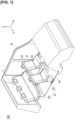
- the vehicle 100 comprises vehicle body B, seats 10, a floor consisting of a floor panel top portion 40 and a floor panel bottom portion fp, a battery 50, air intake ducts 60, a connecting duct 70, an exhaust fan 80, and an exhaust duct 90.
- a floor consisting of a floor panel top portion 40 and a floor panel bottom portion fp
- a battery 50 air intake ducts 60
- a connecting duct 70 a connecting duct 70
- an exhaust fan 80 an exhaust duct 90.
- the vehicle body B constitutes a framework that separates the passenger and luggage areas of the vehicle 100 from the outside.
- the vehicle body B of the vehicle 100 is configured as a compact car, such as a hatchback in the present embodiment, the type of vehicle (the shape and structure of the vehicle body B) is not particularly limited as long as the vehicle has structures that are the same as the seats 10, floor (floor panel top portion 40 and floor panel bottom portion fp), and the exhaust duct 90, described further below.
- the lower part of the vehicle 100 is provided with the floor panel bottom portion fp on which the battery 50, described further below, can be placed.
- the seats 10 are configured to be installed on the floor panel top portion 40 of the vehicle 100 in a plurality of rows.
- the seats 10, as seen from the front include front seats 20 that correspond to a first row of seats, and a rear seat 30 that corresponds to a second row of seats.
- the front seats 20 are installed to be movable at least in the front-rear direction X relative to the floor panel top portion 40.
- the front seats 20 include a backrest 21 against which an occupant's back can be rested, a seating part 22 on which the occupant's buttocks can be seated, and a headrest 23 on which the occupant's head can be rested.
- the front seats 20 are provided with independent driver and passenger seats.
- a luggage space L (also called luggage room or cargo area) connected to the passenger compartment is provided behind the rear seat 30.
- the rear seat 30 includes a backrest 31, a seating part 32, and headrests 33.
- the rear seat 30 is configured as a so-called bench seat, in which the left and right seats are connected.
- the backrest 31 and the seating part 32 are configured such that the backs and buttocks of a plurality of occupants can be placed on the rear seat 30.
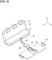
- the underside of the seating part 32 has a notch 34 in the height direction Z.
- the notch 34 has a concave shape, as shown in Figures 6 , 7 , etc.
- the concave shape of the notch 34 is configured to face downward in the height direction Z.
- the notch 34 has a first concave portion 35, an enlarged portion 36, a second concave portion 37, a third concave portion 38, and a convex portion 39.
- the first concave portion 35 is configured to allow the adjacent placement of an exhaust port 94 of the exhaust duct 90.
- the first concave portion 35 is provided on the front side of the seating part 32 in the front-rear direction X.
- the first concave portion 35 is configured to be formed to extend through to a front end portion f of the seating part 32.
- the exhaust duct 90 described further below, can be disposed below the seating part 32 in the height direction Z, the first concave portion 35 need not be formed to extend through to front end portion f of the seating part 32.
- the enlarged portion 36 is provided continuous with the first concave portion 35 behind the first concave portion 35 in the front-rear direction X.
- the enlarged portion 36 is configured such that that the cross-sectional shape of the notch from the first concave portion 35 is enlarged in the front-rear direction X.
- the enlarged portion 36 is configured such that the shape of the notch in the lower surface of the seating part 32 leads from the first concave portion 35 to the second concave portion 37 and the third concave portion 38 rearward in the front-rear direction X.
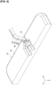
- the second concave portion 37 and the third concave portion 38 are provided in a continuous (connected) manner from the enlarged portion 36. As shown in Figure 7 , the second concave portion 37 and the third concave portion 38 are configured to extend substantially linearly to rear end portion r of the seating part 32 in the front-rear direction X of the vehicle 100.
- the second concave portion 37 and the third concave portion 38 preferably have the same cross-sectional shapes of the concave portions.
- the shapes are not extremely different, there may be slight differences in the cross-sectional shapes (for example, one may be a perfect circle while the other is an ellipse, or, in the case that the cross-sectional shapes are rectangular, the aspect ratio (length-to-width ratio) of the rectangular cross section may be different).
- the convex portion 39 bifurcates the notch connected to the enlarged portion 36 into the second concave portion 37 and the third concave portion 38.
- the position of the convex portion 39 is between the second concave portion 37 and the third concave portion 38 in the width direction Y in the present embodiment.
- air from the exhaust port 94 of the exhaust duct 90 can be directed along the first concave portion 35 and the enlarged portion 36, to the second concave portion 37 and the third concave portion 38, which correspond to branch flow paths, and from there into the luggage space L.
- the convex portion 39 can be positioned the buttocks (hip point) of the occupant in the rear seat 30.
- the convex portion 39 may be referred to as a pad, from the standpoint of being able to support the occupant's hip area.
- the floor panel top portion 40 is arranged above the floor panel bottom portion fp in the height direction Z.
- the floor panel top portion 40 is configured to allow the battery 50 to be positioned between the floor panel top and the floor panel bottom portion fp.
- the floor panel top portion 40 constitutes the lower part of the vehicle cabin of the vehicle 100. A carpet, floor mats, etc., can be placed on the floor panel top portion 40.
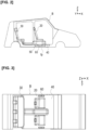
- the floor panel top portion 40 has a horizontal portion 41, a raised portion 42, and rising portions 43, 44.
- the horizontal portion 41 is the part of the vehicle cabin where the occupants' feet can be placed, and where the above-described carpet, etc., can be installed.
- the raised portion 42 is provided in the central area (middle portion) of the horizontal portion 41 in the width direction Y.
- the raised portion 42 is made higher than the horizontal portion 41 in the height direction Z in order to arrange thereunder the exhaust fan 80, etc., of the battery 50, described further below.
- the rising portions 43, 44 are positioned behind the horizontal portion 41 and the raised portion 42 in the front-rear direction X, and are positioned in the area below the seating part 32 of the rear seat 30.
- the rising portions 43, 44 are formed such that the height in the height direction Z gradually increases rearward in the front-rear direction X relative to the horizontal portion 41.
- the rising portion 44 is arranged such that the exhaust duct 90 is not exposed to the vehicle cabin (passenger compartment).
- the rising portions 44 is formed so as to rise higher in the height direction Z than the rising portion 43 below the seating part 32.
- Figure 5 which corresponds to the configuration described below, corresponds to Figure 4 without the floor panel top portion 40.
- the battery 50 is an energy storage device that supplies electrical energy to a motor, not shown, and is charged by the driving force of the engine and the recovery of regenerative energy. As shown in Figure 2 , in the present embodiment, the battery 50 is configured to be located near the lower part of the front seats 20 of the seats 10.
- the air intake ducts 60 are configured for the intake of air and other gases used for cooling the battery 50.
- the air intake ducts 60 are configured to be located near the lower part of the front seats 20 of the seats 10 and outwardly in the width direction Y from the battery 50.
- the openings of the air intake ducts 60 may be located in essentially the same plane (same height) as the horizontal portion 41 of the floor panel top portion 40.
- the connecting duct 70 is configured for taking in air and other gases that flow in from the air intake duct 60 and pass through the battery 50.
- the connecting duct 70 is arranged between the battery 50 and the exhaust fan 80 in the front-rear direction X.
- the connecting duct 70 can be arranged essentially in the center in the width direction Y.
- the connecting duct 70 can be arranged to extend rearward from the connecting portion with the battery 50 in the front-rear direction X.
- the exhaust fan 80 generates air for cooling the battery 50.
- the exhaust fan 80 can be composed of a sirocco-type centrifugal fan, or the like.
- the intake port of the exhaust fan 80 can be connected to the connecting duct 70.
- the exhaust duct 90 is configured to be able to discharge the air that has cooled the battery 50.
- the exhaust duct 90 is arranged between the floor panel bottom portion fp and the seating part 32 of the rear seat 30 that constitutes the seats 10.
- the exhaust duct 90 is arranged underneath the floor panel top portion 40; one end of the exhaust duct is connected to the exhaust port of the exhaust fan 80. The other end of the exhaust duct is arranged adjacent to the lower surface of the rear seat 30.
- the exhaust duct 90 includes a floor proximity portion 91, a rising portion 92, a seat proximity portion 93, and the exhaust port 94.
- the floor proximity portion 91 is connected to the exhaust port of the exhaust fan 80 and is located adjacent to the floor panel top portion 40.
- the floor proximity portion 91 is configured in the form of a cavity extending essentially linearly along the front-rear direction X of the vehicle 100.
- the floor proximity portion 91 is configured such that an approximately rectangular cross section with rounded corners extending linearly in the front-rear direction X.
- the rising portion 92 is shaped to connect the floor proximity portion 91 and the seat proximity portion 93.
- the rising portion 92 is configured to extend along the height direction Z.
- the rising portion 92 is configured as a shape that extends linearly not only in the height direction Z but also in the front-rear direction X and the width direction Y.
- the specific shape of the rising portion 92 is not limited in this way, and, in addition to the foregoing, may be shaped to extend linearly only in the height direction Z, for example.
- the seat proximity portion 93 is configured to be disposed at a different height than the height of the floor proximity portion 91 in the height direction Z, specifically, at a higher position than the floor proximity portion 91.
- the seat proximity portion 93 is configured to be located closer than the floor proximity portion 91 to the lower surface of the seating part 32 of the rear seat 30.
- the exhaust port 94 is configured to be located between the horizontal portion 41 of the floor panel top portion 40 and the seating part 32 of the rear seat 30 constituting the seats 10.
- the exhaust port 94 is configured as an opening at the end of the seat proximity portion 93.
- the exhaust port 94 is configured to be arranged adjacent to the notch 34 of the seating part 32 of the rear seat 30.
- the exhaust port 94 is positioned in front of the rear end portion r of the seating part 32 in the front-rear direction X of the vehicle 100.
- the exhaust port 94 is configured to be positioned in front of the enlarged portion 36 in the front-rear direction X of the vehicle (see Figure 7 ).
- the battery cooling air discharge structure includes the floor panel bottom portion fp, the floor panel top portion 40, the seats 10, and the exhaust duct 90.
- the floor panel bottom portion fp constitutes the lower part of vehicle body B of the automobile (vehicle 100) and is configured to enable placement of the battery 50.
- the floor panel top portion 40 is located above the floor panel bottom portion fp and is configured such that the battery 50 can be disposed between the floor panel top portion and the floor panel bottom portion fp.
- the seats 10 are configured to be installed in a plurality of rows on the floor panel top portion 40, in the same manner as the front seats 20 and the rear seat 30.
- the exhaust duct 90 is configured to be able to discharge the air that has cooled the battery 50.
- the exhaust port 94 of the exhaust duct 90 is arranged between the floor panel top portion 40 and the seating part 32 of the rear seat 30 that constitutes the seats 10.
- the cooling air that passes through the battery 50 and is discharged from the exhaust port 94 of the exhaust duct 90 passes between the floor panel top portion 40 and the seating part 32 of the rear seat 30 and is routed to the luggage space L. Since the cooling air is thus distributed to the rear of the seating part 32 of the rear seat 30 for the occupants, the cooling air discharged from the exhaust port 94 at the end of the exhaust duct 90 is diffused between the seating part 32 of the rear seat 30 and the floor panel top portion 40, the sound of the cooling air can be absorbed by the seating part 32 of the rear seat 30, and the speed of the air that flows from the seating part 32 to the luggage space L can be reduced, so that the sound of the cooling air is less likely to reach the occupants' ears. Therefore, the noise heard by the occupants due to the cooling air from the exhaust duct 90 can be suppressed.
- the seating part 32 of the rear seat 30 has the notch 34 formed by notching the lower surface.
- the exhaust duct 90 is configured so that at least the vicinity of the exhaust port 94 is located adjacent to the notch 34 in the seating part 32.
- the seating part 32 of the rear seat 30 is provided with the notch 34, which is made by forming a concave cutout in the underside of the seating part.
- the notch 34 has the first concave portion 35, the enlarged portion 36, the second and third concave portions 37, 38, and the convex portion 39.
- the first concave portion 35 is configured to allow the adjacent placement of the exhaust port 94.
- the enlarged portion 36 is continuous with the first concave portion 35 and is configured so that that the cross-sectional shape of the notch from the first concave portion 35 is enlarged.
- the second concave portion 37 and the third concave portion 38 are continuous with the enlarged portion 36.
- the convex portion 39 bifurcates the notch connected to the enlarged portion 36 into the second and third concave portions 37, 38.
- the second concave portion 37 and the third concave portion 38 comprising the notch 34 are configured to extend to the rear end portion r of the seating part 32 in the front-rear direction X of the vehicle 100.
- the notch 34 in the seating part 32 can guide the cooling air discharged from the exhaust duct 90 to the luggage space L or its vicinity.
- the exhaust port 94 of the exhaust duct 90 is located in front of the rear end portion r of the seating part 32 in the front-rear direction X of the vehicle 100.
- the exhaust duct 90 also has the floor proximity portion 91 that is adjacent to the horizontal portion 41 of the floor panel top portion 40 and that extends along the front-rear direction X of the vehicle 100.
- the shape of the exhaust duct 90 can be simplified, and thus the cost of the exhaust duct, and that of the vehicle body, can be reduced.
- the present invention is not limited to the embodiment described above, and various modifications are possible within the scope of the claims.
- the floor proximity portion 91, the rising portion 92, and the seat proximity portion 93 of the exhaust duct 90 are described to have shapes in which a substantially elliptical cross-sectional shape is linearly extended, but no limitation is imposed thereby.
- other shaped may be provided in these configurations, such as bent portions in the middle of each portion.
Landscapes
- Engineering & Computer Science (AREA)
- Chemical & Material Sciences (AREA)
- Manufacturing & Machinery (AREA)
- Chemical Kinetics & Catalysis (AREA)
- Electrochemistry (AREA)
- General Chemical & Material Sciences (AREA)
- Combustion & Propulsion (AREA)
- Transportation (AREA)
- Mechanical Engineering (AREA)
- Cooling, Air Intake And Gas Exhaust, And Fuel Tank Arrangements In Propulsion Units (AREA)
- Arrangement Or Mounting Of Propulsion Units For Vehicles (AREA)
Claims (5)
- Batteriekühlluft-Ableitungsstruktur, die aufweist:ein Bodenblech (fp), das einen unteren Teil einer Fahrzeugkarosserie eines Fahrzeugs bildet und die Unterbringung einer Batterie ermöglicht;einen Boden (40), der über dem Bodenblech (fp) angeordnet ist, um die Unterbringung der Batterie zwischen dem Boden (40) und dem Bodenblech (fp) zu ermöglichen;mehrere Reihen von Sitzen (10), die auf dem Boden (40) angeordnet sind; undeinen Abluftkanal (90), der konfiguriert ist, Batteriekühlluft abzuleiten, wobei der Abluftkanal (90) eine Abluftöffnung (94) aufweist, die sich zwischen dem Boden (40) und einem Sitzteil (32) eines Rücksitzes befindet, der die Sitze (10) bildet;dadurch gekennzeichnet, dasseine Unterseite des Sitzteils (32) eine Kerbe (34) aufweist; undmindestens ein Bereich der Abluftöffnung (94) des Abluftkanals (90) benachbart zur Kerbe (34) angeordnet ist.
- Batteriekühlluft-Ableitungsstruktur nach Anspruch 1, wobei die Unterseite des Sitzteils (32) eine Kerbe (34) in einer konkaven Form aufweist, und die Kerbe (34) einen ersten konkaven Abschnitt (35), der sich benachbart zur Abluftöffnung (94) des Abluftkanals (90) befindet, einen erweiterten Abschnitt (36), der mit dem ersten konkaven Abschnitt (35) zusammenhängt und mit einer Querschnittsform der Kerbe (34) konfiguriert ist, die vom ersten konkaven Abschnitt (35) erweitert ist, einen zweiten konkaven Abschnitt (37) und einen dritten konkaven Abschnitt (38), die mit dem erweiterten Abschnitt zusammenhängen, und einen konvexen Abschnitt (39) aufweist, der die mit dem erweiterten Abschnitt (36) verbundene Kerbe (34) in den zweiten konkaven Abschnitt (37) und den dritten konkaven Abschnitt (38) verzweigt.
- Batteriekühlluft-Ableitungsstruktur nach Anspruch 2, wobei sich der zweite konkave Abschnitt (37) und der dritte konkave Abschnitt (38) zu einem hinteren Endabschnitt (r) des Sitzteils (32) in einer Front-Heck-Richtung (X) des Fahrzeugs erstrecken.
- Batteriekühlluft-Ableitungsstruktur nach einem der Ansprüche 1 bis 3, wobei die Abluftöffnung (94) vor dem hinteren Endabschnitt (r) des Sitzteils (32) in der Front-Heck-Richtung (X) des Fahrzeugs angeordnet ist.
- Batteriekühlluft-Ableitungsstruktur nach einem der Ansprüche 1 bis 4, wobei der Abluftkanal (90) einen bodennahen Abschnitt (91) aufweist, der zum Boden (40) benachbart ist und sich entlang der Front-Heck-Richtung (X) des Fahrzeugs erstreckt.
Applications Claiming Priority (1)
| Application Number | Priority Date | Filing Date | Title |
|---|---|---|---|
| PCT/JP2020/021403 WO2021240803A1 (ja) | 2020-05-29 | 2020-05-29 | バッテリー冷却風の排出構造 |
Publications (3)
| Publication Number | Publication Date |
|---|---|
| EP4159513A1 EP4159513A1 (de) | 2023-04-05 |
| EP4159513A4 EP4159513A4 (de) | 2023-07-19 |
| EP4159513B1 true EP4159513B1 (de) | 2024-10-23 |
Family
ID=78723279
Family Applications (1)
| Application Number | Title | Priority Date | Filing Date |
|---|---|---|---|
| EP20938009.6A Active EP4159513B1 (de) | 2020-05-29 | 2020-05-29 | Struktur zur entladung von batteriekühlluft |
Country Status (5)
| Country | Link |
|---|---|
| US (1) | US12358360B2 (de) |
| EP (1) | EP4159513B1 (de) |
| JP (1) | JP7448001B2 (de) |
| CN (1) | CN115697746B (de) |
| WO (1) | WO2021240803A1 (de) |
Families Citing this family (2)
| Publication number | Priority date | Publication date | Assignee | Title |
|---|---|---|---|---|
| JP7223801B2 (ja) * | 2021-03-30 | 2023-02-16 | 本田技研工業株式会社 | 電動車両 |
| WO2025210726A1 (ja) * | 2024-04-02 | 2025-10-09 | 日産自動車株式会社 | 車両構造 |
Family Cites Families (34)
| Publication number | Priority date | Publication date | Assignee | Title |
|---|---|---|---|---|
| JP4363350B2 (ja) * | 2005-03-30 | 2009-11-11 | トヨタ自動車株式会社 | 二次電池の冷却構造 |
| US7364224B2 (en) * | 2006-09-29 | 2008-04-29 | Nissan Technical Center North America, Inc. | Combination harness protector and carpet |
| US7988543B2 (en) * | 2006-12-12 | 2011-08-02 | GM Global Technology Operations LLC | Battery pack and HVAC air handling and controls |
| US20080297136A1 (en) * | 2007-05-30 | 2008-12-04 | Ford Global Technologies, Llc | System and method to detect, in a vehicle, blockage of an airflow passage to a power storage unit |
| US7419209B1 (en) * | 2007-05-30 | 2008-09-02 | Lear Corporation | Seat assembly providing airflow path to cool batteries |
| US9126477B2 (en) * | 2007-05-30 | 2015-09-08 | Ford Global Technologies, Llc | Ductless cooling system for a vehicle power storage unit |
| JP4957492B2 (ja) * | 2007-09-28 | 2012-06-20 | 三菱自動車工業株式会社 | 電気自動車のバッテリーユニット冷却用ダクト構造 |
| JP4283326B1 (ja) * | 2007-12-25 | 2009-06-24 | 本田技研工業株式会社 | バッテリの冷却風取入構造 |
| JP5531626B2 (ja) * | 2009-05-26 | 2014-06-25 | 日産自動車株式会社 | 車両のバッテリアセンブリ冷却構造、および、ウォータージャケット付きバッテリアセンブリ |
| US8118354B2 (en) * | 2010-05-12 | 2012-02-21 | Ford Global Technologies, Llc | Collapsible under-seat exhaust duct for battery compartment |
| DE112011101671B4 (de) | 2010-05-19 | 2016-12-15 | Suzuki Motor Corporation | Fahrzeugbatteriekühlvorrichtung |
| US9914336B2 (en) * | 2010-06-24 | 2018-03-13 | Ford Global Technologies, Llc | Electric compartment cooling apparatus and method |
| JP5585734B2 (ja) | 2011-08-31 | 2014-09-10 | トヨタ自動車株式会社 | 車両及び車両に搭載された電源装置の冷却構造 |
| JP5831550B2 (ja) * | 2011-10-11 | 2015-12-09 | トヨタ自動車株式会社 | 蓄電装置の搭載構造 |
| JP5799737B2 (ja) * | 2011-10-13 | 2015-10-28 | スズキ株式会社 | 車両用バッテリ冷却装置 |
| EP2772394B1 (de) | 2011-10-24 | 2018-10-10 | Honda Motor Co., Ltd. | Verdrahtungsschutzabdeckungsstruktur für ein elektrofahrzeug |
| KR20160141875A (ko) * | 2011-11-04 | 2016-12-09 | 인텔 코포레이션 | 자기 정렬 캡의 형성 방법 및 장치 |
| JP6060797B2 (ja) * | 2012-05-24 | 2017-01-18 | 株式会社デンソー | 車両用熱管理システム |
| KR101428175B1 (ko) | 2012-07-18 | 2014-08-08 | 현대자동차주식회사 | 배터리 냉각 덕트 |
| JP2014104891A (ja) | 2012-11-28 | 2014-06-09 | Suzuki Motor Corp | 車両用バッテリパック冷却構造 |
| JP5827615B2 (ja) * | 2012-12-27 | 2015-12-02 | トヨタ紡織株式会社 | 車両用排気構造 |
| JP6156065B2 (ja) * | 2013-10-31 | 2017-07-05 | トヨタ自動車株式会社 | 電池冷却構造 |
| JP6187163B2 (ja) * | 2013-10-31 | 2017-08-30 | トヨタ自動車株式会社 | 電池冷却構造 |
| JP6303030B2 (ja) * | 2015-02-05 | 2018-03-28 | 本田技研工業株式会社 | 車両のバッテリ冷却構造 |
| US10418675B2 (en) * | 2015-04-08 | 2019-09-17 | Honda Motor Co., Ltd. | Cooling structure of battery and battery unit |
| JP6534334B2 (ja) | 2015-10-20 | 2019-06-26 | 本田技研工業株式会社 | 車両 |
| DE112016005537T5 (de) * | 2015-12-04 | 2018-09-06 | Honda Motor Co., Ltd. | Fahrzeug |
| JP6244392B2 (ja) | 2016-03-17 | 2017-12-06 | 本田技研工業株式会社 | 車両 |
| JP6668906B2 (ja) | 2016-04-13 | 2020-03-18 | 日産自動車株式会社 | バッテリ冷却風の排出構造 |
| JP6465082B2 (ja) * | 2016-07-29 | 2019-02-06 | トヨタ自動車株式会社 | 車両構造 |
| JP6543604B2 (ja) * | 2016-10-25 | 2019-07-10 | 本田技研工業株式会社 | 車両 |
| CN110831801B (zh) * | 2017-07-06 | 2023-01-13 | 本田技研工业株式会社 | 车辆 |
| WO2019008871A1 (ja) * | 2017-07-06 | 2019-01-10 | 本田技研工業株式会社 | 吸気グリル及び車両 |
| JP6676705B2 (ja) * | 2018-06-25 | 2020-04-08 | 株式会社Subaru | バッテリモジュール |
-
2020
- 2020-05-29 EP EP20938009.6A patent/EP4159513B1/de active Active
- 2020-05-29 JP JP2022527460A patent/JP7448001B2/ja active Active
- 2020-05-29 CN CN202080101536.6A patent/CN115697746B/zh active Active
- 2020-05-29 WO PCT/JP2020/021403 patent/WO2021240803A1/ja not_active Ceased
- 2020-05-29 US US17/999,938 patent/US12358360B2/en active Active
Also Published As
| Publication number | Publication date |
|---|---|
| EP4159513A1 (de) | 2023-04-05 |
| EP4159513A4 (de) | 2023-07-19 |
| JPWO2021240803A1 (de) | 2021-12-02 |
| CN115697746B (zh) | 2025-08-01 |
| JP7448001B2 (ja) | 2024-03-12 |
| WO2021240803A1 (ja) | 2021-12-02 |
| US20230211655A1 (en) | 2023-07-06 |
| CN115697746A (zh) | 2023-02-03 |
| US12358360B2 (en) | 2025-07-15 |
Similar Documents
| Publication | Publication Date | Title |
|---|---|---|
| JP4178986B2 (ja) | 車両用電気機器の搭載構造 | |
| JP4780050B2 (ja) | バッテリの冷却構造 | |
| JP5799737B2 (ja) | 車両用バッテリ冷却装置 | |
| JP7501429B2 (ja) | 車体構造 | |
| JP2008149818A (ja) | 車載バッテリ冷却構造 | |
| EP4159513B1 (de) | Struktur zur entladung von batteriekühlluft | |
| JP7258067B2 (ja) | 車両用冷却装置 | |
| US20240308394A1 (en) | Vehicle | |
| US20240308393A1 (en) | Vehicle | |
| JP7677533B2 (ja) | 駆動用電池パックの排気構造 | |
| JP7501428B2 (ja) | 車体構造 | |
| WO2025210726A1 (ja) | 車両構造 | |
| CN215284472U (zh) | 电动车辆 | |
| WO2026003898A1 (ja) | 車両構造 | |
| JP2008260405A (ja) | バッテリの冷却構造 | |
| CN113682386A (zh) | 车辆的驾驶室以及车辆 | |
| JP7722330B2 (ja) | 電池装置 | |
| JP6329524B2 (ja) | 車両 | |
| US20250001908A1 (en) | Vehicle lower structure and vehicle seat structure of electrically-powered vehicle | |
| JP7718355B2 (ja) | 電池パックの排気構造 | |
| US20250026256A1 (en) | Vehicle floor mat structure | |
| WO2025141696A1 (ja) | 車両構造 | |
| JP2022150897A (ja) | 車両 | |
| JP2024030762A (ja) | ダクト体および車両 | |
| JP2020117183A (ja) | 自動車 |
Legal Events
| Date | Code | Title | Description |
|---|---|---|---|
| STAA | Information on the status of an ep patent application or granted ep patent |
Free format text: STATUS: THE INTERNATIONAL PUBLICATION HAS BEEN MADE |
|
| PUAI | Public reference made under article 153(3) epc to a published international application that has entered the european phase |
Free format text: ORIGINAL CODE: 0009012 |
|
| STAA | Information on the status of an ep patent application or granted ep patent |
Free format text: STATUS: REQUEST FOR EXAMINATION WAS MADE |
|
| 17P | Request for examination filed |
Effective date: 20221222 |
|
| AK | Designated contracting states |
Kind code of ref document: A1 Designated state(s): AL AT BE BG CH CY CZ DE DK EE ES FI FR GB GR HR HU IE IS IT LI LT LU LV MC MK MT NL NO PL PT RO RS SE SI SK SM TR |
|
| A4 | Supplementary search report drawn up and despatched |
Effective date: 20230620 |
|
| RIC1 | Information provided on ipc code assigned before grant |
Ipc: B60K 11/06 20060101AFI20230614BHEP |
|
| DAV | Request for validation of the european patent (deleted) | ||
| DAX | Request for extension of the european patent (deleted) | ||
| GRAP | Despatch of communication of intention to grant a patent |
Free format text: ORIGINAL CODE: EPIDOSNIGR1 |
|
| STAA | Information on the status of an ep patent application or granted ep patent |
Free format text: STATUS: GRANT OF PATENT IS INTENDED |
|
| INTG | Intention to grant announced |
Effective date: 20240702 |
|
| GRAS | Grant fee paid |
Free format text: ORIGINAL CODE: EPIDOSNIGR3 |
|
| GRAA | (expected) grant |
Free format text: ORIGINAL CODE: 0009210 |
|
| STAA | Information on the status of an ep patent application or granted ep patent |
Free format text: STATUS: THE PATENT HAS BEEN GRANTED |
|
| AK | Designated contracting states |
Kind code of ref document: B1 Designated state(s): AL AT BE BG CH CY CZ DE DK EE ES FI FR GB GR HR HU IE IS IT LI LT LU LV MC MK MT NL NO PL PT RO RS SE SI SK SM TR |
|
| REG | Reference to a national code |
Ref country code: GB Ref legal event code: FG4D |
|
| REG | Reference to a national code |
Ref country code: CH Ref legal event code: EP |
|
| REG | Reference to a national code |
Ref country code: DE Ref legal event code: R096 Ref document number: 602020040110 Country of ref document: DE |
|
| REG | Reference to a national code |
Ref country code: IE Ref legal event code: FG4D |
|
| REG | Reference to a national code |
Ref country code: LT Ref legal event code: MG9D |
|
| REG | Reference to a national code |
Ref country code: NL Ref legal event code: MP Effective date: 20241023 |
|
| REG | Reference to a national code |
Ref country code: AT Ref legal event code: MK05 Ref document number: 1734574 Country of ref document: AT Kind code of ref document: T Effective date: 20241023 |
|
| PG25 | Lapsed in a contracting state [announced via postgrant information from national office to epo] |
Ref country code: NL Free format text: LAPSE BECAUSE OF FAILURE TO SUBMIT A TRANSLATION OF THE DESCRIPTION OR TO PAY THE FEE WITHIN THE PRESCRIBED TIME-LIMIT Effective date: 20241023 |
|
| PG25 | Lapsed in a contracting state [announced via postgrant information from national office to epo] |
Ref country code: NL Free format text: LAPSE BECAUSE OF FAILURE TO SUBMIT A TRANSLATION OF THE DESCRIPTION OR TO PAY THE FEE WITHIN THE PRESCRIBED TIME-LIMIT Effective date: 20241023 |
|
| PG25 | Lapsed in a contracting state [announced via postgrant information from national office to epo] |
Ref country code: HR Free format text: LAPSE BECAUSE OF FAILURE TO SUBMIT A TRANSLATION OF THE DESCRIPTION OR TO PAY THE FEE WITHIN THE PRESCRIBED TIME-LIMIT Effective date: 20241023 Ref country code: IS Free format text: LAPSE BECAUSE OF FAILURE TO SUBMIT A TRANSLATION OF THE DESCRIPTION OR TO PAY THE FEE WITHIN THE PRESCRIBED TIME-LIMIT Effective date: 20250223 Ref country code: PT Free format text: LAPSE BECAUSE OF FAILURE TO SUBMIT A TRANSLATION OF THE DESCRIPTION OR TO PAY THE FEE WITHIN THE PRESCRIBED TIME-LIMIT Effective date: 20250224 |
|
| PG25 | Lapsed in a contracting state [announced via postgrant information from national office to epo] |
Ref country code: FI Free format text: LAPSE BECAUSE OF FAILURE TO SUBMIT A TRANSLATION OF THE DESCRIPTION OR TO PAY THE FEE WITHIN THE PRESCRIBED TIME-LIMIT Effective date: 20241023 |
|
| PG25 | Lapsed in a contracting state [announced via postgrant information from national office to epo] |
Ref country code: BG Free format text: LAPSE BECAUSE OF FAILURE TO SUBMIT A TRANSLATION OF THE DESCRIPTION OR TO PAY THE FEE WITHIN THE PRESCRIBED TIME-LIMIT Effective date: 20241023 |
|
| PG25 | Lapsed in a contracting state [announced via postgrant information from national office to epo] |
Ref country code: ES Free format text: LAPSE BECAUSE OF FAILURE TO SUBMIT A TRANSLATION OF THE DESCRIPTION OR TO PAY THE FEE WITHIN THE PRESCRIBED TIME-LIMIT Effective date: 20241023 |
|
| PG25 | Lapsed in a contracting state [announced via postgrant information from national office to epo] |
Ref country code: NO Free format text: LAPSE BECAUSE OF FAILURE TO SUBMIT A TRANSLATION OF THE DESCRIPTION OR TO PAY THE FEE WITHIN THE PRESCRIBED TIME-LIMIT Effective date: 20250123 |
|
| PG25 | Lapsed in a contracting state [announced via postgrant information from national office to epo] |
Ref country code: GR Free format text: LAPSE BECAUSE OF FAILURE TO SUBMIT A TRANSLATION OF THE DESCRIPTION OR TO PAY THE FEE WITHIN THE PRESCRIBED TIME-LIMIT Effective date: 20250124 Ref country code: AT Free format text: LAPSE BECAUSE OF FAILURE TO SUBMIT A TRANSLATION OF THE DESCRIPTION OR TO PAY THE FEE WITHIN THE PRESCRIBED TIME-LIMIT Effective date: 20241023 Ref country code: LV Free format text: LAPSE BECAUSE OF FAILURE TO SUBMIT A TRANSLATION OF THE DESCRIPTION OR TO PAY THE FEE WITHIN THE PRESCRIBED TIME-LIMIT Effective date: 20241023 |
|
| PG25 | Lapsed in a contracting state [announced via postgrant information from national office to epo] |
Ref country code: PL Free format text: LAPSE BECAUSE OF FAILURE TO SUBMIT A TRANSLATION OF THE DESCRIPTION OR TO PAY THE FEE WITHIN THE PRESCRIBED TIME-LIMIT Effective date: 20241023 |
|
| PG25 | Lapsed in a contracting state [announced via postgrant information from national office to epo] |
Ref country code: RS Free format text: LAPSE BECAUSE OF FAILURE TO SUBMIT A TRANSLATION OF THE DESCRIPTION OR TO PAY THE FEE WITHIN THE PRESCRIBED TIME-LIMIT Effective date: 20250123 |
|
| PG25 | Lapsed in a contracting state [announced via postgrant information from national office to epo] |
Ref country code: SM Free format text: LAPSE BECAUSE OF FAILURE TO SUBMIT A TRANSLATION OF THE DESCRIPTION OR TO PAY THE FEE WITHIN THE PRESCRIBED TIME-LIMIT Effective date: 20241023 |
|
| PGFP | Annual fee paid to national office [announced via postgrant information from national office to epo] |
Ref country code: DE Payment date: 20250423 Year of fee payment: 6 |
|
| PG25 | Lapsed in a contracting state [announced via postgrant information from national office to epo] |
Ref country code: DK Free format text: LAPSE BECAUSE OF FAILURE TO SUBMIT A TRANSLATION OF THE DESCRIPTION OR TO PAY THE FEE WITHIN THE PRESCRIBED TIME-LIMIT Effective date: 20241023 |
|
| PG25 | Lapsed in a contracting state [announced via postgrant information from national office to epo] |
Ref country code: EE Free format text: LAPSE BECAUSE OF FAILURE TO SUBMIT A TRANSLATION OF THE DESCRIPTION OR TO PAY THE FEE WITHIN THE PRESCRIBED TIME-LIMIT Effective date: 20241023 |
|
| PGFP | Annual fee paid to national office [announced via postgrant information from national office to epo] |
Ref country code: FR Payment date: 20250423 Year of fee payment: 6 |
|
| PG25 | Lapsed in a contracting state [announced via postgrant information from national office to epo] |
Ref country code: RO Free format text: LAPSE BECAUSE OF FAILURE TO SUBMIT A TRANSLATION OF THE DESCRIPTION OR TO PAY THE FEE WITHIN THE PRESCRIBED TIME-LIMIT Effective date: 20241023 |
|
| REG | Reference to a national code |
Ref country code: DE Ref legal event code: R097 Ref document number: 602020040110 Country of ref document: DE |
|
| PG25 | Lapsed in a contracting state [announced via postgrant information from national office to epo] |
Ref country code: SK Free format text: LAPSE BECAUSE OF FAILURE TO SUBMIT A TRANSLATION OF THE DESCRIPTION OR TO PAY THE FEE WITHIN THE PRESCRIBED TIME-LIMIT Effective date: 20241023 |
|
| PG25 | Lapsed in a contracting state [announced via postgrant information from national office to epo] |
Ref country code: CZ Free format text: LAPSE BECAUSE OF FAILURE TO SUBMIT A TRANSLATION OF THE DESCRIPTION OR TO PAY THE FEE WITHIN THE PRESCRIBED TIME-LIMIT Effective date: 20241023 |
|
| PG25 | Lapsed in a contracting state [announced via postgrant information from national office to epo] |
Ref country code: IT Free format text: LAPSE BECAUSE OF FAILURE TO SUBMIT A TRANSLATION OF THE DESCRIPTION OR TO PAY THE FEE WITHIN THE PRESCRIBED TIME-LIMIT Effective date: 20241023 |
|
| PLBE | No opposition filed within time limit |
Free format text: ORIGINAL CODE: 0009261 |
|
| STAA | Information on the status of an ep patent application or granted ep patent |
Free format text: STATUS: NO OPPOSITION FILED WITHIN TIME LIMIT |
|
| PG25 | Lapsed in a contracting state [announced via postgrant information from national office to epo] |
Ref country code: SE Free format text: LAPSE BECAUSE OF FAILURE TO SUBMIT A TRANSLATION OF THE DESCRIPTION OR TO PAY THE FEE WITHIN THE PRESCRIBED TIME-LIMIT Effective date: 20241023 |
|
| 26N | No opposition filed |
Effective date: 20250724 |
|
| REG | Reference to a national code |
Ref country code: CH Ref legal event code: H13 Free format text: ST27 STATUS EVENT CODE: U-0-0-H10-H13 (AS PROVIDED BY THE NATIONAL OFFICE) Effective date: 20251223 |
|
| PG25 | Lapsed in a contracting state [announced via postgrant information from national office to epo] |
Ref country code: LU Free format text: LAPSE BECAUSE OF NON-PAYMENT OF DUE FEES Effective date: 20250529 |
|
| PG25 | Lapsed in a contracting state [announced via postgrant information from national office to epo] |
Ref country code: CH Free format text: LAPSE BECAUSE OF NON-PAYMENT OF DUE FEES Effective date: 20250531 |
|
| REG | Reference to a national code |
Ref country code: BE Ref legal event code: MM Effective date: 20250531 |
|
| PG25 | Lapsed in a contracting state [announced via postgrant information from national office to epo] |
Ref country code: MC Free format text: LAPSE BECAUSE OF FAILURE TO SUBMIT A TRANSLATION OF THE DESCRIPTION OR TO PAY THE FEE WITHIN THE PRESCRIBED TIME-LIMIT Effective date: 20241023 |
|
| PGFP | Annual fee paid to national office [announced via postgrant information from national office to epo] |
Ref country code: GB Payment date: 20260317 Year of fee payment: 7 |
|
| PG25 | Lapsed in a contracting state [announced via postgrant information from national office to epo] |
Ref country code: IE Free format text: LAPSE BECAUSE OF NON-PAYMENT OF DUE FEES Effective date: 20250529 |
|
| PG25 | Lapsed in a contracting state [announced via postgrant information from national office to epo] |
Ref country code: BE Free format text: LAPSE BECAUSE OF NON-PAYMENT OF DUE FEES Effective date: 20250531 |