EP4126485B1 - Schaltbare magnetvorrichtung - Google Patents
Schaltbare magnetvorrichtung Download PDFInfo
- Publication number
- EP4126485B1 EP4126485B1 EP21713970.8A EP21713970A EP4126485B1 EP 4126485 B1 EP4126485 B1 EP 4126485B1 EP 21713970 A EP21713970 A EP 21713970A EP 4126485 B1 EP4126485 B1 EP 4126485B1
- Authority
- EP
- European Patent Office
- Prior art keywords
- magnet
- packages
- formwork
- movement
- magnet packages
- Prior art date
- Legal status (The legal status is an assumption and is not a legal conclusion. Google has not performed a legal analysis and makes no representation as to the accuracy of the status listed.)
- Active
Links
Images


Classifications
-
- B—PERFORMING OPERATIONS; TRANSPORTING
- B28—WORKING CEMENT, CLAY, OR STONE
- B28B—SHAPING CLAY OR OTHER CERAMIC COMPOSITIONS; SHAPING SLAG; SHAPING MIXTURES CONTAINING CEMENTITIOUS MATERIAL, e.g. PLASTER
- B28B7/00—Moulds; Cores; Mandrels
- B28B7/0002—Auxiliary parts or elements of the mould
- B28B7/0014—Fastening means for mould parts, e.g. for attaching mould walls on mould tables; Mould clamps
- B28B7/002—Fastening means for mould parts, e.g. for attaching mould walls on mould tables; Mould clamps using magnets
-
- B—PERFORMING OPERATIONS; TRANSPORTING
- B28—WORKING CEMENT, CLAY, OR STONE
- B28B—SHAPING CLAY OR OTHER CERAMIC COMPOSITIONS; SHAPING SLAG; SHAPING MIXTURES CONTAINING CEMENTITIOUS MATERIAL, e.g. PLASTER
- B28B7/00—Moulds; Cores; Mandrels
- B28B7/0002—Auxiliary parts or elements of the mould
- B28B7/0014—Fastening means for mould parts, e.g. for attaching mould walls on mould tables; Mould clamps
- B28B7/0017—Fastening means for mould parts, e.g. for attaching mould walls on mould tables; Mould clamps for attaching mould walls on mould tables
-
- B—PERFORMING OPERATIONS; TRANSPORTING
- B28—WORKING CEMENT, CLAY, OR STONE
- B28B—SHAPING CLAY OR OTHER CERAMIC COMPOSITIONS; SHAPING SLAG; SHAPING MIXTURES CONTAINING CEMENTITIOUS MATERIAL, e.g. PLASTER
- B28B7/00—Moulds; Cores; Mandrels
- B28B7/0029—Moulds or moulding surfaces not covered by B28B7/0058 - B28B7/36 and B28B7/40 - B28B7/465, e.g. moulds assembled from several parts
- B28B7/0035—Moulds characterised by the way in which the sidewalls of the mould and the moulded article move with respect to each other during demoulding
- B28B7/0041—Moulds characterised by the way in which the sidewalls of the mould and the moulded article move with respect to each other during demoulding the sidewalls of the mould being moved only parallelly away from the sidewalls of the moulded article
-
- H—ELECTRICITY
- H01—ELECTRIC ELEMENTS
- H01F—MAGNETS; INDUCTANCES; TRANSFORMERS; SELECTION OF MATERIALS FOR THEIR MAGNETIC PROPERTIES
- H01F7/00—Magnets
- H01F7/02—Permanent magnets [PM]
- H01F7/04—Means for releasing the attractive force
-
- B—PERFORMING OPERATIONS; TRANSPORTING
- B25—HAND TOOLS; PORTABLE POWER-DRIVEN TOOLS; MANIPULATORS
- B25B—TOOLS OR BENCH DEVICES NOT OTHERWISE PROVIDED FOR, FOR FASTENING, CONNECTING, DISENGAGING OR HOLDING
- B25B11/00—Work holders not covered by any preceding group in the subclass, e.g. magnetic work holders, vacuum work holders
- B25B11/002—Magnetic work holders
Definitions
- the present invention relates to a switchable magnetic device and a system comprising a formwork device and a switchable magnetic device.
- a switchable magnetic device is a magnetic device for fixing a formwork device to a formwork base.
- a magnet is mounted so that it can pivot about a pivot axis. The magnet can be moved from a locking position, in which the magnet is in magnetic connection with a formwork base, to a release position by an actuating lever that is coupled to the magnet. In the locking position, the formwork device is fixed in its position for producing concrete parts.
- SU 1 527 123 A2 a switchable magnetic device according to the preamble of claim 1.
- US 6 168 221 B1 discloses a switchable magnetic device in which two magnet packages are moved simultaneously about a pivot axis by a linear actuation.
- the present invention has been made in view of the aforementioned problems and its object is to provide a switchable magnetic device which requires a small working space and allows easy lifting of the magnet from the formwork base.
- a switchable magnetic device which comprises a plurality of magnet packages which can be transferred between an interaction position in which the magnet package is preferably in a magnetic operative connection with a magnetizable formwork base, preferably by resting on the formwork base, and a release position in which the magnetic operative connection between the formwork base and the magnet package is reduced, preferably eliminated.
- the magnetic device is configured such that the plurality of magnet packages performs a pivoting movement about a pivot axis at least in sections during the transfer between the interaction position and the release position.
- the magnetic device further comprises an actuating device which can be coupled to the plurality of magnet packages for transferring the plurality of magnet packages between the interaction position and the release position.
- the magnetic device is configured such that the actuating device performs a linear movement along a linear movement direction at least temporarily during the pivoting movement of the plurality of magnet packages.
- the plurality of magnet packages performs a pivoting movement around a pivot axis at least in sections during the transfer between the interaction position and the release position.
- the lever arm effect already mentioned above can reduce the lifting force that is transmitted to the magnet packages by the actuating device.
- the magnet device is configured in such a way that the actuating device performs a linear movement along a linear direction of movement at least temporarily during the pivoting movement of the plurality of magnet packages. This means that work can be carried out in a small work space and operation is made easier for an operator.
- the actuating device also does not have to be supported on a pivot axis of a formwork device for transfer. This makes configuration easier.
- the magnetic device has a plurality of magnet packages, and the magnetic device is configured so that the plurality of magnet packages at least temporarily simultaneously perform the pivoting movement about their respective pivot axis.
- the large number of magnet packages each perform a pivoting movement around their respective pivot axis which allows for easy lifting. Since the swivel movement can take place simultaneously, at least temporarily, the magnet packages can be lifted off evenly.
- the linear direction of movement is a direction substantially perpendicular to the formwork support.
- the working area can also be kept small and parallel to the formwork base.
- the actuating device can be coupled to the plurality of magnet packages such that the plurality of magnet packages each have at least one degree of freedom intersecting the linear direction of movement with respect to the portion of the actuating device that can be moved linearly along the linear direction of movement.
- At least one degree of freedom is a rotational degree of freedom about an axis parallel to the pivot axis. This can effectively prevent jamming of magnet packages and actuating device.
- the magnetic device has at least one guide device that is configured to guide the actuating device along the linear direction of movement.
- the actuating device for carrying out the pivoting movement is coupled to the plurality of magnet packages at a load introduction point that is further away from the respective pivot axis than the point of application of the resulting force that acts on the plurality of magnet packages through the magnetic active connection.
- the magnetic device has at least one support device on which the plurality of magnet packages are mounted so as to be pivotable about the respective pivot axis.
- the support device defines a pivot axis.
- the magnet packages can therefore have a well-defined pivot axis on the magnetic device and do not have to be mounted on the formwork support, for example.
- the actuating device is relatively movable with respect to the at least one support device, particularly preferably along the linear direction of movement.
- the pivoting movement can be reliably introduced into the magnet packages, since the relative movement between the support device and the actuating device can prevent a translational movement of the large number of magnet packages.
- the magnet device can be configured such that the plurality of magnet packages perform a translational movement during or after the pivoting movement about the respective pivot axis.
- the oscillating motion allows the magnetic force resulting from the magnetic interaction between the multitude of magnet packages and the formwork base to be quickly reduced. With a lower effective magnetic force, the multitude of magnet packages can be quickly lifted off the formwork base in a translational manner with a low lifting force.
- the magnet device further comprises a locking mechanism configured to lock the pivoting movement of the plurality of magnet packages.
- the locking mechanism is configured such that it blocks the relative movement between the actuating device and the at least one support device. This allows the pivoting movement to be blocked after a predetermined path along the pivoting movement, which eliminates the need for a working space for a continuous pivoting movement.
- the magnetic force is reduced after a predetermined path along the pivoting movement, which allows for easy translational lifting. If the pivoting movement is blocked, a lifting force with a component along the linear direction of movement can reliably initiate a translational movement of the plurality of magnet packages. Since the actuating device is relatively movable with respect to the at least one support device, the pivoting movement can be reliably blocked by blocking this degree of freedom.
- the actuating device can have coupling points with the plurality of magnet packages at least during the translational movement of the plurality of magnet packages, which are arranged such that no torque acts on the actuating device.
- the coupling points are arranged symmetrically with respect to an axis of the linear movement direction, which runs through an actuating point at which a load is introduced into the actuating device along the linear movement direction.
- the actuating device can be moved particularly easily along the linear direction of movement. In particular, no constraining forces arise. This can be achieved in particular by arranging the coupling points symmetrically with respect to an axis that runs through an actuating point at which an operator grips the actuating device along the linear direction of movement.
- the actuating device has a linear extension section which extends along the linear movement direction.
- a lifting force can be transmitted along the linear direction of movement along the linear extension section.
- the actuating device can have at least one lever portion configured to transfer a force having a component along the linear movement direction from an axis of the linear movement direction, which runs along the linear movement direction through an actuating point at which a load is introduced into the actuating device, to at least one coupling point remote from the axis of the linear movement direction.
- the lever portion is coupled to the aforementioned linear extension portion.
- the lever section allows the actuation point to be spaced apart from the coupling points at which the actuation device is coupled to the at least one mangle package. This allows adaptation to spatial boundary conditions in a formwork device.
- a lifting force can be introduced centrally into the lever section and then shifted outwards for introduction into the magnet packages in order to ensure the largest possible lever arm.
- a single actuating device can be coupled with the multitude of magnet packages.
- the one actuating device for carrying out the pivoting movement of the plurality of magnet packages has coupling points with the magnet packages, which are arranged such that no torque acts on the actuating device.
- the coupling points are preferably arranged symmetrically with respect to an axis of the linear movement direction, which runs along the linear movement direction through an actuating point at which a load is introduced into the actuating device.
- the coupling points for carrying out the pivoting movement can also be arranged in such a way that no torque acts on the actuating device.
- the actuating device can thus be moved particularly easily along the linear direction of movement even during the pivoting movement of the magnet packages. In particular, no constraining forces arise. This can be achieved in particular by arranging the coupling points symmetrically with respect to an axis that runs through an actuating point at which an operator grips the actuating device along the linear direction of movement.
- At least some of the plurality of magnet packages are designed in the same way. This means that equal magnetic forces can act between the individual magnet packages and the formwork base. This enables the actuating device to be loaded evenly, which results in particular in the absence of a torque for the actuating device.
- the plurality of magnet packages are evenly arranged in a circumferential direction about a central axis.
- the central axis coincides with an axis of the linear movement direction which runs along the linear movement direction through an actuation point at which a load is introduced into the actuating device.
- the lifting force can be introduced centrally and then evenly distributed across the magnet packages around the central axis.
- a single support device is arranged in the middle between the plurality of magnet packages.
- the aforementioned center axis runs through the support device. All magnet packages of the plurality of magnet packages are pivotably mounted on the one support device. It is particularly preferred if magnet packages lying opposite one another have a common pivot axis.
- the support device can be arranged centrally and a symmetrical introduction of force into the support device can be achieved.
- the magnetic device can have at least one release support device that is configured to support transfer of the respective magnet package into the release position.
- the release support device is preferably coupled to the at least one support device and preferably has at least one elastic element, particularly preferably a spring element.
- an elastic element such as a compression spring can be provided on the side of the formwork support, which is arranged between the support device and the formwork support.
- the spring force can support a movement away from the formwork support.
- a further aspect is directed to a system comprising a formwork device having a formwork section for shaping concrete parts and a switchable magnetic device according to one of the preceding aspects.
- the switchable magnetic device can be coupled to the formwork device at least in the interaction position of the plurality of magnet packages such that a contact force with a component in the direction of the formwork base is transmitted to the formwork device.
- the above magnetic device can fix the formwork device in its position in the interaction position.
- access to the actuating device on the formwork device can be provided in a relatively small manner compared to the prior art, in which a large recess is provided for the actuating lever.
- the magnetic device is arranged at least in sections in an interior of the formwork device.
- the at least one guide device can comprise a section of the formwork device, wherein the formwork device preferably comprises a guide bushing that is configured to guide a section of the actuating device.
- the actuating device can thus be guided by the formwork device, which stands stably on the formwork base. This ensures stable guidance.
- a guide bushing can be attached to the formwork device particularly easily.
- the system can have at least one elastic element, preferably a spring element, via which the magnetic device is coupled to the formwork device at least in the interaction position of the plurality of magnet packages.
- the elastic element can also function as part of the release support device.
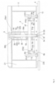
- Figures 1 and 2 show a system 1 having a formwork device 2.
- the formwork device 2 has a formwork section 21 for shaping concrete parts and is coupled to a magnetic device 3.
- the magnetic device 3 comprises two magnet packages 31a and 31b, each of which can be transferred between an interaction position and a release position.
- Figures 1 and 2 show the magnet packages 31a and 31b in the interaction position in which the magnet packages 31a and 31b are in a magnetic operative connection with a magnetizable formwork base 4.
- the magnet packages 31a and 31b rest with their underside on the formwork base 4.
- the formwork device 4 is made of a ferromagnetic material and is therefore magnetizable.
- In the interaction position of the two magnet packages 31a and 31b there is a magnetic interaction between the formwork base 4 and the two magnet packages 31a and 31b, which applies a force component to the magnet packages 31a and 31b in the direction of the formwork base 4.
- the two similar magnet packages 31a and 31b each have at least one permanent magnet.
- the magnet packages 31a and 31b each have a plurality of permanent magnet elements in bar form that are spaced parallel to one another, and also ferromagnetic elements arranged between them.
- the magnetic force acting on the magnet packages 31a and 31b is transferred to the formwork device 2, so that the formwork device 2 is fixed in its position.
- the formwork section 21 forms a lateral boundary for a concrete part to be poured.
- the formwork device can withstand high concreting pressures and enable concrete parts to be manufactured to exact dimensions.
- the magnet device 3 has a single pivot axis 32, around which the two magnet packages 31a and 31b are each pivotably mounted.
- the magnet packages 31a and 31b are mounted on a Support device 33 is attached.
- the support device has a block-shaped part through which a cylindrical shaft 34 extends parallel to the formwork support 4, penetrating parallel opposite side surfaces, so that cylindrical projections protrude from the two side surfaces.
- a central axis of the shaft 34 forms the pivot axis 32.
- the support device 33 further comprises an axially symmetrical opening 35 extending from an upper side of the block-shaped part downwards in a direction perpendicular to the formwork base 4.
- a cylindrical bolt 36 is arranged in the opening 35 so as to be relatively movable relative to the support device 33.
- the bolt 36 extends linearly in a direction perpendicular to the formwork support 4.
- the bolt 36 has a first threaded section 36a and a second threaded section 36b.
- a lever plate 37 is arranged which extends essentially perpendicularly to both sides of the bolt 36 parallel to the formwork support 4.
- the lifting plate 37 arranges the bolt centrally inside a through opening.
- the lever plate 37 has a substantially cuboidal rod shape.
- the lever plate 37 is secured to the bolts 36 above and below via lock nut structures 5a and 5b. This allows for simple production while simultaneously ensuring secure force transmission.
- the lever plate 37 preferably has an internal thread in the area of the through hole. This makes the force transmission more efficient.
- the lever plate 37 has elongated holes 37b1 and 37b2 penetrating the lever plate 37.
- the elongated holes 37b1 and 37b2 are each penetrated by bolts 6a and 6b in a direction perpendicular to the direction of extension of the lever plate 37.
- Plate-shaped compensation elements 7a and 7b are rotatably mounted on the bolts 6a and 6b.
- the plate-shaped compensation elements 7a and 7b are penetrated at one end on the side of the lever plate 37 by the bolts 6a and 6b. At the opposite end, the plate-shaped compensation elements 7a and 7b each have openings through which the bolts 8a and 8b are guided.
- the magnet packages 31a and 31b are each rotatably mounted on these bolts 8a and 8b.
- the lever plate 37 has cylindrical openings 37c1 and 37c2 on both sides of the bolt 36, which penetrate the lifting plate 37 in the linear direction of movement.
- the openings 37c1 and 37c2 are each penetrated by guide rods 11a and 11b, which are provided on the formwork device 2.
- a button 9 as an actuating element is screwed via an internal thread to the second threaded portion 36b at an upper end of the bolt 36.
- the button 9 extends in the linear movement direction.
- the button 9 On its underside, the button 9 has a recessed receiving space 9a which extends upwards and is delimited by a bottom surface 9b.
- the formwork device 2 has a bushing 22.
- the bushing 22 can be provided on the formwork device 2, for example by welding.
- the bushing 22 has a cylindrical recess 22a, which is delimited on an underside by a bottom surface 22b.
- the button 9 rests with the bottom surface 9b on one end of a spring 10, which is partially accommodated in the receiving space 9a.
- the opposite end of the spring 10 rests on the bottom surface 22b of the bushing 22.
- An operator can cause the magnet packages 31a and 31b to perform a pivoting movement about the common pivot axis 32 by pulling on the knob 9 from the interaction position.
- the operator can initiate the pivoting movement of the magnet packages 31a and 31b solely by applying a lifting force in a direction perpendicular to the formwork support 4, i.e. along the linear direction of movement.
- the force is transferred from the button 9 to the central bolt 36 via the second threaded section 36b.
- the force is finally transferred from the central bolt 36 to the outside via the lever plate 37 via the first threaded section 36a and the lock nut structures 5a and 5b, where it is introduced into the magnet packages 31a and 31b via the bolts 6a and 6b, the compensation elements 7a and 7b and the bolts 8a and 8b.
- the bolts 8a and 8b are therefore each load introduction points for the magnet packages 31a and 31b, while the bolts 6a and 6b are each coupling points of the lever plate 37 as part of the actuating device with the magnet packages 31a and 31b.
- the lifting force is introduced into the magnet packages 31a and 31b as a force pointing essentially in a direction perpendicular to the formwork base 4.
- the lifting forces distributed between the two bolts 8a and 8b each act with a lever arm 12a or 12b with respect to the pivot axis 32.
- a torque acts on the magnet packages 31a and 31b, which is not absorbed by the shaft 34 of the support device 33. Therefore, the magnet packages 31a and 31b each perform a pivoting movement, while the actuating device, which is formed by the button 9, the bolt 36 and the lever plate 37, is moved linearly perpendicularly away from the formwork base 4.
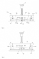
- a switchable magnet device 3 which comprises a plurality of magnet packages 31a, 31b, which can be transferred between an interaction position in which the magnet package 31a or 31b with a formwork base 4 is in a magnetic operative connection with the formwork base, and a release position in which the magnetic operative connection between the formwork base and the magnet packages is reduced.
- the release position is in Fig. 4 shown.
- the magnet packages are shown in a pivoted position.
- the magnet device 3 is thus configured such that the plurality of magnet packages 31a, 31b performs a pivoting movement about the pivot axis 32 at least in sections during the transfer between the interaction position and the release position.
- the magnetic device comprises an actuating device 9, 36 and 37 which can be coupled to the plurality of magnet packages 31a, 31b for transferring the plurality of magnet packages 31a, 31b between the interaction position and the release position.
- the magnetic device is configured such that the actuating device 9, 36 and 37 carries out a linear movement along a linear movement direction at least temporarily during the pivoting movement of the plurality of magnet packages 31a, 31b.
- the plurality of magnet packages 31a, 31b performs a pivoting movement about the pivot axis 32 at least in sections during the transfer between the interaction position and the release position.
- the lifting force transmitted to the magnet packages via the actuating device 9, 36 and 37 can be reduced by lever arm action.
- the magnet device 3 is configured such that the actuating device 9, 36 and 37 at least temporarily during the pivoting movement of the plurality of magnet packages 31a, 31b performs a linear movement along a linear movement direction. Therefore, work can be carried out in a small work space and the operation is made easier for an operator. In particular, the Operator pulls the button 9 along the linear direction of movement.
- the actuating device 9, 36 and 37 does not have to be supported on a swivel axis of a formwork device for transfer. This makes configuration easier.
- the magnetic device 3 comprises a plurality of magnet packages 31a and 31b.
- the magnetic device is configured such that the plurality of magnet packages 31a and 31b at least temporarily simultaneously perform the pivoting movement about their respective pivot axis 32.
- the plurality of magnet packages 31a and 31b each perform a pivoting movement about their respective pivot axis 32, which enables easy lifting. Since the pivoting movement can take place at least temporarily simultaneously, the magnet packages can be lifted off evenly, as shown in Fig. 4 is shown.
- the linear movement direction is a direction substantially perpendicular to the formwork base.
- the actuating device is coupled to the magnet packages 31a and 31b via the compensation elements 7a and 7b.
- the compensation elements 7a and 7b can each be rotated about the bolts 6a and 6b.
- the magnet packages 31a and 31b can each be rotated with respect to the compensation elements 7a and 7b by the bolts 8a and 8b.
- the magnet packages 31a and 31b therefore each have two rotational degrees of freedom connected in series about axes that are parallel to the pivot axis 32 but spaced apart from one another with respect to the actuating device.
- the magnet packages therefore each have at least one degree of freedom that intersects the linear direction of movement with respect to the section of the actuating device that can be moved linearly along the linear direction of movement (here the rigid body formed by bolt 36, lever plate 37 and button 9).
- the guide rods 11a and 11b are provided, which penetrate the openings 37c1 and 37c2, respectively.
- a pair of guide rods 11a and 11b and borders of the openings 37c1 and 37c2 constitute a guide device.
- the actuating device moves linearly upwards and is guided by the guide rods 11a and 11b.
- the lifting plate 37 is in Fig. 4 arranged higher than in Fig. 3 .
- the central bolt 36 is also provided to slide in the opening 35 of the support device.
- the edge of the opening 35 and the bolt 36 also form a guide device.
- the bolt 36 is in Fig. 4 further from the support device 33 than in Fig. 3 .
- an outer peripheral surface 9c of the button 9 is slidably received in the recess 22a of the bushing 22. Therefore, the edge of the recess 22a together with the button also represents a guide device.
- each of the sections 9, 36, 37 is guided along the linear direction of movement. This allows the linear movement of the actuating device to be reliably achieved. Potential constraining forces can also be absorbed by the guide device, which can prevent the magnet package and actuating device from jamming.
- the bolts 8a and 8b are load introduction points for the magnet packages 31a and 31b.
- the bolts are each attached to an end of the magnet packages 31a and 31b that is remote from the pivot axis 32 in a direction perpendicular to the pivot axis 32.
- the resulting magnetic forces Fmag acting on the magnet packages 31a and 31b can be regarded as acting in the center of the magnet packages 31a and 31b.
- the actuating device for carrying out the pivoting movement is coupled to the magnet packages 31a and 31b at a load introduction point which is further away from the respective pivot axis 32 than the point of application of the resulting force Fmag which acts on the plurality of magnet packages through the magnetic active connection.
- the magnet device 3 has a support device 33 on which the magnet packages 31a and 31b are pivotably mounted about the respective pivot axis 32.
- the pivot axis 32 can be specified by the support device 33.
- the magnet packages can therefore have a well-defined pivot axis 32 on the magnet device 3 and do not have to be mounted on the formwork base, for example.
- the support device can also take on other tasks such as guiding the central bolt 36, as described above.
- the central bolt 36 as part of the actuating device is provided in a sliding manner in the opening 35 of the support device 33.
- the one actuating device is relatively movable with respect to the at least one support device along the linear direction of movement.
- the pivoting movement can be reliably introduced into the magnet packages 31a and 31b, since the relative movement between the support device and the actuating device ensures freedom of movement for the pivoted magnet packages.
- the magnet packages 31a and 31b are not only pivoted in the release position, but are also lifted off the formwork base 4 together with the support device 33 in a direction perpendicular to the formwork base 4.
- the support device 33 which supports the magnet packages on the shaft 34, can be lifted off the ground.
- the magnet device 3 is thus configured such that the magnet packages perform a translational movement during or after the pivoting movement about the respective pivot axis 32.
- the swivel movement allows the magnetic force resulting from the magnetic interaction between the large number of magnet packages and the formwork base to be quickly reduced. With a lower effective magnetic force, the large number of magnet packages can be quickly lifted off the formwork base in a translational manner with a low lifting force.
- the movement of the compensation elements 7a and 7b is limited by the border of the respective elongated holes 37b1 and 37b2.
- the borders of the respective elongated holes 37b1 and 37b2 not only block the movement of the Compensating elements 7a and 7b, but also the pivoting movement of the magnet packages.
- the locking mechanism is also configured by the borders of the respective elongated holes 37b1 and 37b2 in such a way that it blocks the relative movement between the actuating device and the at least one support device 33.
- the pivoting movement can be blocked after a predetermined path along the pivoting movement, which makes the necessary working space for a continuous pivoting movement superfluous.
- the magnetic force is reduced after a predetermined path along the pivoting movement, which allows a slight translational lifting to take place. If the pivoting movement is blocked, a lifting force with a component along the linear direction of movement can reliably initiate a translational movement of the plurality of magnet packages. Since the actuating device is relatively movable with respect to the at least one support device, the pivoting movement can be reliably blocked by blocking this degree of freedom.
- the bolts 6a and 6b act as coupling points of the actuating device with the magnet packages.
- the bolts 6a and 6b are arranged symmetrically with respect to a central axis of the central bolt 36 on both sides.
- the central axis of the bolt 36 runs along the linear direction of movement and also runs through an actuating point at which a load (the lifting force) is introduced into the actuating device.
- the actuating point here is the button 9, more precisely its central axis, which coincides with the central axis of the bolt 36 when assembled.
- a resulting lifting force that an operator introduces into the actuating device is usually introduced along the central axis.
- the coupling points are arranged symmetrically with respect to the axis of the resulting lifting force (central axis of the bolt 36) and thus have a lever arm of the same size to this axis, and in the case of locked compensation elements, the moments are opposite to each other, no resulting moment acts on the actuating device (on the section that can move linearly along the linear direction of movement) when it is subjected to the lifting force. If no torque acts on the actuating device, the actuating device can be moved particularly easily along the linear direction of movement. In particular, no constraining forces arise. This can be achieved in particular by arranging the coupling points symmetrically with respect to an axis that runs along the linear direction of movement through an actuating point at which an operator grips the actuating device.
- the coupling points for carrying out the pivoting movement can be arranged in such a way that no torque acts on the actuating device.
- the actuating device can thus be moved particularly easily along the linear direction of movement even during the pivoting movement of the magnet packages. In particular, no constraining forces arise. This can be achieved in particular by arranging the coupling points symmetrically with respect to an axis that runs along the linear direction of movement through an actuating point at which an operator grips the actuating device.
- the actuating device has the bolt 36 and the button 9, both of which extend coaxially along the linear direction of movement.
- Bolt 36 and button 9 thus represent a linear extension section whose axis extends along the linear direction of movement.
- a lifting force can be transmitted along the linear direction of movement along the linear extension section.
- the actuating device has the lever plate 37, which shifts forces away from the axis of the linear extension section (axis of the bolt 36 and the button 9).
- the lifting plate is a lever section that is configured to shift a force with a component along the linear movement direction from an axis of the linear movement direction, which runs along the linear movement direction through an actuating point at which a load is introduced into the actuating device, to at least one coupling point away from the axis of the linear movement direction.
- the lever section is force-lockingly coupled to the linear extension section via the two lock nut structures 5a and 5b.
- the lever section allows the actuation point to be provided at a distance from the coupling points at which the actuation device is coupled to the plurality of magnet packages. This allows adaptation to spatial boundary conditions in a formwork device.
- a lifting force can be introduced centrally into the lever section and then shifted outwards for introduction into the magnet packages in order to ensure the largest possible lever arm.
- a single actuating device 9, 36 and 37 is further coupled to the magnet packages 31a and 31b.
- the magnet packages 31a and 31b are also arranged at circumferential angles of 180° from one another. More precisely, the perpendiculars to the pivot axis 32 of the two magnet packages 31a, which run parallel to the formwork base 4, form a straight line. The magnet packages 31a and 31b are thus arranged evenly in a circumferential direction around a central axis.
- the center axis of the bolt 36 coincides with the center axis around which the magnet packs 31a and 31b are evenly arranged.
- the center axis around which the magnet packs 31a and 31b are evenly arranged coincides with an axis of the linear movement direction that runs along the linear movement direction through an actuation point at which a load is introduced into the actuation device.
- the lifting force can be introduced centrally and then distributed evenly to the magnet packages around the central axis.
- a single support device 33 is arranged in a middle between the plurality of magnet packages.
- the central axis of the bolt 36 runs through the support device 33 and is also a central axis of the support device 33.
- the magnet packages 31a and 31b, which are opposite one another, have a common pivot axis.
- the support device 33 can be arranged centrally and a symmetrical introduction of force into the support device 33 can be achieved.
- the system has a formwork device 2, which has a formwork section 21 for shaping concrete parts, and a switchable magnetic device 3 according to the preceding embodiments.
- the switchable magnetic device is coupled to the formwork device 2 at least in the interaction position of the magnet packages 31a and 31b in such a way that a contact force with a component in the direction of the formwork base 4 is transmitted to the formwork device.
- the above magnetic device can fix the formwork device in its position in the interaction position.
- access to the actuating device on the formwork device can be provided in a relatively small manner compared to the prior art, in which a large recess is provided for the actuating lever.
- the formwork device 2 as in Fig. 1 shown, has a formwork support section 23.
- the formwork support section 23 supports the formwork section 21 and has a cover section 23a, which lies on a side facing away from the formwork base 4 and preferably extends horizontally here.
- cover section 23a On both sides in the longitudinal direction of the formwork device 2, which is defined by the longitudinal extent of the formwork section 21, lateral sections 23b extend from the cover section 23a downwards in the direction of the formwork base.
- the cover section 23a and the two lateral sections 23b form a receiving space, in the interior of which the magnetic device is accommodated at least in sections. Only the button 9 protrudes upwards from the formwork support section 23.
- the button 9 is designed to be detachable from the bolt 36 so that the button 9 can also be removed.
- the actuating device thus has a detachable section that can be coupled to actuate the magnetic device.
- the formwork device (the formwork support section 23) comprises the guide bushing 22 which guides the button 9 along the linear movement direction.
- at least one guide device comprises a section of the formwork device.
- the guide bushing can be attached to the formwork device particularly easily, for example by welding.
- the button 9 rests with the bottom surface 9b on one end of a spring 10, which is partially accommodated in the receiving space 9a.
- the spring 10 is designed here as a compression spring.
- the opposite end of the spring 10 rests on the bottom surface 22b of the bushing 22.
- the system 1 thus has at least one elastic element via which the magnetic device 3 is coupled to the formwork device 2 at least in the interaction position of the plurality of magnet packages. More precisely, the spring 10 is arranged between the magnetic device 3 and the formwork device 2.
- the magnetic device has at least one release support device that is configured to support transferring the respective magnet package into the release position.
- the release support device is preferably coupled to the at least one support device and preferably has at least one elastic element, particularly preferably a spring element.
- the spring 10 just described is also part of a release support device. The elastic spring force supports the lifting of the magnet packages and can optionally hold the magnet packages in the release position.
- a substantially rectangular frame plate 13 is used for the assembly.
- the frame plate has a substantially rectangular recess 13a, which has larger dimensions than the assembled magnet packages 31a and 31b.
- the frame plate 13 can rest on a non-magnetic base, for example a wooden table, whereby the base also has a recess at least the size of the recess 13a.
- the magnet packages 31a and 31b pre-assembled on the support device 33 can then be inserted into the recess.
- the actuating device is also pre-assembled except for the button 9.
- the guide rods 11a and 11b are provided on the frame plate 13.
- the pre-assembled actuating device can then simply be placed on the guide rods 11a and 11b via the openings 37c1 and 37c2.
- the pre-assembled magnet packages 31a and 31b can be aligned accordingly and coupled to the actuating device via the compensation elements 7a and 7b.
- the frame plate 13 also has an auxiliary assembly opening 13b on both transverse sides.
- the formwork device 2 also has corresponding auxiliary assembly openings on a lower section 23c, which faces the formwork base 4 and extends parallel to the cover section 23a. It should be noted that the formwork device 2 is rotated for better assembly, as shown in Fig. 5 In particular, the lower section 23c is shown in Fig. 5 directed upwards.
- dowel pins are fitted into the auxiliary assembly openings of the formwork device.
- the auxiliary assembly openings 13b of the frame plate 13 are then aligned and fitted with the dowel pins.
- the frame plate 13 is then attached to the formwork device 2 via through holes 13c at all four corners of the frame plate with corresponding holes in the lower section 23c of the formwork device 2 by means of bolts and nuts which are in Fig. 1 shown. Finally, the dowel pins are pulled out.
- the frame plate 13 When assembled and aligned on the formwork support 4, the frame plate 13 is located below the lower section 23c.
- the frame section 13 is provided, which has at least one guide device 11a or 11b and at least one positioning aid 13b.
- the magnet packages can thus be aligned according to the guide section and coupled to the actuating device coupled to the guide device.
- the entire pre-assembled magnet device 3 can then be aligned relative to the formwork device using the positioning aid.
- the magnet device can thus be constructed separately from the formwork device.
- the assembly is further facilitated if the support device as well as the actuating device and the articulated connection via the bolts 6a and 6b as well as 8a and 8b and compensating elements 7a and 7b are made of non-magnetic materials.
- these parts can be made of non-magnetic metals or synthetic resins.
- the magnet packages are pivoted and moved translationally.
- the release position can also be a position in which the multitude of magnet packages are merely pivoted.
- the sequence of translation and pivoting movement is also not fixed.
- the multitude of magnet packages can first be pivoted into an intermediate pivoting position, from which they are then only lifted translationally into the complete release position. Translation and pivoting movement can also be carried out simultaneously.
- the form of the locking mechanism is also not limited.
- the pivoting movement can also be blocked by a stop in the support device 33, against which a projection at the lower end of the bolt 36 rests.
- the relative movement of the parts that are relatively movable to one another, the support device 33 and the actuating device (bolt 36 thereof), is immediately blocked.
- the number of guide devices is not specified. However, one guide device is preferably provided for each coupling point.
- the degree of freedom intersecting the linear direction of movement is not limited to a rotational degree of freedom.
- At least one translational degree of freedom intersecting the linear direction of movement can also be provided with respect to the linearly moving section (rigid section made up of button 9, bolt 36 and lever plate 37, which form a rigid body in the above embodiment).
- a sliding block can also be provided which can move in a direction intersecting the linear direction of movement, preferably perpendicular to the linear direction of movement, in the above embodiment thus parallel to the formwork base, in which the plurality of magnet packages can move in a sliding manner.
- the sliding block is preferably also mounted in an articulated manner in order to allow compensation in the orientation.
- An elastic Element such as an elastomer section, may be provided between or within the actuator and magnet package.
- the actuating device can also be designed integrally.
- the actuating device can comprise one or more sections that are positioned upstream of the force flow when transferring a lifting force to the plurality of magnet packages.
- the form of the release support device is also not limited.
- an elastic element such as a compression spring can be provided on the side of the formwork base, which is arranged between the support device and the formwork base.
- the spring force can support a movement away from the formwork base. In particular, a translational movement can be supported.
Landscapes
- Engineering & Computer Science (AREA)
- Manufacturing & Machinery (AREA)
- Chemical & Material Sciences (AREA)
- Ceramic Engineering (AREA)
- Mechanical Engineering (AREA)
- Physics & Mathematics (AREA)
- Electromagnetism (AREA)
- Power Engineering (AREA)
- Moulds, Cores, Or Mandrels (AREA)
- Looms (AREA)
- Forms Removed On Construction Sites Or Auxiliary Members Thereof (AREA)
- Sewing Machines And Sewing (AREA)
Description
- Die vorliegende Erfindung betrifft eine schaltbare Magnetvorrichtung sowie ein System, umfassend eine Schalungsvorrichtung und eine schaltbare Magnetvorrichtung.
- Aus der Gebrauchsmusterschrift
DE 203 09 970 U1 ist eine schaltbare Magnetvorrichtung eine Magnetvorrichtung zum Fixieren einer Schalungsvorrichtung auf einer Schalungsunterlage bekannt. Ein Magnet ist um eine Schwenkachse schwenkbar gelagert. Der Magnet kann von einer Arretierstellung, in der sich der Magnet mit einer Schalungsunterlage in magnetischer Wirkverbindung befindet, durch einen Betätigungshebel, der mit dem Magneten gekoppelt wird, in eine Lösestellung überführt werden. In der Arretierstellung wird die Schalungsvorrichtung zum Fertigen von Betonteilen in ihrer Position fixiert. - Weiterhin zeigt
SU 1 527 123 A2 US 6 168 221 B1 offenbart eine schaltbare Magnetvorrichtung, bei der zwei Magnetpakete gleichzeitig um eine Schwenkachse durch eine lineare Betätigung bewegt werden. - Durch den Hebelarm von der Schwenkachse bis zum Angriffspunkt des Hebels wird die Abhebekraft, um den Magneten von der Schalungsunterlage zu lösen, reduziert gegenüber dem Fall, in dem der Magnet translatorisch abgehoben wird.
- Allerdings muss zum Betätigen des Magneten der Betätigungshebel selbst geschwenkt werden, was einen erheblichen Arbeitsraum erfordert. Weiterhin stützt sich der Betätigungshebel während der Schwenkbewegung an einer Schalungsvorrichtung ab, was zu einer erheblichen Beanspruchung der Schalungsvorrichtung führt. Deshalb müssen diese Schalungsvorrichtungen entsprechend dimensioniert werden. Auch können an der Kopplungsstelle zwischen Betätigungshebel und Magnet Reibungskräfte oder gar Verklemmen auftreten, was die tatsächlichen Abhebekräfte erhöht.
- Die vorliegende Erfindung wurde in Anbetracht der zuvor erwähnten Probleme gemacht und ihr liegt die Aufgabe zu Grunde, eine schaltbare Magnetvorrichtung vorzusehen, die einen geringen Arbeitsraum erfordert und ein leichtes Abheben des Magneten von der Schalungsunterlage erlaubt.
- Diese Aufgabe wird durch eine schaltbare Magnetvorrichtung gemäß Anspruch 1 gelöst. Bevorzugte Ausführungsformen sind in den Unteransprüchen dargelegt.
- Gemäß einem ersten Aspekt wird eine schaltbare Magnetvorrichtung vorgesehen, die eine Vielzahl von Magnetpaketen umfasst, das zwischen einer Interaktionsstellung, in der sich das Magnetpaket bevorzugt mit einer magnetisierbaren Schalungsunterlage vorzugsweise durch Anlage an die Schalungsunterlage in einer magnetischen Wirkverbindung mit der Schalungsunterlage befindet, und einer Lösestellung überführbar ist, in der die magnetische Wirkverbindung zwischen der Schalungsunterlage und dem Magnetpaket reduziert ist, vorzugsweise aufgehoben ist. Die Magnetvorrichtung ist so konfiguriert, dass Vielzahl von Magnetpaketen während des Überführens zwischen der Interaktionsstellung und der Lösestellung zumindest abschnittsweise eine Schwenkbewegung um eine Schwenkachse durchführt. Weiterhin umfasst die Magnetvorrichtung eine Betätigungseinrichtung, die zum Überführen der Vielzahl von Magnetpaketen zwischen der Interaktionsstellung und der Lösestellung mit der Vielzahl von Magnetpaketen koppelbar ist. Die Magnetvorrichtung ist so konfiguriert, dass Betätigungseinrichtung zumindest zeitweise während der Schwenkbewegung der Vielzahl von Magnetpaketen eine lineare Bewegung entlang einer linearen Bewegungsrichtung durchführt.
- Gemäß dem obigen Aspekt führt die Vielzahl von Magnetpaketen während des Überführens zwischen der Interaktionsstellung und der Lösestellung zumindest abschnittsweise eine Schwenkbewegung um eine Schwenkachse durch. Dabei kann durch die bereits oben angesprochene Hebelarmwirkung die Abhebekraft, die durch die Betätigungseinrichtung auf die Magnetpakete übertragen wird, reduziert werden. Allerdings ist die Magnetvorrichtung so konfiguriert, dass die Betätigungseinrichtung zumindest zeitweise während der Schwenkbewegung der Vielzahl von Magnetpaketen eine lineare Bewegung entlang einer linearen Bewegungsrichtung durchführt. Deshalb kann in einem kleinen Arbeitsraum gearbeitet werden und die Betätigung wird für einen Bediener erleichtert. Auch muss sich die Betätigungseinrichtung zum Überführen nicht an einer Schwenkachse einer Schalungsvorrichtung abstützen. Das erleichtert die Konfiguration.
- Die Magnetvorrichtung weisen eine Vielzahl der Magnetpakete auf, und ist die Magnetvorrichtung so konfiguriert, dass die Vielzahl von Magnetpaketen zumindest vorübergehend gleichzeitig die Schwenkbewegung um ihre jeweilige Schwenkachse durchführen.
- Da eine Vielzahl von Magnetpaketen vorgesehen wird, können hohe Magnetkräfte erzielt werden, mit denen eine Schalungsvorrichtung gegen die Schalungsunterlage gepresst wird. Die Vielzahl von Magnetpaketen führen jeweils eine Schwenkbewegung um ihre jeweilige Schwenkachse durch, was ein leichtes Abheben ermöglicht. Da die Schwenkbewegung zumindest vorübergehend gleichzeitig vonstattengehen kann, kann ein gleichmäßiges Abheben der Magnetpakete erfolgen.
- Vorzugsweise ist die lineare Bewegungsrichtung eine zur Schalungsunterlage im Wesentlichen senkrechte Richtung.
- Dadurch kann das Abheben der Magnetpakete besonders schnell und effektiv erfolgen. Auch kann ein Arbeitsraum klein in einer Richtung parallel zur Schalungsunterlage gehalten werden.
- Gemäß einem weiteren Aspekt kann die Betätigungseinrichtung mit der Vielzahl von Magnetpaketen so gekoppelt sein, dass die Vielzahl von Magnetpaketen bezüglich des sich entlang der linearen Bewegungsrichtung linear bewegbaren Abschnitts der Betätigungseinrichtung jeweils zumindest einen die lineare Bewegungsrichtung schneidenden Freiheitsgrad aufweist.
- Dadurch kann auf besonders einfache Weise eine Entkopplung der Schwenkbewegung der Vielzahl von Magnetpaketen und der Linearbewegung zumindest eines Abschnitts der Betätigungseinrichtung erzeugt werden. Vorzugsweise ist zumindest ein Freiheitsgrad ein rotatorischer Freiheitsgrad um eine zur Schwenkachse parallele Achse. Dadurch kann ein Verklemmen von Magnetpaketen und Betätigungseinrichtung effektiv verhindert werden. Vorzugsweise weist die Magnetvorrichtung zumindest eine Führungseinrichtung auf, die konfiguriert ist, die Betätigungseinrichtung entlang der linearen Bewegungsrichtung zu führen.
- Dadurch kann die lineare Bewegung der Betätigungseinrichtung zuverlässig erzielt werden. Auch können potentielle Zwangskräfte durch die Führungseinrichtung aufgenommen werden, was ebenfalls ein Verklemmen von Magnetpaketen und Betätigungseinrichtung verhindern kann. Die Betätigungseinrichtung zum Durchführen der Schwenkbewegung ist mit der Vielzahl von Magnetpaketen jeweils an einer Lasteinleitungsstelle gekoppelt, die von der jeweiligen Schwenkachse weiter entfernt ist als die Angriffsstelle der resultierenden Kraft, die durch die magnetische Wirkverbindung jeweils auf die Vielzahl von Magnetpaketen wirkt.
- Damit kann zuverlässig sichergestellt werden, dass eine geringere Abhebekraft als die resultierende magnetische Kraft zum Abheben der Magnetpakete benötigt wird.
- Die Magnetvorrichtung weist zumindest eine Stützeinrichtung auf, an der die Vielzahl von Magnetpaketen um die jeweilige Schwenkachse schwenkbar gelagert ist. Durch die Stützeinrichtung wird eine Schwenkachse vorgegeben. Somit können die Magnetpakete eine wohl definierte Schwenkachse an der Magnetvorrichtung aufweisen und müssen beispielsweise nicht an der Schalungsunterlage gelagert werden.
- Die Betätigungseinrichtung ist bezüglich der zumindest einen Stützeinrichtung, besonders bevorzugt, entlang der linearen Bewegungsrichtung, relativ beweglich.
- Dadurch kann die Schwenkbewegung zuverlässig in die Magnetpakete eingeleitet werden, da durch die Relativbewegung zwischen Stützeinrichtung und Betätigungseinrichtung eine translatorische Bewegung der Vielzahl von Magnetpaketen unterbunden werden kann.
- Gemäß noch einem weiteren Aspekt kann die Magnetvorrichtung so konfiguriert sein, dass die Vielzahl von Magnetpaketen während oder nach der Schwenkbewegung um die jeweilige Schwenkachse eine Translationsbewegung durchführt.
- Durch die Schwingbewegung kann die magnetische Kraft, die aus der magnetischen Wechselwirkung zwischen der Vielzahl von Magnetpaketen und der Schalungsunterlage resultiert, schnell reduziert werden. Bei geringerer wirkender Magnetkraft kann die Vielzahl von Magnetpaketen mit einer geringen Abhebekraft schnell translatorisch von der Schalungsunterlage abgehoben werden.
- Vorzugsweise weist die Magnetvorrichtung weiterhin einen Sperrmechanismus auf, der konfiguriert ist, die Schwenkbewegung der Vielzahl von Magnetpaketen zu sperren. Besonders bevorzugt ist der Sperrmechanismus so konfiguriert, dass er die relative Bewegung zwischen der Betätigungseinrichtung und der zumindest einen Stützeinrichtung sperrt Dadurch kann nach einem vorbestimmten Pfad entlang der Schwenkbewegung die Schwenkbewegung gesperrt werden, was einen nötigen Arbeitsraum für eine fortlaufende Schwenkbewegung überflüssig macht. Wie oben bereits dargelegt, ist die Magnetkraft nach einem vorbestimmten Pfad entlang der Schwenkbewegung herabgesetzt, wodurch ein leichtes translatorisches Abheben erfolgen kann. Ist die Schwenkbewegung gesperrt, kann eine Abhebekraft mit einer Komponente entlang der linearen Bewegungsrichtung zuverlässig eine translatorische Bewegung der Vielzahl von Magnetpaketen in Gang setzen. Da die Betätigungseinrichtung bezüglich der zumindest einen Stützeinrichtung relativ beweglich ist, kann durch das Sperren dieses Freiheitsgrades die Schwenkbewegung zuverlässig gesperrt werden.
- Gemäß einem weiteren Aspekt kann die Betätigungseinrichtung zumindest während der Translationsbewegung der Vielzahl von Magnetpaketen Kopplungsstellen mit der Vielzahl von Magnetpaketen aufweisen, die so angeordnet sind, dass kein Drehmoment auf die Betätigungseinrichtung wirkt. Vorzugsweise sind die Kopplungsstellen symmetrisch bezüglich einer Achse der linearen Bewegungsrichtung angeordnet, die durch eine Betätigungsstelle, an der eine Last in die Betätigungseinrichtung eingeleitet wird, entlang der linearen Bewegungsrichtung verläuft.
- Wirkt kein Drehmoment auf die Betätigungseinrichtung, so kann die Betätigungseinrichtung besonders einfach entlang der linearen Bewegungsrichtung bewegt werden. Insbesondere entstehen keine Zwangskräfte. Dies kann insbesondere dadurch erreicht werden, dass die Kopplungsstellen bezüglich einer Achse, die durch eine Betätigungsstelle, an der ein Bediener die Betätigungseinrichtung greift, entlang der linearen Bewegungsrichtung verläuft, symmetrisch angeordnet sind.
- Vorzugsweise weist die Betätigungseinrichtung einen linearen Erstreckungsabschnitt auf, der sich entlang der linearen Bewegungsrichtung erstreckt.
- Das erleichtert die Ausrichtung entlang der linearen Bewegungsrichtung und damit die Bedienbarkeit für einen Bediener. Zusätzlich kann eine Abhebekraft entlang der linearen Bewegungsrichtung entlang des linearen Erstreckungsabschnitts übertragen werden.
- Gemäß noch einem weiteren Aspekt kann die Betätigungseinrichtung zumindest einen Hebelabschnitt aufweisen, der konfiguriert ist, eine Kraft mit einer Komponente entlang der linearen Bewegungsrichtung von einer Achse der linearen Bewegungsrichtung, die durch eine Betätigungsstelle, an der eine Last in die Betätigungseinrichtung eingeleitet wird, entlang der linearen Bewegungsrichtung verläuft, jeweils an zumindest eine Kopplungsstelle entfernt von der Achse der linearen Bewegungsrichtung zu verlagern. Vorzugsweise ist der Hebelabschnitt mit dem zuvor erwähnten linearen Erstreckungsabschnitt gekoppelt.
- Durch den Hebelabschnitt kann die Betätigungsstelle beabstandet von den Kopplungsstellen, an denen die Betätigungseinrichtung mit dem zumindest ein Mangelpaket gekoppelt ist, vorgesehen werden. Somit kann eine Anpassung an räumliche Randbedingungen in einer Schalungsvorrichtung erfolgen. Außerdem kann eine Abhebekraft zentral in den Hebelabschnitt eingeleitet werden und dann nach außen zum Einleiten in die Magnetpakete verlagert werden, um einen möglichst großen Hebelarm zu gewährleisten.
- Eine einzige Betätigungseinrichtung ist mit der Vielzahl von Magnetpaketen koppelbar.
- Das vereinfacht die Konfiguration, da ein Bediener die Vielzahl von Magnetpaketen über eine einzige Betätigungseinrichtung von der Arretierstellung in die Lösestellung überführen kann. Vorzugsweise weist die eine Betätigungseinrichtung zum Durchführen der Schwenkbewegung der Vielzahl von Magnetpaketen Kopplungsstellen mit den Magnetpaketen auf, die so angeordnet sind, dass kein Drehmoment auf die Betätigungseinrichtung wirkt. Die Kopplungsstellen sind bevorzugt symmetrisch bezüglich einer Achse der linearen Bewegungsrichtung angeordnet, die durch eine Betätigungsstelle, an der eine Last in die Betätigungseinrichtung eingeleitet wird, entlang der linearen Bewegungsrichtung verläuft.
- Die Kopplungsstellen auch zum Durchführen der Schwenkbewegung können so angeordnet sein, dass kein Drehmoment auf die Betätigungseinrichtung wirkt. So kann die Betätigungseinrichtung besonders einfach entlang der linearen Bewegungsrichtung auch während der Schwenkbewegung der Magnetpakete bewegt werden. Insbesondere entstehen keine Zwangskräfte. Dies kann insbesondere dadurch erreicht werden, dass die Kopplungsstellen bezüglich einer Achse, die durch eine Betätigungsstelle, an der ein Bediener die Betätigungseinrichtung greift, entlang der linearen Bewegungsrichtung verläuft, symmetrisch angeordnet sind.
- Vorzugsweise ist zumindest ein Teil der Vielzahl von Magnetpaketen gleichartig ausgebildet. Somit können jeweils gleich große Magnetkräfte zwischen den einzelnen Magnetpaketen und der Schalungsunterlage wirken. Damit kann eine gleichmäßige Belastung der Betätigungseinrichtung ermöglicht werden, die insbesondere im Ausbleiben eines Drehmoments für die Betätigungseinrichtung resultiert.
- Vorzugsweise sind die Vielzahl von Magnetpaketen gleichmäßig in einer Umfangsrichtung um eine Mittelachse angeordnet.
- Das vereinfacht die Konfiguration und kann ebenfalls für eine gleichmäßige Belastung der Betätigungseinrichtung sorgen.
- Vorzugsweise stimmt die Mittelachse mit einer Achse der linearen Bewegungsrichtung, die durch eine Betätigungsstelle, an der eine Last in die Betätigungseinrichtung eingeleitet wird, entlang der linearen Bewegungsrichtung verläuft, überein.
- Auch das vereinfacht die Konfiguration. Insbesondere kann die Abhebekraft zentral eingeleitet werden und dann gleichmäßig auf die Magnetpakete um die Mittelachse verteilt werden.
- Eine einzige Stützeinrichtung ist in einer Mitte zwischen der Vielzahl von Magnetpaketen angeordnet. Vorzugsweise verläuft die zuvor erwähnte Mittelachse durch die Stützeinrichtung. Alle Magnetpakete von der Vielzahl von Magnetpaketen sind schwenkbar an der einen Stützeinrichtung gelagert. Dabei ist es insbesondere nochmals bevorzugt, wenn einander gegenüberliegende Magnetpakete eine gemeinsame Schwenkachse aufweisen.
- Dadurch wird die Magnetvorrichtung kompakt gehalten und der Arbeitsraum kann klein gehalten werden. Insbesondere kann die Stützeinrichtung zentral angeordnet werden und eine symmetrische Krafteinleitung in die Stützeinrichtung erreicht werden.
- Gemäß einem weiteren Aspekt kann die Magnetvorrichtung zumindest eine Löseunterstützungseinrichtung aufweisen, die konfiguriert ist, ein Überführen des jeweiligen Magnetpakets in die Lösestellung zu unterstützen. Vorzugsweise ist die Löseunterstützungseinrichtung mit der zumindest einen Stützeinrichtung gekoppelt und weist vorzugsweise zumindest ein elastisches Element, besonders bevorzugt ein Federelement auf.
- Somit kann die von einem Bediener aufzubringende Abhebekraft weiter reduziert werden. So kann auf Seite der Schalungsunterlage beispielsweise ein elastisches Element wie eine Druckfeder vorgesehen sein, die zwischen Stützeinrichtung und Schalungsunterlage angeordnet ist. Die Federkraft kann dabei eine Bewegung weg von der Schalungsunterlage unterstützen.
- Ein weiterer Aspekt ist auf ein System gerichtet, das eine Schalungsvorrichtung, die einen Schalungsabschnitt zur Formgebung von Betonteilen aufweist, und eine schaltbare Magnetvorrichtung gemäß einem der vorangehenden Aspekte aufweist. Die schaltbare Magnetvorrichtung kann zumindest in der Interaktionsstellung der Vielzahl von Magnetpaketen so an die Schalungsvorrichtung gekoppelt sein, dass eine Anpresskraft mit einer Komponente in Richtung der Schalungsunterlage auf die Schalungsvorrichtung übertragen wird.
- Somit kann obige Magnetvorrichtung die Schalungsvorrichtung in der Interaktionsstellung in ihrer Position fixieren. Insbesondere kann ein Zugang zu der Betätigungseinrichtung an der Schalungsvorrichtung verhältnismäßig klein vorgesehen werden gegenüber dem Stand der Technik, in dem eine große Aussparung für den Betätigungshebel vorgesehen ist.
- Vorzugsweise ist die Magnetvorrichtung zumindest abschnittsweise in einem Inneren der Schalungsvorrichtung angeordnet.
- Dadurch kann die Magnetvorrichtung von der Schalungsvorrichtung geschützt werden, und das System kann kompakt ausgeführt werden. Da sich die Betätigungseinrichtung linear bewegen kann, braucht nur eine schmale Aussparung zum Herausführen der Betätigungseinrichtung vorgesehen werden.
- Gemäß einem weiteren Aspekt kann die zumindest eine Führungseinrichtung einen Abschnitt der Schalungsvorrichtung aufweisen, wobei die Schalungsvorrichtung vorzugsweise eine Führungsbuchse aufweist, die konfiguriert ist, einen Abschnitt der Betätigungseinrichtung zu führen. Somit kann die Betätigungseinrichtung von der Schalungsvorrichtung geführt werden, die stabil auf der Schalungsunterlage steht. Damit kann eine stabile Führung sichergestellt werden. Eine Führungsbuchse lässt sich besonders einfach an der Schalungsvorrichtung anbringen.
- Gemäß einem weiteren Aspekt kann das System zumindest ein elastisches Element aufweisen, vorzugsweise ein Federelement aufweisen, über das die Magnetvorrichtung zumindest in der Interaktionsstellung der Vielzahl von Magnetpaketen an die Schalungsvorrichtung gekoppelt ist.
- Dadurch kann sichergestellt werden, dass die Anpresskraft zuverlässig in die Schalungsvorrichtung eingeleitet wird. Insbesondere kann eine Doppelpassung vermieden werden. Weiterhin kann das elastische Element auch als Teil der Löseunterstützungseinrichtung fungieren.
- Die zuvor dargelegten Aspekte werden im Folgenden unter Bezugnahme auf die beigefügten Zeichnungen im Einzelnen erläutert.
-
Fig. 1 zeigt eine perspektivische Ansicht eines Systems, das eine Schalungsvorrichtung und eine Magnetvorrichtung aufweist, wobei die Schalungsvorrichtung auf einer Schalungsunterlage angeordnet ist. -
Fig. 2 zeigt eine Längsschnittansicht des Systems ausFig. 1 , wobei durch eine Längssymmetrieebene der Magnetvorrichtung geschnitten wurde. -
Fig. 3 zeigt eine Seitenansicht der Magnetvorrichtung, wobei die Magnetpakete in einer abgesenkten Stellung (Arretierstellung) dargestellt sind. -
Fig. 4 zeigt eine Seitenansicht der Magnetvorrichtung, wobei die Magnetpakete in einer angehobenen Stellung (Lösestellung) dargestellt sind. -
Fig. 5 eine Schalungsvorrichtung mit einer Magnetvorrichtung während der Montage in perspektivischer Ansicht. - In der folgenden Beschreibung sind Richtungsangaben wie beispielsweise "oben" und "unten" nicht einschränkend zu verstehen. Vielmehr sollen sie nur das Verständnis der Anordnungen erleichtern.
-
Figuren 1 und2 zeigen ein System 1, das eine Schalungsvorrichtung 2 aufweist. Die Schalungsvorrichtung 2 weist einen Schalungsabschnitt 21 zur Formgebung von Betonteilen auf und ist mit einer Magnetvorrichtung 3 gekoppelt. - In der vorliegenden Ausführungsform umfasst die Magnetvorrichtung 3 zwei Magnetpakete 31a und 31b, die jeweils zwischen einer Interaktionsstellung und einer Lösestellung überführbar sind.
Figuren 1 und2 zeigen die Magnetpakete 31a und 31b jeweils in der Interaktionsstellung, in der sich die Magnetpakete 31a und 31b mit einer magnetisierbaren Schalungsunterlage 4 in einer magnetischen Wirkverbindung mit einer Schalungsunterlage 4 befinden. Wie insbesondere inFig. 2 gezeigt, liegen die Magnetpakete 31a und 31b mit ihrer Unterseite an der Schalungsunterlage 4 an. Die Schalungsvorrichtung 4 ist aus einem ferromagnetischen Material und damit magnetisierbar. In der Interaktionsstellung der beiden Magnetpakete 31a und 31b besteht zwischen der Schalungsunterlage 4 und den beiden Magnetpaketen 31a und 31b eine magnetische Wechselwirkung, die die Magnetpakete 31a und 31b mit einer Kraftkomponente in Richtung der Schalungsunterlage 4 beaufschlagt. - Die beiden gleichartigen Magnetpakete 31a und 31b weisen jeweils zumindest einen Permanentmagneten auf. Vorzugsweise weisen die Magnetpakete 31a und 31b jeweils mehrere parallel zueinander beabstandete Permanentmagnetelemente in Stabform auf, und weiterhin dazwischen angeordnete ferromagnetische Elemente.
- In der Interaktionsstellung der Magnetpakete 31a und 31b wird die magnetische Kraft, die auf die Magnetpakete 31a und 31b wirkt, auf die Schalungsvorrichtung 2 übertragen, sodass die Schalungsvorrichtung 2 in ihrer Position fixiert wird. Insbesondere bildet in dieser Position der Schalungsabschnitt 21 eine seitliche Begrenzung für ein zu gießendes Betonteil. Durch die Fixierung über die Magnetvorrichtung 3 kann die Schalungsvorrichtung hohen Betonierdrücken widerstehen und ein maßgetreues Fertigen von Betonteilen ermöglichen.
- Unter Zuhilfenahme von
Figuren 1 bis 4 wird nun der Aufbau der Magnetvorrichtung 3 beschrieben werden. - Die Magnetvorrichtung 3 weist eine einzige Schwenkachse 32 auf, um die die beiden Magnetpakete 31a und 31b jeweils schwenkbar gelagert sind. Die Magnetpakete 31a und 31b sind an einer Stützeinrichtung 33 angebracht. Die Stützeinrichtung weist ein blockförmiges Teil auf, durch das sich eine parallele einander gegenüberliegende Seitenflächen durchdringende zylinderförmige Welle 34 parallel zur Schalungsunterlage 4 erstreckt, sodass zylinderförmige Vorsprünge von den beiden Seitenflächen vorstehen. Eine Mittelachse der Welle 34 bildet die Schwenkachse 32.
- Die Stützeinrichtung 33 weist weiterhin eine sich von einer Oberseite des blockförmigen Teils nach unten in einer Richtung senkrecht zur Schalungsunterlage 4 erstreckende achsensymmetrische Öffnung 35 auf.
- In der Öffnung 35 ist ein zylinderförmiger Bolzen 36 gegenüber der Stützeinrichtung 33 relativ beweglich angeordnet. Der Bolzen 36 erstreckt sich linear in einer Richtung senkrecht zur Schalungsunterlage 4. Der Bolzen 36 weist einen ersten Gewindeabschnitt 36a und einen zweiten Gewindeabschnitt 36b auf. Auf Höhe des ersten Gewindeabschnitts 36a ist ein Hebelblech 37 angeordnet, dass sich im Wesentlichen senkrecht zu beiden Seiten des Bolzens 36 parallel zur Schalungsunterlage 4 erstreckt. Das Hebeblech 37 ordnet den Bolzen zentral im Inneren einer Durchgangsöffnung an. Wie in
Fig. 1 gezeigt, weist das Hebelblech 37 eine im Wesentlichen quaderförmige Stabgestalt auf. Das Hebelblech 37 ist oberhalb und unterhalb jeweils über Kontermutterstrukturen 5a und 5b an den Bolzen 36 gesichert. Das erlaubt eine einfache Fertigung bei gleichzeitig sicherer Kraftübertragung. Vorzugsweise weist das Hebelblech 37 im Bereich der Durchgangsöffnung ein Innengewinde auf. Das macht die Kraftübertragung effizienter. - In den jeweiligen äußeren Randbereichen zu beiden Seiten des Bolzens 36 weist das Hebelblech 37 jeweils das Hebelblech 37 durchdringende Langlöcher 37b1 und 37b2 auf. Die Langlöcher 37b1 und 37b2 werden jeweils von Bolzen 6a und 6b in einer Richtung senkrecht zur Erstreckungsrichtung des Hebelblechs 37 durchdrungen. An den Bolzen 6a und 6b sind jeweils plattenförmige Ausgleichselemente 7a und 7b drehbar gelagert.
- Die plattenförmige Ausgleichselemente 7a und 7b werden an einem Ende auf Seite des Hebelblechs 37 jeweils von den Bolzen 6a und 6b durchdrungen. An dem gegenüberliegenden Ende weisen plattenförmige Ausgleichselemente 7a und 7b jeweils Öffnungen auf, durch die jeweils Bolzen 8a und 8b geführt werden. An diesen Bolzen 8a und 8b sind die Magnetpakete 31a und 31b jeweils drehbar gelagert.
- Noch weiter außen bezüglich der Langlöcher 37b1 und 37b2 weist das Hebelblech 37 jeweils zylindrische Öffnungen 37c1 und 37c2 zu beiden Seiten des Bolzens 36 auf, die das Hebeblech 37 in der linearen Bewegungsrichtung durchdringen. Die Öffnungen 37c1 und 37c2 werden jeweils von Führungsstangen 11a und 11b durchdrungen, die an der Schalungsvorrichtung 2 vorgesehen sind.
- An dem zweiten Gewindeabschnitt 36b an einem oberen Ende des Bolzens 36 ist ein Knopf 9 als Betätigungselement über ein Innengewinde verschraubt. Der Knopf 9 erstreckt sich in die lineare Bewegungsrichtung. An seiner Unterseite weist der Knopf 9 einen vertieften Aufnahmeraum 9a auf, der sich nach oben erstreckt und von einer Bodenfläche 9b begrenzt wird.
- Wie in der Schnittansicht von
Fig. 2 zu sehen ist, weist die Schalungsvorrichtung 2 eine Buchse 22 auf. Die Buchse 22 kann an der Schalungsvorrichtung 2 zum Beispiel durch Schweißen vorgesehen werden. Die Buchse 22 weist eine zylinderförmige Vertiefung 22a auf, die an einer Unterseite von einer Bodenfläche 22b begrenzt wird. - Der Knopf 9 liegt mit der Bodenfläche 9b auf einem Ende einer Feder 10 auf, die zum Teil in dem Aufnahmeraum 9a aufgenommen ist. Das gegenüberliegende Ende der Feder 10 liegt auf der Bodenfläche 22b der Buchse 22 auf.
- Die Wirkungsweise der vorliegenden Erfindung wird im Folgenden beschrieben werden.
- Ein Bediener kann die Magnetpakete 31a und 31b durch Ziehen an dem Knopf 9 von der Interaktionsstellung ausgehend eine Schwenkbewegung um die gemeinsame Schwenkachse 32 durchführen lassen.
- Der Bediener kann die Schwenkbewegung der Magnetpakete 31a und 31b allein durch eine Abhebekraft in einer Richtung senkrecht zur Schalungsunterlage 4, also entlang der linearen Bewegungsrichtung, einleiten. Dabei wird die Kraft vom Knopf 9 über den zweiten Gewindeabschnitt 36b auf den zentralen Bolzen 36 übertragen. Über den ersten Gewindeabschnitt 36a und die Kontermutterstrukturen 5a und 5b wird die Kraft schließlich von dem zentralen Bolzen 36 über das Hebelblech 37 nach außen verlagert, wo sie jeweils über die Bolzen 6a und 6b, die Ausgleichselemente 7a und 7b und die Bolzen 8a und 8b in die Magnetpakete 31a und 31b eingeleitet wird.
- Die Bolzen 8a und 8b sind also jeweils Lasteinleitungsstellen für die Magnetpakete 31a und 31b, während die Bolzen 6a und 6b jeweils Kopplungsstellen des Hebelblechs 37 als Teil der Betätigungseinrichtung mit den Magnetpaketen 31a und 31b sind.
- Die Abhebekraft wird in die Magnetpakete 31a und 31b jeweils als eine im Wesentlichen in eine Richtung senkrecht zur Schalungsunterlage 4 weisende Kraft eingeleitet. Wie in
Fig. 3 gezeigt, wirken die auf die beiden Bolzen 8a und 8b aufgeteilten Abhebekräfte jeweils mit einem Hebelarm 12a bzw. 12b bezüglich der Schwenkachse 32. Somit wirkt ein Drehmoment auf die Magnetpakete 31a und 31b, welches von der Welle 34 der Stützeinrichtung 33 nicht aufgenommen werden. Deshalb führen die Magnetpakete 31a und 31b jeweils eine Schwenkbewegung durch, während die Betätigungseinrichtung, die von dem Knopf 9, dem Bolzen 36 und dem Hebelblech 37 gebildet wird linear senkrecht von der Schalungsunterlage 4 weg bewegt wird. - In der obigen Ausführungsform ist also eine schaltbare Magnetvorrichtung 3 vorgesehen, die eine Vielzahl von Magnetpaketen 31a, 31b umfasst, das zwischen einer Interaktionsstellung, in der sich das Magnetpaket 31a oder 31b mit einer Schalungsunterlage 4 in einer magnetischen Wirkverbindung mit der Schalungsunterlage befindet, und einer Lösestellung überführbar ist, in der die magnetische Wirkverbindung zwischen der Schalungsunterlage und den Magnetpaketen reduziert ist. Die Lösestellung ist in
Fig. 4 gezeigt. Darin sind die Magnetpakete in einer geschwenkten Stellung gezeigt. Die Magnetvorrichtung 3 ist also so konfiguriert, dass die Vielzahl Magnetpaketen 31a, 31b während des Überführens zwischen der Interaktionsstellung und der Lösestellung zumindest abschnittsweise eine Schwenkbewegung um die Schwenkachse 32 durchführt. - Weiterhin umfasst die Magnetvorrichtung eine Betätigungseinrichtung 9, 36 und 37 die zum Überführen der Vielzahl von Magnetpaketen 31a, 31b zwischen der Interaktionsstellung und der Lösestellung mit der Vielzahl von Magnetpaketen 31a, 31b koppelbar ist. Wie oben dargelegt ist die Magnetvorrichtung so konfiguriert, dass die Betätigungseinrichtung 9, 36 und 37 zumindest zeitweise während der Schwenkbewegung der Vielzahl von Magnetpaketen 31a, 31b eine lineare Bewegung entlang einer linearen Bewegungsrichtung durchführt.
- Gemäß dem obigen Aspekt führt die Vielzahl von Magnetpaketen 31a, 31b während des Überführens zwischen der Interaktionsstellung und der Lösestellung zumindest abschnittsweise eine Schwenkbewegung um die Schwenkachse 32 durch. Dabei kann durch Hebelarmwirkung die Abhebekraft, die über die Betätigungseinrichtung 9, 36 und 37 auf die Magnetpakete übertragen wird, reduziert werden. Die Magnetvorrichtung 3 ist so konfiguriert, dass die Betätigungseinrichtung 9, 36 und 37 zumindest zeitweise während der Schwenkbewegung der Vielzahl von Magnetpaketen 31a, 31b eine lineare Bewegung entlang einer linearen Bewegungsrichtung durchführt. Deshalb kann in einem kleinen Arbeitsraum gearbeitet werden und die Betätigung wird für einen Bediener erleichtert. Insbesondere kann der Bediener den Knopf 9 entlang der linearen Bewegungsrichtung ziehen. Auch muss sich die Betätigungseinrichtung 9, 36 und 37 zum Überführen nicht an einer Schwenkachse einer Schalungsvorrichtung abstützen. Das erleichtert die Konfiguration.
- Wie oben dargelegt, weist die Magnetvorrichtung 3 eine Vielzahl der Magnetpakete 31a und 31b auf. Die Magnetvorrichtung ist so konfiguriert, dass die Vielzahl von Magnetpaketen 31a und 31b zumindest vorübergehend gleichzeitig die Schwenkbewegung um ihre jeweilige Schwenkachse 32 durchführen.
- Somit können hohe Magnetkräfte erzielt werden, mit denen die Schalungsvorrichtung 2 gegen die Schalungsunterlage 4 gepresst wird. Die Vielzahl von Magnetpaketen 31a und 31b führen jeweils eine Schwenkbewegung um ihre jeweilige Schwenkachse 32 durch, was ein leichtes Abheben ermöglicht. Da die Schwenkbewegung zumindest vorübergehend gleichzeitig vonstatten gehen kann, kann ein gleichmäßiges Abheben der Magnetpakete erfolgen, wie dies in
Fig. 4 gezeigt ist. Die lineare Bewegungsrichtung ist in der Ausführungsform eine zur Schalungsunterlage im Wesentlichen senkrechte Richtung. - Dadurch kann das Abheben der Magnetpakete 31a und 31b besonders schnell und effektiv erfolgen. Auch kann ein Arbeitsraum in einer Richtung parallel zur Schalungsunterlage 4 klein gehalten werden.
- Wie oben dargelegt, ist die Betätigungseinrichtung jeweils über die Ausgleichselemente 7a und 7b mit den Magnetpaketen 31a und 31b gekoppelt. Die Ausgleichselemente 7a und 7b sind jeweils drehbar um die Bolzen 6a und 6b. Weiterhin sind die Magnetpakete 31a und 31b jeweils drehbar bezüglich der Ausgleichelemente 7a und 7b durch die Bolzen 8a und 8b. Damit weisen die Magnetpakete 31a und 31b jeweils zwei hintereinandergeschaltete rotatorische Freiheitsgrade um jeweils zur Schwenkachse 32 parallele, aber zueinander beabstandete Achsen bezüglich der Betätigungseinrichtung auf. Somit weisen die Magnetpakete bezüglich des sich entlang der linearen Bewegungsrichtung linear bewegbaren Abschnitts (hier der Starrkörper, der von Bolzen 36, Hebelblech 37 und Knopf 9 gebildet wird) der Betätigungseinrichtung jeweils zumindest einen die lineare Bewegungsrichtung schneidenden Freiheitsgrad auf.
- Dadurch kann auf besonders einfache Weise eine Entkopplung der Schwenkbewegung der Vielzahl von Magnetpaketen und der Linearbewegung zumindest eines Abschnitts der Betätigungseinrichtung erzeugt werden. Insbesondere können durch die zwei hintereinander geschalteten rotatorischen Freiheitsgrade einerseits ein Ausgleich des Abstands der Magnetpakete 31a und 31b zu der Betätigungseinrichtung und ein Ausgleich in der Lage der Magnetpakete erzielt werden. Diese Ausgleiche sind aufgrund von unterschiedlichen Trajektorien der Schwenkbewegung der Magnetpakete und der Linearbewegung der Betätigungseinrichtung vorteilhaft.
- Weiterhin sind die Führungsstangen 11a und 11b vorgesehen, die jeweils die Öffnungen 37c1 und 37c2 durchdringen. Somit stellt jeweils ein Paar aus Führungsstangen 11a und 11b und Umrandungen der Öffnungen 37c1 und 37c2 eine Führungseinrichtung dar. Wie aus einem Vergleich der
Figuren 3 und 4 hervorgeht, bewegt sich die Betätigungseinrichtung linear nach oben und wird dabei von den Führungsstangen 11a und 11b geführt. So ist das Hebeblech 37 inFig. 4 höher angeordnet als inFig. 3 . - Auch ist der zentrale Bolzen 36 gleitend in der Öffnung 35 der Stützeinrichtung vorgesehen. Somit bildet auch die Umrandung der Öffnung 35 und der Bolzen 36 eine Führungseinrichtung. Der Bolzen 36 steht in
Fig. 4 weiter von der Stützeinrichtung 33 vor als inFig. 3 . - Weiterhin ist eine Außenumfangsfläche 9c des Knopfes 9 gleitend in der Vertiefung 22a der Buchse 22 aufgenommen. Deshalb stellt auch die Umrandung der Vertiefung 22a zusammen mit dem Knopf eine Führungseinrichtung dar.
- Somit wird jeder der Abschnitte 9, 36, 37 entlang der linearen Bewegungsrichtung geführt. Dadurch kann die lineare Bewegung der Betätigungseinrichtung zuverlässig erzielt werden. Auch können potentielle Zwangskräfte durch die Führungseinrichtung aufgenommen werden, was ein Verklemmen von Magnetpaket und Betätigungseinrichtung verhindern kann.
- Wie oben bereits dargelegt, sind die Bolzen 8a und 8b jeweils Lasteinleitungsstellen für die Magnetpakete 31a und 31b. Die Bolzen sind jeweils an einem von der Schwenkachse 32 in einer Richtung senkrecht zur Schwenkachse 32 entfernten Ende der Magnetpakete 31a und 31b angebracht. Wie in
Fig. 3 gezeigt, können die auf die Magnetpakete 31a und 31b wirkenden resultierenden Magnetkräfte Fmag jeweils als in der Mitte der Magnetpakete 31a und 31b angreifend angesehen werden. - Damit ist Betätigungseinrichtung zum Durchführen der Schwenkbewegung mit den Magnetpaketen 31a und 31b jeweils an einer Lasteinleitungsstelle gekoppelt, die von der jeweiligen Schwenkachse 32 weiter entfernt ist als die Angriffsstelle der resultierenden Kraft Fmag, die durch die magnetische Wirkverbindung jeweils auf die Vielzahl von Magnetpaketen wirkt.
- Damit kann zuverlässig sichergestellt werden, dass eine geringere Abhebekraft als die resultierende magnetische Kraft zum Abheben der Magnetpakete 31a und 31b benötigt wird. Weiterhin weist die Magnetvorrichtung 3 eine Stützeinrichtung 33 auf, an der die Magnetpakete 31a und 31b um die jeweilige Schwenkachse 32 schwenkbar gelagert sind.
- Durch die Stützeinrichtung 33 kann die Schwenkachse 32 vorgegeben werden. Somit können die Magnetpakete eine wohl definierte Schwenkachse 32 an der Magnetvorrichtung 3 aufweisen und müssen beispielsweise nicht an der Schalungsunterlage gelagert werden. Weiterhin kann die Stützeinrichtung auch weitere Aufgaben wie die Führung des zentralen Bolzens 36 übernehmen, wie oben beschrieben wurde.
- Der zentrale Bolzen 36 als Teil der Betätigungseinrichtung ist gleitend in der Öffnung 35 der Stützeinrichtung 33 vorgesehen. Somit ist die eine Betätigungseinrichtung bezüglich der zumindest einen Stützeinrichtung entlang der linearen Bewegungsrichtung relativ beweglich.
- Dadurch kann die Schwenkbewegung zuverlässig in die Magnetpakete 31a und 31b eingeleitet werden, da durch die Relativbewegung zwischen Stützeinrichtung und Betätigungseinrichtung Bewegungsfreiheit für die geschwenkten Magnetpakete gewährleistet wird.
- Wie in
Fig. 4 gezeigt, sind die Magnetpakete 31a und 31b in der Lösestellung nicht nur geschwenkt, sondern auch von der Schalungsunterlage 4 gemeinsam mit der Stützeinrichtung 33 in einer Richtung senkrecht zur Schalungsunterlage 4 abgehoben. Abhängig von der Abhebekraft und den wirkenden Magnetkräften kann die Stützeinrichtung 33, die die Magnetpakete an der Welle 34 lagert, vom Boden abgehoben werden. Somit ist die Magnetvorrichtung 3 so konfiguriert, dass die Magnetpakete während oder nach der Schwenkbewegung um die jeweilige Schwenkachse 32 eine Translationsbewegung durchführen. - Durch die Schwenkbewegung kann die magnetische Kraft, die aus der magnetischen Wechselwirkung zwischen der Vielzahl von Magnetpaketen und der Schalungsunterlage resultiert, schnell reduziert werden. Bei geringerer wirkender Magnetkraft kann die Vielzahl von Magnetpaketen mit einer geringen Abhebekraft schnell translatorisch von der Schalungsunterlage abgehoben werden.
- Die Bewegung der Ausgleichselemente 7a und 7b wird durch die Umrandung der jeweiligen Langlöcher 37b1 und 37b2 begrenzt. Somit kann ab einer bestimmten Verdrehung der Ausgleichselemente 7a und 7b um die Bolzen 6a und 6b keine weitere Verdrehung mehr stattfinden. Damit sperren die Umrandungen der jeweiligen Langlöcher 37b1 und 37b2 nicht nur die Bewegung der Ausgleichselemente 7a und 7b, sondern auch die Schwenkbewegung der Magnetpakete. Dabei ist der Sperrmechanismus durch die Umrandungen der jeweiligen Langlöcher 37b1 und 37b2 auch so konfiguriert, dass er die relative Bewegung zwischen der Betätigungseinrichtung und der zumindest einen Stützeinrichtung 33 sperrt.
- Dadurch kann nach einem vorbestimmten Pfad entlang der Schwenkbewegung die Schwenkbewegung gesperrt werden, was einen nötigen Arbeitsraum für eine fortlaufende Schwenkbewegung überflüssig macht. Wie oben bereits dargelegt, ist die Magnetkraft nach einem vorbestimmten Pfad entlang der Schwenkbewegung herabgesetzt, wodurch ein leichtes translatorisches Abheben erfolgen kann. Ist die Schwenkbewegung gesperrt, kann eine Abhebekraft mit einer Komponente entlang der linearen Bewegungsrichtung zuverlässig eine translatorische Bewegung der Vielzahl von Magnetpaketen in Gang setzen. Da die Betätigungseinrichtung bezüglich der zumindest einen Stützeinrichtung relativ beweglich ist, kann durch das Sperren dieses Freiheitsgrades die Schwenkbewegung zuverlässig gesperrt werden.
- Wie bereits oben dargelegt, fungieren die Bolzen 6a und 6b als Kopplungsstellen der Betätigungseinrichtung mit den Magnetpaketen. Die Bolzen 6a und 6b sind symmetrisch bezüglich einer Mittelachse des zentralen Bolzens 36 zu beiden Seiten angeordnet. Die Mittelachse des Bolzens 36 verläuft entlang der linearen Bewegungsrichtung und verläuft ferner durch eine Betätigungsstelle, an der eine Last (die Abhebekraft) in die Betätigungseinrichtung eingeleitet wird. Die Betätigungsstelle ist hier der Knopf 9, genauer gesagt dessen Mittelachse, die im montierten Zustand mit der Mittelachse des Bolzens 36 zusammenfällt. Eine resultierende Abhebekraft, die ein Bediener in die Betätigungseinrichtung einleitet, wird üblicherweise entlang der Mittelachse eingeleitet. Auf die freigeschnittene Betätigungseinrichtung wirkt demnach die Abhebekraft entlang der Mittelachse des Bolzens 36 und Komponenten der auf die jeweiligen Magnetpakete 31a und 31b wirkenden resultierenden Magnetkräfte an den Kopplungsstellen, die an den Bolzen 6a und 6b liegen. Zudem können im Falle von gesperrten Ausgleichselementen 7a und 7b, auch noch gegengleiche Momente an den Stellen der Langlöcher 37b1 und 37b2 auftreten. Da die Kopplungsstellen symmetrisch bezüglich der Achse der resultierenden Abhebekraft (Mittelachse des Bolzens 36) angeordnet sind und damit einen gleichgroßen Hebelarm zu dieser Achse aufweisen, und im Falle von gesperrten Ausgleichselementen, die Momente einander entgegengesetzt sind, wirkt kein resultierendes Moment auf die Betätigungseinrichtung (auf den sich entlang der linearen Bewegungsrichtung linear bewegbaren Abschnitt) bei Beaufschlagung dieser mit der Abhebekraft. Wirkt kein Drehmoment auf die Betätigungseinrichtung, so kann die Betätigungseinrichtung besonders einfach entlang der linearen Bewegungsrichtung bewegt werden. Insbesondere entstehen keine Zwangskräfte. Dies kann insbesondere dadurch erreicht werden, dass die Kopplungsstellen bezüglich einer Achse, die durch eine Betätigungsstelle, an der ein Bediener die Betätigungseinrichtung greift, entlang der linearen Bewegungsrichtung verläuft, symmetrisch angeordnet sind. Die Kopplungsstellen zum Durchführen der Schwenkbewegung können so angeordnet sein, dass kein Drehmoment auf die Betätigungseinrichtung wirkt. So kann die Betätigungseinrichtung besonders einfach entlang der linearen Bewegungsrichtung auch während der Schwenkbewegung der Magnetpakete bewegt werden. Insbesondere entstehen keine Zwangskräfte. Dies kann insbesondere dadurch erreicht werden, dass die Kopplungsstellen bezüglich einer Achse, die durch eine Betätigungsstelle, an der ein Bediener die Betätigungseinrichtung greift, entlang der linearen Bewegungsrichtung verläuft, symmetrisch angeordnet sind.
- Die Betätigungseinrichtung weist den Bolzen 36 und den Knopf 9 auf, die sich beide koaxial entlang der linearen Bewegungsrichtung erstrecken. Bolzen 36 und Knopf 9 stellen damit einen linearen Erstreckungsabschnitt dar, dessen Achse sich entlang der linearen Bewegungsrichtung erstreckt.
- Das erleichtert die Ausrichtung entlang der linearen Bewegungsrichtung und damit die Bedienbarkeit für einen Bediener. Zusätzlich kann eine Abhebekraft entlang der linearen Bewegungsrichtung entlang des linearen Erstreckungsabschnitts übertragen werden.
- Weiterhin weist die Betätigungseinrichtung das Hebelblech 37 auf, das Kräfte weg von der Achse des linearen Erstreckungsabschnitts (Achse des Bolzens 36 und des Knopfs 9) verlagert. Somit ist das Hebeblech ein Hebelabschnitt, der konfiguriert ist, eine Kraft mit einer Komponente entlang der linearen Bewegungsrichtung von einer Achse der linearen Bewegungsrichtung, die durch eine Betätigungsstelle, an der eine Last in die Betätigungseinrichtung eingeleitet wird, entlang der linearen Bewegungsrichtung verläuft, jeweils an zumindest eine Kopplungsstelle entfernt von der Achse der linearen Bewegungsrichtung zu verlagern.
- Der Hebelabschnitt ist über die beiden Kontermutterstrukturen 5a und 5b mit dem linearen Erstreckungsabschnitt Kraft schlüssig gekoppelt.
- Durch den Hebelabschnitt kann die Betätigungsstelle beabstandet von den Kopplungsstellen, an denen die Betätigungseinrichtung mit der Vielzahl von Magnetpaketen gekoppelt ist, vorgesehen werden. Somit kann eine Anpassung an räumliche Randbedingungen in einer Schalungsvorrichtung erfolgen. Außerdem kann eine Abhebekraft zentral in den Hebelabschnitt eingeleitet werden und dann nach außen zum Einleiten in die Magnetpakete verlagert werden, um einen möglichst großen Hebelarm zu gewährleisten.
- In der Ausführungsform ist weiterhin eine einzige Betätigungseinrichtung 9, 36 und 37 mit den Magnetpaketen 31a und 31b gekoppelt.
- Das vereinfacht die Konfiguration, da ein Bediener die Vielzahl von Magnetpaketen über eine einzige Betätigungseinrichtung von der Arretierstellung in die Lösestellung überführen kann. Auch sind die Vielzahl von Magnetpaketen gleichartig ausgebildet.
- Somit können jeweils gleich große Magnetkräfte zwischen den einzelnen Magnetpaketen und der Schalungsunterlage wirken. Damit kann eine gleichmäßige Belastung der Betätigungseinrichtung ermöglicht werden, die insbesondere im Ausbleiben eines Drehmoments für die Betätigungseinrichtung resultiert.
- Auch sind die Magnetpakete 31a und 31b in Umfangswinkeln von 180° voneinander angeordnet. Genauer gesagt bilden die Senkrechten zur Schwenkachse 32 der beiden Magnetpakete 31a, die parallel zur Schalungsunterlage 4 verlaufen, eine Gerade. Somit sind die Magnetpakete 31a und 31b gleichmäßig in einer Umfangsrichtung um eine Mittelachse angeordnet.
- Das vereinfacht die Konfiguration und kann ebenfalls für eine gleichmäßige Belastung der Betätigungseinrichtung sorgen.
- Die Mittelachse des Bolzens 36 stimmt mit der Mittelachse, um die die Magnetpakete 31a und 31b gleichmäßig angeordnet sind, überein. Damit stimmt die Mittelachse, um die die Magnetpakete 31a und 31b gleichmäßig angeordnet sind, mit einer Achse der linearen Bewegungsrichtung, die durch eine Betätigungsstelle, an der eine Last in die Betätigungseinrichtung eingeleitet wird, entlang der linearen Bewegungsrichtung verläuft, überein.
- Auch das vereinfacht die Konfiguration. Insbesondere kann die Abhebekraft zentral eingeleitet werden und dann gleichmäßig auf die Magnetpakete um die Mittelachse verteilt werden. Weiterhin ist eine einzige Stützeinrichtung 33 in einer Mitte zwischen der Vielzahl von Magnetpaketen angeordnet. Die Mittelachse des Bolzens 36 verläuft durch die Stützeinrichtung 33 und ist auch eine Mittelachse der Stützeinrichtung 33. Weiterhin weisen die Magnetpakete 31a und 31b, die einander gegenüberliegen, eine gemeinsame Schwenkachse auf.
- Dadurch wird die Magnetvorrichtung kompakt gehalten und der Arbeitsraum kann klein gehalten werden. Insbesondere kann die Stützeinrichtung 33 zentral angeordnet werden und eine symmetrische Krafteinleitung in die Stützeinrichtung 33 erreicht werden.
- Das System weist eine Schalungsvorrichtung 2, die einen Schalungsabschnitt 21 zur Formgebung von Betonteilen aufweist, und eine schaltbare Magnetvorrichtung 3 gemäß den vorangehenden Ausführungen auf. Die schaltbare Magnetvorrichtung ist zumindest in der Interaktionsstellung der Magnetpakete 31a und 31b so an die Schalungsvorrichtung 2 gekoppelt, dass eine Anpresskraft mit einer Komponente in Richtung der Schalungsunterlage 4 auf die Schalungsvorrichtung übertragen wird.
- Somit kann obige Magnetvorrichtung die Schalungsvorrichtung in der Interaktionsstellung in ihrer Position fixieren. Insbesondere kann ein Zugang zu der Betätigungseinrichtung an der Schalungsvorrichtung verhältnismäßig klein vorgesehen werden gegenüber dem Stand der Technik, in dem eine große Aussparung für den Betätigungshebel vorgesehen ist.
- Die Schalungsvorrichtung 2, wie in
Fig. 1 gezeigt, weist einen Schalungsträgerabschnitt 23 auf. Der Schalungsträgerabschnitt 23 stützt den Schalungsabschnitt 21 und weist einen Deckabschnitt 23a auf, der auf einer der Schalungsunterlage 4 abgewandten Seite liegt und sich hier vorzugsweise horizontal erstreckt. An beiden Seiten in Längsrichtung der Schalungsvorrichtung 2, die durch die Längserstreckung des Schalungsabschnitts 21 definiert wird, erstrecken sich seitliche Abschnitte 23b von dem Deckabschnitt 23a nach unten in Richtung der Schalungsunterlage. Deckabschnitt 23a und die beiden seitlichen Abschnitte 23b bilden einen Aufnahmeraum, in dessen Inneren die Magnetvorrichtung zumindest abschnittsweise aufgenommen ist. Lediglich der Knopf 9 steht von dem Schalungsträgerabschnitt 23 nach oben vor. - Dadurch kann die Magnetvorrichtung 3 von der Schalungsvorrichtung 2 geschützt werden, und das System kann kompakt ausgeführt werden. Da sich die Betätigungseinrichtung linear bewegen kann, braucht nur eine schmale Aussparung zum Herausführen der Betätigungseinrichtung vorgesehen werden.
- Der Knopf 9 ist von dem Bolzen 36 lösbar gestaltet, sodass der Knopf 9 auch abgenommen werden kann. Die Betätigungseinrichtung weist somit einen lösbaren Abschnitt auf, der zur Betätigung der Magneteinrichtung angekoppelt werden kann.
- Damit kann eine Aussparung 23a1, durch die die Betätigungseinrichtung nach außen geführt wird, auch verschlossen werden.
- Wie zuvor bereits erwähnt, weist die Schalungsvorrichtung (der Schalungsträgerabschnitt 23) die Führungsbuchse 22 auf, die den Knopf 9 entlang der linearen Bewegungsrichtung führt. Somit weist zumindest eine Führungseinrichtung einen Abschnitt der Schalungsvorrichtung auf.
- Somit kann ein Abschnitt der Betätigungseinrichtung von der Schalungsvorrichtung geführt werden, die stabil auf der Schalungsunterlage steht. Damit kann eine stabile Führung sichergestellt werden. Die Führungsbuchse lässt sich besonders einfach an der Schalungsvorrichtung beispielsweise durch Schweißen anbringen.
- Wie bereits erwähnt, liegt der Knopf 9 mit der Bodenfläche 9b auf einem Ende einer Feder 10 auf, die zum Teil in dem Aufnahmeraum 9a aufgenommen ist. Die Feder 10 ist hier als Druckfeder ausgestaltet. Das gegenüberliegende Ende der Feder 10 liegt auf der Bodenfläche 22b der Buchse 22 auf. Somit weist das System 1 zumindest ein elastisches Element auf, über das die Magnetvorrichtung 3 zumindest in der Interaktionsstellung der Vielzahl von Magnetpaketen an die Schalungsvorrichtung 2 gekoppelt ist. Genauer gesagt ist die Feder 10 zwischen Magnetvorrichtung 3 und Schalungsvorrichtung 2 angeordnet.
- Dadurch kann sichergestellt werden, dass die Anpresskraft zuverlässig in die Schalungsvorrichtung 2 eingeleitet wird. Insbesondere kann eine Doppelpassung vermieden werden, wenn die Magnetpakete auf der Schalungsunterlage 4 aufliegen.
- Nicht dargestellt, aber vorteilhaft ist es, wenn die Magnetvorrichtung zumindest eine Löseunterstützungseinrichtung aufweist, die konfiguriert ist, ein Überführen des jeweiligen Magnetpakets in die Lösestellung zu unterstützen. Vorzugsweise ist die Löseunterstützungseinrichtung mit der zumindest einen Stützeinrichtung gekoppelt und weist vorzugsweise zumindest ein elastisches Element, besonders bevorzugt ein Federelement auf. Die eben beschriebene Feder 10 ist auch Teil einer Löseunterstützungseinrichtung. Die elastische Federkraft unterstützt das Abheben der Magnetpakete und kann gegebenenfalls die Magnetpakete in der Lösestellung halten.
- Unter Bezugnahme auf insbesondere
Fig. 5 wird nun die Montage des erfindungsgemäßen Systems 1 erläutert. - Wie in
Fig. 5 gezeigt, wird für die Montage ein im Wesentlichen rechteckiges Rahmenblech 13 verwendet. Das Rahmenblech weist eine im Wesentlichen rechteckige Aussparung 13a auf, die größere Abmessungen als die montierten Magnetpakete 31a und 31b aufweist. - Das Rahmenblech 13 kann auf einer nicht magnetischen Unterlage, zum Beispiel einem Holztisch aufliegen, wobei die Unterlage ebenfalls eine Vertiefung von mindestens der Größe der Aussparung 13a aufweist. Dann können die an der Stützeinrichtung 33 vormontierten Magnetpakete 31a und 31b in die Vertiefung eingesetzt werden. Die Betätigungseinrichtung wird bis auf den Knopf 9 ebenfalls vormontiert.
- Die Führungsstangen 11a und 11b sind an dem Rahmenblech 13 vorgesehen. Die vormontierte Betätigungseinrichtung kann dann einfach über die Öffnungen 37c1 und 37c2 auf die Führungsstangen 11a und 11b gesetzt werden. Abschließend können die vormontierten Magnetpakete 31a und 31b entsprechend ausgerichtet werden und über die Ausgleichselemente 7a und 7b mit der Betätigungseinrichtung gekoppelt werden.
- Das Rahmenblech 13 weist weiterhin an beiden Querseiten jeweils eine Montagehilfsöffnung 13b auf. Auch die Schalungsvorrichtung 2 weist an einem unteren Abschnitt 23c, der der Schalungsunterlage 4 zugewandt ist und sich parallel zu dem Deckabschnitt 23a erstreckt, entsprechende Montagehilfsöffnungen auf. Zur Kenntnis zu nehmen ist, dass zur besseren Montage die Schalungsvorrichtung 2 gedreht wird, wie in
Fig. 5 gezeigt. Insbesondere ist der untere Abschnitt 23c inFig. 5 nach oben gerichtet. Zur Montage der vormontierten Magneteinrichtung 3 werden Passstifte in die Montagehilfsöffnungen der Schalungsvorrichtung gepasst. Anschließend werden die Montagehilfsöffnungen 13b des Rahmenblechs 13 mit den Passstiften ausgerichtet und gepasst. Dann wird das Rahmenblech 13 an der Schalungsvorrichtung 2 über Durchgangsöffnungen 13c an allen vier Ecken des Rahmenblechs mit entsprechenden Öffnungen im unteren Abschnitt 23c der Schalungsvorrichtung 2 durch Schrauben und Muttern, die inFig. 1 gezeigt, befestigt. Abschließend werden die Passstifte gezogen. - Im montierten und auf der Schalungsunterlage 4 ausgerichteten Zustand befindet sich das Rahmenblech 13 unterhalb des unteren Abschnitts 23c.
- Zur Montage wird also der Rahmenabschnitt 13 vorgesehen, der zumindest eine Führungseinrichtung 11a oder 11b und zumindest eine Positionierhilfe 13b aufweist.
- Die Magnetpakete können dadurch gemäß dem Führungsabschnitt ausgerichtet werden und mit der mit der Führungseinrichtung gekoppelten Betätigungseinrichtung gekoppelt werden. Anschließend kann die gesamte vormontierte Magnetvorrichtung 3 über die Positionierhilfe relativ zur Schalungsvorrichtung ausgerichtet werden. Somit kann die Magnetvorrichtung getrennt von der Schalungsvorrichtung aufgebaut werden.
- Die Montage wird ferner erleichtert, wenn die Stützeinrichtung sowie die Betätigungseinrichtung und die gelenkige Anbindung über die Bolzen 6a und 6b sowie 8a und 8b und Ausgleichselemente 7a und 7b aus nicht magnetischen Materialien gefertigt sind. Beispielsweise können diese Teile aus nicht magnetischen Metallen oder Kunstharzen gefertigt sein.
- Mögliche Modifizierungen der obigen Ausführungsform werden nun beschrieben.
- Während die obige Ausführungsform zwei Magnetpakete beinhaltet, kann eine größere Anzahl als zwei vorgesehen werden.
- In der Lösestellung sind gemäß
Fig. 4 die Magnetpakete geschwenkt und translatorisch verschoben. Allerdings kann die Lösestellung auch eine Stellung sein, in der die Vielzahl von Magnetpaketen lediglich geschwenkt ist. Auch ist die Abfolge von Translation und Schwenkbewegung nicht festgelegt. So kann die Vielzahl von Magnetpaketen zunächst in eine Schwenkzwischenposition geschwenkt werden, von der sie dann nur noch translatorisch in die vollständige Lösestellung abgehoben wird. Auch können Translation und Schwenkbewegung gleichzeitig durchgeführt werden. - Auch ist die Form des Sperrmechanismus nicht beschränkt. So kann die Schwenkbewegung beispielsweise auch durch einen Anschlag in der Stützeinrichtung 33, an den ein Vorsprung am unteren Ende des Bolzens 36 anliegt, gesperrt werden. Dabei wird unmittelbar die Relativbewegung der zueinander relativ beweglichen Teile, Stützeinrichtung 33 und Betätigungseinrichtung (Bolzen 36 davon) gesperrt.
- Die Anzahl der Führungseinrichtungen ist nicht festgelegt. Vorzugsweise ist allerdings für jeden Kopplungspunkt eine Führungseinrichtung vorgesehen.
- Der die lineare Bewegungsrichtung schneidende Freiheitsgrad ist nicht auf einen rotatorischen Freiheitsgrad beschränkt. Es kann auch zumindest ein die lineare Bewegungsrichtung schneidender translatorischer Freiheitsgrad bezüglich des sich linear bewegenden Abschnitts (starrer Abschnitt aus Knopf 9, Bolzen 36 und Hebelblech 37, die in obiger Ausführungsform einen Starrkörper bilden) vorgesehen werden. So kann statt der gelenkigen Ausführungsform mit den Bolzen 6a und 6b sowie 8a und 8b, auch ein Gleitstein vorgesehen werden, der sich in einer die lineare Bewegungsrichtung schneidenden Richtung, vorzugsweise senkrecht zu der linearen Bewegungsrichtung, in der obigen Ausführungsform also parallel zur Schalungsunterlage, in dem die Vielzahl von Magnetpaketen gleitend bewegen kann. Dabei ist vorzugsweise der Gleitstein auch gelenkig gelagert, um einen Ausgleich in der Orientierung zu erlauben. Auch kann ein elastisches Element, wie beispielsweise ein Elastomerabschnitt zwischen oder innerhalb der Betätigungseinrichtung und Magnetpaket vorgesehen werden.
- Die Betätigungseinrichtung kann auch integral ausgeführt werden. Die Betätigungseinrichtung kann einen oder mehrere Abschnitte umfassen, die im Kraftfluss beim Übertragen einer Abhebekraft auf die Vielzahl von Magnetpaketen diesem vorangeschaltet sind. Auch die Form der Löseunterstützungseinrichtung ist nicht begrenzt. So kann auf Seite der Schalungsunterlage beispielsweise ein elastisches Element wie eine Druckfeder vorgesehen sein, die zwischen Stützeinrichtung und Schalungsunterlage angeordnet ist. Die Federkraft kann dabei eine Bewegung weg von der Schalungsunterlage unterstützen. Insbesondere kann dabei eine Translationsbewegung unterstützt werden.
-
- 1
- System
- 2
- Schalungsvorrichtung
- 3
- Magnetvorrichtung
- 4
- Schalungsunterlage
- 5a, 5b
- Kontermutterstruktur
- 6a, 6b
- Bolzen
- 7a, 7b
- Ausgleichselement
- 8a, 8b
- Bolzen
- 9
- Knopf
- 9a
- Aufnahmeraum des Knopfs
- 9b
- Bodenfläche des Knopfs
- 9c
- Außenumfangsfläche des Knopfs
- 10
- Feder
- 11a, 11b
- Führungsstange
- 12a, 12b
- Hebelarm
- 13
- Rahmenblech
- 13a
- Aussparung des Rahmenblechs
- 13b
- Montagehilfsöffnung
- 13c
- Durchgangsöffnung des Rahmenblechs
- 21
- Schalungsabschnitt
- 22
- Buchse
- 22a
- Vertiefung der Buchse
- 22b
- Bodenfläche der Buchse
- 23
- Schalungsträgerabschnitt
- 23a
- Deckabschnitt
- 23a1
- Aussparung des Deckabschnitts
- 23b
- seitlicher Abschnitt
- 23c
- unterer Abschnitt
- 31a, 31b
- Magnetpaket
- 32
- Schwenkachse
- 33
- Stützeinrichtung
- 34
- Welle
- 35
- Öffnung der Stützeinrichtung
- 36
- Bolzen
- 36a
- erster Gewindeabschnitt
- 36b
- zweiter Gewindeabschnitt
- 37
- Hebelblech
- 37a
- Durchgangsöffnung
- 37b1, 37b2
- Langloch des Hebelblechs
- 37c1, 37c2
- Öffnung des Hebelblechs
Claims (9)
- Schaltbare Magnetvorrichtung (3) zur Fixierung einer Schalungsvorrichtung (2) auf einer Schalungsunterlage (4), umfassend:eine Vielzahl von Magnetpaketen (31a, 31b), die jeweils zwischen einer Interaktionsstellung, in der sich die Vielzahl von Magnetpaketen (31a, 31b) in einer magnetischen Wirkverbindung mit der Schalungsunterlage (4) befindet, und einer Lösestellung überführbar ist, in der die magnetische Wirkverbindung zwischen der Schalungsunterlage (4) und der Vielzahl von Magnetpaketen (31a, 31b) reduziert ist, wobeidie Magnetvorrichtung (3) so konfiguriert ist, dass die Vielzahl von Magnetpaketen (31a, 31b) während des Überführens zwischen der Interaktionsstellung und der Lösestellung zumindest abschnittsweise eine Schwenkbewegung um eine Schwenkachse (32) durchführt, undeine Betätigungseinrichtung (9, 36, 37), die zum Überführen der Vielzahl von Magnetpaketen (31a, 31b) zwischen der Interaktionsstellung und der Lösestellung und zum Durchführen der Schwenkbewegung der Vielzahl von Magnetpaketen (31a, 31b) mit der Vielzahl von Magnetpaketen (31a, 31b) gekoppelt ist, wobeidie Magnetvorrichtung (3) so konfiguriert ist, dass die Betätigungseinrichtung (9, 36, 37) zumindest zeitweise während der Schwenkbewegung der Vielzahl von Magnetpaketen (31a, 31b) eine lineare Bewegung entlang einer linearen Bewegungsrichtung durchführt und während der Schwenkbewegung von der Interaktionsstellung in die Lösestellung die lineare Bewegung weg von der Schalungsunterlage (4) durchführt, unddie Magnetvorrichtung so konfiguriert ist, dass die Vielzahl von Magnetpaketen (31a, 31b) gleichzeitig die Schwenkbewegung um ihre jeweilige Schwenkachse durchführen,wobei die Magnetvorrichtung zumindest eine Stützeinrichtung (33) aufweist, die die jeweilige Schwenkachse (32) aufweist und an der die Vielzahl von Magnetpaketen (31a, 31b) um die jeweilige Schwenkachse (32) schwenkbar gelagert ist,wobei die Betätigungseinrichtung (9, 36, 37) bezüglich der zumindest einen Stützeinrichtung (33) relativ beweglich ist,wobei die Betätigungseinrichtung (9, 36, 37) zum Durchführen der Schwenkbewegung mit der Vielzahl von Magnetpaketen (31a, 31b) jeweils an einer Lasteinleitungsstelle gekoppelt ist, die von der jeweiligen Schwenkachse (32) weiter entfernt ist als die Angriffsstelle der resultierenden Kraft, die durch die magnetische Wirkverbindung jeweils auf die Vielzahl von Magnetpaketen (31a, 31b) wirkt,dadurch gekennzeichnet, dasseine einzige Stützeinrichtung (33) in einer Mitte zwischen der Vielzahl von Magnetpaketen (31a, 31b) angeordnet ist.
- Die schaltbare Magnetvorrichtung gemäß Anspruch 1, wobei die lineare Bewegungsrichtung eine zur Schalungsunterlage (4) im Wesentlichen senkrechte Richtung ist.
- Die schaltbare Magnetvorrichtung (3) gemäß einem der vorangehenden Ansprüche, wobei die Betätigungseinrichtung (9, 36, 37) mit der Vielzahl von Magnetpaketen (31a, 31b) jeweils so gekoppelt ist, dass die Vielzahl von Magnetpaketen (31a, 31b) bezüglich des sich entlang der linearen Bewegungsrichtung linear bewegbaren Abschnitts der Betätigungseinrichtung (9, 36, 37) jeweils zumindest einen die lineare Bewegungsrichtung schneidenden Freiheitsgrad aufweist.
- Die schaltbare Magnetvorrichtung (3) gemäß einem der vorangehenden Ansprüche, wobei die Magnetvorrichtung (3) zumindest eine Führungseinrichtung (11a, 11b, 35, 22a) aufweist, die konfiguriert ist, die Betätigungseinrichtung (9, 36, 37) entlang der linearen Bewegungsrichtung zu führen.
- Die schaltbare Magnetvorrichtung (3) gemäß einem der vorangehenden Ansprüche, wobei die Magnetvorrichtung (3) so konfiguriert ist, dass die Vielzahl von Magnetpaketen (31a, 31b) während oder nach der Schwenkbewegung um die jeweilige Schwenkachse (32) eine Translationsbewegung durchführt.
- Die schaltbare Magnetvorrichtung (3) gemäß einem der vorangehenden Ansprüche, wobei die Magnetvorrichtung (3) weiterhin einen Sperrmechanismus aufweist, der konfiguriert ist, die Schwenkbewegung der Vielzahl von Magnetpaketen (31a, 31b) zu sperren.
- Die schaltbare Magnetvorrichtung gemäß einem der vorangehenden Ansprüche, wobei die Betätigungseinrichtung (9, 36, 37) zum Durchführen der Schwenkbewegung der Vielzahl von Magnetpaketen (31a, 31b) Kopplungsstellen mit den Magnetpaketen aufweist, die so angeordnet sind, dass kein Drehmoment auf die Betätigungseinrichtung (9, 36, 37) wirkt.
- Die schaltbare Magnetvorrichtung (3) gemäß einem der vorangehenden Ansprüche, wobei die Magnetvorrichtung (3) zumindest eine Löseunterstützungseinrichtung (10) aufweist, die konfiguriert ist, ein Überführen des jeweiligen Magnetpakets (31a, 31b) in die Lösestellung zu unterstützen.
- System, umfassend:eine Schalungsvorrichtung (2), die einen Schalungsabschnitt zur Formgebung von Betonteilen aufweist, undeine schaltbare Magnetvorrichtung (3) gemäß einem der vorangehenden Ansprüche,wobei die schaltbare Magnetvorrichtung (3) zumindest in der Interaktionsstellung der Vielzahl von Magnetpaketen (31a, 31b) so an die Schalungsvorrichtung (2) gekoppelt ist, dass eine Anpresskraft mit einer Komponente in Richtung der Schalungsunterlage (4) auf die Schalungsvorrichtung (2) übertragen wird.
Applications Claiming Priority (3)
| Application Number | Priority Date | Filing Date | Title |
|---|---|---|---|
| PCT/EP2020/058400 WO2021190747A1 (en) | 2020-03-25 | 2020-03-25 | Formwork apparatus |
| DE102020122839.2A DE102020122839A1 (de) | 2020-03-25 | 2020-09-01 | Schaltbare Magnetvorrichtung |
| PCT/EP2021/057761 WO2021191358A1 (de) | 2020-03-25 | 2021-03-25 | Schaltbare magnetvorrichtung |
Publications (2)
| Publication Number | Publication Date |
|---|---|
| EP4126485A1 EP4126485A1 (de) | 2023-02-08 |
| EP4126485B1 true EP4126485B1 (de) | 2024-11-06 |
Family
ID=70154372
Family Applications (1)
| Application Number | Title | Priority Date | Filing Date |
|---|---|---|---|
| EP21713970.8A Active EP4126485B1 (de) | 2020-03-25 | 2021-03-25 | Schaltbare magnetvorrichtung |
Country Status (5)
| Country | Link |
|---|---|
| US (1) | US12076887B2 (de) |
| EP (1) | EP4126485B1 (de) |
| CN (1) | CN115666889A (de) |
| DE (1) | DE102020122839A1 (de) |
| WO (2) | WO2021190747A1 (de) |
Families Citing this family (2)
| Publication number | Priority date | Publication date | Assignee | Title |
|---|---|---|---|---|
| DE202023001742U1 (de) | 2023-08-17 | 2023-10-16 | B.T. Innovation Gmbh | Schalungssystem |
| CN117445148B (zh) * | 2023-12-01 | 2024-06-28 | 临沂朗宇建陶有限公司 | 一种燕尾槽瓷砖加工模具 |
Family Cites Families (18)
| Publication number | Priority date | Publication date | Assignee | Title |
|---|---|---|---|---|
| DE1946274U (de) * | 1966-05-20 | 1966-09-15 | Kurt Smolka | Vorrichtung zum aufspannen von randschalungen auf stahlformboeden. |
| SU497141A1 (ru) * | 1968-05-07 | 1976-03-18 | Специальное Конструкторское Бюро "Прокатдеталь" Главмосстроя | Устройство дл изготовлени железобетонных изделий на вибропрокатных станах |
| NL6813918A (de) | 1968-09-27 | 1970-04-01 | ||
| DE2309819A1 (de) * | 1973-02-28 | 1974-08-29 | Mannesmann Leichtbau Gmbh | Giessform zur herstellung von fertigbauteilen |
| DE2907508A1 (de) * | 1979-02-26 | 1980-09-04 | Magnetfab Bonn Gmbh | Flachhaft-dauermagnet zur fixierung von schalungsteilen |
| FR2579512B1 (fr) * | 1985-04-01 | 1987-06-19 | Rech Etudes Tech | Installation de procede pour la fabrication d'elements en beton arme, notamment de dalles ou predalles en beton precontraint |
| SU1527123A2 (ru) * | 1987-12-08 | 1989-12-07 | Краматорский Научно-Исследовательский И Проектно-Технологический Институт Машиностроения | Магнитное подъемное устройство |
| DE19528842A1 (de) * | 1995-08-04 | 1997-02-06 | Reymann Technik Gmbh | Schalungssystem für Betonfertigteile |
| DE19903819A1 (de) * | 1999-02-02 | 2000-08-03 | Reymann Technik Gmbh | Schalungssystem für Betonfertigteile |
| US6168221B1 (en) * | 1999-03-17 | 2001-01-02 | Daimlerchrysler Corporation | Magnetic carrier |
| AT410646B (de) * | 2000-07-06 | 2003-06-25 | Ebawe Anlagentechnik Gmbh | Einrichtung zum herstellen von teilen aus beton |
| FI5432U1 (fi) | 2002-04-08 | 2002-07-17 | Adttek Res & Dev Oy Ab | Valumuotin irroitettava laitejärjestelmä |
| DE20309970U1 (de) | 2003-06-27 | 2004-11-04 | Bt Baubedarf Magdeburg Gmbh | Halteeinrichtung |
| US7156645B2 (en) * | 2003-07-29 | 2007-01-02 | Ness Inventions, Inc. | Concrete block mold with moveable liner |
| US7850142B2 (en) * | 2004-08-24 | 2010-12-14 | Srb Construction Technologies Pty. Ltd. | Magnetic clamp |
| DE202013102330U1 (de) * | 2013-05-29 | 2014-09-10 | Wagner Magnete Gmbh & Co. Kg | Schalungselement |
| US20170218622A1 (en) * | 2016-01-29 | 2017-08-03 | Redi-Rock International, Llc | Precast hollow block wall system and forms for manufacturing the same |
| DE102018212422A1 (de) | 2018-07-25 | 2020-01-30 | B.T. Innovation Gmbh | Magnetische Schalungsvorrichtung |
-
2020
- 2020-03-25 WO PCT/EP2020/058400 patent/WO2021190747A1/en not_active Ceased
- 2020-09-01 DE DE102020122839.2A patent/DE102020122839A1/de not_active Withdrawn
-
2021
- 2021-03-25 CN CN202180035973.7A patent/CN115666889A/zh active Pending
- 2021-03-25 WO PCT/EP2021/057761 patent/WO2021191358A1/de not_active Ceased
- 2021-03-25 EP EP21713970.8A patent/EP4126485B1/de active Active
- 2021-03-25 US US17/914,045 patent/US12076887B2/en active Active
Also Published As
| Publication number | Publication date |
|---|---|
| EP4126485A1 (de) | 2023-02-08 |
| WO2021191358A1 (de) | 2021-09-30 |
| DE102020122839A1 (de) | 2021-09-30 |
| WO2021190747A1 (en) | 2021-09-30 |
| US12076887B2 (en) | 2024-09-03 |
| US20230117992A1 (en) | 2023-04-20 |
| CN115666889A (zh) | 2023-01-31 |
Similar Documents
| Publication | Publication Date | Title |
|---|---|---|
| EP2358593B1 (de) | Vorrichtung zum befestigen eines objekts an einer schiene | |
| DE2702750C3 (de) | Gleitschuh für die Spanneinrichtung einer Gnfcenverbmivorrichtung | |
| DE102014000534A1 (de) | Lenksäule eines fahrzeugs | |
| EP4126485B1 (de) | Schaltbare magnetvorrichtung | |
| AT510969B1 (de) | Werkzeughalterung für abkantpresse | |
| DE3202946C2 (de) | Fernbediente Türverriegelung für ein Vorder- und ein Hintertürschloß eines Kraftfahrzeugs | |
| EP3241947A1 (de) | Einbaubohle mit befestigungsvorrichtung für ein heizelement | |
| DE3114186C2 (de) | ||
| DE202004012593U1 (de) | Vorrichtung zur Festlegung und/oder Positionierung von Gegenständen in einem Transportbehälter | |
| EP1863985A1 (de) | Schalungssystem | |
| DE10040593C2 (de) | Verriegelungseinrichtung für längsverstellbare Sitze, insbesondere Kraftfahrzeugsitze | |
| EP1355009A2 (de) | Überbrückungsvorrichtung für Fugenspalte | |
| EP2083207A1 (de) | Vorrichtung, die sich dafür eignet, einen Bildschirm schwenkbar an einer Wand zu befestigen, sowie eine sich darauf beziehende Vorgehensweise | |
| DE4400752C2 (de) | Transportsicherung für mehrteilige Werkzeuge | |
| DE2605355A1 (de) | Bremsanordnung | |
| DE2546752C3 (de) | Betätigungseinrichtung für zwei abwechselnd zwischen einer ersten und einer zweiten Stellung bewegbare Spurreißer | |
| DE102023122728A1 (de) | Elektronische einrichtung und auf elektronische einrichtung angewendetes bewegungsverfahren | |
| EP1720180A2 (de) | Schaltbare Magnetvorrichtung | |
| DE102018212422A1 (de) | Magnetische Schalungsvorrichtung | |
| DE2344168C3 (de) | Einrichtung zur Sicherung eines Kranbetätigungsgestänges bei Überschreiten eines vorgegebenen maximalen Lastmomentes | |
| DE2632890C2 (de) | Ortsfeste Kupplungsvorrichtung einer Unterflurschleppkettenföderanlage | |
| DE3240662A1 (de) | Vorrichtung zur lagefixierung von werkstuecktraegern auf werkzeugmaschinen | |
| EP0572886B1 (de) | Abflussregler für Ausläufe aus Flüssigkeitsbehältern | |
| EP0003352A1 (de) | Schalter-Antriebsvorrichtung | |
| DE1964672A1 (de) | Pneumatische Verzoegerungsvorrichtung |
Legal Events
| Date | Code | Title | Description |
|---|---|---|---|
| STAA | Information on the status of an ep patent application or granted ep patent |
Free format text: STATUS: UNKNOWN |
|
| STAA | Information on the status of an ep patent application or granted ep patent |
Free format text: STATUS: THE INTERNATIONAL PUBLICATION HAS BEEN MADE |
|
| PUAI | Public reference made under article 153(3) epc to a published international application that has entered the european phase |
Free format text: ORIGINAL CODE: 0009012 |
|
| STAA | Information on the status of an ep patent application or granted ep patent |
Free format text: STATUS: REQUEST FOR EXAMINATION WAS MADE |
|
| 17P | Request for examination filed |
Effective date: 20221025 |
|
| AK | Designated contracting states |
Kind code of ref document: A1 Designated state(s): AL AT BE BG CH CY CZ DE DK EE ES FI FR GB GR HR HU IE IS IT LI LT LU LV MC MK MT NL NO PL PT RO RS SE SI SK SM TR |
|
| DAV | Request for validation of the european patent (deleted) | ||
| DAX | Request for extension of the european patent (deleted) | ||
| GRAP | Despatch of communication of intention to grant a patent |
Free format text: ORIGINAL CODE: EPIDOSNIGR1 |
|
| STAA | Information on the status of an ep patent application or granted ep patent |
Free format text: STATUS: GRANT OF PATENT IS INTENDED |
|
| RIC1 | Information provided on ipc code assigned before grant |
Ipc: B25B 11/00 20060101ALN20240531BHEP Ipc: H01F 7/04 20060101ALI20240531BHEP Ipc: B28B 7/00 20060101AFI20240531BHEP |
|
| RIC1 | Information provided on ipc code assigned before grant |
Ipc: B25B 11/00 20060101ALN20240611BHEP Ipc: H01F 7/04 20060101ALI20240611BHEP Ipc: B28B 7/00 20060101AFI20240611BHEP |
|
| INTG | Intention to grant announced |
Effective date: 20240701 |
|
| GRAS | Grant fee paid |
Free format text: ORIGINAL CODE: EPIDOSNIGR3 |
|
| GRAA | (expected) grant |
Free format text: ORIGINAL CODE: 0009210 |
|
| STAA | Information on the status of an ep patent application or granted ep patent |
Free format text: STATUS: THE PATENT HAS BEEN GRANTED |
|
| AK | Designated contracting states |
Kind code of ref document: B1 Designated state(s): AL AT BE BG CH CY CZ DE DK EE ES FI FR GB GR HR HU IE IS IT LI LT LU LV MC MK MT NL NO PL PT RO RS SE SI SK SM TR |
|
| REG | Reference to a national code |
Ref country code: GB Ref legal event code: FG4D Free format text: NOT ENGLISH |
|
| REG | Reference to a national code |
Ref country code: CH Ref legal event code: EP |
|
| REG | Reference to a national code |
Ref country code: DE Ref legal event code: R096 Ref document number: 502021005729 Country of ref document: DE |
|
| REG | Reference to a national code |
Ref country code: IE Ref legal event code: FG4D Free format text: LANGUAGE OF EP DOCUMENT: GERMAN |
|
| REG | Reference to a national code |
Ref country code: LT Ref legal event code: MG9D |
|
| REG | Reference to a national code |
Ref country code: NL Ref legal event code: MP Effective date: 20241106 |
|
| PG25 | Lapsed in a contracting state [announced via postgrant information from national office to epo] |
Ref country code: PT Free format text: LAPSE BECAUSE OF FAILURE TO SUBMIT A TRANSLATION OF THE DESCRIPTION OR TO PAY THE FEE WITHIN THE PRESCRIBED TIME-LIMIT Effective date: 20250306 Ref country code: HR Free format text: LAPSE BECAUSE OF FAILURE TO SUBMIT A TRANSLATION OF THE DESCRIPTION OR TO PAY THE FEE WITHIN THE PRESCRIBED TIME-LIMIT Effective date: 20241106 Ref country code: IS Free format text: LAPSE BECAUSE OF FAILURE TO SUBMIT A TRANSLATION OF THE DESCRIPTION OR TO PAY THE FEE WITHIN THE PRESCRIBED TIME-LIMIT Effective date: 20250306 |
|
| PGFP | Annual fee paid to national office [announced via postgrant information from national office to epo] |
Ref country code: DE Payment date: 20250327 Year of fee payment: 5 |
|
| PG25 | Lapsed in a contracting state [announced via postgrant information from national office to epo] |
Ref country code: FI Free format text: LAPSE BECAUSE OF FAILURE TO SUBMIT A TRANSLATION OF THE DESCRIPTION OR TO PAY THE FEE WITHIN THE PRESCRIBED TIME-LIMIT Effective date: 20241106 Ref country code: NL Free format text: LAPSE BECAUSE OF FAILURE TO SUBMIT A TRANSLATION OF THE DESCRIPTION OR TO PAY THE FEE WITHIN THE PRESCRIBED TIME-LIMIT Effective date: 20241106 |
|
| PG25 | Lapsed in a contracting state [announced via postgrant information from national office to epo] |
Ref country code: BG Free format text: LAPSE BECAUSE OF FAILURE TO SUBMIT A TRANSLATION OF THE DESCRIPTION OR TO PAY THE FEE WITHIN THE PRESCRIBED TIME-LIMIT Effective date: 20241106 |
|
| PG25 | Lapsed in a contracting state [announced via postgrant information from national office to epo] |
Ref country code: ES Free format text: LAPSE BECAUSE OF FAILURE TO SUBMIT A TRANSLATION OF THE DESCRIPTION OR TO PAY THE FEE WITHIN THE PRESCRIBED TIME-LIMIT Effective date: 20241106 |
|
| PG25 | Lapsed in a contracting state [announced via postgrant information from national office to epo] |
Ref country code: NO Free format text: LAPSE BECAUSE OF FAILURE TO SUBMIT A TRANSLATION OF THE DESCRIPTION OR TO PAY THE FEE WITHIN THE PRESCRIBED TIME-LIMIT Effective date: 20250206 |
|
| PG25 | Lapsed in a contracting state [announced via postgrant information from national office to epo] |
Ref country code: LV Free format text: LAPSE BECAUSE OF FAILURE TO SUBMIT A TRANSLATION OF THE DESCRIPTION OR TO PAY THE FEE WITHIN THE PRESCRIBED TIME-LIMIT Effective date: 20241106 Ref country code: GR Free format text: LAPSE BECAUSE OF FAILURE TO SUBMIT A TRANSLATION OF THE DESCRIPTION OR TO PAY THE FEE WITHIN THE PRESCRIBED TIME-LIMIT Effective date: 20250207 |
|
| PGFP | Annual fee paid to national office [announced via postgrant information from national office to epo] |
Ref country code: AT Payment date: 20250417 Year of fee payment: 5 |
|
| PG25 | Lapsed in a contracting state [announced via postgrant information from national office to epo] |
Ref country code: PL Free format text: LAPSE BECAUSE OF FAILURE TO SUBMIT A TRANSLATION OF THE DESCRIPTION OR TO PAY THE FEE WITHIN THE PRESCRIBED TIME-LIMIT Effective date: 20241106 |
|
| PG25 | Lapsed in a contracting state [announced via postgrant information from national office to epo] |
Ref country code: RS Free format text: LAPSE BECAUSE OF FAILURE TO SUBMIT A TRANSLATION OF THE DESCRIPTION OR TO PAY THE FEE WITHIN THE PRESCRIBED TIME-LIMIT Effective date: 20250206 |
|
| PG25 | Lapsed in a contracting state [announced via postgrant information from national office to epo] |
Ref country code: SM Free format text: LAPSE BECAUSE OF FAILURE TO SUBMIT A TRANSLATION OF THE DESCRIPTION OR TO PAY THE FEE WITHIN THE PRESCRIBED TIME-LIMIT Effective date: 20241106 |
|
| PG25 | Lapsed in a contracting state [announced via postgrant information from national office to epo] |
Ref country code: DK Free format text: LAPSE BECAUSE OF FAILURE TO SUBMIT A TRANSLATION OF THE DESCRIPTION OR TO PAY THE FEE WITHIN THE PRESCRIBED TIME-LIMIT Effective date: 20241106 |
|
| PG25 | Lapsed in a contracting state [announced via postgrant information from national office to epo] |
Ref country code: EE Free format text: LAPSE BECAUSE OF FAILURE TO SUBMIT A TRANSLATION OF THE DESCRIPTION OR TO PAY THE FEE WITHIN THE PRESCRIBED TIME-LIMIT Effective date: 20241106 |
|
| PG25 | Lapsed in a contracting state [announced via postgrant information from national office to epo] |
Ref country code: RO Free format text: LAPSE BECAUSE OF FAILURE TO SUBMIT A TRANSLATION OF THE DESCRIPTION OR TO PAY THE FEE WITHIN THE PRESCRIBED TIME-LIMIT Effective date: 20241106 |
|
| PG25 | Lapsed in a contracting state [announced via postgrant information from national office to epo] |
Ref country code: SK Free format text: LAPSE BECAUSE OF FAILURE TO SUBMIT A TRANSLATION OF THE DESCRIPTION OR TO PAY THE FEE WITHIN THE PRESCRIBED TIME-LIMIT Effective date: 20241106 |
|
| PG25 | Lapsed in a contracting state [announced via postgrant information from national office to epo] |
Ref country code: CZ Free format text: LAPSE BECAUSE OF FAILURE TO SUBMIT A TRANSLATION OF THE DESCRIPTION OR TO PAY THE FEE WITHIN THE PRESCRIBED TIME-LIMIT Effective date: 20241106 |
|
| PG25 | Lapsed in a contracting state [announced via postgrant information from national office to epo] |
Ref country code: IT Free format text: LAPSE BECAUSE OF FAILURE TO SUBMIT A TRANSLATION OF THE DESCRIPTION OR TO PAY THE FEE WITHIN THE PRESCRIBED TIME-LIMIT Effective date: 20241106 |
|
| REG | Reference to a national code |
Ref country code: DE Ref legal event code: R097 Ref document number: 502021005729 Country of ref document: DE |
|
| PG25 | Lapsed in a contracting state [announced via postgrant information from national office to epo] |
Ref country code: SE Free format text: LAPSE BECAUSE OF FAILURE TO SUBMIT A TRANSLATION OF THE DESCRIPTION OR TO PAY THE FEE WITHIN THE PRESCRIBED TIME-LIMIT Effective date: 20241106 |
|
| PLBE | No opposition filed within time limit |
Free format text: ORIGINAL CODE: 0009261 |
|
| STAA | Information on the status of an ep patent application or granted ep patent |
Free format text: STATUS: NO OPPOSITION FILED WITHIN TIME LIMIT |
|
| PG25 | Lapsed in a contracting state [announced via postgrant information from national office to epo] |
Ref country code: MC Free format text: LAPSE BECAUSE OF FAILURE TO SUBMIT A TRANSLATION OF THE DESCRIPTION OR TO PAY THE FEE WITHIN THE PRESCRIBED TIME-LIMIT Effective date: 20241106 |
|
| 26N | No opposition filed |
Effective date: 20250807 |
|
| REG | Reference to a national code |
Ref country code: CH Ref legal event code: H13 Free format text: ST27 STATUS EVENT CODE: U-0-0-H10-H13 (AS PROVIDED BY THE NATIONAL OFFICE) Effective date: 20251023 |
|
| PG25 | Lapsed in a contracting state [announced via postgrant information from national office to epo] |
Ref country code: LU Free format text: LAPSE BECAUSE OF NON-PAYMENT OF DUE FEES Effective date: 20250325 |
|
| GBPC | Gb: european patent ceased through non-payment of renewal fee |
Effective date: 20250325 |
|
| REG | Reference to a national code |
Ref country code: BE Ref legal event code: MM Effective date: 20250331 |
|
| PG25 | Lapsed in a contracting state [announced via postgrant information from national office to epo] |
Ref country code: GB Free format text: LAPSE BECAUSE OF NON-PAYMENT OF DUE FEES Effective date: 20250325 |
|
| PG25 | Lapsed in a contracting state [announced via postgrant information from national office to epo] |
Ref country code: FR Free format text: LAPSE BECAUSE OF NON-PAYMENT OF DUE FEES Effective date: 20250331 |
|
| PG25 | Lapsed in a contracting state [announced via postgrant information from national office to epo] |
Ref country code: BE Free format text: LAPSE BECAUSE OF NON-PAYMENT OF DUE FEES Effective date: 20250331 |
|
| PG25 | Lapsed in a contracting state [announced via postgrant information from national office to epo] |
Ref country code: CH Free format text: LAPSE BECAUSE OF NON-PAYMENT OF DUE FEES Effective date: 20250331 |
|
| PG25 | Lapsed in a contracting state [announced via postgrant information from national office to epo] |
Ref country code: IE Free format text: LAPSE BECAUSE OF NON-PAYMENT OF DUE FEES Effective date: 20250325 |