EP4079138B1 - Handgriffanordnung für ein elektrowerkzeug - Google Patents
Handgriffanordnung für ein elektrowerkzeug Download PDFInfo
- Publication number
- EP4079138B1 EP4079138B1 EP22152877.1A EP22152877A EP4079138B1 EP 4079138 B1 EP4079138 B1 EP 4079138B1 EP 22152877 A EP22152877 A EP 22152877A EP 4079138 B1 EP4079138 B1 EP 4079138B1
- Authority
- EP
- European Patent Office
- Prior art keywords
- interface
- engagement
- handle
- handle assembly
- engagement element
- Prior art date
- Legal status (The legal status is an assumption and is not a legal conclusion. Google has not performed a legal analysis and makes no representation as to the accuracy of the status listed.)
- Active
Links
Images


Classifications
-
- A—HUMAN NECESSITIES
- A01—AGRICULTURE; FORESTRY; ANIMAL HUSBANDRY; HUNTING; TRAPPING; FISHING
- A01D—HARVESTING; MOWING
- A01D34/00—Mowers; Mowing apparatus of harvesters
- A01D34/001—Accessories not otherwise provided for
-
- A—HUMAN NECESSITIES
- A01—AGRICULTURE; FORESTRY; ANIMAL HUSBANDRY; HUNTING; TRAPPING; FISHING
- A01D—HARVESTING; MOWING
- A01D34/00—Mowers; Mowing apparatus of harvesters
- A01D34/01—Mowers; Mowing apparatus of harvesters characterised by features relating to the type of cutting apparatus
- A01D34/412—Mowers; Mowing apparatus of harvesters characterised by features relating to the type of cutting apparatus having rotating cutters
- A01D34/63—Mowers; Mowing apparatus of harvesters characterised by features relating to the type of cutting apparatus having rotating cutters having cutters rotating about a vertical axis
- A01D34/67—Mowers; Mowing apparatus of harvesters characterised by features relating to the type of cutting apparatus having rotating cutters having cutters rotating about a vertical axis hand-guided by a walking operator
- A01D34/68—Mowers; Mowing apparatus of harvesters characterised by features relating to the type of cutting apparatus having rotating cutters having cutters rotating about a vertical axis hand-guided by a walking operator with motor driven cutters or wheels
-
- A—HUMAN NECESSITIES
- A01—AGRICULTURE; FORESTRY; ANIMAL HUSBANDRY; HUNTING; TRAPPING; FISHING
- A01D—HARVESTING; MOWING
- A01D34/00—Mowers; Mowing apparatus of harvesters
- A01D34/01—Mowers; Mowing apparatus of harvesters characterised by features relating to the type of cutting apparatus
- A01D34/412—Mowers; Mowing apparatus of harvesters characterised by features relating to the type of cutting apparatus having rotating cutters
- A01D34/63—Mowers; Mowing apparatus of harvesters characterised by features relating to the type of cutting apparatus having rotating cutters having cutters rotating about a vertical axis
- A01D34/82—Other details
- A01D34/824—Handle arrangements
-
- A—HUMAN NECESSITIES
- A01—AGRICULTURE; FORESTRY; ANIMAL HUSBANDRY; HUNTING; TRAPPING; FISHING
- A01D—HARVESTING; MOWING
- A01D34/00—Mowers; Mowing apparatus of harvesters
- A01D34/01—Mowers; Mowing apparatus of harvesters characterised by features relating to the type of cutting apparatus
- A01D34/412—Mowers; Mowing apparatus of harvesters characterised by features relating to the type of cutting apparatus having rotating cutters
- A01D34/63—Mowers; Mowing apparatus of harvesters characterised by features relating to the type of cutting apparatus having rotating cutters having cutters rotating about a vertical axis
- A01D34/67—Mowers; Mowing apparatus of harvesters characterised by features relating to the type of cutting apparatus having rotating cutters having cutters rotating about a vertical axis hand-guided by a walking operator
- A01D34/68—Mowers; Mowing apparatus of harvesters characterised by features relating to the type of cutting apparatus having rotating cutters having cutters rotating about a vertical axis hand-guided by a walking operator with motor driven cutters or wheels
- A01D2034/6843—Control levers on the handle of the mower
-
- A—HUMAN NECESSITIES
- A01—AGRICULTURE; FORESTRY; ANIMAL HUSBANDRY; HUNTING; TRAPPING; FISHING
- A01D—HARVESTING; MOWING
- A01D2101/00—Lawn-mowers
Definitions
- the present disclosure relates generally to power tools, and more particularly to adjustable handle assemblies for power tools.
- Powered lawn mowers generally include a work portion having a rotating blade or wire which operates at high speeds to cut grass.
- a handle extends from the work portion and allows an operator to push or guide the lawn mower across the grass.
- the US 10,123,478 B2 discloses a self driving lawn mower having a cutting deck supported on the ground and a handle assembly pivotally attached to the cutting deck and biased by a spring to allow downward movement of the handle without moving the front wheels upwards.
- the CN 111 492 805 A describes a lawn mower comprising a mower deck and a handle frame attached to the mower deck and comprising a slider assembly to vary a longitudinal distance between the grip end and the mount end to adjust a propulsion motor.
- handle assemblies for power tools, and more particularly lawn mowers, are desired in the art.
- handle assemblies which provide greater degrees of adjustability without compromising on strength would be advantageous.
- a handle assembly for a lawn mower is provided as set forth in claim 1.
- a handle assembly for a lawn mower power tool includes a handle extending from a work portion of the power tool, the handle comprising: a handle member configured to be engaged by a user when operating the power tool; and at least one elongated member extending between the work portion of the power tool and the handle member; a multi-position interface spaced apart from the handle member, the multi-position interface defining a plurality of engagement interfaces; an engagement element configured to move relative to the multi-position interface and be selectively engageable with the plurality of engagement interfaces; and a user engageable interface disposed at or adjacent to the handle member and configured to selectively move the engagement element into and out of engagement with the plurality of engagement interfaces of the multi-position interface, wherein the handle assembly is angularly repositionable between a plurality of angular orientations when the engagement element is not disposed within any of the plurality of engagement interfaces, and wherein the handle assembly is angularly fixed to the work portion of the power tool when
- a handle assembly in accordance with another embodiment, includes a multi-position interface coupled to a work portion of the power tool; a user engageable interface coupled to a handle of the power tool; and an engagement element coupled to the user engageable interface and selectively adjustable between a plurality of slots disposed in the multi-position interface, the engagement element being spring biased into the slots and linearly displaceable from the slots upon actuation of the user engageable interface.
- a method of adjusting a handle assembly for a lawn mower includes actuating a user engageable interface so as to move an engagement element relative to a first engagement interface of a multi-position interface; adjusting the angular orientation of the handle assembly after the engagement element is clear of the first engagement interface; and actuating the user engageable interface so as to move the engagement element to the multi-position interface at a second engagement interface of the multi-position interface.
- the terms “first”, “second”, and “third” may be used interchangeably to distinguish one component from another and are not intended to signify location or importance of the individual components.
- the singular forms “a,” “an,” and “the” include plural references unless the context clearly dictates otherwise.
- the terms “coupled,” “fixed,” “attached to,” and the like refer to both direct coupling, fixing, or attaching, as well as indirect coupling, fixing, or attaching through one or more intermediate components or features, unless otherwise specified herein.
- the terms “comprises,” “comprising,” “includes,” “including,” “has,” “having” or any other variation thereof, are intended to cover a non-exclusive inclusion.
- a process, method, article, or apparatus that comprises a list of features is not necessarily limited only to those features but may include other features not expressly listed or inherent to such process, method, article, or apparatus.
- "or" refers to an inclusive- or and not to an exclusive- or. For example, a condition A or B is satisfied by any one of the following: A is true (or present) and B is false (or not present), A is false (or not present) and B is true (or present), and both A and B are true (or present).
- adjustable handle assemblies as described in accordance with embodiments herein may allow an operator to actuate a user engageable interface disposed at or adjacent to a handle member of a power tool for purpose of moving an engagement element from a first engagement interface to a second engagement interface.
- the first and second engagement interfaces can be offset from one another in a rotational direction, a linearly translatable direction, or both.
- the user can reposition the handle at different relative positions, e.g., at different angular orientations. In such a manner, the operator can select a desirable operational position of the handle.
- a biasing element such as a spring, can bias the engagement element into the engagement interface such that the engagement element stays engaged therewith until the user again actuates the user engageable interface.
- actuation of the user engagement interface can cause the engagement element to displace in a linear manner.
- FIG. 1 illustrates a power tool, and more particularly a lawn mower 100, in accordance with an exemplary embodiment of the present disclosure.
- the lawn mower 100 can be a manual push mower, a motorized push mower, or another type of lawn mower.
- the lawn mower 100 generally includes a work portion 102 and a handle 104 extending from the work portion 102.
- the handle 104 includes a handle member 106 corresponding with an area configured to be engaged by a user when operating the power tool.
- the handle 104 further includes elongated members 108A and 108B extending between the work portion 102 and the handle member 106.
- Disposed on the handle member 106 of the exemplary embodiment is a kill switch 110 and a speed control element 112.
- a power switch 114 can include be included on the handle member 106. Other arrangements, engagement mechanisms, and the like can be used in place of the kill switch, speed control element 112, power switch 114, or a combination thereof.
- the particular arrangement of control features illustrated in FIG. 1 is provided by way of example.
- the lawn mower 100 can further include a user engageable interface (UEI) 116.
- the UEI 116 can be disposed on the handle 104, such as at (or adjacent to) the handle member 106.
- the UEI 116 includes a rotatable element configured to rotate in a rotational direction R about an axis A.
- the UEI 116 includes a translatable element configured to translate T in a generally linear direction.
- the UEI 116 can be configured to operate in a different direction or orientation of displacement.
- the handle 104 depicted in FIG. 1 can be reconfigurable between two or more positions.
- the handle 104 can be rotated between two or more rotational orientations, as measured with respect to the work portion 102 of the lawn mower 100.
- rotation R H of the handle 104 can occur about a pivot axis PA disposed proximate to the work portion 102 of the lawn mower 100.
- the pivot axis PA can extend horizontally across the lawn mower 100 in a direction generally perpendicular to a direction of travel. In other embodiments, the pivot axis PA can be angularly offset from the perpendicular direction.
- the handle 104 can be configured to rotate R H about the pivot axis PA at least 1°, such as at least 5°, such as at least 10°, such as at least 15°, such as at least 20°, such as at least 25°, such as at least 30°, such as at least 35°, such as at least 40°, such as at least 45°.
- the handle 104 can rotate to a collapsed position, e.g., for storage. In the collapsed position, the handle 104 may be freely rotatable, i.e., not fixedly retained in the collapsed position, or fixed, i.e., fixedly retained in the collapsed position, e.g., in a manner as described herein.
- the user can actuate the UEI 116 between a first position and a second position.
- the first position can correspond with a fixed arrangement between the handle 104 and the work portion 102.
- the second position can correspond with an adjustable arrangement between the handle 104 and the work portion 102.
- the handle 104 In the second position, the handle 104 can be moved by the operator within a range of displacement - e.g., rotational displacement, linear displacement, or both.
- the handle 104 and work portion 102 can again become fixed relative to one another when the UEI 116 returns to the first position.
- the arrangement of a locking mechanism of the lawn mower 100 can be different, as described below.
- the locking mechanism can generally include a multi-position interface 118 defining a plurality of engagement interfaces 120, such as a first engagement interface 122 and a second engagement interface 124.
- the plurality of interfaces 120 can include, for example, at least two interfaces, such as at least three interfaces, such as at least four interfaces, such as at least five interfaces.
- the interfaces 120 can be spaced apart from one another, i.e., offset, by the same, or similar, distances.
- at least one pair of adjacent interfaces 120 can be offset by a different distance than another pair of adj acent interfaces 120.
- first and second engagement interfaces 122 and 124 can each include a slot extending into a body 126 of the multi-position interface 118.
- the multi-position interface 118 can be spaced apart from the handle member 106.
- the multi-position interface 118 can be coupled to the work portion 102 of the lawn mower 100.
- the first and second engagement interfaces 122 and 124 can be oriented to have open ends facing in a direction generally toward the handle member 106.
- the locking mechanism can further include an engagement element 128 configured to selectively engage with the multi-position interface 118, e.g., at the first and second engagement interfaces 122 and 124.
- the engagement element 128 can have a shape configured to form a close-fit with the engagement interfaces 120.
- the engagement element 128 has a generally wedge shape which fits within a generally wedge-shaped slot of the multi-position interface 118.
- the engagement element 128 can be operatively coupled to the UEI 116 such that actuation of the UEI 116 displaces the engagement element 128 relative to the engagement interfaces 120.
- the solid arrow shows the direction of travel of the engagement element 128 when the UEI 116 is displaced in accordance with an embodiment.
- the dashed arrow shows the direction of travel of the engagement element 128 when the UEI 116 returns to its original position.
- Dashed lines shown in FIG. 3 reference the engagement element 128 and handle 104 when the engagement element is in the second engagement interface 124 corresponding with a different orientation of the handle 104.
- the engagement element 128 can be coupled to the UEI 116 through one or more connective members 130.
- at least one of the connective members 130 can extend within one of the elongated members 108A or 108B.
- the engagement element 128 and corresponding connective member 130 can be interposed by a link 132.
- the link 132 is integral with the engagement element 128.
- the link 132 can include a discrete element configured to attach the engagement element 128 and connective member 130 together.
- the link 132, connective member 130, engagement element 128, or a combination thereof may be configured to move within a guide 134.
- the guide 134 can define a pathway for translation of the engagement element 128 to and from the engagement interfaces 120 of the multi-position interface 118.
- the connective member 130 can pull the link 132 which translates the engagement element 128 from the engagement interfaces 120.
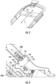
- the handle 104 can then be rotated between a plurality of different positions. In the embodiment illustrated in FIG. 4 , rotation can occur about the pivot axis PA resulting in the handle 104 rotating into and out of the page.
- a biasing element 136 can bias the engagement element 128 into the engagement interfaces 120.
- the biasing element 136 can include, for example, a spring. In a particular embodiment, the spring can extend between the link 132 or engagement element 128 and pull the engagement element 128 toward the work portion 102.
- the spring can have a suitable spring rate to pull the engagement element 128 into the engagement interfaces when the UEI 116 is released. That is, the spring rate of the spring can be configured to automatically bias the engagement element 128 into the engagement interface when no force is applied by the operator on the UEI 116. In further instances, the spring can assist the user in rotating the UEI 116 to the first position whereby the engagement element 128 is disposed in one or more of the engagement interfaces 120.
- the biasing element 136 can pass over the pivot axis PA, such as illustrated in FIG. 4 . That is, an upper portion of the biasing element 136 can be disposed on a first side of the pivot axis PA and a lower portion of the biasing element 136 can be disposed on a second side of the pivot axis PA.
- the biasing element 136 can be coupled to a member located at the pivot axis PA. That is, the biasing element 136 may not extend past, or may not extend substantially past, the pivot axis PA. For instance, referring to FIG.
- the biasing element 136 can be coupled with a rotatable interface, e.g., a bushing 138, about which the pivot axis PA is disposed.
- the rotatable interface can include the bushing 138 disposed on a pivot shaft 140.
- the pivot shaft 140 can be fixedly coupled to the work portion 102 of the lawn mower 100.
- the bushing 138 can be fixedly coupled to the handle 104.
- adjusting the handle 104 can cause the bushing 138 and handle 104 to rotate together about the pivot axis PA defined by the pivot shaft 140.
- the above-described locking mechanism can be included on both elongated members 108A and 108B. That is, the handle 104 and work portion 102 can be selectively secured together at fixed positions through both of the elongated members 108A and 108B.
- only one of the elongated members 108A or 108B has a locking mechanism and the other of the elongated members 108A or 108B does not include the described locking mechanism.
- the other of the elongated members 108A or 108B may be free to move independent of the position of the UEI 116.
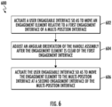
- FIG. 6 illustrates a flow chart of a method 600 of adjusting a handle assembly of a power tool.
- the method 600 includes a step 602 of actuating a user engageable interface so as to move an engagement element relative to a first engagement interface of a multi-position interface.
- the step 602 may be performed by rotating the user engageable interface, translating the user engageable interface in a linear direction, or through a combination thereof.
- the step 602 may require the operator to release a lock or other mechanism configured to prevent accidental movement of the user engageable interface.
- step 602 may be performed while the power tool is in the on position, the off position, static, moving, or at any other time during operation of the power tool.
- the operator may cause a biasing element, e.g., the aforementioned spring, to elongate, creating force to return the user engageable interface to the original position.
- a biasing element e.g., the aforementioned spring
- the method 600 can further include a step 604 of adjusting the angular orientation of the handle assembly after the engagement element is clear of the first engagement interface. That is, the operator can reposition the handle assembly after completion, or substantial completion, of step 602. As described herein, adjustment may occur by rotating the handle about a pivot axis. The operator may rotate the handle to the desired position at step 604. In certain instances, the operator may maintain the user engageable interface in an actuated position during step 604. In other instances, the operator may be able to release the user engageable interface during step 604. That is, the user engageable interface may be configured to remain in the unlocked position to permit adjustment of the handle without requiring the operator maintain the user engageable interface in the unlocked position.
- the method 600 can further include a step 606 of actuating the user engageable interface so as to move the engagement element to the multi-position interface at a second engagement interface thereof.
- the step 606 can be performed by positively moving the user engageable interface or releasing the user engageable interface such that it returns automatically to the locked position.
- the step 606 can be performed after the operator has selected an appropriate position of the handle.
- Steps 602 or 606 can cause one or more connective members extending between the user engageable interface to move the engagement element relative to the multi-position interface, causing the engagement element to seat or pull therefrom.
- movement of the engagement element can occur in a linear direction.
- Step 602 can cause the engagement element to linearly translate in a first direction while step 606 can cause the engagement element to linearly translate in a second direction opposite, or generally opposite, the first direction.
Landscapes
- Life Sciences & Earth Sciences (AREA)
- Environmental Sciences (AREA)
- Harvester Elements (AREA)
- Details Of Spanners, Wrenches, And Screw Drivers And Accessories (AREA)
Claims (13)
- Griffanordnung für einen Rasenmäher, die Griffanordnung umfassend:
einen Griff (104), der sich von einem Arbeitsabschnitt des Rasenmähers erstreckt, der Griff (104) umfassend:ein Griffelement (106), das konfiguriert ist, um von einem Benutzer beim Betreiben des Rasenmähers ergriffen zu werden; undmindestens ein längliches Element (108A, 108B), das sich zwischen dem Arbeitsabschnitt des Rasenmähers und des Griffelements (106) erstreckt;eine Mehrpositionsschnittstelle (118), die von dem Griffelement (106) beabstandet ist, wobei die Mehrpositionsschnittstelle (118) eine Vielzahl von Eingriffsschnittstellen (120) definiert;ein Eingriffselement (128), das konfiguriert ist, um sich relativ zu der Mehrpositionsschnittstelle (118) zu bewegen und mit der Vielzahl von Eingriffsschnittstellen (120) selektiv in Eingriff gebracht zu werden; undeine von dem Benutzer ergreifbare Schnittstelle (116), die konfiguriert ist, um das Eingriffselement (128) in den und aus dem Eingriff mit der Vielzahl von Eingriffsschnittstellen (120) der Mehrpositionsschnittstelle (118) selektiv zu bewegen,wobei die Griffanordnung zwischen einer Vielzahl von Winkelausrichtungen winkelig neu positionierbar ist, wenn das Eingriffselement (128) nicht innerhalb einer der Vielzahl von Eingriffsschnittstellen (120) eingerichtet ist, und wobei die Griffanordnung an dem Arbeitsabschnitt des Rasenmähers winkelig befestigt ist, wenn das Eingriffselement (128) innerhalb einer oder mehrerer der Vielzahl von Eingriffsschnittstellen (120) eingerichtet ist,dadurch gekennzeichnet, dass die von dem Benutzer ergreifbare Schnittstelle (116) an dem oder angrenzend an das Griffelement (106) eingerichtet ist, wobei das Eingriffselement (128) mit der von dem Benutzer ergreifbaren Schnittstelle (116) durch eines oder mehrere Verbindungselemente (130), die sich entlang des mindestens einen länglichen Elements (108A, 108B) erstrecken, wirkgekoppelt ist. - Griffanordnung nach Anspruch 1, wobei die Mehrpositionsschnittstelle (118) einen Körper umfasst, und die Vielzahl von Eingriffsschnittstellen (120) jeweils einen Schlitz, der in dem Körper ausgebildet ist, umfassen, und wobei das Eingriffselement (128) konfiguriert ist, um sich in die Schlitze in dem Körper der Mehrpositionsschnittstelle (118) hinein und aus ihnen heraus selektiv zu bewegen.
- Griffanordnung nach Anspruch 1 oder 2, wobei das Eingriffselement (128) konfiguriert ist, um sich in eine im Allgemeinen Linearrichtung zu verschieben, beim Bewegen in den und aus dem Eingriff mit der Vielzahl von Eingriffsschnittstellen (120) der Mehrpositionsschnittstelle (118).
- Griffanordnung nach Anspruch 1, 2 oder 3, wobei die von dem Benutzer ergreifbare Schnittstelle (116) konfiguriert ist, um das Eingriffselement (128) in den und aus dem Eingriff mit der Vielzahl von Eingriffsschnittstellen (120) durch Linearverschiebung Drehbewegung oder beides, selektiv zu bewegen.
- Griffanordnung nach Anspruch 1, 2, 3 oder 4, ferner umfassend ein Vorspannelement, das konfiguriert ist, um das Eingriffselement (128) in mindestens eine der Vielzahl von Eingriffsschnittstellen (120) vorzuspannen.
- Griffanordnung nach Anspruch 5, wobei die Mehrpositionsschnittstelle (118) zwischen dem Vorspannelement und dem Griffelement (106) eingerichtet ist.
- Griffanordnung nach den Ansprüchen 1, 2, 3, 4, 5 oder 6, wobei der Griff (104) um einen Drehpunkt schwenkbar ist, und wobei die Mehrpositionsschnittstelle (118) zwischen dem Drehpunkt und dem Griffelement (106) eingerichtet ist.
- Griffanordnung nach Anspruch 1, 2, 3, 4, 5, 6 oder 7, wobei das mindestens eine längliche Element (108A, 108B) zwei längliche Elemente (108A, 108B) umfasst, wobei die zwei länglichen Elemente (108A, 108B) auf gegenüberliegenden Seiten einer Messeranordnung des Rasenmähers eingerichtet sind.
- Griffanordnung für einen Rasenmäher nach Anspruch 1, die Griffanordnung umfassend:die Mehrpositionsschnittstelle (118), die mit einem Arbeitsabschnitt des Rasenmähers gekoppelt ist; unddas Eingriffselement (128), das mit der von dem Benutzer ergreifbaren Schnittstelle (116) gekoppelt ist und zwischen einer Vielzahl von Schlitzen, die in der Mehrpositionsschnittstelle (118) eingerichtet sind, selektiv anpassbar ist, wobei das Eingriffselement (128) durch eine Feder in die Schlitze vorgespannt und aus den Schlitzen bei Betätigung der von dem Benutzer eingreifbaren Schnittstelle (116) linear verschiebbar ist.
- Griffanordnung nach Anspruch 9, ferner umfassend ein oder mehrere Verbindungselemente (130), die zwischen der von dem Benutzer eingreifbaren Schnittstelle (116) und dem Eingriffselement (128) direkt gekoppelt sind, wobei sich das eine oder die mehreren Verbindungselemente (130) zwischen dem Arbeitsabschnitt des Rasenmähers und einem Griffelement (106) des Abschnitts des Griffs (104) des Rasenmähers erstrecken.
- Griffanordnung nach Anspruch 9 oder 10, wobei mindestens einer der Schlitze eine Form definiert, die konfiguriert ist, um eine enge Passung mit dem Eingriffselement (128) aufzuweisen.
- Griffanordnung nach Anspruch 9, 10 oder 11, wobei der Griff (104) relativ zu dem Arbeitsabschnitt des Rasenmähers drehbar ist, wenn das Eingriffselement (128) aus der Vielzahl von Schlitzen in der Mehrpositionsschnittstelle (118) verschoben wird.
- Verfahren zum Anpassen einer Griffanordnung eines Rasenmähers, das Verfahren umfassend:Betätigen einer von dem Benutzer ergreifbaren Schnittstelle (116), um ein Eingriffselement (128) relativ zu einer ersten Eingriffsschnittstelle (120) einer Mehrpositionsschnittstelle (118) zu bewegen;Anpassen einer Winkelausrichtung der Griffanordnung, nachdem das Eingriffselement (128) von der ersten Eingriffsschnittstelle (120) frei ist; undBetätigen der von dem Benutzer ergreifbaren Schnittstelle (116), um das Eingriffselement (128) zu der Mehrpositionsschnittstelle (118) an einer zweiten Eingriffsschnittstelle (120) der Mehrpositionsschnittstelle (118) zu bewegen, wobei die von dem Benutzer ergreifbare Schnittstelle (116) an dem oder angrenzend an das Griffelement (106) der Griffanordnung eingerichtet ist, wobei das Eingriffselement (128) mit der von dem Benutzer ergreifbaren Schnittstelle (116) durch eines oder mehrere Verbindungselemente (130), die sich entlang des mindestens einen länglichen Elements (108A, 108B) erstrecken, wirkgekoppelt ist.
Applications Claiming Priority (1)
| Application Number | Priority Date | Filing Date | Title |
|---|---|---|---|
| US17/174,954 US12329063B2 (en) | 2021-02-12 | 2021-02-12 | Handle assembly for a power tool |
Publications (2)
| Publication Number | Publication Date |
|---|---|
| EP4079138A1 EP4079138A1 (de) | 2022-10-26 |
| EP4079138B1 true EP4079138B1 (de) | 2024-07-24 |
Family
ID=80001279
Family Applications (1)
| Application Number | Title | Priority Date | Filing Date |
|---|---|---|---|
| EP22152877.1A Active EP4079138B1 (de) | 2021-02-12 | 2022-01-24 | Handgriffanordnung für ein elektrowerkzeug |
Country Status (4)
| Country | Link |
|---|---|
| US (1) | US12329063B2 (de) |
| EP (1) | EP4079138B1 (de) |
| CN (1) | CN114916304A (de) |
| AU (1) | AU2022200757B2 (de) |
Families Citing this family (7)
| Publication number | Priority date | Publication date | Assignee | Title |
|---|---|---|---|---|
| WO2022272151A1 (en) * | 2021-06-24 | 2022-12-29 | Mtd Products Inc | Foldable handles for high-efficiency turf maintenance tool |
| US20240081180A1 (en) * | 2022-09-14 | 2024-03-14 | Mtd Products Inc | Compact folding handles and electronic control system for high-efficiency turf maintenance tool |
| USD1120032S1 (en) * | 2023-06-16 | 2026-03-24 | Andreas Stihl Ag & Co. Kg | Lawnmower |
| USD1118704S1 (en) * | 2023-06-16 | 2026-03-17 | Andreas Stihl Ag & Co. Kg | Lawnmower |
| USD1117354S1 (en) * | 2023-06-16 | 2026-03-10 | Andreas Stihl Ag & Co. Kg | Lawnmower |
| US20240426066A1 (en) * | 2023-06-23 | 2024-12-26 | Milwaukee Electric Tool Corporation | Construction tool handle |
| USD1117355S1 (en) * | 2023-12-22 | 2026-03-10 | Andreas Stihl Ag & Co. Kg | Lawnmower |
Family Cites Families (132)
| Publication number | Priority date | Publication date | Assignee | Title |
|---|---|---|---|---|
| US2786694A (en) | 1955-06-20 | 1957-03-26 | Motor Wheel Corp | Adjustable mounting for handle of lawn mowers |
| US2957295A (en) | 1958-05-01 | 1960-10-25 | Briggs & Stratton Corp | Grass clipping discharge for power lawn mower |
| US2966365A (en) | 1958-12-08 | 1960-12-27 | Atlas Tool & Mfg Co | Lawn mower handle |
| US3145519A (en) | 1962-06-18 | 1964-08-25 | Sears Roebuck & Co | Rotary lawn mower |
| US3481123A (en) | 1967-04-10 | 1969-12-02 | Black & Decker Mfg Co | Handle mount for lawn mower |
| US3593505A (en) | 1968-09-04 | 1971-07-20 | Toro Mfg Corp | Mower motor cooling system |
| DE1936010A1 (de) | 1969-07-15 | 1971-01-28 | Wolf Geraete Gmbh | Rasenmaeher |
| ZA706066B (en) | 1970-04-08 | 1971-05-27 | Victa Ltd | A safety flap arrangement for discharge apertures in rotary lawnmower baseplates |
| DE3062240D1 (en) | 1979-02-03 | 1983-04-14 | Ering Metallwaren | Lawn mower |
| EP0037871B1 (de) | 1980-04-15 | 1983-11-09 | Flymo Limited | Sammelzubehör für einen von einem Luftkissen getragenen Rasenmäher |
| US4392538A (en) * | 1981-01-29 | 1983-07-12 | Roper Corporation | Adjustable handle assembly for walk-behind garden implement |
| JPS5959113A (ja) | 1982-09-25 | 1984-04-04 | 株式会社アーレスティ | 芝刈機 |
| US4944142A (en) | 1988-08-22 | 1990-07-31 | Honda Giken Kogyo Kabushiki Kaisha | Power lawnmower construction |
| US4916887A (en) | 1989-08-14 | 1990-04-17 | Excel Industries, Inc. | Rotary mulching mower |
| US5163275A (en) | 1990-06-01 | 1992-11-17 | Hare Ronald G | Pivoting handle mounting arrangement for lawn mower |
| GB9022636D0 (en) | 1990-10-18 | 1990-11-28 | Black & Decker Inc | Lawn mower |
| US5109656A (en) | 1991-02-11 | 1992-05-05 | Zimmer Richard T | Rotary cutting mechanism |
| GB2255263B (en) | 1991-04-26 | 1994-08-31 | Black & Decker Inc | Lawn mower |
| US5259176A (en) | 1992-02-24 | 1993-11-09 | Honda Giken Kogyo Kabushiki Kaisha | Cotter device for lawn mower |
| GB9205611D0 (en) | 1992-03-14 | 1992-04-29 | Black & Decker Inc | Braking system |
| US5894717A (en) | 1996-01-05 | 1999-04-20 | Honda Giken Kogyo Kabushiki Kaisha | Mulching mower |
| US5890354A (en) | 1996-08-30 | 1999-04-06 | Ransomes America Corporation | Rotary lawn mower mulching deck |
| US5809765A (en) | 1997-03-17 | 1998-09-22 | Allied Products Corporation | Counterrotation mulching mower and blade assembly |
| US5960619A (en) | 1997-06-03 | 1999-10-05 | Sunbeam Corporation Limited | Mulching disc for a lawn mower |
| GB2334421B (en) | 1998-02-23 | 2002-11-13 | Electrolux Outdoor Prod Ltd | Lawnmower |
| CN2381113Y (zh) | 1999-06-15 | 2000-06-07 | 新疆联合机械(集团)有限责任公司 | 自走式收割机四轮驱动装置 |
| JP2002029274A (ja) | 2000-07-14 | 2002-01-29 | Chikusui Canycom Inc | 草刈り機における走行伝動機構 |
| US6449933B1 (en) | 2000-09-29 | 2002-09-17 | Kuboto Corporation | Lawn mower |
| JP4603142B2 (ja) | 2000-10-11 | 2010-12-22 | 株式会社オーレック | 草刈機 |
| US20020069631A1 (en) | 2000-12-13 | 2002-06-13 | Colin Dyke | Vegetation cutter having vortex inducing blade system |
| US20020189137A1 (en) | 2001-04-25 | 2002-12-19 | Cox C. Paul | Walk-behind implement having forward and reverse drives and a method of operation therefor |
| US20030182919A1 (en) | 2002-03-28 | 2003-10-02 | Baumann James R. | Deck assembly for a self-propelled, walk-behind rotary lawn mower |
| US6732828B1 (en) | 2002-10-22 | 2004-05-11 | Robert Abend | Hydraulically driven vehicle |
| US7677344B2 (en) | 2003-08-05 | 2010-03-16 | Medina Luis M | Hybrid remote control lawn mower |
| US7231755B2 (en) | 2004-03-01 | 2007-06-19 | The Toro Company | Walk-behind implement and handle assembly release apparatus for use with same |
| US7347434B2 (en) | 2004-07-20 | 2008-03-25 | Briggs & Stratton Corporation | Four-wheel steering assembly |
| JP2006067918A (ja) | 2004-09-02 | 2006-03-16 | Honda Motor Co Ltd | 芝刈機 |
| DE502005004816D1 (de) | 2005-08-09 | 2008-09-04 | Wolf Outils | Handgeführtes Bodenbearbeitungsgerät, insbesondere Rasenmäher |
| US20070193243A1 (en) | 2006-02-10 | 2007-08-23 | Schmidt James R | Combine Harvester Draper Header Having Flexible Cutterbar |
| US20110173941A1 (en) | 2006-05-26 | 2011-07-21 | Leif Persson | Power Transmission for a Lawn Mower and a Lawn Mower Provided with Such a Transmission |
| FR2914141B1 (fr) | 2007-03-30 | 2009-06-05 | Iseki Agricult Mach | Tondeuse a gazon automotrice |
| ITMI20071290A1 (it) | 2007-06-28 | 2008-12-29 | Ma Ri Na Systems S R L | Tosaerba a trazione posteriore dotato di dispositivo di innesto della trazione integrale |
| CN101836540A (zh) | 2009-03-19 | 2010-09-22 | 陈建水 | 一种割草机变速箱 |
| US20110036065A1 (en) | 2009-08-11 | 2011-02-17 | Yen Wen Wong | Lawn mower powered by a compression-ignited combustion engine that can use multiple fuel types |
| CN201518585U (zh) | 2009-09-11 | 2010-07-07 | 镇江益林金刚石工具有限公司 | 一种组合式割草锯片 |
| BR112012023053A2 (pt) | 2010-03-12 | 2017-07-25 | Forage Innovations Bv | "máquina agrícola, segadora e método para orientar uma caixa de engrenagens traseira em uma segadora" |
| WO2011131031A1 (zh) | 2010-04-21 | 2011-10-27 | 苏州宝时得电动工具有限公司 | 割草机和控制割草机自驱操作的控制方法 |
| AU2011360270B9 (en) | 2011-02-21 | 2017-04-13 | Husqvarna Ab | Handle control arrangement of a walk-behind lawn mower |
| CN202172591U (zh) | 2011-07-14 | 2012-03-28 | 重庆軎门特机电制造有限公司 | 草坪机及其刀具 |
| US9433147B2 (en) * | 2011-11-03 | 2016-09-06 | Briggs & Stratton Corporation | Vertically storable engine and mower |
| US9462747B2 (en) | 2011-11-03 | 2016-10-11 | Brigs & Stratton Corporation | Vertically storable engine and mower |
| US20140360740A1 (en) | 2012-01-23 | 2014-12-11 | Husqvarna Ab | Walk behind power equipment handle height adjuster |
| EP2814312B1 (de) | 2012-02-13 | 2019-09-11 | Husqvarna Ab | Handgeführter mäher mit allradantrieb |
| CN102523817B (zh) | 2012-02-22 | 2014-03-12 | 南京德朔实业有限公司 | 多档位把手机构及包含该把手机构的割草机 |
| EP2656720B1 (de) | 2012-04-24 | 2015-11-04 | Robert Bosch GmbH | Messerschutz für einen Rasenmäher |
| CN103843516B (zh) | 2012-11-28 | 2016-03-30 | 苏州宝时得电动工具有限公司 | 割草机的切割装置以及切割装置的安装方法 |
| JP5852954B2 (ja) | 2012-12-28 | 2016-02-03 | 金星園芸工業株式会社 | 手動式芝刈機 |
| US8875833B2 (en) | 2012-12-31 | 2014-11-04 | Kawasaki Jukogyo Kabushiki Kaisha | Utility vehicle |
| US9386743B2 (en) * | 2013-03-15 | 2016-07-12 | Husqvarna Ab | Door lift and handle for walk behind mower |
| US8925293B2 (en) * | 2013-05-07 | 2015-01-06 | Ariens Company | Adjustable handle for outdoor power equipment |
| CN203407205U (zh) | 2013-06-22 | 2014-01-29 | 苏州金威特工具有限公司 | 一种把手可调割草机 |
| CN103283375A (zh) | 2013-06-22 | 2013-09-11 | 苏州金威特工具有限公司 | 一种把手可调割草机 |
| CN103283380A (zh) | 2013-06-26 | 2013-09-11 | 苏州金威特工具有限公司 | 一种双层刀片割草机 |
| CN203407212U (zh) | 2013-06-26 | 2014-01-29 | 苏州金威特工具有限公司 | 一种双层刀片割草机 |
| CN203344655U (zh) | 2013-07-13 | 2013-12-18 | 临颍县颍机机械制造有限公司 | 轮边减速器四驱抓草机 |
| CN203723096U (zh) | 2014-02-27 | 2014-07-23 | 福田雷沃国际重工股份有限公司 | 中置还田玉米收获机的四轮驱动装置 |
| JP6238802B2 (ja) | 2014-03-17 | 2017-11-29 | 株式会社クボタ | 歩行型作業機 |
| JP6243273B2 (ja) | 2014-03-27 | 2017-12-06 | 本田技研工業株式会社 | 芝刈機 |
| CN203851475U (zh) | 2014-04-04 | 2014-10-01 | 宁波佳一园林机械有限公司 | 一种扶手高度限位结构 |
| JP6322061B2 (ja) | 2014-06-16 | 2018-05-09 | 株式会社クボタ | モーア |
| CN203951828U (zh) | 2014-06-24 | 2014-11-26 | 苏州宝时得电动工具有限公司 | 割草机 |
| CN203984888U (zh) | 2014-06-30 | 2014-12-10 | 禄玉峰 | 一种新型多功能耕作机 |
| FR3025692B1 (fr) | 2014-09-15 | 2016-11-04 | Pellenc Sa | Tondeuse a roues pour conducteur marchant |
| CN104686083B (zh) | 2014-10-27 | 2016-11-30 | 青岛科瑞特激光设备有限公司 | 收割机用两档四轮驱动液压无级变速驱动桥总成 |
| CN204362533U (zh) | 2014-12-10 | 2015-06-03 | 重庆科业动力机械制造有限公司 | 带升降扶手架的微耕机 |
| US9848531B2 (en) * | 2015-01-13 | 2017-12-26 | The Toro Company | Vertical storage grounds maintenance apparatus |
| US9677648B2 (en) | 2015-01-14 | 2017-06-13 | The Toro Company | Walk-behind power equipment unit having all-wheel drive control system |
| US9439352B2 (en) | 2015-02-02 | 2016-09-13 | Husqvarna Ab | Handle height adjuster for walk behind mower |
| CN106171253B (zh) | 2015-05-05 | 2020-06-23 | 南京德朔实业有限公司 | 割草机 |
| USD755858S1 (en) | 2015-05-15 | 2016-05-10 | Sean C. Brown | Blade assembly |
| CN204976318U (zh) | 2015-07-27 | 2016-01-20 | 江苏科瑞欣机械有限公司 | 一种带操作把手调高功能的研磨机 |
| FR3039967B1 (fr) | 2015-08-13 | 2017-07-28 | Pellenc Sa | Tondeuse agraire electrique a frein de stationnement electromagnetique. |
| CN108349367B (zh) | 2015-10-27 | 2021-04-27 | 密歇根大学董事会 | 具有动态离合器的混合动力全轮驱动系统 |
| CN205207090U (zh) | 2015-12-12 | 2016-05-04 | 浙江大有机电科技有限公司 | 便于扶手角度调节的空压机 |
| US9480200B1 (en) | 2016-01-27 | 2016-11-01 | Arthur Gary Patridge | Multi-blade lawn mower cutting system with overlapping cutting circles |
| JP6654929B2 (ja) | 2016-02-29 | 2020-02-26 | 本田技研工業株式会社 | 芝刈機 |
| JP6147881B1 (ja) | 2016-02-29 | 2017-06-14 | 本田技研工業株式会社 | 芝刈機 |
| JP6313348B2 (ja) | 2016-02-29 | 2018-04-18 | 本田技研工業株式会社 | 芝刈機 |
| CN106042916A (zh) | 2016-06-13 | 2016-10-26 | 覃志明 | 一种微耕机的四轮驱动装置 |
| US10123478B2 (en) | 2016-06-28 | 2018-11-13 | The Toro Company | Walk power mower with biased handle |
| US10039229B2 (en) | 2016-06-28 | 2018-08-07 | The Toro Company | Walk power mower having forward and reverse traction drive |
| US10111381B2 (en) | 2016-06-28 | 2018-10-30 | The Toro Company | Walk power mower with transmission providing both forward and reverse propulsion |
| US11172610B2 (en) | 2016-08-31 | 2021-11-16 | Kaaz Corporation | Transmission for lawn mower |
| CA3037676A1 (en) | 2016-09-21 | 2018-03-29 | Mtd Products Inc | Control assembly for a walk-behind mower |
| CN206260310U (zh) | 2016-12-12 | 2017-06-20 | 山东牧神机械有限责任公司 | 一种玉米收获机的四驱传动装置 |
| JP2018102235A (ja) | 2016-12-27 | 2018-07-05 | 本田技研工業株式会社 | カッタブレード及び芝刈機 |
| CN106818024A (zh) * | 2017-01-03 | 2017-06-13 | 天佑电器(苏州)有限公司 | 园林工具推杆机构及具有该机构的园林工具 |
| DE102017205320A1 (de) * | 2017-03-29 | 2018-10-04 | Robert Bosch Gmbh | Bodenbearbeitungsgerät |
| CN206808087U (zh) | 2017-04-18 | 2017-12-29 | 常州格力博有限公司 | 双刀割草机 |
| CN206690874U (zh) | 2017-05-04 | 2017-12-01 | 吉林开普科立辉动力有限公司 | 一种用于多功能保障车的传动装置 |
| CN117256299A (zh) | 2017-06-23 | 2023-12-22 | 创科(澳门离岸商业服务)有限公司 | 割草机 |
| CN207235370U (zh) | 2017-07-27 | 2018-04-17 | 宁波万融电器有限公司 | 一种微耕机 |
| CN207269314U (zh) | 2017-08-03 | 2018-04-27 | 重庆万虎农机有限公司 | 一种微耕机及其扶手架旋转调节机构 |
| US20190045707A1 (en) | 2017-08-11 | 2019-02-14 | Arthur Gary Patridge | Lawn mower blade arrangements |
| AU2018359553A1 (en) * | 2017-11-03 | 2020-03-19 | Mtd Products Inc | Drop handle mower |
| CN207589549U (zh) | 2017-11-15 | 2018-07-10 | 天津拖拉机制造有限公司 | 一种玉米收获机四轮液压驱动装置 |
| CN208285836U (zh) | 2017-11-24 | 2018-12-28 | 苏州宝时得电动工具有限公司 | 割草机 |
| CN108450122A (zh) | 2017-12-15 | 2018-08-28 | 雷可强 | 一种高效割草机 |
| US10624262B2 (en) | 2018-03-29 | 2020-04-21 | Honda Motor Co., Ltd. | Closed-loop electronic slipping belt transmission speed control system for a walk-behind lawn mower |
| EP3549429B1 (de) | 2018-04-06 | 2021-10-27 | LG Electronics Inc. | Rasenmäherroboter |
| CN208113339U (zh) | 2018-04-11 | 2018-11-20 | 宁波好使特电器有限公司 | 一种手推式割草机的高度调节机构 |
| US12471526B2 (en) * | 2018-05-01 | 2025-11-18 | The Toro Company | Grounds maintenance apparatus with folding handle |
| CN110651586A (zh) | 2018-06-30 | 2020-01-07 | 湖北智权专利技术应用开发有限公司 | 一种软轴传动全地形遥控割草机 |
| CN108834443A (zh) | 2018-08-15 | 2018-11-20 | 台州市坤山机电股份有限公司 | 一种便于操作使用的微耕机 |
| DE102018216089A1 (de) | 2018-09-20 | 2020-03-26 | KommTek Intelligente Lösungen GmbH | Antrieb für ein Allradfahrzeug mit vier Rädern |
| EP3821692B1 (de) | 2018-09-27 | 2024-07-31 | Nanjing Chervon Industry Co., Ltd. | Rasenmäher |
| CN209299732U (zh) | 2018-11-07 | 2019-08-27 | 苏州金莱克精密机械有限公司 | 一种可调高并且能够二次折叠的电动割草机 |
| CN109392415B (zh) | 2018-11-07 | 2024-03-22 | 苏州金莱克精密机械有限公司 | 一种可调高并且能够二次折叠的电动割草机 |
| JP6904323B2 (ja) | 2018-11-28 | 2021-07-14 | 井関農機株式会社 | 作業車両 |
| CN111328557A (zh) | 2018-12-18 | 2020-06-26 | 苏州宝时得电动工具有限公司 | 割草机 |
| CN109496564B (zh) | 2018-12-28 | 2023-08-25 | 敦化市方正农业机械装备制造有限责任公司 | 一种玉米收割机动力传动系统 |
| US11535099B2 (en) | 2019-01-07 | 2022-12-27 | Kanzaki Kokyukoki Manufacturing Co., Ltd. | Power transmission device for a four-wheel drive vehicle |
| MX2020000519A (es) | 2019-01-31 | 2020-08-20 | Techtronic Cordless Gp | Herramienta electrica que tiene altura o velocidad variable. |
| CN210093998U (zh) | 2019-05-09 | 2020-02-21 | 浙江派尼尔科技股份有限公司 | 一种步进式草坪机用后驱式行星齿轮自走装置 |
| US12016267B2 (en) | 2019-05-28 | 2024-06-25 | The Toro Company | Walk power mower with ground speed responsive to force applied to a handle grip by the operator |
| CN210694954U (zh) | 2019-06-26 | 2020-06-09 | 苏州金莱克精密机械有限公司 | 一种割草机 |
| EP3766328B1 (de) * | 2019-07-16 | 2023-04-12 | Nanjing Chervon Industry Co., Ltd. | Handgetriebenes elektrowerkzeug |
| CN112238422B (zh) * | 2019-07-16 | 2022-08-02 | 南京泉峰科技有限公司 | 手推式动力工具 |
| US11317561B2 (en) | 2019-10-22 | 2022-05-03 | Honda Motor Co., Ltd. | Lawnmower propulsion system for use with DC power source |
| WO2021113306A1 (en) * | 2019-12-02 | 2021-06-10 | Mtd Products Inc | Adjustable handle assembly for a walk-behind mower |
| CN212643450U (zh) | 2020-06-23 | 2021-03-02 | 山东巨明机械有限公司 | 一种收获机械用带高低速的多挡四驱变速箱 |
| CN212573551U (zh) | 2020-07-02 | 2021-02-23 | 格力博(江苏)股份有限公司 | 一种四驱自走组件以及割草机 |
-
2021
- 2021-02-12 US US17/174,954 patent/US12329063B2/en active Active
-
2022
- 2022-01-24 EP EP22152877.1A patent/EP4079138B1/de active Active
- 2022-02-04 AU AU2022200757A patent/AU2022200757B2/en active Active
- 2022-02-09 CN CN202210133173.5A patent/CN114916304A/zh active Pending
Also Published As
| Publication number | Publication date |
|---|---|
| AU2022200757B2 (en) | 2023-11-16 |
| AU2022200757A1 (en) | 2022-09-01 |
| EP4079138A1 (de) | 2022-10-26 |
| CN114916304A (zh) | 2022-08-19 |
| US20220256767A1 (en) | 2022-08-18 |
| US12329063B2 (en) | 2025-06-17 |
Similar Documents
| Publication | Publication Date | Title |
|---|---|---|
| EP4079138A1 (de) | Handgriffanordnung für ein elektrowerkzeug | |
| JP7371965B2 (ja) | 草刈装置 | |
| US5724875A (en) | Guard and control apparatuses for sliding compound miter saw | |
| EP0005540B1 (de) | Fadenschneider zum Beschneiden von Rasenkanten | |
| US20030150311A1 (en) | Remotely actuated beveling systems for a miter saw | |
| WO2000009298A9 (en) | Remote gripping or cutting apparatus having a rotatable head | |
| US6343668B1 (en) | Foldable control lever | |
| US20180050457A1 (en) | Cutting tool with blade and handle opening control mechanism | |
| WO2013097778A1 (zh) | 园林工具 | |
| DE60301002T2 (de) | Gehrungswinkelanschlagmechanismus für eine Gehrungssäge | |
| US20240397860A1 (en) | Grounds maintenance vehicle with adjustable implement angle | |
| EP2374585B1 (de) | Gehrungswinkelverstelleinrichtung für eine Kreissäge | |
| CA1255571A (en) | Hydraulic control valve with manual override | |
| US20030221321A1 (en) | Hedge shears | |
| EP1651026B1 (de) | Fadenschneider | |
| US11812693B2 (en) | Hand-propelled power tool | |
| EP2241396B1 (de) | Werkzeugmaschine, insbesondere Kappsäge. | |
| EP1935542B1 (de) | Werkzeugmaschine mit einer Rast- und Klemmeinrichtung | |
| DE202016105276U1 (de) | Schneidwerkzeug, insbesondere Heckenschere | |
| US20080030083A1 (en) | Hand-guided power tool and coupling of a hand-guided power tool | |
| EP2249989B1 (de) | Kappsäge mit nuttiefenanschlag | |
| EP1792533B1 (de) | Arbeitsgerät mit Griffeinheit | |
| EP3579683B1 (de) | Handhaltbares werkzeug | |
| US6754961B2 (en) | Shears | |
| WO2009097875A1 (de) | Kappsäge mit einer staubabsaugung und/oder einer verkleidung |
Legal Events
| Date | Code | Title | Description |
|---|---|---|---|
| PUAI | Public reference made under article 153(3) epc to a published international application that has entered the european phase |
Free format text: ORIGINAL CODE: 0009012 |
|
| STAA | Information on the status of an ep patent application or granted ep patent |
Free format text: STATUS: REQUEST FOR EXAMINATION WAS MADE |
|
| 17P | Request for examination filed |
Effective date: 20220124 |
|
| AK | Designated contracting states |
Kind code of ref document: A1 Designated state(s): AL AT BE BG CH CY CZ DE DK EE ES FI FR GB GR HR HU IE IS IT LI LT LU LV MC MK MT NL NO PL PT RO RS SE SI SK SM TR |
|
| RIC1 | Information provided on ipc code assigned before grant |
Ipc: A01D 34/68 20060101AFI20231212BHEP |
|
| REG | Reference to a national code |
Ref country code: DE Ref legal event code: R079 Free format text: PREVIOUS MAIN CLASS: A01D0034680000 Ipc: A01D0034820000 Ref country code: DE Ref legal event code: R079 Ref document number: 602022004678 Country of ref document: DE Free format text: PREVIOUS MAIN CLASS: A01D0034680000 Ipc: A01D0034820000 |
|
| GRAP | Despatch of communication of intention to grant a patent |
Free format text: ORIGINAL CODE: EPIDOSNIGR1 |
|
| STAA | Information on the status of an ep patent application or granted ep patent |
Free format text: STATUS: GRANT OF PATENT IS INTENDED |
|
| INTG | Intention to grant announced |
Effective date: 20240202 |
|
| RIC1 | Information provided on ipc code assigned before grant |
Ipc: A01D 34/82 20060101AFI20240122BHEP |
|
| GRAS | Grant fee paid |
Free format text: ORIGINAL CODE: EPIDOSNIGR3 |
|
| GRAA | (expected) grant |
Free format text: ORIGINAL CODE: 0009210 |
|
| STAA | Information on the status of an ep patent application or granted ep patent |
Free format text: STATUS: THE PATENT HAS BEEN GRANTED |
|
| AK | Designated contracting states |
Kind code of ref document: B1 Designated state(s): AL AT BE BG CH CY CZ DE DK EE ES FI FR GB GR HR HU IE IS IT LI LT LU LV MC MK MT NL NO PL PT RO RS SE SI SK SM TR |
|
| REG | Reference to a national code |
Ref country code: GB Ref legal event code: FG4D |
|
| REG | Reference to a national code |
Ref country code: CH Ref legal event code: EP |
|
| REG | Reference to a national code |
Ref country code: IE Ref legal event code: FG4D Ref country code: DE Ref legal event code: R096 Ref document number: 602022004678 Country of ref document: DE |
|
| REG | Reference to a national code |
Ref country code: LT Ref legal event code: MG9D |
|
| REG | Reference to a national code |
Ref country code: NL Ref legal event code: MP Effective date: 20240724 |
|
| PG25 | Lapsed in a contracting state [announced via postgrant information from national office to epo] |
Ref country code: PT Free format text: LAPSE BECAUSE OF FAILURE TO SUBMIT A TRANSLATION OF THE DESCRIPTION OR TO PAY THE FEE WITHIN THE PRESCRIBED TIME-LIMIT Effective date: 20241125 |
|
| REG | Reference to a national code |
Ref country code: AT Ref legal event code: MK05 Ref document number: 1705364 Country of ref document: AT Kind code of ref document: T Effective date: 20240724 |
|
| PG25 | Lapsed in a contracting state [announced via postgrant information from national office to epo] |
Ref country code: NL Free format text: LAPSE BECAUSE OF FAILURE TO SUBMIT A TRANSLATION OF THE DESCRIPTION OR TO PAY THE FEE WITHIN THE PRESCRIBED TIME-LIMIT Effective date: 20240724 |
|
| PG25 | Lapsed in a contracting state [announced via postgrant information from national office to epo] |
Ref country code: PT Free format text: LAPSE BECAUSE OF FAILURE TO SUBMIT A TRANSLATION OF THE DESCRIPTION OR TO PAY THE FEE WITHIN THE PRESCRIBED TIME-LIMIT Effective date: 20241125 Ref country code: NL Free format text: LAPSE BECAUSE OF FAILURE TO SUBMIT A TRANSLATION OF THE DESCRIPTION OR TO PAY THE FEE WITHIN THE PRESCRIBED TIME-LIMIT Effective date: 20240724 |
|
| PG25 | Lapsed in a contracting state [announced via postgrant information from national office to epo] |
Ref country code: NO Free format text: LAPSE BECAUSE OF FAILURE TO SUBMIT A TRANSLATION OF THE DESCRIPTION OR TO PAY THE FEE WITHIN THE PRESCRIBED TIME-LIMIT Effective date: 20241024 |
|
| PG25 | Lapsed in a contracting state [announced via postgrant information from national office to epo] |
Ref country code: GR Free format text: LAPSE BECAUSE OF FAILURE TO SUBMIT A TRANSLATION OF THE DESCRIPTION OR TO PAY THE FEE WITHIN THE PRESCRIBED TIME-LIMIT Effective date: 20241025 Ref country code: PL Free format text: LAPSE BECAUSE OF FAILURE TO SUBMIT A TRANSLATION OF THE DESCRIPTION OR TO PAY THE FEE WITHIN THE PRESCRIBED TIME-LIMIT Effective date: 20240724 Ref country code: FI Free format text: LAPSE BECAUSE OF FAILURE TO SUBMIT A TRANSLATION OF THE DESCRIPTION OR TO PAY THE FEE WITHIN THE PRESCRIBED TIME-LIMIT Effective date: 20240724 |
|
| PG25 | Lapsed in a contracting state [announced via postgrant information from national office to epo] |
Ref country code: BG Free format text: LAPSE BECAUSE OF FAILURE TO SUBMIT A TRANSLATION OF THE DESCRIPTION OR TO PAY THE FEE WITHIN THE PRESCRIBED TIME-LIMIT Effective date: 20240724 |
|
| PG25 | Lapsed in a contracting state [announced via postgrant information from national office to epo] |
Ref country code: LV Free format text: LAPSE BECAUSE OF FAILURE TO SUBMIT A TRANSLATION OF THE DESCRIPTION OR TO PAY THE FEE WITHIN THE PRESCRIBED TIME-LIMIT Effective date: 20240724 |
|
| PG25 | Lapsed in a contracting state [announced via postgrant information from national office to epo] |
Ref country code: AT Free format text: LAPSE BECAUSE OF FAILURE TO SUBMIT A TRANSLATION OF THE DESCRIPTION OR TO PAY THE FEE WITHIN THE PRESCRIBED TIME-LIMIT Effective date: 20240724 Ref country code: IS Free format text: LAPSE BECAUSE OF FAILURE TO SUBMIT A TRANSLATION OF THE DESCRIPTION OR TO PAY THE FEE WITHIN THE PRESCRIBED TIME-LIMIT Effective date: 20241124 |
|
| PG25 | Lapsed in a contracting state [announced via postgrant information from national office to epo] |
Ref country code: HR Free format text: LAPSE BECAUSE OF FAILURE TO SUBMIT A TRANSLATION OF THE DESCRIPTION OR TO PAY THE FEE WITHIN THE PRESCRIBED TIME-LIMIT Effective date: 20240724 |
|
| PG25 | Lapsed in a contracting state [announced via postgrant information from national office to epo] |
Ref country code: RS Free format text: LAPSE BECAUSE OF FAILURE TO SUBMIT A TRANSLATION OF THE DESCRIPTION OR TO PAY THE FEE WITHIN THE PRESCRIBED TIME-LIMIT Effective date: 20241024 Ref country code: ES Free format text: LAPSE BECAUSE OF FAILURE TO SUBMIT A TRANSLATION OF THE DESCRIPTION OR TO PAY THE FEE WITHIN THE PRESCRIBED TIME-LIMIT Effective date: 20240724 |
|
| PG25 | Lapsed in a contracting state [announced via postgrant information from national office to epo] |
Ref country code: RS Free format text: LAPSE BECAUSE OF FAILURE TO SUBMIT A TRANSLATION OF THE DESCRIPTION OR TO PAY THE FEE WITHIN THE PRESCRIBED TIME-LIMIT Effective date: 20241024 Ref country code: PL Free format text: LAPSE BECAUSE OF FAILURE TO SUBMIT A TRANSLATION OF THE DESCRIPTION OR TO PAY THE FEE WITHIN THE PRESCRIBED TIME-LIMIT Effective date: 20240724 Ref country code: NO Free format text: LAPSE BECAUSE OF FAILURE TO SUBMIT A TRANSLATION OF THE DESCRIPTION OR TO PAY THE FEE WITHIN THE PRESCRIBED TIME-LIMIT Effective date: 20241024 Ref country code: LV Free format text: LAPSE BECAUSE OF FAILURE TO SUBMIT A TRANSLATION OF THE DESCRIPTION OR TO PAY THE FEE WITHIN THE PRESCRIBED TIME-LIMIT Effective date: 20240724 Ref country code: IS Free format text: LAPSE BECAUSE OF FAILURE TO SUBMIT A TRANSLATION OF THE DESCRIPTION OR TO PAY THE FEE WITHIN THE PRESCRIBED TIME-LIMIT Effective date: 20241124 Ref country code: HR Free format text: LAPSE BECAUSE OF FAILURE TO SUBMIT A TRANSLATION OF THE DESCRIPTION OR TO PAY THE FEE WITHIN THE PRESCRIBED TIME-LIMIT Effective date: 20240724 Ref country code: GR Free format text: LAPSE BECAUSE OF FAILURE TO SUBMIT A TRANSLATION OF THE DESCRIPTION OR TO PAY THE FEE WITHIN THE PRESCRIBED TIME-LIMIT Effective date: 20241025 Ref country code: FI Free format text: LAPSE BECAUSE OF FAILURE TO SUBMIT A TRANSLATION OF THE DESCRIPTION OR TO PAY THE FEE WITHIN THE PRESCRIBED TIME-LIMIT Effective date: 20240724 Ref country code: ES Free format text: LAPSE BECAUSE OF FAILURE TO SUBMIT A TRANSLATION OF THE DESCRIPTION OR TO PAY THE FEE WITHIN THE PRESCRIBED TIME-LIMIT Effective date: 20240724 Ref country code: BG Free format text: LAPSE BECAUSE OF FAILURE TO SUBMIT A TRANSLATION OF THE DESCRIPTION OR TO PAY THE FEE WITHIN THE PRESCRIBED TIME-LIMIT Effective date: 20240724 Ref country code: AT Free format text: LAPSE BECAUSE OF FAILURE TO SUBMIT A TRANSLATION OF THE DESCRIPTION OR TO PAY THE FEE WITHIN THE PRESCRIBED TIME-LIMIT Effective date: 20240724 |
|
| PG25 | Lapsed in a contracting state [announced via postgrant information from national office to epo] |
Ref country code: DK Free format text: LAPSE BECAUSE OF FAILURE TO SUBMIT A TRANSLATION OF THE DESCRIPTION OR TO PAY THE FEE WITHIN THE PRESCRIBED TIME-LIMIT Effective date: 20240724 Ref country code: SM Free format text: LAPSE BECAUSE OF FAILURE TO SUBMIT A TRANSLATION OF THE DESCRIPTION OR TO PAY THE FEE WITHIN THE PRESCRIBED TIME-LIMIT Effective date: 20240724 Ref country code: RO Free format text: LAPSE BECAUSE OF FAILURE TO SUBMIT A TRANSLATION OF THE DESCRIPTION OR TO PAY THE FEE WITHIN THE PRESCRIBED TIME-LIMIT Effective date: 20240724 |
|
| PG25 | Lapsed in a contracting state [announced via postgrant information from national office to epo] |
Ref country code: EE Free format text: LAPSE BECAUSE OF FAILURE TO SUBMIT A TRANSLATION OF THE DESCRIPTION OR TO PAY THE FEE WITHIN THE PRESCRIBED TIME-LIMIT Effective date: 20240724 |
|
| PG25 | Lapsed in a contracting state [announced via postgrant information from national office to epo] |
Ref country code: CZ Free format text: LAPSE BECAUSE OF FAILURE TO SUBMIT A TRANSLATION OF THE DESCRIPTION OR TO PAY THE FEE WITHIN THE PRESCRIBED TIME-LIMIT Effective date: 20240724 |
|
| REG | Reference to a national code |
Ref country code: DE Ref legal event code: R097 Ref document number: 602022004678 Country of ref document: DE |
|
| PG25 | Lapsed in a contracting state [announced via postgrant information from national office to epo] |
Ref country code: SK Free format text: LAPSE BECAUSE OF FAILURE TO SUBMIT A TRANSLATION OF THE DESCRIPTION OR TO PAY THE FEE WITHIN THE PRESCRIBED TIME-LIMIT Effective date: 20240724 Ref country code: IT Free format text: LAPSE BECAUSE OF FAILURE TO SUBMIT A TRANSLATION OF THE DESCRIPTION OR TO PAY THE FEE WITHIN THE PRESCRIBED TIME-LIMIT Effective date: 20240724 |
|
| PLBE | No opposition filed within time limit |
Free format text: ORIGINAL CODE: 0009261 |
|
| STAA | Information on the status of an ep patent application or granted ep patent |
Free format text: STATUS: NO OPPOSITION FILED WITHIN TIME LIMIT |
|
| 26N | No opposition filed |
Effective date: 20250425 |
|
| REG | Reference to a national code |
Ref country code: CH Ref legal event code: PL |
|
| PG25 | Lapsed in a contracting state [announced via postgrant information from national office to epo] |
Ref country code: SE Free format text: LAPSE BECAUSE OF FAILURE TO SUBMIT A TRANSLATION OF THE DESCRIPTION OR TO PAY THE FEE WITHIN THE PRESCRIBED TIME-LIMIT Effective date: 20240724 |
|
| PG25 | Lapsed in a contracting state [announced via postgrant information from national office to epo] |
Ref country code: MC Free format text: LAPSE BECAUSE OF FAILURE TO SUBMIT A TRANSLATION OF THE DESCRIPTION OR TO PAY THE FEE WITHIN THE PRESCRIBED TIME-LIMIT Effective date: 20240724 Ref country code: LU Free format text: LAPSE BECAUSE OF NON-PAYMENT OF DUE FEES Effective date: 20250124 |
|
| PG25 | Lapsed in a contracting state [announced via postgrant information from national office to epo] |
Ref country code: BE Free format text: LAPSE BECAUSE OF NON-PAYMENT OF DUE FEES Effective date: 20250131 |
|
| PG25 | Lapsed in a contracting state [announced via postgrant information from national office to epo] |
Ref country code: CH Free format text: LAPSE BECAUSE OF NON-PAYMENT OF DUE FEES Effective date: 20250131 |
|
| REG | Reference to a national code |
Ref country code: BE Ref legal event code: MM Effective date: 20250131 |
|
| PG25 | Lapsed in a contracting state [announced via postgrant information from national office to epo] |
Ref country code: IE Free format text: LAPSE BECAUSE OF NON-PAYMENT OF DUE FEES Effective date: 20250124 |
|
| PGFP | Annual fee paid to national office [announced via postgrant information from national office to epo] |
Ref country code: GB Payment date: 20260127 Year of fee payment: 5 |
|
| PGFP | Annual fee paid to national office [announced via postgrant information from national office to epo] |
Ref country code: DE Payment date: 20260128 Year of fee payment: 5 |
|
| PGFP | Annual fee paid to national office [announced via postgrant information from national office to epo] |
Ref country code: FR Payment date: 20260126 Year of fee payment: 5 |