EP2249989B1 - Kappsäge mit nuttiefenanschlag - Google Patents
Kappsäge mit nuttiefenanschlag Download PDFInfo
- Publication number
- EP2249989B1 EP2249989B1 EP08872201.2A EP08872201A EP2249989B1 EP 2249989 B1 EP2249989 B1 EP 2249989B1 EP 08872201 A EP08872201 A EP 08872201A EP 2249989 B1 EP2249989 B1 EP 2249989B1
- Authority
- EP
- European Patent Office
- Prior art keywords
- stop
- sawing
- stop element
- circular saw
- activated
- Prior art date
- Legal status (The legal status is an assumption and is not a legal conclusion. Google has not performed a legal analysis and makes no representation as to the accuracy of the status listed.)
- Active
Links
Images

Classifications
-
- B—PERFORMING OPERATIONS; TRANSPORTING
- B23—MACHINE TOOLS; METAL-WORKING NOT OTHERWISE PROVIDED FOR
- B23D—PLANING; SLOTTING; SHEARING; BROACHING; SAWING; FILING; SCRAPING; LIKE OPERATIONS FOR WORKING METAL BY REMOVING MATERIAL, NOT OTHERWISE PROVIDED FOR
- B23D45/00—Sawing machines or sawing devices with circular saw blades or with friction saw discs
- B23D45/04—Sawing machines or sawing devices with circular saw blades or with friction saw discs with a circular saw blade or the stock carried by a pivoted lever
- B23D45/042—Sawing machines or sawing devices with circular saw blades or with friction saw discs with a circular saw blade or the stock carried by a pivoted lever with the saw blade carried by a pivoted lever
- B23D45/046—Sawing machines or sawing devices with circular saw blades or with friction saw discs with a circular saw blade or the stock carried by a pivoted lever with the saw blade carried by a pivoted lever the pivoted lever being mounted on a carriage
- B23D45/048—Sawing machines or sawing devices with circular saw blades or with friction saw discs with a circular saw blade or the stock carried by a pivoted lever with the saw blade carried by a pivoted lever the pivoted lever being mounted on a carriage the saw blade being adjustable according to angle of cut
-
- B—PERFORMING OPERATIONS; TRANSPORTING
- B27—WORKING OR PRESERVING WOOD OR SIMILAR MATERIAL; NAILING OR STAPLING MACHINES IN GENERAL
- B27B—SAWS FOR WOOD OR SIMILAR MATERIAL; COMPONENTS OR ACCESSORIES THEREFOR
- B27B5/00—Sawing machines working with circular or cylindrical saw blades; Components or equipment therefor
- B27B5/29—Details; Component parts; Accessories
Definitions
- the invention relates to a chop saw with the features of the preamble of claim 1.
- a saw is made EP 1 510 307 A1 known.
- a typical chop saw has a saw unit mounted pivotably about a transverse axis, the saw blade of which is pivotable from a raised rest position into a lowered saw position and vice versa. With this movement of the saw blade, a workpiece located on a workpiece support surface of a support can be cut off - cut off -.
- chop saws are known not only with a saw unit mounted pivotably about a transverse axis, but also with a saw unit which can be pulled over the workpiece support surface in the longitudinal direction as so-called radial saws.
- the saw unit of a chop saw is normally biased in the direction of the rest position. This is usually done by a spring arrangement, in older constructions even by a counterweight. Contrary to the biasing force, the saw unit is handled on an operating handle and pivoted down to carry out the saw cut until the workpiece located on the workpiece support surface is completely severed. In this case, a small portion of the saw blade of the saw unit enters the edge in a submerged slot in the workpiece support surface.
- the known chop saw from which the invention proceeds ( DE-U-203 13 885 ), is a miter, miter and pull saw that can be used to perform cross cuts, miter cuts and shear cuts (double miter cuts). Because of the also realized as a radial arm saw train function the cuts made are longer than the effective cutting radius of the saw blade dictates.
- the saw unit is mounted by means of a bracket on the carrier.
- Kappfunktion the saw unit is pivoted about a transverse axis from the raised rest position in the lowered sawing position and vice versa.
- the previously described known chop saw also has a pulling function, one can not only perform a chop cut in a workpiece located on the workpiece support, but also attach a groove.
- the workpiece is not completely severed, but the saw unit is fixed in a not quite lowered position and then pulled linearly through the workpiece.
- such a chop saw with traction has a groove depth stop, which has a manually activatable stop element.
- the stop element In the activated position, the stop element is located in the path of movement of a counter-stop on the saw unit. If the stop element is deactivated, it is located outside the path of movement of the counter stop and the saw unit can be pivoted down to its lowest position, the full sawing.
- the teaching is therefore based on the problem to provide the known chop saw with an optimized groove depth stop.
- the stop element can be displaced by a sliding movement in the direction of the transverse axis.
- the stop element is therefore not folded back and forth, it is activated and deactivated by a linear displacement in the direction of the transverse axis. That's a clever way of doing things. Through skillful structural design of this shift operation accidental actuation of the groove function can be almost certainly prevented.
- the stop element is mounted linearly displaceable on the physically existing transverse axis itself.
- the transverse axis can be extended slightly laterally or a corresponding recess is provided in a bearing.
- the stop element is coupled to an actuating element which is seated laterally on the holder, in particular an actuating knob, and the displacement movement of the stop element can be driven by the rotational axis of the actuating element about the transverse axis.
- the coupling between the actuating element and the stop element is designed as a helical, non-self-locking wedge gear.
- a non-self-locking wedge gear is particularly useful in conjunction with a spring through which the stop element is biased in the direction of its deactivated position.
- the spring is tensioned. Latches the actuator directly or on the helical wedge gear, so this state is temporarily fixed. If the actuating element is actuated in the opposite direction, it snaps and the spring pushes the stop element back to its initial position in the deactivated position under the return rotation of the actuating element.
- Fig. 1 shows a chop saw, more specifically a miter saw and miter saw.
- the chop saw shown initially has a carrier 1, which forms a workpiece support surface 2.
- the rear end of the workpiece support surface 2 here forms a stop rail 3, on which a workpiece, for example a wooden strip, can be applied.
- a holder 4 is mounted, which lies behind the back of the workpiece support surface 2.
- a saw unit 5 Attached to the holder 4 above the carrier 1 is a saw unit 5. In the illustrated and preferred exemplary embodiment, this is pivotable about a transverse axis 6 and is located above the workpiece support surface 2.
- the latter is a special feature of the chop saw, which does not always have to be realized, but is implemented in a particularly appropriate manner here.
- the chop saw shown has a miter function in addition to the previously described Kappfunktion. So it is already a kappund miter saw.
- the illustrated and preferred chop saw has not only a cap function and a miter function, it also has a traction function.
- the saw unit 5 is pivotally mounted on the holder 4 not only by means of the transverse axis 6, but additionally by means of a running in the direction of saw feed 18 from two mutually parallel drawbars 18 a, b slidably mounted. With this train function can be extended by the saw unit 5 saw cut and it is a prerequisite for a groove function of the chop saw.
- the illustrated and preferred embodiment shows on the support 1 a recessed turntable 19 with a forwardly projecting boom 20 and with a dipping slot 21 into which enters the sawing edge of the saw blade 10.
- the length of the immersion slit 21 is substantially greater than that required for the diameter of the saw blade 10. This is due to the previously discussed feed 18, which also allows pulling of the saw blade 10 through the workpiece over a certain path.
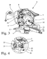
- Fig. 3 shows the chop saw Fig. 1
- this has not reached its deepest sawing, in which the saw blade 10 enters the edge of the immersion slot 21 in the turntable 19 and boom 20 at the edge.
- the ring gear of the saw blade 10 is slightly above the workpiece support surface 2. This is effected by a manually activatable stop element 22 of a total realized groove depth stop 23. This is activated in the trajectory of a counter-attack 24 on the saw unit 5, which is in Fig. 4 detects, however, is located outside the trajectory of the counter-attack 24, which is in Fig. 2 recognizes.
- the stop element 22 is located on the left outside the movement path of the counter-stop 24.
- the groove depth stop 23 is arranged on the transverse axis 6.
- the stop element 22 of the groove depth stop 23 is activated by a displacement movement in the direction of the transverse axis 6 ( Fig. 4 ) and deactivated ( Fig. 2 ).
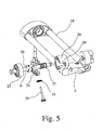
- Fig. 5 indicates that here the transverse axis 6 of the holder 4 is physically present and that the stop element 22 of the groove depth stop 23 is mounted linearly displaceable on the physically present transverse axis 6.
- the stop element 22 is coupled with a side seated on the holder 4 actuator 25.
- this actuator 25 is designed as a compact operating knob, possibly with a knurling.
- the displacement movement of the stop element 22 is driven by the rotation of the actuating element 25 about the transverse axis 6.
- An operator can easily reach the left side of the saw unit 5 grab the compact operating knob 25 and ergonomically useful forward, in Fig. 1 and 2 so clockwise, turn.
- the stop element 22 moves in Fig. 1 and 2 to the right into the activated position, then in 3 and 4 is shown.
- a helical wedge gear 26 is provided here, which is not designed to be self-locking. You can see that in Fig. 5 especially good. It is further provided that the actuating element 25 engages in the activated position of the stop element 22. This can be done directly or within the wedge gear 26.
- the construction with the wedge gear 26 has a particular advantage when the stop element 22 is biased by a spring 27 in the direction of the deactivated position. You can see that in Fig. 5 based on the compression spring, which is arranged in a chamber of the bearing 28 on the transverse axis 6.
- This bearing 28 has a lateral, extending in the direction of the transverse axis 6 opening 29, in which the laterally projecting arm, the Stop element 22 forms, in Fig. 5 from left to right and vice versa. Through the opening 29, the altitude of the stop element 22 is fixed. This can only move to the right or left in the opening 29.
- an adjustable stop buffer 30 This consists of a threaded rod with an end-side knurled nut, which is screwed into a threaded bore in the stop element 22.
- a lock nut 31 also designed as a knurled nut, allows the stop buffer 30 to be fixed in the desired position for the intended groove depth.
- the inventively realized groove depth stop is convenient and ergonomically comfortable to operate. He is not prone to error, stable and accidental operation of the groove function is hardly possible because the stop member 22 wedged in a manually made displacement on the physically existing transverse axis 6. The operator is thus prompted intuitively to a correct operation.
Landscapes
- Engineering & Computer Science (AREA)
- Mechanical Engineering (AREA)
- Life Sciences & Earth Sciences (AREA)
- Wood Science & Technology (AREA)
- Forests & Forestry (AREA)
- Sawing (AREA)
Description
- Die Erfindung betrifft eine Kappsäge mit den Merkmalen des Oberbegriffs von Anspruch 1. Eine solche Säge ist aus
EP 1 510 307 A1 bekannt. - Kappsägen der in Rede stehenden Art sind seit Jahrzehnten bekannt (
EP-A-1 557 231 ). Sie werden zur Bearbeitung aller Arten von Werkstoffen eingesetzt. Ein besonderes Anwendungsfeld finden Kappsägen bei der Holzbearbeitung. Sie sind aber auch für die Kunststoffbearbeitung und die Metallbearbeitung zu finden. - Eine typische Kappsäge hat ein um eine Querachse schwenkbar angebrachtes Sägeaggregat, dessen Sägeblatt aus einer angehobenen Ruhestellung in eine abgesenkte Sägestellung und umgekehrt schwenkbar ist. Mit dieser Bewegung des Sägeblattes kann ein auf einer Werkstückauflagefläche eines Trägers befindliches Werkstück abgeschnitten - gekappt - werden.
- Kappsägen sind aber nicht nur mit um eine Querachse schwenkbar angebrachtem Sägeaggregat bekannt, sondern auch mit einem in Längsrichtung über die Werkstückauflagefläche ziehbaren Sägeaggregat als sog. Radialarmsägen.
- Das Sägeaggregat einer Kappsäge ist normalerweise in Richtung der Ruhestellung vorgespannt. Das geschieht meist durch eine Federanordnung, bei älteren Konstruktionen auch noch durch ein Gegengewicht. Entgegen der Vorspannkraft wird das Sägeaggregat an einem Betätigungshandgriff angefaßt und zum Ausführen des Sägeschnittes nach unten geschwenkt bis das auf der Werkstückauflagefläche befindliche Werkstück vollständig durchtrennt ist. Dabei tritt ein kleines Teilstück des Sägeblattes des Sägeaggregates randseitig in einen Eintauchschlitz in der Werkstückauflagefläche ein.
- Die bekannte Kappsäge, von der die Erfindung ausgeht (
DE-U-203 13 885 ), ist eine Kapp-, Gehrungs- und Zugsäge, mit der Kappschnitte, Gehrungsschnitte und Schifterschnitte (Doppel-Gehrungs-Schnitte) ausgeführt werden können. Wegen der außerdem wie bei einer Radialarmsäge realisierten Zugfunktion können die ausgeführten Schnitte länger sein als es der wirksame Schnitthalbmesser des Sägeblattes vorgibt. - Bei der bekannten Kappsäge ist das Sägeaggregat mittels einer Halterung am Träger angebracht. Bei der Kappfunktion wird das Sägeaggregat um eine Querachse aus der angehobenen Ruhestellung in die abgesenkte Sägestellung und umgekehrt geschwenkt.
- Da die zuvor erläuterte bekannte Kappsäge auch eine Zugfunktion hat, kann man in einem auf der Werkstückauflage befindlichen Werkstück nicht nur einen Kappschnitt ausführen, sondern auch eine Nut anbringen. Dabei wird das Werkstück nicht vollständig durchtrennt, sondern das Sägeaggregat wird in einer nicht ganz abgesenkten Stellung fixiert und dann linear durch das Werkstück gezogen.
- Um bei dem zuvor erläuterten Nuten eines Werkstückes die Tiefe der Nut vorgeben zu können, hat eine solche Kappsäge mit Zugfunktion einen Nuttiefenanschlag, der ein manuell aktivierbares Anschlagelement aufweist. In aktivierter Position befindet sich das Anschlagelement in der Bewegungsbahn eines Gegenanschlags am Sägeaggregat. Ist das Anschlagelement deaktiviert, so befindet es sich außerhalb der Bewegungsbahn des Gegenanschlags und das Sägeaggregat kann bis in seine tiefste Stellung, die vollständige Sägestellung, nach unten geschwenkt werden.
- Bei der bekannten Kappsäge, von der die Erfindung ausgeht, ist das Anschlagelement an der Halterung um eine im wesentlichen senkrecht zur Werkstückauflagefläche verlaufende Achse schwenkbar angeordnet. Zum Aktivieren wird es seitlich in die Bewegungsbahn des Gegenanschlags am Sägeaggregat eingeschwenkt. Wird es nicht benötigt, so klappt man es in seine deaktivierte Stellung zurück. Am Anschlagelement selbst befindet sich wiederum ein verstellbarer Anschlagpuffer, so daß die Nuttiefe durch Verstellen des Anschlagpuffers unterschiedlich gewählt werden kann.
- Die Konstruktion des Nuttiefenanschlags bei der bekannten Kappsäge wirkt klapprig. Außerdem kann es passieren, daß das Anschlagelement versehentlich in die Bahn des Gegenanschlags geklappt wird oder sich auch nur halb in dieser Bewegungsbahn befindet. Das kann zu unangenehmen Fehlern beim Nuten von Werkstücken führen.
- Der Lehre liegt daher das Problem zugrunde, die bekannte Kappsäge mit einem optimierten Nuttiefenanschlag zu versehen.
- Die zuvor aufgezeigte Problemstellung ist bei einer Kappsäge mit den Merkmalen des Oberbegriffs von Anspruch 1 durch die Merkmale des kennzeichnenden Teils von Anspruch 1 gelöst.
- Dadurch, daß der Nuttiefenanschlag an der Querachse selbst angeordnet ist, kann das Anschlagelement durch eine Verschiebebewegung in Richtung der Querachse verlagert werden. Das Anschlagelement wird also nicht mehr hin- und hergeklappt, es wird durch eine lineare Verschiebung in Richtung der Querachse aktiviert und deaktiviert. Das ist eine raffinierte Betätigungsart. Durch geschickte konstruktive Ausgestaltung dieser Verschiebebetätigung kann ein versehentliches Betätigen der Nutfunktion nahezu sicher unterbunden werden.
- Bevorzugte Ausgestaltungen und Weiterbildungen der erfindungsgemäßen Lehre sind Gegenstand der Unteransprüche.
- Ist die Querachse körperlich vorhanden, so kann man vorsehen, daß das Anschlagelement auf der körperlich vorhandenen Querachse selbst linear verschiebbar gelagert ist. Die Querachse kann seitlich einfach etwas verlängert werden oder es wird in einem Lager eine entsprechende Ausnehmung vorgesehen.
- Von besonderer Bedeutung ist dabei eine Konstruktion, bei der vorgesehen ist, daß das Anschlagelement mit einem seitlich an der Halterung sitzenden Betätigungselement, insbesondere einem Betätigungsknauf, gekoppelt ist und die Verschiebebewegung des Anschlagelements durch eine Drehbewegung des Betätigungselements um die Querachse antreibbar ist. Durch eine komfortable, kompakte Drehbewegung am Betätigungselement, vorzugsweise bis zu einem Einrasten des Betätigungselementes sobald das Anschlagelement seine aktivierte Stellung erreicht hat, ergibt sich ein vorzüglicher Bedienungskomfort.
- Von besonderer Bedeutung ist ferner eine Konstruktion, bei der vorgesehen ist, daß die Kopplung zwischen dem Betätigungselement und dem Anschlagelement als schraubenlinienförmiges, nicht selbsthemmendes Keilgetriebe ausgeführt ist. Ein solches nichtselbsthemmendes Keilgetriebe ist insbesondere zweckmäßig einsetzbar in Verbindung mit einer Feder, durch die das Anschlagelement in Richtung seiner deaktivierten Stellung vorgespannt ist. Durch eine Drehbewegung des Betätigungselementes in einer Drehrichtung kann das Anschlagelement in seine aktivierte Stellung gebracht werden. Dabei wird die Feder gespannt. Rastet das Betätigungselement direkt oder an dem schraubenlinienförmigen Keilgetriebe ein, so ist dieser Zustand vorübergehend fixiert. Wird das Betätigungselement in der Gegenrichtung betätigt, so rastet es aus und die Feder drückt das Anschlagelement unter Rückdrehung des Betätigungselementes in seine Ausgangsstellung in die deaktivierte Stellung zurück.
- Im folgenden wird nun die Erfindung anhand einer lediglich ein Ausführungsbeispiel darstellenden Zeichnung näher erläutert. In der Zeichnung zeigt
- Fig. 1
- in perspektivischer Darstellung ein Ausführungsbeispiel einer erfindungsgemäßen Kappsäge mit dem Sägeaggregat in Ruhestellung,
- Fig. 2
- einen Ausschnitt aus
Fig. 1 mit dem Nuttiefenanschlag in vergrößerter Darstellung, - Fig. 3
- in einer
Fig. 1 entsprechenden Darstellung die Kappsäge mit dem Sägeaggregat in Nutstellung, - Fig. 4
- in einem
Fig. 2 entsprechenden Ausschnitt den aktivierten Nuttiefenanschlag und - Fig. 5
- in einer Sprengdarstellung die für die Konstruktion des Nuttiefenanschlags wesentlichen Teile der erfindungsgemäßen Kappsäge.
-
Fig. 1 zeigt eine Kappsäge, genauer gesagt eine Kapp-, Gehrungssäge- und Zugsäge. - Die in
Fig. 1 dargestellte Kappsäge weist zunächst einen Träger 1 auf, der eine Werkstückauflagefläche 2 bildet. Das rückwärtige Ende der Werkstückauflagefläche 2 bildet hier eine Anschlagschiene 3, an der ein Werkstück, beispielsweise eine Holzleiste, angelegt werden kann. Am Träger 1 ist eine Halterung 4 angebracht, die rückwärtig hinter der Werkstückauflagefläche 2 liegt. - An der Halterung 4 oberhalb des Trägers 1 angebracht ist ein Sägeaggregat 5. Dieses ist im dargestellten und bevorzugten Ausführungsbeispiel um eine Querachse 6 schwenkbar und befindet sich oberhalb der Werkstückauflagefläche 2.
- Bei der dargestellten Kappsäge wird das Sägeaggregat 5 um die Querachse 6 aus einer angehobenen Ruhestellung, die in
Fig. 1 zu erkennen ist, in eine abgesenkte Sägestellung, die hier nicht dargestellt ist, und umgekehrt geschwenkt. Das Sägeaggregat 5 ist dabei in Richtung der Ruhestellung, also nach oben hin vorgespannt, insbesondere durch eine Feder. Dadurch kehrt das Sägeaggregat 5, wenn man es losläßt, von selbst wieder in die angehobene Ruhestellung zurück. - Das Sägeaggregat 5 weist auf,
- einen Betätigungshandgriff 7,
- einen Antriebsmotor 8
- ein vom Antriebsmotor 8 angetriebenes, auf einer Welle 9 gelagertes Sägeblatt 10,
- eine das Sägeblatt 10 von oben her etwa über die Hälfte abdeckende feststehende Schutzhaube 11,
- eine Pendelschutzhaube 12, die in der in
Fig. 1 dargestellten Ruhestellung den unteren Teil des Zahnkranzes des Sägeblattes 10 abdeckt, - einen Absaugstutzen 13 einer Staubfangvorrichtung und
- eine im Bereich zwischen der Halterung 4 und der Welle 9 unterhalb der feststehenden Schutzhaube 11 angeordnete bewegliche Staubfanghaube 14.
- Letzteres ist eine besondere Ausstattung der Kappsäge, die nicht immer verwirklicht sein muß, aber in besonders zweckmäßiger Weise hier verwirklicht ist.
- Die dargestellte Kappsäge hat neben der zuvor bereits beschriebenen Kappfunktion eine Gehrungsfunktion. Es handelt sich also zunächst bereits um eine Kappund Gehrungssäge.
- Die dargestellte und bevorzugte Kappsäge hat jedoch nicht nur eine Kappfunktion und eine Gehrungsfunktion, sie hat auch eine Zugfunktion. Das Sägeaggregat 5 ist an der Halterung 4 nicht nur mittels der Querachse 6 schwenkbar gelagert, sondern zusätzlich auch noch mittels einer in Sägerichtung verlaufenden Zuführung 18 aus zwei parallel zueinander verlaufenden Zugstangen 18 a,b verschiebbar gelagert. Mit dieser Zugfunktion läßt sich der vom Sägeaggregat 5 ausführbare Sägeschnitt verlängern und sie ist Voraussetzung für eine Nutfunktion der Kappsäge.
- Das dargestellte und bevorzugte Ausführungsbeispiel zeigt am Träger 1 einen eingelassenen Drehteller 19 mit einem nach vorne vorspringenden Auslegerarm 20 und mit einem Eintauchschlitz 21, in den in Sägestellung der Rand des Sägeblattes 10 eintritt. Die Länge des Eintauchschlitzes 21 ist wesentlich größer als es für den Durchmesser des Sägeblattes 10 erforderlich ist. Das liegt an der zuvor erläuterten Zuführung 18, die eben auch ein Ziehen des Sägeblattes 10 durch das Werkstück über einen bestimmten Weg erlaubt.
- Bei der vorliegenden Erfindung geht es um die Möglichkeit, mit einer Kappsäge der in Rede stehenden Art in einem Werkstück eine Nut bestimmter Tiefe anzubringen. Die Zuführung 18 erlaubt eine solche Nutfunktion.
-
Fig. 3 zeigt die Kappsäge ausFig. 1 mit nach unten abgesenktem Sägeaggregat 5. Dieses hat jedoch nicht seine tiefste Sägestellung erreicht, in der das Sägeblatt 10 randseitig in den Eintauchschlitz 21 im Drehteller 19 und Auslegerarm 20 eintritt. Man sieht, daß der Zahnkranz des Sägeblattes 10 etwas oberhalb der Werkstückauflagefläche 2 liegt. Dies wird bewirkt durch ein manuell aktivierbares Anschlagelement 22 eines insgesamt realisierten Nuttiefenanschlags 23. Dieses liegt aktiviert in der Bewegungsbahn eines Gegenanschlags 24 am Sägeaggregat 5, was man inFig. 4 erkennt, befindet sich hingegen deaktiviert außerhalb der Bewegungsbahn des Gegenanschlags 24, was man inFig. 2 erkennt. InFig. 2 liegt das Anschlagelement 22 nämlich links außerhalb der Bewegungsbahn des Gegenanschlags 24. InFig. 4 ist es nach rechts gerückt und der Gegenanschlag 24 trifft beim Herunterschwenken des Sägeaggregates 5 um die Querachse 6 auf das Anschlagelement 22. Dadurch wird das weitere Herabschwenken des Sägeaggregates 5 gestoppt. Hält man das Sägeaggregat 5 in dieser Stellung fest und zieht es dann an der Zuführung 18 nach vorn, so kann man in dem auf der Werkstückauflagefläche 2 festgehaltenen Werkstück eine Längsnut bestimmter Tiefe einbringen. - Aus einem Vergleich von
Fig. 2 undFig. 4 sowie mit Blick aufFig. 5 erkennt man, daß erfindungsgemäß der Nuttiefenanschlag 23 an der Querachse 6 angeordnet ist. Das Anschlagelement 22 des Nuttiefenanschlags 23 wird durch eine Verschiebebewegung in Richtung der Querachse 6 aktiviert (Fig. 4 ) und deaktiviert (Fig. 2 ). -
Fig. 5 läßt erkennen, daß hier die Querachse 6 der Halterung 4 körperlich vorhanden ist und daß das Anschlagelement 22 des Nuttiefenanschlags 23 auf der körperlich vorhandenen Querachse 6 linear verschiebbar gelagert ist. Man erkennt, daß im dargestellten Ausführungsbeispiel das Anschlagelement 22 mit einem seitlich an der Halterung 4 sitzenden Betätigungselement 25 gekuppelt ist. Im dargestellten und bevorzugten Ausführungsbeispiel ist dieses Betätigungselement 25 als kompakter Betätigungsknauf, ggf. mit einer Rändelung, ausgeführt. Die Verschiebebewegung des Anschlagelements 22 wird durch die Drehung des Betätigungselements 25 um die Querachse 6 angetrieben. Eine Bedienungsperson kann ganz einfach links an die Seite des Sägeaggregates 5 greifen, den kompakten Betätigungsknauf 25 erfassen und ihn ergonomisch sinnvoll nach vorn, inFig. 1 und 2 also im Uhrzeigersinn, drehen. Dadurch verschiebt sich das Anschlagelement 22 inFig. 1 und 2 nach rechts in die aktivierte Stellung, die dann inFig. 3 und 4 dargestellt ist. - Zur Übertragung der Drehbewegung des Betätigungselements 25 auf das Anschlagelement 22 ist hier ein schraubenlinienförmiges Keilgetriebe 26 vorgesehen, das nicht selbsthemmend ausgeführt ist. Man erkennt das in
Fig. 5 besonders gut. Ferner ist vorgesehen, daß das Betätigungselement 25 in der aktivierten Stellung des Anschlagelementes 22 einrastet. Das kann unmittelbar geschehen oder innerhalb des Keilgetriebes 26. Die Konstruktion mit dem Keilgetriebe 26 hat einen besonderen Vorteil dann, wenn das Anschlagelement 22 durch eine Feder 27 in Richtung der deaktivierten Stellung vorgespannt ist. Man erkennt das inFig. 5 anhand der Druckfeder, die in einer Kammer des Lagers 28 an der Querachse 6 angeordnet ist. Dieses Lager 28 hat eine seitliche, in Richtung der Querachse 6 verlaufende Öffnung 29, in der der seitlich vorspringende Arm, der das Anschlagelement 22 bildet, inFig. 5 von links nach rechts und umgekehrt verschoben werden kann. Durch die Öffnung 29 wird die Höhenlage des Anschlagelementes 22 fest vorgegeben. Dieses kann sich nur nach rechts oder links in der Öffnung 29 verschieben. - Die Rückverschiebung des Anschlagelementes 22 aus der aktivierten in die deaktivierte Stellung erfolgt durch die Feder 27. Da das Keilgetriebe 26 nicht selbsthemmend ist, wird bei dieser Bewegung des Anschlagelements 22 gleichzeitig das Betätigungselement 25 zurück in seine Ausgangsstellung gedreht. Zuvor muß allerdings die Einrastung des Betätigungselements 25 gelöst worden sein.
- Am Anschlagelement 22 erkennt man ferner in
Fig. 2 undFig. 4 einen verstellbaren Anschlagpuffer 30. Dieser besteht aus einer Gewindestange mit einer endseitigen Rändelmutter, die in eine Gewindebohrung im Anschlagelement 22 eingeschraubt wird. Eine Kontermutter 31, ebenfalls ausgeführt als Rändelmutter, erlaubt es, den Anschlagpuffer 30 in der gewünschten Position für die beabsichtigte Nuttiefe zu fixieren. - Der erfindungsgemäß verwirklichte Nuttiefenanschlag ist zweckmäßig und ergonomisch angenehm zu betätigen. Er ist nicht fehleranfällig, stabil und ein versehentliches Betätigen der Nutfunktion ist kaum möglich, da sich das Anschlagelement 22 bei einem von Hand vorgenommenen Verschieben auf der körperlich vorhandenen Querachse 6 verkeilt. Der Bediener wird also intuitiv zu einer vorschriftsmäßigen Bedienung veranlaßt.
Claims (7)
- Kappsäge mit
einem Träger (1), der eine Werkstückauflagefläche (2) bildet,
einer am Träger (1) angebrachten Halterung (4) und
einem an der Halterung (4) oberhalb des Trägers (1) um eine Querachse (6) schwenkbar angebrachten Sägeaggregat (5),
wobei das Sägeaggregat (5) um die Querachse (6) aus einer angehobenen Ruhestellung in eine abgesenkte Sägestellung und umgekehrt schwenkbar ist, und wobei das Sägeaggregat (5) an der Halterung (4) mittels einer in Sägerichtung verlaufenden Zugführung (18) in Sägerichtung verschiebbar gelagert ist,
wobei die tiefste Position des Sägeaggregates (5) in Sägestellung durch einen festen Anschlag definiert ist und eine etwas höher liegende Position des Sägeaggregates (5) durch ein manuell aktivierbares Anschlagelement (22) eines Nuttiefenanschlags (23) definiert ist, das aktiviert in der Bewegungsbahn und deaktiviert außerhalb der Bewegungsbahn eines Gegenanschlags (24) am Sägeaggregat (5) liegt,
dadurch gekennzeichnet,
daß der Nuttiefenanschlag (23) an der Querachse (6) angeordnet ist und das Anschlagelement (22) des Nuttiefenanschlags (23) durch eine Verschiebebewegung in Richtung der Querachse (6) aktivierbar und deaktivierbar ist. - Kappsäge nach Anspruch 1, dadurch gekennzeichnet,
daß das Anschlagelement (22) auf der körperlich vorhandenen Querachse (6) linear verschiebbar gelagert ist. - Kappsäge nach Anspruch 1 oder 2, dadurch gekennzeichnet,
daß das Anschlagelement (22) mit einem seitlich an der Halterung (4) sitzenden Betätigungselement (25), insbesondere einem Betätigungsknauf, gekoppelt ist und die Verschiebebewegung des Anschlagelements (22) durch eine Drehbewegung des Betätigungselements (25) um die Querachse (6) antreibbar ist. - Kappsäge nach Anspruch 3, dadurch gekennzeichnet,
daß die Kopplung zwischen dem Betätigungselement (25) und dem Anschlagelement (22) als schraubenlinienförmiges, nicht selbsthemmendes Keilgetriebe (26) ausgeführt ist. - Kappsäge nach Anspruch 3 oder 4, dadurch gekennzeichnet,
daß das Betätigungselement (25) in der aktivierten Stellung des Anschlagelements (22) einrastet. - Kappsäge nach einem der Ansprüche 1 bis 5, dadurch gekennzeichnet,
daß das Anschlagelement (22) durch eine Feder (27) in Richtung seiner deaktivierten Stellung vorgespannt ist. - Kappsäge nach einem der Ansprüche 1 bis 6, dadurch gekennzeichnet,
daß das Anschlagelement (22) selbst einen verstellbaren Anschlagpuffer (30) aufweist.
Applications Claiming Priority (2)
| Application Number | Priority Date | Filing Date | Title |
|---|---|---|---|
| DE202008001742U DE202008001742U1 (de) | 2008-02-07 | 2008-02-07 | Kappsäge mit Nuttiefenanschlag |
| PCT/EP2008/009394 WO2009097876A1 (de) | 2008-02-07 | 2008-11-07 | Kappsäge mit nuttiefenanschlag |
Publications (2)
| Publication Number | Publication Date |
|---|---|
| EP2249989A1 EP2249989A1 (de) | 2010-11-17 |
| EP2249989B1 true EP2249989B1 (de) | 2015-07-29 |
Family
ID=40282340
Family Applications (1)
| Application Number | Title | Priority Date | Filing Date |
|---|---|---|---|
| EP08872201.2A Active EP2249989B1 (de) | 2008-02-07 | 2008-11-07 | Kappsäge mit nuttiefenanschlag |
Country Status (3)
| Country | Link |
|---|---|
| EP (1) | EP2249989B1 (de) |
| DE (1) | DE202008001742U1 (de) |
| WO (1) | WO2009097876A1 (de) |
Families Citing this family (2)
| Publication number | Priority date | Publication date | Assignee | Title |
|---|---|---|---|---|
| CN108724286A (zh) * | 2018-04-30 | 2018-11-02 | 中山市翔实机械设备有限公司 | 一种方便携带的切割机 |
| CN113319372B (zh) * | 2021-06-28 | 2022-08-05 | 汪永生 | 一种铝型材精密切割设备及切割方法 |
Family Cites Families (8)
| Publication number | Priority date | Publication date | Assignee | Title |
|---|---|---|---|---|
| JP2784424B2 (ja) * | 1990-11-28 | 1998-08-06 | 日立工機株式会社 | 卓上切断機の下限位置設定装置 |
| DE4442950A1 (de) * | 1994-12-02 | 1996-06-05 | Otto Bergler | Kombinierte Tisch- Gehrungskappsäge und Auslegersäge mit Doppelanschlag zur Tauchtiefenbegrenzung beim Kapp- und Ausleger sägen |
| JP3490259B2 (ja) * | 1997-07-22 | 2004-01-26 | 株式会社マキタ | 丸鋸盤 |
| JPH1134002A (ja) * | 1997-07-23 | 1999-02-09 | Makita Corp | 丸鋸盤の下限ストッパ装置 |
| TW569908U (en) | 2002-09-26 | 2004-01-01 | P & F Brother Ind Corp | Apparatus for adjusting and aligning slant cutting angle of cutting machine |
| JP4254429B2 (ja) * | 2003-08-28 | 2009-04-15 | 日立工機株式会社 | 卓上スライド切断機 |
| DE202004000983U1 (de) | 2004-01-22 | 2005-03-10 | Metabowerke Gmbh | Kappsäge mit Staubfangvorrichtung |
| DE202006012341U1 (de) * | 2006-08-10 | 2006-10-19 | Metabowerke Gmbh | Kappsäge mit Längssägefunktion |
-
2008
- 2008-02-07 DE DE202008001742U patent/DE202008001742U1/de not_active Expired - Lifetime
- 2008-11-07 WO PCT/EP2008/009394 patent/WO2009097876A1/de not_active Ceased
- 2008-11-07 EP EP08872201.2A patent/EP2249989B1/de active Active
Also Published As
| Publication number | Publication date |
|---|---|
| DE202008001742U1 (de) | 2009-07-09 |
| WO2009097876A1 (de) | 2009-08-13 |
| EP2249989A1 (de) | 2010-11-17 |
Similar Documents
| Publication | Publication Date | Title |
|---|---|---|
| EP1557231B1 (de) | Kappsäge mit Staubfangvorrichtung | |
| DE69405655T2 (de) | Kappsäge mit Parallelogramkonstruktion | |
| EP0598248A1 (de) | Elektromotorische Handkreissäge | |
| EP1418018B1 (de) | Führungsschiene für Handwerkzeugmaschinen mit zugeordnetem Anschlagstück | |
| EP2249989B1 (de) | Kappsäge mit nuttiefenanschlag | |
| EP2241396B1 (de) | Werkzeugmaschine, insbesondere Kappsäge. | |
| EP2250005B1 (de) | Kappsäge mit neigungsverstellung | |
| EP1454695A2 (de) | Durchlaufschere | |
| EP2158991B1 (de) | Kappsäge mit Zugfunktion | |
| EP2199000B1 (de) | Werkzeugmaschine, insbesondere Kapp- und Gehrungssäge | |
| DE19635527A1 (de) | Tauchsäge | |
| DE202008001743U1 (de) | Kappsäge mit einer Staubabsaugung und/oder einer Verkleidung | |
| EP2250006B1 (de) | Kappsäge mit neigungsverstellung | |
| EP2241422B1 (de) | Kappsäge mit Neigungsverstellung | |
| DE202007006291U1 (de) | Sägeeinrichtung mit Verstellhalterung für das Sägeaggregat | |
| DE4010456C2 (de) | ||
| EP2198999B1 (de) | Werkzeugmaschine, insbesondere Kapp- und Gehrungssäge | |
| EP2277674B1 (de) | Werkzeugmaschine, insbesondere Sägeeinrichtung | |
| DE1528003A1 (de) | Vorrichtung zum Bearbeiten von plattenfoermigen Werkstuecken | |
| EP2216148B1 (de) | Kappsäge | |
| EP2231372B1 (de) | Kappsäge mit einer transportsicherung | |
| DE202006012341U1 (de) | Kappsäge mit Längssägefunktion | |
| EP2142329B1 (de) | Sägeeinrichtung mit verstellhalterung für das sägeaggregat | |
| EP2186588B1 (de) | Kapp- und Gehrungssäge | |
| DE202009005543U1 (de) | Kappsäge mit einem Sägengehäuse |
Legal Events
| Date | Code | Title | Description |
|---|---|---|---|
| PUAI | Public reference made under article 153(3) epc to a published international application that has entered the european phase |
Free format text: ORIGINAL CODE: 0009012 |
|
| 17P | Request for examination filed |
Effective date: 20090902 |
|
| AK | Designated contracting states |
Kind code of ref document: A1 Designated state(s): AT BE BG CH CY CZ DE DK EE ES FI FR GB GR HR HU IE IS IT LI LT LU LV MC MT NL NO PL PT RO SE SI SK TR |
|
| AX | Request for extension of the european patent |
Extension state: AL BA MK RS |
|
| DAX | Request for extension of the european patent (deleted) | ||
| GRAP | Despatch of communication of intention to grant a patent |
Free format text: ORIGINAL CODE: EPIDOSNIGR1 |
|
| INTG | Intention to grant announced |
Effective date: 20150317 |
|
| GRAS | Grant fee paid |
Free format text: ORIGINAL CODE: EPIDOSNIGR3 |
|
| GRAA | (expected) grant |
Free format text: ORIGINAL CODE: 0009210 |
|
| AK | Designated contracting states |
Kind code of ref document: B1 Designated state(s): AT BE BG CH CY CZ DE DK EE ES FI FR GB GR HR HU IE IS IT LI LT LU LV MC MT NL NO PL PT RO SE SI SK TR |
|
| REG | Reference to a national code |
Ref country code: GB Ref legal event code: FG4D Free format text: NOT ENGLISH |
|
| REG | Reference to a national code |
Ref country code: CH Ref legal event code: EP |
|
| REG | Reference to a national code |
Ref country code: AT Ref legal event code: REF Ref document number: 738876 Country of ref document: AT Kind code of ref document: T Effective date: 20150815 |
|
| REG | Reference to a national code |
Ref country code: IE Ref legal event code: FG4D Free format text: LANGUAGE OF EP DOCUMENT: GERMAN |
|
| REG | Reference to a national code |
Ref country code: DE Ref legal event code: R096 Ref document number: 502008013216 Country of ref document: DE |
|
| REG | Reference to a national code |
Ref country code: FR Ref legal event code: PLFP Year of fee payment: 8 |
|
| REG | Reference to a national code |
Ref country code: LT Ref legal event code: MG4D |
|
| REG | Reference to a national code |
Ref country code: NL Ref legal event code: MP Effective date: 20150729 |
|
| PG25 | Lapsed in a contracting state [announced via postgrant information from national office to epo] |
Ref country code: FI Free format text: LAPSE BECAUSE OF FAILURE TO SUBMIT A TRANSLATION OF THE DESCRIPTION OR TO PAY THE FEE WITHIN THE PRESCRIBED TIME-LIMIT Effective date: 20150729 Ref country code: LT Free format text: LAPSE BECAUSE OF FAILURE TO SUBMIT A TRANSLATION OF THE DESCRIPTION OR TO PAY THE FEE WITHIN THE PRESCRIBED TIME-LIMIT Effective date: 20150729 Ref country code: GR Free format text: LAPSE BECAUSE OF FAILURE TO SUBMIT A TRANSLATION OF THE DESCRIPTION OR TO PAY THE FEE WITHIN THE PRESCRIBED TIME-LIMIT Effective date: 20151030 Ref country code: LV Free format text: LAPSE BECAUSE OF FAILURE TO SUBMIT A TRANSLATION OF THE DESCRIPTION OR TO PAY THE FEE WITHIN THE PRESCRIBED TIME-LIMIT Effective date: 20150729 Ref country code: NO Free format text: LAPSE BECAUSE OF FAILURE TO SUBMIT A TRANSLATION OF THE DESCRIPTION OR TO PAY THE FEE WITHIN THE PRESCRIBED TIME-LIMIT Effective date: 20151029 |
|
| PG25 | Lapsed in a contracting state [announced via postgrant information from national office to epo] |
Ref country code: PT Free format text: LAPSE BECAUSE OF FAILURE TO SUBMIT A TRANSLATION OF THE DESCRIPTION OR TO PAY THE FEE WITHIN THE PRESCRIBED TIME-LIMIT Effective date: 20151130 Ref country code: PL Free format text: LAPSE BECAUSE OF FAILURE TO SUBMIT A TRANSLATION OF THE DESCRIPTION OR TO PAY THE FEE WITHIN THE PRESCRIBED TIME-LIMIT Effective date: 20150729 Ref country code: HR Free format text: LAPSE BECAUSE OF FAILURE TO SUBMIT A TRANSLATION OF THE DESCRIPTION OR TO PAY THE FEE WITHIN THE PRESCRIBED TIME-LIMIT Effective date: 20150729 Ref country code: ES Free format text: LAPSE BECAUSE OF FAILURE TO SUBMIT A TRANSLATION OF THE DESCRIPTION OR TO PAY THE FEE WITHIN THE PRESCRIBED TIME-LIMIT Effective date: 20150729 Ref country code: IS Free format text: LAPSE BECAUSE OF FAILURE TO SUBMIT A TRANSLATION OF THE DESCRIPTION OR TO PAY THE FEE WITHIN THE PRESCRIBED TIME-LIMIT Effective date: 20151129 Ref country code: SE Free format text: LAPSE BECAUSE OF FAILURE TO SUBMIT A TRANSLATION OF THE DESCRIPTION OR TO PAY THE FEE WITHIN THE PRESCRIBED TIME-LIMIT Effective date: 20150729 |
|
| PG25 | Lapsed in a contracting state [announced via postgrant information from national office to epo] |
Ref country code: NL Free format text: LAPSE BECAUSE OF FAILURE TO SUBMIT A TRANSLATION OF THE DESCRIPTION OR TO PAY THE FEE WITHIN THE PRESCRIBED TIME-LIMIT Effective date: 20150729 |
|
| PG25 | Lapsed in a contracting state [announced via postgrant information from national office to epo] |
Ref country code: EE Free format text: LAPSE BECAUSE OF FAILURE TO SUBMIT A TRANSLATION OF THE DESCRIPTION OR TO PAY THE FEE WITHIN THE PRESCRIBED TIME-LIMIT Effective date: 20150729 Ref country code: SK Free format text: LAPSE BECAUSE OF FAILURE TO SUBMIT A TRANSLATION OF THE DESCRIPTION OR TO PAY THE FEE WITHIN THE PRESCRIBED TIME-LIMIT Effective date: 20150729 Ref country code: IT Free format text: LAPSE BECAUSE OF FAILURE TO SUBMIT A TRANSLATION OF THE DESCRIPTION OR TO PAY THE FEE WITHIN THE PRESCRIBED TIME-LIMIT Effective date: 20150729 Ref country code: DK Free format text: LAPSE BECAUSE OF FAILURE TO SUBMIT A TRANSLATION OF THE DESCRIPTION OR TO PAY THE FEE WITHIN THE PRESCRIBED TIME-LIMIT Effective date: 20150729 Ref country code: CZ Free format text: LAPSE BECAUSE OF FAILURE TO SUBMIT A TRANSLATION OF THE DESCRIPTION OR TO PAY THE FEE WITHIN THE PRESCRIBED TIME-LIMIT Effective date: 20150729 |
|
| REG | Reference to a national code |
Ref country code: DE Ref legal event code: R097 Ref document number: 502008013216 Country of ref document: DE |
|
| PG25 | Lapsed in a contracting state [announced via postgrant information from national office to epo] |
Ref country code: RO Free format text: LAPSE BECAUSE OF FAILURE TO SUBMIT A TRANSLATION OF THE DESCRIPTION OR TO PAY THE FEE WITHIN THE PRESCRIBED TIME-LIMIT Effective date: 20150729 |
|
| PLBE | No opposition filed within time limit |
Free format text: ORIGINAL CODE: 0009261 |
|
| STAA | Information on the status of an ep patent application or granted ep patent |
Free format text: STATUS: NO OPPOSITION FILED WITHIN TIME LIMIT |
|
| PG25 | Lapsed in a contracting state [announced via postgrant information from national office to epo] |
Ref country code: LU Free format text: LAPSE BECAUSE OF FAILURE TO SUBMIT A TRANSLATION OF THE DESCRIPTION OR TO PAY THE FEE WITHIN THE PRESCRIBED TIME-LIMIT Effective date: 20151107 Ref country code: MC Free format text: LAPSE BECAUSE OF FAILURE TO SUBMIT A TRANSLATION OF THE DESCRIPTION OR TO PAY THE FEE WITHIN THE PRESCRIBED TIME-LIMIT Effective date: 20150729 |
|
| REG | Reference to a national code |
Ref country code: CH Ref legal event code: PL |
|
| 26N | No opposition filed |
Effective date: 20160502 |
|
| PG25 | Lapsed in a contracting state [announced via postgrant information from national office to epo] |
Ref country code: LI Free format text: LAPSE BECAUSE OF NON-PAYMENT OF DUE FEES Effective date: 20151130 Ref country code: CH Free format text: LAPSE BECAUSE OF NON-PAYMENT OF DUE FEES Effective date: 20151130 |
|
| REG | Reference to a national code |
Ref country code: IE Ref legal event code: MM4A |
|
| PG25 | Lapsed in a contracting state [announced via postgrant information from national office to epo] |
Ref country code: SI Free format text: LAPSE BECAUSE OF FAILURE TO SUBMIT A TRANSLATION OF THE DESCRIPTION OR TO PAY THE FEE WITHIN THE PRESCRIBED TIME-LIMIT Effective date: 20150729 |
|
| PG25 | Lapsed in a contracting state [announced via postgrant information from national office to epo] |
Ref country code: IE Free format text: LAPSE BECAUSE OF NON-PAYMENT OF DUE FEES Effective date: 20151107 |
|
| REG | Reference to a national code |
Ref country code: FR Ref legal event code: PLFP Year of fee payment: 9 |
|
| REG | Reference to a national code |
Ref country code: AT Ref legal event code: MM01 Ref document number: 738876 Country of ref document: AT Kind code of ref document: T Effective date: 20151107 |
|
| PG25 | Lapsed in a contracting state [announced via postgrant information from national office to epo] |
Ref country code: AT Free format text: LAPSE BECAUSE OF NON-PAYMENT OF DUE FEES Effective date: 20151107 |
|
| PG25 | Lapsed in a contracting state [announced via postgrant information from national office to epo] |
Ref country code: HU Free format text: LAPSE BECAUSE OF FAILURE TO SUBMIT A TRANSLATION OF THE DESCRIPTION OR TO PAY THE FEE WITHIN THE PRESCRIBED TIME-LIMIT; INVALID AB INITIO Effective date: 20081107 Ref country code: BG Free format text: LAPSE BECAUSE OF FAILURE TO SUBMIT A TRANSLATION OF THE DESCRIPTION OR TO PAY THE FEE WITHIN THE PRESCRIBED TIME-LIMIT Effective date: 20150729 |
|
| PG25 | Lapsed in a contracting state [announced via postgrant information from national office to epo] |
Ref country code: CY Free format text: LAPSE BECAUSE OF FAILURE TO SUBMIT A TRANSLATION OF THE DESCRIPTION OR TO PAY THE FEE WITHIN THE PRESCRIBED TIME-LIMIT Effective date: 20150729 |
|
| PG25 | Lapsed in a contracting state [announced via postgrant information from national office to epo] |
Ref country code: BE Free format text: LAPSE BECAUSE OF NON-PAYMENT OF DUE FEES Effective date: 20151130 |
|
| PG25 | Lapsed in a contracting state [announced via postgrant information from national office to epo] |
Ref country code: MT Free format text: LAPSE BECAUSE OF FAILURE TO SUBMIT A TRANSLATION OF THE DESCRIPTION OR TO PAY THE FEE WITHIN THE PRESCRIBED TIME-LIMIT Effective date: 20150729 Ref country code: TR Free format text: LAPSE BECAUSE OF FAILURE TO SUBMIT A TRANSLATION OF THE DESCRIPTION OR TO PAY THE FEE WITHIN THE PRESCRIBED TIME-LIMIT Effective date: 20150729 |
|
| REG | Reference to a national code |
Ref country code: FR Ref legal event code: PLFP Year of fee payment: 10 |
|
| PGFP | Annual fee paid to national office [announced via postgrant information from national office to epo] |
Ref country code: FR Payment date: 20191121 Year of fee payment: 12 |
|
| PGFP | Annual fee paid to national office [announced via postgrant information from national office to epo] |
Ref country code: GB Payment date: 20191126 Year of fee payment: 12 |
|
| GBPC | Gb: european patent ceased through non-payment of renewal fee |
Effective date: 20201107 |
|
| PG25 | Lapsed in a contracting state [announced via postgrant information from national office to epo] |
Ref country code: FR Free format text: LAPSE BECAUSE OF NON-PAYMENT OF DUE FEES Effective date: 20201130 |
|
| PG25 | Lapsed in a contracting state [announced via postgrant information from national office to epo] |
Ref country code: GB Free format text: LAPSE BECAUSE OF NON-PAYMENT OF DUE FEES Effective date: 20201107 |
|
| PGFP | Annual fee paid to national office [announced via postgrant information from national office to epo] |
Ref country code: DE Payment date: 20251118 Year of fee payment: 18 |