EP4071771B1 - Ndfeb-permanentmagnet mit hoher koerzitivkraft und hohem widerstand und verfahren zur herstellung davon - Google Patents
Ndfeb-permanentmagnet mit hoher koerzitivkraft und hohem widerstand und verfahren zur herstellung davon Download PDFInfo
- Publication number
- EP4071771B1 EP4071771B1 EP21213079.3A EP21213079A EP4071771B1 EP 4071771 B1 EP4071771 B1 EP 4071771B1 EP 21213079 A EP21213079 A EP 21213079A EP 4071771 B1 EP4071771 B1 EP 4071771B1
- Authority
- EP
- European Patent Office
- Prior art keywords
- powder
- ndfeb
- magnet
- permanent magnet
- coercivity
- Prior art date
- Legal status (The legal status is an assumption and is not a legal conclusion. Google has not performed a legal analysis and makes no representation as to the accuracy of the status listed.)
- Active
Links
Images
Classifications
-
- H—ELECTRICITY
- H01—ELECTRIC ELEMENTS
- H01F—MAGNETS; INDUCTANCES; TRANSFORMERS; SELECTION OF MATERIALS FOR THEIR MAGNETIC PROPERTIES
- H01F41/00—Apparatus or processes specially adapted for manufacturing or assembling magnets, inductances or transformers; Apparatus or processes specially adapted for manufacturing materials characterised by their magnetic properties
- H01F41/02—Apparatus or processes specially adapted for manufacturing or assembling magnets, inductances or transformers; Apparatus or processes specially adapted for manufacturing materials characterised by their magnetic properties for manufacturing cores, coils, or magnets
- H01F41/0253—Apparatus or processes specially adapted for manufacturing or assembling magnets, inductances or transformers; Apparatus or processes specially adapted for manufacturing materials characterised by their magnetic properties for manufacturing cores, coils, or magnets for manufacturing permanent magnets
-
- H—ELECTRICITY
- H01—ELECTRIC ELEMENTS
- H01F—MAGNETS; INDUCTANCES; TRANSFORMERS; SELECTION OF MATERIALS FOR THEIR MAGNETIC PROPERTIES
- H01F1/00—Magnets or magnetic bodies characterised by the magnetic materials therefor; Selection of materials for their magnetic properties
- H01F1/01—Magnets or magnetic bodies characterised by the magnetic materials therefor; Selection of materials for their magnetic properties of inorganic materials
- H01F1/03—Magnets or magnetic bodies characterised by the magnetic materials therefor; Selection of materials for their magnetic properties of inorganic materials characterised by their coercivity
- H01F1/032—Magnets or magnetic bodies characterised by the magnetic materials therefor; Selection of materials for their magnetic properties of inorganic materials characterised by their coercivity of hard-magnetic materials
- H01F1/04—Magnets or magnetic bodies characterised by the magnetic materials therefor; Selection of materials for their magnetic properties of inorganic materials characterised by their coercivity of hard-magnetic materials metals or alloys
- H01F1/047—Alloys characterised by their composition
- H01F1/053—Alloys characterised by their composition containing rare earth metals
- H01F1/055—Alloys characterised by their composition containing rare earth metals and magnetic transition metals, e.g. SmCo5
- H01F1/057—Alloys characterised by their composition containing rare earth metals and magnetic transition metals, e.g. SmCo5 and IIIa elements, e.g. Nd2Fe14B
- H01F1/0571—Alloys characterised by their composition containing rare earth metals and magnetic transition metals, e.g. SmCo5 and IIIa elements, e.g. Nd2Fe14B in the form of particles, e.g. rapid quenched powders or ribbon flakes
- H01F1/0575—Alloys characterised by their composition containing rare earth metals and magnetic transition metals, e.g. SmCo5 and IIIa elements, e.g. Nd2Fe14B in the form of particles, e.g. rapid quenched powders or ribbon flakes pressed, sintered or bonded together
- H01F1/0577—Alloys characterised by their composition containing rare earth metals and magnetic transition metals, e.g. SmCo5 and IIIa elements, e.g. Nd2Fe14B in the form of particles, e.g. rapid quenched powders or ribbon flakes pressed, sintered or bonded together sintered
-
- H—ELECTRICITY
- H01—ELECTRIC ELEMENTS
- H01F—MAGNETS; INDUCTANCES; TRANSFORMERS; SELECTION OF MATERIALS FOR THEIR MAGNETIC PROPERTIES
- H01F41/00—Apparatus or processes specially adapted for manufacturing or assembling magnets, inductances or transformers; Apparatus or processes specially adapted for manufacturing materials characterised by their magnetic properties
- H01F41/02—Apparatus or processes specially adapted for manufacturing or assembling magnets, inductances or transformers; Apparatus or processes specially adapted for manufacturing materials characterised by their magnetic properties for manufacturing cores, coils, or magnets
- H01F41/0253—Apparatus or processes specially adapted for manufacturing or assembling magnets, inductances or transformers; Apparatus or processes specially adapted for manufacturing materials characterised by their magnetic properties for manufacturing cores, coils, or magnets for manufacturing permanent magnets
- H01F41/026—Apparatus or processes specially adapted for manufacturing or assembling magnets, inductances or transformers; Apparatus or processes specially adapted for manufacturing materials characterised by their magnetic properties for manufacturing cores, coils, or magnets for manufacturing permanent magnets protecting methods against environmental influences, e.g. oxygen, by surface treatment
-
- H—ELECTRICITY
- H01—ELECTRIC ELEMENTS
- H01F—MAGNETS; INDUCTANCES; TRANSFORMERS; SELECTION OF MATERIALS FOR THEIR MAGNETIC PROPERTIES
- H01F1/00—Magnets or magnetic bodies characterised by the magnetic materials therefor; Selection of materials for their magnetic properties
- H01F1/01—Magnets or magnetic bodies characterised by the magnetic materials therefor; Selection of materials for their magnetic properties of inorganic materials
- H01F1/03—Magnets or magnetic bodies characterised by the magnetic materials therefor; Selection of materials for their magnetic properties of inorganic materials characterised by their coercivity
- H01F1/032—Magnets or magnetic bodies characterised by the magnetic materials therefor; Selection of materials for their magnetic properties of inorganic materials characterised by their coercivity of hard-magnetic materials
- H01F1/04—Magnets or magnetic bodies characterised by the magnetic materials therefor; Selection of materials for their magnetic properties of inorganic materials characterised by their coercivity of hard-magnetic materials metals or alloys
- H01F1/047—Alloys characterised by their composition
- H01F1/053—Alloys characterised by their composition containing rare earth metals
- H01F1/055—Alloys characterised by their composition containing rare earth metals and magnetic transition metals, e.g. SmCo5
- H01F1/057—Alloys characterised by their composition containing rare earth metals and magnetic transition metals, e.g. SmCo5 and IIIa elements, e.g. Nd2Fe14B
- H01F1/0571—Alloys characterised by their composition containing rare earth metals and magnetic transition metals, e.g. SmCo5 and IIIa elements, e.g. Nd2Fe14B in the form of particles, e.g. rapid quenched powders or ribbon flakes
- H01F1/0575—Alloys characterised by their composition containing rare earth metals and magnetic transition metals, e.g. SmCo5 and IIIa elements, e.g. Nd2Fe14B in the form of particles, e.g. rapid quenched powders or ribbon flakes pressed, sintered or bonded together
- H01F1/0576—Alloys characterised by their composition containing rare earth metals and magnetic transition metals, e.g. SmCo5 and IIIa elements, e.g. Nd2Fe14B in the form of particles, e.g. rapid quenched powders or ribbon flakes pressed, sintered or bonded together pressed, e.g. hot working
-
- H—ELECTRICITY
- H01—ELECTRIC ELEMENTS
- H01F—MAGNETS; INDUCTANCES; TRANSFORMERS; SELECTION OF MATERIALS FOR THEIR MAGNETIC PROPERTIES
- H01F41/00—Apparatus or processes specially adapted for manufacturing or assembling magnets, inductances or transformers; Apparatus or processes specially adapted for manufacturing materials characterised by their magnetic properties
- H01F41/02—Apparatus or processes specially adapted for manufacturing or assembling magnets, inductances or transformers; Apparatus or processes specially adapted for manufacturing materials characterised by their magnetic properties for manufacturing cores, coils, or magnets
- H01F41/0253—Apparatus or processes specially adapted for manufacturing or assembling magnets, inductances or transformers; Apparatus or processes specially adapted for manufacturing materials characterised by their magnetic properties for manufacturing cores, coils, or magnets for manufacturing permanent magnets
- H01F41/0293—Apparatus or processes specially adapted for manufacturing or assembling magnets, inductances or transformers; Apparatus or processes specially adapted for manufacturing materials characterised by their magnetic properties for manufacturing cores, coils, or magnets for manufacturing permanent magnets diffusion of rare earth elements, e.g. Tb, Dy or Ho, into permanent magnets
Definitions
- the invention relates to the field of rare earth permanent magnet materials, and more particularly, to an NdFeB permanent magnet with high coercivity and high resistivity and a method for preparing the same.
- NdFeB permanent magnet materials Due to the fact that NdFeB permanent magnet materials have high energy products, they have been widely used in all kinds of industries and applications like in wind power generation, new energy vehicles, variable-frequency air conditioner, and industrial motors. In those applications, magnet operating temperature is relatively high, and it has higher requirements on magnetic steels in terms of resistance to high temperature. Therefore, those skilled in the art have conducted a lot of researches into the performance of resistance to high temperature for the magnetic steels, and provide two methods to improve temperature resistance of the magnet:
- US 2016/297028 A1 discloses a method for producing RFeB system sintered magnet composed of at least two unit sintered magnets bonded to each other at flat bonding surfaces, each unit sintered magnet composed of crystal grains whose main phase is made of R2Fe14B containing, as a main rare-earth element R, light rare-earth element RL wherein at least one element selected from the group of Nd and Pr.
- CN 109 003 799 A discloses a preparation method of an NdFeB magnet with high coercivity, and specifically discloses the slurry can contain cerium oxide as protective coating.
- the present invention provides an NdFeB magnet with high coercivity and high resistivity and a method for preparing the same. It is known that the simple grain boundary diffusion process has some disadvantages of low resistivity, high costs for processing of components, and long and complex process. The method provided herein is capable of overcoming those disadvantages, and allows the technical object of improving temperature resistance of the magnet to be achieved.
- a method for preparing an NdFeB permanent magnet with high coercivity and high resistivity comprising the steps of:
- the slurry comprises from 27 to 40 by mass of heavy rare earth powder, from 0.2 to 1.5 by mass of compound powder and from 58.5 to 72.8 by mass of organic solvent.
- the heavy rare earth powder has an average particle size in a range from 1 to 5 ⁇ m.
- the heavy rare earth powder comprises one or more selected from the group consisting of Dy elemental powder, Tb elemental powder, Dy alloy powder, and Tb alloy powder.
- the Dy alloy powder and Tb alloy powder are alloy powder formed by a combination of Dy element or Tb element with one or more selected from the group consisting of Al, Cu, Ga, Fe, Co elements.
- the compound powder has an average particle size in a range from 0.1 to 200 ⁇ m.
- the oxide powder comprises one or more selected from the group consisting of aluminum oxide powder, silicon oxide powder, and magnesium oxide powder, cerium oxide powder, and calcium oxide powder.
- the carbide powder is one selected from the group consisting of silicon carbide powder or tungsten carbide powder, or a combination thereof.
- the organic solvent comprises one or more selected from the group consisting of absolute ethanol, glycerin, and ethylene glycol.
- the slurry, coated on the surface of the clean NdFeB magnet blank has a thickness in a range from 10 to 30 micron.
- Step S3 coating is performed under the protection of the nitrogen.
- the NdFeB magnet blank has a thickness in a range from 1.5 to 6 mm.
- the three-stage heat treatment process further comprises: during the first stage of heat treatment, the blank is exposed to a high temperature of 1000°C-1100°C for 4 hours to 6 hours; during the second stage of heat treatment, the blank is exposed to a high temperature of 850°C-950°C for 4 hours to 10 hours; and during the third stage of heat treatment, the blank is exposed to a high temperature of 450°C-550°C for 2 hours to 6 hours.
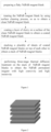
- an NdFeB permanent magnet with high coercivity and high resistivity comprising alternately stacked high-coercivity magnet layers and high resistivity layer, the high resistivity layers comprising slurry coated on surface of the NdFeB permanent magnet, characterised in that the slurry comprising heavy rare earth element or alloy powder, compound powder and organic solvent, the compound powder comprising carbide powder and/or oxide powder, the high-coercivity magnet layers comprising the heavy rare earth element or alloy powder penetrated into interior of the NdFeB permanent magnet;
- the oxide powder comprises one or more selected from the group consisting of aluminum oxide powder, silicon oxide powder, and magnesium oxide powder, cerium oxide powder, and calcium oxide powder;
- the carbide powder is one selected from the group consisting of silicon carbide powder or tungsten carbide powder, or a combination thereof.
- the present invention has the following advantageous effects as compared to the prior art.
- sintered NdFeB course magnet in Step S1, can be processed into flaky NdFeB magnet blank by using any known methods; furthermore, the NdFeB magnet blank has a thickness in a range from 1.5 mm to 6 mm.
- Step 2 impurities and oil stains can be removed from the surface of the flaky NdFeB magnet blank by the surface cleaning process, so that a clean and oil-free surface can be obtained; more preferably, the surface cleaning process is pickling.
- the slurry comprises from 27 to 40 by mass of heavy rare earth powder, from 0.2 to 1.5 by mass of compound powder and from 58.5 to 72.8 by mass of organic solvent.
- the heavy rare earth powder comprises heavy rare earth elemental powder and/or heavy rare earth alloy powder. Based on the principle of the grain boundary diffusion process, heavy rare earth elements penetrate into the inside of the flaky magnet at high temperature, and forms a (Nd, Dy) 2 Fe 14 B phase with a high magnetocrystalline anisotropy field on the surface of the crystalline grain, thereby increasing the coercivity of the magnet.
- the heavy rare earth element in the heavy rare earth powder is Dy element and/or Tb element; in particular, the heavy rare earth powder comprises one or more selected from the group consisting of Dy elemental powder, Tb elemental powder, Dy alloy powder, and Tb alloy powder.
- the Dy alloy powder is alloy powder formed by a combination of the Dy element with one or more selected from the group consisting of Al, Cu, Ga, Fe, Co elements; and the Tb alloy powder is alloy powder formed by a combination of the Tb element with one or more selected from the group consisting of Al, Cu, Ga, Fe, Co elements; furthermore, the heavy rare earth alloy powder comprises one or more of the plurality of Dy alloy powder and/or one or more of the plurality of Tb alloy powder.
- the heavy rare earth powder has an average particle size in a range from 1 to 5 ⁇ m.
- the compound powder comprises carbide powder and/or oxide powder; furthermore, the oxide powder comprises one or more selected from the group consisting of aluminum oxide powder, silicon oxide powder, magnesium oxide powder, cerium oxide powder, and calcium oxide powder; more preferably, the oxide powder is aluminum oxide powder or calcium oxide powder.
- the interlayer contains a high proportion of non-conductive elements, such as oxygen or carbon, whereby the resistivity of the whole magnet is further increased, that is, coercivity and resistivity of the NdFeB permanent magnets are increased at the same time by using the method provided in the present invention.
- the carbide powder is one selected from the group consisting of silicon carbide powder or tungsten carbide powder, or a combination thereof; more preferably, the carbide powder is silicon carbide powder.
- the compound powder has an average particle size in a range from 0.1 to 200 ⁇ m.
- the organic solvent comprises one or more selected from the group consisting of absolute ethanol, glycerin, and ethylene glycol; preferably, the organic solvent is absolute ethanol.
- Step S3 coating is performed under the protection of the nitrogen.
- the slurry, coated on the surface of the clean NdFeB magnet blank, has a thickness in a range from 10 to 30 micron.
- Step S4 the coated NdFeB magnet blanks are stacked on top of each other in a direction of thickness, wherein two to six layers of magnet blanks are stacked; more preferably, three layers of magnet blanks are stacked.
- the three-stage heat treatment process further comprises: during the first stage of heat treatment, the blank is exposed to a high temperature of 1000°C-1100°C for 4 hours to 6 hours; during the second stage of heat treatment, the blank is exposed to a high temperature of 850°C-950°C for 4 hours to 10 hours; and during the third stage of heat treatment, the blank is exposed to a high temperature of 450°C-550°C for 2 hours to 6 hours.
- an NdFeB permanent magnet with high coercivity and high resistivity formed by using the above-mentioned method, the NdFeB permanent magnet comprising alternately stacked high-coercivity magnet layers and high resistivity layer 2.
- Grade 45SH magnets are used in the following examples and control examples.
- the magnets are processed to square magnets having a thickness of 30 mm ⁇ 30 mm ⁇ 2mm after being subjected to sintering at a high temperature, and the magnets are stacked on top of each other in a thickness direction of 2 mm.
- compositions of the slurry used in the examples and the control examples are shown in Table 1: Table 1: Composition Ratio of Slurry and Powder Particle Size in Examples 1-3 and Control Examples 1-3 No. Compositions of Slurry Composition Ratio of Slurry(% by weight) Average Particle Size ( ⁇ m)
- Example 1 RE-T powder Dy-Fe 35 3.5 T-X powder Aluminum oxide 1.5 0.023 ET Ethyl alcohol 63.5 /
- Example 2 RE-T powder Tb-Cu 37 3.2 T-X powder Silicon carbide 0.7 0.042 ET Ethyl alcohol 62.3
- Example 3 RE-T powder Tb 30 2.8 T-X powder Calcium oxide 0.5 0.005 ET Ethyl alcohol 69.5 / Control Example 1 N/A N/A / Control Example 2 RE-T powder Tb 30.5 2.8 T-X powder N/A / / ET Ethyl alcohol 69.5 / Control Example 3 RE-T powder Tb 30 2.8 T-X powder Calcium oxide 4 0.005 ET Ethyl alcohol 69.5
- This example provides a method for preparing an NdFeB permanent magnet with high coercivity and high resistivity, comprising the steps of:
- Examples 2-3 are established based on Example 1, however, they differ from Example 1 in that the composition ratio of slurry and the powder particle size are different.
- the slurry of Examples 2-3 was prepared according to the composition ratio and the powder particle size shown in Table 1, and an NdFeB permanent magnet with high coercivity and high resistivity was prepared according to the method shown in Step S1.
- Control example 2 is established based on Example 1, however, it differs from Example 1 in that the composition ratio of slurry and the powder particle size are different.
- the slurry of Control example 2 was prepared according to the composition ratio and the powder particle size shown in Table 1, and an NdFeB permanent magnet with high coercivity and high resistivity was prepared according to the method shown in Step S1.
- Control example 3 is established based on Example 1, however, it differs from Example 1 in that the composition ratio of slurry and the powder particle size are different.
- the slurry of Control example 3 was prepared according to the composition ratio and the powder particle size shown in Table 1, and an NdFeB permanent magnet with high coercivity and high resistivity was prepared according to the method shown in Step S1.
- NdFeB permanent magnets obtained in Examples 1-3 and Control Examples 1-3 were processed into sample columns having dimensions of 10 mm ⁇ 10 mm ⁇ 6 mm to measure magnetic properties.
- the performance test method refers to GB13560-2007 .
- NdFeB permanent magnets obtained in Examples 1-3 and Control Examples 1-3 were processed into samples having dimension of 2 mm ⁇ 2 mm ⁇ 6 mm to measure resistivity.
- Test result is shown in Figure 2 : Table 2. Coercivity and resistivity of NdFeB permanent magnets obtained in Examples 1-3 and Control Examples 1-3 NO. Spraying Thickness ( ⁇ m) Resistivity ( ⁇ cm) Remanence (T) Coercivity (kA/m) Example 1 20 2523 1.319 2181.04 Example 2 20 3169 1.318 2348.2 Example 3 15 2847 1.322 2411.88 Control Example1 N/A 151 1.345 1639.76 Control Example 2 15 149 1.323 2419.84 Control Example 3 15 magnetic layer is not well bonded with layer, so test cannot be done 1.325 2372.08
- coercivity of slurry-coated NdFeB permanent magnets is increased.
- coercivity of the NdFeB permanent magnet, onto which slurry containing Dy is sprayed is increased by 541.28 kA/m, as shown in Example 1.
- Coercivity of the NdFeB permanent magnet, onto which slurry containing Tb is sprayed is increased by 772.12 kA/m, as shown in Example 3.
- Example 3 Comparing the test results of Example 3 and Control Example 3, it can be seen that if the content of the compound powder in the slurry is too high, the stack of NdFeB magnet blanks will not be bonded together after they are subjected to the three-stage thermal diffusion process. As a result, an NdFeB permanent magnet with high coercivity and high resistivity according to the present invention cannot be formed.
- coercivity and resistivity of magnets are greatly improved by spraying slurry containing heavy rare earth powder, oxide powder and carbide powder, etc., and by performing thermal diffusion treatment on the magnets.
Landscapes
- Engineering & Computer Science (AREA)
- Power Engineering (AREA)
- Manufacturing & Machinery (AREA)
- Chemical & Material Sciences (AREA)
- Crystallography & Structural Chemistry (AREA)
- Inorganic Chemistry (AREA)
- Environmental & Geological Engineering (AREA)
- Hard Magnetic Materials (AREA)
- Manufacturing Cores, Coils, And Magnets (AREA)
- Powder Metallurgy (AREA)
Claims (14)
- - Verfahren zum Herstellen eines NdFeB-Permanentmagneten mit hoher Koerzitivkraft und hohem spezifischen Widerstand, umfassend die folgenden Schritte:Schritt S1, Vorbereiten eines flockigen NdFeB-Magnetrohlings;Schritt S2, Behandeln des NdFeB-Magnetrohlings unter Verwendung eines Oberflächenreinigungsverfahren, um einen sauberen NdFeB-Magnetrohling zu erlangen;Schritt S3: Auftragen einer Aufschlämmungsschicht auf eine Oberfläche des sauberen NdFeB-Magnetrohlings, um einen beschichteten NdFeB-Magnetrohling zu erlangen, wobei die Aufschlämmung schweres Seltenerdpulver, Verbindungspulver und organisches Lösungsmittel umfasst, wobei dasVerbundpulver Karbidpulver und/oder Oxidpulver umfasst;Schritt S4, Stapeln einer Vielzahl von Platten beschichteter NdFeB-Magnetrohlinge übereinander, um einen Stapel von NdFeB-Magnetrohlingen zu erlangen; undSchritt S5: Ausführen einer dreistufigen thermischen Diffusionsbehandlung des Stapels von NdFeB-Magnetrohlingen, um einen NdFeB-Permanentmagneten mit hoher Koerzitivkraft und hohem spezifischen Widerstand zu erlangen.
- - Verfahren zum Herstellen eines NdFeB-Permanentmagneten mit hoher Koerzitivkraft und hohem spezifischen Widerstand nach Anspruch 1, wobei in Schritt S3 die Aufschlämmung 27 bis 40 Massenanteile an schwerem Seltenerdpulver, 0,2 bis 1,5 Massenanteile an Verbindungspulver und 58,5 bis 72,8 Massenanteile an organischem Lösungsmittel umfasst.
- - Verfahren zum Herstellen eines NdFeB-Permanentmagneten mit hoher Koerzitivfeldstärke und hohem spezifischen Widerstand nach Anspruch 1, wobei in Schritt S3 das schwere Seltenerdpulver eine durchschnittliche Teilchengröße im Bereich von 1 bis 5 µm aufweist.
- - Verfahren zum Herstellen eines NdFeB-Permanentmagneten mit hoher Koerzitivfeldstärke und hohem spezifischen Widerstand nach Anspruch 1, wobei in Schritt S3 das schwere Seltenerdpulver eines oder mehrere aus der Gruppe umfasst, bestehend aus elementarem Dy-Pulver, elementarem Tb-Pulver, Dy-Legierungspulver und Tb-Legierungspulver.
- - Verfahren zum Herstellen eines NdFeB-Permanentmagneten mit hoher Koerzitivkraft und hohem spezifischen Widerstand nach Anspruch 4, wobei das Dy-Legierungspulver und das Tb-Legierungspulver Legierungspulver sind, die durch eine Kombination von Dy-Element oder Tb-Element mit einem oder mehreren Elementen aus der Gruppe, bestehend aus Al, Cu, Ga, Fe und Co gebildet sind.
- - Verfahren zum Herstellen eines NdFeB-Permanentmagneten mit hoher Koerzitivkraft und hohem spezifischen Widerstand nach Anspruch 1, wobei in Schritt S3 das Verbundpulver eine durchschnittliche Teilchengröße in einem Bereich von 0,1 bis 200 µm aufweist.
- - Verfahren zum Herstellen eines NdFeB-Permanentmagneten mit hoher Koerzitivkraft und hohem spezifischen Widerstand nach Anspruch 1, wobei in Schritt S3 das Oxidpulver eines oder mehrere umfasst, die ausgewählt sind aus der Gruppe, bestehend aus Aluminiumoxidpulver, Siliciumoxidpulver, Magnesiumoxidpulver, Ceroxidpulver und Calciumoxidpulver.
- - Verfahren zum Herstellen eines NdFeB-Permanentmagneten mit hoher Koerzitivfeldstärke und hohem spezifischen Widerstand nach Anspruch 1, wobei in Schritt S3 das Karbidpulver ausgewählt ist aus der Gruppe, bestehend aus Siliziumkarbidpulver oder Wolframkarbidpulver oder einer Kombination davon.
- - Verfahren zum Herstellen eines NdFeB-Permanentmagneten mit hoher Koerzitivkraft und hohem spezifischen Widerstand nach Anspruch 1, wobei in Schritt S3 das organische Lösungsmittel eines oder mehrere aus der Gruppe umfasst, bestehend aus absolutem Ethanol, Glycerin und Ethylenglykol.
- - Verfahren zum Herstellen eines NdFeB-Permanentmagneten mit hoher Koerzitivfeldstärke und hohem spezifischen Widerstand nach Anspruch 1, wobei in Schritt S3 die Aufschlämmung, die auf die Oberfläche des sauberen NdFeB-Magnetrohlings aufgetragen wird, eine Stärke in einem Bereich von 10 bis 30 Mikrometer aufweist.
- - Verfahren zum Herstellen eines NdFeB-Permanentmagneten mit hoher Koerzitivfeldstärke und hohem spezifischen Widerstand nach Anspruch 1, wobei in Schritt S3 die Beschichtung unter dem Schutz des Stickstoffs ausgeführt wird.
- - Verfahren zum Herstellen eines NdFeB-Permanentmagneten mit hoher Koerzitivfeldstärke und hohem spezifischen Widerstand nach Anspruch 1, wobei in Schritt S1 der NdFeB-Magnetrohling eine Stärke in einem Bereich von 1,5 bis 6 mm aufweist.
- - Verfahren zum Herstellen eines NdFeB-Permanentmagneten mit hoher Koerzitivfeldstärke und hohem spezifischen Widerstand nach Anspruch 1, wobei in Schritt S5 das dreistufige Wärmebehandlungsverfahren ferner Folgendes umfasst: während der ersten Stufe der Wärmebehandlung wird der Rohling 4 bis 6 Stunden einer hohen Temperatur von 1000 °C - 1100 °C ausgesetzt; während der zweiten Stufe der Wärmebehandlung wird der Rohling 4 bis 10 Stunden einer hohen Temperatur von 850 °C - 950 °C ausgesetzt; und während der dritten Stufe der Wärmebehandlung wird der Rohling 2 bis 6 Stunden einer hohen Temperatur von 450 °C - 550 °C ausgesetzt.
- - NdFeB-Permanentmagnet mit hoher Koerzitivkraft und hohem spezifischen Widerstand, der NdFeB-Permanentmagnet umfassend abwechselnd gestapelte Magnetschichten mit hoher Koerzitivkraft und Schichten mit hohem spezifischen Widerstand, wobei die Schichten mit hohem spezifischen Widerstand aus einer Aufschlämmung stammen, die auf die Oberfläche der NdFeB-Permanentmagnetschichten aufgetragen ist, dadurch gekennzeichnet, dass die Aufschlämmung schweres Seltenerdelement- oder Legierungspulver, Verbindungspulver und organisches Lösungsmittel umfasst, wobei das Verbindungspulver Karbidpulver und/oder Oxidpulver umfasst, wobei die Magnetschichten mit hoher Koerzitivkraft das schwere Seltenerdelement- oder Legierungspulver umfassen, das in das Innere des NdFeB-Permanentmagneten eindringt;das Oxidpulver eines oder mehrere aus der Gruppe umfasst, bestehend aus Aluminiumoxidpulver, Siliziumoxidpulver, Magnesiumoxidpulver, Ceroxidpulver und Calciumoxidpulver;das Karbidpulver ausgewählt ist aus der Gruppe, bestehend aus Siliziumkarbidpulver oder Wolframkarbidpulver oder einer Kombination davon.
Applications Claiming Priority (1)
| Application Number | Priority Date | Filing Date | Title |
|---|---|---|---|
| CN202110385184.8A CN113451036B (zh) | 2021-04-09 | 2021-04-09 | 一种高矫顽力高电阻率钕铁硼永磁体及其制备方法 |
Publications (3)
| Publication Number | Publication Date |
|---|---|
| EP4071771A1 EP4071771A1 (de) | 2022-10-12 |
| EP4071771C0 EP4071771C0 (de) | 2024-08-14 |
| EP4071771B1 true EP4071771B1 (de) | 2024-08-14 |
Family
ID=77809463
Family Applications (1)
| Application Number | Title | Priority Date | Filing Date |
|---|---|---|---|
| EP21213079.3A Active EP4071771B1 (de) | 2021-04-09 | 2021-12-08 | Ndfeb-permanentmagnet mit hoher koerzitivkraft und hohem widerstand und verfahren zur herstellung davon |
Country Status (5)
| Country | Link |
|---|---|
| US (1) | US12293868B2 (de) |
| EP (1) | EP4071771B1 (de) |
| JP (1) | JP7251834B2 (de) |
| CN (1) | CN113451036B (de) |
| WO (1) | WO2022213491A1 (de) |
Families Citing this family (3)
| Publication number | Priority date | Publication date | Assignee | Title |
|---|---|---|---|---|
| CN113517131B (zh) * | 2021-08-27 | 2022-04-29 | 杭州美磁科技有限公司 | 一种钕铁硼产品的制备工艺及运用该制备工艺制得的钕铁硼产品 |
| CN114446629A (zh) * | 2022-01-28 | 2022-05-06 | 中国科学院赣江创新研究院 | 一种风力发电机稀土磁钢及其制造方法 |
| CN118692803A (zh) * | 2024-07-02 | 2024-09-24 | 宁波韵升股份有限公司 | 一种低涡流损耗的钕铁硼磁体的制造工艺 |
Family Cites Families (31)
| Publication number | Priority date | Publication date | Assignee | Title |
|---|---|---|---|---|
| US4747874A (en) * | 1986-05-30 | 1988-05-31 | Union Oil Company Of California | Rare earth-iron-boron permanent magnets with enhanced coercivity |
| JP4753030B2 (ja) | 2006-04-14 | 2011-08-17 | 信越化学工業株式会社 | 希土類永久磁石材料の製造方法 |
| CN101211684B (zh) * | 2006-12-28 | 2010-06-30 | 宁波科田磁业有限公司 | 钕铁硼磁体的制作方法 |
| CN100559519C (zh) * | 2007-12-08 | 2009-11-11 | 宁波科田磁业有限公司 | 用钬代替镝的烧结钕铁硼永磁材料 |
| US8536614B2 (en) * | 2008-01-11 | 2013-09-17 | Industrial Technology Research Institute | Nitride semiconductor light emitting device with magnetic film |
| JP5251219B2 (ja) | 2008-04-04 | 2013-07-31 | 信越化学工業株式会社 | 永久磁石式回転機用回転子 |
| CN101812606B (zh) * | 2010-03-05 | 2012-09-05 | 宁波科田磁业有限公司 | 铸锭改铸片添加重稀土氧化物制备低成本钕铁硼的方法 |
| US8300356B2 (en) * | 2010-05-11 | 2012-10-30 | Headway Technologies, Inc. | CoFe/Ni Multilayer film with perpendicular anistropy for microwave assisted magnetic recording |
| CN101859639B (zh) * | 2010-07-06 | 2013-03-27 | 烟台正海磁性材料股份有限公司 | 一种梯度电阻R-Fe-B系磁体及其生产方法 |
| RU2476947C2 (ru) * | 2011-06-08 | 2013-02-27 | Учреждение Российской академии наук Ордена Трудового Красного Знамени Институт физики металлов Уральского отделения РАН (ИФМ УрО РАН) | СПОСОБ ПОЛУЧЕНИЯ ВЫСОКОКОЭРЦИТИВНЫХ МАГНИТОВ ИЗ СПЛАВОВ НА ОСНОВЕ Nd-Fe-B |
| JP6100168B2 (ja) | 2011-10-27 | 2017-03-22 | インターメタリックス株式会社 | NdFeB系焼結磁石の製造方法 |
| CN104051102A (zh) * | 2013-03-12 | 2014-09-17 | 北京中科三环高技术股份有限公司 | 一种稀土永磁体及其制备方法 |
| CN105051844A (zh) * | 2013-03-18 | 2015-11-11 | 因太金属株式会社 | RFeB系烧结磁铁制造方法和RFeB系烧结磁铁 |
| JP6464552B2 (ja) | 2013-10-04 | 2019-02-06 | 大同特殊鋼株式会社 | RFeB系磁石及びその製造方法 |
| CN103839669B (zh) * | 2014-02-28 | 2016-06-29 | 厦门钨业股份有限公司 | 以钕铁硼磁片制造复合磁体的方法 |
| CN103839670B (zh) * | 2014-03-18 | 2016-05-11 | 安徽大地熊新材料股份有限公司 | 一种制备高矫顽力的烧结钕铁硼永磁体的方法 |
| CN104051104B (zh) * | 2014-06-06 | 2017-06-23 | 中国科学院宁波材料技术与工程研究所 | 钕铁硼永磁磁体及其制备方法 |
| CN105469973B (zh) * | 2014-12-19 | 2017-07-18 | 北京中科三环高技术股份有限公司 | 一种r‑t‑b永磁体的制备方法 |
| CN106710765B (zh) * | 2015-07-21 | 2018-08-10 | 宁波科田磁业有限公司 | 一种高矫顽力烧结钕铁硼磁体及其制备方法 |
| CN105070498B (zh) | 2015-08-28 | 2016-12-07 | 包头天和磁材技术有限责任公司 | 提高磁体矫顽力的方法 |
| CN108063045B (zh) * | 2016-11-08 | 2020-04-21 | 中国科学院宁波材料技术与工程研究所 | 一种无重稀土钕铁硼永磁材料及其制备方法 |
| CN107546028A (zh) * | 2017-08-23 | 2018-01-05 | 宁波科田磁业有限公司 | 提高钕铁硼磁体矫顽力和抗腐蚀性的制备方法 |
| CN107578912A (zh) * | 2017-09-25 | 2018-01-12 | 烟台正海磁性材料股份有限公司 | 一种具有高矫顽力的钕铁硼磁体的制备方法 |
| CN107958761A (zh) * | 2017-11-17 | 2018-04-24 | 宁波科田磁业有限公司 | 一种焊接钕铁硼磁体及其制备方法 |
| CN109003799B (zh) * | 2018-07-06 | 2021-02-12 | 杭州永磁集团振泽磁业有限公司 | 一种高矫顽力钕铁硼磁体的制备方法 |
| JP7251264B2 (ja) | 2019-03-28 | 2023-04-04 | Tdk株式会社 | R‐t‐b系永久磁石の製造方法 |
| CN110136953B (zh) | 2019-06-17 | 2022-04-26 | 江苏科技大学 | 一种具有矫顽力梯度分布特征复合钕铁硼磁体的制备方法 |
| JP7364405B2 (ja) * | 2019-09-20 | 2023-10-18 | 信越化学工業株式会社 | 希土類磁石の製造方法 |
| CN110911150B (zh) * | 2019-11-28 | 2021-08-06 | 烟台首钢磁性材料股份有限公司 | 一种提高钕铁硼烧结永磁体矫顽力的方法 |
| CN111326307B (zh) * | 2020-03-17 | 2021-12-28 | 宁波金鸡强磁股份有限公司 | 一种渗透磁体用的涂覆材料及高矫顽力钕铁硼磁体的制备方法 |
| CN111477447A (zh) * | 2020-04-17 | 2020-07-31 | 有研稀土(荣成)有限公司 | 一种烧结钕铁硼永磁体及其制备方法 |
-
2021
- 2021-04-09 CN CN202110385184.8A patent/CN113451036B/zh active Active
- 2021-06-29 WO PCT/CN2021/103318 patent/WO2022213491A1/zh not_active Ceased
- 2021-12-07 US US17/544,745 patent/US12293868B2/en active Active
- 2021-12-08 EP EP21213079.3A patent/EP4071771B1/de active Active
- 2021-12-15 JP JP2021203110A patent/JP7251834B2/ja active Active
Also Published As
| Publication number | Publication date |
|---|---|
| JP7251834B2 (ja) | 2023-04-04 |
| JP2022161809A (ja) | 2022-10-21 |
| CN113451036B (zh) | 2022-10-25 |
| EP4071771A1 (de) | 2022-10-12 |
| WO2022213491A1 (zh) | 2022-10-13 |
| US20220328244A1 (en) | 2022-10-13 |
| CN113451036A (zh) | 2021-09-28 |
| US12293868B2 (en) | 2025-05-06 |
| EP4071771C0 (de) | 2024-08-14 |
Similar Documents
| Publication | Publication Date | Title |
|---|---|---|
| EP4071771B1 (de) | Ndfeb-permanentmagnet mit hoher koerzitivkraft und hohem widerstand und verfahren zur herstellung davon | |
| EP2555206B1 (de) | Seltenerd-sintermagnet, verfahren zu seiner herstellung sowie motor und automobil damit | |
| CN105658835B (zh) | 一种低b的稀土磁铁 | |
| EP1744328B1 (de) | Seltenerdmagnet mit hoher Festigkeit und mit grossem elektrischem Widerstand | |
| EP2555207A1 (de) | Seltenerd-sintermagnet, verfahren zu seiner herstellung sowie motor und automobil damit | |
| CN108154987B (zh) | R-t-b系永久磁铁 | |
| WO2016095869A1 (zh) | 一种r-t-b永磁体的制备方法 | |
| JP7769934B2 (ja) | ネオジム鉄ボロン磁石及びその製造方法並びに応用 | |
| EP0289599B1 (de) | Verfahren zur herstellung von dauermagneten | |
| KR101906067B1 (ko) | R-Fe-B류 소결 자성체 제조방법 | |
| JP7251264B2 (ja) | R‐t‐b系永久磁石の製造方法 | |
| KR102589802B1 (ko) | 네오디뮴철붕소 자성체재료, 원료조성물과 제조방법 및 응용 | |
| EP4152348B1 (de) | Herstellungsverfahren für hochleistungs-neodym-eisen-bor-permanentmagnetmaterial ohne schwere seltene erden | |
| CN111326306B (zh) | 一种r-t-b系永磁材料及其制备方法和应用 | |
| EP4287227A1 (de) | Diffusionsquellenmaterial und dessen verwendung zur herstellung von ndfeb-magneten | |
| CN106920669B (zh) | 一种R-Fe-B系烧结磁体的制备方法 | |
| CN114927302A (zh) | 稀土磁体及其制备方法 | |
| EP3633696B1 (de) | Gesinterter seltenerd-magnet | |
| US11145444B2 (en) | R-T-B-based sintered magnet | |
| CN110993311A (zh) | 一种晶界扩散制备高性能大块钕铁硼磁体的方法 | |
| CN115775678B (zh) | 一种提高钕铁硼永磁材料厚产品内禀矫顽力的方法 | |
| CN119446698A (zh) | 一种大尺寸高性能烧结钕铁硼磁体制备方法及其应用 | |
| CN111312507A (zh) | 一种提高稀土-铁-硼永磁体强度的方法 | |
| CN117497276A (zh) | 一种基于可选区域晶界扩散的R-T-Ga-B稀土永磁体及其制备方法 | |
| CN119230277B (zh) | 一种烧结钕铁硼压力辅助增强晶界扩散的方法及其磁体 |
Legal Events
| Date | Code | Title | Description |
|---|---|---|---|
| PUAI | Public reference made under article 153(3) epc to a published international application that has entered the european phase |
Free format text: ORIGINAL CODE: 0009012 |
|
| STAA | Information on the status of an ep patent application or granted ep patent |
Free format text: STATUS: THE APPLICATION HAS BEEN PUBLISHED |
|
| AK | Designated contracting states |
Kind code of ref document: A1 Designated state(s): AL AT BE BG CH CY CZ DE DK EE ES FI FR GB GR HR HU IE IS IT LI LT LU LV MC MK MT NL NO PL PT RO RS SE SI SK SM TR |
|
| STAA | Information on the status of an ep patent application or granted ep patent |
Free format text: STATUS: REQUEST FOR EXAMINATION WAS MADE |
|
| 17P | Request for examination filed |
Effective date: 20230412 |
|
| RBV | Designated contracting states (corrected) |
Designated state(s): AL AT BE BG CH CY CZ DE DK EE ES FI FR GB GR HR HU IE IS IT LI LT LU LV MC MK MT NL NO PL PT RO RS SE SI SK SM TR |
|
| GRAP | Despatch of communication of intention to grant a patent |
Free format text: ORIGINAL CODE: EPIDOSNIGR1 |
|
| STAA | Information on the status of an ep patent application or granted ep patent |
Free format text: STATUS: GRANT OF PATENT IS INTENDED |
|
| RIC1 | Information provided on ipc code assigned before grant |
Ipc: H01F 41/02 20060101ALI20240214BHEP Ipc: H01F 1/057 20060101AFI20240214BHEP |
|
| INTG | Intention to grant announced |
Effective date: 20240314 |
|
| GRAS | Grant fee paid |
Free format text: ORIGINAL CODE: EPIDOSNIGR3 |
|
| GRAA | (expected) grant |
Free format text: ORIGINAL CODE: 0009210 |
|
| STAA | Information on the status of an ep patent application or granted ep patent |
Free format text: STATUS: THE PATENT HAS BEEN GRANTED |
|
| AK | Designated contracting states |
Kind code of ref document: B1 Designated state(s): AL AT BE BG CH CY CZ DE DK EE ES FI FR GB GR HR HU IE IS IT LI LT LU LV MC MK MT NL NO PL PT RO RS SE SI SK SM TR |
|
| REG | Reference to a national code |
Ref country code: GB Ref legal event code: FG4D |
|
| REG | Reference to a national code |
Ref country code: CH Ref legal event code: EP |
|
| REG | Reference to a national code |
Ref country code: DE Ref legal event code: R096 Ref document number: 602021017149 Country of ref document: DE |
|
| REG | Reference to a national code |
Ref country code: IE Ref legal event code: FG4D |
|
| U01 | Request for unitary effect filed |
Effective date: 20240911 |
|
| U07 | Unitary effect registered |
Designated state(s): AT BE BG DE DK EE FI FR IT LT LU LV MT NL PT RO SE SI Effective date: 20240926 |
|
| PG25 | Lapsed in a contracting state [announced via postgrant information from national office to epo] |
Ref country code: NO Free format text: LAPSE BECAUSE OF FAILURE TO SUBMIT A TRANSLATION OF THE DESCRIPTION OR TO PAY THE FEE WITHIN THE PRESCRIBED TIME-LIMIT Effective date: 20241114 |
|
| PG25 | Lapsed in a contracting state [announced via postgrant information from national office to epo] |
Ref country code: GR Free format text: LAPSE BECAUSE OF FAILURE TO SUBMIT A TRANSLATION OF THE DESCRIPTION OR TO PAY THE FEE WITHIN THE PRESCRIBED TIME-LIMIT Effective date: 20241115 Ref country code: PL Free format text: LAPSE BECAUSE OF FAILURE TO SUBMIT A TRANSLATION OF THE DESCRIPTION OR TO PAY THE FEE WITHIN THE PRESCRIBED TIME-LIMIT Effective date: 20240814 |
|
| PG25 | Lapsed in a contracting state [announced via postgrant information from national office to epo] |
Ref country code: IS Free format text: LAPSE BECAUSE OF FAILURE TO SUBMIT A TRANSLATION OF THE DESCRIPTION OR TO PAY THE FEE WITHIN THE PRESCRIBED TIME-LIMIT Effective date: 20241214 |
|
| PG25 | Lapsed in a contracting state [announced via postgrant information from national office to epo] |
Ref country code: HR Free format text: LAPSE BECAUSE OF FAILURE TO SUBMIT A TRANSLATION OF THE DESCRIPTION OR TO PAY THE FEE WITHIN THE PRESCRIBED TIME-LIMIT Effective date: 20240814 |
|
| PG25 | Lapsed in a contracting state [announced via postgrant information from national office to epo] |
Ref country code: RS Free format text: LAPSE BECAUSE OF FAILURE TO SUBMIT A TRANSLATION OF THE DESCRIPTION OR TO PAY THE FEE WITHIN THE PRESCRIBED TIME-LIMIT Effective date: 20241114 Ref country code: ES Free format text: LAPSE BECAUSE OF FAILURE TO SUBMIT A TRANSLATION OF THE DESCRIPTION OR TO PAY THE FEE WITHIN THE PRESCRIBED TIME-LIMIT Effective date: 20240814 |
|
| U20 | Renewal fee for the european patent with unitary effect paid |
Year of fee payment: 4 Effective date: 20241226 |
|
| PG25 | Lapsed in a contracting state [announced via postgrant information from national office to epo] |
Ref country code: RS Free format text: LAPSE BECAUSE OF FAILURE TO SUBMIT A TRANSLATION OF THE DESCRIPTION OR TO PAY THE FEE WITHIN THE PRESCRIBED TIME-LIMIT Effective date: 20241114 Ref country code: PL Free format text: LAPSE BECAUSE OF FAILURE TO SUBMIT A TRANSLATION OF THE DESCRIPTION OR TO PAY THE FEE WITHIN THE PRESCRIBED TIME-LIMIT Effective date: 20240814 Ref country code: NO Free format text: LAPSE BECAUSE OF FAILURE TO SUBMIT A TRANSLATION OF THE DESCRIPTION OR TO PAY THE FEE WITHIN THE PRESCRIBED TIME-LIMIT Effective date: 20241114 Ref country code: IS Free format text: LAPSE BECAUSE OF FAILURE TO SUBMIT A TRANSLATION OF THE DESCRIPTION OR TO PAY THE FEE WITHIN THE PRESCRIBED TIME-LIMIT Effective date: 20241214 Ref country code: HR Free format text: LAPSE BECAUSE OF FAILURE TO SUBMIT A TRANSLATION OF THE DESCRIPTION OR TO PAY THE FEE WITHIN THE PRESCRIBED TIME-LIMIT Effective date: 20240814 Ref country code: GR Free format text: LAPSE BECAUSE OF FAILURE TO SUBMIT A TRANSLATION OF THE DESCRIPTION OR TO PAY THE FEE WITHIN THE PRESCRIBED TIME-LIMIT Effective date: 20241115 Ref country code: ES Free format text: LAPSE BECAUSE OF FAILURE TO SUBMIT A TRANSLATION OF THE DESCRIPTION OR TO PAY THE FEE WITHIN THE PRESCRIBED TIME-LIMIT Effective date: 20240814 |
|
| PG25 | Lapsed in a contracting state [announced via postgrant information from national office to epo] |
Ref country code: SM Free format text: LAPSE BECAUSE OF FAILURE TO SUBMIT A TRANSLATION OF THE DESCRIPTION OR TO PAY THE FEE WITHIN THE PRESCRIBED TIME-LIMIT Effective date: 20240814 |
|
| PG25 | Lapsed in a contracting state [announced via postgrant information from national office to epo] |
Ref country code: CZ Free format text: LAPSE BECAUSE OF FAILURE TO SUBMIT A TRANSLATION OF THE DESCRIPTION OR TO PAY THE FEE WITHIN THE PRESCRIBED TIME-LIMIT Effective date: 20240814 |
|
| PG25 | Lapsed in a contracting state [announced via postgrant information from national office to epo] |
Ref country code: SK Free format text: LAPSE BECAUSE OF FAILURE TO SUBMIT A TRANSLATION OF THE DESCRIPTION OR TO PAY THE FEE WITHIN THE PRESCRIBED TIME-LIMIT Effective date: 20240814 |
|
| PLBE | No opposition filed within time limit |
Free format text: ORIGINAL CODE: 0009261 |
|
| STAA | Information on the status of an ep patent application or granted ep patent |
Free format text: STATUS: NO OPPOSITION FILED WITHIN TIME LIMIT |
|
| PG25 | Lapsed in a contracting state [announced via postgrant information from national office to epo] |
Ref country code: MC Free format text: LAPSE BECAUSE OF FAILURE TO SUBMIT A TRANSLATION OF THE DESCRIPTION OR TO PAY THE FEE WITHIN THE PRESCRIBED TIME-LIMIT Effective date: 20240814 |
|
| 26N | No opposition filed |
Effective date: 20250515 |
|
| REG | Reference to a national code |
Ref country code: CH Ref legal event code: PL |
|
| PG25 | Lapsed in a contracting state [announced via postgrant information from national office to epo] |
Ref country code: CH Free format text: LAPSE BECAUSE OF NON-PAYMENT OF DUE FEES Effective date: 20241231 |
|
| PG25 | Lapsed in a contracting state [announced via postgrant information from national office to epo] |
Ref country code: IE Free format text: LAPSE BECAUSE OF NON-PAYMENT OF DUE FEES Effective date: 20241208 |
|
| U20 | Renewal fee for the european patent with unitary effect paid |
Year of fee payment: 5 Effective date: 20251230 |