EP3633696B1 - Gesinterter seltenerd-magnet - Google Patents
Gesinterter seltenerd-magnet Download PDFInfo
- Publication number
- EP3633696B1 EP3633696B1 EP19198188.5A EP19198188A EP3633696B1 EP 3633696 B1 EP3633696 B1 EP 3633696B1 EP 19198188 A EP19198188 A EP 19198188A EP 3633696 B1 EP3633696 B1 EP 3633696B1
- Authority
- EP
- European Patent Office
- Prior art keywords
- layer
- max
- particle
- concentration
- sintered magnet
- Prior art date
- Legal status (The legal status is an assumption and is not a legal conclusion. Google has not performed a legal analysis and makes no representation as to the accuracy of the status listed.)
- Active
Links
Images


Classifications
-
- H—ELECTRICITY
- H01—ELECTRIC ELEMENTS
- H01F—MAGNETS; INDUCTANCES; TRANSFORMERS; SELECTION OF MATERIALS FOR THEIR MAGNETIC PROPERTIES
- H01F1/00—Magnets or magnetic bodies characterised by the magnetic materials therefor; Selection of materials for their magnetic properties
- H01F1/01—Magnets or magnetic bodies characterised by the magnetic materials therefor; Selection of materials for their magnetic properties of inorganic materials
- H01F1/03—Magnets or magnetic bodies characterised by the magnetic materials therefor; Selection of materials for their magnetic properties of inorganic materials characterised by their coercivity
- H01F1/032—Magnets or magnetic bodies characterised by the magnetic materials therefor; Selection of materials for their magnetic properties of inorganic materials characterised by their coercivity of hard-magnetic materials
- H01F1/04—Magnets or magnetic bodies characterised by the magnetic materials therefor; Selection of materials for their magnetic properties of inorganic materials characterised by their coercivity of hard-magnetic materials metals or alloys
- H01F1/047—Alloys characterised by their composition
- H01F1/053—Alloys characterised by their composition containing rare earth metals
- H01F1/0536—Alloys characterised by their composition containing rare earth metals sintered
-
- B—PERFORMING OPERATIONS; TRANSPORTING
- B22—CASTING; POWDER METALLURGY
- B22F—WORKING METALLIC POWDER; MANUFACTURE OF ARTICLES FROM METALLIC POWDER; MAKING METALLIC POWDER; APPARATUS OR DEVICES SPECIALLY ADAPTED FOR METALLIC POWDER
- B22F1/00—Metallic powder; Treatment of metallic powder, e.g. to facilitate working or to improve properties
- B22F1/16—Metallic particles coated with a non-metal
-
- C—CHEMISTRY; METALLURGY
- C22—METALLURGY; FERROUS OR NON-FERROUS ALLOYS; TREATMENT OF ALLOYS OR NON-FERROUS METALS
- C22C—ALLOYS
- C22C1/00—Making non-ferrous alloys
- C22C1/04—Making non-ferrous alloys by powder metallurgy
- C22C1/0433—Nickel- or cobalt-based alloys
- C22C1/0441—Alloys based on intermetallic compounds of the type rare earth - Co, Ni
-
- H—ELECTRICITY
- H01—ELECTRIC ELEMENTS
- H01F—MAGNETS; INDUCTANCES; TRANSFORMERS; SELECTION OF MATERIALS FOR THEIR MAGNETIC PROPERTIES
- H01F1/00—Magnets or magnetic bodies characterised by the magnetic materials therefor; Selection of materials for their magnetic properties
- H01F1/01—Magnets or magnetic bodies characterised by the magnetic materials therefor; Selection of materials for their magnetic properties of inorganic materials
- H01F1/03—Magnets or magnetic bodies characterised by the magnetic materials therefor; Selection of materials for their magnetic properties of inorganic materials characterised by their coercivity
- H01F1/032—Magnets or magnetic bodies characterised by the magnetic materials therefor; Selection of materials for their magnetic properties of inorganic materials characterised by their coercivity of hard-magnetic materials
- H01F1/04—Magnets or magnetic bodies characterised by the magnetic materials therefor; Selection of materials for their magnetic properties of inorganic materials characterised by their coercivity of hard-magnetic materials metals or alloys
- H01F1/047—Alloys characterised by their composition
- H01F1/053—Alloys characterised by their composition containing rare earth metals
- H01F1/055—Alloys characterised by their composition containing rare earth metals and magnetic transition metals, e.g. SmCo5
- H01F1/057—Alloys characterised by their composition containing rare earth metals and magnetic transition metals, e.g. SmCo5 and IIIa elements, e.g. Nd2Fe14B
- H01F1/0571—Alloys characterised by their composition containing rare earth metals and magnetic transition metals, e.g. SmCo5 and IIIa elements, e.g. Nd2Fe14B in the form of particles, e.g. rapid quenched powders or ribbon flakes
- H01F1/0572—Alloys characterised by their composition containing rare earth metals and magnetic transition metals, e.g. SmCo5 and IIIa elements, e.g. Nd2Fe14B in the form of particles, e.g. rapid quenched powders or ribbon flakes with a protective layer
-
- H—ELECTRICITY
- H01—ELECTRIC ELEMENTS
- H01F—MAGNETS; INDUCTANCES; TRANSFORMERS; SELECTION OF MATERIALS FOR THEIR MAGNETIC PROPERTIES
- H01F1/00—Magnets or magnetic bodies characterised by the magnetic materials therefor; Selection of materials for their magnetic properties
- H01F1/01—Magnets or magnetic bodies characterised by the magnetic materials therefor; Selection of materials for their magnetic properties of inorganic materials
- H01F1/03—Magnets or magnetic bodies characterised by the magnetic materials therefor; Selection of materials for their magnetic properties of inorganic materials characterised by their coercivity
- H01F1/032—Magnets or magnetic bodies characterised by the magnetic materials therefor; Selection of materials for their magnetic properties of inorganic materials characterised by their coercivity of hard-magnetic materials
- H01F1/04—Magnets or magnetic bodies characterised by the magnetic materials therefor; Selection of materials for their magnetic properties of inorganic materials characterised by their coercivity of hard-magnetic materials metals or alloys
- H01F1/047—Alloys characterised by their composition
- H01F1/053—Alloys characterised by their composition containing rare earth metals
- H01F1/055—Alloys characterised by their composition containing rare earth metals and magnetic transition metals, e.g. SmCo5
- H01F1/057—Alloys characterised by their composition containing rare earth metals and magnetic transition metals, e.g. SmCo5 and IIIa elements, e.g. Nd2Fe14B
- H01F1/0571—Alloys characterised by their composition containing rare earth metals and magnetic transition metals, e.g. SmCo5 and IIIa elements, e.g. Nd2Fe14B in the form of particles, e.g. rapid quenched powders or ribbon flakes
- H01F1/0575—Alloys characterised by their composition containing rare earth metals and magnetic transition metals, e.g. SmCo5 and IIIa elements, e.g. Nd2Fe14B in the form of particles, e.g. rapid quenched powders or ribbon flakes pressed, sintered or bonded together
- H01F1/0577—Alloys characterised by their composition containing rare earth metals and magnetic transition metals, e.g. SmCo5 and IIIa elements, e.g. Nd2Fe14B in the form of particles, e.g. rapid quenched powders or ribbon flakes pressed, sintered or bonded together sintered
-
- H—ELECTRICITY
- H01—ELECTRIC ELEMENTS
- H01F—MAGNETS; INDUCTANCES; TRANSFORMERS; SELECTION OF MATERIALS FOR THEIR MAGNETIC PROPERTIES
- H01F1/00—Magnets or magnetic bodies characterised by the magnetic materials therefor; Selection of materials for their magnetic properties
- H01F1/01—Magnets or magnetic bodies characterised by the magnetic materials therefor; Selection of materials for their magnetic properties of inorganic materials
- H01F1/03—Magnets or magnetic bodies characterised by the magnetic materials therefor; Selection of materials for their magnetic properties of inorganic materials characterised by their coercivity
- H01F1/12—Magnets or magnetic bodies characterised by the magnetic materials therefor; Selection of materials for their magnetic properties of inorganic materials characterised by their coercivity of soft-magnetic materials
- H01F1/14—Magnets or magnetic bodies characterised by the magnetic materials therefor; Selection of materials for their magnetic properties of inorganic materials characterised by their coercivity of soft-magnetic materials metals or alloys
- H01F1/147—Alloys characterised by their composition
- H01F1/153—Amorphous metallic alloys, e.g. glassy metals
- H01F1/15325—Amorphous metallic alloys, e.g. glassy metals containing rare earths
-
- H—ELECTRICITY
- H01—ELECTRIC ELEMENTS
- H01F—MAGNETS; INDUCTANCES; TRANSFORMERS; SELECTION OF MATERIALS FOR THEIR MAGNETIC PROPERTIES
- H01F41/00—Apparatus or processes specially adapted for manufacturing or assembling magnets, inductances or transformers; Apparatus or processes specially adapted for manufacturing materials characterised by their magnetic properties
- H01F41/02—Apparatus or processes specially adapted for manufacturing or assembling magnets, inductances or transformers; Apparatus or processes specially adapted for manufacturing materials characterised by their magnetic properties for manufacturing cores, coils, or magnets
- H01F41/0253—Apparatus or processes specially adapted for manufacturing or assembling magnets, inductances or transformers; Apparatus or processes specially adapted for manufacturing materials characterised by their magnetic properties for manufacturing cores, coils, or magnets for manufacturing permanent magnets
- H01F41/026—Apparatus or processes specially adapted for manufacturing or assembling magnets, inductances or transformers; Apparatus or processes specially adapted for manufacturing materials characterised by their magnetic properties for manufacturing cores, coils, or magnets for manufacturing permanent magnets protecting methods against environmental influences, e.g. oxygen, by surface treatment
-
- H—ELECTRICITY
- H01—ELECTRIC ELEMENTS
- H01F—MAGNETS; INDUCTANCES; TRANSFORMERS; SELECTION OF MATERIALS FOR THEIR MAGNETIC PROPERTIES
- H01F41/00—Apparatus or processes specially adapted for manufacturing or assembling magnets, inductances or transformers; Apparatus or processes specially adapted for manufacturing materials characterised by their magnetic properties
- H01F41/02—Apparatus or processes specially adapted for manufacturing or assembling magnets, inductances or transformers; Apparatus or processes specially adapted for manufacturing materials characterised by their magnetic properties for manufacturing cores, coils, or magnets
- H01F41/0253—Apparatus or processes specially adapted for manufacturing or assembling magnets, inductances or transformers; Apparatus or processes specially adapted for manufacturing materials characterised by their magnetic properties for manufacturing cores, coils, or magnets for manufacturing permanent magnets
- H01F41/0293—Apparatus or processes specially adapted for manufacturing or assembling magnets, inductances or transformers; Apparatus or processes specially adapted for manufacturing materials characterised by their magnetic properties for manufacturing cores, coils, or magnets for manufacturing permanent magnets diffusion of rare earth elements, e.g. Tb, Dy or Ho, into permanent magnets
-
- C—CHEMISTRY; METALLURGY
- C22—METALLURGY; FERROUS OR NON-FERROUS ALLOYS; TREATMENT OF ALLOYS OR NON-FERROUS METALS
- C22C—ALLOYS
- C22C2202/00—Physical properties
- C22C2202/02—Magnetic
-
- Y—GENERAL TAGGING OF NEW TECHNOLOGICAL DEVELOPMENTS; GENERAL TAGGING OF CROSS-SECTIONAL TECHNOLOGIES SPANNING OVER SEVERAL SECTIONS OF THE IPC; TECHNICAL SUBJECTS COVERED BY FORMER USPC CROSS-REFERENCE ART COLLECTIONS [XRACs] AND DIGESTS
- Y02—TECHNOLOGIES OR APPLICATIONS FOR MITIGATION OR ADAPTATION AGAINST CLIMATE CHANGE
- Y02T—CLIMATE CHANGE MITIGATION TECHNOLOGIES RELATED TO TRANSPORTATION
- Y02T10/00—Road transport of goods or passengers
- Y02T10/60—Other road transportation technologies with climate change mitigation effect
- Y02T10/64—Electric machine technologies in electromobility
Definitions
- the present invention relates to a high-performance sintered rare earth magnet capable of reducing the amount of expensive Tb and Dy used.
- Nd-Fe-B sintered magnet An application range of a Nd-Fe-B sintered magnet continues to expand from hard disk drives to air conditioners, industrial motors, generators and drive motors for hybrid vehicles and electric vehicles, and the like. Since the magnets are exposed to high temperature in applications for air conditioner compressor motors and automotive applications, which are expected to be developed in the future, Dy and Tb are essentially added due to requirement of stability of properties under high temperature, that is, heat resistance; on the other hand, from the viewpoint of recent resource problems, how to reduce Dy and Tb has been an important issue.
- a reverse magnetic domain a small reverse magnetized region, called a reverse magnetic domain, is generated at an interface of Nd 2 Fe 14 B crystal grains that are main components responsible for magnetism, and the magnetization is reversed by the growth of the reverse magnetic domain.
- the maximum coercivity is equal to the anisotropic magnetic field (6.4 MA/m) of a Nd 2 Fe 14 B compound; however, due to an influence of a decrease in the anisotropic magnetic field caused by disorder of a crystal structure in the vicinity of a crystal grain boundary and a leakage magnetic field caused by structural morphology, the coercivity actually obtained is about 15% (1 MA/m) of the anisotropic magnetic field.
- Nd-Fe-B magnet In such a Nd-Fe-B magnet, it is known that the anisotropic magnetic field becomes significantly higher than Nd 2 Fe 14 B in a case where a site of Nd is substituted with Dy or Tb. Therefore, when a part of Nd is substituted with Dy or Tb, the anisotropic magnetic field is increased and thereby the coercivity is also enhanced.
- Dy and Tb cause saturation magnetic polarization of a magnetic compound to be greatly reduced, a trade-off with the decrease in residual magnetic flux density is not avoidable as long as these elements are added to enhance the coercivity.
- the sintering temperature is as high as 1,050°C to 1,100°C
- Dy and Tb are diffused to the inside of about 1 to 4 ⁇ m from an interface of main phase crystal grains about 5 to 10 ⁇ m in diameter, and a concentration difference with a grain center is not large.
- the following grain boundary diffusion process has been developed to overcome this problem.
- a grain boundary diffusion process In a grain boundary diffusion process, once a sintered body is prepared, then Dy or Tb is supplied from a surface of the sintered body, a heavy rare earth is diffused into a magnet through a Nd-rich phase which is in a liquid phase at temperature lower than sintering temperature, and Nd is substituted with a heavy rare earth having high concentration only in the vicinity of the surface of the main phase crystal grain.
- Various technologies have been reported for the supply form of Dy or Tb as described below, and it is understood that the grain boundary diffusion process is highly positioned as a method of producing a high performance magnet.
- the limit of enhanced coercivity increase is about 400 kA/m in Dy diffusion and about 700 kA/m in Tb diffusion.
- Patent Documents 9 and 10 also disclose methods for producing sintered R-T-B based magnets, where R is a rare-earth element and T is a transition metal element.
- the present invention has been made in view of the above-described conventional problems, and there is provided a R-Fe-B sintered magnet (R is at least one element selected from the rare earth element containing Sc and Y) with higher performance than those manufactured by conventional grain boundary diffusion technology.
- the present invention provides a rare earth sintered magnet having the following particle morphology.
- an R-Fe-B sintered magnet which has high performance and can reduce the amount of Tb or Dy used.
- the rare earth sintered magnet of the present invention is, as described above, the sintered magnet body having the R 1 a R 2 b T c M d B e composition with the crystal phase having the Nd 2 Fe 14 B tetragonal structure as a main phase, and includes a unique form of multi-layer main phase particle having the multiple layers as the particle present in the vicinity of the magnet surface as described in [1].
- the sintered magnet body having such a unique form is can be obtained by diffusing R 2 (R 2 is one or two elements selected from Tb and Dy) to an R-T-B magnet body (R is at least one element selected from rare earth elements including Sc and Y, and T is Fe or Fe and Co).
- the above sintered magnet body can be obtained by diffusing R 2 (R 2 is one or two elements selected from Tb and Dy) from a surface of an anisotropic sintered body consisting of the R 1 a R 2 b T c M d B e composition
- R 1 is at least one element selected from rare earth elements including Sc and Y, and except for Tb and Dy
- R 2 is one or two elements selected from Tb and Dy
- T is Fe or Fe and Co
- M is at least one element selected from the group consisting of Al, Cu, Zn, In, Si, P, S, Ti, V, Cr, Mn, Ni, Ga, Ge, Zr, Nb, Mo, Pd, Ag, Cd, Sn, Sb, Hf, Ta, and W
- B is boron, a to e satisfy, by at% of the alloy composition, 12 ⁇ a + b ⁇ 17, 0.01 ⁇ d ⁇ 11, and 3 ⁇ e ⁇ 15, and the remainder is c) having the Nd 2 Fe
- the anisotropic sintered body having the R 1 a R 2 b T c M d B e composition can be obtained by roughly pulverizing, finely pulverizing, forming, and sintering a mother alloy according to a conventional method.
- the mother alloy contains R, T, M, and B.
- R is at least one element selected from rare earth elements including Sc and Y, and specific examples thereof include Sc, Y, La, Ce, Pr, Nd, Sm, Eu, Gd, Tb, Dy, Ho, Er, Yb, and Lu, and preferably, Nd, Pr, and Dy are mainly used.
- the rare earth elements containing Sc and Y are preferably 12 at% or more and less than 17 at%, and more preferably 13 to 15 at%, per entire alloy.
- Nd and/or Pr is preferably contained by 80 at% or more, and is more preferably contained by 85 at% or more per entire R.
- T is Fe, or Fe and Co, and Fe is preferably contained by 85 at% or more, and is more preferably contained by 90 at% or more per entire T, and T is preferably contained by 56 to 82 at%, and is particularly preferably contained by 67 to 81 at% per entire alloy.
- M is at least one element selected from the group consisting of Al, Cu, Zn, In, P, S, Ti, V, Cr, Mn, Ni, Ga, Ge, Zr, Nb, Mo, Pd, Ag, Cd, Sn, Sb, Hf, Ta, and W.
- M is preferably contained by 0.01 to 11 at%, and more preferably contained by 0.05 to 4 at%.
- B is boron and preferably contains 3 to 15 at%, and more preferably contains 5 to 7 at% pre the entire alloy. Note that C, N, O, and F may be contained in the sintered magnet as unavoidable impurities or intentional additive elements.
- the mother alloy can be obtained by melting raw material metal or a raw material alloy in vacuum or in an inert gas, preferably in argon (Ar) atmosphere, and then casting the metal or alloy in a flat mold or a book mold, or casting the metal or alloy by strip casting.
- a so-called two-alloy method in which an alloy having a composition close to the composition of the R 2 Fe 14 B compound constituting the main phase of the alloy constituting the magnet of the present invention and an R-rich alloy serving as a liquid phase aid at sintering temperature are separately prepared and roughly mixed after coarse pulverizing, is also applicable to the present invention.
- ⁇ -Fe tends to remain depending on the cooling rate at the time of casting and alloy composition
- a homogenization treatment is preferably performed as needed to increase the amount of R 2 Fe 14 B compound phase.
- a heat treatment is preferably performed at 700°C to 1,200°C for one hour or more in vacuum or in an Ar atmosphere.
- so-called liquid quenching method and strip casting method can be applied to the R-rich alloy serving as a liquid phase aid.
- the mother alloy is coarsely pulverized to be 0.05 to 3 mm, and particularly it is coarsely pulverized to be 0.05 to 1.5 mm.
- a brown mill or hydrogen pulverizing is used in a coarse pulverizing process, and in a case of an alloy prepared by strip casting, the hydrogen pulverizing is preferably used.
- the coarsely pulverized mother alloy powder is finely pulverized to be, for example, 0.1 to 30 ⁇ m by a jet mill using high pressure nitrogen, and particularly, it is finely pulverized to be 0.2 to 20 ⁇ m.
- the obtained fine powder is formed into a predetermined shape by a compression forming machine in a magnetic field and charged into a sintering furnace.
- sintering is performed at 900°C to 1,250, and particularly it is performed at 1,000°C to 1,100°C in vacuum or in an inert gas atmosphere.
- the obtained sintered magnet preferably contains a tetragonal R 2 Fe 14 B compound as the main phase by 60% to 99% by volume, particularly 80% to 98% by volume, and the remainder consists of 0.5% to 20% by volume of R-rich phase, 0% to 10% by volume of B-rich phase, 0.1% to 10% by volume of at least one type of an oxide of R, a carbide, a nitride, a hydroxide, and a fluoride of R produced by unavoidable impurities, or a mixture or a composite thereof
- the obtained sintered magnet block is ground to a predetermined shape as needed, and then subjected to a grain boundary diffusion process described in detail below.
- the size is not particularly limited, but in the grain boundary diffusion process, R 2 absorbed by the magnet body becomes larger as the specific surface area of the magnet body is larger, that is, the smaller the dimension is, the more R 2 is, and thus in a case where the coercivity is enhanced as the entire magnet, the dimension of the largest part of the shape of the sintered magnet is preferably 100 mm or less and is particularly 50 mm or less, and the dimension in the direction in which the magnetic anisotropy is made is preferably 30 mm or less and is particularly 15 mm or less.
- the lower limits of the dimension of the largest part of the sintered magnet and the dimension in the direction in which the magnetic anisotropy is made are appropriately selected without being particularly limited.
- the dimension of the largest part of the shape of the sintered magnet is preferably 1 mm or more, and the dimension in the direction in which the magnetic anisotropy is made is preferably 0.5 mm or more.
- the size of the sintered magnet block to be provided is not limited.
- R 2 typically Dy and/or Tb, or a substance containing these is present on the surface of the sintered magnet, and a heat treatment for diffusion is performed.
- a known method can be adopted as a method of causing Dy and/or Tb, or the substance containing these to be present.
- the unique particle morphology can be formed by performing this diffusion treatment plural times, furthermore, it is preferable that a process of applying substance containing rare earth R 3 other than Dy or Tb on the magnet surface and performing the heat treatment for diffusion is introduced in the middle of the plural times of diffusion treatments.
- Dy and/or Tb element is diffused, then the rare earth R 3 element other than Dy or Tb is diffused, and then the Dy and/or Tb element is further diffused.
- R 3 is a rare earth element other than Dy and Tb which is taken into the magnet by the diffusion treatment, it becomes a part of R 1 after being taken into the magnet. With such a treatment, it is possible to obtain the above-described unique particle morphology in which the multi-layer main phase particle having multiple layers including the layer 1, the layer 2, and the layer 3 present in the vicinity of the surface of the magnet body, and a high coercivity that is difficult to achieve with the diffusion treatment in the related art can be obtained.
- the method of obtaining the multi-layer main phase particle having the multiple layers is not limited to the method of performing the three times of diffusion treatment, and the number of times of diffusion, diffusion elements, and diffusion conditions and the like which are described below can be changed as appropriate, and therefore, any method and condition can be adopted as long as the multi-layer main phase particle having the multiple layers is formed as a result.
- a plurality of layers differing only in the concentration of the rare earth in the compound are present in at least a part of the main phase crystal grains particularly in the vicinity of the magnet surface, and the plurality of layers are multiple layers including at least three layers of a layer 1 having R 2 concentration, represented by at%, higher than that of the center of the crystal grain, a layer 2 which is formed on the outside of the layer 1 and has R 2 concentration lower than that of the layer 1, and a layer 3 which is formed on the outside of the layer 2 and has R 2 concentration higher than that of the layer 2.
- a change of the concentration of these layers 1 to 3 is not particularly limited, and for example, in any case where the R 2 concentration is increased or decreased from the center of the particle to the layer 1, the layer 2, and the layer 3, the concentration is preferably changed at a change rate of, by at%, 1 %/nm or less and is more preferably changed at a change rate of 0.5%/nm or less. Note that, in each layer, a portion having a change rate of 0%/nm may be included.
- a thickness of each of the layers 1 to 3 is not particularly limited, and is preferably 0.02 to 1.5 ⁇ m, and is more preferably 0.05 to 1 ⁇ m. More specifically, the thickness is preferably 0.1 to 1 ⁇ m for the layer 1, 0.05 to 0.5 ⁇ m for the layer 2, and 0.05 to 0.5 ⁇ m for the layer 3.
- the concentration difference of the R 2 concentration between the respective layers is not particularly limited, but it is preferable to set the concentration difference satisfying the following conditions. That is, it is preferable that the values obtained by subtracting an average R 2 concentration of the center of the particle from the respective R 2 concentrations of the layer 1, the layer 2, and the layer 3 included in the multi-layer main phase particle are set as, by at%, C1, C2, and C3, when a maximum value of C1 is set as C1 max , a minimum value of C2 is set as C2 min , a maximum value of C3 is set as C3 max , and a smaller value of C1 max and C3 max is set as C max , C1 max is 0.5% or more and 8% or less, C2 min is 70% or less of C max , and C3 max is 0.5% or more and 8% or less, and C1, C2, and C3 satisfy (C2 min + C max )/2 ⁇ C1 ⁇ C1 max , C2 min ⁇ C2 ⁇ (C2 min + C max )
- the main phase particle has a core-shell structure unique to the two-alloy method.
- the core and shell in this case are similar to the layers 1 to 3 described above; however, unlike the grain boundary diffusion process, since R 2 is diffused at the sintering temperature higher than the diffusion treatment temperature, the thickness of the shell is generally 0.5 to 1 ⁇ m or more, which is thicker than the above layers, and the concentration difference is also lower than the above layers, and thus it can be easily distinguished that the form of the core and shell is different from those of the above layers based on a reflected electron image in the scanning electron microscope or a composition image by EDS.
- the triple layers include three layers of a layer 1 having R 2 concentration on the outside of a shell portion where the R 2 concentration is slightly higher than that of the center of the crystal grain, a layer 2 has R 2 concentration lower than that of the layer 1, and a layer 3 which has R 2 concentration higher than that of the layer 2.
- a Nd 2 Fe 14 B crystal phase which is the main phase particle of the magnet of the present invention is a particle having a tetragonal crystal structure, and an average grain size thereof is preferably 2 to 15 ⁇ m, and is more preferably 2.2 to 8 ⁇ m. If the average grain size of the main phase particle is less than 2 ⁇ m, the orientation may be easily disturbed and the residual magnetic flux density may be lowered; on the other hand, if it exceeds 15 ⁇ m, the coercivity may be weakened.
- the multi-layer main phase particle having the above-described multiple layers may be present at least within 500 ⁇ m from the surface of the sintered magnet body.
- At least a part of the oxide particle which includes R 1 and R 2 (R 1 and R 2 are the same as above) in a shape without a corner and is present in the triple junction surrounded by three or more of the main phase particles, is preferably a multi-layer oxide particle having multiple layers including a layer A having R 2 concentration, represented by at%, higher than that of a center of the particle, a layer B which is formed on the outside of the layer A and has R 2 concentration lower than that of the layer A, and a layer C which is formed on the outside of the layer B and has R 2 concentration higher than that of the layer B.
- the multi-layer oxide particle having such a structure of the multiple layers can be formed by plural times of the diffusion treatments.
- the concentration is preferably changed at a change rate of, by at%, 1 %/nm or less and is more preferably changed at a change rate of 0.5%/nm or less in any case where the R 2 concentration is increased or decreased.
- a portion having a change rate of 0%/nm may be included.
- a thickness of each of the layers A to C is not particularly limited, and is preferably 0.05 to 1 ⁇ m, and is more preferably 0.1 to 0.8 ⁇ m. More specifically, the thickness is preferably 0.1 to 0.5 ⁇ m for the layer A, 0.1 to 0.8 ⁇ m for the layer B, and 0.1 to 0.5 ⁇ m for the layer C.
- the concentration difference of the R 2 concentration between the respective layers is not particularly limited, but it is preferable to set the concentration difference satisfying the following conditions. That is, it is preferable that the values obtained by subtracting an average R 2 concentration of the center of the particle from the respective R 2 concentrations of the layer A, the layer B, and the layer C included in the multi-layer oxide particle are set as, by at%, XA, XB, and XC, when a maximum value of XA is set as XA max , a minimum value of XB is set as XB min , a maximum value of XC is set as XC max , and a smaller value of XA max and XC max is set as X max , XA max is 1% or more and 20% or less, XB min is 70% or less of X max , and XC max is 1% or more and 20% or less, and XA, XB, and XC satisfy (XB min + X max )/2 ⁇ X
- the grain boundary diffusion treatment is to cause the above R 2 , R 3 or a substance containing these to be present on the surface of the sintered magnet and to perform a heat treatment thereon, and in this case, as a method of causing R 2 , R 3 or a substance (diffusion material) containing these to be present on the surface of the sintered magnet, a method of making the diffusion material powdered and coating the magnet body surface with the powdered diffusion material, a method of coating the magnet body surface with the diffusion material by PVD or CVD, and a method of vaporizing the diffusion material to bring the diffusion material into contact with the magnet body surface, and etc. can be adopted.
- vapor diffusion a method of vaporizing and then attaching Dy and Sm to the magnet body by performing the heat treatment on Dy and Sm with high temperature and high saturated vapor pressure or their alloys under reduced pressure (hereinafter, referred to as vapor diffusion) can be also suitably adopted.
- the proportion of Dy and/or Tb in the total rare earth components in the diffusion material in the first or final diffusion treatment is preferably 50 at% or more, more preferably 70 at% or more, and still more preferably 90 at% or more.
- the proportion of Nd and/or Pr in the total rare earth component in the diffusion material is preferably lower than the proportion of Nd and/or Pr in the total rare earth component contained in the anisotropic sintered body which is a base anisotropic sintered body.
- the content of Nd and/or Pr is preferably 50 at% or more, more preferably 70 at% or more, and still more preferably 90 at% or more.
- the amount of Dy or Tb taken into the magnet by the diffusion treatment is about 0.01% to 1 at%.
- R 2 which are one or two elements selected from Dy and Tb may be taken into the magnet by the diffusion treatment, or R 2 is contained in the mother alloy and Dy, Tb, or both taken by the diffusion treatment may constitute a part of R 2 .
- the present invention includes an aspect that by diffusing Tb as R 2 into the mother alloy free of at least Tb, the Tb introduced by the diffusion constitutes at least a part or the entire of R 2 in the R 1 a R 2 b T c M d B e composition of the rare earth sintered magnet, and an aspect that by diffusing Dy as R 2 into the mother alloy free of at least Dy, the Dy introduced by the diffusion constitutes at least a part or the entire of R 2 in the R 1 a R 2 b T c M d B e composition of the rare earth sintered magnet.
- the magnet body is heat-treated in vacuum or in an inert gas atmosphere such as argon or helium by a method other than vapor diffusion. Further, in the vapor diffusion, a predetermined pressure is set to control the amount of vapor as a diffusion source.
- the diffusion treatment temperature is set to be lower than the sintering temperature of the magnet body.
- the treatment temperature is set to be equal to or lower than the sintering temperature or preferably set to be (T S -10)°C.
- the lower limit of the temperature is selected as appropriate, and is generally 600°C or higher.
- the time for an absorption treatment is 1 minute to 100 hours.
- the time for the absorption treatment is more preferably 30 minutes to 50 hours, and particularly 1 hour to 30 hours.
- the diffusion treatment it is preferable to repeat the diffusion treatment plural times so as to obtain the sintered magnet body of the present invention, but it is also effective to change not only the diffusion element kinds but also the heat treatment conditions at that time. Specifically, for example, each time the diffusion treatment is repeated, the treatment temperature is set to be low and the treatment time is set to be long, so that the magnet of the present invention can be manufactured more efficiently.
- Dy and/or Tb is enriched in a Nd-rich grain boundary phase component in the magnet, this Dy and/or Tb is substituted in the vicinity of a surface layer portion of R 2 Fe 14 B main phase particle, the multiple layers described above are formed on at least a part of the main phase particle, and thereby the multi-layer main phase particle having the above-described multiple layers can be present within the range of at least 500 ⁇ m, preferably within the range of 800 ⁇ m from the surface of the sintered magnet.
- the coercivity of the R-Fe-B sintered magnet can be efficiently enhanced with almost no reduction in the residual magnetic flux density, and the magnetic performance can be efficiently improved, the amount of Tb and/or Dy used can also be reduced.
- the rare earth sintered magnet of the present invention is not particularly limited, it is preferable to perform the heat treatment at a low temperature (hereinafter, this treatment is referred to as an aging treatment) after the diffusion treatment.
- the treatment temperature of this ageing treatment is lower than the treatment temperature of the diffusion treatment, preferably 200°C or higher and equal to or lower than the temperature which is lower than the diffusion treatment temperature by 10°C, and more preferably 350°C or higher and equal to or lower than the temperature which is lower than the diffusion treatment temperature by 10°C.
- the atmosphere is preferably in vacuum or in an inert gas such as Ar or He.
- the time for the ageing treatment is 1 minute to 10 hours, preferably 10 minutes to 5 hours, and more preferably 30 minutes to 2 hours.
- an oxide film is likely to be formed on the surface to be ground, and this oxide film may interfere with the absorption reaction of Dy/Tb to the magnet body.
- appropriate absorption treatment can be performed by cleaning with one or more types of alkali, acid, and an organic solvent, or by shot blasting to remove the oxide film.
- alkali examples include potassium pyrophosphate, sodium pyrophosphate, potassium citrate, sodium citrate, potassium acetate, sodium acetate, potassium oxalate, and sodium oxalate
- examples of acid include hydrochloric acid, nitric acid, sulfuric acid, acetic acid, citric acid, and tartaric acid
- examples of an organic solvent include acetone, methanol, ethanol, and isopropyl alcohol.
- the above-described alkali or acid can be used as an aqueous solution of an appropriate concentration which does not corrode the magnet body.
- the magnet subjected to the diffusion treatment or the subsequent ageing treatment may be washed with one or more types of alkali, acid, and an organic solvent, or may be ground to a practical shape.
- plating or coating can be performed after such diffusion treatment, ageing treatment, cleaning, or grinding.
- a permanent magnet material obtained as described above can be used as a high performance permanent magnet with enhanced coercivity.
- a thin alloy sheet consisting of 14.5 at% of Nd, 2.0 at% of Co, 0.5 at% of Al, 0.2 at% of Cu, 6.1 at% of B, and the balance of Fe was obtained by a strip casting method in which Nd, Co, Al, Fe, and Cu metal with a purity of 99% by weight or more and ferroboron were melted at a high frequency in an Ar atmosphere, and the molten metal was poured into a single copper roll. After exposing this alloy to 0.11 MPa of hydrogen at room temperature to occlude hydrogen, and then heated to 500°C to partially release hydrogen while evacuating, cooled, and sieved to make a coarse powder having 50 mesh or less.
- the above coarse powder was finely pulverized to a mass median particle diameter of 3.5 ⁇ m by a jet mill using a high pressure nitrogen gas.
- the obtained fine powder was formed into a block at a pressure of about 100 MPa while being oriented in a magnetic field of 1.2 MA/m under a nitrogen atmosphere.
- the formed body was put into a sintering furnace in an Ar atmosphere, and sintered at 1,060°C for 2 hours to prepare a sintered magnet block.
- This sintered magnet block was ground with a diamond cutter to a dimension of 10 ⁇ 10 ⁇ 3 mm in thickness (direction of orientation), then washed with an alkaline solution, pure water, nitric acid, and pure water in this order, and dried so as to obtain a sintered magnet body.
- the above-described sintered magnet body was immersed for 30 seconds into a suspension in which a terbium fluoride powder was mixed with ethanol at a weight fraction of 50% while applying ultrasonic waves.
- the average particle diameter of the terbium fluoride powder was 5 ⁇ m.
- the magnet body pulled up from the suspension was put into a vacuum desiccator and dried at room temperature under an exhaust atmosphere by a rotary pump for 30 minutes. Thereafter, the magnet body covered with terbium fluoride was subjected to the first diffusion treatment under the condition of 900°C for 3 hours in an Ar atmosphere.
- the magnet taken out of the furnace was immersed for 30 seconds into a suspension in which a neodymium fluoride powder was mixed with ethanol at a weight fraction of 50% while applying ultrasonic waves.
- the average particle diameter of the neodymium fluoride powder was 3 ⁇ m.
- the magnet pulled up from the suspension was put into a vacuum desiccator and dried at room temperature under an exhaust atmosphere by a rotary pump for 30 minutes. Thereafter, the magnet body covered with neodymium fluoride was subjected to the second diffusion treatment under the condition of 850°C for 5 hours in an Ar atmosphere.
- the magnet taken out of the furnace was immersed for 30 seconds into a suspension of terbium fluoride powder and ethanol used in the first diffusion treatment while applying ultrasonic waves.
- the magnet pulled up from the suspension was put into a vacuum desiccator and dried at room temperature under an exhaust atmosphere by a rotary pump for 30 minutes. Thereafter, the magnet body covered with terbium fluoride was subjected to the third diffusion treatment under the condition of 800°C for 15 hours in an Ar atmosphere.
- the magnet body subjected to the diffusion treatment three times was further subjected to an ageing treatment in which a heat treatment was performed at 500°C for 1 hour in vacuum and quenched, so as to obtain a sintered magnet body of the present invention.
- This sintered magnet body is set as a magnet body M1 (Example 1).
- a magnet body P1 (Comparative Example 1) which was subjected to only the ageing treatment without the diffusion treatment
- a magnet body C1 (Comparative Example 2) which was subjected to only the first diffusion treatment and the ageing treatment were also prepared.
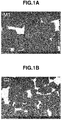
- FIGS. 1A and 1B illustrate a scanning electron micrograph (reflected electron image) within 100 ⁇ m from the surface of the magnet bodies of M1 and C1.
- a layer bright in contrast is observed in the vicinity of the outer shell in some crystal grains. This is because a part of R is substituted with Tb in a part of the surface layer portion of a R 2 Fe 14 B crystal grain.
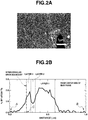
- FIGS. 2A and 2B illustrate a scanning electron micrograph of a field of view different from that of FIG. 1A and a concentration profile of Tb at a line segment AB marked in the photograph.
- TEM-EDS is used to measure a Tb concentration profile, and a sample piece at that time is rotated so that a sample piece thickness direction of an interface at a intergranular grain boundary is parallel to an irradiation direction of an electron beam.
- Tb is not present at the inner center side of the main phase particle, toward the outer shell, a layer having high Tb concentration, a layer having lower Tb concentration than that, and a layer having high Tb concentration again on the outermost side are recognized.
- the Tb concentration profile in the particle on the right side (B side) of the photograph including the line segment BC corresponds to the multiple (in this Example, triple) layers in the present invention. That is, there is a region where the Tb concentration is high from the grain boundary side, and then there is a region where the Tb concentration is low in the form of a minimum. A region with high Tb concentration can be observed inside the region in a form of maximum.
- the concentration profile illustrated in FIG. 2B in these triple layers, the Tb concentration is changed at a change rate of, by at%, 1 %/nm or less in any case where the Tb concentration is increased or decreased.
- a concentration profile of a particle on the left side (A side) of the photograph containing line segment AC is decreased monotonously from the particle surface as illustrated in FIG. 2B , and is a common concentration profile often observed in the magnet body of after the grain boundary diffusion treatment in the related art.
- FIGS. 2A and 2B in the magnet according to the present invention, an aspect that the triple layers are present in a region of another particle facing the region where the above-described triple layers are observed via the grain boundary between the two particles is not observed.
- FIGS. 3A and 3B illustrate a transmission electron micrograph ( FIG. 3A ) of the oxide particle and the Tb concentration profile at the line segment DE in the photograph ( FIG. 3B ) observed within 300 ⁇ m from the surface of the magnet body. As illustrated in FIG.
- the oxide phase present at the triple junction inside the M1 magnet exhibits a smooth shape without corners, and the presence of multiple (in this Example, triple) layers consisting of, toward the outer shell from the center, a layer A having a high Tb concentration, a layer B having a lower Tb concentration than that of the layer A, and a layer C having a high Tb concentration again on the outermost side is recognized.
- the concentration profile illustrated in FIG. 3B in these triple layers A to C, the Tb concentration is changed at a change rate of, by at%, 1%/nm or less in any case where the Tb concentration is increased or decreased.
- the magnetic properties (coercivity, residual magnetic flux density, and (BH) max) of the above-described magnet bodies M1, P1, and C1 were measured. The results are indicated in Table 1. As indicated in Table 1, compared with the coercivity of the magnet (P1) which is not subjected to the diffusion treatment, an enhancement in the coercivity of 950 kAm -1 for the magnet M1 according to the present invention is recognized. In addition, the decrease in the residual magnetic flux density was 5 mT and there was almost no decrease of (BH) max. It is understood that the coercivity enhancing effect of the diffusion treated magnet C1 in the related art is 750 kAm -1 , which does not reach the amount of the coercivity enhanced in the present invention.
- a thin alloy sheet consisting of 13.5 at% of Nd, 1.0 at% of Dy, 3.0 at% of Co, 0.5 at% of Al, 0.2 at% of Cu, 0.1 at% of Zr, 6.0 at% of B, and the balance of Fe was obtained by a strip casting method in which Nd, Dy, Co, Al, Fe, Cu, and Zr metal with a purity of 99% by weight or more and ferroboron were melted at a high frequency in an Ar atmosphere, and the molten metal was poured into a single copper roll. After exposing this alloy to 0.11 MPa of hydrogen at room temperature to occlude hydrogen, and then heated to 500°C to partially release hydrogen while evacuating, cooled, and sieved to make a coarse powder having 50 mesh or less.
- the above coarse powder was finely pulverized to a mass median particle diameter of 3.0 ⁇ m by a jet mill using a high pressure nitrogen gas.
- the obtained fine powder was formed into a block at a pressure of about 100 MPa while being oriented in a magnetic field of 1.2 MA/m under a nitrogen atmosphere.
- the formed body was put into a sintering furnace in an Ar atmosphere, and sintered at 1,040°C for 2 hours to prepare a sintered magnet block.
- This sintered magnet block was ground with a diamond cutter to a dimension of 12 ⁇ 12 ⁇ 5 mm in thickness (direction of orientation), then washed with an alkaline solution, pure water, nitric acid, and pure water in this order, and dried so as to obtain a sintered magnet body.
- the above-described sintered magnet body was immersed for 30 seconds into a suspension in which a terbium oxide powder was mixed with ethanol at a weight fraction of 50% while applying ultrasonic waves.
- the average particle diameter of the terbium oxide powder was 0.3 ⁇ m.
- the magnet body pulled up from the suspension was dried for about 1 minute by hot air of a drier. Thereafter, the magnet body covered with terbium oxide was subjected to the first diffusion treatment under the condition of 920°C for 10 hours in an Ar atmosphere.
- the magnet taken out of the furnace was immersed for 30 seconds into a suspension in which a neodymium fluoride powder was mixed with ethanol at a weight fraction of 50% while applying ultrasonic waves.
- the average particle diameter of the neodymium fluoride powder was 3 ⁇ m.
- the magnet pulled up from the suspension was dried for about 1 minute by hot air of a drier. Thereafter, the magnet body covered with neodymium fluoride was subjected to the second diffusion treatment under the condition of 850°C for 10 hours in an Ar atmosphere.
- the magnet taken out of the furnace was immersed for 30 seconds into a suspension in which a terbium fluoride powder was mixed with ethanol at a weight fraction of 50% while applying ultrasonic waves.
- the average particle diameter of the terbium fluoride powder was 5 ⁇ m.
- the magnet pulled up from the suspension was dried for about 1 minute by hot air of a drier. Thereafter, the magnet body covered with terbium fluoride was subjected to the third diffusion treatment under the condition of 800°C for 20 hours in an Ar atmosphere.
- the magnet body subjected to the diffusion treatment three times was further subjected to an ageing treatment in which a heat treatment was performed at 500°C for 1 hour in vacuum and quenched, so as to obtain a sintered magnet body of the present invention.
- This sintered magnet body is set as a magnet body M2 (Example 2).
- a magnet body P2 (Comparative Example 3) which was subjected to only the ageing treatment without the diffusion treatment
- a magnet body C2 (Comparative Example 4) which was subjected to only the first diffusion treatment and the ageing treatment were also prepared.
- FIG. 4A illustrates a scanning electron micrograph (reflected electron image) within 100 ⁇ m from the surface of the magnet body of M2, and FIG. 4B illustrates the concentration profile of Tb at a line segment FG marked in the photograph.
- the measurement of the Tb concentration profile is the same as that in Example 1. As illustrated in FIGS.
- Tb is not present at the inner center side of the main phase particle, toward the outer shell, a layer having high Tb concentration, a layer having lower Tb concentration than that, and a layer having high Tb concentration again on the outermost side are recognized, and assuming that a point of intersection with the intergranular grain boundary on the line segment FG is set as H, the Tb concentration profile in the particle on the left side of the photograph including the line segment FH corresponds to the multiple (in this Example, triple) layers in the present invention similar to Example 1.
- the magnetic properties (coercivity, residual magnetic flux density, and (BH) max) of the above-described magnet bodies M2, P2, and C2 were measured. The results are indicated in Table 1. As indicated in Table 1, compared with the coercivity of the magnet (P2) which is not subjected to the diffusion treatment, an enhancement in the coercivity of 850 kAm -1 for the magnet M2 according to the present invention is recognized. In addition, the decrease in the residual magnetic flux density was 3 mT and there was almost no decrease of (BH) max. It is understood that the coercivity enhancing effect of the diffusion treated magnet C1 in the related art is 750 kAm -1 , which does not reach the amount of the coercivity enhanced in the present invention.
- a thin alloy sheet consisting of 13.5 at% of Nd, 0.5 at% of Tb, 1.0 at% of Co, 0.2 at% of Al, 0.2 at% of Cu, 0.1 at% of Zr, 0.1 at% of Ga, 5.8 at% of B, and the balance of Fe was obtained by a strip casting method in which Nd, Dy, Co, Al, Fe, Cu, Zr, and Ga metal with a purity of 99% by weight or more and ferroboron were melted at a high frequency in an Ar atmosphere, and the molten metal was poured into a single copper roll. After exposing this alloy to 0.11 MPa of hydrogen at room temperature to occlude hydrogen, and then heated to 500°C to partially release hydrogen while evacuating, cooled, and sieved to make a coarse powder having 50 mesh or less.
- the above coarse powder was finely pulverized to a mass median particle diameter of 2.5 ⁇ m by a jet mill using a high pressure nitrogen gas.
- the obtained fine powder was formed into a block at a pressure of about 100 MPa while being oriented in a magnetic field of 1.2 MA/m under a nitrogen atmosphere.
- the formed body was put into a sintering furnace in an Ar atmosphere, and sintered at 1,030°C for 2 hours to prepare a sintered magnet block.
- This sintered magnet block was ground with a diamond cutter to a dimension of 7 ⁇ 7 ⁇ 6 mm in thickness (direction of orientation), then washed with an alkaline solution, pure water, nitric acid, and pure water in this order, and dried so as to obtain a sintered magnet body.
- the above-described sintered magnet body was immersed for 30 seconds into a suspension in which a dysprosium oxide powder was mixed with pure water at a weight fraction of 50% while applying ultrasonic waves.
- the average particle diameter of the dysprosium oxide powder was 0.25 ⁇ m.
- the magnet body pulled up from the suspension was dried for about 2 minutes by hot air of a drier. Thereafter, the magnet body covered with dysprosium oxide was subjected to the first diffusion treatment under the condition of 850°C for 20 hours in an Ar atmosphere.
- the magnet taken out of the furnace was immersed for 30 seconds into a suspension in which a neodymium hydroxide powder was mixed with pure water at a weight fraction of 50% while applying ultrasonic waves.
- the average particle diameter of the neodymium hydroxide powder was 0.4 ⁇ m.
- the magnet pulled up from the suspension was dried for about 2 minutes by hot air of a drier. Thereafter, the magnet body covered with neodymium hydroxide was subjected to the second diffusion treatment under the condition of 800°C for 20 hours in an Ar atmosphere.
- the magnet taken out of the furnace was immersed for 30 seconds into a suspension of dysprosium oxide and pure water used in the first diffusion treatment while applying ultrasonic waves.
- the magnet pulled up from the suspension was dried for about 2 minutes by hot air of a drier.
- the magnet body covered with dysprosium oxide was subjected to the third diffusion treatment under the condition of 800°C for 30 hours in an Ar atmosphere.
- the magnet body subjected to the diffusion treatment three times was further subjected to an ageing treatment in which a heat treatment was performed at 500°C for 1 hour in vacuum and quenched, so as to obtain a sintered magnet body of the present invention.
- This sintered magnet body is set as a magnet body M3 (Example 3).
- a magnet body P3 (Comparative Example 5) which was subjected to only the ageing treatment without the diffusion treatment
- a magnet body C3 (Comparative Example 6) which was subjected to only the first diffusion treatment and the ageing treatment were also prepared.
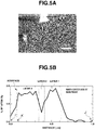
- FIG. 5A illustrates a scanning electron micrograph (reflected electron image) within 100 ⁇ m from the surface of the magnet body of M3, and FIG. 5B illustrates the concentration profile of Dy at a line segment IJ marked in the photograph.
- the measurement of the Dy concentration profile is the same as that in Example 1. As illustrated in FIGS.
- Dy is not present at the inner center side of the main phase particle, toward the outer shell, a layer having high Dy concentration, a layer having lower Dy concentration than that, and a layer having high Dy concentration again on the outermost side are recognized, and assuming that a point of intersection with the intergranular grain boundary on the line segment IJ is set as K, the Dy concentration profile in the particle on the right side of the photograph including the line segment JK corresponds to the multiple (in this Example, triple) layers in the present invention similar to the Tb concentration profile in Examples 1 and 2.
- the magnetic properties (coercivity, residual magnetic flux density, and (BH) max) of the above-described magnet bodies M3, P3, and C3 were measured. The results are indicated in Table 1. As indicated in Table 1, compared with the coercivity of the magnet (P3) which is not subjected to the diffusion treatment, an enhancement in the coercivity of 620 kAm -1 for the magnet body M3 according to the present invention is recognized. Note that, while Tb is diffused in Examples 1 and 2, Dy is diffused in this Example, and thus the amount of the coercivity enhanced is smaller than that in Examples 1 and 2. In addition, the decrease in the residual magnetic flux density was 7 mT and there was almost no decrease of (BH) max. It is understood that the coercivity enhancing effect of the diffusion treated magnet C3 in the related art is 410 kAm -1 , which does not reach the amount of the coercivity enhanced in the present invention.
- the rare earth sintered magnet of the present invention having multiple layers in the main phase particle, and also multiple layers in the oxide phase can exhibit high magnetic properties, and according to the present invention, it was confirmed that an R-Fe-B-based sintered magnet having high performance and capable of reducing the amount of Tb or Dy used can be obtained.
Landscapes
- Engineering & Computer Science (AREA)
- Power Engineering (AREA)
- Chemical & Material Sciences (AREA)
- Crystallography & Structural Chemistry (AREA)
- Inorganic Chemistry (AREA)
- Manufacturing & Machinery (AREA)
- Environmental & Geological Engineering (AREA)
- Metallurgy (AREA)
- Mechanical Engineering (AREA)
- Organic Chemistry (AREA)
- Physics & Mathematics (AREA)
- Electromagnetism (AREA)
- Dispersion Chemistry (AREA)
- Materials Engineering (AREA)
- Hard Magnetic Materials (AREA)
- Manufacturing Cores, Coils, And Magnets (AREA)
Claims (10)
- Gesinterter Seltenerdmagnet, der ein gesinterter Magnetkörper ist, der im Wesentlichen aus einer R1 aR2 bTcMdBe-Zusammensetzung besteht, wobei R1 wenigstens ein Element ist, das aus Seltenerdelementen einschließlich Sc und Y ausgewählt ist, und mit Ausnahme von Tb und Dy, R2 ein oder zwei Elemente ist, die aus Tb und Dy ausgewählt sind, T Fe oder Fe und Co ist, M wenigstens ein Element ist, das aus der Gruppe ausgewählt ist, die aus Al, Cu, Zn, In, Si, P, S, Ti, V, Cr, Mn, Ni, Ga, Ge, Zr, Nb, Mo, Pd, Ag, Cd, Sn, Sb, Hf, Ta und W besteht, B Bor ist, a bis e, in At.-% der Legierungszusammensetzung, 12 ≤ a + b ≤ 17, 0,01 ≤ d ≤ 11 und 3 ≤ e ≤ 15 erfüllen, und der Rest c ist, wobei der Magnet ein Hauptphasenpartikel mit einer tetragonalen Nd2Fe14B-Struktur umfasst, wobei ein mehrschichtiges Hauptphasenpartikel mehrere Schichten aufweist, einschließlich einer Schicht 1, die eine R2-Konzentration aufweist, die durch At.-% dargestellt ist, die höher als die eines Zentrums des Partikels ist, einer Schicht 2, die auf der Außenseite der Schicht 1 gebildet ist und eine R2-Konzentration aufweist, die niedriger als die der Schicht 1 ist, und einer Schicht 3, die auf der Außenseite der Schicht 2 gebildet ist und eine R2-Konzentration aufweist, die höher als die der Schicht 2 ist, wenigstens in einem Abschnitt in der Nähe einer Oberfläche des Hauptphasenpartikels innerhalb von wenigstens 500 µm von einer Oberfläche des gesinterten Magnetkörpers vorhanden ist.
- Gesinterter Seltenerdmagnet nach Anspruch 1, wobei das mehrschichtige Hauptphasenpartikel in jedem Fall mit einer Änderungsrate von, in At.-%, höchstens 1 %/nm verändert wird, wenn die R2-Konzentration von dem Zentrum des Partikels zu der Schicht 1, der Schicht 2 und der Schicht 3 erhöht oder verringert wird.
- Gesinterter Seltenerdmagnet nach Anspruch 1 oder 2, wobei Werte, die durch Subtrahieren einer durchschnittlichen R2-Konzentration des Zentrums des Partikels von den jeweiligen R2-Konzentrationen der Schicht 1, der Schicht 2 und der Schicht 3, die in dem mehrschichtigen Hauptphasenpartikel beinhaltet sind, als C1, C2 und C3 in At.-% gesetzt werden, wenn ein Maximalwert von C1 als C1max gesetzt wird, ein Minimalwert von C2 als C2min gesetzt wird, ein Maximalwert von C3 als C3max gesetzt wird und ein kleinerer Wert von C1max und C3max als Cmax gesetzt wird, C1max wenigstens 0,5 % und höchstens 8 % beträgt und C2min höchstens 70 % von Cmax beträgt, und C3max wenigstens 0,5 % und höchstens 8 % beträgt, und C1, C2, und C3 (C2min + Cmax)/2 < C1 ≤ C1max, C2min ≤ C2 ≤ (C2min + Cmax)/2 beziehungswiese (C2min + Cmax)/2 < C3 ≤ C3max erfüllen.
- Gesinterter Seltenerdmagnet nach einem der Ansprüche 1 bis 3, wobei eine Dicke jeder der Schichten 1 bis 3 0,02 bis 1,5 µm beträgt.
- Gesinterter Seltenerdmagnet nach einem der Ansprüche 1 bis 4, wobei in einem Partikel, das über eine Kristallkorngrenzphase an das mehrschichtige Hauptphasenpartikel angrenzt, die mehreren Schichten nicht in einem Bereich vorhanden sind, der einem Bereich gegenüberliegt, in dem die mehreren Schichten des mehrschichtigen Hauptphasenpartikels vorhanden sind.
- Gesinterter Seltenerdmagnet nach einem der Ansprüche 1 bis 5, wobei ein Oxidpartikel einschließlich R1 und R2, das eine Form ohne eine Ecke aufweist, in wenigstens einem Teil eines Dreifachübergangs vorhanden ist, der von drei oder mehr der Hauptphasenpartikel umgeben ist, und wenigstens ein Teil des Oxidpartikels ein mehrschichtiges Oxidpartikel ist, die mehrere Schichten aufweist, das eine Schicht A, die eine R2-Konzentration aufweist, die durch At.-% dargestellt wird, die höher als die eines Zentrums des Partikels ist, eine Schicht B, die auf dem Äußeren der Schicht A gebildet ist und eine R2-Konzentration aufweist, die niedriger als die der Schicht A ist, und eine Schicht C einschließt, die auf dem Äußeren der Schicht B gebildet ist und eine R2-Konzentration aufweist, die höher als die der Schicht B ist.
- Gesinterter Seltenerdmagnet nach Anspruch 6, wobei das mehrschichtige Oxidpartikel in jedem Fall bei einer Änderungsrate von, in At.-%, höchstens 1 %/nm verändert wird, wenn die R2-Konzentration von dem Zentrum des Partikels zu der Schicht A, der Schicht B und der Schicht C erhöht oder verringert wird.
- Gesinterter Seltenerdmagnet nach Anspruch 6 oder 7, wobei Werte, die durch Subtrahieren einer durchschnittlichen R2-Konzentration des Zentrums des Partikels von den jeweiligen R2-Konzentrationen der Schicht A, der Schicht B und der Schicht C, die in dem mehrschichtigen Oxidpartikel eingeschlossen sind, als XA, XB und XC in At.-% gesetzt sind, wenn ein Maximalwert von XA als XAmax gesetzt wird, ein Minimalwert von XB als XBmin gesetzt wird, ein Maximalwert von XC als XCmax gesetzt wird und ein kleinerer Wert von XAmax und XCmax als Xmax gesetzt wird, XAmax wenigstens 1 % und höchstens 20 % beträgt, XBmin höchstens 70 % von Xmax beträgt, und XCmax wenigstens 1.% und höchstens 20 % beträgt und XA, XB und XC (XBmin + Xmax)/2 < XA ≤ XAmax, XBmin ≤ XB ≤ (XBmin + Xmax)/2 beziehungsweise (XBmin + Xmax)/2 < XC ≤ XCmax erfüllen.
- Gesinterter Seltenerdmagnet nach einem der Ansprüche 6 bis 8, wobei die Dicke jeder der Schichten A bis C 0,05 bis 1 µm beträgt.
- Gesinterter Seltenerdmagnet nach einem der Ansprüche 6 bis 9, wobei ein oder zwei oder mehr Elemente, die aus der Gruppe ausgewählt sind, die aus C, N und F besteht, in dem Oxidpartikel enthalten sind.
Applications Claiming Priority (1)
| Application Number | Priority Date | Filing Date | Title |
|---|---|---|---|
| JP2018189121A JP7196514B2 (ja) | 2018-10-04 | 2018-10-04 | 希土類焼結磁石 |
Publications (2)
| Publication Number | Publication Date |
|---|---|
| EP3633696A1 EP3633696A1 (de) | 2020-04-08 |
| EP3633696B1 true EP3633696B1 (de) | 2021-01-27 |
Family
ID=67999581
Family Applications (1)
| Application Number | Title | Priority Date | Filing Date |
|---|---|---|---|
| EP19198188.5A Active EP3633696B1 (de) | 2018-10-04 | 2019-09-19 | Gesinterter seltenerd-magnet |
Country Status (5)
| Country | Link |
|---|---|
| US (1) | US11798716B2 (de) |
| EP (1) | EP3633696B1 (de) |
| JP (1) | JP7196514B2 (de) |
| KR (1) | KR102660624B1 (de) |
| CN (1) | CN111009367B (de) |
Families Citing this family (4)
| Publication number | Priority date | Publication date | Assignee | Title |
|---|---|---|---|---|
| JP7298533B2 (ja) * | 2020-04-21 | 2023-06-27 | トヨタ自動車株式会社 | 希土類磁石及びその製造方法 |
| CN111916284B (zh) * | 2020-08-08 | 2022-05-24 | 烟台首钢磁性材料股份有限公司 | 一种高矫顽力烧结钕铁硼磁体的制备方法 |
| JP7585783B2 (ja) | 2020-12-28 | 2024-11-19 | トヨタ自動車株式会社 | 希土類磁石及びその製造方法 |
| CN113593873B (zh) * | 2021-06-25 | 2024-09-17 | 京磁材料科技股份有限公司 | 一种高矫顽力混合稀土永磁材料及其制备方法 |
Family Cites Families (21)
| Publication number | Priority date | Publication date | Assignee | Title |
|---|---|---|---|---|
| JPS5726902A (en) * | 1980-07-25 | 1982-02-13 | Hitachi Ltd | Fet oscillation circuit |
| JP2853838B2 (ja) | 1991-06-04 | 1999-02-03 | 信越化学工業株式会社 | 希土類永久磁石の製造方法 |
| RU2367045C2 (ru) | 2004-10-19 | 2009-09-10 | Син-Эцу Кемикал Ко., Лтд. | Получение материала редкоземельного постоянного магнита |
| CN100501884C (zh) * | 2005-03-14 | 2009-06-17 | Tdk株式会社 | R-t-b系烧结磁体 |
| TWI364765B (en) * | 2005-03-23 | 2012-05-21 | Shinetsu Chemical Co | Rare earth permanent magnet |
| EP1993112B1 (de) | 2006-03-03 | 2015-08-12 | Hitachi Metals, Ltd. | R-Fe-B SELTENERDGESINTERTER MAGNET UND HERSTELLUNGSVERFAHREN DAFÜR |
| KR101425828B1 (ko) | 2006-08-23 | 2014-08-05 | 가부시키가이샤 알박 | 영구자석 및 영구자석의 제조방법 |
| JP4840606B2 (ja) | 2006-11-17 | 2011-12-21 | 信越化学工業株式会社 | 希土類永久磁石の製造方法 |
| KR101165935B1 (ko) | 2007-03-20 | 2012-07-19 | 스미토모 베이클리트 컴퍼니 리미티드 | 적층판의 제조 방법 및 적층판 |
| WO2009004794A1 (ja) * | 2007-07-02 | 2009-01-08 | Hitachi Metals, Ltd. | R-Fe-B系希土類焼結磁石およびその製造方法 |
| JP5256851B2 (ja) | 2008-05-29 | 2013-08-07 | Tdk株式会社 | 磁石の製造方法 |
| JP4902677B2 (ja) * | 2009-02-02 | 2012-03-21 | 株式会社日立製作所 | 希土類磁石 |
| JP5218368B2 (ja) | 2009-10-10 | 2013-06-26 | 株式会社豊田中央研究所 | 希土類磁石材およびその製造方法 |
| EP2595163B1 (de) * | 2010-07-12 | 2019-05-29 | Hitachi Metals, Ltd. | Verfahren zur herstellung von sintermagneten auf rtb-basis |
| DE112012002220T5 (de) * | 2011-05-25 | 2014-07-17 | Tdk Corp. | Gesinterte Selten-Erd-Magnete, Verfahren zur Herstellung derselben, und eine rotierende Maschine |
| JP5572673B2 (ja) * | 2011-07-08 | 2014-08-13 | 昭和電工株式会社 | R−t−b系希土類焼結磁石用合金、r−t−b系希土類焼結磁石用合金の製造方法、r−t−b系希土類焼結磁石用合金材料、r−t−b系希土類焼結磁石、r−t−b系希土類焼結磁石の製造方法およびモーター |
| JP5392440B1 (ja) * | 2012-02-13 | 2014-01-22 | Tdk株式会社 | R−t−b系焼結磁石 |
| WO2013146073A1 (ja) * | 2012-03-30 | 2013-10-03 | 日立金属株式会社 | R-t-b系焼結磁石の製造方法 |
| PH12013000103B1 (en) * | 2012-04-11 | 2015-09-07 | Shinetsu Chemical Co | Rare earth sintered magnet and making method |
| JP6645219B2 (ja) * | 2016-02-01 | 2020-02-14 | Tdk株式会社 | R−t−b系焼結磁石用合金、及びr−t−b系焼結磁石 |
| JP2018189121A (ja) | 2017-04-28 | 2018-11-29 | 株式会社ミマキエンジニアリング | 筒体の補強構造、ガイドローラ、及び搬送機構 |
-
2018
- 2018-10-04 JP JP2018189121A patent/JP7196514B2/ja active Active
-
2019
- 2019-09-19 EP EP19198188.5A patent/EP3633696B1/de active Active
- 2019-09-27 CN CN201910922280.4A patent/CN111009367B/zh active Active
- 2019-10-03 US US16/592,240 patent/US11798716B2/en active Active
- 2019-10-04 KR KR1020190123079A patent/KR102660624B1/ko active Active
Non-Patent Citations (1)
| Title |
|---|
| None * |
Also Published As
| Publication number | Publication date |
|---|---|
| EP3633696A1 (de) | 2020-04-08 |
| US11798716B2 (en) | 2023-10-24 |
| JP7196514B2 (ja) | 2022-12-27 |
| CN111009367A (zh) | 2020-04-14 |
| US20200111591A1 (en) | 2020-04-09 |
| KR20200038874A (ko) | 2020-04-14 |
| CN111009367B (zh) | 2024-08-02 |
| JP2020057734A (ja) | 2020-04-09 |
| KR102660624B1 (ko) | 2024-04-25 |
Similar Documents
| Publication | Publication Date | Title |
|---|---|---|
| EP1845539B1 (de) | Verfahren zur Herstellung von einem Material für Dauermagnete aus seltenen Erden | |
| EP1890301B1 (de) | Verfahren zur herstellung von seltenerdpermanentmagnetmaterial | |
| JP4450239B2 (ja) | 希土類永久磁石材料及びその製造方法 | |
| RU2417139C2 (ru) | Способ приготовления материала редкоземельного постоянного магнита | |
| CN100520992C (zh) | 稀土永磁体 | |
| EP1845536B1 (de) | Verfahren zur Herstellung von einem Material für Dauermagnete aus seltenen Erden | |
| JP6090589B2 (ja) | 希土類永久磁石の製造方法 | |
| EP3633696B1 (de) | Gesinterter seltenerd-magnet | |
| KR20150052153A (ko) | 희토류 영구자석의 제조 방법 | |
| JP2025503524A (ja) | ネオジム鉄ボロン磁石及びその製造方法並びに応用 | |
| JP4702549B2 (ja) | 希土類永久磁石 | |
| WO2014034849A1 (ja) | 希土類永久磁石の製造方法 |
Legal Events
| Date | Code | Title | Description |
|---|---|---|---|
| PUAI | Public reference made under article 153(3) epc to a published international application that has entered the european phase |
Free format text: ORIGINAL CODE: 0009012 |
|
| STAA | Information on the status of an ep patent application or granted ep patent |
Free format text: STATUS: THE APPLICATION HAS BEEN PUBLISHED |
|
| AK | Designated contracting states |
Kind code of ref document: A1 Designated state(s): AL AT BE BG CH CY CZ DE DK EE ES FI FR GB GR HR HU IE IS IT LI LT LU LV MC MK MT NL NO PL PT RO RS SE SI SK SM TR |
|
| AX | Request for extension of the european patent |
Extension state: BA ME |
|
| STAA | Information on the status of an ep patent application or granted ep patent |
Free format text: STATUS: REQUEST FOR EXAMINATION WAS MADE |
|
| 17P | Request for examination filed |
Effective date: 20200706 |
|
| RBV | Designated contracting states (corrected) |
Designated state(s): AL AT BE BG CH CY CZ DE DK EE ES FI FR GB GR HR HU IE IS IT LI LT LU LV MC MK MT NL NO PL PT RO RS SE SI SK SM TR |
|
| GRAP | Despatch of communication of intention to grant a patent |
Free format text: ORIGINAL CODE: EPIDOSNIGR1 |
|
| STAA | Information on the status of an ep patent application or granted ep patent |
Free format text: STATUS: GRANT OF PATENT IS INTENDED |
|
| INTG | Intention to grant announced |
Effective date: 20200924 |
|
| GRAS | Grant fee paid |
Free format text: ORIGINAL CODE: EPIDOSNIGR3 |
|
| GRAA | (expected) grant |
Free format text: ORIGINAL CODE: 0009210 |
|
| STAA | Information on the status of an ep patent application or granted ep patent |
Free format text: STATUS: THE PATENT HAS BEEN GRANTED |
|
| AK | Designated contracting states |
Kind code of ref document: B1 Designated state(s): AL AT BE BG CH CY CZ DE DK EE ES FI FR GB GR HR HU IE IS IT LI LT LU LV MC MK MT NL NO PL PT RO RS SE SI SK SM TR |
|
| REG | Reference to a national code |
Ref country code: GB Ref legal event code: FG4D |
|
| REG | Reference to a national code |
Ref country code: CH Ref legal event code: EP |
|
| REG | Reference to a national code |
Ref country code: AT Ref legal event code: REF Ref document number: 1359093 Country of ref document: AT Kind code of ref document: T Effective date: 20210215 |
|
| REG | Reference to a national code |
Ref country code: IE Ref legal event code: FG4D |
|
| REG | Reference to a national code |
Ref country code: DE Ref legal event code: R096 Ref document number: 602019002384 Country of ref document: DE |
|
| REG | Reference to a national code |
Ref country code: NL Ref legal event code: MP Effective date: 20210127 |
|
| REG | Reference to a national code |
Ref country code: LT Ref legal event code: MG9D |
|
| REG | Reference to a national code |
Ref country code: AT Ref legal event code: MK05 Ref document number: 1359093 Country of ref document: AT Kind code of ref document: T Effective date: 20210127 |
|
| PG25 | Lapsed in a contracting state [announced via postgrant information from national office to epo] |
Ref country code: FI Free format text: LAPSE BECAUSE OF FAILURE TO SUBMIT A TRANSLATION OF THE DESCRIPTION OR TO PAY THE FEE WITHIN THE PRESCRIBED TIME-LIMIT Effective date: 20210127 Ref country code: GR Free format text: LAPSE BECAUSE OF FAILURE TO SUBMIT A TRANSLATION OF THE DESCRIPTION OR TO PAY THE FEE WITHIN THE PRESCRIBED TIME-LIMIT Effective date: 20210428 Ref country code: BG Free format text: LAPSE BECAUSE OF FAILURE TO SUBMIT A TRANSLATION OF THE DESCRIPTION OR TO PAY THE FEE WITHIN THE PRESCRIBED TIME-LIMIT Effective date: 20210427 Ref country code: HR Free format text: LAPSE BECAUSE OF FAILURE TO SUBMIT A TRANSLATION OF THE DESCRIPTION OR TO PAY THE FEE WITHIN THE PRESCRIBED TIME-LIMIT Effective date: 20210127 Ref country code: NO Free format text: LAPSE BECAUSE OF FAILURE TO SUBMIT A TRANSLATION OF THE DESCRIPTION OR TO PAY THE FEE WITHIN THE PRESCRIBED TIME-LIMIT Effective date: 20210427 Ref country code: PT Free format text: LAPSE BECAUSE OF FAILURE TO SUBMIT A TRANSLATION OF THE DESCRIPTION OR TO PAY THE FEE WITHIN THE PRESCRIBED TIME-LIMIT Effective date: 20210527 Ref country code: LT Free format text: LAPSE BECAUSE OF FAILURE TO SUBMIT A TRANSLATION OF THE DESCRIPTION OR TO PAY THE FEE WITHIN THE PRESCRIBED TIME-LIMIT Effective date: 20210127 |
|
| PG25 | Lapsed in a contracting state [announced via postgrant information from national office to epo] |
Ref country code: RS Free format text: LAPSE BECAUSE OF FAILURE TO SUBMIT A TRANSLATION OF THE DESCRIPTION OR TO PAY THE FEE WITHIN THE PRESCRIBED TIME-LIMIT Effective date: 20210127 Ref country code: SE Free format text: LAPSE BECAUSE OF FAILURE TO SUBMIT A TRANSLATION OF THE DESCRIPTION OR TO PAY THE FEE WITHIN THE PRESCRIBED TIME-LIMIT Effective date: 20210127 Ref country code: AT Free format text: LAPSE BECAUSE OF FAILURE TO SUBMIT A TRANSLATION OF THE DESCRIPTION OR TO PAY THE FEE WITHIN THE PRESCRIBED TIME-LIMIT Effective date: 20210127 Ref country code: LV Free format text: LAPSE BECAUSE OF FAILURE TO SUBMIT A TRANSLATION OF THE DESCRIPTION OR TO PAY THE FEE WITHIN THE PRESCRIBED TIME-LIMIT Effective date: 20210127 Ref country code: PL Free format text: LAPSE BECAUSE OF FAILURE TO SUBMIT A TRANSLATION OF THE DESCRIPTION OR TO PAY THE FEE WITHIN THE PRESCRIBED TIME-LIMIT Effective date: 20210127 |
|
| PG25 | Lapsed in a contracting state [announced via postgrant information from national office to epo] |
Ref country code: IS Free format text: LAPSE BECAUSE OF FAILURE TO SUBMIT A TRANSLATION OF THE DESCRIPTION OR TO PAY THE FEE WITHIN THE PRESCRIBED TIME-LIMIT Effective date: 20210527 |
|
| REG | Reference to a national code |
Ref country code: DE Ref legal event code: R097 Ref document number: 602019002384 Country of ref document: DE |
|
| PG25 | Lapsed in a contracting state [announced via postgrant information from national office to epo] |
Ref country code: SM Free format text: LAPSE BECAUSE OF FAILURE TO SUBMIT A TRANSLATION OF THE DESCRIPTION OR TO PAY THE FEE WITHIN THE PRESCRIBED TIME-LIMIT Effective date: 20210127 Ref country code: CZ Free format text: LAPSE BECAUSE OF FAILURE TO SUBMIT A TRANSLATION OF THE DESCRIPTION OR TO PAY THE FEE WITHIN THE PRESCRIBED TIME-LIMIT Effective date: 20210127 Ref country code: EE Free format text: LAPSE BECAUSE OF FAILURE TO SUBMIT A TRANSLATION OF THE DESCRIPTION OR TO PAY THE FEE WITHIN THE PRESCRIBED TIME-LIMIT Effective date: 20210127 |
|
| PG25 | Lapsed in a contracting state [announced via postgrant information from national office to epo] |
Ref country code: DK Free format text: LAPSE BECAUSE OF FAILURE TO SUBMIT A TRANSLATION OF THE DESCRIPTION OR TO PAY THE FEE WITHIN THE PRESCRIBED TIME-LIMIT Effective date: 20210127 Ref country code: RO Free format text: LAPSE BECAUSE OF FAILURE TO SUBMIT A TRANSLATION OF THE DESCRIPTION OR TO PAY THE FEE WITHIN THE PRESCRIBED TIME-LIMIT Effective date: 20210127 Ref country code: SK Free format text: LAPSE BECAUSE OF FAILURE TO SUBMIT A TRANSLATION OF THE DESCRIPTION OR TO PAY THE FEE WITHIN THE PRESCRIBED TIME-LIMIT Effective date: 20210127 |
|
| PLBE | No opposition filed within time limit |
Free format text: ORIGINAL CODE: 0009261 |
|
| STAA | Information on the status of an ep patent application or granted ep patent |
Free format text: STATUS: NO OPPOSITION FILED WITHIN TIME LIMIT |
|
| 26N | No opposition filed |
Effective date: 20211028 |
|
| PG25 | Lapsed in a contracting state [announced via postgrant information from national office to epo] |
Ref country code: ES Free format text: LAPSE BECAUSE OF FAILURE TO SUBMIT A TRANSLATION OF THE DESCRIPTION OR TO PAY THE FEE WITHIN THE PRESCRIBED TIME-LIMIT Effective date: 20210127 Ref country code: AL Free format text: LAPSE BECAUSE OF FAILURE TO SUBMIT A TRANSLATION OF THE DESCRIPTION OR TO PAY THE FEE WITHIN THE PRESCRIBED TIME-LIMIT Effective date: 20210127 |
|
| PG25 | Lapsed in a contracting state [announced via postgrant information from national office to epo] |
Ref country code: SI Free format text: LAPSE BECAUSE OF FAILURE TO SUBMIT A TRANSLATION OF THE DESCRIPTION OR TO PAY THE FEE WITHIN THE PRESCRIBED TIME-LIMIT Effective date: 20210127 |
|
| PG25 | Lapsed in a contracting state [announced via postgrant information from national office to epo] |
Ref country code: IT Free format text: LAPSE BECAUSE OF FAILURE TO SUBMIT A TRANSLATION OF THE DESCRIPTION OR TO PAY THE FEE WITHIN THE PRESCRIBED TIME-LIMIT Effective date: 20210127 |
|
| REG | Reference to a national code |
Ref country code: BE Ref legal event code: MM Effective date: 20210930 |
|
| PG25 | Lapsed in a contracting state [announced via postgrant information from national office to epo] |
Ref country code: IS Free format text: LAPSE BECAUSE OF FAILURE TO SUBMIT A TRANSLATION OF THE DESCRIPTION OR TO PAY THE FEE WITHIN THE PRESCRIBED TIME-LIMIT Effective date: 20210527 Ref country code: MC Free format text: LAPSE BECAUSE OF FAILURE TO SUBMIT A TRANSLATION OF THE DESCRIPTION OR TO PAY THE FEE WITHIN THE PRESCRIBED TIME-LIMIT Effective date: 20210127 |
|
| PG25 | Lapsed in a contracting state [announced via postgrant information from national office to epo] |
Ref country code: LU Free format text: LAPSE BECAUSE OF NON-PAYMENT OF DUE FEES Effective date: 20210919 Ref country code: IE Free format text: LAPSE BECAUSE OF NON-PAYMENT OF DUE FEES Effective date: 20210919 Ref country code: FR Free format text: LAPSE BECAUSE OF NON-PAYMENT OF DUE FEES Effective date: 20210930 Ref country code: BE Free format text: LAPSE BECAUSE OF NON-PAYMENT OF DUE FEES Effective date: 20210930 |
|
| REG | Reference to a national code |
Ref country code: CH Ref legal event code: PL |
|
| PG25 | Lapsed in a contracting state [announced via postgrant information from national office to epo] |
Ref country code: NL Free format text: LAPSE BECAUSE OF NON-PAYMENT OF DUE FEES Effective date: 20210127 Ref country code: CY Free format text: LAPSE BECAUSE OF FAILURE TO SUBMIT A TRANSLATION OF THE DESCRIPTION OR TO PAY THE FEE WITHIN THE PRESCRIBED TIME-LIMIT Effective date: 20210127 |
|
| PG25 | Lapsed in a contracting state [announced via postgrant information from national office to epo] |
Ref country code: LI Free format text: LAPSE BECAUSE OF NON-PAYMENT OF DUE FEES Effective date: 20220930 Ref country code: HU Free format text: LAPSE BECAUSE OF FAILURE TO SUBMIT A TRANSLATION OF THE DESCRIPTION OR TO PAY THE FEE WITHIN THE PRESCRIBED TIME-LIMIT; INVALID AB INITIO Effective date: 20190919 Ref country code: CH Free format text: LAPSE BECAUSE OF NON-PAYMENT OF DUE FEES Effective date: 20220930 |
|
| PG25 | Lapsed in a contracting state [announced via postgrant information from national office to epo] |
Ref country code: MK Free format text: LAPSE BECAUSE OF FAILURE TO SUBMIT A TRANSLATION OF THE DESCRIPTION OR TO PAY THE FEE WITHIN THE PRESCRIBED TIME-LIMIT Effective date: 20210127 |
|
| GBPC | Gb: european patent ceased through non-payment of renewal fee |
Effective date: 20230919 |
|
| PG25 | Lapsed in a contracting state [announced via postgrant information from national office to epo] |
Ref country code: TR Free format text: LAPSE BECAUSE OF FAILURE TO SUBMIT A TRANSLATION OF THE DESCRIPTION OR TO PAY THE FEE WITHIN THE PRESCRIBED TIME-LIMIT Effective date: 20210127 |
|
| PG25 | Lapsed in a contracting state [announced via postgrant information from national office to epo] |
Ref country code: GB Free format text: LAPSE BECAUSE OF NON-PAYMENT OF DUE FEES Effective date: 20230919 |
|
| PG25 | Lapsed in a contracting state [announced via postgrant information from national office to epo] |
Ref country code: GB Free format text: LAPSE BECAUSE OF NON-PAYMENT OF DUE FEES Effective date: 20230919 |
|
| PG25 | Lapsed in a contracting state [announced via postgrant information from national office to epo] |
Ref country code: MT Free format text: LAPSE BECAUSE OF FAILURE TO SUBMIT A TRANSLATION OF THE DESCRIPTION OR TO PAY THE FEE WITHIN THE PRESCRIBED TIME-LIMIT Effective date: 20210127 |
|
| PGFP | Annual fee paid to national office [announced via postgrant information from national office to epo] |
Ref country code: DE Payment date: 20250919 Year of fee payment: 7 |