EP4058709B1 - Stauchrohrverbindungssysteme und verfahren - Google Patents
Stauchrohrverbindungssysteme und verfahren Download PDFInfo
- Publication number
- EP4058709B1 EP4058709B1 EP20891193.3A EP20891193A EP4058709B1 EP 4058709 B1 EP4058709 B1 EP 4058709B1 EP 20891193 A EP20891193 A EP 20891193A EP 4058709 B1 EP4058709 B1 EP 4058709B1
- Authority
- EP
- European Patent Office
- Prior art keywords
- fitting
- pipe
- swaged
- pipe segment
- layer
- Prior art date
- Legal status (The legal status is an assumption and is not a legal conclusion. Google has not performed a legal analysis and makes no representation as to the accuracy of the status listed.)
- Active
Links
Images


Classifications
-
- F—MECHANICAL ENGINEERING; LIGHTING; HEATING; WEAPONS; BLASTING
- F16—ENGINEERING ELEMENTS AND UNITS; GENERAL MEASURES FOR PRODUCING AND MAINTAINING EFFECTIVE FUNCTIONING OF MACHINES OR INSTALLATIONS; THERMAL INSULATION IN GENERAL
- F16L—PIPES; JOINTS OR FITTINGS FOR PIPES; SUPPORTS FOR PIPES, CABLES OR PROTECTIVE TUBING; MEANS FOR THERMAL INSULATION IN GENERAL
- F16L13/00—Non-disconnectable pipe joints, e.g. soldered, adhesive, or caulked joints
- F16L13/14—Non-disconnectable pipe joints, e.g. soldered, adhesive, or caulked joints made by plastically deforming the material of the pipe, e.g. by flanging, rolling
- F16L13/141—Non-disconnectable pipe joints, e.g. soldered, adhesive, or caulked joints made by plastically deforming the material of the pipe, e.g. by flanging, rolling by crimping or rolling from the outside
- F16L13/142—Non-disconnectable pipe joints, e.g. soldered, adhesive, or caulked joints made by plastically deforming the material of the pipe, e.g. by flanging, rolling by crimping or rolling from the outside with a sealing element inserted into the female part before crimping or rolling
-
- B—PERFORMING OPERATIONS; TRANSPORTING
- B21—MECHANICAL METAL-WORKING WITHOUT ESSENTIALLY REMOVING MATERIAL; PUNCHING METAL
- B21D—WORKING OR PROCESSING OF SHEET METAL OR METAL TUBES, RODS OR PROFILES WITHOUT ESSENTIALLY REMOVING MATERIAL; PUNCHING METAL
- B21D39/00—Application of procedures in order to connect objects or parts, e.g. coating with sheet metal otherwise than by plating; Tube expanders
- B21D39/04—Application of procedures in order to connect objects or parts, e.g. coating with sheet metal otherwise than by plating; Tube expanders of tubes with tubes; of tubes with rods
- B21D39/046—Connecting tubes to tube-like fittings
-
- B—PERFORMING OPERATIONS; TRANSPORTING
- B21—MECHANICAL METAL-WORKING WITHOUT ESSENTIALLY REMOVING MATERIAL; PUNCHING METAL
- B21D—WORKING OR PROCESSING OF SHEET METAL OR METAL TUBES, RODS OR PROFILES WITHOUT ESSENTIALLY REMOVING MATERIAL; PUNCHING METAL
- B21D39/00—Application of procedures in order to connect objects or parts, e.g. coating with sheet metal otherwise than by plating; Tube expanders
- B21D39/08—Tube expanders
- B21D39/20—Tube expanders with mandrels, e.g. expandable
-
- F—MECHANICAL ENGINEERING; LIGHTING; HEATING; WEAPONS; BLASTING
- F16—ENGINEERING ELEMENTS AND UNITS; GENERAL MEASURES FOR PRODUCING AND MAINTAINING EFFECTIVE FUNCTIONING OF MACHINES OR INSTALLATIONS; THERMAL INSULATION IN GENERAL
- F16L—PIPES; JOINTS OR FITTINGS FOR PIPES; SUPPORTS FOR PIPES, CABLES OR PROTECTIVE TUBING; MEANS FOR THERMAL INSULATION IN GENERAL
- F16L33/00—Arrangements for connecting hoses to rigid members; Rigid hose-connectors, i.e. single members engaging both hoses
- F16L33/01—Arrangements for connecting hoses to rigid members; Rigid hose-connectors, i.e. single members engaging both hoses specially adapted for hoses having a multi-layer wall
-
- F—MECHANICAL ENGINEERING; LIGHTING; HEATING; WEAPONS; BLASTING
- F16—ENGINEERING ELEMENTS AND UNITS; GENERAL MEASURES FOR PRODUCING AND MAINTAINING EFFECTIVE FUNCTIONING OF MACHINES OR INSTALLATIONS; THERMAL INSULATION IN GENERAL
- F16L—PIPES; JOINTS OR FITTINGS FOR PIPES; SUPPORTS FOR PIPES, CABLES OR PROTECTIVE TUBING; MEANS FOR THERMAL INSULATION IN GENERAL
- F16L33/00—Arrangements for connecting hoses to rigid members; Rigid hose-connectors, i.e. single members engaging both hoses
- F16L33/20—Undivided rings, sleeves, or like members contracted on the hose or expanded inside the hose by means of tools; Arrangements using such members
- F16L33/207—Undivided rings, sleeves, or like members contracted on the hose or expanded inside the hose by means of tools; Arrangements using such members only a sleeve being contracted on the hose
- F16L33/2071—Undivided rings, sleeves, or like members contracted on the hose or expanded inside the hose by means of tools; Arrangements using such members only a sleeve being contracted on the hose the sleeve being a separate connecting member
- F16L33/2078—Undivided rings, sleeves, or like members contracted on the hose or expanded inside the hose by means of tools; Arrangements using such members only a sleeve being contracted on the hose the sleeve being a separate connecting member connected to the rigid member via an intermediate element
-
- F—MECHANICAL ENGINEERING; LIGHTING; HEATING; WEAPONS; BLASTING
- F16—ENGINEERING ELEMENTS AND UNITS; GENERAL MEASURES FOR PRODUCING AND MAINTAINING EFFECTIVE FUNCTIONING OF MACHINES OR INSTALLATIONS; THERMAL INSULATION IN GENERAL
- F16L—PIPES; JOINTS OR FITTINGS FOR PIPES; SUPPORTS FOR PIPES, CABLES OR PROTECTIVE TUBING; MEANS FOR THERMAL INSULATION IN GENERAL
- F16L11/00—Hoses, i.e. flexible pipes
- F16L11/04—Hoses, i.e. flexible pipes made of rubber or flexible plastics
- F16L11/08—Hoses, i.e. flexible pipes made of rubber or flexible plastics with reinforcements embedded in the wall
- F16L11/081—Hoses, i.e. flexible pipes made of rubber or flexible plastics with reinforcements embedded in the wall comprising one or more layers of a helically wound cord or wire
-
- F—MECHANICAL ENGINEERING; LIGHTING; HEATING; WEAPONS; BLASTING
- F16—ENGINEERING ELEMENTS AND UNITS; GENERAL MEASURES FOR PRODUCING AND MAINTAINING EFFECTIVE FUNCTIONING OF MACHINES OR INSTALLATIONS; THERMAL INSULATION IN GENERAL
- F16L—PIPES; JOINTS OR FITTINGS FOR PIPES; SUPPORTS FOR PIPES, CABLES OR PROTECTIVE TUBING; MEANS FOR THERMAL INSULATION IN GENERAL
- F16L33/00—Arrangements for connecting hoses to rigid members; Rigid hose-connectors, i.e. single members engaging both hoses
- F16L33/28—Arrangements for connecting hoses to rigid members; Rigid hose-connectors, i.e. single members engaging both hoses for hoses with one end terminating in a radial flange or collar
-
- F—MECHANICAL ENGINEERING; LIGHTING; HEATING; WEAPONS; BLASTING
- F16—ENGINEERING ELEMENTS AND UNITS; GENERAL MEASURES FOR PRODUCING AND MAINTAINING EFFECTIVE FUNCTIONING OF MACHINES OR INSTALLATIONS; THERMAL INSULATION IN GENERAL
- F16L—PIPES; JOINTS OR FITTINGS FOR PIPES; SUPPORTS FOR PIPES, CABLES OR PROTECTIVE TUBING; MEANS FOR THERMAL INSULATION IN GENERAL
- F16L39/00—Joints or fittings for double-walled or multi-channel pipes or pipe assemblies
- F16L39/02—Joints or fittings for double-walled or multi-channel pipes or pipe assemblies for hoses
Definitions
- Flexible pipe can be utilized to transport production fluids, such as oil and/or gas and/or water, from one location to another.
- Flexible pipe is generally formed as an assembly of a portion of flexible pipe body and one or more end fittings.
- the end fittings may be used to connect segments of flexible pipe together or to connect them to terminal equipment, such as sub-sea structures or floating facilities. End fittings are important components for terminating and anchoring the pipe layers, sealing and venting gas in these environments.
- US 2016/0258558 A1 discloses the manufacturing of a collapse resistant hose arrangement including fabricating a hose around a flexible conduit having a spiral-wound interlock configuration. Fabricating the hose includes extruding a first polymer layer over the flexible conduit; cooling the first polymer layer; extruding a second polymer layer over the first polymer layer after the first polymer layer has cooled to form a core tube around the flexible conduit; and extruding an outer sheath around the core tube.
- the first polymer layer is sufficiently thin as to not flow into an interfering relationship with the spiral-wound interlock configuration of the flexible conduit during cooling.
- US 2015/0345680 A1 discloses an end-piece having: an end vault extending along a central axis; an outer cover fixed to the end vault and defining, with the end vault, a reception chamber for receiving an end section of the armor elements; at least one annular member applied externally to the armor elements of an armor layer, the annular member being at least partially accommodated in the reception chamber between the armor elements and the outer cover.
- the annular member applies a radial tightening pressure higher than 100 bars towards the central axis onto the armor elements.
- a system according to claim 1 includes a pipe segment tubing and a swaged pipe fitting secured to the pipe segment tubing.
- the pipe segment tubing includes a carcass layer, an internal pressure sheath layer disposed around the carcass layer, a reinforcement layer disposed around the internal pressure sheath layer, and an outer sheath layer disposed around the reinforcement layer.
- the swaged pipe fitting includes a fitting body that defines a bore, an internal pressure sheath seal that seals the internal pressure sheath layer of the pipe segment tubing within the swaged pipe fitting, and a fitting jacket secured to the fitting body, in which the fitting jacket is conformally deformed around the pipe segment tubing to anchor the reinforcement layer of the pipe segment tubing in the swaged pipe fitting.
- a method of installing a swaged pipe fitting on a pipe segment includes disposing a fitting jacket of the swaged pipe fitting circumferentially around tubing of the pipe segment, in which the fitting jacket is secured to a fitting body of the swaged pipe fitting that defines a body bore, disposing a support cylinder directly adjacent to a carcass layer of the pipe segment, in which the carcass layer of the pipe segment comprises an interlocked metal layer, and conformally deforming the fitting jacket of the swaged pipe fitting around the tubing of the pipe segment to secure the swaged pipe fitting to the pipe segment and to seal tubing of the pipe segment within the swaged pipe fitting.
- Coupled or “coupled to” may indicate establishing either a direct or indirect connection and, thus, is not limited to either unless expressly referenced as such.
- set may refer to one or more items.
- like or identical reference numerals are used in the figures to identify common or the same features.
- the figures are not necessarily to scale. Certain features and/or certain views of the figures may be shown exaggerated in scale for purposes of clarification. Additionally, all depicted examples are intended to be illustrative and not limiting.
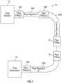
- a pipeline system may include pipe fittings, such as a midline pipe fitting and/or a pipe end fitting, and one or more pipe segments. More specifically, a pipe segment may generally be secured and sealed in one or more pipe fittings to facilitate fluidly coupling the pipe segment to another pipeline component, such as another pipe segment, another pipe fitting, a fluid source, and/or a fluid destination.
- a pipeline system 10 may generally, be coupled between a fluid source 12 and a fluid destination 14.
- the fluid source 12 may be a production well and the fluid destination 14 may be a fluid storage tank.
- the fluid source 12 may be a first (e.g., lease facility) storage tank and the fluid destination 14 may be a second (e.g., refinery) storage tank.
- the pipeline system 10 may generally convey fluid, such as gas and/or liquid, from the fluid source 12 to the fluid destination 14.
- the pipeline system 10 may be used in many applications, including without limitation, both onshore and offshore oil and gas applications.
- the pipeline system 10 may be used to transport hydrocarbon, aqueous fluid, and/or another suitable fluid, such as crude oil, petroleum, natural gas, produced water, fresh water, fracturing fluid, flowback fluid, carbon dioxide, or any combination thereof.
- a pipeline system 10 may include one or more pipe fittings 18 and one or more pipe segments 20.
- the depicted pipeline system 10 includes a first pipe segment 20A, a second pipe segment 20B, and an Nth pipe segment 20N.
- the depicted pipeline system 10 includes a first pipe (e.g., end) fitting 18A, which couples the fluid source 12 to the first pipe segment 20A, a second pipe (e.g., midline) fitting 18B, which couples the first pipe segment 20A to the second pipe segment 20B, and an Nth pipe (e.g., end) fitting 18N, which couples the Nth pipe segment 20N to the fluid destination 14.
- a pipeline system 10 may include fewer than three (e.g., two or one) pipe segments 20 or more than three (e.g., four, five, or more) pipe segments 20. Additionally or alternatively, in other embodiments, a pipeline system 10 may include fewer than four (e.g., three or two) pipe fittings 18 or more than four (e.g., five, six, or more) pipe fittings 18.
- a pipe segment 20 generally includes tubing that may be used to convey (e.g., transfer and/or transport) water, gas, oil, and/or any other suitable type of fluid.
- the tubing of a pipe segment 20 may be made of any suitable type of material, such as plastic, metal, and/or a composite (e.g., fiber-reinforced composite) material.
- the tubing of a pipe segment 20 may have multiple different tubing layers.
- the tubing of a pipe segment 20 may include a first high-density polyethylene (e.g., fluid containment) layer, one or more reinforcement (e.g., steel strip) layers external to the first high-density polyethylene layer, and a second high-density polyethylene (e.g., external corrosion protection) layer external to the one or more reinforcement layers.
- first high-density polyethylene e.g., fluid containment
- reinforcement e.g., steel strip
- second high-density polyethylene e.g., external corrosion protection
- one or more (e.g., second and/or Nth) pipe segments 20 in a pipeline system 10 may be curved (e.g., large deflection).
- the pipe segment 20 may be flexible, for example, such that the pipe segment 20 is spoolable on a reel and/or in a coil (e.g., during transport and/or before deployment of the pipe segment 20).
- one or more pipe segments 20 in the pipeline system 10 may be a flexible pipe, such as a bonded flexible pipe, an unbonded flexible pipe, a flexible composite pipe (FCP), a thermoplastic composite pipe (TCP), or a reinforced thermoplastic pipe (RTP).
- FCP flexible composite pipe
- TCP thermoplastic composite pipe
- RTP reinforced thermoplastic pipe
- a flexible pipe combines low bending stiffness with high axial tensile stiffness, which is achieved by a multi-layer construction.
- the two basic components are helical reinforcement layers and polymer sealing layers, which allow a much smaller radius of curvature than for a steel pipe with the same pressure capacity.
- an unbonded flexible has a lower bending stiffness than bonded flexible pipe due to the tubing layers not being bonded to one another. Bending stiffness may also be reduced in both bonded and unbonded flexible pipe when they have annular gaps between adjacent reinforcement strips in the reinforcement layers.
- increasing flexibility (e.g. reducing bending stiffness) of a pipe segment 20 may facilitate improving deployment efficiency of a pipeline system 10, for example, by having long coiled or reeled pipe segments transported to installation locations, thereby substantially reducing the number of pipe fittings relative to rigid pipe installations.
- the annular gaps between reinforcement strips are devoid of solid material.
- the free space in the tubing annulus of a pipe segment 20 may span the length of the pipe segment 20 and, thus, define one or more fluid conduits in the annulus of the tubing, which are separate from the pipe bore.
- a pipe segment 20 may enable fluid flow via its pipe bore, fluid flow via a fluid conduit defined within its tubing annulus, or both.
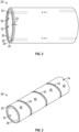
- FIG. 2 an example of a pipe segment 20, which includes tubing 22 with annular gaps (e.g., fluid conduits and/or free space) 24 defined in its annulus 25, is shown in FIG. 2 .
- the pipe segment tubing 22 includes multiple tubing layers including an internal pressure sheath (e.g., inner barrier) layer 26 and an outer sheath (e.g., outer barrier) layer 28.
- the internal pressure sheath layer 26 and/or the outer sheath layer 28 of the pipe segment tubing 22 may be made from composite material and/or plastic, such as high-density polyethylene (HDPE), raised temperature polyethylene (PE-RT), cross-linked polyethylene (XLPE), polyamide 11 (PA-11), polyamide 12 (PA-12), polyvinylidene difluoride (PVDF), or any combination thereof.
- high-density polyethylene HDPE
- PE-RT raised temperature polyethylene
- XLPE cross-linked polyethylene
- PA-11 polyamide 11
- PA-12 polyamide 12
- PVDF polyvinylidene difluoride
- an inner surface 30 of the internal pressure sheath layer 26 defines (e.g., encloses) a pipe bore 32 through which fluid can flow, for example, to facilitate transporting fluid from a fluid source 12 to a fluid destination 14.
- the internal pressure sheath layer 26 of a pipe segment 20 may be the innermost layer of the pipe segment 20.
- a carcass layer may be disposed under the internal pressure sheath layer 26 and, thus, the carcass layer may be the innermost layer of the pipe segment.
- the outer sheath layer 28 of a pipe segment 20 may be the outermost layer of the pipe segment 20.
- the outer sheath layer 28 may protect the pipe segment 20 against penetration of seawater and other external environmental conditions, corrosion, abrasion, and/or mechanical damage.
- the outer sheath layer 28 of a pipe segment 20 may include a number of sublayers.
- tubing annulus 25 of the pipe segment 20 is between its internal pressure sheath layer 26 and its outer sheath layer 28.
- the tubing annulus 25 of a pipe segment 20 may include one or more intermediate layers.
- annular gaps 24 running along the length of the pipe segment 20 are defined in the tubing annulus 25.
- a pipe segment 20 may include fewer than two (e.g., one) or more than two (e.g., three, four, or more) annular gaps 24 defined in its tubing annulus 25.
- an annular gap 24 defined in the tubing annulus 25 of a pipe segment 20 may run non-parallel to the pipe bore 32 of the pipe segment 20, for example, such that the annular gap 24 is skewed relative to the longitudinal axis of the pipe bore 32.
- FIG. 3 an example of a portion 36 of a pipe segment 20, which includes an internal pressure sheath layer 26 and an intermediate layer - namely a reinforcement (e.g., tensile and/or armor) layer 34 - included in the annulus 25 of its pipe segment tubing 22, is shown in FIG. 3 .
- the intermediate layers of pipe segment tubing 22 may include one or more tape layers, one or more insulation layers one or more intermediate sheath layers, one or more anti-wear layers, or any combination thereof.
- the reinforcement layer 34 includes a reinforcement strip 40.
- a reinforcement strip 40 in the pipe segment tubing 22 may be made at least in part using solid material that has a higher tensile strength and/or a higher linear modulus of elasticity than solid material that is used to make the internal pressure sheath layer 26 and/or the outer sheath layer 28 of the pipe segment tubing 22.
- the internal pressure sheath layer 26 may be made using plastic, such as high-density polyethylene (HDPE), while the reinforcement strip 40 may be made using metal, such as carbon steel, stainless steel, duplex stainless steel, super duplex stainless steel, or any combination thereof.
- HDPE high-density polyethylene
- a reinforcement strip 40 of the pipe segment tubing 22 may be made from electrically conductive material, which, at least in some instances, may enable communication of electrical (e.g., control and/or sensor) signals via the reinforcement strip 40.
- one or more reinforcement strips 40 of pipe segment tubing 22 may be made at least in part using a composite material.
- one or more other intermediate layers may be included in the annulus 25 of pipe segment tubing 22.
- a reinforcement strip 40 of the reinforcement layer 34 may be disposed on another intermediate layer, for example, instead of directly on the internal pressure sheath layer 26 of the pipe segment tubing 22.
- a reinforcement layer 34 of pipe segment tubing 22 may include multiple reinforcement strips 40.
- an outer sheath layer 28 may be disposed directly over the depicted reinforcement layer 34 and, thus, cover the depicted annular gap 24.
- the tubing annulus 25 of pipe segment tubing 22 may include multiple (e.g., two, three, four, or more) reinforcement layers 34.
- one or more other reinforcement layers 34 may be disposed over the depicted reinforcement layer 34.
- the reinforcement strips 40 in the one or more other reinforcement layers 34 may also each be helically disposed such that there are annular gaps (e.g., fluid conduits and/or free space) 24 between adjacent windings.
- a first other reinforcement strip 40 of a first other reinforcement layer 34 may be helically disposed on the depicted reinforcement strip 40 using the same non-zero lay angle as the depicted reinforcement strip 40 to cover (e.g., enclose) the depicted annular gap 24 and to define another annular gap 24 in the first other reinforcement layer 34.
- a second other reinforcement strip 40 of a second other reinforcement layer 34 may be helically disposed on the first other reinforcement strip 40 using another non-zero lay angle, which may be at or near the inverse of the non-zero lay angle of the depicted reinforcement strip 40, to define another annular gap 24 in the second other reinforcement layer 34.
- a third other reinforcement strip 40 of a third other reinforcement layer 34 may be helically disposed on the second other reinforcement strip 40 using the same non-zero lay angle as the second other reinforcement strip 40 to cover the other annular gap 24 in the second other reinforcement layer 34 and to define another annular gap 24 in the third other reinforcement layer 34.
- an outer sheath layer 28 may be disposed over the third other reinforcement layer 34 and, thus, cover (e.g., enclose) the other annular gap 24 in the third other reinforcement layer 34.
- a pipe segment 20 may be deployed in an elevated pressure environment, for example, underwater in a subsea application.
- a carcass layer may be disposed within (e.g., under) the internal pressure sheath layer 26 of the pipe segment 20.
- the internal pressure sheath layer 26 may be disposed around (e.g., over) the carcass layer and, thus, the carcass layer may be the innermost layer of the pipe segment tubing 22.
- the carcass layer 37 may be made from metal, such as carbon steel, stainless steel, duplex stainless steel, super duplex stainless steel, or any combination thereof. Additionally, as depicted, the carcass layer 37 is an interlocked layer in the pipe segment tubing 22.
- the pipe segment tubing 22 includes an internal pressure sheath layer 26 and an outer sheath layer 28. Furthermore, as depicted, the pipe segment tubing 22 includes intermediate layers 38 disposed between the internal pressure sheath layer 26 and the outer sheath layer 28 and, thus, in the annulus 25 of the pipe segment tubing 22. As depicted, the intermediate layers 38 include at least a reinforcement layer 34 with one or more reinforcement strips 40 that define one or more annular gaps (e.g., fluid conduits and/or free space) 24 in the tubing annulus 25.
- annular gaps e.g., fluid conduits and/or free space
- the intermediate layers 38 of pipe segment tubing 22 may include one or more tape layers, one or more intermediate sheath layers, one or more anti-wear layers, one or more insulation layers, or any combination thereof. Additionally, as described above, in some embodiments, pipe segment tubing 22 may include multiple reinforcement layers 34, which each include one or more reinforcement strips 40. In any case, in a pipeline system 10, the tubing 22 of a pipe segment 20 may be secured and sealed in a pipe fitting 18.
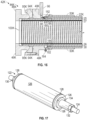
- a portion 42A of a pipeline system 10 which includes an example of a pipe fitting 18 - namely a swaged pipe fitting 44A - and pipe segment tubing 22A, is shown in FIG. 5 .
- a swaged pipe fitting 44 includes a fitting body 48, which defines a body (e.g., fitting) bore, a fitting connector (e.g., flange or weldneck) 46, and a fitting jacket 50.
- the fitting connector 46 is secured to the fitting body 48 to enable the swaged pipe fitting 44 to be connected to another pipeline component, such as a fluid source 12, a fluid destination 14, or another pipe fitting 18.
- a fitting jacket 50 of the swaged pipe fitting 44 is secured (e.g., welded) to its fitting body 48.
- the fitting jacket 50A of the swaged pipe fitting 44A may be compressed radially inward such that an inner surface 52 of the fitting jacket 50A engages (e.g., grips) an outer surface 54 of the pipe segment tubing 22A, for example, via a swage machine secured to the swaged pipe fitting 44A.
- the fitting jacket 50A is shown in its swaged state in FIG. 5 .
- a fitting jacket 50 Before being swaged, a fitting jacket 50 may be in an unswaged state in which its inner surface diameter is larger than the outer surface diameter of corresponding pipe segment tubing 22, thereby enabling the pipe segment tubing 22 to be inserted under (e.g., within) the fitting jacket 50.
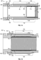
- FIG. 6 an example of a swage machine 56 and a portion 58B of a swaged pipe fitting 44 are shown in FIG. 6 .
- open space 60 is present between the inner surface 52 of the fitting jacket 50B and the outer surface 54 of the pipe segment tubing 22B, thereby enabling the pipe segment tubing 22B to be inserted (e.g., disposed) under (e.g., within) the fitting jacket 50B.
- the fitting jacket 50B is shown in its unswaged state in FIG. 6 .
- a swage machine 56 may include a grab plate 62 and a die plate 64.
- the grab plate 62 may include a grab attachment 66 with an L-shaped axial cross-section profile, which may interlock with an end of the fitting body 48 of a swaged pipe fitting 44.
- the grab plate 62 of a swage machine 56 may generally facilitate securing the swage machine 56 to a swaged pipe fitting 44.
- the die plate 64 of a swage machine 56 may have a set of die segments 68 loaded therein.
- the set of die segments 68 may be loaded into the die plate 64 such that the set of die segments 68 open toward the grab plate 62 of the swage machine 56.
- the die segments 68 When compressed against a fitting jacket 50 of a swaged pipe fitting 44 in an axial direction 70 toward the grab plate 62, the die segments 68 may compress the fitting jacket 50inward in a radial direction 72 around the circumference, for example, such that the inner surface 52 of the fitting jacket 50 engages the outer surface 54 of pipe segment tubing 22 disposed thereunder.
- a swaged pipe fitting 44 may include a support cylinder 74, which is disposed directly adjacent to an innermost (e.g., carcass) layer of the pipe segment tubing 22.
- the support cylinder 74B of the swaged pipe fitting 44 is disposed under (e.g., within) the carcass layer 37 of the pipe segment tubing 22B.
- the support cylinder 74 of a swaged pipe fitting 44 may extend beyond both ends of a corresponding fitting jacket 50.
- one or more intermediate (e.g., reinforcement) layers 38 of pipe segment tubing 22 may be compressed between the fitting jacket 50 and the support cylinder 74 of a swaged pipe fitting 44, thereby anchoring the one or more intermediate layers 38 in the swaged pipe fitting 44.
- the fitting jacket 50 of a swaged pipe fitting 44 may engage the outer sheath layer 28 of a pipe segment 20 and, thus, block the ingress of external environmental fluids, such as seawater into the tubing annulus 25 of the pipe segment 20, thereby sealing the outer sheath layer 28 of the pipe segment 20.
- the support cylinder 74 of a swaged pipe fitting 44 may include threading on its outer surface.
- the threading on the outer surface of the support cylinder 74 may threadingly interlock with the inner surface of the carcass layer 37 of a corresponding pipe segment 20.
- the support cylinder 74 may anchor the carcass layer 37 in the swaged pipe fitting 44.
- the support cylinder 74 of a swaged pipe fitting 44 may not include threading, for example, instead having a smooth, knurled, serrated or other outer surface condition.
- the support cylinder 74 of a swaged pipe fitting 44 may be integrated with its fitting connector 46 or its fitting body 48, for example, instead of being a separate component.
- a swaged pipe fitting 44 may not include a support cylinder 74, for example, when a support cylinder tool is used instead.
- a swage machine 56 may include one or more swaging actuators 76.
- the swage machine 56 includes a first swaging actuator 76A and an Nth swaging actuator 76N.
- one or more swaging actuators 76 in a swage machine 56 may be a fluid actuator, such as a hydraulic actuator or a pneumatic actuator.
- Each swaging actuator 76 of the swage machine 56 includes an actuator cylinder 78 and an actuator piston 80, which selectively extends out from the actuator cylinder 78 based at least in part on the supply of fluid (e.g., liquid and/or gas) to the actuator cylinder 78 and/or selectively retracts into the actuator cylinder 78 based at least in part on the extraction of fluid from the actuator cylinder 78.
- fluid e.g., liquid and/or gas
- each swaging actuator 76 is secured to the die plate 64 of the swage machine 56. Additionally, in the depicted example, the actuator piston 80 of each swaging actuator 76 extends through the die plate 64 and is secured to the grab plate 62 of the swage machine 56. As such, to perform a swaging operation, one or more swaging actuators 76 in the swage machine 56 may be operated to pull the grab plate 62 toward the die plate 64 via one or more reverse (e.g., retracting) strokes such that the fitting jacket 50B moves through the set of die segments 68 loaded in the die plate 64.
- reverse e.g., retracting
- a swage machine 56 may be operated to transition a fitting jacket 50 of a swaged pipe fitting 44 from its unswaged state to its swaged state and, thus, securing the swaged pipe fitting 44 to pipe segment tubing 22 inserted under the fitting jacket 50.
- a swage machine 56 may include fewer than two (e.g., one) swaging actuators 76 or more than two (e.g., three, four, or more) swaging actuators 76.
- a swage machine 56 may be operated to push its die plate 64 toward its grab plate 62 via one or more forward (e.g., extending) strokes such that a corresponding fitting jacket 50 moves through the set of die segments 68 loaded in the die plate 64.
- a swaged pipe fitting 44 may be swaged as a whole.
- a swaged pipe fitting 44 may include a grab sleeve, which may be disposed between the internal pressure sheath layer 26 and an intermediate layer 38 of pipe segment tubing 22 before a fitting jacket 50 of the swaged pipe fitting 44 is swaged around the pipe segment tubing 22.
- a grab sleeve 82 which may be included in a swaged pipe fitting 44, is shown in FIG. 7 .
- a grab sleeve 82 may be disposed between the internal pressure sheath layer 26 and an intermediate (e.g., reinforcement) layer 38 of pipe segment tubing 22.
- the grab sleeve 82 may be made from material that is more rigid than material used to make the internal pressure sheath layer 26 of the pipe segment tubing 22.
- the grab sleeve 82 may be made from metal, such as carbon steel, stainless steel, duplex stainless steel, super duplex stainless steel, or any combination thereof.
- the grab sleeve 82 includes a slit 84 along its longitudinal axis.
- the grab sleeve 82 may contract radially inward and engage the internal pressure sheath layer 26 of pipe segment tubing 22. Due to the resulting increased thickness, the grab sleeve 82 may facilitate anchoring an intermediate layer 38 (e.g., reinforcement layer 34) of the pipe segment tubing 22 between the grab sleeve 82 and a fitting jacket 50 of a corresponding swaged pipe fitting 44.
- an intermediate layer 38 e.g., reinforcement layer 34
- a grab sleeve 82 may include a crumple zone 86.
- the crumple zone 86 may include multiple openings 88 formed through the grab sleeve 82.
- a grab sleeve 82 may include a first tapered end 90A and a second tapered end 90B.
- a grab sleeve 82 may not include a tapered end 90 or include a single tapered end 90. Additionally, in other embodiments, a grab sleeve 82 may not include a dedicated crumple zone 86. Alternatively, in other embodiments, a swaged pipe fitting 44 may not include a grab sleeve 82.
- the fitting connector 46A may be secured to the fitting body 48A.
- the fitting connector 46 of a swaged pipe fitting 44 may be secured to a corresponding fitting body 48 via one or more threaded fasteners 92, such as a bolt or a screw.
- the fitting connector 46 of a swaged pipe fitting 44 may be secured to a corresponding fitting body 48 via fewer than two (e.g., one) threaded fasteners 92 or more than two (e.g., three, four, or more) threaded fasteners 92.
- the fitting connector 46 of a swaged pipe fitting 44 may be secured to a corresponding fitting body 48 via hot tooling, such as welding or brazing.
- a swaged pipe fitting 44 may include fitting seals.
- the fitting seals of a swaged pipe fitting 44 may include one or more face seals 94, which may be compressed between components of the swaged pipe fitting 44.
- a face seal 94A of the swaged pipe fitting 44A may be compressed between its fitting connector 46A and its fitting body 48A.
- the fitting seals of a swaged pipe fitting 44 include one or more internal pressure sheath seals 95, which are compressed against the internal pressure sheath layer 26 of a pipe segment 20, thereby sealing the internal pressure sheath layer 26 and, thus, block fluid flow between the pipe bore 32 and the tubing annulus 25 of the pipe segment 20.
- an internal pressure sheath seal 95A of the swaged pipe fitting 44A may be compressed against the internal pressure sheath layer 26 of the pipe segment tubing 22A due to compression between the fitting body 48A and the fitting connector 46A of the swaged pipe fitting 44A.
- the outer sheath layer 28 and each intermediate layer 38 of the pipe segment tubing 22 may be cut back relative to the internal pressure sheath layer 26, for example, while the internal pressure sheath layer 26 is cut back relative to the carcass layer 37 of the pipe segment tubing 22.
- one or more fitting seals in a swaged pipe fitting 44 may be made from metal.
- a fitting seal in the swaged pipe fitting 44 may made from carbon steel, stainless steel, duplex stainless steel, super duplex stainless steel, or any combination thereof.
- one or more fitting seals in a swaged pipe fitting 44 may be made from a non-metallic material.
- a fitting seal in the swaged pipe fitting 44 may made from a polymer, rubber, and/or plastic.
- one or more intermediate layers 38 in a pipe segment 20 may define one or more annular gaps (e.g., fluid conduits and/or free space) 24 in its tubing annulus 25.
- a swaged pipe fitting 44 may include one or more vent valves 96.
- a vent valve 96 of a swaged pipe fitting 44 may be fluidly connected to the annulus 25 of pipe segment tubing 22 via a fluid path 98 formed through the fitting body 48 of the swaged pipe fitting 44.
- a swaged pipe fitting 44 may not include a vent valve 96 or include more than one (e.g., two, three, or more) vent valve 96.
- an internal pressure sheath seal 95 of a swaged pipe fitting 44 may have a different geometry, such as a J-shaped axial cross-section profile, and/or disposed under a fitting jacket 50 of the swaged pipe fitting 44.
- a swaged pipe fitting 44 may include a carcass ring - namely a carcass isolating ring, which electrically isolates the carcass layer 37 of pipe segment tubing 22, or a carcass anchoring ring, which anchors the carcass layer 37 in the swaged pipe fitting 44.
- FIG. 8 a portion 42C of a pipeline system 10, which includes another example of a swaged pipe fitting 44C and pipe segment tubing 22C, is shown in FIG. 8 .
- the swaged pipe fitting 44C of FIG. 8 generally includes a fitting body 48C, a fitting connector 46C, a fitting jacket 50C, which is shown in its swaged state, a support cylinder 74C, and fitting seals - namely a face seal 94C and an internal pressure sheath seal 95C.
- the swaged pipe fitting 44C includes a carcass anchoring ring 100C, which is secured to the outer surface 101 of the carcass layer 37 of the pipe segment tubing 22C.
- the carcass anchoring ring 100 of a swaged pipe fitting 44 may be threaded and/or welded onto an outer surface of a corresponding carcass layer 37, which is an interlocked metal layer.
- the carcass anchoring ring 100 may be made from metal, such as carbon steel, stainless steel, duplex stainless steel, super duplex stainless steel, or any combination thereof.
- the internal pressure sheath layer 26 of the pipe segment tubing 22 may be cut back relative to the carcass layer 37.
- the fitting connector 46C of the swaged pipe fitting 44C accommodates the carcass anchoring ring 100C.
- the carcass anchoring ring 100C may be secured to the carcass layer 37 of the pipe segment tubing 22C before the fitting connector 46C is secured to the fitting body 48C.
- the carcass anchoring ring 100C which is secured to the carcass layer 37 of the pipe segment tubing 22C, may be trapped between the fitting connector 46C and the internal pressure sheath layer 26 of the pipe segment tubing 22C.
- the support cylinder 74C may have a smooth, knurled, or serrated outer surface, for example, instead of threading. In any case, in this manner, a swaged pipe fitting 44 may separately anchor the carcass layer 37 of corresponding pipe segment tubing 22 in the swaged pipe fitting 44.
- the swaged pipe fitting 44C may include one or more vent valves 96 and corresponding fluid paths 98 formed in its fitting body 48C. Additionally, in other embodiments, the swaged pipe fitting 44C may not include a support cylinder 74C, for example, when a support cylinder tool is used instead. Furthermore, in other embodiments, a swaged pipe fitting 44 may include a seal flange, which is secured between its fitting connector 46 and its fitting body 48, for example, to improve sealing integrity of the swaged pipe fitting 44. Moreover, in such embodiments, the swaged pipe fitting 44 may trap its carcass anchoring ring 100 between its fitting connector 46 and its seal flange, for example, to improve anchoring strength.
- FIG. 9 a portion 42D of a pipeline system 10, which includes a further example of a swaged pipe fitting 44D and pipe segment tubing 22D, is shown in FIG. 9 .
- the swaged pipe fitting 44D of FIG. 9 generally includes a fitting body 48D, a fitting connector 46D, a fitting jacket 50D, which is shown in its swaged state, a support cylinder 74D, an carcass anchoring ring 100D, and fitting seals - namely face seals 94D and an internal pressure sheath seal 95D.
- the swaged pipe fitting 44D includes a seal flange 102, which is secured between its fitting connector 46D and its fitting body 48D, for example, via one or more threaded fasteners 92, such as a bolt or a screw.
- the seal flange 102 of a swaged pipe fitting 44 may be secured to a corresponding fitting body 48D such that a face seal 94 is compressed therebetween and secured to a corresponding fitting connector 46 such that another face seal 94 is compressed therebetween.
- seal flange 102 of a swaged pipe fitting 44 may be secured to a corresponding fitting body 48 such that an internal pressure sheath seal 95 is compressed against the internal pressure sheath layer 26 of pipe segment tubing 22.
- the fitting connector 46D accommodates the carcass anchoring ring 100D.
- the carcass anchoring ring 100D is trapped between the fitting connector 46D and the seal flange 102., for example, instead of between the fitting connector 46D and the internal pressure sheath layer 26 of the pipe segment tubing 22D.
- the seal flange 102 is generally made from material, such as metal, that is more rigid than the internal pressure sheath layer 26 of pipe segment tubing 22, at least in some instances, implementing and/or deploying a swaged pipe fitting 44 in this manner may improve the strength with which the carcass layer 37 of the pipe segment tubing 22 is anchored in the swaged pipe fitting 44. Additionally, since the carcass layer 37 is anchored by the carcass anchoring ring 100D, in some embodiments, the support cylinder 74D may have a smooth, knurled or serrated outer surface, for example, instead of threading.
- the swaged pipe fitting 44D may include one or more vent valves 96 and corresponding fluid paths 98 formed in its fitting body 48D. Additionally, in other embodiments, the swaged pipe fitting 44D may not include a support cylinder 74C, for example, when a support cylinder tool is used instead. Furthermore, in other embodiments, the seal flange 102 may be secured to the fitting body 48D via a first one or more threaded fasteners 92 while the fitting connector 46D is secured to the seal flange 102 via a second one or more threaded fasteners 92.
- the carcass anchoring ring 100 of a swaged pipe fitting 44 may be disposed under a fitting jacket 50 of the swaged pipe fitting 44.
- an internal pressure sheath seal 95 of a swaged pipe fitting 44 may have a different geometry, such as a J-shaped axial cross-section profile.
- a portion 42E of a pipeline system 10 which includes another example of a swaged pipe fitting 44E and pipe segment tubing 22E, is shown in FIG. 10 .
- the swaged pipe fitting 44E of FIG. 10 generally includes a fitting body 48E, a fitting connector 46E, a fitting jacket 50E, which is shown in its unswaged state, a support cylinder 74E, a carcass anchoring ring 100E, and fitting seals - namely a face seal 94E and an internal pressure sheath seal 95E.
- the carcass anchoring ring 100E of the swaged pipe fitting 44E is disposed under its fitting jacket 50E. Nevertheless, as depicted, the carcass anchoring ring 100E is secured to the outer surface 101 of the carcass layer 37 of the pipe segment tubing 22E.
- the carcass anchoring ring 100E may be secured to the carcass layer 37 of the pipe segment tubing 22 at least in part by welding and/or threading the carcass anchoring ring 100E to the outer surface 101 of the carcass layer 37.
- the internal pressure sheath seal 95E of the swaged pipe fitting 44E is disposed under the fitting jacket 50E and has a J-shaped axial cross-section profile, for example, instead of a wedge-shaped axial cross-section profile.
- the internal pressure sheath seal 95E includes a hook portion 104 and a leg portion 106. The hook portion 104 of the internal pressure sheath seal 95E matingly interlocks with a retainer lip 108 on the carcass anchoring ring 100E to secure the internal pressure sheath seal 95E to the carcass anchoring ring 100E.
- the leg portion 106 of the internal pressure sheath seal 95E slants against the pipe segment tubing 22E.
- the outer sheath layer 28 of the pipe segment tubing 22 may be cut back relative to each intermediate layer 38 of the pipe segment tubing 22 while each intermediate layer 38 may be cut back relative to the internal pressure sheath layer 26 of the pipe segment tubing 22. Since disposed under the fitting jacket 50E, when the fitting jacket 50E is swaged, the internal pressure sheath seal 95E may be compressed radially inward against the internal pressure sheath layer 26 of the pipe segment tubing 22E, thereby sealing the internal pressure sheath layer 26.
- the swaged pipe fitting 44E may include one or more vent valves 96 and corresponding fluid paths 98 formed in its fitting body 48E. Additionally, in other embodiments, the swaged pipe fitting 44E may not include a support cylinder 74C, for example, when a support cylinder tool is used instead. Furthermore, in other embodiments, the fitting body 48 of a swaged pipe fitting 44 may be integrated with a corresponding fitting connector 46, such as a flange.
- an internal pressure sheath seal 95 of a swaged pipe fitting 44 may have a different geometry, such as a U-shaped axial cross-section profile, and/or be compressed between the fitting body 48 and the support cylinder 74 of the swaged pipe fitting 44.
- FIG. 11 a portion 42F of a pipeline system 10, which includes a further example of a swaged pipe fitting 44F and pipe segment tubing 22F, is shown in FIG. 11 .
- the swaged pipe fitting 44F of FIG. 11 generally includes a fitting body 48F, a fitting connector 46F, a fitting jacket 50F, which is shown in its swaged state, a support cylinder 74F, and fitting seals - namely face seals 94F and an internal pressure sheath seal 95F.
- the internal pressure sheath seal 95F of the swaged pipe fitting 44F has a U-shaped axial cross-section profile, for example, instead of a wedge-shaped axial cross-section profile or a J-shaped axial cross-section profile.
- the support cylinder 74F of the swaged pipe fitting 44F includes a flange 110, which extends radially outward, for example, instead of into the fitting connector 46F.
- the internal pressure sheath seal 95F is compressed against the internal pressure sheath layer 26 of the pipe segment tubing 22F due to compression between the flange 110 of the support cylinder 74D and the fitting body 48F of the swaged pipe fitting 44F, for example, instead of due to compression directly between the fitting body 48F and the fitting connector 46F of the swaged pipe fitting 44F.
- a support cylinder 74 of the swaged pipe fitting 44 may include threading 111 that extends outwardly along its outer surface 113.
- the threading 111 on the support cylinder 74 may threadingly engage an inner surface 115 of the carcass layer 37 of pipe segment tubing 22, thereby securing the support cylinder 74 to the carcass layer 37.
- the support cylinder 74 may be disposed under the carcass layer 37 of the pipe segment tubing 22 at least in part by rotating the support cylinder 74 relative to the carcass layer 37.
- internal pressure sheath seal 95F may be activated at least in part by securing the support cylinder 74F to the carcass layer 37 of the pipe segment tubing 22F.
- the support cylinder 74F of the swage pipe fitting 44F may have a smooth, serrated or knurled outer surface.
- the internal pressure sheath seal 95F may be activated at least in part by securing the fitting connector 46F to the fitting body 48F, for example, due to the flange 110 of the support cylinder 74F being disposed therebetween.
- a swaged pipe fitting 44 may include teeth (e.g., serrations) 109 that extend radially inward from the inner surface 52 of its fitting jacket 50. Additionally, as in the depicted example, in addition to a face seal 94 compressed between its fitting connector 46 and its fitting body 48, in some embodiments, a swaged pipe fitting 44 may include another face seal 94 disposed between the fitting body 48 and a fitting jacket 50.
- the swaged pipe fitting 44F may include one or more vent valves 96 and corresponding fluid paths 98 formed in its fitting body 48E. Additionally, in other embodiments, the internal pressure sheath seal 95F may have a wedge-shaped axial cross-section profile, for example, instead of a U-shaped axial cross-section profile. Furthermore, in other embodiments, the support cylinder 74 of a swaged pipe fitting 44 may be integrated with the fitting connector 46 of the swaged pipe fitting 44.
- FIG. 12 a portion 42G of a pipeline system 10, which includes another example of a swaged pipe fitting 44G and pipe segment tubing 22G, is shown in FIG. 12 .
- the swaged pipe fitting 44G of FIG. 12 generally includes a fitting body 48G, a fitting connector 46G, a fitting jacket 50G, which is shown in its swaged state, and fitting seals - namely a face seal 94G and an internal pressure sheath seal 95G.
- a support cylinder feature 74G of the swaged pipe fitting 44G is integrated with its fitting connector 46G.
- the fitting connector 46 of a swaged pipe fitting 44 may be inserted into the pipe segment tubing 22 before a fitting jacket 50 of the swaged pipe fitting 44 is swaged (e.g., conformally deformed) around the pipe segment tubing 22.
- the fitting connector 46 may be secured to the fitting body 48 of the swaged pipe fitting 44 after the fitting jacket 50 is swaged around the pipe segment tubing 22.
- the swaged pipe fitting 44G may include one or more vent valves 96 and corresponding fluid paths 98 formed in its fitting body 48G. Additionally, in other embodiments, the support cylinder 74 of a swaged pipe fitting 44 may be integrated with the fitting body 48 of the swaged pipe fitting 44.
- FIG. 13 a portion 42H of a pipeline system 10, which includes a further example of a swaged pipe fitting 44H and pipe segment tubing 22H, is shown in FIG. 13 .
- the swaged pipe fitting 44H of FIG. 13 generally includes a fitting body 48H, a fitting connector 46H, a fitting jacket 50H, which is shown in its swaged state, and fitting seals - namely a face seal 94H and an internal pressure sheath seal 95H.
- a support cylinder feature 74H of the swaged pipe fitting 44H is integrated with the fitting body 48H.
- the fitting body 48 of a swaged pipe fitting 44 may be inserted into the pipe segment tubing 22 before a fitting jacket 50 of the swaged pipe fitting 44 is swaged (e.g., conformally deformed) around the pipe segment tubing 22.
- the support cylinder feature 74H includes a carcass support section 112H, which supports the carcass layer 37 of the pipe segment tubing 22H, and an internal pressure sheath support section 114H, which supports the internal pressure sheath layer 26 of the pipe segment tubing 22H.
- the carcass layer 37 of the pipe segment tubing 22 may be cut back relative to the internal pressure sheath layer 26.
- the swaged pipe fitting 44H may nevertheless include a discrete internal pressure sheath seal 95H, which may be compressed between the internal pressure sheath support section 114H and the internal pressure sheath layer 26.
- the discrete internal pressure sheath seal 95H may be an O-ring seal or a belt (e.g., flat) seal.
- the discrete internal pressure sheath seal 95H may be obviated by the seal provided between the internal pressure sheath support section 114H and the internal pressure sheath layer 26 and, thus, not be included in the swaged pipe fitting 44H.
- the carcass support section 112H may include threading on its outer surface, for example, which threadingly engages an inner surface 115 of the carcass layer 37 of the pipe segment tubing 22H.
- the internal pressure sheath support section 114H may include teeth on its inner surface, for example, which engages the inner surface 30 of the internal pressure sheath layer 26.
- the carcass support section 112H may have a smooth outer surface
- the internal pressure sheath support section 114H may have a smooth outer surface, or both.
- the swaged pipe fitting 44H may include one or more vent valves 96 and corresponding fluid paths 98 formed in its fitting body 48H. Additionally, to account for thickness difference, in some embodiments, the fitting jacket 50H may have a stepped geometry such that the portion of the fitting jacket 50H that overlaps with the carcass support section 112H may be thinner while the portion of the fitting jacket 50H that overlaps with the internal pressure sheath support section 114H may be thicker. Furthermore, in other embodiments, the fitting body 48 of a swaged pipe fitting 44 may be integrated with a corresponding fitting connector 46, such as a weldneck. Alternatively, in other embodiments, a swaged pipe fitting 44 may not include a fitting connector 46. Moreover, in other embodiments, the internal pressure sheath support section 114 and the carcass support section 112 of a swaged pipe fitting 44 may be separate components.
- FIG. 14 a portion 42I of a pipeline system 10, which includes another example of a swaged pipe fitting 44I and pipe segment tubing 22I, is shown in FIG. 14 .
- the swaged pipe fitting 44I of FIG. 14 generally includes a fitting body 48I, a fitting connector 46I, a fitting jacket 50I, which is shown in its swaged state, and fitting seals - namely a face seal 94I and an internal pressure sheath seal 95I.
- the carcass support section 112I of the support cylinder feature 74I is implemented using a separate carcass support cylinder 116, for example, instead of being integrated with the internal pressure sheath support section 114I and the fitting body 48I of the swaged pipe fitting 44I.
- the carcass support cylinder 116 of the swaged pipe fitting 44 may be inserted into the pipe segment tubing 22 followed by the fitting body 48 of the swaged pipe fitting 44 before a fitting jacket 50 of the swaged pipe fitting 44 is swaged (e.g., conformally deformed) around the pipe segment tubing 22.
- a fitting jacket 50 of the swaged pipe fitting 44 is swaged (e.g., conformally deformed) around the pipe segment tubing 22.
- the swaged pipe fitting 44I may nevertheless include a discrete internal pressure sheath seal 95I, which may be compressed between the internal pressure sheath support section 114I and the internal pressure sheath layer 26.
- the discrete internal pressure sheath seal 95I may be an O-ring seal or a belt (e.g., flat) seal.
- the discrete internal pressure sheath seal 95I may be obviated by the seal provided between the internal pressure sheath support section 114I and the internal pressure sheath layer 26 and, thus, not be included in the swaged pipe fitting 44I.
- the carcass support cylinder 116 may include threading on its outer surface, for example, which threadingly engages an inner surface 115 of the carcass layer 37 of the pipe segment tubing 22I.
- the internal pressure sheath support section 114I may include teeth on its inner surface, for example, which engages the inner surface 30 of the internal pressure sheath layer 26.
- the carcass support section 112I may have a smooth outer surface
- the internal pressure sheath support section 114I may have a smooth outer surface, or both.
- the swaged pipe fitting 44I may include one or more vent valves 96 and corresponding fluid paths 98 formed in its fitting body 48I.
- the fitting jacket 50I may have a stepped geometry such that the portion of the fitting jacket 50I that overlaps with the carcass support section 112I may be thinner while the portion of the fitting jacket 50H that overlaps with the internal pressure sheath support section 114I is thicker.
- a swaged pipe fitting 44 may include a support cylinder 74, which is disposed around (e.g., over) the carcass layer 37 of pipe segment tubing 22.
- FIG. 15 a portion 42J of a pipeline system 10, which includes a further example of a swaged pipe fitting 44J and pipe segment tubing 22J, is shown in FIG. 15 .
- the swaged pipe fitting 44J of FIG. 15 generally includes a fitting body 48J, a fitting connector 46J, a fitting jacket 50J, which is shown in its swaged state, a support cylinder 74J, and face seals 94J.
- the support cylinder 74J of the swaged pipe fitting 44J is disposed around (e.g., over) the carcass layer 37 of the pipe segment tubing 22J, for example, instead of under the carcass layer 37.
- the support cylinder 74J may be inserted (e.g., disposed) between the carcass layer 37 and the internal pressure sheath layer 26 of the pipe segment tubing 22J.
- the support cylinder 74 of a swaged pipe fitting 44 may include a tapered end 118.
- inserting the support cylinder 74J under the internal pressure sheath layer 26 of the pipe segment tubing 22J may produce a flared section 119 in the internal pressure sheath layer 26 and a flared section 120 in each intermediate layer 38 of the pipe segment tubing 22J.
- a flared section 121 in the outer sheath layer 28 of the pipe segment tubing 22J also overlaps with the support cylinder 74J.
- the flared section 121 in the outer sheath layer 28 may also be produced by insertion of the support cylinder 74J under the internal pressure sheath layer 26.
- the flared section 121 in the outer sheath layer 28 of the pipe segment tubing 22J may be produced using a separate installation sleeve.
- the installation sleeve may be inserted (e.g., disposed) between the outer sheath layer 28 and an intermediate layer 38 of the pipe segment tubing 22J to produce the flared section 121 in the outer sheath layer 28.
- the flared section 121 of the outer sheath layer 28 may then be cut off from a remaining portion of the outer sheath layer 28 and the installation sleeve may be removed to enable the internal pressure sheath layer 26 and each intermediate layer 38 of the pipe segment tubing 22J to expand radially outward to produce flared sections therein when the support cylinder 74J is inserted under the internal pressure sheath layer 26.
- the flared section 121 of the outer sheath layer 28 may be reattached (e.g., poly welded) to the remaining portion of the outer sheath layer 28.
- the fitting jacket 50 of a swaged pipe fitting 44 may be implemented to extend beyond a flared section 121 in the outer sheath layer 28 of corresponding pipe segment tubing 22 and, thus, beyond the location the flared section 121 of the outer sheath layer 28 is reattached to the remaining portion of the outer sheath layer 28.
- the fitting jacket 50J may not extend beyond the flared section 121 in the outer sheath layer 28.
- the swaged pipe fitting 44J may include one or more vent valves 96 and corresponding fluid paths 98 formed in its fitting body 48J. Additionally, in other embodiments, the swaged pipe fitting 44J may anchor the carcass layer 37 of pipe segment tubing 22 therein via a carcass ring 100 similar to FIG. 8 or FIG. 9 . Furthermore, as mentioned above, in other embodiments, a swaged pipe fitting 44 may not include a support cylinder 74.
- a portion 42K of a pipeline system 10 which includes another example of a swaged pipe fitting 44K and pipe segment tubing 22K, is shown in FIG. 16 .
- the swaged pipe fitting 44K generally includes a fitting body 48K, a fitting connector 46K, a fitting jacket 50K, which is shown in its swaged state, a vent valve 96, and fitting seals - namely a face seal 94K and an internal pressure sheath seal 95K.
- the swaged pipe fitting 44K does not include a permanent support cylinder 74.
- a support cylinder tool may be used to support pipe segment tubing 22 during swaging.
- the support cylinder tool may be inserted into the pipe segment tubing 22 while in a contracted state and, subsequently, transitioned to an expanded state such that an outer surface of the support cylinder tool expands (e.g., is compressed) against and, thus, directly abuts an inner surface of the pipe segment tubing 22.
- the support cylinder tool may then be transitioned from its expanded state back to its contracted state and withdrawn from within the pipe segment tubing 22.
- the support cylinder tool may act as a temporary support cylinder 74.
- the support cylinder tool used with a swaged pipe fitting 44 may be an inflatable packer.
- the support cylinder tool used with a swaged pipe fitting 44 may be a special-purpose tool.
- the support cylinder tool 122 generally includes a threaded shaft 124, multiple support cylinder sections 126 disposed circumferentially around the threaded shaft 124, metallic elastic bands 128 disposed circumferentially around the support cylinder sections 126, an outer stationary nut 130 disposed around the threaded shaft 124, and an activation nut 132 disposed around the threaded shaft 124.
- the support cylinder tool 122 includes an activation collar 134, which is disposed between the support cylinder sections 126 and the activation nut 132, as well as a stationary collar, which is disposed between the outer stationary nut 130 and the support cylinder sections 126.
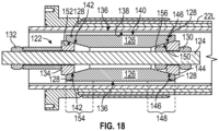
- FIG. 18 an example of a support cylinder tool 122 disposed within pipe segment tubing 22L is shown in FIG. 18 .
- open space 136 is present between an inner surface 138 of the pipe segment tubing 22L and an outer surface 140 of the support cylinder sections 126 of the support cylinder tool 122.
- the support cylinder tool 122 is shown in a contracted state, which enables the support cylinder tool 122 to be relatively freely inserted into and/or withdrawn from the pipe segment tubing 22L.
- the activation collar 134 of the support cylinder tool 122 has a wedge-shaped axial cross-section profile and, thus, a conical outer surface 142 while the stationary collar 144 also has a wedge-shaped axial cross-section profile and, thus, a conical outer surface 146.
- a first end 148 of the support cylinder sections 126 has a conical inner surface (e.g., female taper) 150, which can slide along the conical outer surface (e.g., male taper) 146 of the stationary collar 144, while the conical outer surface (e.g., male taper) 142 of the activation collar 134 can slide along a conical inner surface (e.g., female taper) 152 at a second (e.g., opposite) end 154 of the support cylinder sections 126.
- the stationary collar 144 is trapped between and, thus, held in place on the threaded shaft 124 of the support cylinder tool 122 via an outer stationary nut 130 and an inner stationary nut 156.
- the activation nut 132 may be rotated on the threaded shaft 124 to push more of the activation collar 134 under the support cylinder sections 126, thereby pushing the support cylinder sections 126 radially outward.
- the activation collar 134 may continue to be pushed under the support cylinder sections 126 until the outer surface 140 of the support cylinder sections 126 expands against the inner surface 138 of the pipe segment tubing 22L.
- the activation nut 132 may be rotated on the threaded shaft in an opposite direction to enable the pipe segment tubing 22L to push more of the activation collar 134 out from under the support cylinder sections 126 while contracting radially inward against the support cylinder sections 126.
- a support cylinder tool 122 used with a swaged pipe fitting 44 may include fewer than two (e.g., one) or more than two (e.g., three, four, or more) metallic elastic bands 128 disposed around its support cylinder sections 126.
- a support cylinder tool 122 used with a swaged pipe fitting 44 may include fewer than three (e.g., two) support cylinder sections 126 or more than three (e.g., four, five, or more) support cylinder sections 126.
- a support cylinder tool 122 may be implemented and/or operated to support pipe segment tubing 22 during a swaging operation used to secure a swaged pipe fitting 44 to the pipe segment tubing 22.
- a swaged pipe fitting 44 may include a carcass isolating ring 100, which electrically isolates the carcass layer 37 of corresponding pipe segment tubing 22 from the remainder of the swaged pipe fitting 44.
- the carcass isolating ring 100K of the swaged pipe fitting 44K may be made from an electrical insulative material, such as a polymer and/or plastic.
- a swaged pipe fitting 44 may include a spacer ring 182.
- the spacer ring 182 may directly abut the internal pressure sheath layer 26 of pipe segment tubing 22 and, thus, supports the internal pressure sheath layer 26, for example, to reduce the likelihood of a blow through in the internal pressure sheath layer 26 occurring within the swaged pipe fitting 44.
- the spacer ring 182 may bridge the structural support provided to the internal pressure sheath layer 26 by the one or more intermediate (e.g., reinforcement) layers 38 of the pipe segment tubing 22 and the structural support provided by the fitting body 48 of the swaged pipe fitting 44.
- the spacer ring 182 in a swaged pipe fitting 44 may directly abut an intermediate (e.g., reinforcement) layer 38 in the annulus 25 of pipe segment tubing 22, for example, to enable the swaged pipe fitting 44 to provide electrical continuity and, thus, cathodic protection to the intermediate layer 38.
- the spacer ring 182 may be made from the same type of metal as the intermediate layer 38 of the pipe segment tubing 22K.
- the spacer ring 182 and the intermediate layer 38 may both be made of carbon steel while the fitting body 48K is made of stainless steel.
- an electrical terminal 184 may be connected to the spacer ring 182 of the swaged pipe fitting 44 through its fitting body 48, for example, to enable an anode to be electrically connected to the intermediate layer 38 of corresponding pipe segment tubing 22.
- the spacer ring 182 of a swaged pipe fitting 44 may include an extension 186, which is disposed under the intermediate layer 38.
- the extension 186 on the spacer ring 182 may be inserted (e.g., disposed) between the intermediate layer 38 and the internal pressure sheath layer 26 of the pipe segment tubing 22.
- a fluid path 188 may be formed through the spacer ring 182 of a swaged pipe fitting 44 such that the fluid path 188 can be fluidly connected to another fluid path 98 that is formed in the fitting body 48 of the swaged pipe fitting 44 and fluidly connected to a vent valve 96.
- the swaged pipe fitting 44K may not include a vent valve 96 or include more than one (e.g., two, three, or more) vent valves 96. Additionally, in other embodiments, the swaged pipe fitting 44K may not include a spacer ring 182 or an electrical terminal 184. Alternatively, in other embodiments, the spacer ring 182 of the swaged pipe fitting 44K may not include an extension 186. Furthermore, in other embodiments, the swaged pipe fitting 44K may not include a carcass isolating ring 100K. In any case, in this manner, a swaged pipe fitting 44 may be implemented and/or deployed (e.g., installed) at pipe segment tubing 22.
- the process 190 includes cutting back a tubing layer of a pipe segment (process block 192), disposing a support cylinder directly adjacent to an innermost layer of the pipe segment (process block 194), and disposing a fitting jacket circumferentially around an outer sheath layer of the pipe segment (process block 196). Additionally, the process 190 generally includes conformally deforming the fitting jacket around the pipe segment (process block 198) and securing a fitting connector to a fitting body that is secured to the fitting jacket (process block 202).
- a process 190 for installing a swaged pipe fitting 44 at a pipe segment 20 may include one or more additional blocks and/or omit one or more of the depicted blocks.
- some embodiments of the process 190 may include reattaching a cut back portion of an outer sheath layer of the pipe segment to a remaining portion of the outer sheath layer (process block 204) while other embodiments of the process 190 do not.
- some embodiments of the process 190 may include disposing a grab sleeve between an internal pressure sheath layer and an intermediate layer of the pipe segment (process block 206) while other embodiments of the process 190 do not.
- some embodiments of the process 190 may include disposing a spacer ring directly adjacent to the intermediate layer of the pipe segment (process block 208) while other embodiments of the process do not.
- some embodiments of the process 190 may include disposing an internal pressure sheath seal around the internal pressure sheath layer of the pipe segment (process block 209) while other embodiments of the process 190 do not.
- some embodiments of the process 190 may include securing a seal flange to the fitting body (process block 210) while other embodiments of the process 190 do not.
- some embodiments of the process 190 may include securing a carcass ring to a carcass layer of the pipe segment (process block 212) while other embodiments of the process 190 do not.
- some embodiments of the process 190 may include removing a support cylinder tool from the pipe segment (process block 214) while other embodiments of the process 190 do not.
- one or more of the depicted blocks may be performed in a different order, for example, such that the fitting jacket is disposed around the outer sheath layer of the pipe segment before the support cylinder is disposed directly adjacent to the innermost layer of the pipe segment.
- one or more tubing layers of a pipe segment 20 at which a swaged pipe fitting 44 is to be deployed may be cut back.
- deploying a swaged pipe fitting 44 at a pipe segment 20 may generally include cutting back one or more tubing layers of the pipe segment 20 (process block 192).
- the outer sheath layer 28 and each intermediate layer 38 of the pipe segment 20 may be cut back relative to the internal pressure sheath layer 26 of the pipe segment 20, for example, to enable an internal pressure sheath seal 95 of the swaged pipe fitting 44 to be compressed against the outer surface 97 of the internal pressure sheath layer 26 (process block 216).
- a swaged pipe fitting 44 may include a carcass ring 100, which is secured to the carcass layer 37 of a pipe segment 20 to anchor the carcass layer 37 in the swaged pipe fitting 44.
- the carcass ring 100 may be secured (e.g., welded and/or threaded) to the outer surface 101 of the carcass layer 37.
- the internal pressure sheath layer 26 of the pipe segment 20 may be cut back relative to the carcass layer 37 (process block 218).
- the outer sheath layer 28 of the pipe segment 20 may be cut back relative to an intermediate layer 38 of the pipe segment 20 (process block 220).
- the outer sheath layer 28 may be cut back relative to the intermediate layer 38 to enable the leg portion 106 of an internal pressure sheath seal 95, which has a J-shaped axial cross-section profile, to slant against the tubing 22 of the pipe segment 20.
- FIG. 10 the outer sheath layer 28 may be cut back relative to the intermediate layer 38 to enable the leg portion 106 of an internal pressure sheath seal 95, which has a J-shaped axial cross-section profile, to slant against the tubing 22 of the pipe segment 20.
- the cutoff portion of the outer sheath layer 28 may be a flared section 121, for example, which may be produced by inserting a temporary installation sleeve under the outer sheath layer 28.
- the carcass layer 37 of the pipe segment 20 may be cut back relative to the internal pressure sheath layer 26 of the pipe segment 20, for example, to enable an internal pressure sheath seal 95 of a swaged pipe fitting 44 to be compressed against the inner surface 30 of the internal pressure sheath layer 26 and/or the swaged pipe fitting 44 to support the internal pressure sheath layer 26 during a swaging operation (process block 222).
- a support cylinder 74 may be disposed directly adjacent to the innermost (e.g., carcass or internal pressure sheath) layer of the pipe segment 20.
- deploying a swaged pipe fitting 44 at a pipe segment 20 may generally include disposing a support cylinder 74 directly adjacent to (e.g., under or over) the innermost layer of the pipe segment 20 (process block 194).
- the support cylinder 74 may be a component (e.g., feature) of the swaged pipe fitting 44.
- the support cylinder 74 of a swaged pipe fitting 44 may be disposed under (e.g., within) the carcass layer 37 of a corresponding pipe segment 20 (process block 224).
- a support cylinder feature of a swaged pipe fitting 44 may be integrated with its fitting connector 46 and, thus, disposing the support cylinder 74 under the carcass layer 37 may include inserting the fitting connector 46 under the carcass layer 37 of the pipe segment 20.
- a support cylinder feature of a swaged pipe fitting 44 may be integrated with its fitting body 48 and, thus, disposing the support cylinder 74 under the carcass layer 37 may include inserting the fitting body 48 under the carcass layer 37 of the pipe segment 20.
- the support cylinder 74 of a swaged pipe fitting 44 may be inserted between the carcass layer 37 and the internal pressure sheath layer 26 of a corresponding pipe segment 20 (process block 226).
- the support cylinder 74 of the swaged pipe fitting 44 may be disposed under (e.g., within) the internal pressure sheath layer 26 and each intermediate layer 38 of the pipe segment 20 to produce a flared section 119 along the internal pressure sheath layer 26 and flared sections 120 along each intermediate layer 38.
- the cut back portion (e.g., flared section 121) of the outer sheath layer 28 may then be reattached (e.g., poly welded) back to the remaining portion of the outer sheath layer 28 to cover the flared section 120 in each intermediate layer 38 and the flared section 119 in the internal pressure sheath layer 26 (process block 204).
- a swaged pipe fitting 44 may not include a support cylinder 74.
- a support cylinder tool 122 may be used to temporarily support the tubing 22 of a pipe segment 20 while the swaged pipe fitting 44 is being swaged thereto.
- the support cylinder tool 122 may be inserted into the pipe bore 32 of the pipe segment 20 while in its contracted state and, subsequently, transitioned from its contracted state to its expanded state such that the outer surface 140 of its support cylinder sections 126 of the support cylinder tool 122 expands against the inner surface of an innermost layer of the pipe segment 20 (process block 228).
- the support cylinder tool 122 may be operated to transition from its contracted state to its expanded state at least in part by rotating an activation nut 132 to push more of a corresponding activation collar 134 under the support cylinder sections 126 of the support cylinder tool 122.
- a fitting jacket 50 of the swaged pipe fitting 44 may be disposed circumferentially around the outer sheath layer 28 of the pipe segment 20 (process block 196).
- a fitting jacket 50 of a swaged pipe fitting 44 may be secured (e.g., welded) to the fitting body 48 of the swaged pipe fitting 44.
- disposing the fitting jacket 50 of a swaged pipe fitting 44 circumferentially around the outer sheath layer 28 of a pipe segment 20 may include disposing the fitting body 48 of the swaged pipe fitting 44 adjacent to the pipe segment 20 (process block 236).
- the fitting body 48 of a swaged pipe fitting 44 may be made from a different type of metal as compared to an intermediate layer 38 of a corresponding pipe segment 20.
- the fitting body 48 may be made of stainless steel while solid material in the intermediate layer 38 is made of carbon steel.
- a swaged pipe fitting 44 may include a spacer ring 182, which is made from the same type of metal as the intermediate layer 38 of the pipe segment 20 and can be disposed directly adjacent to the intermediate layer 38 of the pipe segment 20.
- deploying the swaged pipe fitting 44 at a pipe segment 20 may include disposing a spacer ring 182 directly adjacent to an intermediate layer 38 of the pipe segment 20, for example, at least in part by inserting an extension 186 on the spacer ring 182 under the intermediate layer 38 (process block 208).
- the spacer ring 182 may be disposed directly adjacent to the internal pressure sheath layer 26, for example, at least in part by inserting an extension 186 on the spacer ring 182 between the internal pressure sheath layer 26 and the one or more reinforcement layers 34 (process block 208).
- the fitting jacket 50 of the swaged pipe fitting 44 may then be conformally deformed (e.g., swaged) around the tubing 22 of the pipe segment 20 such that the inner surface 52 of the fitting jacket 50 engages the outer surface 54 of the pipe segment tubing 22 and, thus, facilitates securing the swaged pipe fitting 44 to the pipe segment 20 as well as sealing the pipe segment tubing 22 within the swaged pipe fitting 44 (process block 198).
- a fitting jacket 50 of a swaged pipe fitting 44 may be swaged using a swage machine 56.
- a swage machine 56 may generally include a grab plate 62, which may facilitate securing the swage machine 56 to the fitting body 48 of a swaged pipe fitting 44, for example, via a grab attachment 66 that has an L-shaped axial cross-section profile.
- a swage machine 56 may generally include a die plate 64, which may enable a set of die segments 68 to be loaded in the swage machine 56 such that the set of die segments 68 compress a fitting jacket 50 of a swaged pipe fitting 44 inwardly in a radial direction 72 when moved over the fitting jacket 50 in an axial direction 70.
- conformally deforming the fitting jacket 50 of a swaged pipe fitting 44 around a pipe segment 20 may include securing a grab plate 62 of a swage machine 56 to the fitting body 48 of the swaged pipe fitting 44 (process block 238) and moving a die plate 64 of the swage machine 56 over the fitting jacket 50 (process block 240).
- a swaged pipe fitting 44 may include a grab sleeve 82, which may be disposed between the internal pressure sheath layer 26 and the intermediate layer 38 of the pipe segment 20.
- deploying the swaged pipe fitting 44 at a pipe segment 20 may include disposing a grab sleeve 82 between the internal pressure sheath layer 26 and an intermediate layer 38 of the pipe segment 20 before a fitting jacket 50 of the swaged pipe fitting 44 is disposed around the outer sheath layer 28 of the pipe segment 20 (process block 206).
- the grab sleeve 82 may include a slit 84 that enables the grab sleeve 82 to grab onto the internal pressure sheath layer 26 when the fitting jacket 50 is swaged such that the intermediate layer 38 of the pipe segment 20 is compressed between the grab sleeve 82 and the fitting jacket 50 and, thus, anchored in the swaged pipe fitting 44. Additionally or alternatively, swaging a fitting jacket 50 of a swaged pipe fitting 44 may compress one or more intermediate (e.g., reinforcement) layers 38 of a corresponding pipe segment 20 between the fitting jacket 50 and a support cylinder 74 of the swaged pipe fitting 44, thereby anchoring the one or more intermediate layers 38 in the swaged pipe fitting 44.
- intermediate e.g., reinforcement
- a support cylinder tool 122 may be temporarily used to support the tubing 22 of a pipe segment 20 during a swaging operation.
- the support cylinder tool 122 may be removed from within the pipe segment 20 (process block 214).
- the support cylinder tool 122 may be operated to transition from its expanded state to its contracted state and withdrawn from within the pipe segment 20 while in its contracted state (process block 250).
- the support cylinder tool 122 may be operated to transition from its expanded state to its contracted state at least in part by rotating an activation nut 132 to enable the pipe segment 20 to push more of a corresponding activation collar 134 out from under the support cylinder sections 126 while contracting radially inward against the support cylinder sections 126.
- an internal pressure sheath seal 95 of a swaged pipe fitting 44 may be disposed under a fitting jacket 50 of the swaged pipe fitting 44.
- the internal pressure sheath seal 95 may have a J-shaped axial cross-section profile that includes a hook portion 104, which interlocks with a carcass ring 100 of the swaged pipe fitting 44, and a leg portion 106, which may slant against the tubing 22 of a pipe segment 20.
- the internal pressure sheath seal 95 may be compressed against the pipe segment tubing 22, thereby activating the internal pressure sheath seal 95 (process block 242).
- an internal pressure sheath seal 95 of a swaged pipe fitting 44 may be compressed against the fitting body 48 of the swaged pipe fitting 44.
- installing the swaged pipe fitting 44 to a pipe segment 20 may include disposing an internal pressure sheath seal 95 around the internal pressure sheath layer 26 of the pipe segment 20 after (e.g., behind) the fitting body 48 of the swaged pipe fitting 44 (process block 209).
- the internal pressure sheath seal 95 may be compressed between the fitting body 48 and a seal flange 102 of the swaged pipe fitting 44.
- installing the swaged pipe fitting 44 to a pipe segment 20 may include securing a seal flange 102 to the fitting body 48 of the swaged pipe fitting 44 (process block 210), for example, such that a corresponding internal pressure sheath seal 95 is compressed against the internal pressure sheath layer 26 of the pipe segment 20 due to compression between the fitting body 48 and the seal flange 102 and, thus, activated (process block 244).
- a seal flange 102 may be secured to a corresponding fitting body 48 via one or more threaded fasteners 92, such as a bolt or a screw.
- a seal flange 102 may be secured to a corresponding fitting body 48 via hot tooling, such as welding and/or brazing.
- the fitting connector 46 of the swaged pipe fitting 44 may then be secured to its fitting body 48 (process block 202).
- the fitting connector 46 may be secured to a seal flange 102 of the swaged pipe fitting 44, which is secured to the fitting body 48.
- a fitting connector 46 may be secured to a corresponding seal flange 102 and a corresponding fitting body 48 via one or more threaded fasteners 92, such as a bolt or a screw.
- a fitting connector 46 may be secured to a corresponding seal flange 102 via hot tooling, such as welding and/or brazing.
- the fitting connector 46 of a swaged pipe fitting 44 is secured directly to a corresponding fitting body 48, for example, via one or more threaded fasteners 92, such as a bolt or a screw, and/or hot tooling, such as welding and/or brazing.
- an internal pressure sheath seal 95 of a swaged pipe fitting 44 is compressed between its fitting body 48 and its fitting connector 46.
- securing the fitting connector 46 to the fitting body 48 compresses the internal pressure sheath seal 95 therebetween such that the internal pressure sheath seal 95 is compressed against the internal pressure sheath layer 26 of a pipe segment 20 and, thus, activated (process block 246).
- a swaged pipe fitting 44 may include a carcass anchoring ring 100, which may be secured to the carcass layer 37, and the fitting connector 46 of the swaged pipe fitting 44 may accommodate the carcass ring 100.
- installing the swaged pipe fitting 44 to a pipe segment 20 may include securing a carcass ring 100 to the carcass layer 37 of the pipe segment 20, for example, at least in part by welding and/or threading the carcass ring 100 onto the outer surface 101 of the carcass layer 37 (process block 212).
- securing the fitting connector 46 to the fitting body 48 may include disposing the fitting connector 46 over a carcass ring 100, which is secured to the carcass layer 37 of a pipe segment 20, for example, such that the carcass ring 100 is trapped between the fitting connector 46 and the internal pressure sheath layer 26 of the pipe segment 20 or between the fitting connector 46 and a seal flange 102 of the swaged pipe fitting 44 (process block 248).
- the present disclosure provides techniques for implementing and/or deploying a swaged pipe fitting.
Landscapes
- Engineering & Computer Science (AREA)
- General Engineering & Computer Science (AREA)
- Mechanical Engineering (AREA)
- Rigid Pipes And Flexible Pipes (AREA)
- Protection Of Pipes Against Damage, Friction, And Corrosion (AREA)
- Pressure Vessels And Lids Thereof (AREA)
- Earth Drilling (AREA)
Claims (11)
- System, aufweisend:eine Rohrsegmentleitung (22), wobei die Rohrsegmentleitung (22) aufweist:eine Karkassenschicht (37);eine um die Karkassenschicht (37) herum angeordnete Innendruckmantelschicht (26);eine um die Innendruckmantelschicht (26) herum angeordnete Verstärkungsschicht (34); undeine um die Verstärkungsschicht (34) herum angeordnete äußere Mantelschicht (28); undein an der Rohrsegmentleitung (22) befestigtes Quetschfitting (44), wobei das Quetschfitting (44) aufweist:einen Fittingkörper (48), der eine Bohrung definiert;einen Fittingverbinder (46), der am Fittingkörper (48) befestigt ist, um zu ermöglichen, dass das Quetschfitting (44) mit einer anderen Rohrleitungskomponente (12, 14, 18) verbunden werden kann;eine Innendruckmanteldichtung (95), die dafür konfiguriert ist, die Innendruckmantelschicht (26) der Rohrsegmentleitung (22) innerhalb des Quetschfittings (44) abzudichten; undeine am Fittingkörper (48) befestigte Fittingummantelung (50), wobei die Fittingummantelung (50) um die Rohrsegmentleitung (22) herum formschlüssig verformt wird, um die Verstärkungsschicht (34) der Rohrsegmentleitung (22) im Quetschfitting (44) zu verankern,dadurch gekennzeichnet, dassdie Innendruckmanteldichtung (95) des Quetschfittings (44) gegen die Innendruckmantelschicht (26) der Rohrsegmentleitung (22) aufgrund einer Kompression zwischen dem Fittingverbinder (46) und dem Fittingkörper (48) des Quetschfittings (44) zusammengedrückt wird.
- System nach Anspruch 1, wobei die Karkassenschicht (37) der Rohrsegmentleitung (22) eine damit in Eingriff stehende Metallschicht aufweist.
- System nach Anspruch 1, wobei die Fittingummantelung (50) des Quetschfittings (44) um die Rohrsegmentleitung (22) herum formschlüssig verformt wird, um die äußere Mantelschicht (28) der Rohrsegmentleitung (22) innerhalb des Quetschfittings (44) abzudichten.
- System nach Anspruch 1, aufweisend eine Pressmaschine (56), wobei die Pressmaschine (56) aufweist:eine Greiferplatte (62), die dafür konfiguriert ist, die Pressmaschine (56) am Fittingkörper (48) des Quetschfitttings (44) zu sichern; undeine Stempelplatte (64), die einen Satz von Stempelsegmenten (68) aufweist, wobei die Pressmaschine (56) dafür konfiguriert ist, die Greiferplatte (62) und die Stempelplatte (64) aufeinander zu zu bewegen, so dass der Satz von Stempelsegmenten (68) die Fittingummantelung (50) des Quetschfittings (44) radial nach innen zusammenpresst.
- System nach Anspruch 1, wobei:die Verstärkungsschicht (34) einen Fluidkanal (24) innerhalb eines Rohrleitungsrings (25) der Rohrsegmentleitung (22) definiert; unddas Quetschfitting (44) aufweist:einen Fluidpfad (98), der im Fittingkörper (48) des Quetschfittings (44) derart definiert ist, dass der Fluidpfad (98) mit dem Fluidkanal (24) im Rohrleitungsring (25) der Rohrsegmentleitung (22) fluidtechnisch verbunden ist; undein Entlüftungsventil (96), das mit dem im Fittingkörper (48) definierten Fluidpfad (98) fluidtechnisch verbunden ist.
- System nach Anspruch 1, wobei das Quetschfitting (44) aufweist:einen Karkassenverankerungsring (100), der an einer Außenfläche (101) der Karkassenschicht (37) der Rohrsegmentleitung (22) befestigt ist,wobei der Fittingverbinder (46) über dem Karkassenverankerungsring (100) angeordnet ist, um die Karkassenschicht (37) der Rohrsegmentleitung (22) im Quetschfitting (44) zu verankern; und/odereine Greifhülse (82), die zwischen der Innendruckmantelschicht (26) und der Verstärkungsschicht (34) der Rohrsegmentleitung (22) eingesetzt wird, bevor die Fittingummantelung (50) formschlüssig um die Rohrsegmentleitung (22) herum verformt wird.
- System nach Anspruch 1, wobei das Quetschfitting (44) einen Stützzylinder (74) aufweist, der unter der Karkassenschicht (37) der Rohrsegmentleitung (22) angeordnet ist, wobei vorzugsweise ein Gewinde (111) auf einer Außenfläche (113) des Stützzylinders (74) mit einer Innenfläche (115) der Karkassenschicht (37) der Rohrsegmentleitung (22) in Gewindeeingriff gebracht wird, um die Karkassenschicht (37) im Quetschfitting (44) zu verankern.
- System nach Anspruch 7, wobei:der Stützzylinder (74) des Quetschfittings (44) einen sich radial nach außen erstreckenden Flansch (100) aufweist, unddie Innendruckmanteldichtung (95) ein U-förmiges axiales Querschnittsprofil aufweist und aufgrund der Kompression zwischen dem Flansch (100) auf dem Stützzylinder (74) und dem Fittingkörper (48) des Quetschfittings (44) gegen die Innendruckmantelschicht (26) der Rohrsegmentleitung (22) zusammengedrückt wird (48), und/oderder Stützzylinder (74) mit dem Fittingkörper (48) oder dem Fittingverbinder (46) des Quetschfittings (44) integriert ist.
- System nach Anspruch 1, wobei:das Quetschfitting (44) einen zwischen der Karkassenschicht (37) und der Innendruckmantelschicht (26) der Rohrsegmentleitung (22) angeordneten Stützzylinder (74) aufweist,die Innendruckmantelschicht (26) einen ersten konisch erweiterten Abschnitt (119) aufweist, der den Stützzylinder (74) überlappt,die Verstärkungsschicht (34) einen zweiten konisch erweiterten Abschnitt (120) aufweist, der den Stützzylinder (74) überlappt, unddie äußere Mantelschicht (28) einen dritten konisch erweiterten Abschnitt (121) aufweist, der den Stützzylinder (74) überlappt.
- Verfahren zum Installieren eines Quetschfittings (44) auf einem Rohrsegment (20), mit den Schritten:Anordnen einer Fittingummantelung (50) des Quetschfittings (44) in der Umfangsrichtung um eine Rohrsegmentleitung (22) des Rohrsegments (20), wobei die Fittingummantelung (50) an einem Fittingkörper (48) des Quetschfittings (44) befestigt wird, der eine Körperbohrung definiert;Anordnen eines Stützzylinders (74, 122) direkt benachbart zu einer Karkassenschicht (37) des Rohrsegments (20), wobei die Karkassenschicht (37) des Rohrsegments (20) eine damit in Eingriff stehende Metallschicht aufweist;konformes Verformen der Fittingummantelung (50) des Quetschfittings (44) um die Rohrsegmentleitung (22) des Rohrsegments (20) herum, um das Quetschfitting (44) am Rohrsegment (20) zu befestigen und die Rohrsegmentleitung (22) des Rohrsegments (20) innerhalb des Quetschfittings (44) abzudichten; undBefestigen eines Fittingverbinders (46) am Fittingkörper (48), um zu ermöglichen, dass das Quetschfitting (44) mit einer anderen Rohrleitungskomponente (12, 14, 18) verbunden werden kann,dadurch gekennzeichnet, dassdas Befestigen des Fittingverbinders (46) am Fittingkörper (48) das Zusammendrücken einer Fittingdichtung (95) gegen eine Innendruckmantelschicht (26) des Rohrsegments (20) durch Zusammendrücken der Fittingdichtung (95) zwischen dem Fittingverbinder (46) und dem Fittingkörper (48) aufweist.
- Verfahren nach Anspruch 10, wobeidas konforme Verformen der Fittingummantelung (50) des Quetschfittings (44) das Zusammendrücken einer Verstärkungsschicht (34) des Rohrsegments (20) zwischen der Fittingummantelung (50) und dem Stützzylinder (74, 122) aufweist, um die Verstärkungsschicht (34) im Quetschfitting (44) zu verankern; und/oderdas Anordnen des Stützzylinders (74, 122) direkt benachbart zur Karkassenschicht (37) des Rohrsegments (20) aufweist:Einsetzen eines Stützzylinderwerkzeugs (122) in das Rohrsegment (20), während sich eine Vielzahl von Stützzylinderabschnitten (126) des Stützzylinderwerkzeugs (122) in einem zusammengezogenen Zustand befinden;Überführen des Stützzylinderwerkzeugs (122) vom zusammengezogenen Zustand in einen expandierten Zustand, in dem sich die Vielzahl von Stützzylinderabschnitten (126) des Stützzylinderwerkzeugs (122) gegen die Karkassenschicht (37) des Rohrsegments (20) ausdehnen;Überführen des Stützzylinderwerkzeugs (122) vom expandierten Zustand zurück in den zusammengezogenen Zustand, nachdem die Fittingummantelung (50) um die Rohrsegmentleitung (22) des Rohrsegments (20) herum konform verformt wurde; undZurückziehen des Stützzylinderwerkzeugs (122) vom Rohrsegment (20), während sich das Stützzylinderwerkzeug (122) im zusammengezogenen Zustand befindet.
Applications Claiming Priority (2)
| Application Number | Priority Date | Filing Date | Title |
|---|---|---|---|
| US201962939375P | 2019-11-22 | 2019-11-22 | |
| PCT/US2020/061574 WO2021102306A1 (en) | 2019-11-22 | 2020-11-20 | Swaged pipe fitting systems and methods |
Publications (3)
| Publication Number | Publication Date |
|---|---|
| EP4058709A1 EP4058709A1 (de) | 2022-09-21 |
| EP4058709A4 EP4058709A4 (de) | 2024-03-27 |
| EP4058709B1 true EP4058709B1 (de) | 2025-05-07 |
Family
ID=75973821
Family Applications (1)
| Application Number | Title | Priority Date | Filing Date |
|---|---|---|---|
| EP20891193.3A Active EP4058709B1 (de) | 2019-11-22 | 2020-11-20 | Stauchrohrverbindungssysteme und verfahren |
Country Status (11)
| Country | Link |
|---|---|
| US (2) | US11378207B2 (de) |
| EP (1) | EP4058709B1 (de) |
| CN (1) | CN114945768A (de) |
| AR (1) | AR120545A1 (de) |
| BR (1) | BR112022010009A2 (de) |
| CA (1) | CA3162606A1 (de) |
| CO (1) | CO2022008510A2 (de) |
| DK (1) | DK4058709T3 (de) |
| MX (1) | MX2022006233A (de) |
| SA (1) | SA522432680B1 (de) |
| WO (1) | WO2021102306A1 (de) |
Families Citing this family (7)
| Publication number | Priority date | Publication date | Assignee | Title |
|---|---|---|---|---|
| BR112022010009A2 (pt) * | 2019-11-22 | 2022-09-06 | Trinity Bay Equipment Holdings Llc | Sistemas e métodos de encaixe de tubo estampado |
| EP4150240B1 (de) * | 2020-05-14 | 2025-01-29 | Swagelok Company | Schlauchanordnung und verfahren zu ihrer herstellung und verwendung |
| BR102021017363A2 (pt) * | 2021-09-01 | 2023-03-14 | Petróleo Brasileiro S.A. - Petrobras | Sistema de ancoragem por auto travamento de mangas de fibras tramadas |
| US12169037B2 (en) | 2021-12-20 | 2024-12-17 | Parker-Hannifin Corporation | Fitting assembly for collapse-resistant hose |
| US20230304604A1 (en) * | 2022-03-25 | 2023-09-28 | Trinity Bay Equipment Holdings, LLC | Inflatable pipe drum systems and methods |
| WO2024233842A2 (en) * | 2023-05-10 | 2024-11-14 | Crane Chempharma & Energy Corp. | Field repairable flangeless lined piping connection |
| GB202311601D0 (en) * | 2023-07-27 | 2023-09-13 | Baker Hughes Energy Technology UK Ltd | Flexible pipe sealing |
Family Cites Families (310)
| Publication number | Priority date | Publication date | Assignee | Title |
|---|---|---|---|---|
| US775769A (en) | 1903-12-09 | 1904-11-22 | Sigmund Feust | Pipe-joint for air-brake connections. |
| US1809874A (en) | 1925-01-12 | 1931-06-16 | Titeflex Metal Hose Co | Hose coupling |
| US2112238A (en) | 1936-03-07 | 1938-03-29 | Packless Metal Products Corp | Flexible tube coupling |
| US2363586A (en) | 1943-04-17 | 1944-11-28 | Packless Metal Products Corp | Flexible tube coupling |
| US2437933A (en) * | 1944-09-16 | 1948-03-16 | Joseph B Brennan | Hose fitting |
| US2583956A (en) | 1947-04-03 | 1952-01-29 | Chicago Metal Hose Corp | Coupling structure |
| US2848254A (en) | 1950-05-01 | 1958-08-19 | Millar John Humphrey | End fittings for flexible metallic hose |
| FR1041160A (fr) | 1950-12-11 | 1953-10-21 | Neue Argus Gmbh | Raccord vissé pour un tuyau en caoutchouc portant un guipage ou une garniture intérieure en produit textile ou en fils métalliques |
| US2685459A (en) | 1952-07-12 | 1954-08-03 | Connecticut Hard Rubber Co | Coupling for flexible metal hose |
| US2757691A (en) | 1952-07-23 | 1956-08-07 | American Brass Co | Expansible ferrule for metal tubing |
| GB747116A (en) | 1953-01-16 | 1956-03-28 | Aeroquip Corp | Hose end fitting |
| CH328181A (de) | 1953-05-26 | 1958-02-28 | Aeroquip Corp | Gewebeüberzogener Gummischlauch mit einem Schlauchanschluss |
| US2888277A (en) | 1954-03-15 | 1959-05-26 | Bowden Eng Ltd | Plural layer type flexible hose coupling |
| US3055682A (en) | 1955-10-11 | 1962-09-25 | Aeroquip Corp | Adjustment fitting for reinforced hose in which a seal is maintained during adjustment |
| GB861770A (en) | 1958-10-31 | 1961-02-22 | Superflexit | Improvements in end fittings for use with flexible hoses, conduits or the like |
| US3158388A (en) | 1962-07-13 | 1964-11-24 | Dixon Valve & Coupling Co | Hose coupling connection |
| GB968174A (en) | 1963-05-16 | 1964-08-26 | Smith & Sons Ltd S | Improvements in or relating to couplings for conduits |
| US3306637A (en) | 1964-09-04 | 1967-02-28 | Resistoflex Corp | Reuseable hose end fitting |
| US3393267A (en) | 1966-11-18 | 1968-07-16 | Liqua Tite Corp | Connector for jacketed strip-wound metal hose |
| FR2207577A5 (de) | 1972-11-21 | 1974-06-14 | Inst Francais Du Petrole | |
| JPS536877B2 (de) | 1972-12-25 | 1978-03-11 | ||
| US3844587A (en) | 1973-03-19 | 1974-10-29 | Kabel Metallwerke Ghh | Releasable connection for coaxial tubes |
| JPS5619637B2 (de) | 1973-06-20 | 1981-05-08 | ||
| US3902745A (en) | 1974-01-02 | 1975-09-02 | Electrical Fittings Corp | Electrical connector |
| JPS5638861B2 (de) | 1974-07-15 | 1981-09-09 | ||
| US3992044A (en) | 1974-11-29 | 1976-11-16 | Specialty Connector Corporation | Flexible metal conduit with sealed end connectors |
| US3993330A (en) | 1974-12-31 | 1976-11-23 | Goeransson Bengt S | Conduits for electrical conductors |
| DE2541242A1 (de) | 1975-09-12 | 1977-03-24 | Kabel Metallwerke Ghh | Armatur fuer eine wellrohrleitung |
| US4000918A (en) | 1975-10-20 | 1977-01-04 | General Signal Corporation | Ferrule for liquid tight flexible metal conduit |
| US4033614A (en) | 1976-03-01 | 1977-07-05 | Ideal Industries, Inc. | Conduit fitting |
| JPS53111916U (de) | 1977-02-16 | 1978-09-06 | ||
| US4142554A (en) * | 1977-10-28 | 1979-03-06 | Parker-Hannifin Corporation | Hose construction |
| DE3231858A1 (de) | 1981-08-28 | 1983-03-17 | Ti Flexible Tubes Ltd., Enfield, Middlesex | Endfitting fuer schlaeuche |
| US4569541A (en) | 1983-09-08 | 1986-02-11 | The Goodyear Tire & Rubber Company | Heavy duty hose coupling and method for manufacture of hose-coupling combination |
| DE3409734A1 (de) | 1984-03-20 | 1985-09-26 | The Furukawa Electric Co., Ltd., Tokio/Tokyo | Biegsame rohrleitung fuer den transport fliessender medien |
| US4775171A (en) | 1987-04-06 | 1988-10-04 | Marshall Don J | High pressure field repair coupling |
| US4770446A (en) | 1987-04-08 | 1988-09-13 | Keller Russell D | Pressure tank connector with internal crimped tank attachment |
| US4783980A (en) | 1987-10-19 | 1988-11-15 | Ceeco Machinery Manufacturing Limited | Apparatus for making helically wound interlocked flexible pipe |
| US5031301A (en) * | 1990-01-30 | 1991-07-16 | Hans Oetiker | Method for connecting a reinforced hose with a coupling |
| US5080405A (en) | 1990-07-10 | 1992-01-14 | Nitto Kohki Co., Ltd. | Corrugated pipe coupling |
| DE4105782A1 (de) | 1991-02-23 | 1992-09-03 | Siegfried Fuehrmann | Verfahren zum befestigen einer anschlussarmatur am ende eines ring- oder schraubenfoermig gewellten metallrohres |
| FR2686961B1 (fr) | 1992-02-05 | 1995-06-16 | Manuli Automobile Sa | Dispositif et methode de fixation d'un tuyau flexible sur un embout rigide. |
| AU668011B2 (en) | 1992-12-18 | 1996-04-18 | Dayco Products, Llc | Hose construction, coupling therefor and methods of making the same |
| US5297586A (en) | 1993-03-16 | 1994-03-29 | Mcintosh Robert | Flexible metal hose assembly incorporating modified braid ring with annular member having tools flats |
| GB9307271D0 (en) | 1993-04-07 | 1993-06-02 | Btr Plc | Improvements in and relating to a hose assembly |
| IT1266168B1 (it) * | 1994-07-15 | 1996-12-23 | Manuli Rubber Ind Srl | Tubo flessibile a doppia carcassa |
| US5639128A (en) | 1995-06-21 | 1997-06-17 | Wellstream, Inc. | Method of and apparatus for securing a multi-layered flexible flowline to an end fitting |
| DE19522691A1 (de) | 1995-06-22 | 1997-01-02 | Henn Gmbh & Co Kg | Steckverbindung für den Anschluß von Rohr- und Schlauchleitungen |
| DE29518712U1 (de) | 1995-11-25 | 1996-01-25 | BRUGG Rohrsysteme GmbH, 31515 Wunstorf | Anordnung zum Verbinden des Endes eines schraubenlinienförmig gewellten Metallrohres mit einem Anschlußstück |
| FR2743614B1 (fr) | 1996-01-11 | 1998-02-13 | Coflexip | Canalisation flexible |
| IT238349Y1 (it) | 1997-07-30 | 2000-10-16 | Chemidro S A S Di Del Pin Mart | Raccordo per il collegamento di tubi mediante pressatura |
| WO1999019656A1 (en) | 1997-10-14 | 1999-04-22 | Nkt Flexibles I/S | An assembly of a flexible pipe and an end-fitting |
| DE69709414D1 (de) | 1997-10-14 | 2002-01-31 | Nkt Flexibles I S Brondby | Verbindungsanordnung zwischen flexibler rohrleitung und anschlussstück |
| ATE224027T1 (de) | 1997-10-14 | 2002-09-15 | Nkt Flexibles Is | Flexible rohrleitung mit einem zugeordneten anschlussteil |
| US6173995B1 (en) | 1998-02-04 | 2001-01-16 | Titeflex Corporation | Self-flaring, split bushing pipe fitting and hose assemblies employing same |
| NL1009169C2 (nl) | 1998-05-14 | 1999-11-16 | Polva Pipelife Bv | Lasmofverbinding voor hogedrukleiding. |
| FR2782364B1 (fr) | 1998-08-12 | 2000-09-15 | Coflexip | Dispositif de sertissage ou de couplage d'elements d'extremite d'une conduite flexible |
| GB9903150D0 (en) * | 1999-02-12 | 1999-04-07 | Schoolhill Hydraulic Eng | Apparatus for swaging an object |
| DE19914061A1 (de) | 1999-03-27 | 2000-10-12 | Witzenmann Metallschlauchfab | Anschlußelement für Verbundschläuche und Verfahren zum Anschließen von Verbundschläuchen |
| RU11858U1 (ru) | 1999-04-28 | 1999-11-16 | Общество с ограниченной ответственностью "Ярус" | Разъемное соединение рукава высокого давления |
| AU780180B2 (en) | 1999-11-05 | 2005-03-03 | Prime Flexible Products, Inc. | Flexible pipe and method of manufacturing same |
| US6161880A (en) | 1999-12-06 | 2000-12-19 | Kellogg, Brown And Root, Inc. | End fitting seal for flexible pipe |
| GB0016669D0 (en) | 2000-07-06 | 2000-08-23 | Univ London | Conduit end fittings |
| US7175208B2 (en) | 2000-10-12 | 2007-02-13 | Wellstream International Limited | High temperature end fitting and method of use |
| US6592153B1 (en) | 2000-10-12 | 2003-07-15 | Wellstream, Inc. | High temperature end fitting |
| IT1319088B1 (it) | 2000-11-08 | 2003-09-23 | Alfagomma S P A | Raccordo per tubi rivestiti internamente e procedimento per la suamessa in opera |
| FR2816389B1 (fr) | 2000-11-08 | 2003-05-30 | Coflexip | Embout pour conduite flexible |
| DE50200785D1 (de) | 2001-06-08 | 2004-09-16 | Witzenmann Gmbh | Flexible Gasleitung |
| DE20113861U1 (de) | 2001-08-22 | 2002-01-24 | BRUGG Rohrsysteme GmbH, 31515 Wunstorf | Verbindung zwischen dem Ende eines schraubenlinienförmig gewellten Metallrohres mit einem Anschlußstück |
| JP2003097780A (ja) | 2001-09-26 | 2003-04-03 | Tokai Rubber Ind Ltd | 螺旋管ホースへの端末金具取付構造及び螺旋管ホースへの端末金具取付方法 |
| FR2831238B1 (fr) | 2001-10-24 | 2003-12-26 | Coflexip | Conduite tubulaire flexible pour le transport d'hydrocarbures a carcasse constituee d'un element allonge enroule agrafe par un feuillard |
| US6827375B2 (en) | 2001-12-13 | 2004-12-07 | Wellstream International Limited | End fitting tubular members and method of applying same |
| EP1502050B1 (de) | 2002-05-03 | 2016-12-14 | Gardner T. Baldwin | Anschlussstück für hochdruckschlauch und verfahren zur dessen befestigung |
| AU2003240433A1 (en) | 2002-06-20 | 2004-01-06 | Nkt Flexibles I/S | Flexible pipe structure connected to an end fitting comprising a self-sealing annular sealing gasket |
| US7080860B2 (en) * | 2002-07-16 | 2006-07-25 | Tokai Rubber Industries, Ltd. | Fastening structure for end of hose with corrugated metal tube |
| JP2004060672A (ja) | 2002-07-24 | 2004-02-26 | Tokai Rubber Ind Ltd | 蛇腹金属管付ホースの接続構造 |
| US6889715B2 (en) | 2002-11-27 | 2005-05-10 | Wellstream International Limited | Flexible tubular member with sealed tape layer |
| DE10310938A1 (de) | 2003-03-13 | 2004-09-23 | Brugg Rohr Ag, Holding | Verfahren zur Herstellung einer Verbindung zwischen einem Wellrohr und einem Anschlußstück |
| EP1606544B1 (de) | 2003-03-26 | 2010-10-20 | Wellstream International Limited | Endanschlussstück für ein flexibles rohr, rohranordnung und verfahren zur montage der rohranordnung |
| US6877781B2 (en) | 2003-07-31 | 2005-04-12 | Highlands Corporation | Corrugated tube fitting |
| US7066497B2 (en) | 2003-11-07 | 2006-06-27 | Wolfgang F. Fullbeck | Fitting for a flexible metal hose |
| DE202004007321U1 (de) | 2004-05-07 | 2004-08-05 | Brugg Rohr Ag, Holding | Verbindung zwischen dem Ende eines gewellten Rohres und einem Anschlußstück |
| CN100343571C (zh) | 2004-11-29 | 2007-10-17 | 黄陈宝 | 波纹管的连接结构 |
| MX2007006917A (es) | 2004-12-13 | 2008-01-28 | Smart Pipe Company Lp | Sistemas y metodos para hacer forros para tuberias. |
| US20060186664A1 (en) | 2005-02-22 | 2006-08-24 | Chin Hsin Huang | Helical stacked composite hoses |
| DE202005005210U1 (de) | 2005-04-01 | 2005-06-02 | Boa Ag | Flexible Gasleitung |
| US20070284878A1 (en) | 2005-07-18 | 2007-12-13 | Titeflex Corporation | Sealing fitting for stainless steel tubing |
| US20070018450A1 (en) | 2005-07-19 | 2007-01-25 | Mehdi Golafshani | Fitting assembly for internally sealing a corrugated tube and a method for using the same |
| DE202005011642U1 (de) | 2005-07-25 | 2005-12-01 | Virotec Rohrtechnik Gmbh & Co. Kg | Biegbarer Schlauch |
| US20080012300A1 (en) | 2005-10-12 | 2008-01-17 | Titeflex Corporation | Iron fitting for stainless steel tubing |
| GB2431209A (en) | 2005-10-14 | 2007-04-18 | Hepworth Building Prod | Pipe insert for multi-layered pipe |
| US20100229992A1 (en) | 2006-05-08 | 2010-09-16 | Joel Aron Witz | hose |
| GB2439148A (en) | 2006-06-16 | 2007-12-19 | Wellstream Int Ltd | Pipe armour wires support in terminating collar |
| GB2439147A (en) | 2006-06-16 | 2007-12-19 | Wellstream Int Ltd | Pipe or hose connector |
| GB2439146B (en) | 2006-06-16 | 2011-07-20 | Wellstream Int Ltd | Extended collar |
| FR2904994B1 (fr) | 2006-08-18 | 2008-11-14 | Maflow France Sa | Raccord etanche entre un tube metallique et un tuyau flexible, et procede de fabrication d'un tel raccord. |
| FR2906595B1 (fr) | 2006-09-29 | 2010-09-17 | Technip France | Embout de fixation de conduite tubulaire flexible a hautes resistances |
| GB0621543D0 (en) * | 2006-10-30 | 2006-12-06 | Wellstream Int Ltd | Testing and venting pipe annulus |
| CN101563563A (zh) | 2006-11-21 | 2009-10-21 | 泰特弗莱克斯公司 | 用于波纹不锈钢管道的快速驱动接头 |
| DE602007012466D1 (de) | 2006-12-22 | 2011-03-24 | Nkt Flexibles Is | Flexibles rohr |
| US9040136B2 (en) | 2007-03-16 | 2015-05-26 | National Oilwell Varco Denmark I/S | Flexible pipe |
| FR2915552B1 (fr) | 2007-04-27 | 2009-11-06 | Technip France | Conduite tubulaire flexible pour le transport d'hydrocarbures gazeux. |
| NL2000891C2 (nl) | 2007-10-02 | 2009-04-03 | Pipelife Nederland Bv | Verbindingsconstructie met een hogedrukpijpleiding en koppeling. |
| US8714206B2 (en) | 2007-12-21 | 2014-05-06 | Shawcor Ltd. | Styrenic insulation for pipe |
| FR2928437B1 (fr) | 2008-03-07 | 2011-08-19 | Technip France | Methode et installation de montage d'un embout de raccordement |
| FR2931920B1 (fr) | 2008-06-02 | 2010-09-17 | Saltel Ind | Conduite flexible a embouts d'extremite integres |
| FR2932870B1 (fr) | 2008-06-18 | 2010-06-18 | Inst Francais Du Petrole | Conduite avec gaine a permeabilite reduite aux composes acides |
| CA2647972A1 (en) | 2008-12-19 | 2010-06-19 | Shawcor Ltd. | Method of filling a casing |
| WO2010072001A1 (en) | 2008-12-22 | 2010-07-01 | Shawcor Ltd. | Wrappable styrenic pipe insulations |
| JP5755570B2 (ja) | 2009-02-25 | 2015-07-29 | ジョージ マイヤー カンパニー, インコーポレイテッドGeorge Myer Company, Inc. | 高圧強化ゴムホース用改良型エンドコネクタ |
| GB0904498D0 (en) | 2009-03-16 | 2009-04-29 | Bpp Technical Services Ltd | Hose end fitting |
| JP5306877B2 (ja) | 2009-03-30 | 2013-10-02 | 古河電気工業株式会社 | 可撓管の端末構造 |
| BRPI1013160A2 (pt) | 2009-03-31 | 2016-04-05 | Cameron Int Corp | acoplamento de anel em c de multicomponentes. |
| US20110006515A1 (en) | 2009-07-08 | 2011-01-13 | Crane Chempharma Resistoflex | Flare-through hose fittings, hose assembly, and method of manufacturing |
| HUP0900601A2 (en) | 2009-09-23 | 2011-05-30 | Contitech Rubber Ind Gumiipari Korlatolt Feleloessegue Tarsasag | Swaged-coupling, high-pressure hose provided with swaged coupling and method for producing it |
| FR2954451B1 (fr) | 2009-12-21 | 2012-03-02 | Technip France | Conduite flexible sous-marine comprenant une couche comprenant une resine polyamide comprenant un silsesquioxane oligomerique polyedrique |
| US9057465B2 (en) | 2009-12-28 | 2015-06-16 | National Oilwell Varco Denmark I/S | Unbonded, flexible pipe |
| CN201568660U (zh) * | 2009-12-30 | 2010-09-01 | 孟庆义 | 输送管道的端头元件 |
| CN201568659U (zh) | 2009-12-30 | 2010-09-01 | 孟庆义 | 输送管道的端头元件 |
| EP2360406B1 (de) | 2010-02-08 | 2019-01-02 | Pipelife Austria GmbH & Co. KG | Rohr mit einer Steckmuffe mit Stützring |
| DE202010002591U1 (de) | 2010-02-20 | 2011-10-05 | Neoperl Gmbh | Wendelumhüllter Schlauch |
| US8925976B2 (en) | 2010-03-02 | 2015-01-06 | Omega Flex, Inc. | Flanged fitting for use with tubing containment system |
| FR2957293B1 (fr) | 2010-03-09 | 2012-03-09 | Technip France | Installation d'extrusion d'une gaine en matiere plastique |
| NL2004694C2 (en) | 2010-05-10 | 2011-11-14 | Draka Comteq Bv | An assembly comprising at least one duct and at least one distribution box, and a method of mounting a distribution box to a duct. |
| CA2704406A1 (en) | 2010-05-19 | 2011-11-19 | Shawcor Ltd. | Casing member for forming a connection between tubular sections and use thereof for forming connections |
| BR112012030701B1 (pt) | 2010-06-04 | 2021-05-25 | National Oilwell Varco Denmark I/S | sistema de tubo flexível |
| FR2961577B1 (fr) | 2010-06-18 | 2013-05-10 | Technip France | Embout de raccordement d'une conduite flexible de transport d'un fluide cryogenique |
| GB2481621B (en) | 2010-06-30 | 2015-09-23 | Polypipe Ltd | Drainage pipes |
| US9217527B2 (en) | 2010-07-06 | 2015-12-22 | Caterpillar Inc. | No-skive hydraulic hose coupling with improved hose retention and sealing |
| FR2962548B1 (fr) | 2010-07-08 | 2012-08-17 | Inst Francais Du Petrole | Procede de controle de l'integrite d'une conduite tubulaire flexible et dispositif pour sa mise en ?uvre |
| JP5638861B2 (ja) | 2010-07-22 | 2014-12-10 | 独立行政法人石油天然ガス・金属鉱物資源機構 | 可撓管の端末構造 |
| GB2484480A (en) | 2010-10-11 | 2012-04-18 | Jonathon Lachlan Ivett | Corrugated pipe connector |
| WO2012069584A2 (en) | 2010-11-24 | 2012-05-31 | Aliaxis R&D Sas | Press fitting |
| GB201020514D0 (en) | 2010-12-03 | 2011-01-19 | Magma Global Ltd | Composite pipe |
| US20120160536A1 (en) * | 2010-12-23 | 2012-06-28 | Mike Beining | Fluid connector with hose cutting ring |
| AU2012204952B2 (en) | 2011-01-06 | 2016-11-03 | National Oilwell Varco Denmark I/S | An unbonded flexible pipe |
| GB201100585D0 (en) | 2011-01-14 | 2011-03-02 | Magma Global Ltd | Connector arrangement for composite pipe |
| US9458956B2 (en) | 2011-01-20 | 2016-10-04 | National Oilwell Varco Denmark I/S | Flexible armored pipe |
| US9163296B2 (en) | 2011-01-25 | 2015-10-20 | Tenaris Coiled Tubes, Llc | Coiled tube with varying mechanical properties for superior performance and methods to produce the same by a continuous heat treatment |
| JP5619637B2 (ja) | 2011-01-26 | 2014-11-05 | 古河電気工業株式会社 | 可撓管の端末構造 |
| BRPI1100228B1 (pt) | 2011-02-18 | 2021-01-19 | Petroleo Brasileiro S.A. - Petrobras | escotilha para monitoramento e inspeção de riser flexível |
| FR2971829B1 (fr) | 2011-02-18 | 2014-01-03 | Technip France | Conduite tubulaire flexible pour le transport d'un fluide petrolier tel qu'un fluide polyphasique ou un gaz. |
| FR2971762B1 (fr) | 2011-02-22 | 2015-05-01 | Technip France | Systeme de transfert d'un fluide, notamment du gaz de petrole liquefie entre une premiere installation de surface et une deuxieme installation de surface |
| NL2006335C2 (en) | 2011-03-03 | 2012-09-04 | Airborne Composites Tubulars B V | Method for manufacturing continuous composite tube, apparatus for manufacturing continuous composite tube. |
| US8485562B2 (en) | 2011-04-18 | 2013-07-16 | Red Head Brass, Llc | Suction line coupling for emergency vehicles |
| GB201107014D0 (en) | 2011-04-27 | 2011-06-08 | Wellstream Int Ltd | Fluid sealing |
| JP5104979B2 (ja) | 2011-05-09 | 2012-12-19 | 横浜ゴム株式会社 | 流体搬送用ホース |
| FR2975164B1 (fr) | 2011-05-10 | 2013-06-21 | Technip France | Dispositif et procede d'isolation thermique d'une zone de raccordement d'embouts de connexion de deux conduites sous-marines calorifugees. |
| BR112013029049B1 (pt) | 2011-05-13 | 2020-11-03 | National Oilwell Varco Denmark I/S | tubo flexível não ligado, e, sistema de tubo flexível |
| EP2721334B1 (de) | 2011-06-17 | 2020-03-18 | National Oilwell Varco Denmark I/S | Unverbundener schlauch |
| GB201111371D0 (en) * | 2011-07-04 | 2011-08-17 | Wellstream Int Ltd | Gas venting |
| FR2978489B1 (fr) | 2011-07-29 | 2013-07-05 | IFP Energies Nouvelles | Conduite flexible avec tube d'injection et procede de transport d'un effluent petrolier |
| EP2766131B1 (de) | 2011-10-11 | 2018-08-22 | Bartell Machinery Systems LLC | Vorrichtung zum herstellen des karkassenschichtes eines flexiblen schlauchs |
| US9726306B2 (en) | 2011-11-16 | 2017-08-08 | Shawcor Ltd. | Flexible reinforced pipe and reinforcement tape |
| WO2013074098A1 (en) | 2011-11-16 | 2013-05-23 | Deepflex Inc. | End fitting for flexible pipe |
| SA112340031B1 (ar) | 2011-11-28 | 2016-06-11 | مجموعة فيوتشر بايب الصناعية المحدودة (سابقا بإسم فيوتشر بايب المحدودة) | طرق وأنظمة توصيل أنبوب ألياف زجاجية |
| US20130154257A1 (en) | 2011-12-15 | 2013-06-20 | Caterpillar Inc. | Hose coupling |
| BR112014014739B1 (pt) | 2011-12-23 | 2020-03-17 | Prysmian S.P.A. | Cabo, processo para produzir um cabo, e, método para detectar a ausência de contaminação pela água em um cabo |
| US9273810B1 (en) | 2012-02-14 | 2016-03-01 | Delafield Corporation | Metal hose fitting and flanged insert that safely conducts high velocity fluids/gases up to Mach 1 |
| EP2815164B1 (de) | 2012-02-17 | 2019-11-27 | CORE Linepipe Inc. | Rohr, rohrverbindung und rohrleitungssystem |
| FR2987667B1 (fr) | 2012-03-01 | 2014-03-07 | Technip France | Structure tubulaire flexible d'exploitation petroliere a haute tenue |
| EP2830870B1 (de) | 2012-03-26 | 2017-05-10 | Solvay Specialty Polymers Italy S.p.A. | Fluorpolymerrohr |
| FR2989144B1 (fr) | 2012-04-04 | 2014-05-09 | Technip France | Assemblage d'une conduite tubulaire flexible pour le transport de fluides d'hydrocarbures avec un tube metallique secondaire |
| CA2875623C (en) | 2012-06-06 | 2020-03-24 | Kristian Glejbol | A riser and an offshore system |
| US9574690B2 (en) | 2012-06-26 | 2017-02-21 | Ge Oil & Gas Uk Limited | Sleeve member, end fitting assembly and method of assembly of flexible pipe |
| WO2014001237A1 (en) | 2012-06-26 | 2014-01-03 | Wellstream International Limited | Assembly and seal test |
| WO2014001249A1 (en) | 2012-06-26 | 2014-01-03 | Wellstream International Limited | Monitoring apparatus and method |
| DK2864747T3 (en) * | 2012-06-26 | 2018-10-08 | Ge Oil & Gas Uk Ltd | MIDDLE SEAL FOR ULTRADIPATED WATER APPLICATIONS |
| EP2870397B1 (de) | 2012-07-06 | 2019-09-11 | National Oilwell Varco Denmark I/S | Unverbundenes flexibles rohr |
| GB2503880B (en) | 2012-07-09 | 2019-03-13 | Polypipe Ltd | Insert for pipes |
| KR101634507B1 (ko) | 2012-07-17 | 2016-06-28 | 다이킨 고교 가부시키가이샤 | 커플링 및 커플링 조립체 |
| FR2993629B1 (fr) | 2012-07-20 | 2014-08-29 | Technip France | Conduite flexible de transport de fluide, canule et procede associe |
| FR2994241B1 (fr) | 2012-08-03 | 2015-03-06 | Technip France | Conduite flexible sous marine comprenant une couche comprenant un polyethylene a resistance thermique accrue |
| FR2996280B1 (fr) | 2012-09-28 | 2014-09-26 | Technip France | Conduite tubulaire flexible instrumentee |
| DE102012110086A1 (de) | 2012-10-23 | 2014-04-24 | Viega Gmbh & Co. Kg | Hülse für unlösbare Verbindung, Verfahren zur Herstellung einer Hülse und System mit einer Hülse |
| JP5393866B1 (ja) | 2012-11-22 | 2014-01-22 | 株式会社エム・ケイ企画 | 管継手用保持装置、及び、これを用いた管継手 |
| FR3000170B1 (fr) | 2012-12-21 | 2016-04-29 | Technip France | Embout de connexion d'une conduite flexible de transport de fluide et procede associe |
| GB2562674B (en) | 2013-02-08 | 2019-03-06 | Polypipe Ltd | Mechanical ventilation and heat recovery unit and system |
| FR3002611B1 (fr) | 2013-02-25 | 2015-08-14 | Technip France | Conduite flexible pour le transport des hydrocarbures a gaine d'etancheite externe renforcee |
| GB201307389D0 (en) | 2013-04-24 | 2013-06-05 | Wellstream Int Ltd | Seal integrity |
| CA2911059C (en) | 2013-05-02 | 2021-03-09 | Bo Asp Moller Andersen | An assembly of a flexible pipe and an end-fitting |
| US9541225B2 (en) | 2013-05-09 | 2017-01-10 | Titeflex Corporation | Bushings, sealing devices, tubing, and methods of installing tubing |
| FR3007494B1 (fr) | 2013-06-24 | 2016-02-05 | Technip France | Embout de connexion d'une conduite flexible, conduite flexible et procede associes |
| FR3008161B1 (fr) | 2013-07-03 | 2015-09-04 | Technip France | Embout de connexion d'une conduite flexible avec un organe d'espacement, conduite flexible et procede associes |
| BR102013017228A2 (pt) | 2013-07-04 | 2015-08-04 | Símeros Projetos Eletromecânicos Ltda | Conector para conduto flexível |
| AU2014299014B2 (en) | 2013-08-02 | 2019-01-17 | National Oilwell Varco Denmark I/S | An unbonded flexible pipe and an offshore system comprising an unbonded flexible pipe |
| US9962750B2 (en) | 2013-08-07 | 2018-05-08 | Bartell Machinery Systems, L.L.C. | Systems and methods for forming a pipe carcass using multiple strips of material |
| FR3009856B1 (fr) | 2013-08-22 | 2015-08-21 | Technip France | Procede de fabrication d'une conduite tubulaire flexible |
| BR102013021702A2 (pt) | 2013-08-26 | 2016-08-02 | Símeros Projetos Eletromecânicos Ltda | conjunto de vedação para conector de conduto flexível |
| GB2518006A (en) | 2013-09-10 | 2015-03-11 | Magma Global Ltd | Heating method |
| GB201319758D0 (en) | 2013-11-08 | 2013-12-25 | Wellstream Int Ltd | Fluid communication |
| US20160290539A1 (en) | 2013-11-12 | 2016-10-06 | National Oilwell Varco Denmark I/S | An assembly comprising an unbonded flexible pipe and an end-fitting |
| US10088080B2 (en) * | 2013-11-15 | 2018-10-02 | Eaton Intelligent Power Limited | Collapse resistant hose and the manufacture of the same |
| GB2520756B (en) | 2013-11-29 | 2019-10-09 | Polypipe Ltd | Manifold for use with a ventilation system |
| FR3014165B1 (fr) | 2013-12-03 | 2015-11-13 | IFP Energies Nouvelles | Embout de connexion d'une conduite flexible avec ancrage des fils d'armure par coincement |
| FR3014995B1 (fr) | 2013-12-12 | 2016-08-12 | Technip France | Embout de connexion d'une conduite flexible, dispositif et procede associes |
| DE202013105869U1 (de) | 2013-12-20 | 2015-03-24 | Dipl.-Ing. H. Schulz Hds Hydraulik Gmbh & Co. Kg | Schlauchkupplung für Hydraulik-Schlauchleitungen mit Umfangsdichtung |
| US10288207B2 (en) | 2013-12-20 | 2019-05-14 | Smart Pipe Company, Inc. | In line inspection method and apparatus for performing in line inspections |
| FR3016020B1 (fr) | 2013-12-30 | 2016-05-20 | Technip France | Methode de montage d'un embout de fixation d'une conduite tubulaire flexible et installation de mise en œuvre |
| CN203656420U (zh) | 2013-12-31 | 2014-06-18 | 中国海洋石油总公司 | 用于动态柔性复合管线的注胶接头配件 |
| DE102014100028B4 (de) * | 2014-01-03 | 2017-06-22 | Viega Technology Gmbh & Co. Kg | Klemmring, Schiebehülse, Anordnung sowie Verfahren zur Herstellung einer unlösbaren Verbindung |
| FR3017438B1 (fr) | 2014-02-11 | 2016-10-14 | Technip France | Conduite flexible de transport de fluide et procede associe |
| FR3017439B1 (fr) | 2014-02-13 | 2016-10-14 | Technip France | Conduite flexible de transport de fluide munie d'un insert en forme de s etendu et procede de fabrication associe |
| US10197198B2 (en) | 2014-03-21 | 2019-02-05 | National Oilwell Varco Denmark I/S | Flexible pipe |
| US10514120B2 (en) | 2014-04-14 | 2019-12-24 | Gates Corporation | High pressure, large inner diameter hose coupling with termination attachment |
| DE102014105555A1 (de) | 2014-04-17 | 2015-10-22 | Brugg Rohr Ag, Holding | Anschlussverbindung für Wellrohre |
| FR3020859B1 (fr) | 2014-05-06 | 2016-06-24 | Technip France | Conduite flexible non liee de transport d'un materiau abrasif, procede et utilisation associes |
| EP3161366A1 (de) * | 2014-06-30 | 2017-05-03 | National Oilwell Varco Denmark I/S | Offshore-rohrsystem und verfahren zum erwärmen unverklebter flexibler rohre in einem offshore-rohrsystem |
| CN104154362A (zh) | 2014-07-30 | 2014-11-19 | 张家港迪威高压管件有限公司 | 一种编织软管接头 |
| BR102014023265B1 (pt) | 2014-09-19 | 2021-05-04 | Technip France | método de calibração para uma tubulação flexível |
| CA2963588C (en) | 2014-10-20 | 2023-05-23 | National Oilwell Varco Denmark I/S | An assembly comprising an end-fitting and an unbonded flexible pipe |
| CA2965374C (en) | 2014-10-24 | 2023-08-08 | Shawcor Ltd. | Apparatus and system for electro-fusion of polyethylene pipeline |
| US10487965B2 (en) | 2014-10-28 | 2019-11-26 | Core Linepipe Inc. | Pipe manipulation apparatus and methods |
| US10024469B2 (en) | 2014-11-04 | 2018-07-17 | Titeflex Corporation | Sealing devices, bushing, and systems including the same |
| EP3021026B1 (de) | 2014-11-12 | 2018-07-11 | Pipelife Nederland B.V. | Hochdruckleitungsrohrkupplungsstruktur |
| BR112017009974B8 (pt) | 2014-11-13 | 2021-08-03 | Nat Oilwell Varco Denmark Is | um método de instalação de um tubo flexível não ligado |
| FR3028913B1 (fr) | 2014-11-24 | 2016-12-09 | Technip France | Couche d'isolation thermique pour conduite tubulaire flexible sous-marine |
| FR3030011B1 (fr) | 2014-12-11 | 2016-12-30 | Technip France | Procede de montage d'un embout de connexion d'une conduite tubulaire flexible et dispositif permettant de mettre en oeuvre ce procede |
| FR3031186B1 (fr) | 2014-12-30 | 2017-02-10 | Technip France | Procede de controle d'une ligne flexible et installation associee |
| EP3059481B1 (de) | 2015-02-17 | 2019-08-28 | Pipelife Nederland B.V. | Hochdruckleitungsrohr und Verwendung davon |
| AU2015387962A1 (en) | 2015-03-20 | 2017-11-09 | Shawcor Ltd. Shawcor Ltée | Portable pipe lathe and method |
| AT15019U1 (de) | 2015-04-16 | 2016-11-15 | Pipelife Austria Gmbh & Co Kg | Steckmuffenverbindung für Rohre aus thermoplastischem Material |
| FR3035171B1 (fr) | 2015-04-20 | 2017-05-19 | Technip France | Procede de realisation d'une etancheite dans un embout d'une conduite flexible comprenant une gaine de pression |
| US10234068B2 (en) | 2015-04-20 | 2019-03-19 | Shawcor, Ltd. | Foamed insulation coating on pipes and methods therefor |
| GB201507027D0 (en) | 2015-04-24 | 2015-06-10 | Ge Oil & Gas Uk Ltd | Flexible pipe components and method of manufacture of flexible pipe |
| GB201507718D0 (en) | 2015-05-06 | 2015-06-17 | Ge Oil And Gas Uk Ltd | Termination of a flexible pipe |
| GB201507720D0 (en) * | 2015-05-06 | 2015-06-17 | Ge Oil And Gas Uk Ltd | Access provision |
| CN104819349B (zh) | 2015-05-08 | 2016-08-31 | 上海利策科技股份有限公司 | 复合管端部配件及组装方法 |
| CA2987127C (en) | 2015-06-23 | 2020-06-09 | Dura-Line Corporation | Pipe assembly |
| FR3038033B1 (fr) | 2015-06-29 | 2017-07-28 | Technip France | Methode de montage d'embout de conduite flexible |
| BR112018002673B1 (pt) | 2015-08-10 | 2021-08-31 | National Oilwell Varco Denmark I/S | Método de testar um tubo flexível não ligado e sistema para testar um tubo flexível não ligado |
| BR112018002663B1 (pt) | 2015-08-10 | 2021-08-31 | National Oilwell Varco Denmark I/S | Tubo flexível não ligado |
| EP3334969B1 (de) | 2015-08-10 | 2022-02-09 | National Oilwell Varco Denmark I/S | Unverbundenes flexibles rohr |
| BR112018002665B1 (pt) | 2015-08-10 | 2022-07-19 | National Oilwell Varco Denmark I/S | Conjunto compreendendo uma conexão de extremidade e um duto flexível de camadas não aderentes |
| AU2016305122B2 (en) | 2015-08-10 | 2021-05-13 | National Oilwell Varco Denmark I/S | A method and a system for controlling the temperature of a fluid in an unbonded flexible pipe |
| CN205036987U (zh) * | 2015-08-20 | 2016-02-17 | 山东悦龙橡塑科技有限公司 | 一种应用于海洋钻井平台消防系统以及平台危险区域的防火软管总成 |
| NL2015434B1 (en) | 2015-09-14 | 2017-03-29 | Pipelife Nederland Bv | High pressure pipe and method for producing such pipe. |
| US10550972B2 (en) | 2015-10-13 | 2020-02-04 | R.W. Lyall Company, Inc. | Mechanical fitting for plastic pipe |
| HU230824B1 (hu) | 2015-10-21 | 2018-07-30 | Contitech Rubber Industrial Kft. | Vegyszer- és gázálló nagynyomású, nagy átmérőjű, kötött szerkezetű gumi flexibilis vezeték, és eljárás annak előállítására |
| FR3042840B1 (fr) | 2015-10-27 | 2018-07-06 | Technip France | Methode de mise en pression de l'espace interne d'ecoulement d'une conduite flexible destinee au transport d'hydrocarbures |
| US11054067B2 (en) | 2015-11-03 | 2021-07-06 | NATIONAL OILWELL VARCO DENMARK l/S | Unbonded flexible pipe |
| FR3046210B1 (fr) | 2015-12-29 | 2018-02-02 | Technip France | Embout de connexion d'une ligne flexible, ligne flexible et procede de montage associes |
| FR3046449B1 (fr) | 2015-12-30 | 2018-02-16 | Technip France | Procede d'assemblage d'un premier troncon de conduite flexible avec un deuxieme troncon de conduite flexible, et conduite flexible associee |
| FR3046452B1 (fr) | 2015-12-31 | 2018-02-16 | Technip France | Embout de connexion d'une ligne flexible, dispositif de mesure et procede associe |
| JP6623801B2 (ja) | 2016-02-04 | 2019-12-25 | 横浜ゴム株式会社 | マリンホースの状態監視システム |
| BR112018016426B1 (pt) | 2016-02-15 | 2022-08-30 | National Oilwell Varco Denmark I/S | Conjunto e método para a redução de corrente de fuga |
| WO2017165297A1 (en) | 2016-03-21 | 2017-09-28 | Molex, Llc | Leak sensor assemblies and systems utilizing same |
| GB2548825A (en) | 2016-03-24 | 2017-10-04 | Magma Global Ltd | Pinned composite pipe end-fitting |
| FR3050005B1 (fr) | 2016-04-06 | 2018-05-04 | Technip France | Conduite sous-marine comprenant une gaine comprenant un homopolymere de polypropylene |
| FR3051241B1 (fr) | 2016-05-10 | 2018-10-12 | Technip France | Dispositif chauffant pour le transport d'un melange multiphasique d'hydrocarbures et procede associe |
| DE102016208115A1 (de) | 2016-05-11 | 2017-11-16 | Contitech Mgw Gmbh | Verfahren zur Herstellung eines Ladeluftrohres |
| DE102016208116A1 (de) | 2016-05-11 | 2017-11-16 | Contitech Mgw Gmbh | Verfahren zur Herstellung eines Ladeluftrohres |
| EP3458531A4 (de) | 2016-05-17 | 2020-05-06 | Shawcor Ltd. | Beschichtungszusammensetzungen und verfahren zur herstellung davon |
| DE102016209005A1 (de) | 2016-05-24 | 2017-12-14 | Contitech Schlauch Gmbh | Mehrschichtiger flexibler Schlauch |
| FR3052530B1 (fr) | 2016-06-13 | 2019-05-31 | Technip France | Embout de connexion de ligne flexible, ligne flexible et procede associes |
| EP3468725B1 (de) | 2016-06-13 | 2023-10-25 | SFL Canusa Canada Ltd. | Vorrichtung zur beschichtung von rohren |
| NL2016989B1 (nl) | 2016-06-17 | 2018-01-16 | Pipelife Nederland Bv | Trekvast koppelstuk |
| GB201611342D0 (en) | 2016-06-30 | 2016-08-17 | Ge Oil & Gas Uk Ltd | Sacrificial shielding |
| BR112019000076B1 (pt) | 2016-07-06 | 2022-05-17 | National Oilwell Varco Denmark I/S | Tubo flexível blindado com uma camada de retenção de tira metálica alongada |
| DE102016213148A1 (de) | 2016-07-19 | 2018-01-25 | Contitech Mgw Gmbh | Stützhülse |
| CA3031216C (en) | 2016-07-25 | 2023-12-12 | National Oilwell Varco Denmark I/S | Detecting parameter in flexible pipe system comprising a turret |
| GB2553319B (en) | 2016-09-01 | 2018-12-26 | Technip France | Mechanically lined pipe having an inner polymer liner |
| FR3055685B1 (fr) | 2016-09-02 | 2019-06-14 | Technip France | Element d'armure d'une ligne flexible destinee a etre placee dans une etendue d'eau, et ligne flexible associee |
| GB201615346D0 (en) | 2016-09-09 | 2016-10-26 | Ge Oil & Gas Uk Ltd | Interlocked layer and method of manufacture |
| GB2557571B (en) | 2016-09-16 | 2019-09-11 | Technip France | Method of installing an in-line structure in a pipeline |
| WO2018072801A1 (en) | 2016-10-17 | 2018-04-26 | National Oilwell Varco Denmark I/S | Offshore installation |
| AU2017365730A1 (en) | 2016-11-24 | 2019-06-13 | Shawcor Ltd. | PVDF coated pipe for oil or gas applications |
| DE102016223618A1 (de) | 2016-11-29 | 2018-05-30 | Contitech Schlauch Gmbh | Mehrschichtiger flexibler Schlauch |
| GB201620745D0 (en) | 2016-12-06 | 2017-01-18 | Ge Oil & Gas Uk Ltd | immobilised insert |
| FR3046208B1 (fr) | 2016-12-22 | 2018-11-16 | IFP Energies Nouvelles | Conduite flexible de transport de fluide petrolier comprenant une barriere contre la diffusion |
| CN107061905A (zh) | 2016-12-30 | 2017-08-18 | 海隆石油工业集团有限公司 | 一种深水型海洋软管接头 |
| CN107143290A (zh) * | 2016-12-30 | 2017-09-08 | 海隆石油工业集团有限公司 | 一种深水型海洋软管接头 |
| BR112019013850B1 (pt) | 2017-01-13 | 2022-08-30 | National Oilwell Varco Denmark I/S | Tubo flexível não ligado e instalação offshore |
| FR3062211B1 (fr) | 2017-01-24 | 2021-12-24 | Technip France | Procede de controle non destructif d'une ligne flexible et dispositif de controle non destructif associe |
| US10865919B2 (en) | 2017-02-06 | 2020-12-15 | Ward Manufacturing LLC | Termination for sheathed tubing with leak containment and detection provisions |
| US11300237B2 (en) | 2017-02-20 | 2022-04-12 | National Oilwell Varco Denmark I/S | Unbonded flexible pipe and an end-fitting |
| WO2018149461A1 (en) | 2017-02-20 | 2018-08-23 | National Oilwell Varco Denmark I/S | An assembly comprising an unbonded flexible pipe and an associated end-fitting |
| DK3596379T3 (da) | 2017-03-16 | 2024-10-28 | Baker Hughes Energy Technology UK Ltd | Fremstillingsfremgangsmåde til katodisk beskyttelse |
| US10247337B2 (en) | 2017-03-20 | 2019-04-02 | Contitech Usa, Inc. | Hose end construction and fitting |
| FR3064711B1 (fr) | 2017-03-31 | 2019-04-12 | IFP Energies Nouvelles | Conduite flexible avec nappes d'armures metalliques et nappes d'armures composites |
| US10458573B2 (en) | 2017-04-10 | 2019-10-29 | Contitech Usa, Inc. | High pressure compact spiral hydraulic hose |
| US10415731B2 (en) | 2017-04-10 | 2019-09-17 | Contitech Usa, Inc. | Six sided forged ferrule staking crimped fitting and method of manufacture thereof |
| GB2563645B (en) | 2017-06-22 | 2020-03-11 | Magma Global Ltd | End fitting for a composite pipe |
| FR3068104B1 (fr) | 2017-06-22 | 2019-07-19 | Technip France | Installation pour la fabrication d'une structure de renfort d'une conduite flexible, procede associe et systeme comprenant ladite installation |
| GB2564708B (en) | 2017-07-21 | 2020-02-12 | Magma Global Ltd | Void volume measurement for a composite pipe |
| GB2564709B (en) | 2017-07-21 | 2020-02-12 | Magma Global Ltd | Composite tape tracking |
| NL2019342B1 (en) | 2017-07-25 | 2019-02-18 | Pipelife Nederland Bv | A coupler for coupling to a pipe and a method of forming the coupler. |
| CN107642648B (zh) | 2017-09-19 | 2019-10-29 | 大连理工大学 | 一种高性能的超深水非粘接管道接头 |
| US10436667B2 (en) | 2017-09-25 | 2019-10-08 | Smart Pipe Company, Inc. | In line inspection method and apparatus for performing in line inspections |
| FR3072441A1 (fr) | 2017-10-13 | 2019-04-19 | Technip France | Procede pour la mise en oeuvre d'un revetement externe d'une conduite pour le transport d'un fluide petrolier et/ou gazier en milieu sous-marin et installation associee |
| DE102018214615A1 (de) | 2017-10-27 | 2019-06-19 | Contitech Schlauch Gmbh | Schlauch oder Dichtung mit detektierbarer Schicht |
| US10494519B2 (en) | 2017-11-17 | 2019-12-03 | Contitech Usa, Inc. | CPE based welding hose |
| US10935168B2 (en) | 2017-11-29 | 2021-03-02 | Polyflow Llc | Spoolable reinforced thermoplastic pipe for subsea and buried applications |
| FR3074251B1 (fr) | 2017-11-29 | 2019-12-20 | Technip France | Embout de connexion d'une conduite flexible de transport de fluide, conduite et procede associes |
| NL2020042B1 (en) | 2017-12-08 | 2019-06-19 | Pipelife Nederland Bv | High-pressure pipe with pultruded elements and method for producing the same |
| CN109958827A (zh) | 2017-12-14 | 2019-07-02 | 康蒂泰克美国公司 | 螺旋液压软管 |
| DE102017223546A1 (de) | 2017-12-21 | 2019-06-27 | Contitech Ag | Barriereschicht für Schläuche |
| US10442925B2 (en) | 2017-12-22 | 2019-10-15 | Contitech Usa, Inc. | CPE/CR blend co-cured by a thiadiazole or triazine cure system |
| FR3076337B1 (fr) | 2017-12-29 | 2020-01-17 | Technip France | Conduite flexible sous-marine comprenant une gaine externe multicouches |
| WO2019141326A1 (en) | 2018-01-18 | 2019-07-25 | National Oilwell Varco Denmark I/S | A method and a system for circulating a rinse liquid in a flexible pipe |
| FR3077997B1 (fr) | 2018-02-16 | 2020-05-29 | Techniplast | Appareil de distribution de produit liquide a performances ameliorees |
| WO2019165562A1 (en) | 2018-03-02 | 2019-09-06 | Shawcor Ltd. | Hydrocarbon leak detection sensor for oil and gas pipelines |
| US10527198B2 (en) | 2018-03-13 | 2020-01-07 | National Oilwell Varco, L.P. | Pipelay reel with flange chute and method of use |
| NO20190392A1 (en) | 2018-04-05 | 2019-10-07 | Nat Oilwell Varco Denmark Is | An unbonded flexible pipe |
| FR3080107B1 (fr) | 2018-04-13 | 2020-03-20 | Technip France | Dispositif d'entrainement en rotation de bobines et procede d'entrainement |
| WO2019207031A1 (en) | 2018-04-26 | 2019-10-31 | National Oilwell Varco Denmark I/S | An unbonded flexible pipe and a method for producing an unbonded flexible pipe |
| BR112020025080A2 (pt) | 2018-06-12 | 2021-03-23 | National Oilwell Varco Denmark I/S | método para a produção de um tubo flexível e tubo flexível |
| FR3084130B1 (fr) | 2018-07-18 | 2021-12-31 | Technip France | Conduite flexible pour le transport d'un fluide petrolier et/ou gazier destinee a etre immergee au sein d'une etendue d'eau |
| CA3012146A1 (en) | 2018-07-20 | 2020-01-20 | United Pipeline Systems, Inc. | Pipe liner and methods and systems of making and installing pipe liners |
| BR112022010009A2 (pt) * | 2019-11-22 | 2022-09-06 | Trinity Bay Equipment Holdings Llc | Sistemas e métodos de encaixe de tubo estampado |
-
2020
- 2020-11-20 BR BR112022010009A patent/BR112022010009A2/pt unknown
- 2020-11-20 DK DK20891193.3T patent/DK4058709T3/da active
- 2020-11-20 CN CN202080093264.XA patent/CN114945768A/zh active Pending
- 2020-11-20 EP EP20891193.3A patent/EP4058709B1/de active Active
- 2020-11-20 US US16/953,595 patent/US11378207B2/en active Active
- 2020-11-20 CA CA3162606A patent/CA3162606A1/en active Pending
- 2020-11-20 WO PCT/US2020/061574 patent/WO2021102306A1/en not_active Ceased
- 2020-11-20 MX MX2022006233A patent/MX2022006233A/es unknown
- 2020-11-24 AR ARP200103260A patent/AR120545A1/es unknown
-
2022
- 2022-05-22 SA SA522432680A patent/SA522432680B1/ar unknown
- 2022-06-16 CO CONC2022/0008510A patent/CO2022008510A2/es unknown
- 2022-07-16 US US17/857,911 patent/US20220341516A1/en not_active Abandoned
Also Published As
| Publication number | Publication date |
|---|---|
| BR112022010009A2 (pt) | 2022-09-06 |
| US20210156498A1 (en) | 2021-05-27 |
| US11378207B2 (en) | 2022-07-05 |
| CA3162606A1 (en) | 2021-05-27 |
| MX2022006233A (es) | 2022-08-22 |
| US20220341516A1 (en) | 2022-10-27 |
| CO2022008510A2 (es) | 2022-07-08 |
| EP4058709A1 (de) | 2022-09-21 |
| DK4058709T3 (da) | 2025-06-16 |
| AU2020388644A1 (en) | 2022-06-09 |
| EP4058709A4 (de) | 2024-03-27 |
| CN114945768A (zh) | 2022-08-26 |
| SA522432680B1 (ar) | 2023-10-18 |
| WO2021102306A1 (en) | 2021-05-27 |
| AR120545A1 (es) | 2022-02-23 |
Similar Documents
| Publication | Publication Date | Title |
|---|---|---|
| EP4058709B1 (de) | Stauchrohrverbindungssysteme und verfahren | |
| US9534719B2 (en) | Flexible pipe end fitting | |
| US12000511B2 (en) | Multi-annuli pipe fitting systems and methods | |
| US11204114B2 (en) | Reusable pipe fitting systems and methods | |
| US11092268B1 (en) | Wedged protrusion profile fitting seal systems and methods | |
| AU2020386635A1 (en) | Potted pipe fitting systems and methods | |
| US11318522B2 (en) | Forward stroke pipe fitting swage machine systems and methods | |
| US12128469B2 (en) | Outward direction pipe fitting swage machine systems and methods | |
| US11236851B1 (en) | Quick connect pipe fitting systems and methods | |
| AU2020388644B2 (en) | Swaged pipe fitting systems and methods | |
| OA21143A (en) | Swaged pipe fitting systems and methods. | |
| US20230074656A1 (en) | Swage machine hinge systems and methods | |
| US12222055B2 (en) | End fitting of a flexible pipe, associated flexible pipe and related methods | |
| US20210381653A1 (en) | Pipeline supplemental containment wall systems and methods | |
| US11154922B1 (en) | Swage machine die retainer systems and methods | |
| US11090709B1 (en) | Multiple die set swage machine systems and methods | |
| US11428350B2 (en) | Pipe reinforcement strip anchoring systems and methods | |
| WO2025021319A1 (en) | Flexible pipe sealing |
Legal Events
| Date | Code | Title | Description |
|---|---|---|---|
| STAA | Information on the status of an ep patent application or granted ep patent |
Free format text: STATUS: THE INTERNATIONAL PUBLICATION HAS BEEN MADE |
|
| PUAI | Public reference made under article 153(3) epc to a published international application that has entered the european phase |
Free format text: ORIGINAL CODE: 0009012 |
|
| STAA | Information on the status of an ep patent application or granted ep patent |
Free format text: STATUS: REQUEST FOR EXAMINATION WAS MADE |
|
| 17P | Request for examination filed |
Effective date: 20220615 |
|
| AK | Designated contracting states |
Kind code of ref document: A1 Designated state(s): AL AT BE BG CH CY CZ DE DK EE ES FI FR GB GR HR HU IE IS IT LI LT LU LV MC MK MT NL NO PL PT RO RS SE SI SK SM TR |
|
| DAV | Request for validation of the european patent (deleted) | ||
| DAX | Request for extension of the european patent (deleted) | ||
| REG | Reference to a national code |
Ref country code: DE Ref legal event code: R079 Free format text: PREVIOUS MAIN CLASS: F16L0013140000 Ref country code: DE Ref legal event code: R079 Ref document number: 602020051068 Country of ref document: DE Free format text: PREVIOUS MAIN CLASS: F16L0013140000 Ipc: F16L0033207000 |
|
| A4 | Supplementary search report drawn up and despatched |
Effective date: 20240223 |
|
| RIC1 | Information provided on ipc code assigned before grant |
Ipc: B21D 39/04 20060101ALI20240219BHEP Ipc: F16L 11/08 20060101ALI20240219BHEP Ipc: F16L 33/01 20060101ALI20240219BHEP Ipc: F16L 33/207 20060101AFI20240219BHEP |
|
| GRAP | Despatch of communication of intention to grant a patent |
Free format text: ORIGINAL CODE: EPIDOSNIGR1 |
|
| STAA | Information on the status of an ep patent application or granted ep patent |
Free format text: STATUS: GRANT OF PATENT IS INTENDED |
|
| RAP1 | Party data changed (applicant data changed or rights of an application transferred) |
Owner name: FLEXSTEEL PIPELINE TECHNOLOGIES, LLC |
|
| INTG | Intention to grant announced |
Effective date: 20241216 |
|
| RAP1 | Party data changed (applicant data changed or rights of an application transferred) |
Owner name: FLEXSTEEL USA, LLC |
|
| GRAS | Grant fee paid |
Free format text: ORIGINAL CODE: EPIDOSNIGR3 |
|
| GRAA | (expected) grant |
Free format text: ORIGINAL CODE: 0009210 |
|
| STAA | Information on the status of an ep patent application or granted ep patent |
Free format text: STATUS: THE PATENT HAS BEEN GRANTED |
|
| AK | Designated contracting states |
Kind code of ref document: B1 Designated state(s): AL AT BE BG CH CY CZ DE DK EE ES FI FR GB GR HR HU IE IS IT LI LT LU LV MC MK MT NL NO PL PT RO RS SE SI SK SM TR |
|
| REG | Reference to a national code |
Ref country code: GB Ref legal event code: FG4D |
|
| REG | Reference to a national code |
Ref country code: CH Ref legal event code: EP |
|
| REG | Reference to a national code |
Ref country code: DE Ref legal event code: R096 Ref document number: 602020051068 Country of ref document: DE |
|
| REG | Reference to a national code |
Ref country code: IE Ref legal event code: FG4D |
|
| REG | Reference to a national code |
Ref country code: DK Ref legal event code: T3 Effective date: 20250610 |
|
| P01 | Opt-out of the competence of the unified patent court (upc) registered |
Free format text: CASE NUMBER: APP_25365/2025 Effective date: 20250528 |
|
| REG | Reference to a national code |
Ref country code: NL Ref legal event code: FP |
|
| PG25 | Lapsed in a contracting state [announced via postgrant information from national office to epo] |
Ref country code: FI Free format text: LAPSE BECAUSE OF FAILURE TO SUBMIT A TRANSLATION OF THE DESCRIPTION OR TO PAY THE FEE WITHIN THE PRESCRIBED TIME-LIMIT Effective date: 20250507 Ref country code: ES Free format text: LAPSE BECAUSE OF FAILURE TO SUBMIT A TRANSLATION OF THE DESCRIPTION OR TO PAY THE FEE WITHIN THE PRESCRIBED TIME-LIMIT Effective date: 20250507 Ref country code: PT Free format text: LAPSE BECAUSE OF FAILURE TO SUBMIT A TRANSLATION OF THE DESCRIPTION OR TO PAY THE FEE WITHIN THE PRESCRIBED TIME-LIMIT Effective date: 20250908 |
|
| REG | Reference to a national code |
Ref country code: LT Ref legal event code: MG9D |
|
| PG25 | Lapsed in a contracting state [announced via postgrant information from national office to epo] |
Ref country code: GR Free format text: LAPSE BECAUSE OF FAILURE TO SUBMIT A TRANSLATION OF THE DESCRIPTION OR TO PAY THE FEE WITHIN THE PRESCRIBED TIME-LIMIT Effective date: 20250808 |
|
| PG25 | Lapsed in a contracting state [announced via postgrant information from national office to epo] |
Ref country code: PL Free format text: LAPSE BECAUSE OF FAILURE TO SUBMIT A TRANSLATION OF THE DESCRIPTION OR TO PAY THE FEE WITHIN THE PRESCRIBED TIME-LIMIT Effective date: 20250507 |
|
| REG | Reference to a national code |
Ref country code: AT Ref legal event code: MK05 Ref document number: 1792786 Country of ref document: AT Kind code of ref document: T Effective date: 20250507 |
|
| PG25 | Lapsed in a contracting state [announced via postgrant information from national office to epo] |
Ref country code: BG Free format text: LAPSE BECAUSE OF FAILURE TO SUBMIT A TRANSLATION OF THE DESCRIPTION OR TO PAY THE FEE WITHIN THE PRESCRIBED TIME-LIMIT Effective date: 20250507 |
|
| PG25 | Lapsed in a contracting state [announced via postgrant information from national office to epo] |
Ref country code: HR Free format text: LAPSE BECAUSE OF FAILURE TO SUBMIT A TRANSLATION OF THE DESCRIPTION OR TO PAY THE FEE WITHIN THE PRESCRIBED TIME-LIMIT Effective date: 20250507 |
|
| PG25 | Lapsed in a contracting state [announced via postgrant information from national office to epo] |
Ref country code: AT Free format text: LAPSE BECAUSE OF FAILURE TO SUBMIT A TRANSLATION OF THE DESCRIPTION OR TO PAY THE FEE WITHIN THE PRESCRIBED TIME-LIMIT Effective date: 20250507 |
|
| PG25 | Lapsed in a contracting state [announced via postgrant information from national office to epo] |
Ref country code: RS Free format text: LAPSE BECAUSE OF FAILURE TO SUBMIT A TRANSLATION OF THE DESCRIPTION OR TO PAY THE FEE WITHIN THE PRESCRIBED TIME-LIMIT Effective date: 20250807 |
|
| PG25 | Lapsed in a contracting state [announced via postgrant information from national office to epo] |
Ref country code: IS Free format text: LAPSE BECAUSE OF FAILURE TO SUBMIT A TRANSLATION OF THE DESCRIPTION OR TO PAY THE FEE WITHIN THE PRESCRIBED TIME-LIMIT Effective date: 20250907 |
|
| PG25 | Lapsed in a contracting state [announced via postgrant information from national office to epo] |
Ref country code: LV Free format text: LAPSE BECAUSE OF FAILURE TO SUBMIT A TRANSLATION OF THE DESCRIPTION OR TO PAY THE FEE WITHIN THE PRESCRIBED TIME-LIMIT Effective date: 20250507 |
|
| PGFP | Annual fee paid to national office [announced via postgrant information from national office to epo] |
Ref country code: NL Payment date: 20251126 Year of fee payment: 6 |